
CRCMINING TRANSFORMING MINING
41
CRCMINING TRANSFORMING MINING WORLD-CLASS SOLUTIONS FOR INDUSTRY
Transcript of CRCMINING TRANSFORMING MINING

CRCMINING TRANSFORMING MINING
WORLD-CLASS SOLUTIONS FOR INDUSTRY

2
CRCMINING – TRANSFORMING MINING
CRCMining is the pre-eminent, industry-driven centre
for global mining research and innovation.
We deliver deliver transformational research and
innovations that maximise mining productivity and
enhance resource utilisation and sustainability.
We develop highly-skilled leaders to drive the
adoption of new mining processes and technologies.

3
THE MINING INDUSTRY CHALLENGE
Addressing these issues will require investment in a significant and
focused long-term R&D program, sustained programs that build capacity
(people, products, services, and infrastructure) and develop
implementable solutions for the mining industry.

4
Drivers for research vision –
mining grand industry challenges
• Exponential growth in demand
• Reduced effective commodity prices
• The decreasing quality and increasing complexity of ores
• Declining productivity trend across worldwide mining industry
• Increased rate of rising costs
• An increasing need to go deeper – both underground and surface
• The need to mine in less accessible areas and more challenging
environments
• The carbon economy and the need for greater energy efficiency, decreased
GHG emissions and the move to renewable energy sources
• Good corporate citizenship: a move to greater OH&S, ecology, and
environmental responsibilities
• Skilled labour shortages
• Higher energy and water costs (both financial and environmental)

5
OUR RESEARCH VISION
• A research vision with a 20 year timeframe
• Developing major outcomes over 8 year periods
• Delivering ongoing incremental outcomes
• New and modified mining methods and processes
• New mining technology and equipment
• Improved operational control of mining value chain
• Highly skilled people to drive adoption of new processes,
technology and equipment

6
WHOLE OF HOLE

7
SUPERLOGGER STAGE 1 & 2 DELIVERING LOWER RISK U/G COAL MINING

8
SUPERLOGGER
Stage 1:
• Surface to In-Seam
• Deployed on wireline
• Deployed inside drill string
• Directional gamma
• Directional density

9
SUPERLOGGER OPERATION
Marker band
Up sensor peaks after tool passes down through marker band
Down sensor peaks before tool passes down through marker band

10
SUPERLOGGER DATA VS. EXISTING DATA
0
10
20
30
580 600 620 640 660 680 700 720 740
Gamma Steering Tool Data vs. Borehole Depth
Borehole Depth (m)
Gam
ma
Re
adin
g (A
PI)
Data points at 6m intervals
Side branches for roof touches(516m extra drilling)
0
1
2
3
580 600 620 640 660 680 700 720 740
Density Up Density DownDe
nsi
ty (t
/m3
-Un
calib
rate
d)
Borehole Depth (m)
Superlogger Density Filtered (5 Point Moving Average) vs. Borehole Depth
Borehole Depth (m)

11
SUPERLOGGER COAL SEAM
GEOLOGICAL MODEL
250
260
270
280
290
300
150 250 350 450 550 650 750 850 950 1050 1150
Tru
e V
ert
ical
De
pth
(m
)
Horizontal Distance (m)
Borehole 2 Section
Reference PointsRoof / Floor TouchRoofFloor
0
100
200
300
0 100 200 300 400 500 600 700 800 900 1000 1100 1200
Tru
e V
ert
ical
De
pth
(m
)
Horizontal Distance (m)
Borehole 2 Section
Reference PointsRoof / Floor TouchRoofFloor
FAULT?
FAULT?

12
SUPERLOGGER STAGE 2
Further improvements:
• New resistivity module for greater depth of investigation
Future concepts:
• Spectral Gamma for absolute position in seam
• Calliper sub for correction of Gamma data

13
UIS WIRELESS DRILL STRING COMMUNICATION A PLATFORM FOR INNOVATION AND
FLEXIBILITY IN UIS

14
BACKGROUND
The need for enhanced geo-sensing and real-time telemetry to
improve drilling quality and accuracy exists in Underground In Seam
(UIS) and Surface to In Seam (SIS) drilling.
The lack of real-time data has resulted in a standard practice
developing that involves routine stoppages in drilling. This reduces the
quality of metres drilled by 20% to 50%.
The existing art for UIS drilling also has two other main drawbacks;
o high capital costs.
o Non-retrievable

15
AIM
o Develop a communication platform for fast, real-time geo-sensing
and survey measurements from the Bottom Hole Assembly (BHA).
o Design the system to fit different sized subs so that it can be
adaptable to any standard drill rod configuration.
o Develop an open architecture, to enable integration with all off-the-
shelf survey and geo-sensing units.
o Enable retrievable BHA’s
REDUCE DRILLING COST & TIME
IMPROVE BOREHOLE QUALITY
CHANGE DRILLING PRACTICES

16
OVERVIEW
Geo-sensing and
survey information is
transmitted from the
Bore Hole Assembly
(BHA) to a drill
operator unit.
CRC Mining has high
level of expertise in
designing Through-
The-Earth
communication
systems.
o Drilling BHA
communications
o Emergency mine
site communications
17
BENEFITS
o Wireless real-time data means continuous drilling and steering.
o An improvement of 10% in drilling quality equates to an annual
reduction in operating costs of approximately $500K-$800K
per mine.
o Reduced capital costs of $200K - $400K for a set of rods and
survey equipment.
o Improved borehole quality means
o longer borehole life
o more effective drainage
o Longer drill rod & rig mean time to failure (MTTF)

18
CONTINUOUS HIGH SPEED UIS DRILLING TRANSFORMING GAS DRAINAGE
19
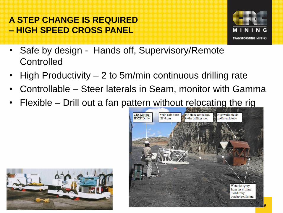
A STEP CHANGE IS REQUIRED
– HIGH SPEED CROSS PANEL
• Safe by design - Hands off, Supervisory/Remote
Controlled
• High Productivity – 2 to 5m/min continuous drilling rate
• Controllable – Steer laterals in Seam, monitor with Gamma
• Flexible – Drill out a fan pattern without relocating the rig
20
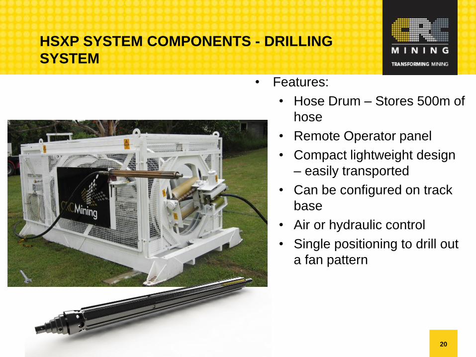
HSXP SYSTEM COMPONENTS - DRILLING
SYSTEM
• Features:
• Hose Drum – Stores 500m of
hose
• Remote Operator panel
• Compact lightweight design
– easily transported
• Can be configured on track
base
• Air or hydraulic control
• Single positioning to drill out
a fan pattern

21
HIGH PRESSURE PUMP
• Features:
• Configured for underground use
• Electric driven high pressure water pump delivers 250lpm @
800 Bar
• Can be positioned once, remote from multiple drilling
locations
• Separate Header tank & tool trailer

22
SPIN TEST ON RIG

23
COIL TUBE DRILLING NEW HORIZONS FOR AN ESTABLISHED TECHNOLOGY

24
WHAT IS COIL TUBE TECHNOLOGY??
First rolled out in WWII;
Operation PLUTO (Pipe Laying
Under The Ocean) rolled 100km of
75mm steel tube from England to
France to support the D Day
invasion.
1,000,000 gallons of fuel a day
was delivered through 6 pipes.
Pumping stations disguised as Ice
Cream Factory and Houses.
Concept, R&D, Prototyping, Full
scale in 2 Years !!!!!

25
WHAT IS COIL TUBE TECHNOLOGY?
First drilling application patent
followed a few years later;
Major components already
identified;
Arch Rollers
Injector
Reel & Drive

26
WHAT IS COIL TUBE TECHNOLOGY??
Modern Rigs have not changed a
great deal;
Major components still there;
Arch Rollers
Injector
Reel & Drive

27
WHAT’S AN UNDERGROUND CT RIG LOOK LIKE??
They come in all sizes;

28
HOW TO STEER A COIL BHA? (2009)
2009:
•All use bent subs with
orientors – Tier 1
technology
•Subs not available for
purchase – can be rented
for $60k per week – Tier
one pricing

29
WHAT (WAS) IT GOING TO LOOK LIKE?
Real & Drive
Arch Rollers
Injector

30
FATIGUE TRIALS OF COMPACT REEL

31
TUBE STRAIGHTENING DEMONSTRATION

32
2013:
•Rotary Steerable is here
– Tier one technology
•Orienter subs – Tier 2
technology – can
purchase for $8k.
HOW TO STEER A COIL BHA? (2013)

33
WHAT DOES THIS MEAN?
Orienter sub in the BHA means…
A conventional rig concept can be used
• Larger diameter coil
• Longer reach
• Double tubing fatigue life
• ~200cycles

34
BOREHOLE GAS FLOW EVENT DETECTION UNDERSTANDING GAS DRAINAGE
PRODUCTION

35
BACKGROUND
The monitoring of gas flow in gas drainage holes at coal mines is
usually carried out by measuring the flow at the borehole collar,
or seldom monitored at all.
The current method does not provide any information on where
the gas flow originated and how effective the gas drainage was
throughout a region.
This can result in extra costs of $100Ks to ameliorate the
problem, and $Millions in losses per day due to production down
time.
36
AIM
CRC Mining is developing a system for gas monitoring inside
boreholes that will detect gas flow & other events to determine
the distribution of gas release from the coal seam along the
entire length of the borehole.
The system works on the principle of Distributed Temperature
Measurement.
Gas flow events inside the borehole produce temperature
footprints that can be utilised to identify the locations where gas
flow originates.

37
EQUIPMENT – DTS
Low Power
Monitoring System
High Precision DTS
Computer

38
RESULTS – CARBOROUGH DOWNS

39
RESULTS – BULGO SANDSTONE
40
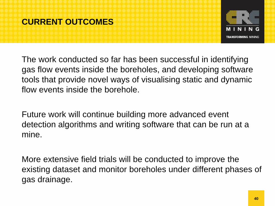
CURRENT OUTCOMES
The work conducted so far has been successful in identifying
gas flow events inside the boreholes, and developing software
tools that provide novel ways of visualising static and dynamic
flow events inside the borehole.
Future work will continue building more advanced event
detection algorithms and writing software that can be run at a
mine.
More extensive field trials will be conducted to improve the
existing dataset and monitor boreholes under different phases of
gas drainage.

41
CRCMINING TRANSFORMING MINING
![TRANSFORMING INEQUALITIES, TRANSFORMING …...GENDER EQUALITY & INCLUSION STRATEGY [2017-21] Save the Children in Bangladesh TRANSFORMING INEQUALITIES, TRANSFORMING LIVES Gender Equality](https://static.fdocuments.in/doc/165x107/5f3a3c5f5961975095630410/transforming-inequalities-transforming-gender-equality-inclusion-strategy.jpg)


![TRANSFORMING RAILWAYS TRANSFORMING INDIAindianrailways.gov.in/railwayboard/uploads/directorate/prd/... · TRANSFORMING RAILWAYS TRANSFORMING INDIA;k=kh dh xfjek] ... We have set before](https://static.fdocuments.in/doc/165x107/5b0bf5897f8b9a952f8b4e30/transforming-railways-transforming-railways-transforming-indiakkh-dh-xfjek-.jpg)