Crawler Mechanism with Circular Section to Realize a...
6
Abstract— In this paper, a novel crawler mechanism for a sideling motion is presented. The crawler mechanism has a circular section and has active rolling axes at the center of the circles. Conventional crawler mechanism can convey heavy weigh, however they can not move to side. And previous crawler unit sinks into the soft ground when it whole body is inclined during moving. The proposed design solves this drawback by means of a circular section. An actual prototype model has been developed to illustrate the concept and to perform preliminary motion experiments, through which the basic performance of the Crawler Vehicle with this proposed Omni-Crawler mechanism was confirmed. An prototype has been developed to illustrate the concept. Motion experiments, with a test vehicle are also presented. Keywords: Crawler, Sideling Motion, Circular Section, Mechanical Design, Pipe Inspection I. INTRODUCTION revious crawler can not move to a side way. Therefore it is difficult for previous crawler to avoid the obstacle and immediately as shown in Fig. 1(a). In addition, when previous crawler move on the soft ground, the edge of the crawler unit is apt to sink as shown in Fig. 1(b). In this paper, the crawler mechanism to realize a sideling motion and . Application for Pipe inspection robot. B. Weak point of conventional crawler which realize the sideways mobility In order to realize holonomic omni-directional motion, there exist some many commercial wheels with based on small passive rotational wheels. However, these mechanisms do not have a high level of ability for step climbing or gap traversal (for example the chasm of the door of an elevator) in environments, such as houses, offices and hospitals. This limitation stems form the fact that the diameter of the passive wheels is much smaller than the diameter of the whole wheel mechanism. This is particularly apparent when the mobile Massachusetts Institute of Technology 1 ,Tokyo Institute of Technology 2 , AIST 3 , Harvard University 4 Hyperion Power Technologies 5 ,[email protected], Room: 3-473m, 77 Massachusetts Ave., Cambridge, MA 02139 USA [ Front View ] [ Oblique View ] (a)Difficulty to Adjust the Position, Going Into Narrow Space (Top View ) (b)Sinking from the Edge in Soft Ground Narrow Space Body of theVehicle Crawler Unit Soft Ground Obstacle Soft Ground Obstacle Obstacle Crawler Unit Body of theVehicle 1 2 3 4 2 4 5 A B C C C Fig. 1: Problems of Conventional Crawler Mechanism II. BASIC CONCEPT OF THE CRAWLER WITH CIRCULAR SECTION The basic concept of the Crawler with circular section is shown in Fig. , The crawler has the circular section. And this crawler module has the active rotational axis. Therefore, the sideway motion can be realized by this configuration. In addition above feature, this configuration has another point as shown in Fig. 3. Crawler Unit with Circular Section Active Rolling Axes Normal Motion of the Track Body of the Vehicle Crawler Unit with Circular Section Fig. 2: Basic Concept of Omni-Crawler with Circular Section Crawler Mechanism with Circular Section to Realize a Sideling Motion Kenjiro Tadakuma 1 , Riichiro Tadakuma 2 , Keiji Nagatani 1 , Kazuya Yoshida 1 , Karl Iagnemma 3 P CONFIDENTIAL. Limited circulation. For review only. Preprint submitted to 2008 IEEE/RSJ International Conference on Intelligent Robots and Systems. Received February 23, 2008.
Transcript of Crawler Mechanism with Circular Section to Realize a...

Abstract— In this paper, a novel crawler mechanism for a sideling
motion is presented. The crawler mechanism has a circular section and has active rolling axes at the center of the circles. Conventional crawler mechanism can convey heavy weigh, however they can not move to side. And previous crawler unit sinks into the soft ground when it whole body is inclined during moving. The proposed design solves this drawback by means of a circular section. An actual prototype model has been developed to illustrate the concept and to perform preliminary motion experiments, through which the basic performance of the Crawler Vehicle with this proposed Omni-Crawler mechanism was confirmed. An prototype has been developed to illustrate the concept. Motion experiments, with a test vehicle are also presented. Keywords: Crawler, Sideling Motion, Circular Section, Mechanical Design, Pipe Inspection
I. INTRODUCTION
revious crawler can not move to a side way. Therefore it is difficult for previous crawler to avoid the obstacle and
immediately as shown in Fig. 1(a). In addition, when previous crawler move on the soft ground, the edge of the crawler unit is apt to sink as shown in Fig. 1(b). In this paper, the crawler mechanism to realize a sideling motion and .
Application for Pipe inspection robot.
B. Weak point of conventional crawler which realize the sideways mobility In order to realize holonomic omni-directional motion, there
exist some many commercial wheels with based on small passive rotational wheels. However, these mechanisms do not have a high level of ability for step climbing or gap traversal (for example the chasm of the door of an elevator) in environments, such as houses, offices and hospitals. This limitation stems form the fact that the diameter of the passive wheels is much smaller than the diameter of the whole wheel mechanism. This is particularly apparent when the mobile
Massachusetts Institute of Technology1,Tokyo Institute of Technology2, AIST3, Harvard University4 Hyperion Power Technologies5,[email protected], Room: 3-473m, 77 Massachusetts Ave., Cambridge, MA 02139 USA
[ Front View ]
[ Oblique View ]
(a)Difficulty to Adjust the Position,Going Into Narrow Space ( Top View )
(b)Sinking from the Edge in Soft Ground
Narrow Space
Body of theVehicle
Crawler Unit
Soft Ground
Obstacle
Soft Ground
Obstacle
Obstacle
Crawler Unit
Bodyof theVehicle
1
2
3
4
2 4
5
A
B CC C
Fig. 1: Problems of Conventional Crawler Mechanism
II. BASIC CONCEPT OF THE CRAWLER WITH CIRCULAR SECTION
The basic concept of the Crawler with circular section is shown in Fig. , The crawler has the circular section. And this crawler
module has the active rotational axis. Therefore, the sideway motion can be realized by this configuration. In addition above feature, this configuration has another
point as shown in Fig. 3.
Crawler Unitwith Circular Section
Active Rolling AxesNormal Motion of the Track
Body of the VehicleCrawler Unitwith Circular Section
Fig. 2: Basic Concept of Omni-Crawler with Circular Section
Crawler Mechanism with Circular Section to Realize a Sideling Motion
Kenjiro Tadakuma1, Riichiro Tadakuma2, Keiji Nagatani1, Kazuya Yoshida1, Karl Iagnemma3
P
CONFIDENTIAL. Limited circulation. For review only.
Preprint submitted to 2008 IEEE/RSJ International Conference onIntelligent Robots and Systems. Received February 23, 2008.

Basic Motion Direction of the Vehicle
r R
w
Large
Small
Rad
ius
of C
ircul
ar S
ectio
n of
Fie
lds
(a) Inner Pipe (b) Outer Pipe
Body of the Vehicle
Crawler Unitwith Circular Section
Fig. 3 Auto-Adjustable Function to the Curved Field like Pipe without any special degrees of freedom
When previous crawlers move inside of pipes or outer surface of pipes, the edge of the crawler belt are contacted at points. On the other hand, when the crawler with circle section moves inside or outer surface of pipes, the crawler unit practically contacts the surface with some areas, because of the deformation of the surface of the circular crawler belt, the touching area of the crawler unit should be changed with some area not the line.
In addition, as mentioned in the introduction as the problem of the previous vehicle, the depth of sink of the crawler unit can be reduced.
To move pipes to the vertical direction, with more than 3 units, the vehicle can move toward to the top inside vertical pipes.
If the vehicle has the joint mechanism between the former crawler module and rear one, the vehicle can climb much high steps like the Packbots[] doing. robots mounting these mechanisms move in the direction
perpendicular to the passive wheel axis as shown in Fig. 2. The step that the mobile robots can overcome is significantly low if compared to the size of the whole wheel because of the small diameter of the passive wheels. In this paper, we propose a new wheel mechanism with high
step climbing capability for omnidirectional mobile robots, and show the mechanical design of that wheel in detail.
III. MECHANISM OF THE CRAWLER WITH CIRCULAR SECTION
In this section basic configuration of the crawler mechanism with circular section is described. At first, the mechanism of the Omni-Ball[] authors developed before, being based on the crawler mechanism is explained.
A. Basic Configuration of “Omni-Ball” A driving mechanism that facilitates motion in an
omnidirectional way is feasible by using a spherical ball[9]. However, this mechanism has many mechanical parts such as rollers and guides, etc. One of the key developments presented in this paper is a new mechanism for AGV to realize that omni-directional motion with symmetric property. The basic section structure of “Omni-Ball” is shown in
Fig.4[10] and a 3D-concept model is shown in Fig.5. In Fig. 5 two hemispheres rotate passively, and in the center of the Omni-Ball lays the active rotational axis. In order to rotation, both the passive hemispheres. Note that each passive rotational axis is independent, so that each rotation of hemispheric wheel is also independent. When the active axis rotates, the Omni-Ball produces a
propelling force in a perpendicular direction to the active rotational axis, as shown in Fig.4. On the other hand, this wheel does not produce a propelling force in the horizontal direction in Fig.4(right one), so that this mechanism can similarly move in an arbitrary direction by combining through the combination of at least three propelling forces. As a more practical model, a motor for a wheel type is being designed. By placing the motor inside the wheel itself, the whole structure of the Omni-Ball becomes more compact.
Active Rotational Axis
Passive Rotational Axis
Passive Rotational Axis
Bearing
Hemisphere Wheel
Geared Motor(Rotary Actuator)
Propelling Force
Passive Movement Fig.4: Basic Structure of the “Omni-Ball”
B. Basic Configuration of “Omni-Crawler”
The comparison between the principle of the Omni-Ball and that of the Omni-Crawler is shown in Fig. .
CONFIDENTIAL. Limited circulation. For review only.
Preprint submitted to 2008 IEEE/RSJ International Conference onIntelligent Robots and Systems. Received February 23, 2008.

As stated in the previous section, the hemispherical wheel of the Omni-Ball is rotated passively in Fig. , on the other hand, the Omni-Crawler can produce propelling force not only the side-way but also forward-back way. If the rotary actuator mount on the hemispherical wheel of the Omni-Ball, the velocity in the forward-back way must be changed depends on the angle of the axis of the hemispherical wheel to the ground, because the relative radius of the should be change based on the inclining angle of the wheel mechanism. On the other hand, as shown in Fig. 5(b), the Omni-Crawler the crawler mechanism to realize a sideling motion, the velocity to the crawler to forward direction does not change based on the inclining angle of the driving unit as shown in Fig. 5[b-1] and [b-2].
θ
ωr
o P
Passive
Active
[ b-2 ] Omni-Crawler
[ a-2 ] Omni-Ball(Bottow View)
(Bottow View)
ActiveRotation
ActiveRotation
Trac
tion
Dire
ctio
n
o1 P1
o2 P2
Active Rotation
Active Linear Motion
Traction DirectionTraction Direction
Contact Line
ContactPoint
Pas
sive
Mov
emen
t
LinearDriving Area
ωrωr
P
[ a-1 ] Omni-Ball(Front View)
oθ
r RP
[ b-1 ] Omni-Crawler(Front View)
oθ
r R
Fig.5: Basic Principle of the “Omni-Crawler”
C. Actual Prototype Model of “Omni-Crawler” (c-1) Inner Mechanism of the Crawler The inner mechanism of the crawler is shown in Fig. 6. The geared motor rotates the inner shaft and bevel gear set change its rotational direction to the vertical direction to the shaft of the motor and sprocket is rotated at the end. The end of the front and rear of the inner mechanism unit, there are the shaft for the sideling motion of the crawler. By rotating these shaft in rolling axis actively, the sideway motion can be realized. Tensioner for the belt is mounted at the reaer part.
AAA Batteryfor size comparison
Guide of the Belt
Sprocket
Geared Motor
Coupling
Rolling Axis for Sideling Motion
Tensioner
Bevel Gear Set
ScrewTensioner
Fig.6: Mechanism inside the Crawler Unit
(c-2) Crawler Belt with Circular Lug In order to realize smooth sideling motion, the shape of the section of the crawler should be circle. The lug of the crawler is shown in Fig. The Surface of the Lug module, the rubber is set to the lug supporter. The material of the lug supporter is SUS304; metal. The overview of the belt of the crawler is shown in Fig.8.
AAA Batteryfor size comparison
Lug Supporter(Bent SUS304)
Surface Rubber of the Circular Lug
Screw Hole
Fig.7: Lug of the Crawler Belt
Fig.8: Belt of the Crawler (top one is reverse side of
the crawler)
CONFIDENTIAL. Limited circulation. For review only.
Preprint submitted to 2008 IEEE/RSJ International Conference onIntelligent Robots and Systems. Received February 23, 2008.

(a) Oblique View the Crawler Unit
Lug of the Crawler
(b) Front View
(c) Access to the tensioner
AAA Batteryfor size comparison
L- hex wrench
ScrewTensioner
Fig.9: Actual Prototype Model of “Omni-Crawler”
Unit Table.1 Specification of One “Omni-Crawler”
IV. Configuration of the Crawler Vehicle The configuration of the vehicle is shown in Fig. 10 and specification of the vehicle is shown in tab.2. There is the motor to rotate both axes of rolling shaft from the right and left crawler units for realizing sideling motion. The battery and electronic circuit boards are mounted on top of the body.
Fig.10: Whole View of the Crawler Vehicle
Table.2 Specification of the Vehicle
. EXPERIMENTS OF THE CRAWLER VEHICLE In this section, we describe a set of experiments conducted to confirm the performance of an actual prototype model of this crawler vehicle with omni-crawler A. Omnidirectional Motion
As one of the basic performances of this robot, the omnidirectional motion should be confirmed. One example of such motions is shown in Fig.11. It was observed that this prototype model has the ability to move in an arbitrary direction smoothly. Please see the movie attached on this paper.
CONFIDENTIAL. Limited circulation. For review only.
Preprint submitted to 2008 IEEE/RSJ International Conference onIntelligent Robots and Systems. Received February 23, 2008.
1
2
3
4
5
6
7
8
Fig.11: Omnidirectional Motion on Floor
0
20
40
60
80
100
120
140
160
0 20 40 60 80
Experimental
Omni-BallOmni-CrawlerV
eloc
ity (m
m/s
)
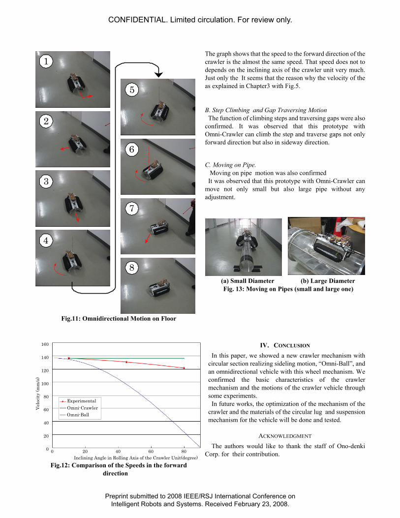
Inclining Angle in Rolling Axis of the Crawler Unit(degree) Fig.12: Comparison of the Speeds in the forward
direction
The graph shows that the speed to the forward direction of the crawler is the almost the same speed. That speed does not to depends on the inclining axis of the crawler unit very much. Just only the It seems that the reason why the velocity of the as explained in Chapter3 with Fig.5. B. Step Climbing and Gap Traversing Motion The function of climbing steps and traversing gaps were also
confirmed. It was observed that this prototype with Omni-Crawler can climb the step and traverse gaps not only forward direction but also in sideway direction.
C. Moving on Pipe. Moving on pipe motion was also confirmed It was observed that this prototype with Omni-Crawler can
move not only small but also large pipe without any adjustment.
(a) Small Diameter (b) Large Diameter Fig. 13: Moving on Pipes (small and large one)
IV. CONCLUSION In this paper, we showed a new crawler mechanism with
circular section realizing sideling motion, “Omni-Ball”, and an omnidirectional vehicle with this wheel mechanism. We confirmed the basic characteristics of the crawler mechanism and the motions of the crawler vehicle through some experiments.
In future works, the optimization of the mechanism of the crawler and the materials of the circular lug and suspension mechanism for the vehicle will be done and tested.
ACKNOWLEDGMENT The authors would like to thank the staff of Ono-denki
Corp. for their contribution.
CONFIDENTIAL. Limited circulation. For review only.
Preprint submitted to 2008 IEEE/RSJ International Conference onIntelligent Robots and Systems. Received February 23, 2008.

REFERENCES [1] A control system for an omnidirectional mobile robot, Paromtchik,
I.E.; Asama, H.; Fujii, T.; Endo, L.;Control Applications, 1999. Proceedings of the 1999 IEEE International Conference on Volume 2, 22-27 Aug. 1999 Page(s):1123 - 1128 vol. 2
[2] Atsushi Yamashita, Hajime Asama, Hayato Kaetsu, Isao Endo and Tamio Arai: “Development ofOmniDirectional and Step-Climbing Mobile Robot”,Proceedings of the 3rd International Conference onField and ServiceRobotics (FSR2001), pp.327-332, Espoo(Finland), June 2001.
[3] http://www.omniwheel.com/ (at the present day, April 8th) [4] Low vibration omni-directional wheel, Patent number: 6547340, Filing
date: Dec 6, 2001, Issue date: Apr 15, 2003, Inventor: Donald Barnett Harris, Assignee: Airtrax Corporation, Primary Examiner: S. Joseph Morano, Secondary Examiner: Long Bao Nguyen, Attorney: Foley & Lardner
[5] Omni-directional munitions handling vehicle; Patent number: 6668950, Filing date: May 9, 2002, Issue date: Dec 30, 2003, Inventor: Andrew D. Park, Primary Examiner: Kevin Hurley, Attorney: Schwartz Law Firm, P.C.
[6] http://www.kanto-aw.co.jp/en/ [7] "Omnidirectional Vehicle", Applicant: Kanto Auto Works , Inventor:
Hideki Toda, Japanese Patent application for a patent:2003-203645, date of application:30th, July, 2003, publication number: Patent disclosure2005-47312, date of publication of unexamined patent application: 24th, Feb, 2005,
[8] "Omnidirectional Wheel and Mobile Platform", Applicant: Shinichi Fuji, Inventor: Shinichi Fuji, Japanese Patent application for a patent:2004-367219, date of application:20th, Dec, 2004, publication number: Patent disclosure2006-168659, date of publication of unexamined patent application: 29th, Jun, 2006
[9] “Design and control of ball wheel omnidirectional vehicles”, West, M.; Asada, H.; Proceedings., 1995 IEEE International Conference on Robotics and Automation, Volume 2, 21-27 May 1995 Page(s):1931 - 1938 vol.2 Digital Object Identifier 10.1109/ROBOT.1995.525547
[10] Tadakuma, K.; "Tetrahedral Mobile Robot with Novel Ball Shape Wheel", The First IEEE/RAS-EMBS International Conference on Biomedi-cal Robotics and Biomechatronics, 2006. BioRob 2006. February 20-22, 2006 Page(s):946 – 952
[11] http://www.tosadenshi.co.jp/tsuhan/omni/uretanomni.html
CONFIDENTIAL. Limited circulation. For review only.
Preprint submitted to 2008 IEEE/RSJ International Conference onIntelligent Robots and Systems. Received February 23, 2008.