Crash Propagation in Automotive Batteries: Simulations and ... · given set of test conditions. ......
19
NREL is a national laboratory of the U.S. Department of Energy, Office of Energy Efficiency and Renewable Energy, operated by the Alliance for Sustainable Energy, LLC. Crash Propagation in Automotive Batteries: Simulations and Validation Principal Investigator: Shriram Santhanagopalan Team: Chao Zhang, Michael A. Sprague, Ahmad Pesaran National Renewable Energy Laboratory Jim Marcicki, Phil Rairigh, Xiao Guang Yang, Alex Bartlett Ford Motor Company June 9, 2015 Project ID: ES236 This presentation does not contain any proprietary, confidential, or otherwise restricted information.
Transcript of Crash Propagation in Automotive Batteries: Simulations and ... · given set of test conditions. ......

NREL is a national laboratory of the U.S. Department of Energy, Office of Energy Efficiency and Renewable Energy, operated by the Alliance for Sustainable Energy, LLC.
Crash Propagation in Automotive Batteries: Simulations and Validation
Principal Investigator: Shriram SanthanagopalanTeam: Chao Zhang, Michael A. Sprague, Ahmad PesaranNational Renewable Energy LaboratoryJim Marcicki, Phil Rairigh, Xiao Guang Yang, Alex BartlettFord Motor Company
June 9, 2015 Project ID: ES236
This presentation does not contain any proprietary, confidential, or otherwise restricted information.

2
Overview
• Project start date: 01/2014• Project end date: 01/2016• Percent complete: 60%
• Battery electric vehicle battery safety following a mechanical impact is poorly understood.
• Lack of experimental data to understand battery electrical and thermal response during crash-induced crush.
• Existing test procedures have control values (e.g., crash velocity or stop condition) set to arbitrary values for a given set of test conditions.
• Total project funding:o DOE share: 100%o Contractor share: 0%
• Funding received in FY14: 475k• Anticipated Funding for FY15: 500k
Timeline
Budget
Barriers
• Ford Motor Company• Sandia National Laboratories (SNL)• USCAR Crash Safety Work Group
Partners
USCAR = U.S. Council for Automotive Research

3
• Developing abuse-tolerant plug-in electric vehicle (PEV) batteries is identified on the agenda proposed in VTO’s 2013 Annual Progress Report for Energy Storage.
• This project was started to understand battery safety from the systems standpoint: o Most experimental and modeling investigations focus on
understanding origin of failure at the sub-cell level.o Very limited sub-set of test data translates to actionable
information towards improving safety of battery modules.o The goal of this effort is to start with a lumped representation of
the cell level performance and quickly move on to multi-cell response to mechanical deformation similar to a crash event.
• The end goal is to better inform and interpret mechanical testing of battery safety and design safer packs.
Relevance
4
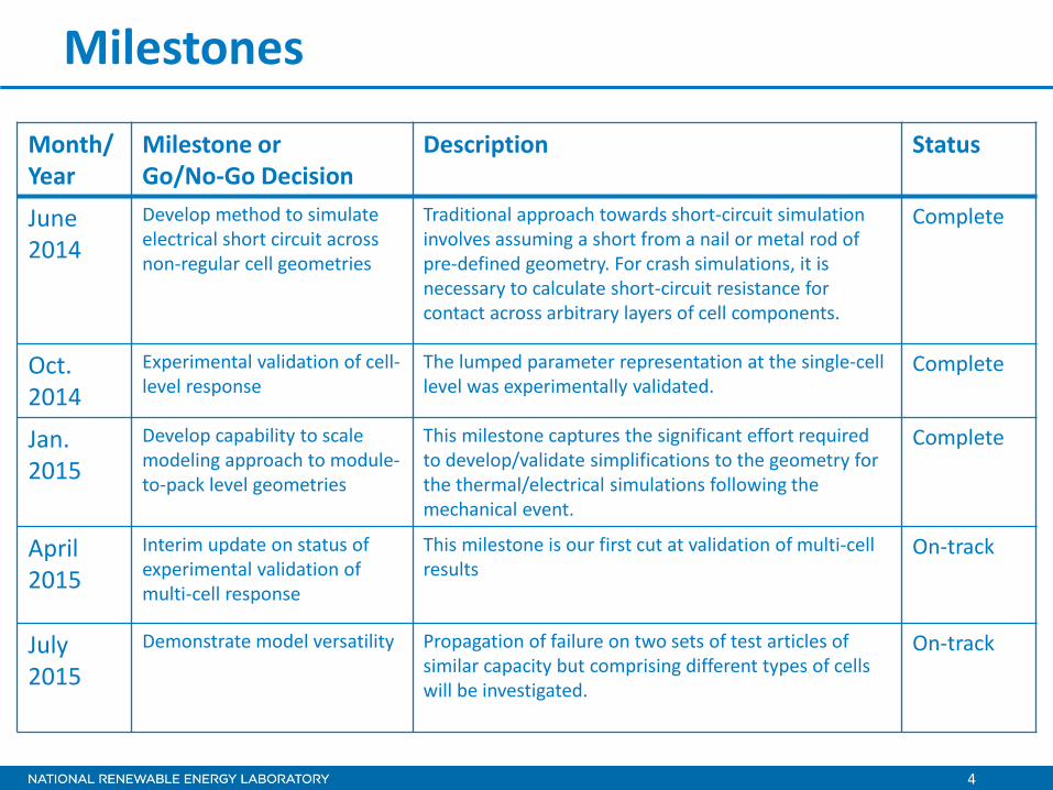
Milestones
Month/ Year
Milestone or Go/No-Go Decision
Description Status
June 2014
Develop method to simulate electrical short circuit across non-regular cell geometries
Traditional approach towards short-circuit simulation involves assuming a short from a nail or metal rod of pre-defined geometry. For crash simulations, it is necessary to calculate short-circuit resistance for contact across arbitrary layers of cell components.
Complete
Oct. 2014
Experimental validation of cell-level response
The lumped parameter representation at the single-cell level was experimentally validated.
Complete
Jan. 2015
Develop capability to scale modeling approach to module-to-pack level geometries
This milestone captures the significant effort required to develop/validate simplifications to the geometry for the thermal/electrical simulations following the mechanical event.
Complete
April 2015
Interim update on status of experimental validation of multi-cell response
This milestone is our first cut at validation of multi-cell results
On-track
July2015
Demonstrate model versatility Propagation of failure on two sets of test articles of similar capacity but comprising different types of cells will be investigated.
On-track

5
Modeling Approach
Scope Cell-Level Cell-Strings Module-LevelInput • Electrical, thermal and
mechanical data or modelson cell components• Cell assembly information (wound, stacked, etc.)
• Mechanical models and/or data for individual cells• Heat generation data or models for the cell under short circuit
• Mechanical models and/or test data for individual cells• Heat generation model or datafor the cell under short circuit• Properties of packaging material, module configuration
Output • Lumped mechanical models representative of the cell-level response• Electrical/thermal simulations on the deformed geometry
• Origin and propagation of electrical/thermal phenomena, when multiple short-circuit events occur across the string during crush
• Origin and propagation of electrical/thermal phenomena under crush• Identification of weak-spots on the module to monitor/take preventive measures
Utilizing Cell-Level Information to Predict Crush Performance of Modules
Cell String Module
Propagation phenomena under crush
Interaction of mechanical/electrical/thermal effects
6
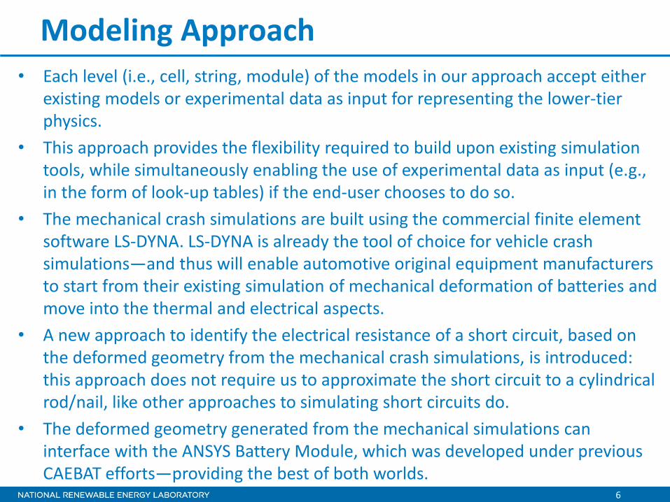
Modeling Approach • Each level (i.e., cell, string, module) of the models in our approach accept either
existing models or experimental data as input for representing the lower-tier physics.
• This approach provides the flexibility required to build upon existing simulation tools, while simultaneously enabling the use of experimental data as input (e.g., in the form of look-up tables) if the end-user chooses to do so.
• The mechanical crash simulations are built using the commercial finite element software LS-DYNA. LS-DYNA is already the tool of choice for vehicle crash simulations—and thus will enable automotive original equipment manufacturers to start from their existing simulation of mechanical deformation of batteries and move into the thermal and electrical aspects.
• A new approach to identify the electrical resistance of a short circuit, based on the deformed geometry from the mechanical crash simulations, is introduced: this approach does not require us to approximate the short circuit to a cylindrical rod/nail, like other approaches to simulating short circuits do.
• The deformed geometry generated from the mechanical simulations can interface with the ANSYS Battery Module, which was developed under previous CAEBAT efforts—providing the best of both worlds.

7
Technical Accomplishments and Progress

8
Mechanical Model for Impact Simulations• The response of individual cells subjected to mechanical
crush was simulated using LS-DYNA.• The approach established was to:
o import computer-aided design (CAD) geometries for cells into LS-DYNA
o generate a mesh to perform calculations in a reasonable time frame
o export the results back to computational fluid dynamics software (e.g., ANSYS).
• The use of shell elements to track the deformed geometry greatly reduces the computational time.
• A representative sandwich model was used to simulate cell performance.
• The regeneration of solid parts from the deformed geometry is currently done on a case-by-case basis.
• Crash simulations were performed on different cell formats, under various impact conditions to demonstrate the versatility of the approach.
• The deformed geometries are used in short-resistance calculations shown later.
An electrode pair subjected to crush
Prismatic cell crashing on to a wall
Pouch cell – deformed geometry
Model Versatility: multiple cell types, various load conditions
Crush bar

9
Estimating Short-Circuit ResistanceRegular Short (Previously Reported Approach):
Irregular Short (Current Approach):
Use ionic and electronic resistivity of the deformed layers change as a function of thickness
Before fracture
After fracture
We calculate the short resistance by solving Maxwell’s equations using deformed geometryfrom LS-DYNA and properties of individual layers
Cathode
Separator
Anode
CC
Assumed short-circuit resistance
Reff
Nail penetrating a cell
Deformed geometry obtained using CAD geometry of cells subjected to crush in LS-DYNA
Kalupson et al., ECS Spring Meeting, Orlando FL, April 2014.
Gi-Heon Kim, 6th Lithium Mobile Power Conference, Boston MA, 2010.

10
Test Facility and Set Up Cell Fixtures
Experimental efforts by Ford to validate impact simulation results:• The cells were of 15-Ah pouch format, with an LMO+NMC cathode.• Custom fixtures were built to minimize cell movement during the X- and the Z-plane impact.• The variables controlled to vary the impact of the load include the initial height (1m, 2m) and
the weight of the load (32 kg, 14 kg).
Z-plane X-plane
Experimental Validation of Single Cell Results
Picture Credits: Jim Marcicki, Ford Motor Company
11
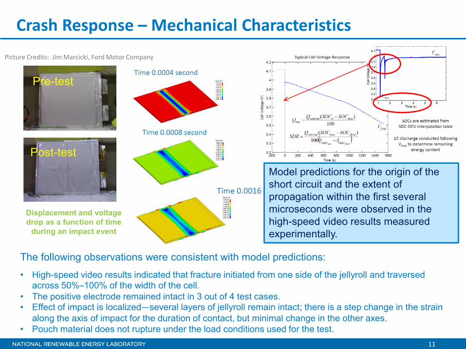
Crash Response – Mechanical Characteristics
Pre-test
Post-test
The following observations were consistent with model predictions:
• High-speed video results indicated that fracture initiated from one side of the jellyroll and traversed across 50%–100% of the width of the cell.
• The positive electrode remained intact in 3 out of 4 test cases.• Effect of impact is localized—several layers of jellyroll remain intact; there is a step change in the strain
along the axis of impact for the duration of contact, but minimal change in the other axes.• Pouch material does not rupture under the load conditions used for the test.
Model predictions for the origin of the short circuit and the extent of propagation within the first several microseconds were observed in the high-speed video results measured experimentally.
Displacement and voltage drop as a function of time
during an impact event
Picture Credits: Jim Marcicki, Ford Motor Company

12
Crash Response – Electrical Characteristics
Model predictions (solid line) vs. experimental data from high-speed imagery (dots): Consistent with the model predictions, the initial voltage drop varies directly as a function of contact time with the load.
• Initial voltage drop varies from 70mV – 0.9V.• All cells exhibit a sustained internal short
circuit, but EUCAR 2 response.
Voltage Drop
• Four repeats under identical test conditions showed different voltage drop from the initial 4.15 V (80% state of charge [SOC]).
• High-speed video results indicated different contact times between the impact load and the cells to be the source of variability.
• Different contact times were simulated to compare with the experimental results: resistance of short varies with the duration of contact.
• This metric is predictive and can be used as an indicator of the remaining energy in the battery at any given time after the crash. This result has significant implications towards safety assessment of battery packs after crash.
13
Crash Response – Thermal Characteristics
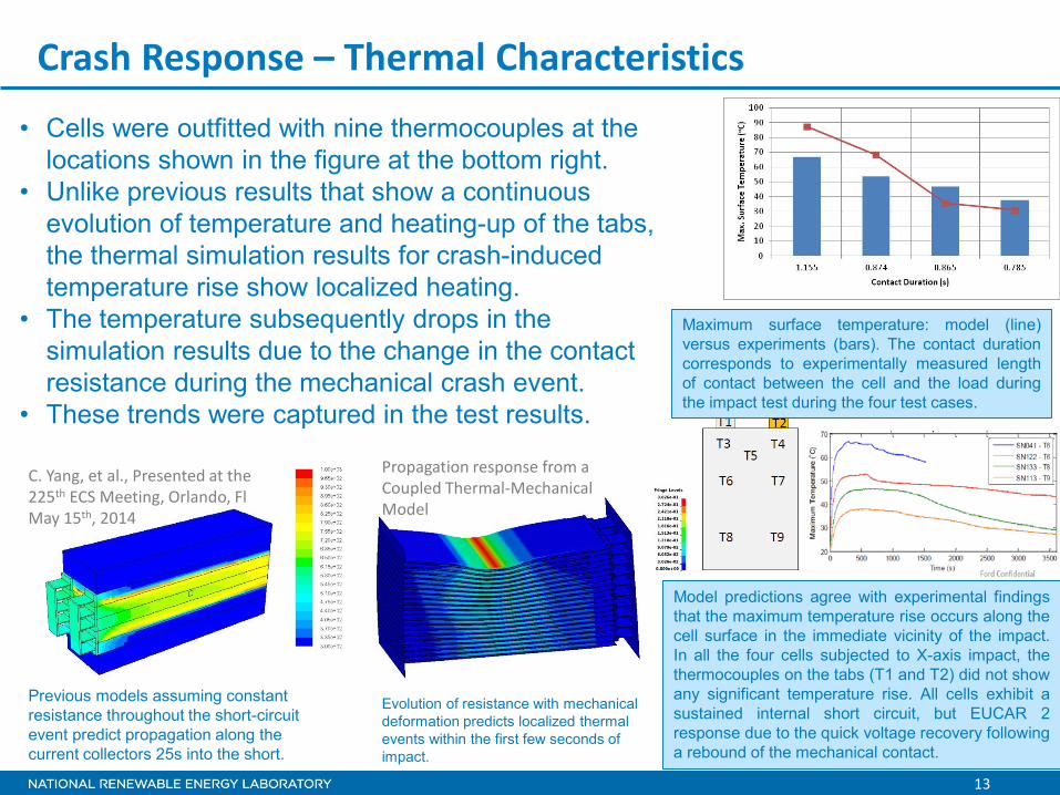
• Cells were outfitted with nine thermocouples at the locations shown in the figure at the bottom right.
• Unlike previous results that show a continuous evolution of temperature and heating-up of the tabs, the thermal simulation results for crash-induced temperature rise show localized heating.
• The temperature subsequently drops in the simulation results due to the change in the contact resistance during the mechanical crash event.
• These trends were captured in the test results.
Previous models assuming constant resistance throughout the short-circuit event predict propagation along the current collectors 25s into the short.
C. Yang, et al., Presented at the 225th ECS Meeting, Orlando, FlMay 15th, 2014
Evolution of resistance with mechanical deformation predicts localized thermal events within the first few seconds of impact.
Model predictions agree with experimental findingsthat the maximum temperature rise occurs along thecell surface in the immediate vicinity of the impact.In all the four cells subjected to X-axis impact, thethermocouples on the tabs (T1 and T2) did not showany significant temperature rise. All cells exhibit asustained internal short circuit, but EUCAR 2response due to the quick voltage recovery followinga rebound of the mechanical contact.
Propagation response from a Coupled Thermal-Mechanical Model
Maximum surface temperature: model (line)versus experiments (bars). The contact durationcorresponds to experimentally measured lengthof contact between the cell and the load duringthe impact test during the four test cases.

14
Multi-Cell Crush Simulations – Initial Results
• Initial results for multi-cell simulations are available.• One set of case studies with the same kind of cells packaged between cooling plates of
different configurations is shown above:o The temperature rise for impact along the x-plane is drastically different from that
along the z-plane.o The design of the cooling plates (number of parallel channels versus ΔT between the
entrance and exit, etc.) does determine the tendency of failure to propagate.
Damage Intensity
Deformation of front plate
Maximum deflection is 1.723 mm
Mechanical Response of a 20-Cell Module comprising of the same 15 Ah LMO+NMC chemistry cells used in our single-cell case studies: experimental validation is underway
15
This effort was started in FY14 and was not reviewed in the year before.
Response to Previous Year Reviewers’ Comments
16
Collaboration and Coordination with Other Institutions
Ford Motor Company:• Ford is a sub-tier partner on this project.• Ford engineers iterated with NREL in developing the validation tests presented here.• Ford also provided the requisite test articles and supervised the testing at a third party
test-site.Crash Safety Work Group:• The Crash Safety Work Group (CSWG) at USCAR provided feedback on the different
simulations performed and identified problems of relevance to the industry.• The CSWG also shared experimental test data from their in-house efforts on
understanding mechanical crush of pouch cells under different test conditions.Sandia National Laboratories:• Chris Orendorff from SNL was instrumental in bringing together SNL’s in-house work
with the CSWG and the modeling aspects of the current project.• SNL shared laboratory data on some multi-cell testing that will be part of our case-
studies in FY15.

17
Remaining Challenges and BarriersThe key challenges for FY15 are two-fold:• The first challenge is to obtain test results and compare them against
model predictions and data from multi-cell simulations. These results are particularly challenging because we do not have as good control over the experimental setup as with the single-cell measurements. For instance, the evolution of temperature with time depends on whether the cells remain in mechanical contact after the crush—and it can be challenging to address such issues during a z-axis crush of the module.
• The second challenge for next year’s work is to develop a seamless interface with existing CAEBAT tools. Our software of choice addresses in part, the challenges associated with extending the ANSYS tools to incorporate the mechanical deformation; but with larger geometries in the works, it is difficult to ensure a good quality for the mesh and adequate resolution to characterize propagation of failure.

18
Proposed Future Work• The technical area of simulating failure initiated by mechanical load is fairly new to battery
materials. Until initiation of the current project, almost all previous efforts treated batteries strictly as structural entities (i.e., essentially as a brick) without accounting for the energy content and the resultant active response to crush.
• We will continue to improve our understanding of the complex interplay between the mechanical crush and the follow-on electro-thermal interactions.
• Future work will include:o Completion of the validation work for the multi-cell simulations towards an upcoming
milestone (July 2015)o Summarizing a test procedure to characterize the mechanical response of cells, which
can then serve as input to the material models (Oct. 2015)o Developing a set of simulation studies to analyze/compare test data from various test
methods used to evaluate safety of battery cells (e.g., nail penetration, blunt-rod test, hemispherical punch test, etc.) (Dec. 2015)
• We will initiate an approach to quantify the short-circuit resistance across large geometries involving multiple cells. We will design experiments to measure short-circuit currents across multiple points within the hardware during a crash event. The actual experiments will be conducted in out-years.
19
Summary• We have established the ability to simulate mechanical events at the single-cell level:
these models are versatile in simulating different form factors of cells—prismatic can vs. pouch, stacked vs. wound, etc.
• We have demonstrated single-cell simulations on coupling mechanical deformation with electrical and thermal events. The experimental results for the single-cell simulations across the x- and z-plane crush tests agree well with the simulations in predicting:o The correct EUCAR response levelo The numerical values for the voltage drop across different contact durationso The maximum temperature rise following each test case.
• A new scalable approach to capture the short-circuit pathway from deformed mechanical geometries and to quantify short-circuit resistance has been introduced. This methodology will be refined for other crash situations (e.g., multi-axial crush) and compared against experimental measurements in ongoing work.
• Initial results for multi-cell simulations show possibilities to investigate effect of packaging material, cooling system design, etc. Ongoing experimental studies will corroborate some of these findings in FY15 milestones.
• Future efforts will also focus on the propagation of thermal events across the packaging hardware and identify key metrics such as time for propagation, likelihood of failure propagation across different impact scenario, the damage intensity and maximum temperature within the battery.