Crankshaft
17
K5106 – Marine Engineering Practice and Legislation CRANKSHAFT Types : Four(4) different types of construction 1: Fully-built up 2: Semi-built up 3: One piece(solid) 4: Welded(modern design) 1: Fully-built up. - Webs are shrunk on to journals and crankpins. - Relatively large since shrinkfits require sufficient rigidity to withstand torque without slipping. - Used in large marine diesel engines. Advantages: 1. Repair in section easy-remove the parts separately. 2. Machining can be done before assembly- reduce time and better surface finished. 3. When slipping in way of shrinkfits, extend of damage reduced. Disadvantages: 1. Large and massive. 2. Lack of grain flow, hence fatigue strength is less. 3. External lub. oil pipes required since drilling holes through shrinkfits is discouraged. 2: Semi-built up. - Webs and crankpin manufactured as a single unit(cast and forged) - Forged journals shrunk into webs. - Most popular design for large engines. 1
-
Upload
vinod-cf-cruz- -
Category
Documents
-
view
59 -
download
5
description
crankshaft
Transcript of Crankshaft

K5106 – Marine Engineering Practice and Legislation
CRANKSHAFT
Types : Four(4) different types of construction
1: Fully-built up 2: Semi-built up3: One piece(solid) 4: Welded(modern design)
1: Fully-built up.
- Webs are shrunk on to journals and crankpins.- Relatively large since shrinkfits require sufficient rigidity to withstand torque
without slipping.- Used in large marine diesel engines.
Advantages: 1. Repair in section easy-remove the parts separately.2. Machining can be done before assembly-reduce time and better
surface finished.3. When slipping in way of shrinkfits, extend of damage reduced.
Disadvantages: 1. Large and massive.2. Lack of grain flow, hence fatigue strength is less.3. External lub. oil pipes required since drilling holes through
shrinkfits is discouraged.
2: Semi-built up.
- Webs and crankpin manufactured as a single unit(cast and forged)- Forged journals shrunk into webs.- Most popular design for large engines.
Advantages: 1. Shrinkfit used only in way of web and journal.2. Benefits of grain flow in way of web and crankpin.3. Webs smaller and thus lighter compared to fully-built type.4. Larger diameter pin/journal since one shrinkfit is
required(bearing area to withstand loading increased-better lubrication).
5. Less damage due to slipping.6. Less rigid relative to one piece type and thus can accept
slight misalignment.
3: Solid-forged or one piece(monoblock/small engines).
1

K5106 – Marine Engineering Practice and Legislation
- A suitably sized steel billet is heated and worked down under steam hammer or hydraulic forging process.
- The end is first worked to form end coupling flange and journal. Next section worked will be two crankwebs and crankpin(in a form of block). Third section will be second journal followed by second block forged at correct angle to the first. Forging continued until finished. Colour of material carefully watched during forging.
- Journals and sides of webs finish-machined.Crankpin and inside of webs then machined.
- Holes and oil passages drilled. Inside passage of oil holes may be ground smooth-to reduce stress raisers. Fillet radius at ends of pins and journals ground for same reason.
- Crankpins and journals hardened if thin shell bearings are used.- Used in medium speed(journal diameter up to 400 mm), high speed and small slow
speed engines.
Advantages: 1. Increased fatigue strength due to continuous grainflow.
2. Shaft lighter and thus more crank throws in a single shaft.3. No shrinkfits necessary.
Disadvantages: 1. More rigid and thus less tolerant to misalignment.2. Difficulty in repairs(if one section cannot be repaired by
grinding or metal-spraying, whole shaft renew).
4: Welded type.
- Latest design for large engines.- Weld in middle of bearing journals(here crankshaft stresses is lowest). A narrow
gap with low heat input, combined with submerged arc welding is most suitable.- Two way of assembly adopted.
One: welded 2 crank arms together through the pin to form a crank throw. Then weld these crank throw through the main journal.Two: Forged or cast complete crank throw and then weld them together.(crankarm-a half crank throw with a half main journal cast or forged integrally to its web).
- Fatigue strength of weld joints are superior to base material(testsconducted on full-sized specimens).If fatigue fracture already present, the growth per number of cycles issame(dynamic fracture test). Angular distortions of crankshaft very smalland stresses built up during welding and partly relieved by heating causedinsignificant changes in length.
- After welding, journal post-heated to ensure slow and even cooling. Outer surface of journal machined and welds of whole shaft stress relieved. Then shaft undergo non-destructive testing.
2

K5106 – Marine Engineering Practice and Legislation
- Ultrasonic testing on outside of journal and around the weld. Magnetic-particle inspection of weld and its surroundings.
Advantages: 1. Optimum economy in weight, space and cost due to the following :A : machining and other expensive processes reduced.B : smaller and lighter webs since no holes required as in shrunkfit method.C : less inertia leads to crankshafts with higher natural frequencies(important in slow speed engines).D : Thin arms or webs leads to longer journal bearing lengths resulting in lower specific bearing pressures.E : journal diameter can be larger(since no shrinkfits) and thus bearing pressure less.
2. Approved by major classification societies.
Crankshaft material
For fully-built up and semi-built up type – unalloyed carbon steel which has beennormalized. Also low alloyed chrome – molybdenum steel.For welded type crankshaft – normalized low carbon manganese steel or hardenedand tempered low alloy Cr/Mb steel.
Material Analysis : carbon 0.2%silicon 0.32%manganese 0.7%phosphorus 0.01%sulphur 0.015%
Some design consideration(fillet radius)
3
K5106 – Marine Engineering Practice and Legislation
1. Fillet radius, R1 0.05D12. Fillet radius, R2 0.05D2 3. Fillet radius, R3 0.05D1(diameter of crankpin).
Web edges to be well rounded off. If possible, avoid drilling holes for oil ways.
Feed oil from crosshead and down to thebottom-end bearing through oil ways drilled
4
Cutter recess
Recess fillet
* Fillet radius, R is unnecessarily large- cuttered. Recess must be done to accommodate bolts. Cutter recess gives rise to high stress concentration. Can used recessed fillet

K5106 – Marine Engineering Practice and Legislation
in connecting rod.If not, oil holes must be well rounded at lipWith high surface finish.
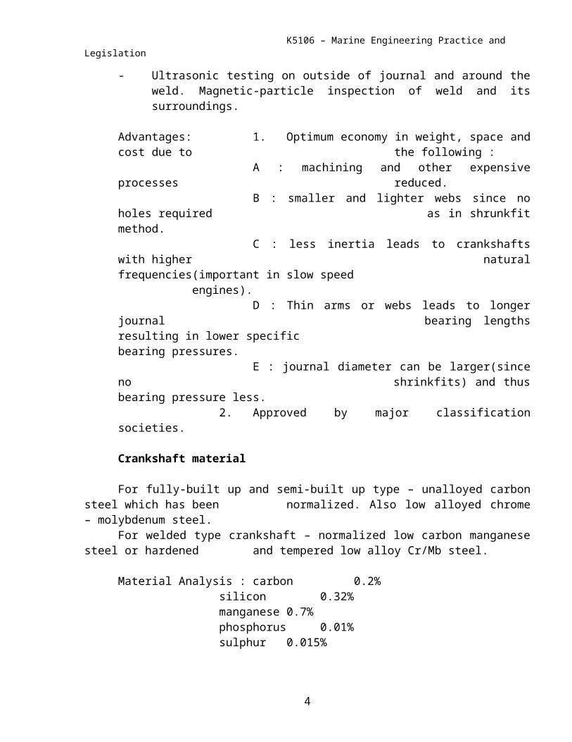
Shrinkage-fit(Instead of dowel pins)
Dowel pins disadvantages : 1. The holes for dowel pins gives sharp edges(stress concentration).
2. Crack always occur around the holes.3. Destroy the shrink fitting area(gripping part less)4. The part cannot slip – when slip dowel pin break.
Bore diameter, Db(smaller)Journal diameter Dj(larger)
Db = Dj – 1/660Dj
* shrinkage allowance is 1/570 to 1/660 ofjournal diameter.Shrinkage allowance too big – journal slack in web.Shrinkage allowance too small – materials around web
overstress and elastic limit reached(fracture)
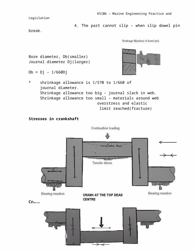
Stresses in crankshaft
Crank at the top dead centre
5

K5106 – Marine Engineering Practice and Legislation
Crank at the bottom dead centre
Note : Stresses were reversed as crank moves from TDC to BDC.Loading reversed and change in magnitude.Hence parts are subjected to fatigue considering the crankweb only.
Crank at 90o from TDC- crank pins, webs and journals lie in the plane of neutral axis.- Load on the piston 11% to 14% of load at TDC.- Load on piston and journal reaction from twisting moment caused web to act as
beam.- Bearing reaction caused shear stress or twisting in way of journal and web.
NOTE : Crank web is subjected to tensile, compressive and shear stresses. Also torsional stress, brought about by shaft reaction or load being driven are additive to those already mentioned.CRANKSHAFT FAILURE
6
Compression
TensionShear
Reaction
Support
Load
K5106 – Marine Engineering Practice and Legislation
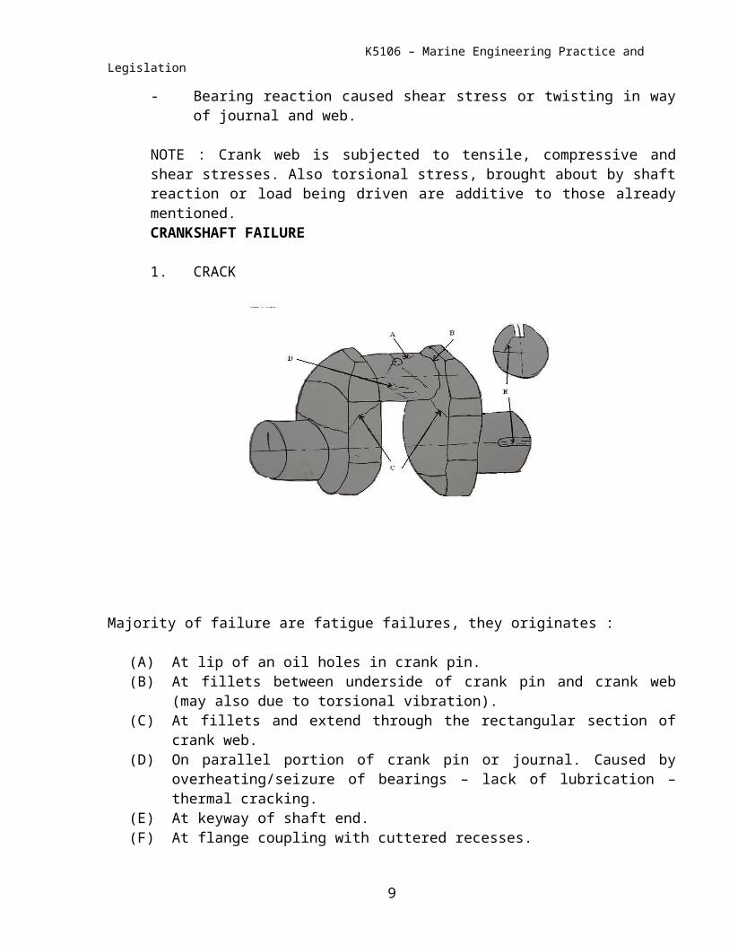
1. CRACK
Majority of failure are fatigue failures, they originates :
(A) At lip of an oil holes in crank pin.(B) At fillets between underside of crank pin and crank web (may also due to torsional
vibration).(C) At fillets and extend through the rectangular section of crank web.(D) On parallel portion of crank pin or journal. Caused by overheating/seizure of bearings –
lack of lubrication – thermal cracking.(E) At keyway of shaft end.(F) At flange coupling with cuttered recesses.(G) At crank webs, midway between pin and journal ( high stressed region).(H) At fillet between journal and web in the arc of the fillet between the position
corresponding to 10 o’clock and 2 o’clock when the piston is at TDC.
2. CRANKSHAFT TWISTING OR SLIPPING RELATIVE TO ONE ANOTHER.
This type of failure caused by :
(A) Starting engine with water or fuel trapped in space above piston( Hydraulic Lock ).
(B) Seizure of some engine components(C) Starting with turning gear in ( due to shock load ).(D) Bottom end bolt failure.
3. CRANKSHAFT MISALIGNMENT.
7

K5106 – Marine Engineering Practice and Legislation
Usually caused by :
(A) Damage main bearing/propeller shaft bearing or intermediate shaft bearing or plummer block/chocks, etc.
(B) Foundation bolts/tie bolts defective.(C) Deformation of engine foundation ( due to grounding, fire or excessive
bending moment ).(D) Weakening of structure by corrosion
4. CORROSION ATTACK ON CRANKSHAFT.
Usually caused by :
(A) Decomposition and oxidation of oil in service.(B) Contamination of L.O by sea water or fresh water.(C) Contamination of L.O by fuel oil.(D) Acidic products of combustion if they can reach the L.O in the crankcase
will cause corrosion.(E) Possibility of stray electric current entering the crankcase resulting again in
electro chemical corrosion.(F) Oil carrying air bubble in it.
Under the conditions generally prevailing in Lub. Oil system the mechanism of any corrosive attack is essentially electro chemical, involving a flow of electric current from anodic to cathodics areas. The possible electrolyte to carry this current flow are the present of NaCl due to salt water contamination and sulphur compounds from fuel oil in combination with water forming sulphurous and sulphuric acids. The anodic and cathodic areas are formed by the presence of dissimilar metals in contact with each other and localized stress forming anodic areas.
Prevention :
(A) Crankcase temperature should be maintained 500 C to 600 C to avoid condensation of water vapour.
(B) Earthing of intermediate shafting near the main engine.(C) Maintaining crankcase oil in a sufficiently alkaline or positive condition.(D) Circulation of warm oil while in port and regular turning of the engine
prevents contaminated oil from remaining static in the bearing.(E) Maintain L.O grade by filteration and centrifugal purification.(F) Additives in L.O to avoid decomposition and oxidation.
Effects of corrosion :
8
K5106 – Marine Engineering Practice and Legislation
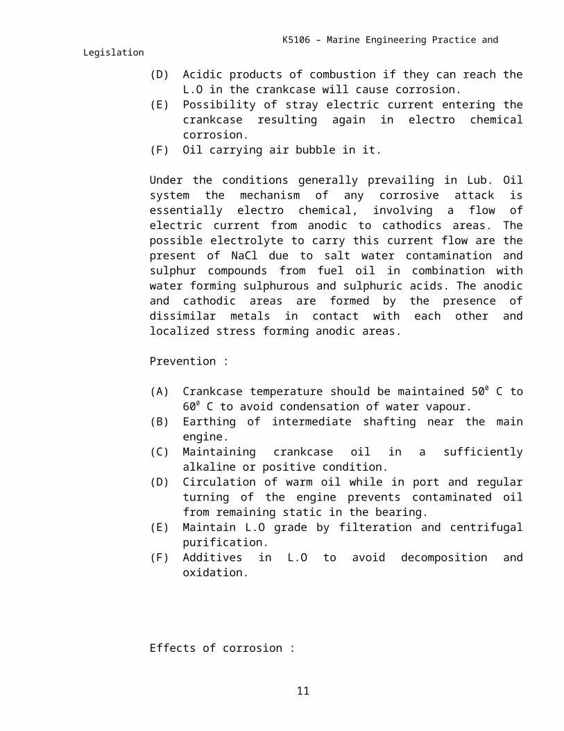
(A)Pitting of shaft will cause stress concentration.(B) Corrosion fatigue failure.(C) In service the metal resulting from corrosion are
Carried by L.O in the system. They lead to scoring,Increased wear of journal, crankpin and bearings.
(D) Ultimate failure.
CRANKSHAFT DEFLECTION :
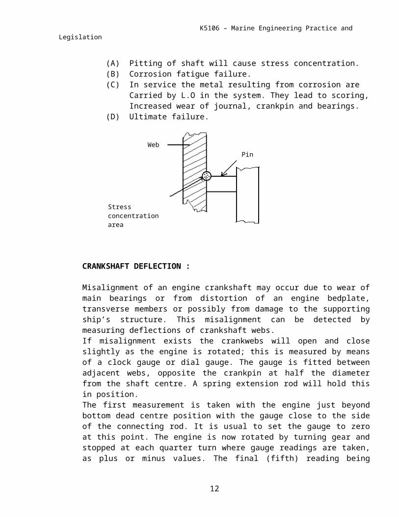
Misalignment of an engine crankshaft may occur due to wear of main bearings or from distortion of an engine bedplate, transverse members or possibly from damage to the supporting ship’s structure. This misalignment can be detected by measuring deflections of crankshaft webs.If misalignment exists the crankwebs will open and close slightly as the engine is rotated; this is measured by means of a clock gauge or dial gauge. The gauge is fitted between adjacent webs, opposite the crankpin at half the diameter from the shaft centre. A spring extension rod will hold this in position.The first measurement is taken with the engine just beyond bottom dead centre position with the gauge close to the side of the connecting rod. It is usual to set the gauge to zero at this point. The engine is now rotated by turning gear and stopped at each quarter turn where gauge readings are taken, as plus or minus values. The final (fifth) reading being taken near bottom centre, with the connecting rod on the opposite side of the gauge to the first reading. The first and last readings are averaged to use as an approximation for bottom centre position. This procedure is repeated for each unit in turn. Feeler gauges should be used to ascertain that the crankshaft has not lifted or sprung in adjacent main bearings.It may be advisable to rotate turning gear slightly in reverse direction when stopping for readings, this will ensure free positioning of the cranks. This is particularly so for units adjacent to the turning gear.
9
Stress concentrationarea
WebPin
K5106 – Marine Engineering Practice and Legislation
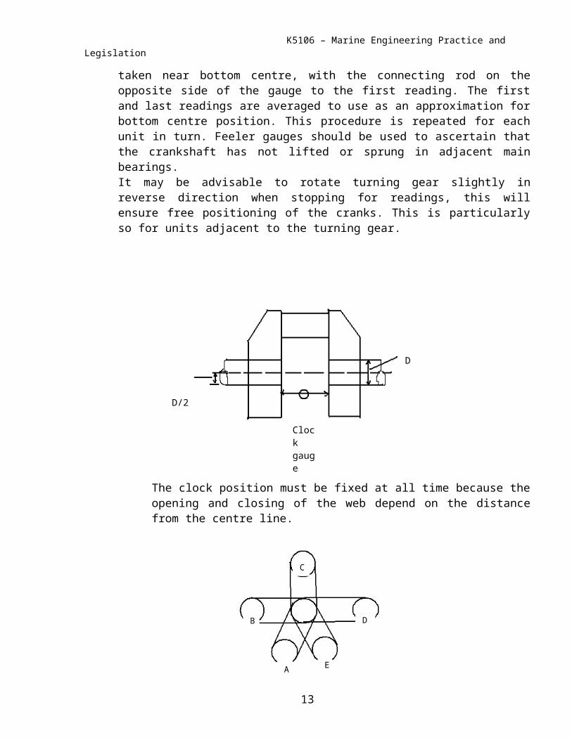
The clock position must be fixed at all time because the opening and closing of the web depend on the distance from the centre line.
Position of A & E must be as closed as possible to the BDC.
CYLINDER NUMBER 1 2 3 4 5 6CRANK POSITION ACRANK POSITION BCRANK POSITION CCRANK POSITION D
EQUIVALENT
VERTICAL DEFLECTION
HORIZONTAL DEFLECTION B – D
FIG. 41 RECORD OF DEFLECTIONS
All readings are recorded and these should be compared with previous values, preferably with the ship in a similar load condition and at similar temperature.The total deflection vertically and horizontally is calculated for each crank. The vertical load will be proportional to misalignment between the bearings due to wear down. The horizontal total indicates side wear in the bearings.
10
Clockgauge
D
D/2
A
B
C
D
E
K5106 – Marine Engineering Practice and Legislation
By plotting all vertical deflections for the whole engine it is possible to obtain information as to which main bearings are ‘high’ and which are ‘low’. This may be assisted by bridge gauge readings from the bearings but these do not take possible distortion of the bedplate into account.Limiting values for the maximum deflection are set by engine builders. These depend upon the stiffness of crankshaft, engine stroke bore ratio, etc. They indicate the limits to which misalignment may be permitted before remetalling of bearings and realignment are necessary.Deflection measurements are readily taken and they relate directly to misalignment. They should be taken at regular intervals or at other times when damage to the running gear in the crankcase, propeller, shafting, or ship’s structure is suspected.Excessive misalignment will cause bending of the crankshaft and webs with fluctuating and alternating stresses causing fatigue and possibility of shaft failure. It will set up vibrations and cause damage to main bearings
11
K5106 – Marine Engineering Practice and Legislation
MATHOD OF CHECKING CRANKSHAFT ALIGNMENT
Crankshaft alignment can be checked by taking deflection.
12
Central load WGauge reading negative
W
Central load WGauge reading positive
W
K5106 – Marine Engineering Practice and Legislation
METHOD OF TESTING ALIGNMENT
1. Used bridge gauge.2. Measure thickness of bottom half shell.3. Crank deflection measurement.
When bearing between 2 crank is high, both crank webs open-out at BDC.They close-in at TDC.
13
Norrnal height
Bearing high
TDC
BDC