Cracking Intel Sandy Bridge’s Cache Hash Function - arXiv · On Sandy Bridge processor, LLC is...
13
Cracking Intel Sandy Bridge’s Cache Hash Function Zhipeng Wei, Zehan Cui, Mingyu Chen Insitute of Computing Technology, Chinese Academy of Sciences {weizhipeng, cuizehan, cmy}@ict.ac.cn Abstract—On Intel Sandy Bridge processor, last level cache (LLC) is divided into cache slices and all physical addresses are distributed across the cache slices using an hash function. With this undocumented hash function existing, it is impossible to implement cache partition based on page coloring. This article cracks the hash functions on two types of Intel Sandy processors by converting the problem of cracking the hash function to the problem of classifying data blocks into different groups based on eviction relationship existing between data blocks that are mapped to the same cache set. Based on the cracking result, this article proves that it’s possible to implement cache partition based on page coloring on cache indexed by hashing. I. I NTRODUCTION Cache plays an important role in bridging the gap between the speed of processor and main memory. Many cache architectures have been proposed in history. Hash is an important technique to improve cache performance, such as hash-rehash cache. As the succeeding generation to Nehalem, one of Sandy Bridge processor’s new fea- tures is that LLC is divided into several slices which are connected by a ring bus, as shown in Figure 1. And the location of a given data block on LLC is decided by an undocumented hash function. This article proposes a novel method using HMTT [1] to crack the hash function and further verifies the cor- rectness of the cracking result based on the phenomenon that when the number of accessed data blocks that are mapped to the same cache set exceeds the associativity of cache set, average access latency increases sharply. Compared to the statement that page coloring doesn’t work on caches that are indexed using hashing [5], this articles ported User Level Cache Control, which is a soft- ware runtime library used to improve cache performance by implementing cache partition based on page coloring, and proves hat it is possible to implement cache partition using page coloring on Intel Sandy Bridge processors. This articles has the following contributions: (1) ver- ifying that bit substring of physical address is used to select cache sets and that it is possible to partition cache capacity based on set index; (2) cracking hash function on Sandy Bridge 4 core processor and further the hash function to a simple function formula; (3) cracking hash function on Sandy Bridge 6 core processor and presents the hash function in the form of 32 mapping tables. As different set indexes correspond to different mapping relationship, attentional attention are needed when designing the page coloring mechanism. However, because it’s true that bit substring of physical address is used to select cache sets, although the hash function hasn’t been reduced to a simple formula, it’s still possible to implement cache partition based on cache set index. DMI PCIe IMC Cores L1 & L2 Cache L3 Cache Ring Bus Fig. 1: LLC organization on Intel Sandy processor. This article is organized as follows: Section 2 defines the problem. Section 3 describes the procedure to crack cache hash function. Section 4 presents the observations based on which this article comes up with the assumption about the implementation of the hash function. Section 5 describes the assumptions about the implementations of the hash function. Section 6 presents the details of the cracking scheme. Section 7 presents the cracking results. Section 8 describes the details to verify the correctness of the cracking result. Section 9 describes the results of performance of cache partition implemented based on page coloring. Section 10 summarizes the contributions. II. PROBLEM All the physical memory is divided into data blocks, and the size of data block is the same with the size of cache line. arXiv:1508.03767v1 [cs.OH] 15 Aug 2015
Transcript of Cracking Intel Sandy Bridge’s Cache Hash Function - arXiv · On Sandy Bridge processor, LLC is...
Cracking Intel Sandy Bridge’s Cache Hash FunctionZhipeng Wei, Zehan Cui, Mingyu Chen
Insitute of Computing Technology, Chinese Academy of Sciences{weizhipeng, cuizehan, cmy}@ict.ac.cn
Abstract—On Intel Sandy Bridge processor, last levelcache (LLC) is divided into cache slices and all physicaladdresses are distributed across the cache slices usingan hash function. With this undocumented hash functionexisting, it is impossible to implement cache partition basedon page coloring. This article cracks the hash functionson two types of Intel Sandy processors by converting theproblem of cracking the hash function to the problemof classifying data blocks into different groups based oneviction relationship existing between data blocks that aremapped to the same cache set. Based on the crackingresult, this article proves that it’s possible to implementcache partition based on page coloring on cache indexedby hashing.
I. INTRODUCTION
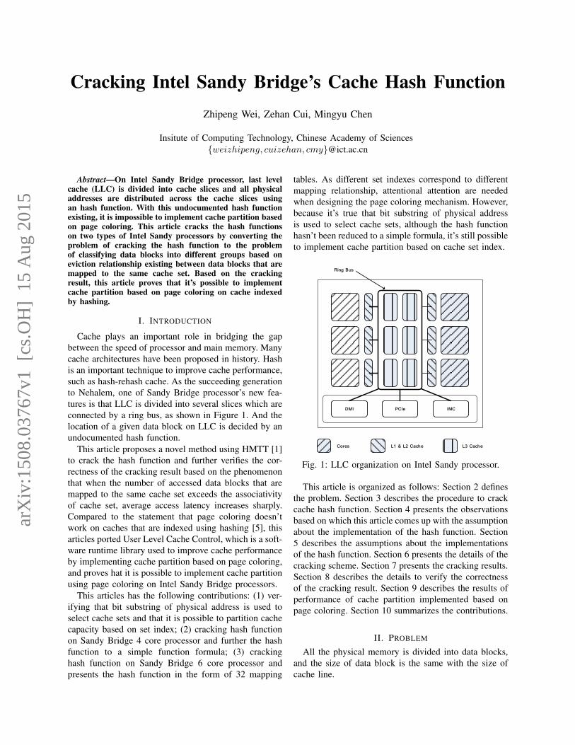
Cache plays an important role in bridging the gapbetween the speed of processor and main memory. Manycache architectures have been proposed in history. Hashis an important technique to improve cache performance,such as hash-rehash cache. As the succeeding generationto Nehalem, one of Sandy Bridge processor’s new fea-tures is that LLC is divided into several slices which areconnected by a ring bus, as shown in Figure 1. And thelocation of a given data block on LLC is decided by anundocumented hash function.
This article proposes a novel method using HMTT [1]to crack the hash function and further verifies the cor-rectness of the cracking result based on the phenomenonthat when the number of accessed data blocks that aremapped to the same cache set exceeds the associativityof cache set, average access latency increases sharply.Compared to the statement that page coloring doesn’twork on caches that are indexed using hashing [5], thisarticles ported User Level Cache Control, which is a soft-ware runtime library used to improve cache performanceby implementing cache partition based on page coloring,and proves hat it is possible to implement cache partitionusing page coloring on Intel Sandy Bridge processors.
This articles has the following contributions: (1) ver-ifying that bit substring of physical address is used toselect cache sets and that it is possible to partition cachecapacity based on set index; (2) cracking hash functionon Sandy Bridge 4 core processor and further the hashfunction to a simple function formula; (3) crackinghash function on Sandy Bridge 6 core processor andpresents the hash function in the form of 32 mapping
tables. As different set indexes correspond to differentmapping relationship, attentional attention are neededwhen designing the page coloring mechanism. However,because it’s true that bit substring of physical addressis used to select cache sets, although the hash functionhasn’t been reduced to a simple formula, it’s still possibleto implement cache partition based on cache set index.
DMI PCIe IMC
Cores L1 & L2 Cache L3 Cache
Ring Bus
Fig. 1: LLC organization on Intel Sandy processor.
This article is organized as follows: Section 2 definesthe problem. Section 3 describes the procedure to crackcache hash function. Section 4 presents the observationsbased on which this article comes up with the assumptionabout the implementation of the hash function. Section5 describes the assumptions about the implementationsof the hash function. Section 6 presents the details of thecracking scheme. Section 7 presents the cracking results.Section 8 describes the details to verify the correctnessof the cracking result. Section 9 describes the results ofperformance of cache partition implemented based onpage coloring. Section 10 summarizes the contributions.
II. PROBLEM
All the physical memory is divided into data blocks,and the size of data block is the same with the size ofcache line.
arX
iv:1
508.
0376
7v1
[cs
.OH
] 1
5 A
ug 2
015
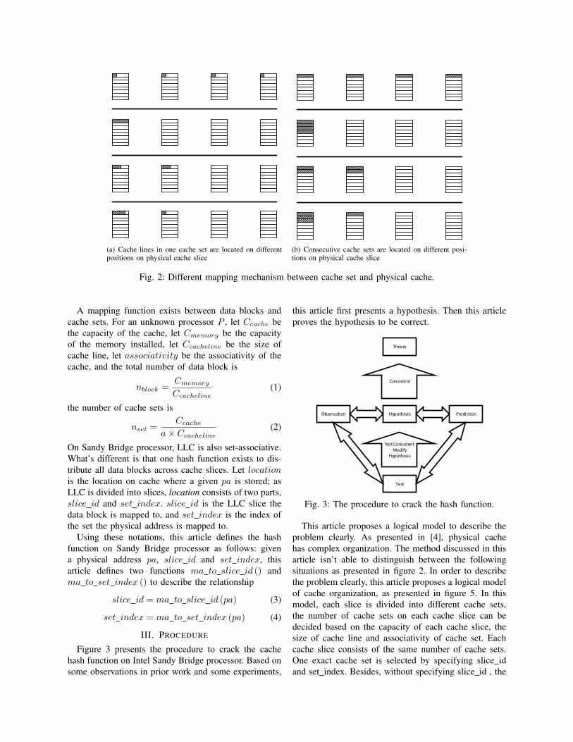
(a) Cache lines in one cache set are located on differentpositions on physical cache slice
(b) Consecutive cache sets are located on different posi-tions on physical cache slice
Fig. 2: Different mapping mechanism between cache set and physical cache.
A mapping function exists between data blocks andcache sets. For an unknown processor P , let Ccache bethe capacity of the cache, let Cmemory be the capacityof the memory installed, let Ccacheline be the size ofcache line, let associativity be the associativity of thecache, and the total number of data block is
nblock =Cmemory
Ccacheline(1)
the number of cache sets is
nset =Ccache
a× Ccacheline(2)
On Sandy Bridge processor, LLC is also set-associative.What’s different is that one hash function exists to dis-tribute all data blocks across cache slices. Let locationis the location on cache where a given pa is stored; asLLC is divided into slices, location consists of two parts,slice id and set index. slice id is the LLC slice thedata block is mapped to, and set index is the index ofthe set the physical address is mapped to.
Using these notations, this article defines the hashfunction on Sandy Bridge processor as follows: givena physical address pa, slice id and set index, thisarticle defines two functions ma to slice id () andma to set index () to describe the relationship
slice id = ma to slice id (pa) (3)
set index = ma to set index (pa) (4)
III. PROCEDURE
Figure 3 presents the procedure to crack the cachehash function on Intel Sandy Bridge processor. Based onsome observations in prior work and some experiments,
this article first presents a hypothesis. Then this articleproves the hypothesis to be correct.
Theory
Observation Hypothesis Prediction
Test
Not Consistent Modify
Hypothesis
Consistent
Fig. 3: The procedure to crack the hash function.
This article proposes a logical model to describe theproblem clearly. As presented in [4], physical cachehas complex organization. The method discussed in thisarticle isn’t able to distinguish between the followingsituations as presented in figure 2. In order to describethe problem clearly, this article proposes a logical modelof cache organization, as presented in figure 5. In thismodel, each slice is divided into different cache sets,the number of cache sets on each cache slice can bedecided based on the capacity of each cache slice, thesize of cache line and associativity of cache set. Eachcache slice consists of the same number of cache sets.One exact cache set is selected by specifying slice idand set index. Besides, without specifying slice id , the

Array size (MB)
8 16 24 32 40 48 56 64 72 80 88 96 104
112
120
128
136
144
152
160
Average Latency (ns)
0
20
40
60
80
100
120
stride = 64 Bstride = 128 Bstride = 256 Bstride = 512 Bstride = 1 KBstride = 2 KBstride = 4 KBstride = 8 KBstride = 16 KBstride = 32 KBstride = 64 KB
(a) Stride varies from 64B to 64KB.
Array size (MB)
8 16 24 32 40 48 56 64 72 80 88 96 104
112
120
128
136
144
152
160
Average Latency (ns)
0
20
40
60
80
100
120
140
160
stride = 128 KB stride = 256 KB stride = 512 KB stride = 1024 KB
(b) Stride varies from 128KB to 1024KB
Array size (MB)
32 64 96 128
160
192
224
256
288
320
352
384
416
448
480
512
544
576
608
640
672
704
736
768
800
832
864
896
928
960
992
Average Latency (ns)
0
20
40
60
80
100
120
140
160
180
200
stride = 2 MB stride = 4 MB stride = 8 MB stride = 16 MB
(c) Stride varies from 2MB to 16MB.
Array size (MB) #104
0.10
24
0.20
48
0.30
72
0.40
96
0.51
2
0.61
44
0.71
68
0.81
92
0.92
16
1.02
4
1.12
64
1.22
88
1.33
12
1.43
36
1.53
6
1.63
84
1.74
08
1.84
32
1.94
56
2.04
8
2.15
04
2.25
28
2.35
52
2.45
76
2.56
2.66
24
2.76
48
2.86
72
2.96
96
3.07
2
3.17
44
3.27
68
Average Latency (ns)
20
40
60
80
100
120
140
160 stride = 32 MB stride = 64 MB stride = 128 MB stride = 256 MB
(d) Stride varies from 32MB to 256MB.
Fig. 4: Perform data dependent access with different stride. For each stride, there is a point that when the averageaccess latency begins to increase sharply.
cache sets with the same set indexon each cache slicewill be selected.
Index – 11bits of fset – 6bitstag – 19bits
set 0
set 2047
set 0
set 2047
set 0
set 2047
set 0
set 2047
set 0
set 2047
set 0
set 2047
Ma_to_slice_id()
Physical address
Fig. 5: Logical model about Intel Sandy Bridge LLCorganization.
IV. OBSERVATION
A. Main memory and LLC access latency
When the data accessed can’t be held in cache, cachemiss will cause average access latency to increase.
B. Substring of physical address serves as set index
As described in section methodology, the test programis able to access data blocks in specified cache sets. Thisarticle first accesses the physical memory with differentstride, and the size of physical memory and the strideis recorded. Besides, when the number of accessed datablocks exceeds the number of the selected cache sets,serious conflict will cause average access latency toincrease sharply.
As presented in figure 4, average access latency in-creases sharply at one point. This point represents theconfiguration of the test, including array size and stride.
Table 1. The number of cache lines that reside in cache whenaccessing using different stride and array size.
stride number stride number
64B 15× 214 32KB 15× 25
128B 15× 213 64KB 15× 24
256B 15× 212 128KB 15× 23
512B 15× 211 256KB 15× 23
1KB 15× 210 512KB 15× 23
2KB 15× 29 1MB 15× 23
4KB 15× 28 2MB 15× 23
8KB 15× 27 4MB 15× 23
16KB 15× 26 8MB 15× 23
With each configuration, the number of data blocksaccessed is decided by array size and stride. As shown infigure 1, when the stride is larger than 32KB, the numberof cache lines LLC can hold equals to 120. Chances arethat some bits in physical address serves as set indexduring cache access. When the stride is large enough,the set index will remain unchanged for the data blocksaccessed. Considering the fact that the associativity ofthe Sandy Bridge processor in this test is 20, and has6× 20 = 120 cache sets.
C. The hash function meets some properties
As presented in [6], the set-associative organizationcache should meet the following properties to providebetter performance. (1) Equitability; (2) Local disper-sion; (3) Simple hardware implementation;

Table 2. Processor parameters.
CPU Type Intel R©Xeon R©Processor E5-2640 Intel R©Xeon R©Processor E5-2603
Intel CPU core 6 [email protected] 4 [email protected] I-Cache 32kB/core, 8-way, 64B line 32kB/core, 8-way, 64B lineL1 I-Cache 32kB/core, 8-way, 64B line 32kB/core, 8-way, 64B lineL2 Cache 256kB/core, 8-way, 64B line 256kB/core, 8-way, 64B lineL3 Cache 15360kB(shared, 6 slices); 20-way, 64B line 10240kB(shared, 4 slices); 20-way, 64B lineMemory Capacity 64GB 16GB
V. ASSUMPTION
Let nslice be the total number of slices and nset be thenumber of sets on each slice, (an−1, . . . , a0) be the bi-nary representation of the physical address. As presentedin figure 6, this article splits the binary representation ofan address pa into bit substrings (A2, A1, A0), A0 is a cbit string: the displacement in the line. A1 is a n slicebit string and A2 is the string of the most significant bits.Based on the work presented in [7], this article makesthe following assumptions:
1) the value of A0 is used as block address;2) the value of A1 is used as set index on a specified
cache slice;3) A2 is used to decide the slice id of a given pa;
Physical address
A2 A1 A0
N-1 0
0561617N-1
Fig. 6: Split physical address into different fields.
VI. METHODOLOGY
This section discusses the following three questions:(1) the criteria which is used to classify all the physicaladdresses; (2) the mechanism to ensure the correctnessof the criteria; (3) the method to get the informationneeded to perform the classification of data blocks.
A. Platform
Table 2 presents the parameters of the processors usedin this article.
B. Classifying criteria
Evicting relationship exists between data block s thatare mapped to the same cache set. When the number ofaccessed data blocks exceeds the associativity of cacheset, cache conflict occur, these data block will begin toevict each other, as presented in figure 7. This articleuses this evicting relationship to classify data block intodifferent groups.
C. Getting the evicting relationship between data block
1) Accessing data in desired cache set: In order toget the evicting relationship, the testing program shouldbe able to fill data into specified cache set. We boot theoperating system with 2GB memory. In this way, theOS can only use the lower 2GB memory. This articlefurther implement a driver to map the other physicalmemory ranging from 2GB to 3GB into kernel space. Inthis way, the physical address accessed can be calculatedby subtracting based address from the linear address ofthe operating system.
Table 3. Use combinations of bits to generate addresses
(a) bit a2, a1, a0
Bit value Value
000 0x0
001 0x1
010 0x2
011 0x3
100 0x4
101 0x5
110 0x6
111 0x7
(b) bit a18, a17, a16
Bit value Value
000 0x00000
001 0x10000
010 0x20000
011 0x30000
100 0x80000
101 0x90000
110 0xa0000
111 0xb0000
2) Test sequence generation: As presented in table 3,the physical address is generated by bit combination. Inthis way, this article verifies the effect of every bit onthe result of hash function.
3) Array initialization: The testing program firstlyallocates an array. Then the testing program initializesthe test array in a data-dependent manner, which meansthat the data stored at the current read address is theaddress of the next read command. As shown in Figure 8,the main operation of the test program is to read dataand use the data as the address of the following readoperation.
4) Ensure the correctness of evicting relationship:As depicted in code snippet 2, idle loop is insertedbetween adjacent memory accesses to make sure thatonly two physical addresses with eviction relationshipexists between each other are temporally adjacent.
5) Collecting memory reference trace: HMTT is ahybrid hardware/software memory trace monitoring sys-

Cache Set
Memory
HMTT
Cache Set
HMTT r r r r r r r rrr
Cache Set
Memory
HMTT r r r r r r r rrr
Cache Set
Memory
HMTT r r r r r r r rrr W
Cache Set
Memory
HMTT r r r r r r r rrr W r
1 2
5
3 4
6
Evicting relationship can be extracted from the memory referencing trace that HMTT collects.
r r r r r r r rrr W r
W r
All trace
Evicting relationship extracted from all trace
Memory
Fig. 7: Extract evicting relationship between data block from memory reference trace that HMTT collects: (1) Thearray is initialized in a data dependent manner; (2) associativity data blocks are read into cache; (3) the next datablock is going to be read; (4) one cache line is evicted before the next data block can be read into cache; (5) nextdata block is read into cache.
whi le ( j < i t e r a t i o n ) {add r = ∗ (TYPE∗ ) ( add r ) ;j ++;
}
Listing 1: The main opration of test program withoutinterval between consecutive acesses.
whi le ( j < i t e r a t i o n ) {add r = ∗ (TYPE∗ ) ( add r ) ;/ / mo d i f y t h e cache l i n e∗ (TYPE∗ ) ( add r +16) = 1 ;whi le ( k++ < 1 0 0 0 ) ;j ++;k =0;
}
Listing 2: The main opration of test program withinterval between consecutive acesses.
tem. This tool collects all the memory reference trace,which memory controller issues to memory modules.
Although the tool can be programmed to collect variousinformation [2], the information needed in this articleincludes physical address, time interval between differentconsecutive physical addresses and read/write bit of thephysical address, as presented in table 4. The wholeprocess is presented in figure 7. When the cache setis full and testing program reads another data blockinto cache, one of the data blocks already read intocache needed to be evicted to make room for the newlyread data block. The two operations are collected byHMTT and save as two memory reference trace. Thetrace consists of information about the address of theoperation and whether the operation is read or write.
6) Classify all the physical address into differentgroups: As presented in figure 9(b), if evicting rela-tionship exists between physical address A and B, andalso exists between physical address B and C, then it isconcluded that evicting relationship also exists betweenphysical address B and C. This article further classifiesall the physical addresses into different groups based onconnected subgraph related method.

Table 4. Sample memory reference trace.
Seq Read or Write Physical Address Interval
1 read bfd60000 15
2 write be1a0000 1094
3 read bfd80000 15
4 write be4a0000 608
5 read bfda0000 9
6 write be500000 1206
7 read bfdc0000 20
8 write bef40000 1090
AddrssMake dirty
field
100
111
0
1
1012
110
010
3
4
0015
0006
0117
8 bytes
64 bytes
Cyclic access entry point
64 byte elementIndex
Fig. 8: The test array is initialized using shuffled ad-dresses in a data-dependent manner.
VII. RESULTS
This article presents the mapping relationship in theform of mapping table. It’s true with both Sandy Bridge4 core and 6 core processor that bit string A1 in physicaladdress selects cache set directly. For both processor,there are nset cache sets per cache slice. The number ofdata blocks that are mapped to cache set with the sameset index is
Cmemory
Cdatablock × nset(5)
Let Cmemory be the installed memory, let Ccapacity thesize of data block, and let nblock be total number of datablocks, due to the fact that, as presented in figure 10(a),substring A1 in physical address is used to select cacheset, for those data blocks those share the same set index,they will be mapped to cache sets on all cache slicesharing the same cache set index, the total number ofcache slice is nslice. For those blocks sharing the sameset index, this article uses a mapping table to describethe relationship.
A. 4 core processor
On Sandy Bridge 4 core processor, the installed mem-ory is 16GB, so the total data block is
nblock =Cmemory
Ccapacity=
16GB
64B= 228 (6)
The number of cache sets on each cache slice is 2048,the number of data block that share the same cache setindex is
nblock
nset=
228
211= 217 (7)
These data blocks will be mapped to these selectedcache sets. As presented in table 6, as all the blocksshare the same set index, this article only presents theA2 string of each block address here. Each set indexcorresponds to a mapping table. This article finds that onIntel 4 core processor, the mapping tables correspondsto different set index are the same.
The installed physical memory is 16GB, so we havethe mapping table of 34 bit width physical address.Because bit string A1 in physical address selects cacheset directly, there are 2048 cache sets on each cache slice.As a result, there should have been 2048 mapping tableto describe the relationship. However, this article findsthat the mapping table is the same for all set index.
Reduction of Sandy Bridge processor mapping table.The mapping table can be reduced to a simple formula.As presented in figure 10(b), two intermediate value 5,bit a0, bit a1, these four value is related to four differ-ent cache slices. The value of bit16bit15 is used to selectone set from from four cache sets selected by set indexof the data block.
B. 6 core processor
On Sandy Bridge 6 core processor, the installed mem-ory is 64GB, so the total data block is
nblock =Cmemory
Cdatablock=
64GB
64B= 230 (8)
Because there are 2048 cache sets on each slice, thenumber of data block sharing the same cache set indexis
nblock
nset=
230
211= 219 (9)
However, on 6 core processor, cache set with differentcache set index might have different mapping table.There are 2048 cache set on each set index. As a result,there exist 2048 mapping tables corresponding to 2048set indexes. After further analysis, this article has testedevery set index with 1GB physical memory (30 bitsphysical address). As presented in table 8, the resultshows that the mapping table of some set indexes arethe same. Set index 0, 2, 65, 67 share the same mappingtable. And There are 32 different mapping table. Setindex ranging from 0 to 2047 fall into 32 mapping tables.
Higher physical address bits also affect the result ofhash function. On Sandy Bridge 6 core processor, thisarticle has verified each set index with 1GB physicalmemory. Let (an−1, . . . , a0) be the binary representation

bit a0 = get bit (A2, 0) ⊕ get bit (A2, 1) ⊕ get bit (A2, 2) ⊕ get bit (A2, 3) ⊕ get bit (A2, 4) ⊕get bit (A2, 5) ⊕ get bit (A2, 7) ⊕ get bit (A2, 9) ⊕ get bit (A2, 10) ⊕ (get bit (A2, 12) &
get bit (A2, 14)) ⊕ ( (∼ get bit (A2, 14)) & get bit (A2, 13) )
bit a1 = get bit (A2, 0) ⊕ get bit (A2, 2) ⊕ get bit (A2, 4) ⊕ get bit (A2, 6) ⊕ get bit (A2, 8) ⊕get bit (A2, 10) ⊕ get bit (A2, 11) ⊕ get bit (A2, 13) ⊕(get bit (A2, 14) & get bit (A2, 13) & get bit (A2, 12))
Table 5. Two intermediate value used to reduce Sandy Bridge 4 core mapping table.
(a) Breadth first search. (b) Represent data block with a node, and Representevicting relationship with an edge.
(c) The data blocks are classified into different groups.
Fig. 9: This article uses connected subgraph method to solve the problem of classifying data block .
Physical address
A2 A1 A0
33 0
056161733
B1
1933
B0
1718
(a) Figure A
A2 (bit_a1, bit_a0)
hash_tag3 hash_tag2 hash_tag1 hash_tag0
slice3 slice2 slice1 slice0
n
(~bit_a1, ~bit_a0) (~bit_a1, bit_a0) (bit_a1, ~bit_a0) (bit_a1, bit_a0)
B0
1 2
3
(b) Figure B
Fig. 10: Intel Sandy Bridge 4 core processor hash fucntion cracking result.
Fig. 11: The physical addresses sharing the same setindex are divided into into six groups using Cytoscape.
of physical address, with 1GB physical memory tested,this article gets the result of bits (a29, . . . , a0). When itcomes to the higher address bits (a35, . . . , a30), this arti-cle verifies with 64GB(36 bits physical address) physicalmemory. The result shows the higher bits also affects theresult of hash function. However, the data blocks sharingthe same set index can still be split into 6 groups. Thismeans that substring A2 is used to select the slice id ofa given pa.
VIII. VERIFICATION OF THE CORRECTNESS OF THECRACKING RESULT OF SANDY BRIDGE CACHE HASH
FUNCTION
A. Object of correctness verification
This article proposes a method to verify the correct-ness of the cracking result. The cracked function will

Table 6. 4 core cache hash mapping table
Slice 0 Slice 1 Slice 2 Slice 3
4000 4001 4002 4003
4007 4006 4005 4004
4009 4008 400b 400a
400e 400f 400c 400d
4013 4012 4011 4010
4014 4015 4016 4017
401a 401b 4018 4019
401d 401c 401f 401e
4021 4020 4023 4022
4026 4027 4024 4025
4028 4029 402a 402b
402f 402e 402d 402c
4032 4033 4030 4031
4035 4034 4037 4036
403b 403a 4039 4038
403c 403d 403e 403f
map different data blocks to different cache sets. Thisarticle verifies the correctness of the cracking result bychecking that the data blocks that are indicated by thecracking result to be in one cache set are truly in onecache set.
Average access
latency (LLC)
Average access latency
(memory)
Average access
latency (LLC)
LLC Associativity
Cache Set
Accessed sequence of testing program
Cache Set
MRU MRU
Accessed sequence of testing program
Average access latency
(memory)
LLC Associativity
Fig. 12: Replacement policy affects the avearage latency.
Number of data blocks that are accessed
15 16 17 18 19 20 21 22 23 24 25 26 27 28 29 30 31 32 33 34 35 36 37 38 39 40
Execution time (ns)
0
20
40
60
80
100
120
140
160Do not pollute the cache linePollute the cache line
Fig. 13: Replacement policy affects the avearage latency.
As presented in figure 13, average access latency in-creases sharply when the number of data blocks accessedexceeds the associativity of LLC. This is relativelyobvious. This article finds that performing another writeoperation after the data block is read into cache will af-fect cache replacement policy. As presented in figure 13,polluting the cache line means that adding another writeoperation, and do not pollute the cache line meansperform only dependent read operation. It can be seenfrom the figure that performing another read operationcauses the average access latency to increase slowlycompared to the read operation only configuration. Onepossible explanation is as shown figure 12, when a newcache line arrives, if the newly accessed data block isinserted into the MRU position, when the number ofdata blocks accessed exceeds the associativity of LLC,even if only exceeds by one, the average access latencywill increase sharply. The method is able to check everycache set.
Verify the correctness of the cracking result usingtwo threads. In this verifying scenario, use two threadsto perform data dependent access. The average accesslatency is recorded for each configuration. In the firstconfiguration, the data blocks accessed by thread 1 andthe data blocks accessed by thread 2 are mapped todifferent cache sets, the results is presented in figure 15.In the second configuration, the data blocks accessed bythread 1 and the data blocks accessed by thread 2 aremapped to different cache sets, the results is presentedin figure 14. For both configurations, the number of datablocks accessed by thread 2 vary from 1 to 40. And thenumber of data block accessed by thread 1 varies from1 to 4. When the number of data blocks accessed bythread 1 exceeds the associativity, average latency willincrease sharply. When thread 1 performs data dependentaccess on 1 data block, in the first configuration, as thedata blocks accessed by two threads are mapped to thesame cache set and thread 1 accessed 1 data block,average access latency of thread 2 increases sharplywhen the number of accessed data blocks of thread 2 is18; On the contrary, when the data blocks accessed bytwo threads are mapped to different cache sets, averageaccess latency of thread 2 increases sharply when thenumber of accessed data blocks of thread 2 is 18. Thisarticle gets similar results when the number of datablocks access by thread1 varies from 1 to 4.
Write operation has effect on cache replacement pol-icy. In the following test, the program performs datadependent access, two configuration of the program isas follows: (1) when the data block is read, perform awrite operation to make the cache line dirty; (2) do notmake the cache line dirty.
Let Laverage be the average access latency, Lmemory
be the access latency of memory, LLLC be the access

Table 7. Intel Sandy Bridge 6 core processor hash function cracking result.
(a) 6 core cache hash mapping table, set index 1
Slice 0 Slice 1 Slice 2 Slice 3 Slice 4 Slice 5
4000 4001 4002 4003 4007 400e
400d 4006 4005 4004 400a 400f
4017 400c 4008 4009 400b 4014
401a 4016 4012 4013 4010 4015
401d 401b 401f 401e 4011 4018
4023 401c 4026 4027 4024 4019
4029 4022 402b 402a 4025 4020
402e 4028 402c 4030 4032 4021
4034 402f 4031 4037 4033 402d
4039 4035 4036 403d 403e 403a
4041 4038 403c 4042 403f 403b
4046 4040 4043 4045 404c 4044
404b 4047 404e 404f 404d 4048
4051 404a 4054 4055 4056 4049
405c 4050 4059 4058 4057 4052
4065 405d 405e 405f 405a 4053
4068 4064 4060 4061 405b 4066
406f 4069 406a 406b 4062 4067
4072 4073 406d 406c 4063 4070
4075 4074 4077 4076 406e 4071
407f 407e 407a 407b 4078 407c
NULL NULL NULL NULL 4079 407d
(b) 6 core cache hash mapping table, set index 2
Slice 0 Slice 1 Slice 2 Slice 3 Slice 4 Slice 5
4000 4002 4003 4004 4006 4007
4001 4008 4009 4005 400b 400a
400c 400f 400e 4012 4011 4010
400d 4015 4013 401e 4016 4017
401a 4018 4014 401f 401c 401d
401b 4021 4019 4026 4022 4023
402e 402c 4020 4027 4025 4024
402f 4036 402d 402a 4028 4029
4034 403b 4037 402b 4032 4033
4035 403c 403a 4030 403f 4039
4038 4044 403d 4031 4040 403e
4046 4049 4045 4042 404a 4041
4047 4053 4048 4043 404d 404b
4051 4054 4052 404e 4050 404c
405c 405e 4055 404f 4057 4056
405d 4060 405f 4058 405a 405b
4064 4067 4061 4059 4063 4062
4065 406a 4066 406c 406e 406f
4068 4070 406b 406d 4074 4075
4069 407a 4071 4076 4079 4078
4072 407d 407c 4077 407e 407f
4073 NULL NULL NULL 407b 407d
Table 8. Mapping table corresponding to set index ranging from 0 to 127 shares 32 different mapping table. The situation isthe same for set index ranging from 128 to 2047.
Mapping table index Index Index Index Index Mapping table index Index Index Index Index
1 0 2 65 67 17 32 34 97 99
2 1 3 64 66 18 33 35 96 98
3 4 6 69 71 19 36 38 101 103
4 5 7 68 70 20 37 39 100 102
5 8 10 73 75 21 40 42 105 107
6 9 11 72 74 22 41 43 104 106
7 12 14 77 79 23 44 46 109 111
8 13 15 76 78 24 45 47 108 110
9 16 18 81 83 25 48 50 113 115
10 17 19 80 82 26 49 51 112 114
11 20 22 85 87 27 52 54 117 119
12 21 23 84 86 28 53 55 116 118
13 24 26 89 91 29 56 58 121 123
14 25 27 88 90 30 57 59 120 122
15 28 30 93 95 31 60 62 125 127
16 29 31 92 94 32 61 63 124 126

Number of data blocks that are accessed
1 2 3 4 5 6 7 8 9 10 11 12 13 14 15 16 17 18 19 20 21 22 23 24 25 26 27 28 29 30 31 32 33 34 35 36 37 38 39 40
Latency (ns)
0
20
40
60
80
100
120
140
160
180
200
220Thread 1Thread 2
(a) Thread 1 accesses 1 data block.
Number of data blocks that are accessed
1 2 3 4 5 6 7 8 9 10 11 12 13 14 15 16 17 18 19 20 21 22 23 24 25 26 27 28 29 30 31 32 33 34 35 36 37 38 39 40
Latency (ns)
0
20
40
60
80
100
120
140
160
180
200 Thread 1Thread 2
(b) Thread 1 accesses 2 data blocks.
Number of data blocks that are accessed
1 2 3 4 5 6 7 8 9 10 11 12 13 14 15 16 17 18 19 20 21 22 23 24 25 26 27 28 29 30 31 32 33 34 35 36 37 38 39 40
Latency (ns)
0
20
40
60
80
100
120
140
160
180
200Thread 1Thread 2
(c) Thread 1 accesses 3 data blocks.
Number of data blocks that are accessed
1 2 3 4 5 6 7 8 9 10 11 12 13 14 15 16 17 18 19 20 21 22 23 24 25 26 27 28 29 30 31 32 33 34 35 36 37 38 39 40
Latency (ns)
0
20
40
60
80
100
120
140
160
180
200
Thread 1Thread 2
(d) Thread 1 accesses 4 data blocks.
Fig. 14: The data blocks accessed by two threads are mapped into the same cache set.
Number of data blocks that are accessed
1 2 3 4 5 6 7 8 9 10 11 12 13 14 15 16 17 18 19 20 21 22 23 24 25 26 27 28 29 30 31 32 33 34 35 36 37 38 39 40
Late
ncy
(ns)
0
20
40
60
80
100
120
140
160
180
200
220Thread 1Thread 2
(a) Thread 1 accesses 1 data block.
Number of data blocks that are accessed
1 2 3 4 5 6 7 8 9 10 11 12 13 14 15 16 17 18 19 20 21 22 23 24 25 26 27 28 29 30 31 32 33 34 35 36 37 38 39 40
Late
ncy
(ns)
0
20
40
60
80
100
120
140
160
180
200
220
Thread 1Thread 2
(b) Thread 1 accesses 2 data blocks.
Number of data blocks that are accessed
1 2 3 4 5 6 7 8 9 10 11 12 13 14 15 16 17 18 19 20 21 22 23 24 25 26 27 28 29 30 31 32 33 34 35 36 37 38 39 40
Late
ncy
(ns)
0
20
40
60
80
100
120
140
160
180
200 Thread 1Thread 2
(c) Thread 1 accesses 3 data blocks.
Number of data blocks that are accessed
1 2 3 4 5 6 7 8 9 10 11 12 13 14 15 16 17 18 19 20 21 22 23 24 25 26 27 28 29 30 31 32 33 34 35 36 37 38 39 40
Late
ncy
(ns)
0
20
40
60
80
100
120
140
160
180
200Thread 1Thread 2
(d) Thread 1 accesses 4 data blocks.
Fig. 15: The data blocks accessed by two threads are mapped into two different cache set.
latency of LLC, N be the associativity of LLC, n bethe number of data blocks that are accessed sequentiallyby the testing program, then the relationship betweenaverage access latency and the number of data blocksaccessed can be describes as:
Laverage =
{LLLC , if n < N
Lmemory(nN − 1) + LLLC , if n ≥ N
(10)Memory reference trace collected with HMTT offers a
different prospective on cache replacement policy. Thisarticle further analyzes the trace: cut a segment of thewhole trace, and count how many times each data blockis accessed in this segment of trace (or this period of
execution). As presented in figure 16, without pollutingthe cache line, for simplicity, label each data blockaccessed with an index, the access number of each datablock is uniform. However, when perform an extra writeoperation to pollute the cache line, the access number ofdifferent data blocks becomes non-uniform, which meansthat some of the data blocks are held in cache longer thanthe other part of data blocks. This fact reveals the factthat write operation affects the cache replacement policy.
IX. ULCC
User Level Cache Control (ULCC) [3] is a softwarepackage to implement cache partition using page color-ing. It improves performance of multi-threaded program

Data Block Index0 1 2 3 4 5 6 7 8
Access count
0
1
2
Make cache line dirtyDo not make cache line dirty
(a) 18 addresses
Data Block Index0 1 2 3 4 5 6 7 8 9 10 11 12 13 14 15 16 17 18 19
Access count
0
10
20
30
40
50
60 Make cache line dirtyDo not make cache line dirty
(b) 19 addresses
Data Block Index0 1 2 3 4 5 6 7 8 9 10 11 12 13 14 15 16 17 18 19 20
Access count
#104
0
1
2
3
4Make cache line dirtyDo not make cache line dirty
(c) 20 addresses
Data Block Index0 1 2 3 4 5 6 7 8 9 10 11 12 13 14 15 16 17 18 19 20 21
Access count
#104
0
1
2
3
4Make cache line dirtyDo not make cache line dirty
(d) 21 addresses
Data Block Index0 1 2 3 4 5 6 7 8 9 10 11 12 13 14 15 16 17 18 19 20 21 22
Access count
#104
0
1
2
3
4Make cache line dirtyDo not make cache line dirty
(e) 22 addresses
Data Block Index0 1 2 3 4 5 6 7 8 9 10 11 12 13 14 15 16 17 18 19 20 21 22 23
Access count
#104
0
1
2
3
4Make cache line dirtyDo not make cache line dirty
(f) 23 addresses
Data Block Index0 1 2 3 4 5 6 7 8 9 10 11 12 13 14 15 16 17 18 19 20 21 22 23 24
Access count
#104
0
1
2
3
4Make cache line dirtyDo not make cache line dirty
(g) 24 addresses
Fig. 16: When test program performs data dependent access of different number of data blocks, the access numberdistribution of different data blocks in a period of time.
by enforcing a user demand cache capacity allocation.By modifying the macro that extracts page color fromphysical address, this article ported ULCC to Intel Sandyprocessor.
A. MergeSort
MergeSort is implemented in multiple threads. Duringthe execution of program, the intermediate result of everyblock is highly reused. ULCC improves the performanceby allocating different cache capacity for data of differ-ent reuse degree.
The performance of the program with and without
Blocking Size (KB)14
336
1638
4
1843
2
2048
0
2252
8
Execution time (s)
0
0.2
0.4
0.6
0.8
1
1.2
1.4
1.6
1.8
2
2.2 Implementation w/ ULCCImplementation w/o ULCC
Fig. 17: The execution time of MergeSort implementa-tions with and without ULCC support.

ULCC support is depicted in figure 17. When choosingsize of sorting block properly, the execution time isreduced by 20%. The result is using one thread tofinish merge sort. So the performance gain is only frompreventing cache pollution of data in one thread.
B. MatMul
The MatMul program multiplies two double precisionmatrices A and B, and produces the product matrix C.To achieve necessary data reuse in LLC, the matrixmultiplication is carried out block by block. For theblock a on the ith block row and jth block column ofmatrix A, it is multiplied with all the blocks on the jthblock row of matrix B, and the results are accumulatedinto the blocks on the ith block row of matrix C. Sothe data in matrix A is of high reuse degree and beforethe program finishes the computation with block a, itis desirable that the data in a can be kept in the cache.However, without a dedicated space for block a, the datain it may be repeatedly evicted from the cache beforeits next use every time the program switches blocks inmatrix B and matrix C, even with a rather small blocksize. To reduce the chance that the data in each block ofmatrix A is evicted from the last level cache prematurely,the size of sorting block should has a most suitable size.
The performance of the program with and withoutULCC support is depicted in figure 18. When choosedata block element properly to make sure that thefrequently used data can be held in cache, this articleachieves the same performance improvement as pre-sented in [3]. This further proves the correctness of thecracking results.
Blocking Size (KB)
510
530
550
570
590
610
630
Execution time (s)
0
10
20
30
40
Implementation w/ ULCCImplementation w/o ULCC
Fig. 18: The execution time of MatMul implementationswith and without ULCC support.
X. GENERAL TEST
This article proposed a method to crack hash functionwithout the support of HMTT. The core of idea is thatwhen the number of accessed addresses exceeds theassociativity of cache set, the average access latency willincrease sharply.
The main procedures of the cracking method withoutsupport of HMTT is as follows: (1) Verify that somebits of physical address are used directly to select cache
set; Divide all data blocks into different groups based onset index; (2) choose associativity data blocks that aremapped to one cache set from the data blocks sharingthe same cache set index,; Access these data blockssequentially, the average access latency will be closeto the access latency of main memory; Put these datablocks in the classified group of data blocks; (3) Chooseassociativity− 1 data blocks from the classified groupand choose one data block from the unclassified group ofdata blocks, perform data dependent access of these datablocks, there are two results: the first is that the averageaccess latency is close to the latency of main memory,and this means that the one data block chosen from theunclassified group of data blocks is mapped to the samecache set with the other associativity − 1 data blocks;the second is that the average access latency is close tothe latency of LLC, and this means that the one datablock chosen from the unclassified group is not mappedto the same cache set with the other associativity − 1data blocks. (4) Perform step 2 and step 3 until all datablocks sharing the same set index have been labeled asclassified or unclassified. (5) Choose another data blockfrom the data blocks which are labeled as unclassified,start again from step 1;
The problem with this method is that it takes too longto finish the test.
XI. CONCLUSIONS
On Intel Sandy Bridge processor, last level cache(LLC) is divided into cache slices and all physicaladdresses are distributed across all cache slices usinga hash function. With this undocumented hash functionexisting, it is impossible to implement cache partitionbased on page coloring.
This article cracks the hash function on two typesof Intel Sandy Bridge processors. It’s true on both 4core and 6 core processors that bit substring of physicaladdress is used to select cache sets. What is differentis that: on Intel Sandy 4 core processor, the mappingrelationship for different cache set indexes is the same.And on Intel Sandy Bridge 4 core processor, the crackedhash function is reduced to a simple formula. On the con-trary, on Intel Sandy Bridge 6 core processor, differentcache set indexes have different mapping relationship.The article has not reduced the hash function to a simpleformula. Instead, the hash function is presented in theform of mapping tables.
This article proves that it’s possible to implementcache partition based on page coloring. On 4 coreprocessor, based on the cracking result, it’s easy toimplement cache partition based on page coloring. On6 core processor, without reducing the hash functionto a simple formula, cache partition can at least be

implemented based on set index, as bit substring ofphysical address is used to select cache sets.
REFERENCES
[1] Y. Bao, M. Chen, Y. Ruan, L. Liu, J. Fan, Q. Yuan, B. Song, andJ. Xu. Hmtt: a platform independent full-system memory tracemonitoring system. ACM SIGMETRICS Performance EvaluationReview, 36(1):229–240, 2008.
[2] L. Chen, Z. Wei, Z. Cui, M. Chen, H. Pan, and Y. Bao.Cmd: classification-based memory deduplication through pageaccess characteristics. In Proceedings of the 10th ACM SIG-PLAN/SIGOPS international conference on Virtual execution en-vironments, pages 65–76. ACM, 2014.
[3] X. Ding, K. Wang, and X. Zhang. Ulcc: a user-level facilityfor optimizing shared cache performance on multicores. In ACMSIGPLAN Notices, volume 46, pages 103–112. ACM, 2011.
[4] Rajeev Balasubramonian. Multicore-Core Cache Hierarchies.Morgan & Claypool, New York, 2011.
[5] D. Sanchez and C. Kozyrakis. Scalable and efficient fine-grainedcache partitioning with vantage. IEEE Micro, (3):26–37, 2012.
[6] A. Seznec. A case for two-way skewed-associative caches. InACM SIGARCH Computer Architecture News, volume 21, pages169–178. ACM, 1993.
[7] H. Wong. Intel ivy bridge cache replacement policy.http://blog.stuffedcow.net/2013/01/ivb-cache-replacement/.


![Evolving Hash Functions using Genetic Algorithmsajiips.com.au/papers/V4.1/V4N1.4 - Evolving Hash Functions using... · hash function called "PKP Hash" by Peter.K.Pearson [5] that](https://static.fdocuments.in/doc/165x107/5e3486a76e7276290f0add90/evolving-hash-functions-using-genetic-evolving-hash-functions-using-hash.jpg)