Crack Depth Determination using Advanced Impact …Principles of vertical crack detection One...
9
Crack Depth Determination using Advanced Impact-Echo Techniques Markus KRÜGER, TTI GmbH – TGU Smartmote, Stuttgart, Germany Christian U. GROSSE, Institute of Construction Materials, Universität Stuttgart, Germany Abstract. Concrete cracking resulting in stiffness loss and also corrosion of the steel reinforcement is an important aspect in reinforced concrete structures. Normally the concrete cover will protect the steel from corrosion. However, if cracks occur and become large the corrosion protection is not given anymore. The corrosion rate strongly depends on the crack width and the crack depth so there is the need to measure and to characterize its dimensions. Only if the crack dimensions exceed a certain level, a repair is necessary. To increase the lifetime of the structure and to optimize the repair this deterioration level has to be known. One way to do this is with the Impact-Echo method. The impact-echo technique is a useful tool for the de- tection of different faults in concrete structures. Unfortunately, the existing instru- ments and analysis tools designed for measurements were lacking of several features in the past detaining the extensive use. For many applications as for inspections of large structures, it is essential that the equipment for Impact-Echo measurements along profiles uses a scanning technique and a fast and reliable data acquisition. A new concept for Impact-Echo testing systems is presented in this paper. Therefore, a new device was developed, which is small and easy to handle, robust and unproblematic regarding transportation. The system utilizes advanced impact generation for fast scanning techniques and reproducible impacts. The data acquisi- tion, filtering and visualization of data are optimized for the inspection of large structures obtaining data at many measurement points. A new option is the auto- matic estimation of crack parameters like crack depth. The crack depth determina- tion is a combination of the well known time-of-flight method with new analysis methods that were made in the time domain. Therefore the acoustic wave and the energy content will be further analysed. In this paper fundamental principles of the different measurement techniques as well as details of the hardware and software functionality of the measurement system are described. Introduction The increasing demands for quality control, defect diagnosis and sustainability of structures in civil engineering leads to a growing market for non-destructive testing. Several methods like ultrasound, radar, thermography, x-rays, electro-potential-field methods and others are currently being used to detect voids, cracks, corrosion, etc. Several years ago, the Impact- Echo (IE) method, that allows the detection of voids and honeycombing in massive struc- tures, was introduced by Carino et al. [1]. Advantageous is the ability to detect failures in structures very fast and to measure the thickness of concrete parts with high accuracy. With the introduction of the guideline RI-ZFP-TU in the year of 2001 the Impact-Echo-technique was chosen as a standard technology for quality control of tunnels in Germany [3]. There- fore, IE together with Impuls-Echo seems to be one of the first non-destructive technologies to be part of a regulating standard for quality control in civil engineering in Germany. ECNDT 2006 - Tu.4.2.2 1
Transcript of Crack Depth Determination using Advanced Impact …Principles of vertical crack detection One...
Crack Depth Determination using Advanced Impact-Echo Techniques
Markus KRÜGER, TTI GmbH – TGU Smartmote, Stuttgart, Germany Christian U. GROSSE, Institute of Construction Materials, Universität Stuttgart, Germany
Abstract. Concrete cracking resulting in stiffness loss and also corrosion of the steel reinforcement is an important aspect in reinforced concrete structures. Normally the concrete cover will protect the steel from corrosion. However, if cracks occur and become large the corrosion protection is not given anymore. The corrosion rate strongly depends on the crack width and the crack depth so there is the need to measure and to characterize its dimensions. Only if the crack dimensions exceed a certain level, a repair is necessary. To increase the lifetime of the structure and to optimize the repair this deterioration level has to be known. One way to do this is with the Impact-Echo method. The impact-echo technique is a useful tool for the de-tection of different faults in concrete structures. Unfortunately, the existing instru-ments and analysis tools designed for measurements were lacking of several features in the past detaining the extensive use. For many applications as for inspections of large structures, it is essential that the equipment for Impact-Echo measurements along profiles uses a scanning technique and a fast and reliable data acquisition.
A new concept for Impact-Echo testing systems is presented in this paper. Therefore, a new device was developed, which is small and easy to handle, robust and unproblematic regarding transportation. The system utilizes advanced impact generation for fast scanning techniques and reproducible impacts. The data acquisi-tion, filtering and visualization of data are optimized for the inspection of large structures obtaining data at many measurement points. A new option is the auto-matic estimation of crack parameters like crack depth. The crack depth determina-tion is a combination of the well known time-of-flight method with new analysis methods that were made in the time domain. Therefore the acoustic wave and the energy content will be further analysed. In this paper fundamental principles of the different measurement techniques as well as details of the hardware and software functionality of the measurement system are described.
Introduction
The increasing demands for quality control, defect diagnosis and sustainability of structures in civil engineering leads to a growing market for non-destructive testing. Several methods like ultrasound, radar, thermography, x-rays, electro-potential-field methods and others are currently being used to detect voids, cracks, corrosion, etc. Several years ago, the Impact-Echo (IE) method, that allows the detection of voids and honeycombing in massive struc-tures, was introduced by Carino et al. [1]. Advantageous is the ability to detect failures in structures very fast and to measure the thickness of concrete parts with high accuracy. With the introduction of the guideline RI-ZFP-TU in the year of 2001 the Impact-Echo-technique was chosen as a standard technology for quality control of tunnels in Germany [3]. There-fore, IE together with Impuls-Echo seems to be one of the first non-destructive technologies to be part of a regulating standard for quality control in civil engineering in Germany.
ECNDT 2006 - Tu.4.2.2
1
However, this technology is still not widely accepted due to the poor handling, high costs and limited functionality of commercially available equipment. One reason for this is that most of the used software allows just single-point measurements, which are somehow more difficult to be interpreted compared to measurements using scanning techniques [4]. The so-called scanning IE technique was firstly introduced by Weiler [5] and later on by Grosse and Weiler [6] as well as Kretschmar [7]. Nowadays more sophisticated approaches use static scanning frames as described by Colla et al. [4] and Lausch et al. [8]. However, some of the potential of the Impact-Echo technique is currently not being used regarding handling as well as analyzing techniques, therefore reducing the economic value of this method.
Impact-Echo system
The number of commercially available Impact-Echo systems is currently still limited and the data acquisition and analysis capabilities of these systems are simple and very similar and repetitive measurements at large structures are neither practical nor cost-effective. With the currently available Impact-Echo systems two operators are often necessary and testing and verification of the results takes up to two minutes per measurement point. As personnel costs are decisive for in-situ measurements, a reduction of the complexity of the testing process is needed to achieve further acceptance of this technique.
For that purpose a test system with scanning facilities based on the development firstly described by Motz et al. [9] has been developed (see right sketch of Figure 5). With regard to void as well as vertical crack detection the system was further improved.
On the hardware side, the system consists of a transducer and an automatic impactor as well as a data acquisition PC-Card that is implemented into a rugged notebook. The de-vice is lightweight and optimized for rough environments as well as a fast and easy data acquisition. For the detection of voids and cracks in different depth a non-destructive pulse with broadband frequency content and high energy has to be generated. Therefore, an im-pactor based on high speed tubular solenoids was developed. This impactor is electronically controlled by software and there is feedback given on the impact time and the duration. Due to the fact that the exact time of the impact is delivered, a second transducer so far required for velocity measurements is now dispensable [10], [11]. With this unit it is also possible to develop combined inspection methods like the proposed methods of vertical crack detection and characterisation in combination with horizontal crack detection.
The Impact-Echo technique is first of all a punctiform test method, that means that one measurement only gives information about one point of the structure. To get more de-tailed information about the structure scanning techniques measuring at multiple points are more useful. The combination of measurement results of several points to a line (B-Scan) or, if done in two different orientations, to an area representing a surface of a structure (C-Scan) will give a better idea of the structure. Therefore, a lot of single measurements have to be made and also combined which could be complex. Nowadays the combination of the Impact-Echo test results is often done manually, e.g. using standard office software that is very time consuming. To avoid circumstantial manual analysis the measurement software has to account for the following aspects: (i) easy handling for fast and economical meas-urements; (ii) automatic measurement grid generation for surfaces with unlimited meas-urement points; (iii) flexible analysis procedures and mathematical functions for determin-ing automatic and semiautomatic measurement and analysis (e.g. for crack/flaw detection and characterization); (iv) implementation of flexible graphical representation tools that will allow an easy real-time analysis during the measurement procedure.
2
Especially an analysis toolbox helps the user to create automatic examination pro-cedures without time consuming manual analysis. With the actual software analysis proce-dures can be developed based on simple (e.g. normalization or offset correction) or com-plex mathematic algorithms (e.g. FFT, Wavelets or statistical functions). Different combi-nations of calculations could be arranged and stored in sequences, which then will run automatically to analyze the measured data. Such predetermined sequences also enhance the usability, so that the engineer could easily interpret the measured data almost in real-time right after the measurement.
Impact-Echo measurement methods
Detection of horizontal defects
For the Impact-Echo method transient stress waves that propagate through the material be-ing tested were generated by an elastic impact on the surface of the inspected structure. These stress waves are reflected at internal interfaces (discontinuities in the material) and external boundaries of the structure. Examples of such interfaces are delaminations, voids, honeycombing and cracks as well as rising mains or large steel bars. A displacement or acceleration transducer, which is placed near the impact point on the surface of the struc-ture, is then used to record the reflected waves and to detect such interfaces.
By analyzing the recorded signal and its characteristic frequency spectrum (FFT) using the following simple equation,
2P
R
vd
f=
⋅ (1)
where d is the depth of the interface or void, vP is the measured compressional wave velocity and fR is the resonance frequency in the spectrum corresponding to the period T of the wave the depth of any internal flaws or external interfaces can be determined. Usually the resonance frequency is the dominant frequency in the spectrum so depth could be calcu-lated automatically from equation (1) in most cases using the compressional wave velocity of the inspected structure that has to be determined previously.
Principles of vertical crack detection
One principle of vertical crack detection using the proposed test setup is similar to time-of-flight technique that was firstly introduced by Sansalone et al. [12]. A signal emitted by the impactor will be detected after a certain travel time t and with a certain amplitude or en-ergy, respectively (see Figure 1, left sketch). If a surface crack with a tip depth dcr is present between the impactor and the sensor, a time delay Δt is recognized in the signal with the following relation to the original travel time t:
1 2( )t t t tΔ = + − (2)
With knowledge of the distance ds between the sensor and the impactor and the wave speed v of the compressional wave the travel time tcr will correlate with the crack tip depth dcr:
222
21
scrcr dvtd −⋅= (3)
3
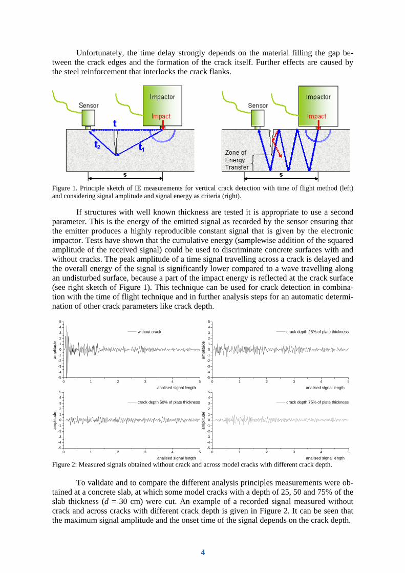
Unfortunately, the time delay strongly depends on the material filling the gap be-tween the crack edges and the formation of the crack itself. Further effects are caused by the steel reinforcement that interlocks the crack flanks.
Figure 1. Principle sketch of IE measurements for vertical crack detection with time of flight method (left) and considering signal amplitude and signal energy as criteria (right).
If structures with well known thickness are tested it is appropriate to use a second parameter. This is the energy of the emitted signal as recorded by the sensor ensuring that the emitter produces a highly reproducible constant signal that is given by the electronic impactor. Tests have shown that the cumulative energy (samplewise addition of the squared amplitude of the received signal) could be used to discriminate concrete surfaces with and without cracks. The peak amplitude of a time signal travelling across a crack is delayed and the overall energy of the signal is significantly lower compared to a wave travelling along an undisturbed surface, because a part of the impact energy is reflected at the crack surface (see right sketch of Figure 1). This technique can be used for crack detection in combina-tion with the time of flight technique and in further analysis steps for an automatic determi-nation of other crack parameters like crack depth.
0 1 2 3 4 5-5-4-3-2-1012345
ampl
itude
analised signal length
without crack
0 1 2 3 4 5-5-4-3-2-1012345
ampl
itude
analised signal length
crack depth 25% of plate thickness
0 1 2 3 4 5-5-4-3-2-1012345
ampl
itude
analised signal length
crack depth 50% of plate thickness
0 1 2 3 4 5-5-4-3-2-1012345
ampl
itude
analised signal length
crack depth 75% of plate thickness
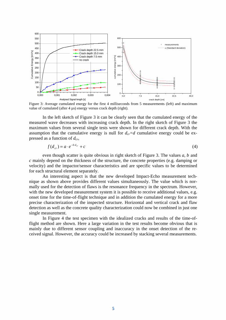
Figure 2: Measured signals obtained without crack and across model cracks with different crack depth.
To validate and to compare the different analysis principles measurements were ob-tained at a concrete slab, at which some model cracks with a depth of 25, 50 and 75% of the slab thickness (d = 30 cm) were cut. An example of a recorded signal measured without crack and across cracks with different crack depth is given in Figure 2. It can be seen that the maximum signal amplitude and the onset time of the signal depends on the crack depth.
4
0,000 0,001 0,002 0,003 0,0040
50
100
150
200
250
300
350
400
450
500
550
600
Crack depth 22.5 mm Crack depth 15.0 mm Crack depth 7.5 mm no crack
Cum
ulat
ive
Ener
gy [m
V²s]
Analysed Signal length [s]0,0 7,5 15,0 22,5 30,0
0
100
200
300
400
500
600
cum
ulat
ive
ener
gy [m
V²s
]
crack depth [cm]
measurements σ (Standard deviation)
Figure 3: Average cumulated energy for the first 4 milliseconds from 5 measurements (left) and maximum value of cumulated (after 4 µs) energy versus crack depth (right).
In the left sketch of Figure 3 it can be clearly seen that the cumulated energy of the measured wave decreases with increasing crack depth. In the right sketch of Figure 3 the maximum values from several single tests were shown for different crack depth. With the assumption that the cumulative energy is null for dcr=d cumulative energy could be ex-pressed as a function of dcr,
ceadf crdbcr +⋅= ⋅−)( (4)
even though scatter is quite obvious in right sketch of Figure 3. The values a, b and c mainly depend on the thickness of the structure, the concrete properties (e.g. damping or velocity) and the impactor/sensor characteristics and are specific values to be determined for each structural element separately.
An interesting aspect is that the new developed Impact-Echo measurement tech-nique as shown above provides different values simultaneously. The value which is nor-mally used for the detection of flaws is the resonance frequency in the spectrum. However, with the new developed measurement system it is possible to receive additional values, e.g. onset time for the time-of-flight technique and in addition the cumulated energy for a more precise characterization of the inspected structure. Horizontal and vertical crack and flaw detection as well as the concrete quality characterization could now be combined in just one single measurement.
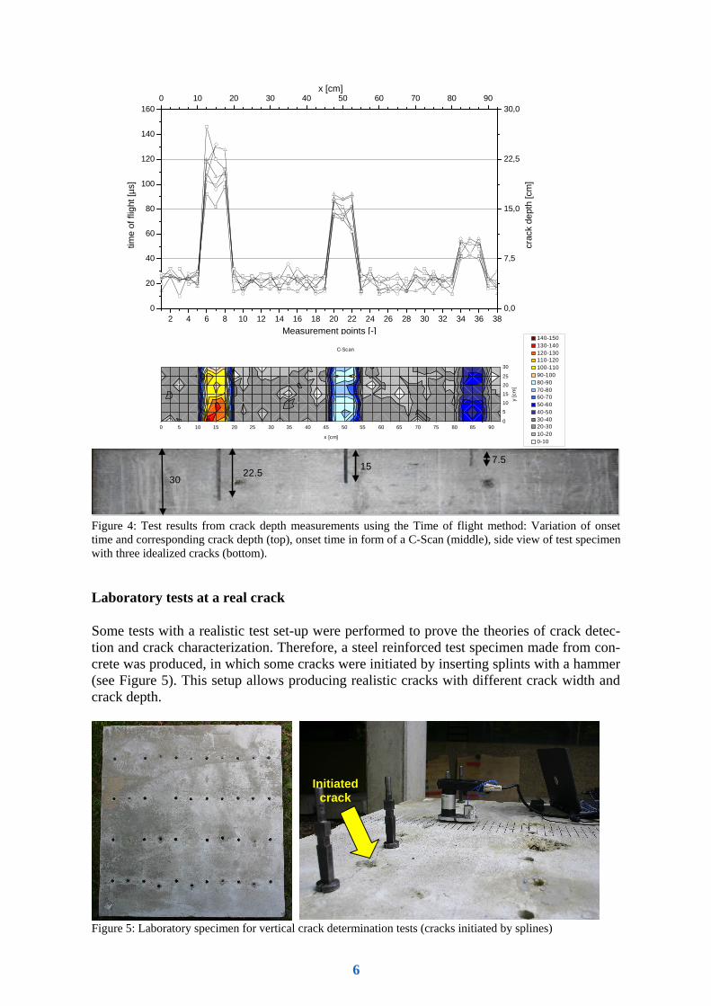
In Figure 4 the test specimen with the idealized cracks and results of the time-of-flight method are shown. Here a large variation in the test results become obvious that is mainly due to different sensor coupling and inaccuracy in the onset detection of the re-ceived signal. However, the accuracy could be increased by stacking several measurements.
5
2 4 6 8 10 12 14 16 18 20 22 24 26 28 30 32 34 36 38
0
20
40
60
80
100
120
140
160
0,0
7,5
15,0
22,5
30,00 10 20 30 40 50 60 70 80 90
time
of fl
ight
[µs]
Measurement points [-]
crac
k de
pth
[cm
]
x [cm]
0 5 10 15 20 25 30 35 40 45 50 55 60 65 70 75 80 85 90
0
5
10
15
20
25
30
x [cm]
y [c
m]
C-Scan
140-150130-140120-130110-120100-11090-10080-9070-8060-7050-6040-5030-4020-3010-200-10
7.5 15
22.5 30
Figure 4: Test results from crack depth measurements using the Time of flight method: Variation of onset time and corresponding crack depth (top), onset time in form of a C-Scan (middle), side view of test specimen with three idealized cracks (bottom).
Laboratory tests at a real crack
Some tests with a realistic test set-up were performed to prove the theories of crack detec-tion and crack characterization. Therefore, a steel reinforced test specimen made from con-crete was produced, in which some cracks were initiated by inserting splints with a hammer (see Figure 5). This setup allows producing realistic cracks with different crack width and crack depth.
Figure 5: Laboratory specimen for vertical crack determination tests (cracks initiated by splines)
Initiated crack
6
measurement grid
sensor/impactor distance
initiated crack
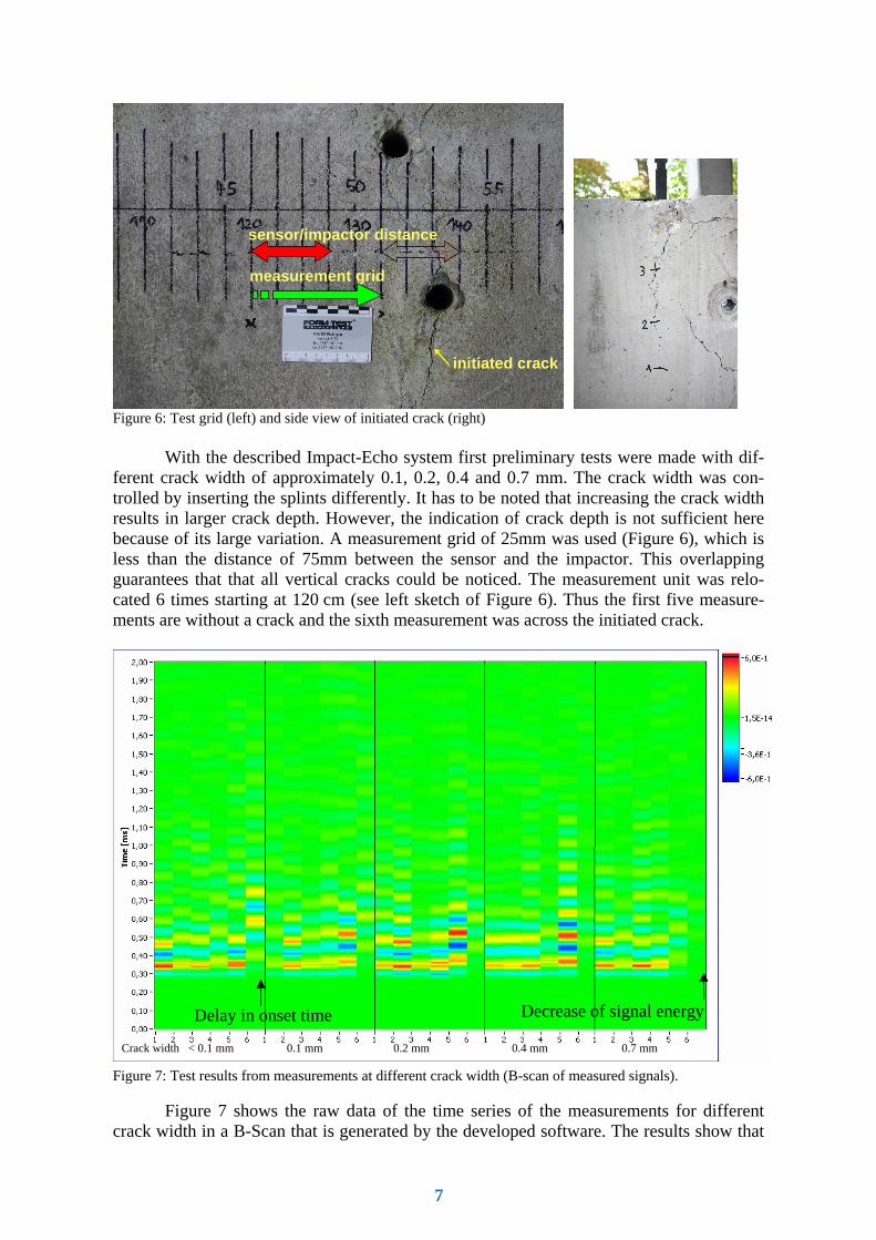
Figure 6: Test grid (left) and side view of initiated crack (right)
With the described Impact-Echo system first preliminary tests were made with dif-ferent crack width of approximately 0.1, 0.2, 0.4 and 0.7 mm. The crack width was con-trolled by inserting the splints differently. It has to be noted that increasing the crack width results in larger crack depth. However, the indication of crack depth is not sufficient here because of its large variation. A measurement grid of 25mm was used (Figure 6), which is less than the distance of 75mm between the sensor and the impactor. This overlapping guarantees that that all vertical cracks could be noticed. The measurement unit was relo-cated 6 times starting at 120 cm (see left sketch of Figure 6). Thus the first five measure-ments are without a crack and the sixth measurement was across the initiated crack.
Figure 7: Test results from measurements at different crack width (B-scan of measured signals).
Figure 7 shows the raw data of the time series of the measurements for different crack width in a B-Scan that is generated by the developed software. The results show that
Crack width < 0.1 mm 0.1 mm 0.2 mm 0.4 mm 0.7 mm
Delay in onset time Decrease of signal energy
7
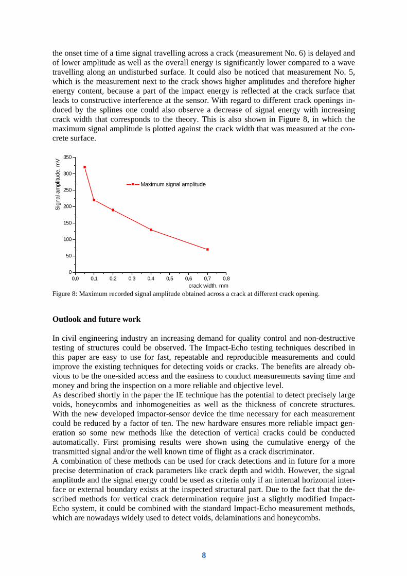
the onset time of a time signal travelling across a crack (measurement No. 6) is delayed and of lower amplitude as well as the overall energy is significantly lower compared to a wave travelling along an undisturbed surface. It could also be noticed that measurement No. 5, which is the measurement next to the crack shows higher amplitudes and therefore higher energy content, because a part of the impact energy is reflected at the crack surface that leads to constructive interference at the sensor. With regard to different crack openings in-duced by the splines one could also observe a decrease of signal energy with increasing crack width that corresponds to the theory. This is also shown in Figure 8, in which the maximum signal amplitude is plotted against the crack width that was measured at the con-crete surface.
0,0 0,1 0,2 0,3 0,4 0,5 0,6 0,7 0,80
50
100
150
200
250
300
350
Sign
al a
mpl
itude
, mV
crack width, mm
Maximum signal amplitude
Figure 8: Maximum recorded signal amplitude obtained across a crack at different crack opening.
Outlook and future work
In civil engineering industry an increasing demand for quality control and non-destructive testing of structures could be observed. The Impact-Echo testing techniques described in this paper are easy to use for fast, repeatable and reproducible measurements and could improve the existing techniques for detecting voids or cracks. The benefits are already ob-vious to be the one-sided access and the easiness to conduct measurements saving time and money and bring the inspection on a more reliable and objective level. As described shortly in the paper the IE technique has the potential to detect precisely large voids, honeycombs and inhomogeneities as well as the thickness of concrete structures. With the new developed impactor-sensor device the time necessary for each measurement could be reduced by a factor of ten. The new hardware ensures more reliable impact gen-eration so some new methods like the detection of vertical cracks could be conducted automatically. First promising results were shown using the cumulative energy of the transmitted signal and/or the well known time of flight as a crack discriminator. A combination of these methods can be used for crack detections and in future for a more precise determination of crack parameters like crack depth and width. However, the signal amplitude and the signal energy could be used as criteria only if an internal horizontal inter-face or external boundary exists at the inspected structural part. Due to the fact that the de-scribed methods for vertical crack determination require just a slightly modified Impact-Echo system, it could be combined with the standard Impact-Echo measurement methods, which are nowadays widely used to detect voids, delaminations and honeycombs.
8
These newly developed methods including a new software front end will be evaluated and calibrated during further tests. The tests will give more details about the reproducibility and reliability of this method. This will help to further optimize the hardware that is still in form of a prototype at this moment. After that the next actions are the development, evaluation and implementation of proper algorithms for semiautomatic or automatic crack detection.
Acknowledegement
The work and developments presented in this paper were the supported by the European Community in the frame of the Integrated Project “Sustainable Bridges”.
References
[1] Carino, N.J., Sansalone, M., and Hsu, N.N. 1986. A Point Source - Point Receiver Technique for Flaw Detection in Concrete", Journal of the American Concrete Institute, Vol. 83, No. 2, pp. 199-208.
[2] Sansalone, M. J.; Streett, W. B. 1997. Impact-Echo. Bullbrier Press, Ithaca, 336 pp. [3] RI-ZFP-TU 2001. Richtlinie für die Anwendung der zerstörungsfreien Prüfung von
Tunnelinnenschalen, Bundesanstalt für Straßenwesen, Reg.-Nr. 05.72, Verkehrsblatt-Dok. Nr. S 1050 - Vers. 03/01.
[4] Colla, C., Schneider, G., Wöstmann, J., Wiggenhauser, H. 1999. Automated Impact-Echo: 2- and 3-D imaging of concrete elements. NDT.net, Vol. 4, No. 5.
[5] Weiler, B. 1995. State assessment of sandstone by ultrasonic measurements. Otto-Graf-Journal, Vol. 6, pp. 188-199.
[6] Grosse, C. U., Weiler, B. 1997. Analyse von Vielfachreflexionen nach mechanischer Pulsanregung - Impakt-Echo-Verfahren (FMPA). In: "Erprobung und Bewertung zerstörungsfreier Prüfverfahren für Betonbrücken", Abschlussbericht FE-Nr.:9.94241 F1 der Bundesanstalt für Materialprüfung BAM, H. B18, Berlin, pp. 116-123.
[7] Kretschmar, F., Köhler, B., Hentges, G. 1997. Analyse von Vielfachreflexionen nach mechanischer Pulsanregung - Impakt-Echo-Verfahren (EADQ). In: "Erprobung und Bewertung zerstörungsfreier Prüfverfahren für Betonbrücken", Abschlussbericht FE-Nr.:9.94241 F1 der Bundesanstalt für Material-prüfung BAM, H. B18, Berlin, pp. 104-115.
[8] Lausch, R., Wiggenhauser, H., Schubert, F. 2002. Geometrieeffekte und Hüllrohrortung bei der Impaktecho-Prüfung von Betonbauteilen – Experimentelle und modelltheoretische Ergebnisse. Proc. DGZfP Annual meeting, Weimar, BB80-CD, NDT.net, Vol. 7, No. 11.
[9] Motz, M., Krüger, M., Grosse, C. U., Haller, P., Beutel, R. 2003. Impact-Echo: New Developments Regarding Hardware and Software. Intern. Symp. Non-Destructive Testing in Civil Engineering (NDT-CE), Proceedings BB 85-CD, Berlin.
[10] Grosse, C. U., Reinhardt, H. W., Beutel, R. 2004. Impact-Echo Measurement on Fresh and Hardening Concrete. In: Concrete Science and Engineering (Ed. K. Kovler, et al.), RILEM PRO 36, RILEM Publ. S.A.R.L., pp 95-104.
[11] Grosse, C. U 1996.. Quantitative zerstörungsfreie Prüfung von Baustoffen mittels Schallemis-sionsanalyse und Ultraschall. Ph.D. thesis, University of Stuttgart, 168 pp.
[12] Sansalone, M. J., Lin, J.-M., Streett, W. B. 1998. Determining the depth of surface-opening cracks using impact-generated stress waves and time-of-flight techniques. ACI Mat. J. Vol. 95, pp. 168-177.
9


![A Soft Computing Approach to Crack Detection and Impact … · 2014. 4. 22. · the crack detection [1, 2]. The crack detection is done by measuring lamb wave signals using the dual](https://static.fdocuments.in/doc/165x107/60ec9be3b41124749d1a1a68/a-soft-computing-approach-to-crack-detection-and-impact-2014-4-22-the-crack.jpg)