Smart-UPS UPS Operation Manual - ExcessUPS UPS Operation Manual Operation ...
P/N 016-0171-664 Rev. A 10/17 E29486
Copyright 2017
CR7 Operation Manual
While every effort has been made to ensure the accuracy of this document, Raven Industries assumes no responsibility for omissions and errors. Nor is any liability assumed for damages resulting from the use of information contained herein.
Raven Industries shall not be responsible or liable for incidental or consequential damages or a loss of anticipated benefits or profits, work stoppage or loss, or impairment of data arising out of the use, or inability to use, this system or any of its components. Raven Industries shall not be held responsible for any modifications or repairs made outside our facilities, nor damages resulting from inadequate maintenance of this system.
As with all wireless and satellite signals, several factors may affect the availability and accuracy of wireless and satellite navigation and correction services (e.g. GPS, GNSS, SBAS, etc.). Therefore, Raven Industries cannot guarantee the accuracy, integrity, continuity, or availability of these services and cannot guarantee the ability to use Raven systems, or products used as components of systems, which rely upon the reception of these signals or availability of these services. Raven Industries accepts no responsibility for the use of any of these signals or services for other than the stated purpose.
Disclaimer

CONTENTSContents . . . . . . . . . . . . . . . . . . . . . . . . . . . . . . . . . . . . . . . . . . . . . . . . . . . . . . 1Description . . . . . . . . . . . . . . . . . . . . . . . . . . . . . . . . . . . . . . . . . . . . . . . . . . . . 3Overview . . . . . . . . . . . . . . . . . . . . . . . . . . . . . . . . . . . . . . . . . . . . . . . . . . . . . . 3
Care and Maintenance . . . . . . . . . . . . . . . . . . . . . . . . . . . . . . . . . . . . . . . . . . 4Installation . . . . . . . . . . . . . . . . . . . . . . . . . . . . . . . . . . . . . . . . . . . . . . . . . . . . . 5
Quick Start Settings . . . . . . . . . . . . . . . . . . . . . . . . . . . . . . . . . . . . . . . . . . . . . 6Home Screen Overview . . . . . . . . . . . . . . . . . . . . . . . . . . . . . . . . . . . . . . . . . . 8CR7 Settings Screen Overview . . . . . . . . . . . . . . . . . . . . . . . . . . . . . . . . . . . . 9
Machine Configuration. . . . . . . . . . . . . . . . . . . . . . . . . . . . . . . . . . . . . . . . . . 12Deleting An Existing Machine . . . . . . . . . . . . . . . . . . . . . . . . . . . . . . . . . . . . 14Creating A Mounted Implement . . . . . . . . . . . . . . . . . . . . . . . . . . . . . . . . . . . 14Adding Drawn Equipment . . . . . . . . . . . . . . . . . . . . . . . . . . . . . . . . . . . . . . . 15ISO Boom Configuration . . . . . . . . . . . . . . . . . . . . . . . . . . . . . . . . . . . . . . . . 16SCS Configuration . . . . . . . . . . . . . . . . . . . . . . . . . . . . . . . . . . . . . . . . . . . . . 16
Creating a New Grower, Farm, and Field . . . . . . . . . . . . . . . . . . . . . . . . . . . 16Accessing, Editing, and Deleting Existing Growers, Farms, and Fields . . . . 17Delete existing Grower, Farm, or Field . . . . . . . . . . . . . . . . . . . . . . . . . . . . . 18
Starting a Job . . . . . . . . . . . . . . . . . . . . . . . . . . . . . . . . . . . . . . . . . . . . . . . . . 18Starting an existing job . . . . . . . . . . . . . . . . . . . . . . . . . . . . . . . . . . . . . . . . . 18Start a New job in a New field . . . . . . . . . . . . . . . . . . . . . . . . . . . . . . . . . . . . 20
Run Screen Overview . . . . . . . . . . . . . . . . . . . . . . . . . . . . . . . . . . . . . . . . . . . 21Run Screen Overview . . . . . . . . . . . . . . . . . . . . . . . . . . . . . . . . . . . . . . . . . . 21Widgets . . . . . . . . . . . . . . . . . . . . . . . . . . . . . . . . . . . . . . . . . . . . . . . . . . . . . 22
Scouting Objects . . . . . . . . . . . . . . . . . . . . . . . . . . . . . . . . . . . . . . . . . . . . . . 24Creating a Flag . . . . . . . . . . . . . . . . . . . . . . . . . . . . . . . . . . . . . . . . . . . . . . . 24Creating a Field Boundary, Do Not apply Zone, Application Zone, or Line . . 25
Adjusting Section Control . . . . . . . . . . . . . . . . . . . . . . . . . . . . . . . . . . . . . . . 25Adjusting Rate Control Settings . . . . . . . . . . . . . . . . . . . . . . . . . . . . . . . . . . 26Adjusting Settings . . . . . . . . . . . . . . . . . . . . . . . . . . . . . . . . . . . . . . . . . . . . . 27
Display Settings . . . . . . . . . . . . . . . . . . . . . . . . . . . . . . . . . . . . . . . . . . . . . . . 27Localization . . . . . . . . . . . . . . . . . . . . . . . . . . . . . . . . . . . . . . . . . . . . . . . . . . 27Serial Port Information . . . . . . . . . . . . . . . . . . . . . . . . . . . . . . . . . . . . . . . . . . 28GPS . . . . . . . . . . . . . . . . . . . . . . . . . . . . . . . . . . . . . . . . . . . . . . . . . . . . . . . . 28Remote Support. . . . . . . . . . . . . . . . . . . . . . . . . . . . . . . . . . . . . . . . . . . . . . . 29Master Switch Configuration . . . . . . . . . . . . . . . . . . . . . . . . . . . . . . . . . . . . . 30Universal Terminal (UT) Settings. . . . . . . . . . . . . . . . . . . . . . . . . . . . . . . . . . 30Lightbar Configuration . . . . . . . . . . . . . . . . . . . . . . . . . . . . . . . . . . . . . . . . . . 30Notifications . . . . . . . . . . . . . . . . . . . . . . . . . . . . . . . . . . . . . . . . . . . . . . . . . . 31
File Manager . . . . . . . . . . . . . . . . . . . . . . . . . . . . . . . . . . . . . . . . . . . . . . . . . . 31File Types . . . . . . . . . . . . . . . . . . . . . . . . . . . . . . . . . . . . . . . . . . . . . . . . . . . 31Copy a File. . . . . . . . . . . . . . . . . . . . . . . . . . . . . . . . . . . . . . . . . . . . . . . . . . . 32Delete a File. . . . . . . . . . . . . . . . . . . . . . . . . . . . . . . . . . . . . . . . . . . . . . . . . . 32Importing Maps, Guidance Lines, and Feature Unlocks . . . . . . . . . . . . . . . . 33Loading and RUNNING A Prescription Map . . . . . . . . . . . . . . . . . . . . . . . . . 34
1

Ejecting the USB . . . . . . . . . . . . . . . . . . . . . . . . . . . . . . . . . . . . . . . . . . . . . . 37Software Update . . . . . . . . . . . . . . . . . . . . . . . . . . . . . . . . . . . . . . . . . . . . . . . 37
Downloading a CR7 Update to USB . . . . . . . . . . . . . . . . . . . . . . . . . . . . . . . 38Installing CR7 Updates via USB . . . . . . . . . . . . . . . . . . . . . . . . . . . . . . . . . . 39SmarTrax System Information . . . . . . . . . . . . . . . . . . . . . . . . . . . . . . . . . . . . 39
Feature Unlocks . . . . . . . . . . . . . . . . . . . . . . . . . . . . . . . . . . . . . . . . . . . . . . . 39Temporary Unlock activation . . . . . . . . . . . . . . . . . . . . . . . . . . . . . . . . . . . . . 39Entering a Permanent Unlock . . . . . . . . . . . . . . . . . . . . . . . . . . . . . . . . . . . . 41
System Shutdown. . . . . . . . . . . . . . . . . . . . . . . . . . . . . . . . . . . . . . . . . . . . . . 41
2
DESCRIPTION
The latest innovation from Raven is a small, yet powerful, field computer. The CR7™ is a 7” lightweight field computer with a simplified widget concept. Customizable in-job layouts, easily accessible settings, and ISO UT and Task Controller capabilities make this mighty unit a plug-and-play option for building an affordable system. The CR7 is compatible with many Raven products including:
• SmarTrax™ or SmarTrax MD™ automated steering control.• Slingshot Online Services.• Raven ISO Products such as Hawkeye® and Raven Rate Control Module (RCM).• Raven AutoBoom™ boom height management.• Raven AccuBoom™.• Raven SCS 400, 600, 4400, and 4600 series consoles.
NOTE: Contact a local Raven dealer for information on additional features and options available for use with the CR7.
OVERVIEW
This section provides a basic overview of the front and back of the CR7. References to various parts of the CR7 may be mentioned through this manual. It is important to become familiar with the CR7 prior to operation.
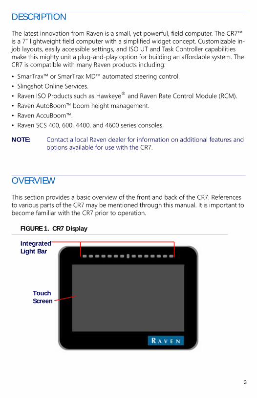
FIGURE 1. CR7 Display
Touch Screen
Integrated Light Bar
3
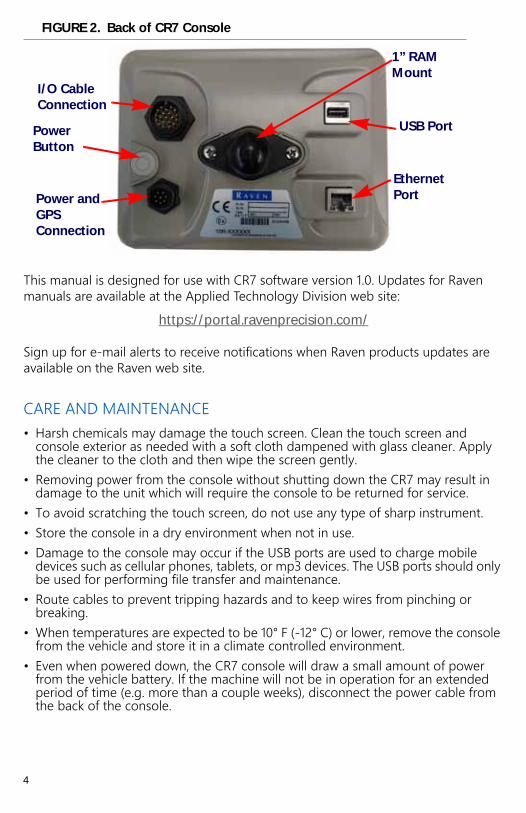
FIGURE 2. Back of CR7 Console
This manual is designed for use with CR7 software version 1.0. Updates for Raven manuals are available at the Applied Technology Division web site:
https://portal.ravenprecision.com/
Sign up for e-mail alerts to receive notifications when Raven products updates are available on the Raven web site.
CARE AND MAINTENANCE• Harsh chemicals may damage the touch screen. Clean the touch screen and
console exterior as needed with a soft cloth dampened with glass cleaner. Apply the cleaner to the cloth and then wipe the screen gently.
• Removing power from the console without shutting down the CR7 may result in damage to the unit which will require the console to be returned for service.
• To avoid scratching the touch screen, do not use any type of sharp instrument.• Store the console in a dry environment when not in use.• Damage to the console may occur if the USB ports are used to charge mobile
devices such as cellular phones, tablets, or mp3 devices. The USB ports should only be used for performing file transfer and maintenance.
• Route cables to prevent tripping hazards and to keep wires from pinching or breaking.
• When temperatures are expected to be 10° F (-12° C) or lower, remove the console from the vehicle and store it in a climate controlled environment.
• Even when powered down, the CR7 console will draw a small amount of power from the vehicle battery. If the machine will not be in operation for an extended period of time (e.g. more than a couple weeks), disconnect the power cable from the back of the console.
Ethernet Port
1” RAM Mount
I/O Cable Connection
Power Button
USB Port
Power and GPS Connection
4
INSTALLATION1. Mount the antenna on the centerline of the tallest point of the vehicle (usually on
the top of the vehicle cabin) using the magnetic mount. Make sure that the antenna has a clear, 360° view of the sky. If the mounting location is not metallic, use a mounting plate to mount the antenna.
2. Route the Power/GPS cable to the back of the CR7 console and connect it to the Power/GPS port.
3. Use the provided 1” RAM mount arm to install the CR7 inside the cab.4. For additional cabling and connection assistance, refer to the CR7 Installation
Quick Guide. Additional system diagrams are available on the Raven web site.
https://portal.ravenprecision.com/
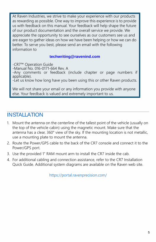
At Raven Industries, we strive to make your experience with our products as rewarding as possible. One way to improve this experience is to provide us with feedback on this manual. Your feedback will help shape the future of our product documentation and the overall service we provide. We appreciate the opportunity to see ourselves as our customers see us and are eager to gather ideas on how we have been helping or how we can do better. To serve you best, please send an email with the following information to
-CR7™ Operation Guide-Manual No. 016-0171-664 Rev. A-Any comments or feedback (include chapter or page numbers ifapplicable).-Let us know how long have you been using this or other Raven products.
We will not share your email or any information you provide with anyone else. Your feedback is valued and extremely important to us.
5
QUICK START SETTINGS
When starting the CR7 for the first time a setup wizard will walk you through a setup process and, if desired, allow you to quickly start creating guidance lines. This section covers the first time startup.
IMPORTANT: Entering all measurements as accurately as possible will ensure fewer issues with field operations. Verify all measurements before entering them into the CR7 and ensure you enter the numbers correctly.
After powering up the CR7 for the first time:
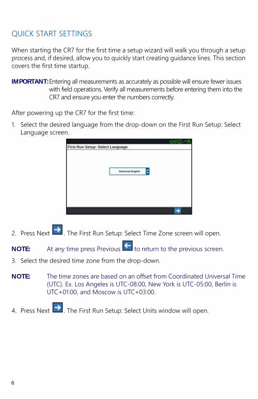
1. Select the desired language from the drop-down on the First Run Setup: Select Language screen.
2. Press Next . The First Run Setup: Select Time Zone screen will open.
NOTE: At any time press Previous to return to the previous screen.
3. Select the desired time zone from the drop-down.
NOTE: The time zones are based on an offset from Coordinated Universal Time (UTC). Ex. Los Angeles is UTC-08:00, New York is UTC-05:00, Berlin is UTC+01:00, and Moscow is UTC+03:00.
4. Press Next . The First Run Setup: Select Units window will open.
6
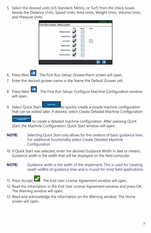
5. Select the desired units (US Standard, Metric, or Turf) from the check boxes beside the Distance Units, Speed Units, Area Units, Weight Units, Volume Units, and Pressure Units.
6. Press Next . The First Run Setup: Grower/Farm screen will open.7. Enter the desired grower name in the Name the Default Grower cell.
8. Press Next . The First Run Setup: Configure Machine Configuration window will open.
9. Select Quick Start to quickly create a simple machine configuration that can be edited later. If desired, select Create Detailed Machine Configuration
to create a detailed machine configuration. After pressing Quick Start, the Machine Configuration: Quick Start window will open.
NOTE: Selecting Quick Start only allows for the creation of basic guidance lines. For additional functionality select Create Detailed Machine Configuration.
10. If Quick Start was selected, enter the desired Guidance Width in feet or meters. Guidance width is the width that will be displayed on the field computer.
NOTE: Guidance width is the width of the implement. This is used for creating swath widths of guidance lines and is crucial for most field applications.
11. Press Accept . The End User License Agreement window will open.12. Read the information in the End User License Agreement window and press OK.
The Warning window will open.13. Read and acknowledge the information on the Warning window. The Home
screen will open.
7
14. Refer to the appropriate sections in this manual to adjust the settings, start a job, and perform other tasks on this screen.
NOTE: Press the Settings button at any time it is visible to return to the Settings screen.
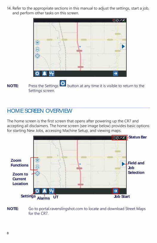
HOME SCREEN OVERVIEW
The home screen is the first screen that opens after powering up the CR7 and accepting all disclaimers. The home screen (see image below) provides basic options for starting New Jobs, accessing Machine Setup, and viewing maps.
NOTE: Go to portal.ravenslingshot.com to locate and download Street Maps for the CR7.
Zoom Functions
Settings Alarms
Field and Job Selection
Status Bar
Job StartUT
Zoom to Current Location
8

CR7 SETTINGS SCREEN OVERVIEW
STATUS BAR
The status bar includes the following informational icons for quick reference. Note that the different icon colors indicate different status:
NOTE: Typically, if the status is green it means that it is active. If it is grayed out, that feature is inactive. Slingshot displays different color combinations depending on activity.
GPS Bad
No GPS Data
GPS Warning
GPS Ideal
GPS Disabled
Remote Support Disabled
Slingshot Disabled
SmarTrax Disabled
Job Load Progress
SmarTrax Node Download
SmarTrax Ready
SmarTrax Not Ready
Scanning USB
Remote Support Active
Software Update
USB Transfer
Slingshot Connected
Slingshot Transfer
Bluetooth Connected
9

SETTINGS ICONS
The table below shows the icons from the settings screen and provides a brief description of their function. Note that the icons may appear over multiple screens. Scroll to the left or right to view the other screens.
Icon Information
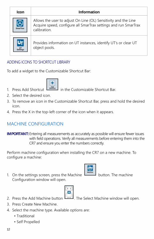
The display can be set to Day or Night Mode and the Screen and Lightbar Brightness can be adjusted.
Allows the user to add other icons to the Shortcut Library on the main settings screen.
Allows users to import/export files as well as view and delete files.
Create, Rename, or Delete Growers, Farms, or Fields.
Review GPS information, diagnostics, and adjust settings.
SmarTrax StatusRemote Support Status Slingshot
StatusGPS Status
Notifications Universal Terminal
Customizable Shortcut Bar
10
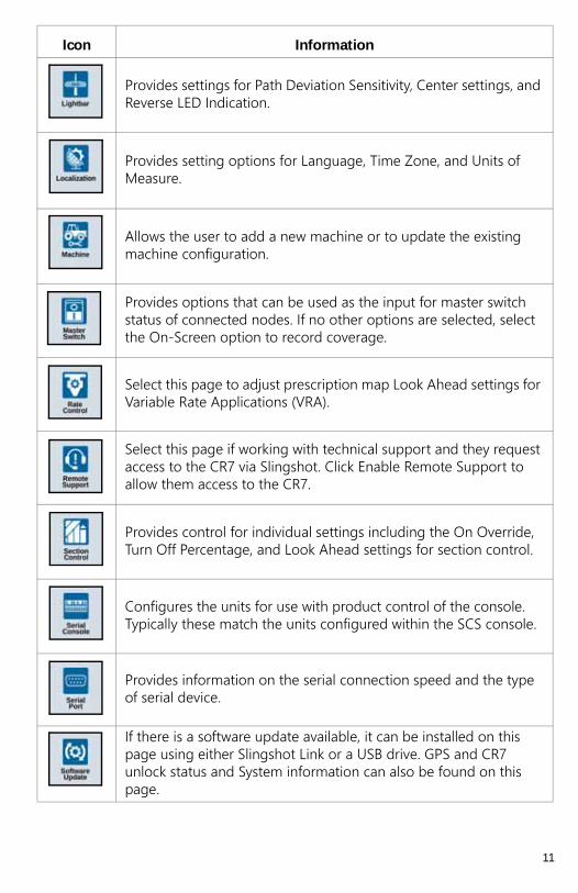
Provides settings for Path Deviation Sensitivity, Center settings, and Reverse LED Indication.
Provides setting options for Language, Time Zone, and Units of Measure.
Allows the user to add a new machine or to update the existing machine configuration.
Provides options that can be used as the input for master switch status of connected nodes. If no other options are selected, select the On-Screen option to record coverage.
Select this page to adjust prescription map Look Ahead settings for Variable Rate Applications (VRA).
Select this page if working with technical support and they request access to the CR7 via Slingshot. Click Enable Remote Support to allow them access to the CR7.
Provides control for individual settings including the On Override, Turn Off Percentage, and Look Ahead settings for section control.
Configures the units for use with product control of the console. Typically these match the units configured within the SCS console.
Provides information on the serial connection speed and the type of serial device.
If there is a software update available, it can be installed on this page using either Slingshot Link or a USB drive. GPS and CR7 unlock status and System information can also be found on this page.
Icon Information
11
ADDING ICONS TO SHORTCUT LIBRARY
To add a widget to the Customizable Shortcut Bar:
1. Press Add Shortcut in the Customizable Shortcut Bar.2. Select the desired icon.3. To remove an icon in the Customizable Shortcut Bar, press and hold the desired
icon.4. Press the X in the top-left corner of the icon when it appears.
MACHINE CONFIGURATION
IMPORTANT: Entering all measurements as accurately as possible will ensure fewer issues with field operations. Verify all measurements before entering them into the CR7 and ensure you enter the numbers correctly.
Perform machine configuration when installing the CR7 on a new machine. To configure a machine:
1. On the settings screen, press the Machine button. The machine Configuration window will open.
2. Press the Add Machine button . The Select Machine window will open.3. Press Create New Machine.4. Select the machine type. Available options are:
• Traditional• Self Propelled
Allows the user to adjust On Line (OL) Sensitivity and the Line Acquire speed, configure all SmarTrax settings and run SmarTrax calibration.
Provides information on UT instances, identify UT’s or clear UT object pools.
Icon Information
12
• Articulated• Tracked
5. Enter the machine name in the <enter name> field.
6. Press Next . The Antenna Height Above Ground window will open.7. Enter the Height from the ground to the center of the antenna.
8. Press Next . The Distance: Antenna Offset From Center will open.9. Enter the distance the antenna is offset from the center of the implement.10. Select if the offset distance is to the Left or Right of center.
11. Press Next . The Distance: Rear Axle to Antenna window will open.12. Enter the distance from the center of the rear axle to the center of the antenna.13. Select if the distance is Ahead of or Behind the axle.
NOTE: If an Articulated machine, select if the antenna is in front of or behind the articulation point.
If a Tracked machine, select if the antenna is in front of or behind the track center.
14. Press Next. For Articulated Tractors, enter The Distance:Rear Axle to Pivot.
NOTE: This allows the CR7 to calculate the correct position of the implement for determining the coverage rate and boom control functions.
15. Enter the distance from the pivot point to the center of the rear axle.
16. Press Next . The Distance: Hitch Offset From Center window will open.17. Enter the distance from the center of the machine to the center of the hitch.
NOTE: This allows the CR7 to calculate the correct position of the implement for determining the coverage rate and boom control functions.
18. Select if the distance is to the Left or Right of the axle.
19. Press Next . The Distance: Rear Axle to Hitch window will open.20.Enter the Distance from the rear axle to the hitch.
NOTE: If a Tracked Machine, enter the Distance from the track center to the hitch.
21. Press Accept .
13

DELETING AN EXISTING MACHINE
To delete an existing machine:
1. Press Machine on the CR7 settings screen.2. Select the desired machine.
3. Press Delete . The Confirm Delete Machine window will open.
4. Select Accept to delete the machine or cancel to return to the Select Machine window.
CREATING A MOUNTED IMPLEMENT
To create a new implement that is mounted to the frame structure or the machine:
1. On the settings page, press the Machine button. The Machine Configuration window will open.
2. Press the Edit icon. Either modify the existing machine or select an implement to mount to an existing machine.
3. Add Machine button . The Select Machine window will open.4. Verify a machine is selected from the drop down.5. Press Mount Equipment.6. Press Create New Equipment.7. Enter a name for the equipment.
NOTE: If selecting a SCS or an item connected to the ISObus, skip to step 15.
8. Enter the Total Width.9. Enter the Number of Sections.
10. Press Next . The Guidance Width will open. The Guidance Width is automatically assigned the same value as the Total Width.
11. If desired, enter a different Guidance Width.
12. Press Next . The Section Layout window will open.
14

13. Review the information on the Section Layout information. If desired, select the width below one of the sections to adjust the width for that section.
14. Press Next . The Axle to Equipment window will open.15. Enter the Distance from the axle to the equipment.16. Select if the equipment is Ahead or Behind the axle.
17. Press Next . The Equipment Offset From Center window will open.18. Enter the Distance from the center of the implement to the center of the machine.19. Select if the equipment is offset to the Left or Right of center.
20.Press Accept if all of the settings are correct. If needed, press previous and adjust information.
ADDING DRAWN EQUIPMENT
This section describes how to add a piece of drawn equipment to an existing machine:
NOTE: Drawn equipment included two wheel and four wheel carts. Unless the equipment is steered from the front wheels choose a two wheel cart.
1. On the settings page, press the Machine button. The machine Configuration window will open.
2. Press Add Drawn Equipment . The Select Cart window will open.3. Select the desired cart type from the <Select Cart> drop-down or select Create
New Cart.4. After selecting Create New Cart the Create New Cart screen will open. If creating
a new cart continue with the process. If selecting an existing cart, skip to step 11.5. Enter the desired name. 6. Select if the cart is a Two Wheel Cart or Four Wheel Cart.
7. Press Next . The Distance: Tongue to Axle will open.8. Enter the distance from the center of axle to the front of the tongue.
9. Press Next . If a Four Wheel Cart the Distance: Axle to Axle window will open. Enter the distance between the two axles. If a Two Wheel Cart it the Distance: Axle to Hitch screen will open.
15
10. Enter the distance from the center to the rear axle to the back hitch.
11. Press Accept . 12. Press Mount Equipment. The drawn equipment is now mounted to the
implement.
13. To edit a piece of Drawn Equipment, press the Edit button.14. To unmount a piece of Drawn Equipment, reset the configuration then add select
the desired tractor again.
NOTE: Resetting an implement or piece of equipment will not delete previously created profiles but will place it back in the inventory.
ISO BOOM CONFIGURATION
During machine configuration, if creating a self-propelled machine with an ISO boom connected to the CANBUS, select the ISO Boom instead of creating a new boom.
SCS CONFIGURATION
During machine configuration, if selecting a SCS, select the desired SCS instead of creating a new boom (IS THIS RIGHT).
CREATING A NEW GROWER, FARM, AND FIELD
Grower, Field, and Farm (GFF) data can be added to the CR7 prior to starting a new job. It is also possible to import GFF data from a Viper 4.
1. On the Settings screen, press GFF . The Grower Farm Field Information window will open.
2. Select New from the Grower column. The Add Grower window will open.3. Press in the Enter Grower Name cell and enter the desired grower name.
16
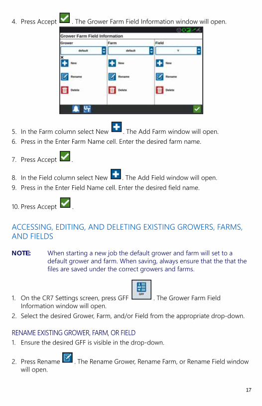
4. Press Accept . The Grower Farm Field Information window will open.
5. In the Farm column select New . The Add Farm window will open.6. Press in the Enter Farm Name cell. Enter the desired farm name.
7. Press Accept .
8. In the Field column select New . The Add Field window will open.9. Press in the Enter Field Name cell. Enter the desired field name.
10. Press Accept .
ACCESSING, EDITING, AND DELETING EXISTING GROWERS, FARMS, AND FIELDS
NOTE: When starting a new job the default grower and farm will set to a default grower and farm. When saving, always ensure that the that the files are saved under the correct growers and farms.
1. On the CR7 Settings screen, press GFF . The Grower Farm Field Information window will open.
2. Select the desired Grower, Farm, and/or Field from the appropriate drop-down.
RENAME EXISTING GROWER, FARM, OR FIELD1. Ensure the desired GFF is visible in the drop-down.
2. Press Rename . The Rename Grower, Rename Farm, or Rename Field window will open.
17
3. Enter the new name.
4. Press Accept .
DELETE EXISTING GROWER, FARM, OR FIELD1. Ensure the desired GFF is visible in the drop-down.
2. Select Delete .
NOTE: If deleting a Farm with associated Fields, delete the Fields before attempting to delete the Farm.
NOTE: If deleting a Field with associated files ( jobs, scouted objects, guidance lines), delete the files before attempting to delete the Field.
STARTING A JOB
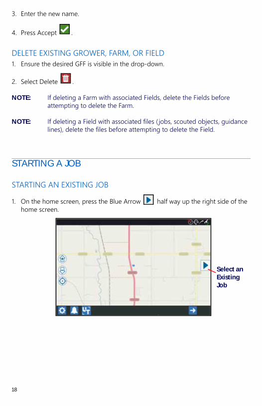
STARTING AN EXISTING JOB
1. On the home screen, press the Blue Arrow half way up the right side of the home screen.
Select an Existing Job
18

2. Select the desired field from the Select Field list.
1. Select the desired job or select New Job to start a new job.
Select Existing Field
Existing Job
New Job
19

START A NEW JOB IN A NEW FIELD
2. On the home screen press Next at the bottom of the screen or press the
Blue Arrow and select New Job.
3. Enter a field name in the Give This Field A Name cell. 4. Enter a job name in the Give Your Job a Name cell.
5. Press Next . The Product To Implement Assignment window will open.
6. Review the coverage to implement assignments. If desired, press Edit . The edit window will open.
7. Select the desired coverage option(s) from the drop-down menu.
8. Press Accept .
9. Press Next . The run screen will open.
Start New Job
20
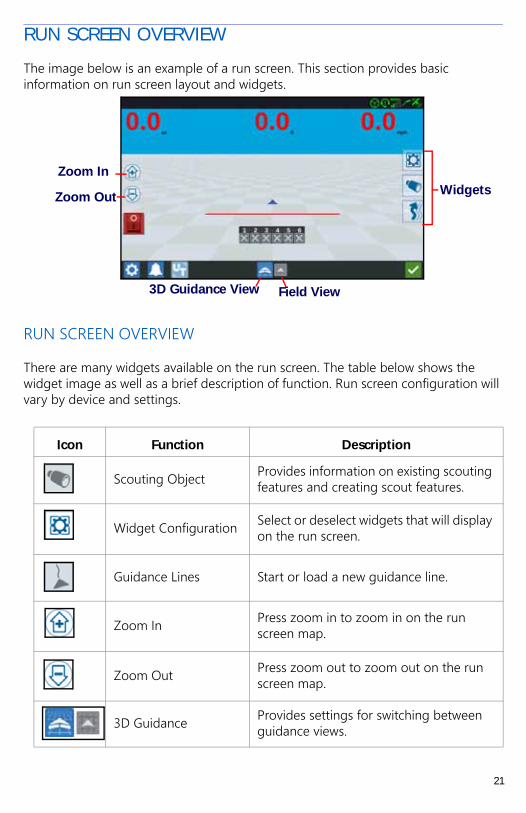
RUN SCREEN OVERVIEW
The image below is an example of a run screen. This section provides basic information on run screen layout and widgets.
RUN SCREEN OVERVIEW
There are many widgets available on the run screen. The table below shows the widget image as well as a brief description of function. Run screen configuration will vary by device and settings.
Icon Function Description
Scouting Object Provides information on existing scouting features and creating scout features.
Widget Configuration Select or deselect widgets that will display on the run screen.
Guidance Lines Start or load a new guidance line.
Zoom In Press zoom in to zoom in on the run screen map.
Zoom Out Press zoom out to zoom out on the run screen map.
3D Guidance Provides settings for switching between guidance views.
WidgetsZoom In
Zoom Out
3D Guidance View Field View
21
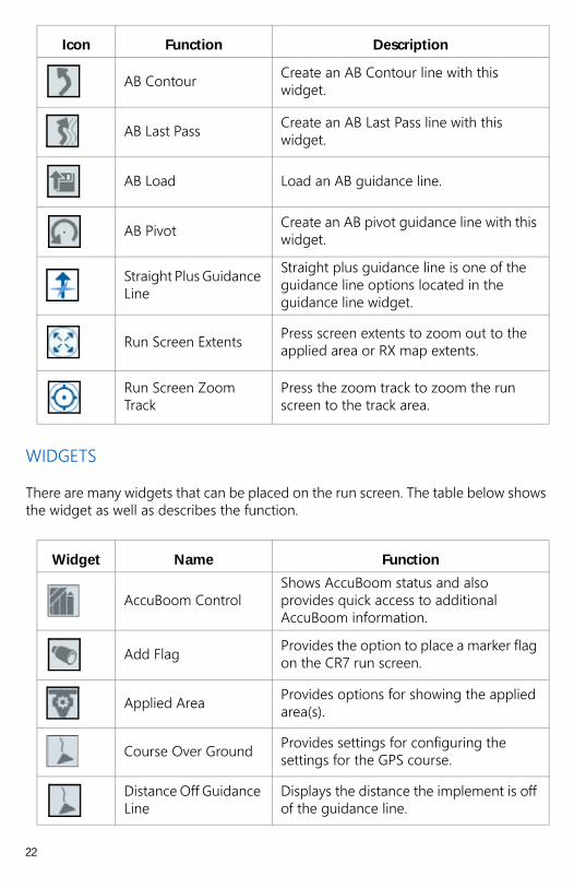
WIDGETS
There are many widgets that can be placed on the run screen. The table below shows the widget as well as describes the function.
AB Contour Create an AB Contour line with this widget.
AB Last Pass Create an AB Last Pass line with this widget.
AB Load Load an AB guidance line.
AB Pivot Create an AB pivot guidance line with this widget.
Straight Plus Guidance Line
Straight plus guidance line is one of the guidance line options located in the guidance line widget.
Run Screen Extents Press screen extents to zoom out to the applied area or RX map extents.
Run Screen Zoom Track
Press the zoom track to zoom the run screen to the track area.
Widget Name Function
AccuBoom ControlShows AccuBoom status and also provides quick access to additional AccuBoom information.
Add Flag Provides the option to place a marker flag on the CR7 run screen.
Applied Area Provides options for showing the applied area(s).
Course Over Ground Provides settings for configuring the settings for the GPS course.
Distance Off Guidance Line
Displays the distance the implement is off of the guidance line.
Icon Function Description
22

To add/change the widgets visible on the run screen:
1. Press the Widget Configuration widget.2. Select or deselect the desired widgets from the list.3. Long pressing some of the widgets will open the widget bubble. For some
widgets, a widget options bubble will open. This gives the user an opportunity to move, minimize, or delete a widget. It also provides options to adjust the settings for the product/feature widget.
Guidance Line Nudge Provides settings for nudging the guidance line left or right.
Line Recal Provides options for recalibrating the guidance line.
Master Switch Indicates if the master switch is on (green) or off (red).
Product Rate Allows the user to adjust the product rate.
Product Select Allows the user to select different products.
Section StatusAvailable in various widths and allows the operator to select the best option for displaying configured sections.
SmarTrax StatusAdd the SmarTrax widget to easily access view SmarTrax status or access SmarTrax Settings.
Swath Width Status Shows if the swatch width is currently enabled.
Widget Name Function
Move Widget
Minimize Widget
Delete Widget
Settings
23

SCOUTING OBJECTS
Scouting objects allows the user to create or mark different areas of the field to indicate obstacles, low spots, or field boundaries. The following options are available for Scouting Objects:
• Create a Field Boundary to indicate the edges of the field.• Do Not Apply Zone is used to indicate a wet spot in the field or an area where
application is not needed.• Application Zone is used to indicate the outside edges of the desired application
area.• Line is used to create a line to follow which can indicate a change in crop type or
property lines.• Flags are used to indicate large rocks or other obstacles that may be present in the
field but may not be visible with mature crops.
CREATING A FLAG
1. Select Scout Object icon.
2. Select the Add icon next to Scout Features.3. Enter the desired name. In this case, Enter Flag Name.
4. Select the desired recording point for the flag. It can be either centered with the implement, or on either side of the implement.
5. Select Create Flag .
24
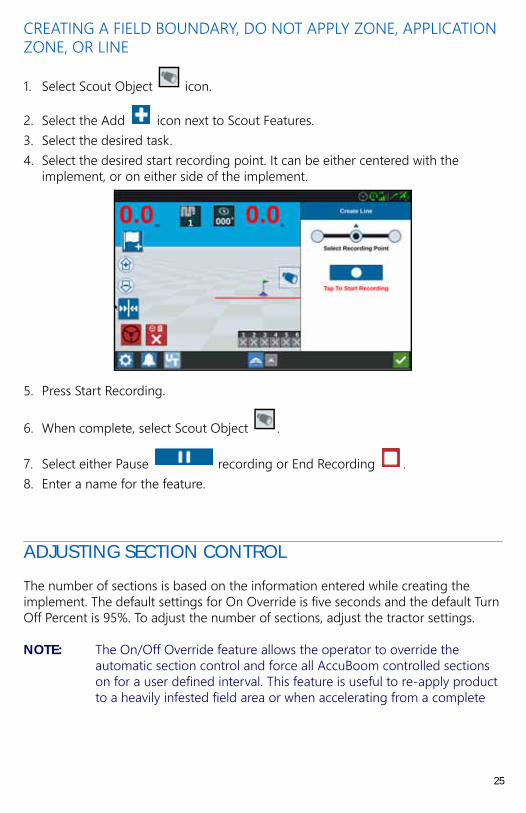
CREATING A FIELD BOUNDARY, DO NOT APPLY ZONE, APPLICATION ZONE, OR LINE
1. Select Scout Object icon.
2. Select the Add icon next to Scout Features.3. Select the desired task. 4. Select the desired start recording point. It can be either centered with the
implement, or on either side of the implement.
5. Press Start Recording.
6. When complete, select Scout Object .
7. Select either Pause recording or End Recording .8. Enter a name for the feature.
ADJUSTING SECTION CONTROL
The number of sections is based on the information entered while creating the implement. The default settings for On Override is five seconds and the default Turn Off Percent is 95%. To adjust the number of sections, adjust the tractor settings.
NOTE: The On/Off Override feature allows the operator to override the automatic section control and force all AccuBoom controlled sections on for a user defined interval. This feature is useful to re-apply product to a heavily infested field area or when accelerating from a complete
25
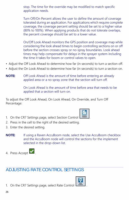
stop. The time for the override may be modified to match specific application needs.
Turn Off/On Percent allows the user to define the amount of coverage tolerated during an application. For applications which require complete coverage, the coverage percent setting should be set to a higher value (80% to 100%). When applying products that do not tolerate overlaps, the percent coverage should be set to a lower value.
On/Off Look Ahead monitors the GPS position and coverage map while considering the look ahead times to begin controlling sections on or off before the section crosses spray or no-spray boundaries. Look ahead times may help compensate for delays in the sprayer system including the time it takes for boom or control valves to open.
• Adjust the Off Look Ahead to determine how far (in seconds) to turn a section off.• Adjust the On Look Ahead to determine how far (in seconds) to turn a section on.
NOTE: Off Look Ahead is the amount of time before entering an already applied area or a no spray zone that the section will turn off.
On Look Ahead is the amount of time before area that needs to be applied that a section will turn on.
To adjust the Off Look Ahead, On Look Ahead, On Override, and Turn Off Percentage:
1. On the CR7 Settings page, select Section Control .2. Press in the cell to the right of the desired setting.3. Enter the desired setting.
NOTE: If using a Raven AccuBoom node, select the Use AccuBoom checkbox and the AccuBoom node will control the sections for the implement selected in the drop-down list.
4. Press Accept .
ADJUSTING RATE CONTROL SETTINGS
1. On the CR7 Settings page, select Rate Control .
26

2. Select the desired implement from the drop-down.3. Select the cell next to the Prescription Map Look Ahead.4. Enter the desired look ahead distance (in seconds).
ADJUSTING SETTINGS
DISPLAY SETTINGS
To access display settings:
1. Press Display on the CR7 Settings page. The Display Settings window will open.
2. The default settings for the display are Day Mode with the Screen Brightness and Lightbar Brightness at 100%. If desired, select Night Mode which switches the screen background and foreground colors and sets the Screen Brightness to 30% and Lightbar Brightness to 30%.
3. In Day Mode or Night Mode it is possible to adjust the Screen Brightness or Lightbar Brightness by dragging the slider bar to the desired brightness.
LOCALIZATION
The Localization page provides options to adjust the language, time zone, and measurement units. To access Localization settings:
1. Press Localization on the CR7 Settings screen. The Localization window will open.
2. Select the desired language from the Language drop down.3. Select the desired Time Zone from the drop down.
NOTE: The time zones are based on an offset from Coordinated Universal Time (UTC). Ex. Los Angeles is UTC-08:00, New York is UTC-05:00, Berlin is UTC+01:00, and Moscow is UTC+03:00.
4. For units select USA, Metric, or Turf for Distance. Also select the desired Speed, Area, Weight, Volume and Pressure units.
5. After adjusting all the settings, press Accept .
27

SERIAL PORT INFORMATION
To access serial port information:
1. Press Serial Port on the CR7 Settings screen. The Serial Ports - Port A window will open. Information for the Serial Port such as Baud Rate, Stop Bits, Parity, TX, and RX will display. If needed, select Detect Device to update the information.
2. To access information on other serial ports, select the desired Port from the left side of the window.
3. After viewing the Serial Port information, Press Accept .
GPS
1. Press GPS on the CR7 Settings screen.
2. Press the DIFF tab to view and select GPS Differential Setup information such as available differential Type and PRN.
3. Press the PORT A tab to view and edit information on Port A GPS configuration. If desired, press additional port tabs to view and edit GPS information for those ports. In some cases Port may be referred to as Com.
NOTE: Port A is not configurable.
28
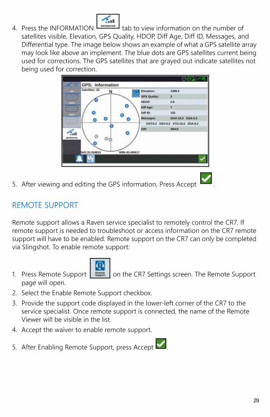
4. Press the INFORMATION tab to view information on the number of satellites visible, Elevation, GPS Quality, HDOP, Diff Age, Diff ID, Messages, and Differential type. The image below shows an example of what a GPS satellite array may look like above an implement. The blue dots are GPS satellites current being used for corrections. The GPS satellites that are grayed out indicate satellites not being used for correction.
5. After viewing and editing the GPS information, Press Accept .
REMOTE SUPPORT
Remote support allows a Raven service specialist to remotely control the CR7. If remote support is needed to troubleshoot or access information on the CR7 remote support will have to be enabled. Remote support on the CR7 can only be completed via Slingshot. To enable remote support:
1. Press Remote Support on the CR7 Settings screen. The Remote Support page will open.
2. Select the Enable Remote Support checkbox. 3. Provide the support code displayed in the lower-left corner of the CR7 to the
service specialist. Once remote support is connected, the name of the Remote Viewer will be visible in the list.
4. Accept the waiver to enable remote support.
5. After Enabling Remote Support, press Accept .
29

MASTER SWITCH CONFIGURATION
1. Press Master Switch on the CR7 Settings screen. The Master Switch Control Configuration window will open.
2. If desired, select the Require All On checkbox. This requires all selected inputs to be On for the Master to be on. Otherwise only one selected input needs to be on.
3. The default for On-Screen checkbox is selected.
NOTE: Aux Input - Select this option if there is a wired switch to the CR7 Aux Input wire to act as a master switch.
AccuBoom - Select this option if there is a wired switch on the AccuBoom cabling orange wire to act as a master switch.
Steering - Select this option if you want the SmarTrax to record data only when steering is engaged.
On-Screen - Only selectable if all other options are not selected.
4. After adjusting all the settings, press Accept .
UNIVERSAL TERMINAL (UT) SETTINGS
The UT Settings page provides options to identify connected UT’s, clear the UT Object Pool or change the UT instance when multiple UT’s are available. To access
the UT Settings page, press UT Settings on the CR7 Settings page.
LIGHTBAR CONFIGURATION
1. To access the Lightbar Configuration settings, press Lightbar . The Lightbar Configuration window will open.
2. The default setting for the lightbar is that it is enabled. To disable the light-bar, deselect the Enable checkbox.
3. The default setting for the Reverse LED Indication is active. To deactivate the Reverse LED Indication, deselect the Reverse LED Indication checkbox.
NOTE: Selecting or deselecting the Reverse LED Indication will change if the lightbar LEDs display to the right if to the right of the guidance line or to the left if to the right of the guidance line.
30

4. The default setting for Path Deviation Sensitivity is Fine. To adjust the Path Deviation Sensitivity select the desired radial button. While adjusting the sensitivity, note that the light bar increments along the bottom indicates the distance off line for each light. For example, with Fine selected the first red light will turn on when the implement is 4” (10 cm) off line, the second light will turn on when the implement is 10” (26 cm) off line.After adjusting all the settings for the
light-bar, press Accept .
If an external lightbar is connected via the serial port, that option will display on the Lightbar Settings page and be selected. If desired, deselect the external lightbar.
NOTIFICATIONS
Press the Notifications button to access the Notification History. To view more information on a specific notification, press the notification. A notification window will open displaying the notification type, additional notification details, and how long ago the notification occurred. After reviewing the notification, press Complete
. When done viewing the notifications, press Accept .
FILE MANAGER
The file manager allows the user to sort and move files (if desired). If the file is currently located on a USB stick, connect to the USB port on the back of the CR7.
FILE TYPES
The table below shows available file types on the CR7.
Icon File Type Description
Scouted ObjectThis icon indicates that the file type is a scouted object which includes Field Boundaries, Zones, Lines and Flags.
Guidance Line This icon indicates the file type is a guidance line.
All Files Select this to select all of the files stored on the device or on the installed USB memory stick.
31
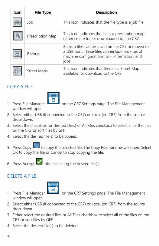
COPY A FILE
1. Press File Manager on the CR7 Settings page. The File Management window will open.
2. Select either USB (if connected to the CR7) or Local (on CR7) from the source drop-down.
3. Select the checkbox for desired file(s) or All Files checkbox to select all of the files on the CR7 or sort files by GFF.
4. Select the desired file(s) to be copied.
5. Press Copy to copy the selected file. The Copy Files window will open. Select OK to copy the file or Cancel to stop copying the file.
6. Press Accept after selecting the desired file(s).
DELETE A FILE
1. Press File Manager on the CR7 Settings page. The File Management window will open.
2. Select either USB (if connected to the CR7) or Local (on CR7) from the source drop-down.
3. Either select the desired files or All Files checkbox to select all of the files on the CR7 or sort files by GFF.
4. Select the desired file(s) to be deleted.
Job This icon indicates that the file type is a job file.
Prescription Map This icon indicates the file is a prescription map either create for, or downloaded to, the CR7.
Backup
Backup files can be saved on the CR7 or moved to a USB port. These files can include backups of machine configurations, GFF information, and jobs.
Street Maps This icon indicates that there is a Street Map available for download to the CR7.
Icon File Type Description
32
5. Press Delete to delete the selected file. The Delete Files window will open. Press OK to delete the file(s) or Cancel to not delete the file.
6. Press Accept after selecting the desired file(s).
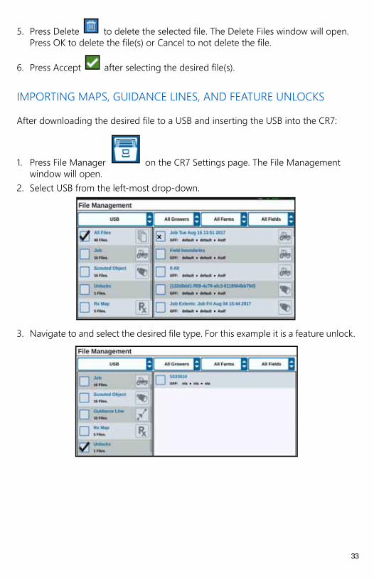
IMPORTING MAPS, GUIDANCE LINES, AND FEATURE UNLOCKS
After downloading the desired file to a USB and inserting the USB into the CR7:
1. Press File Manager on the CR7 Settings page. The File Management window will open.
2. Select USB from the left-most drop-down.
3. Navigate to and select the desired file type. For this example it is a feature unlock.
33
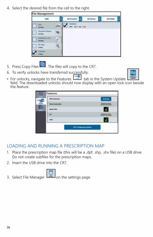
4. Select the desired file from the cell to the right.
5. Press Copy Files . The files will copy to the CR7. 6. To verify unlocks have transferred successfully:• For unlocks, navigate to the Features tab in the System Update
field. The downloaded unlocks should now display with an open lock icon beside the feature.
LOADING AND RUNNING A PRESCRIPTION MAP1. Place the prescription map file (this will be a .dpf, .shp, .shx file) on a USB drive.
Do not create subfiles for the prescription maps. 2. Insert the USB drive into the CR7.
3. Select File Manager on the settings page.
34
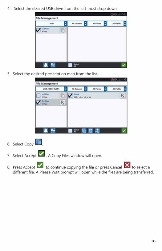
4. Select the desired USB drive from the left-most drop down.
5. Select the desired prescription map from the list.
6. Select Copy .
7. Select Accept . A Copy Files window will open.
8. Press Accept to continue copying the file or press Cancel to select a different file. A Please Wait prompt will open while the files are being transferred.
35

9. Start a job. On the Coverage to Implement Assignment screen select Edit beside the desired prescription map.
10. Select the desired prescription map from the No Rx Map drop-down.11. Select Rate from the <Select Rate Column> drop-down.
12. If needed, adjust the units and conversion factor.
13. Press Accept . The Coverage to Implement Assignment window will open showing the Rx Control for the product.
36
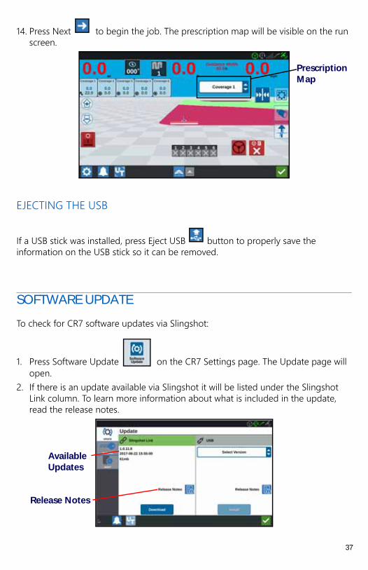
14. Press Next to begin the job. The prescription map will be visible on the run screen.
EJECTING THE USB
If a USB stick was installed, press Eject USB button to properly save the information on the USB stick so it can be removed.
SOFTWARE UPDATE
To check for CR7 software updates via Slingshot:
1. Press Software Update on the CR7 Settings page. The Update page will open.
2. If there is an update available via Slingshot it will be listed under the Slingshot Link column. To learn more information about what is included in the update, read the release notes.
Prescription Map
Available Updates
Release Notes
37

3. To install the update, press download. The update will download to the CR7. After the CR7 update has downloaded, the Download button will change to Install. Press Install to install the software update.
4. If desired, press the Features tab to access the desired unlock. The following options are available:
• GPS Unlocks: Unlock to access more precise GPS corrections.• Task Controller: The task controller unlock is required to allow the UT to
automatically control sections. • Multi-VRA: Unlock Multi-VRA to use prescription maps to automatically apply
multiple products to a field.• UT: UT allows the user to monitor and adjust nodes connected to the ISOBUS
network. • VRA: Unlock VRA to use a prescription map to automatically apply the desired
product as configured in the prescription map.
5. If desired, press the About tab to view information about the CR7 including the software version, when the software version was installed, Run Hours, and Total Run Hours. If desired, press Erase Data to reset the system and erase all data stored on the CR7. This includes all implements, Grower/Farm/Field data, and settings on the CR7.
6. After adjusting all the settings, press Accept .
DOWNLOADING A CR7 UPDATE TO USB
To locate and download a CR7 software update to a USB stick:
1. On a computer, enter http://portal.ravenprecision.com/ into the address bar.2. Press Enter.3. Click Product Documentation.4. Click CR7.5. Navigate to the dropdown.6. Select the desired Software.
NOTE: If desired, review the download and installation instructions.
7. Select Save As from the Save dropdown.8. Select the desktop as the desired save location.9. Press Save.10. Create a folder on the computer desktop named “Raven” with a folder named
“Updates” inside.
38

11. Place the software update in the folder created in step 10.12. Transfer the software download to the USB stick.
INSTALLING CR7 UPDATES VIA USB
To apply a software update to the CR7 device:
1. Insert the USB flash drive with the CR7 update in the required folder into the CR7 device.
2. Once the update file is detected on the USB drive, select the desired update from the USB drop down list then press Install.
SMARTRAX SYSTEM INFORMATION
The SmarTrax System Information page provides options for adjusting sensitivity, performing diagnostics, and general SmarTrax information. For SmarTrax operation and calibration information, refer to the appropriate SmarTrax Calibration and Operation Manual.
FEATURE UNLOCKS
Some CR7 features are locked, or temporarily unlocked, when shipped. These features include:
• VRA: Uses a prescription map to automatically apply the desired product as configured in the prescription map.
• Multi-VRA: Uses prescription maps to automatically apply multiple products to a field.
• Task Controller: Task controller is required to allow the CR7 UT to automatically control sections based on field position and previous coverage data collected during the application.
TEMPORARY UNLOCK ACTIVATION
Any temporary unlock will remain active for 20 hours or powered on time after the unlock is activated. The temporary unlock timer will continue until the unlock expires. Once the temporary unlock expires, the feature will be available using the activation package. Contact a local Raven dealer for additional assistance with temporary unlocks or feature activation.
To activate a temporary unlock:
39
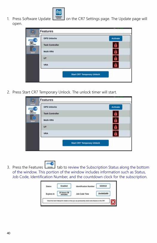
1. Press Software Update on the CR7 Settings page. The Update page will open.
2. Press Start CR7 Temporary Unlock. The unlock timer will start.
3. Press the Features tab to review the Subscription Status along the bottom of the window. This portion of the window includes information such as Status, Job Code, Identification Number, and the countdown clock for the subscription.
40
ENTERING A PERMANENT UNLOCK
Permanent unlocks must be purchased through a Raven dealer. After purchasing the unlocks the files are loaded to the CR7 with a USB drive. To install a permanent unlock on the CR7:
1. Locate the file sent to you from the Raven dealer.2. On a computer, create a folder named Raven.3. Transfer the unlock file to the Raven folder.4. Install a USB drive into one of the USB ports on the computer.5. Transfer the Raven folder to the USB drive.6. Insert the USB drive into the CR7.
7. On the Raven settings screen, select File Manager . 8. Select USB from the left drop-down. 9. Select the unlock file.
10. Select Copy . 11. Restart the CR7 after the files have transferred.
SYSTEM SHUTDOWN
1. To turn off the system, press the System Shutdown button or press the power button on the back of the CR7. A Confirm Shutdown window will open.
2. Press Accept to turn off the system or Cancel to return to the CR7 Settings screen.
41
016-0171-537 Rev. H, E19889
We S
olv
e G
reat
Ch
allen
ges.
LIMITED WARRANTY
WHAT DOES THIS WARRANTY COVER?
This warranty covers all defects in workmanship or materials in your
Raven Applied Technology Division product under normal use,
maintenance, and service when used for intended purpose.
HOW LONG IS THE COVERAGE PERIOD? Raven Applied Technology products are covered by this warranty for
12 months from the date of retail sale. In no case will the Limited
Warranty period exceed 36 months from the date the product was
issued by Raven Industries Applied Technology Division. This warranty
coverage applies only to the original owner and is non-transferable.
HOW CAN I GET SERVICE? Bring the defective part and proof of purchase to your Raven dealer. If
the dealer approves the warranty claim, the dealer will process the
claim and send it to Raven Industries for final approval. The freight cost
to Raven Industries will be the customer’s responsibility. The Return
Materials Authorization (RMA) number must appear on the box and all
documentation (including proof of purchase) must be included inside
the box to be sent to Raven Industries.
WHAT WILL RAVEN INDUSTRIES DO? Upon confirmation of the warranty claim, Raven Industries will (at our
discretion) repair or replace the defective product and pay for the
standard return freight, regardless of the inbound shipping method.
Expedited freight is available at the customer’s expense.
016-0171-536 Rev. B, E19889
We S
olv
e G
reat
Ch
allen
ges.
EXTENDED WARRANTY
WHAT DOES THIS WARRANTY COVER? This warranty covers all defects in workmanship or materials in your
Raven Applied Technology Division product under normal use,
maintenance, and service when used for intended purpose.
DO I NEED TO REGISTER MY PRODUCT TO
QUALIFY FOR
THE EXTENDED WARRANTY? Yes. Products/systems must be registered within 30 days of retail sale
to receive coverage under the Extended Warranty. If the component
does not have a serial tag, the kit it came in must be registered instead.
WHERE CAN I REGISTER MY PRODUCT FOR THE
EXTENDED WARRANTY? To register, go online to www.ravenhelp.com and select Product
Registration.
HOW LONG IS THE EXTENDED WARRANTY
COVERAGE PERIOD? Raven Applied Technology products that have been registered online
are covered for an additional 12 months beyond the Limited Warranty
for a total coverage period of 24 months from the date of retail sale. In
no case will the Extended Warranty period exceed 36 months from the
date the product was issued by Raven Industries Applied Technology
division. This Extended Warranty coverage applies only to the original
owner and is non-transferable.
016-0171-536 Rev. B, E19889
We S
olv
e G
reat
Ch
allen
ges.
HOW CAN I GET SERVICE? Bring the defective part and proof of purchase to your Raven dealer. If
the dealer approves the warranty claim, the dealer will process the
claim and send it to Raven Industries for final approval. The freight cost
to Raven Industries will be the customer’s responsibility. The Return
Materials Authorization (RMA) number must appear on the box and all
documentation (including proof of purchase) must be included inside
the box to be sent to Raven Industries. In addition, the words
“Extended Warranty” must appear on the box and all documentation if
the failure is between 12 and 24 months from the retail sale.
WHAT WILL RAVEN INDUSTRIES DO? Upon confirmation of the product’s registration for the Extended
Warranty and the claim itself, Raven Industries will (at our discretion)
repair or replace the defective product and pay for the standard return
freight, regardless of the inbound shipping method. Expedited freight
is available at the customer’s expense.
WHAT IS NOT COVERED BY THE EXTENDED
WARRANTY? Raven Industries will not assume any expense or liability for repairs
made outside our facilities without written consent. Raven Industries is
not responsible for damage to any associated equipment or products
and will not be liable for loss of profit, labor, or other damages. Cables,
hoses, software enhancements, and remanufactured items are not
covered by this Extended Warranty. The obligation of this warranty is in
lieu of all other warranties, expressed or implied, and no person or
organization is authorized to assume any liability for Raven Industries.
Damages caused by normal wear and tear, misuse, abuse, neglect,
accident, or improper installation and maintenance are not covered
by this warranty.

016-0171-537 Rev. H, E19889
We S
olv
e G
reat
Ch
allen
ges.
WHAT IS NOT COVERED BY THIS WARRANTY? Raven Industries will not assume any expense or liability for repairs
made outside our facilities without written consent. Raven Industries is
not responsible for damage to any associated equipment or products
and will not be liable for loss of profit, labor, or other damages. The
obligation of this warranty is in lieu of all other warranties, expressed or
implied, and no person or organization is authorized to assume any
liability for Raven Industries.
Damages caused by normal wear and tear, misuse, abuse, neglect,
accident, or improper installation and maintenance are not covered
by this warranty.