CR LAURENCE ALUMINUM RAIL SYSTEM (ARS) 3/26/14 Page 1 of ...
48
26 March 2014 Architectural Railing Division C.R.Laurence Co., Inc. 2503 E Vernon Ave. Los Angeles, CA 90058 (T) 800.421.6144 (F) 800.587.7501 www.crlaurence.com SUBJ: ARS – ALUMINUM RAILING GLASS INFILL SYSTEMS SERIES 100, 200, 300, 350 AND 400 SERIES SYSTEMS The ARS Aluminum Railing System utilizes aluminum extrusions and glass infill to construct building guards and rails for decks, balconies, stairs, fences and similar locations. The system is intended for interior and exterior weather exposed applications and is suitable for use in all natural environments. The ARS may be used for residential, commercial and industrial applications. The ARS is an engineered system designed for the following criteria: The design loading conditions are: On Top Rail: Concentrated load = 200 lbs any direction, any location Uniform load = 50 plf, any perpendicular to rail On In-fill Panels: Concentrated load = 50# on one sf. Distributed load = 25 psf on area of in-fill, including spaces Wind load = 28.5 psf (ASD level) typical installation (higher wind loads may be allowed based on post spacing and anchorage method) Refer to IBC Section 1607.7.1 for loading. The ARS Glass Infill system will meet all applicable requirements of the 2006, 2009 and 2012 International Building Codes, Florida Building Code (non-hurricane zones), 2010 and 2013 California Building Codes and 2005 Aluminum Design Manual. Stainless steel components are designed in accordance with SEI/ASCE 8-02 Specification for the Design of Cold-Formed Stainless Steel Structural Members or AISC Design Guide 27 Structural Stainless Steel as applicable. Wood components and anchorage to wood are designed in accordance with the National Design Specification for Wood Construction. The ARS system exceeds the requirements of ASTM E 2358-04 Standard Specification for The Performance of Glass in Permanent Glass Railing Systems Guards and Balustrades and ICC AC273 Acceptance Criteria for Handrails and Guards. ASTM E985-00 is not applicable to this railing system. Edward Robison, P.E. CR LAURENCE ALUMINUM RAIL SYSTEM (ARS) 3/26/14 Page 1 of 48 EDWARD C. ROBISON, PE 10012 Creviston Dr NW Gig Harbor, WA 98329 253-858-0855/Fax 253-858-0856 [email protected]
Transcript of CR LAURENCE ALUMINUM RAIL SYSTEM (ARS) 3/26/14 Page 1 of ...

26 March 2014Architectural Railing DivisionC.R.Laurence Co., Inc.2503 E Vernon Ave.Los Angeles, CA 90058(T) 800.421.6144(F) 800.587.7501www.crlaurence.com
SUBJ: ARS – ALUMINUM RAILING GLASS INFILL SYSTEMS SERIES 100, 200, 300, 350 AND 400 SERIES SYSTEMS
The ARS Aluminum Railing System utilizes aluminum extrusions and glass infill to construct building guards and rails for decks, balconies, stairs, fences and similar locations. The system is intended for interior and exterior weather exposed applications and is suitable for use in all natural environments. The ARS may be used for residential, commercial and industrial applications. The ARS is an engineered system designed for the following criteria: The design loading conditions are:On Top Rail: Concentrated load = 200 lbs any direction, any location Uniform load = 50 plf, any perpendicular to rail
On In-fill Panels: Concentrated load = 50# on one sf. Distributed load = 25 psf on area of in-fill, including spaces Wind load = 28.5 psf (ASD level) typical installation (higher wind loads may be allowed based on post spacing and anchorage method)Refer to IBC Section 1607.7.1 for loading.
The ARS Glass Infill system will meet all applicable requirements of the 2006, 2009 and 2012 International Building Codes, Florida Building Code (non-hurricane zones), 2010 and 2013 California Building Codes and 2005 Aluminum Design Manual. Stainless steel components are designed in accordance with SEI/ASCE 8-02 Specification for the Design of Cold-Formed Stainless Steel Structural Members or AISC Design Guide 27 Structural Stainless Steel as applicable. Wood components and anchorage to wood are designed in accordance with the National Design Specification for Wood Construction. The ARS system exceeds the requirements of ASTM E 2358-04 Standard Specification for The Performance of Glass in Permanent Glass Railing Systems Guards and Balustrades and ICC AC273 Acceptance Criteria for Handrails and Guards. ASTM E985-00 is not applicable to this railing system.
Edward Robison, P.E.
CR LAURENCE ALUMINUM RAIL SYSTEM (ARS) 3/26/14 Page 1 of 48
EDWARD C. ROBISON, PE10012 Creviston Dr NWGig Harbor, WA 98329
253-858-0855/Fax 253-858-0856 [email protected]

CONTENTS:Item PageSignature Page 3Typical Installations 4Load Case 5Wind Loading on Balcony Rails 6Glass Strength 7 - 10Standard 2 3/8” Square Post 11Standard Base Plate Connection 12Standard Base Plate Anchorage 13Anchorage to Concrete 14Raised Base Plate 15Offset Base Plate 16Base Plate to Wood 17Core Mounted Post 18Fascia Bracket 19 - 20Corner Fascia Brackets 21Direct Fascia Mounted Post 22 - 23Stanchion Mount 24Base Plate Mounted Stanchion 25135˚ Post – Corner Post 26Series 100 Top Rail 27
Item PageSeries 100 Bottom Rail 28Intermediate Bottom Support 29Rail to Post Face Connection 29Intermediate Post Fitting 30Series 200 Top Rail 31Series 300 Top Rail 32Insert Channel for Picket Infill 33Adjustable Fastening Plates 34Rail Splices 35Series 350 Top Rail 36Series 400 Top Rail 37Mid Rail 38Picket Bottom Rail 39Wind Screen Mid Rail 40Post Rail Connection Block 41Wall Mounted End Caps 42 – 434”x4” Square Post 446-1/2” Base Plate for 4” Post 45 - 464x4 Post Rail Components 47Lag Screw Withdrawal/shear 48
CR LAURENCE ALUMINUM RAIL SYSTEM (ARS) 3/26/14 Page 2 of 48
EDWARD C. ROBISON, PE10012 Creviston Dr NWGig Harbor, WA 98329
253-858-0855/Fax 253-858-0856 [email protected]

Signature Page:
CR LAURENCE ALUMINUM RAIL SYSTEM GLASS INFILL (ARS) Page 3 of 48 3/26/14
EDWARD C. ROBISON, PE10012 Creviston Dr NWGig Harbor, WA 98329
253-858-0855/Fax 253-858-0856 [email protected]
edwardrobison
Typewritten Text
Signed 03/26/2014

Typical Installations:
Surface mounted with base plates:Residential Applications:Rail Height 36” above finish floor.Standard Post spacing 6’ on center maximum.
Bottom rail intermediate post required over 5’.All top rails
4” x 4” Post spacing up to 6’ on center for Series 1008’ on center for Series 200, 300, 350 and 400.Bottom rail intermediate post required over 5’.
Commercial and Industrial Applications:Rail Height 42” above finish floor.Standard Post spacing 5’ on center maximum.All top rails
4” x 4” Post spacing up to 5’ on center for Series 1008’ on center for Series 200, 300, 350 and 400.Bottom rail intermediate post required over 5’.
Core pocket /embedded posts or stainless steel stanchion mounted:Residential Applications:Rail Height 36” above finish floor.Standard Post spacing 6’ on center maximum, series 100
8’ on center Series 200, 300, 350 and 400. Bottom rail intermediate post required over 5’.
4” x 4” Post spacing up to 7’ on center for Series 10010’ on center for Series 200, 300, 350 and 400, bottom rail intermediate post required.
Commercial and Industrial Applications:Rail Height 42” above finish floor.Standard Post spacing 6’ on center maximum, series 100 6’ on center Series 200, 300, 350 and 400.
4” x 4” Post spacing up to 7’ on center for Series 10010’ on center for Series 200, 300, 350 and 400, Bottom rail intermediate post required over 5’.
CR LAURENCE ALUMINUM RAIL SYSTEM GLASS INFILL (ARS) Page 4 of 48 3/26/14
EDWARD C. ROBISON, PE10012 Creviston Dr NWGig Harbor, WA 98329
253-858-0855/Fax 253-858-0856 [email protected]

LOAD CASES:Glass rail Dead load = 5 plf for 42” rail height or less for frame plus glass weight.Loading:Horizontal load to top rail from in-fill:25 psf*H/2 Post momentsMi = 25 psf*H*S*H/2 = = 12.5*S*H2
For top rail loads:Mc = 200#*HMu = 50plf*S*HFor wind load surface area:Mw = w psf*H*S*H*0.55 = = 0.55w*S*H2
Solving for w :w = 2M/( S*H2)Wind load equivalent for 42” rail height, 5’ post spacing 50 plf top rail load:Mu = 50plf*5’*3.5’ = 875#’ = 10,500#”w = 875/( 0.55*5*3.52) = 26.0 psfAllowable wind load adjustment for other post spacing:w = 26.0*(5/S)For example if post spacing is reduced to 4’6” on center the allowable wind load is”w4.5’ = 26.0*5/4.5 = 29.4 psfand for 4’ spacing:w4’ = 26.0*5/4 = 32.5 psf All wind loads are ASD level. Strength level wind loads calculated using ASCE/SEI 7-10 (2012 IBC) shall be adjusted to ASD level by multiplying by 0.60 (ASCE/SEI 7-10 section 2.4)
NOTES ON ASTM E 2358-04:The loads given in ASTM E 2358-04 are test loads not allowable or service loads. The greatest test load of 365# concentrated load is less than the 500# ultimate load to which the 200# concentrated design live load in these calculations equates.
Compliance with ASTM E 2358-04 while not directly demonstrated by testing is inferred from these calculations since all component strengths and applicable deflections are demonstrated as adequate to meet all testing criteria.
The test loads listed in ASTM E 2358-04 do not meet the test load requirements of IBC 1714.3.1 or ICC AC273 Acceptance Criteria For Handrails and Guards. The engineering herein demonstrates the system has adequate strength to meet the test loads in IBC 1714.3 and AC273.
CR LAURENCE ALUMINUM RAIL SYSTEM GLASS INFILL (ARS) Page 5 of 48 3/26/14
EDWARD C. ROBISON, PE10012 Creviston Dr NWGig Harbor, WA 98329
253-858-0855/Fax 253-858-0856 [email protected]

WIND LOADINGFor wind load surface area is full area of guard:Calculated in accordance with ASCE/SEI 7-05 Section 6.5.14 Design Wind Loads on Solid Freestanding Walls and Solid Signs (or ASCE/SEI 7-10 Chapter 29.4). This section is applicable for free standing building guardrails, wind walls and balcony railings that return to building walls. Section 6.5.12.4.4 (29.6) Parapets may be applicable when the rail is along a roof perimeter. Wind loads must be determined by a qualified individual for a specific installation. p = qp(GCp) = qzGCf (ASCE 7-05 eq. 6-26 or 7-10 eq. 29.4-1)G = 0.85 from section 6.5.8.2 (sec 26.9.4.)Cf = 2.5*0.8*0.6 = 1.2 Figure 6-20 (29.4-1) with reduction for solid and end returns, will vary.Qz = KzKztKdV2I Where: I = 1.0 Kz from Table 6-3 (29.3-1) at the height z of the railing centroid and exposure. Kd = 0.85 from Table 6-4 (Table 26-6). Kzt From Figure 6-4 (Fig 26.8-1) for the site topography, typically 1.0.
V = Wind speed (mph) 3 second gust, Figure 6-1 (Fig 26.5-1A) or per local authority.Simplifying - Assuming 1.3 ≤ Cf ≤ 2.6 (Typical limits for fence or guard with returns.)
For Cf = 1.3: F = qh*0.85*1.3 = 1.11 qhFor Cf = 2.6: F = qh*0.85*2.6 = 2.21qh
Wind Load will vary along length of fence in accordance with ASCE 7-05 Figure 6-20 (29.4-1).Typical exposure factors for Kz with height 0 to 15’ above grade:Exposure B C DKz = 0.70 0.85 1.03MINIMUM WIND LOAD TO BE USED IS 10 PSF.Centroid of wind load acts at 0.55h on the fence.Typical wind load range for I = 1.0 and Kzt = 1.0Table 1: Wind load in psf Cf = 1.3 Wind load in psf Cf = 2.60Wind Speed B C D B C DV 0.00169V2 0.00205V2 0.00249V2 0.00337V2 0.00409V2 0.00495V2
85 12.2 14.8 17.9 24.3 29.5 35.890 13.7 16.6 20.2 27.3 33.1 40.1100 16.9 20.5 24.9 33.7 36.9 49.5110 20.5 24.8 30.1 40.7 49.5 59.9120 24.3 29.6 35.8 48.5 58.9 71.3130 28.6 34.7 42.0 56.9 69.1 83.7140 33.1 40.2 48.8 66.0 80.1 97.1Where fence ends without a return the wind forces may be as much as 1.667 times Cf=2.6 value.When I = 0.87 is applicable (occupancy category I) multiply above loads by 0.87.For wind loads based on ASCE 7-10 wind speeds, figures 26.5-1A, B and C, multiply the wind loads by 0.6 to convert to Allowable Stress Design loads.For example - Exp B with Cf = 1.3; 7-05 wind speed = 85 mph w= 12.2 psf:7-10 wind speed= 110mph w = 0.6*20.5 = 12.3 psf (ASD wind loads used herein)
CR LAURENCE ALUMINUM RAIL SYSTEM GLASS INFILL (ARS) Page 6 of 48 3/26/14
EDWARD C. ROBISON, PE10012 Creviston Dr NWGig Harbor, WA 98329
253-858-0855/Fax 253-858-0856 [email protected]

GLASS STRENGTH FULLY TEMPERED INFILL PANELSAll glass is fully tempered glass conforming to the specifications of ANSI Z97.1, ASTM C 1048-97b and CPSC 16 CFR 1201. The average Modulus of Rupture for the glass Fr is 24,000 psi, Fr = 24 ksi typically used for design purposes. In accordance with IBC 2407.1.1 glass used as structural balustrade panels shall be designed for a safety factor of 4.0. Glass not used in guardrails may be designed for a lesser safety factor in accordance with ASTM E1300.
Values for the modulus of rupture, Fr, modulus of Elasticity, E and shear modulus, G for glass based on AAMA CW-12-84 Structural Properties of Glass (values are consistent with those used in ASTM E1300) are typically taken as:
Fr = 24,000 psi E = 10,400 ksi is used as the standard value for common glass. While the value of E for
glass varies with the stress and load duration this value is typically used as an average value for the stress range of interest.
G = 3,800 ksi: The shear component of the deflection tends to be very small, under 1% of the bending component and is therefore ignored.
µ = 0.22 Typical value of Poisson’s ratio for common glasses.ν = 5x10⁻⁶ in/(inF˚) Typical coefficient of thermal expansion.
The safety factor of 4 is dictated by the building code (IBC 2407.1.1). It is applied to the modulus of rupture since glass as an inelastic material does not have a yield point.
There is no deflection limits for the glass in guards other than practical limits for the opening sizes, retention in the frames and occupant comfort. Refer to ASTM E 1300-12a for a standard method of calculating deflections but the deflection limits are concerned with glazing in windows and similar parts of the building envelope rather than a free standing guard. IBC 2403.3 applies a limit of L/175 or 3/4” on the supporting frame for glass to be considered as fully supported along the frame element. From IBC Table 1604.3 footnote h similar types of construction have a limit of L/60.
The shear strength of glass tracks closely to the modulus of rupture because failure under shear load will be a tensile failure with strength limited by the modulus of rupture. Thus shear loads are transformed using Mohr’s circle to determine the critical tension stress to evaluate the failure load. The safety factor of 4 is applicable to this case same as the bending case. Thus the shear stress is limited based on principal stresses of 0 and 6,000 psi to 6,000/2 = 3,000 psi. Bearing stress can be derived in a similar fashion with the principal stresses being –6,000 psi and 6,000 psi so the bearing stress = 6,000 psi.
Bending strength of glass for the given thickness: I = 12”*(t)3 /12= (t)3 in3/ft S = 12”*(t)2 /6= 2*(t)2 in3/fttave = Average glass thickness; tmin = minimum glass thickness allowed by standard
CR LAURENCE ALUMINUM RAIL SYSTEM GLASS INFILL (ARS) Page 7 of 48 3/26/14
EDWARD C. ROBISON, PE10012 Creviston Dr NWGig Harbor, WA 98329
253-858-0855/Fax 253-858-0856 [email protected]

For lites simply supported on two opposite sides the moment and deflection are calculated from basic beam theory Mw = W*L2/8 for uniform load W and span L or Mp = P*L/4 for concentrated load P and span L, highest moment P @ centerMaximum wind loads: W = Ma*8/L2 for uniform load W and span L (rail to rail distance)
Deflection can be calculated using basic beam theory: Δ = (1-ν2)5wL4/(384EI) for uniform load (1-ν2) = 0.9516Simplifying: Δ = [wL4/t3]/(10.07 x 109)for w in psf and L in inchesFor concentrated load: Δ = (1-ν2) PL3/(48EI)Simplifying: Δ = PL3/(5.246*108t3)
Maximum allowable deflection: Use L/60 deflection limit for infill. This will prevent glass from deflecting enough to disengage from the frame.For uniform load (wind load)Solving for w w = [t3*1.676*108]/L3
Solving for L L = [(t3*1.676*108)/w]1/3
Solving for t t = [L3w/(1.676*108)]1/3
For Concentrated loadSolving for P P = (8.74*106t3)/L2
Solving for L L = [8.74*106*t3/P]1/2
Solving for t t = [PL2/(8.74*106)]1/3
NOTE ON GLASS THICKNESS:This report uses the average glass thickness from ASTM C1036 Standard Specification for Flat Glass. Actual glass thickness may be less than the value assumed herein.
CR LAURENCE ALUMINUM RAIL SYSTEM GLASS INFILL (ARS) Page 8 of 48 3/26/14
EDWARD C. ROBISON, PE10012 Creviston Dr NWGig Harbor, WA 98329
253-858-0855/Fax 253-858-0856 [email protected]

From IBC 2407 the minimum nominal glass thickness for infill panels in guards is 1/4”
1/4” FULLY TEMPERED GLASSWeight = 2.89 psftave = 0.223”
For 1/4” glass S = 2*(0.223)2 = 0.0995 in3/ft Mallowable = 6,000psi*0.0995 in3/ft = 597#”/ftFor FS = 3.0 (no fall hazard, glass fence or wind screen) Mall = 597”#*4/3 = 796”#
Moment for 36” wide lite (infill for 42” rail height) 25 psf or 50 lb load Mw = 25psf*3’2*12”/’/8= 337.5”# Mp = 50*36”/4 = 450”#Moment for 42” wide lite (infill for 48” rail height) 25 psf or 50 lb load Mw = 25psf*3.5’2*12”/’/8= 459.4”# Mp = 50*42”/4 = 525”#
for 36” wide lite (infill for 42” rail height) W = 597”#*8/(3’*36”)= 44 psf for 42” wide lite (infill for 48” rail height) W = 597”#*8/(3.5’*42”)= 32.5 psf
Deflection:36” wide lite (infill for 42” rail height) 25 psf or 50 lb load L/60 = 36/60 = 0.60 Δ = [25*364/0.253]/(10.07 x 109) = 0.27”or Δ = 50*363/(5.246*108*0.253) = 0.285”
CR LAURENCE ALUMINUM RAIL SYSTEM GLASS INFILL (ARS) Page 9 of 48 3/26/14
EDWARD C. ROBISON, PE10012 Creviston Dr NWGig Harbor, WA 98329
253-858-0855/Fax 253-858-0856 [email protected]

3/8” FULLY TEMPERED GLASSWeight = 4.75 psitave = 0.366”
For 3/8” glass S = 2*(0.366)2 = 0.268 in3/ft Mallowable = 6,000psi*0.268 in3/ft = 1,607#”/ftFor FS = 3.0 (no fall hazard, glass fence or wind screen) Mall = 1,607”#*4/3 = 2,143#”
Moment for 36” wide lite (infill for 42” rail height) 25 psf or 50 lb load Mw = 25psf*3’2*12”/’/8= 337.5”# Mp = 50*36”/4 = 450”#Moment for 42” wide lite (infill for 48” rail height) 25 psf or 50 lb load Mw = 25psf*3.5’2*12”/’/8= 459.4”# Mp = 50*42”/4 = 525”#
for 36” wide lite (infill for 42” rail height) W = 1,607”#*8/(3’*36”)= 119 psf for 42” wide lite (infill for 48” rail height) W = 1,607”#*8/(3.5’*42”)= 87.5 psf
Deflection:36” wide lite (infill for 42” rail height) 25 psf or 50 lb load L/60 = 36/60 = 0.60 Δ = [25*364/0.3663]/(9.58 x 109) = 0.089”or Δ = 50*363/(4.992*108*0.3663) = 0.095”
Check maximum wind load based on deflection:
36” width w = [0.3663*1.595*108]/363 = 167 psf (does not control)42” width w = [0.3663*1.595*108]/423 = 105 psf (does not control)
CR LAURENCE ALUMINUM RAIL SYSTEM GLASS INFILL (ARS) Page 10 of 48 3/26/14
EDWARD C. ROBISON, PE10012 Creviston Dr NWGig Harbor, WA 98329
253-858-0855/Fax 253-858-0856 [email protected]

2-3/8” Square Post 6005-T5 (Standard) or 6061-T6
Post-Area 0.995”Ixx = Iyy = 0.863 in4
S = 0.726 in3
r = 0.923 in J = 0.98 in k ≤ 1 for all applications
Allowable bending stress ADM Table 2-21
S1 = LB SC = LB • 0.726 = 1.58 LB 0.5√(Iy J) 0.5√(0.863*0.98)
for LB ≤ 146 = 92” → FCB = 21 ksi 158for LB > 92” FCB= 2.39–0.24(1.58 LB)1/2
POST EXTRUSION ACTUAL SIZEMall = 0.726 • 19ksi = 13,794 #” = 1,149#ft
2.375”
Δ = PL3/(3EI) = PL3/(3*10,100,000psi*0.863in4) = PL3/26,148,900 P1” = 26,148,900/L3 for 42” post height = 353#L1” = (26,148,900/P)1/3 for 250# L = 47”For L/12 (maximum allowable post deflection from ASTM E-985 test loads)P = EI/(4L2): for 42” height:P = 10,100,000psi*0.863in4/(4*422) = 1,235# - Deflection will not control post loads
CR LAURENCE ALUMINUM RAIL SYSTEM GLASS INFILL (ARS) Page 11 of 48 3/26/14
EDWARD C. ROBISON, PE10012 Creviston Dr NWGig Harbor, WA 98329
253-858-0855/Fax 253-858-0856 [email protected]

Connection to base plate
Failure modes → screw tension → screw shear → screw withdrawal
For screw withdrawal See ADM 5.4
W = 2.3 • e • d • π • Fsy
e = full thread engagement = 1”d = max root diameter = 0.248” minor = 0.185”Base plate to post screws are AISI 4037 steel alloy fabricated in accordance with SAE J429 Grade 8 and coated with Magni 550 corrosion protection. Fsy = 20 ksi
W = 2/3 • 1” • 0.248” • π • 20ksi
W = 10.39k
W’ = 10.39 = 3.46k
3.0 Safety factor
Screw tension → Ty = 0.0483 in2 • 110 ksi = 5314 # Vu = 0.0483* 45ksi =2,174#
FtU = 0.0376 • 150 ksi = 5640#
Safety factors for screws calculated from SEI/ASCE 8-02 Section 5 LRFD factorsFor yielding SF = 1.6/0.75 = 2.13 → 5,314#/2.13 = 2,495#
For fracture SF = 1.6/0.65 = 2.46 → 5640/2.46 = 2,293#
Shear strengthFor fracture SF = 1.6/(0.9*0.75) = 2.37 → 5,640/2.37 =2,380#
Base plate bending stress Ft = 24 ksi → Smin = 5” • 3/82 = 0.117 in3
6
4.375"
2.28"
.8125"1.3125"
5"
.375"
Cp Ts
Cb
Tb
CR LAURENCE ALUMINUM RAIL SYSTEM GLASS INFILL (ARS) Page 12 of 48 3/26/14
EDWARD C. ROBISON, PE10012 Creviston Dr NWGig Harbor, WA 98329
253-858-0855/Fax 253-858-0856 [email protected]
Major root area
average root area

Base plate allowable moment Mall = 24 ksi • 0.117 in3 = 2,812 “#
→ Base plate bending stress
TB = C
M = 0.8125” • TB • 2
Tall = 2,812 = 1,730#
2 • 0.8125
Maximum post moment for base plate strengthMall = 2 • 1730 • 4.375” = 15,142#“
Limiting factor = screws to postMult = 2 • 5,314# • 2.28” = 24,232#” Mall = 2 • 2,293# • 2.28” = 10,456”#
When 1/3 stress increase is allowed IBC 1607.7.1.3M1/3 = 10,456 • 4/3 = 13,641#”
For factors of safety refer to Aluminum Design Manual Section 5.3.2.1and SEI/ASCE 8-02 section 5
BASE PLATE ANCHORAGETDes = 10,456 = 1,195#
2 • 4.375”adjustment for concrete bearing pressure:a = 2*1195/(2*3000psi*4.75”) = 0.087”T’Des = 10,456 = 1,206#
2 • (4.375”-0.087/2)
For 200# top load and 42” post htT200 = 8,400 = 960# 2*4.375”
For 42” post height the maximum live load at the top of the post is:Pmax = 10,456”#/42” = 250#
For 50 plf live load maximum post spacing is:Smax = 250#/50 plf = 5.0’ = 5’0”
2 3/8" SQ. AL. TUBE
BUTTON
LOCK NUT
BUTTON WASHER
5x5x3/8 BASE PLATE
BASE PLATE SCREW
3/8 BOLT
CR LAURENCE ALUMINUM RAIL SYSTEM GLASS INFILL (ARS) Page 13 of 48 3/26/14
EDWARD C. ROBISON, PE10012 Creviston Dr NWGig Harbor, WA 98329
253-858-0855/Fax 253-858-0856 [email protected]

BASE PLATE MOUNTED TO CONCRETE - Expansion Bolt Alternative:Base plate mounted to concrete with ITW Red Head Trubolt wedge anchor 3/8”x3.75” concrete anchors with 3” effective embedment. Anchor strength based on ESR-2251Minimum conditions used for the calculations:f’c ≥ 3,000 psiedge distance =2.25” spacing = 3.75”h = 3.0”: embed depthFor concrete breakout strength:Ncb = [ANcg/ANco]ϕed,Nϕc,Nϕcp,NNb
ANcg= (1.5*3*2+3.75)*(1.5*3+2.25) = 86.06 in2 2 anchorsANco= 9*32 = 81 in2
Ca,cmin = 1.5” (ESR-2251 Table 3)Cac = 5.25” (ESR-2251 Table 3)ϕed,N = 1.0 ϕc,N = (use 1.0 in calculations with k = 24) ϕcp,N= max (1.5/5.25 or 1.5*3”/5.25) = 0.857 (ca,min ≤cac)Nb = 24*1.0*√3000*3.01.5 = 6,830#Ncb = 86.06/81*1.0*1.0*0.857*6,830 = 6,219 ≤ 2*3,469based on concrete breakout strength.Determine allowable tension load on anchor pairTs = 0.65*6,219#/1.6 = 2,526#Check shear strength - Concrete breakout strength in shear:Vcb = Avc/Avco(ϕed,Vϕc,Vϕh,VVb
Avc = (1.5*3*2+3.75)*(2.25*1.5) = 43.03Avco= 4.5(ca1)2 = 4.5(2.25)2 = 22.78ϕed,V= 1.0 (affected by only one edge)ϕc,V= 1.4 uncracked concreteϕh,V= √(1.5ca1/ha) = √(1.5*2.25/3) =1.06Vb= [7(le/da)0.2√da]λ√f’c(ca1)1.5 = [7(1.5/0.375)0.2√0.375]1.0√3000(2.25)1.5 =1,046#Vcb = 43.03/22.78*1.0*1.4*1.06*1,046# = 2,931#Steel shear strength = 4,825#*2 = 9,650Allowable shear strengthØVN/1.6 = 0.70*2,931#/1.6 = 1,282#Shear load = 250/1,282 = 0.195 ≤ 0.2Therefore interaction of shear and tension will not reduce allowable tension load:Ma = 2,526#*(4.375”-0.5*2,526/(0.85*1.5*3000*4.75”) = 10,876”# > 10,653”#
ALLOWABLE SUBSTITUTIONS: Use same size anchor and embedmentHilti Kwik Bolt TZ in accordance with ESR-1917Powers Power Stud+ SD2 in accordance with ESR-2502Powers Wedge-Bolt+ in accordance with ESR-2526
CR LAURENCE ALUMINUM RAIL SYSTEM GLASS INFILL (ARS) Page 14 of 48 3/26/14
EDWARD C. ROBISON, PE10012 Creviston Dr NWGig Harbor, WA 98329
253-858-0855/Fax 253-858-0856 [email protected]

RAISED BASEPLATE DESIGN AND ANCHORAGE – Baseplates are raised up and bear on nuts installed on embedded threaded rod.Guard rail Height: 42”loading: 200# concentrated load or 50 plf uniform load on top rail or 25 psf distributed load on area or 25 psf = 80 mph exp C wind load:
Design moment on posts:Ml = 42”*200# = 8,400”#Ml = 42”*50plf*5ft = 10,500”#Mw = 3.5’*5’*25psf*42”/2 = 9,188”#
Design anchorage for 10,500”# moment.Design shear = 438# (wind)
Bolt tension for typical designT =10,500/(2*3.75)=1,400#
Anchor to concrete: 1/2” x 5” all-thread embedment depth = 3.5” and 4,000 psi concrete strength.Allowable loads taken from ER-5560,
T = 2,700# Adjustment for anchor spacing = 3.75”
Cs@ 3.75” = 1-0.20[(5.625-3.75)/4.5] = 0.917Adjustment for edge distance = 2-1/8”Ce = 1-0.30[(3.375-2.125)/2.25] = 0.833T’ = 2,700#*0.917*0.833 = 2,062#
Check base plate strength: Bending is biaxial because it sits on bearing nuts:M = (3.75”-2.28”)/2*1,400#*2*√2 = 2,910”#
4.375"
2.28"
.8125"1.3125"
5"
.375"
Cp Ts
Cb
Tb
VM
3.75"
EE
B
CR LAURENCE ALUMINUM RAIL SYSTEM GLASS INFILL (ARS) Page 15 of 48 3/26/14
EDWARD C. ROBISON, PE10012 Creviston Dr NWGig Harbor, WA 98329
253-858-0855/Fax 253-858-0856 [email protected]

Bending stress in plateThe effective width at the post screws: 3.86”S = 2*3.86”*0.3752/6 = 0.181 in3
fb = 2,910/0.181 = 16,080 psiAllowable = 19 ksi
Bearing on nut:Area = (0.82-0.56252)π = 1.0 in2
fB = 1,400#/1.0 = 1,400 psi - OkayScrews to post – okay based on standard base plate designPosts okay based on standard post design
OFFSET BASE PLATE
Offset base plate will have same allowable loads as the standard base plate.Anchors to concrete are same as for standard base plate.
CR LAURENCE ALUMINUM RAIL SYSTEM GLASS INFILL (ARS) Page 16 of 48 3/26/14
EDWARD C. ROBISON, PE10012 Creviston Dr NWGig Harbor, WA 98329
253-858-0855/Fax 253-858-0856 [email protected]

BASE PLATE MOUNTED TO WOOD – SINGLE FAMILY RESIDENCE
For 200# top load and 36” post height: M = 200#*36” = 7,200”#T200 = 7,200 = 823# 2*4.375” Adjustment for wood bearing:Bearing Area Factor:Cb = (5”+0.375)/5” = 1.075a = 2*823/(1.075*625psi*5”)= 0.49”T = 7,200/[2*(4.375-0.49/2)]= 872#
Required embed depth:
For protected installations the minimum embedment is:le = 872#/323#/in = 2.70” : +7/32” for tip = 2.92”
For weather exposed installations the minimum embedment is:le = 872#/243#/in = 3.59” : +7/32” for tip = 3.81”
FOR WEATHER EXPOSED INSTALLATIONS USE 5” LAG SCREWS AND INCREASE BLOCKING TO 4.5” MINIMUM THICKNESS.
For 200# top load and 42” post height: M = 200#*42” = 8,400”#T200 = 8,400 = 960# 2*4.375” Adjustment for wood bearing:a = 2*960/(1.075*625psi*5”)= 0.572”T = 8,400/[2*(4.375-0.572/2)]= 1,027#
Required embed depth:For protected installations the minimum embedment is:le = 1,027#/323#/in = 3.18” : +7/32” for tip = 3.40” 4.5” minimum lag length.
For weather exposed installations the minimum embedment is:le = 1,027#/243#/in = 4.23” : +7/32” for tip = 4.45”
FOR WEATHER EXPOSED INSTALLATIONS USE 6” LAG SCREWS AND INCREASE BLOCKING TO 5.5” MINIMUM THICKNESS.
3/8” Stainless steel bolts with heavy washers bearing on the wood may be used through the solid wood blocking with a minimum 3” nominal thickness.
CR LAURENCE ALUMINUM RAIL SYSTEM GLASS INFILL (ARS) Page 17 of 48 3/26/14
EDWARD C. ROBISON, PE10012 Creviston Dr NWGig Harbor, WA 98329
253-858-0855/Fax 253-858-0856 [email protected]

Core Mounted Posts
Mounted in either 4”x4”x4” blockout, or 2-3/8” to 6” dia by 4” deep cored hole.
Assumed concrete strength 2,500 psi for existing concrete Max load – 6’•50 plf = 300#
M = 300#•42” = 12,600”#
Check grout reactionsFrom ΣMPL = 0
PU = 12,600”# + 300# • 3.33” = 5,093# 2.67”
fBmax = 5,093#•2 • 1/0.85 = 2,523 psi post to grout 2”•2.375”
fBconc = 2,523 • 2”/4” = 1,262 psi grout to concrete
Core mount okay for 6’ post spacing
MINIMUM EDGE DISTANCE:When #3 or larger rebar is installed along slab edge between the post and slab edge the minimum edge distance from edge of hole to slab edge is 1-1/4”.
When no rebar is present required edge distance: Avco= 4.5(ca1)2 = 4.5(6)2 = 162ϕed,V= 1.0 (affected by only one edge)ϕc,V= 1.4 uncracked concreteϕh,V= √(1.5ca1/ha) = √(1.5*6/4) =1.5Vb= [7(le/da)0.2√da]λ√f’c(ca1)1.5 = [7(4/2.375)0.2√2.375]1.0√3,000(6.0)1.5 =9,638#Vcb = A/162*1.0*1.4*1.5*9,638# ≥ 5,093#
Avc ≥ 5,093*162/(1.4*1.5*9,638) = 40.76 = (2*1.5*e)+(2*1.5e+3.375”)*e solving for e6.375e+3e2-40.76 = 0 divide through by 3 and use quadratic equation:e = [-2.125 + √(2.1252-4*1*13.587)]/2 = 2.77” – Distance measured from hole at 1-3/16” each side of the center.
4"
VM
Pu
Pl
2/3DD
CR LAURENCE ALUMINUM RAIL SYSTEM GLASS INFILL (ARS) Page 18 of 48 3/26/14
EDWARD C. ROBISON, PE10012 Creviston Dr NWGig Harbor, WA 98329
253-858-0855/Fax 253-858-0856 [email protected]

FASCIA BRACKET Allowable stresses ADM Table 2-24 6063-T6 Aluminum Ft = 15 ksi, uniform tensionFt = 20 ksi, flat element bendingFB = 31 ksiFc = 20 ksi, flat element bending
Section PropertiesArea: 2.78 sq inPerim: 28.99 inIxx: 3.913 in4
Iyy: 5.453 in4
Cxx: 1.975 in/1.353 inCyy: 2.954 inSxx: 1.981 in3 frontSxx: 2.892 in3
Syy: 1.846 in3
1.75 2.41
2.41
2.41
0.1875
0.1875
2.7813
3.1407
0.5469
CR LAURENCE ALUMINUM RAIL SYSTEM GLASS INFILL (ARS) Page 19 of 48 3/26/14
EDWARD C. ROBISON, PE10012 Creviston Dr NWGig Harbor, WA 98329
253-858-0855/Fax 253-858-0856 [email protected]

Allowable moment on bracket: Ma = Ft*S Maxx = 15 ksi*1.981 in3 = 29,175”# - Outward moment
Mayy = 15 ksi*1.846 in3 = 27,690”# - Sidewise moment
Flange bending strengthDetermine maximum allowable bolt load:
Tributary flangebf= 8t = 8*0.1875 = 1.5” each side of holebt =1.5”+1”+0.5”+1.75” = 4.75”
S= 4.75”*0.18752/6=0.0278 in3
Maf = 0.0278 in3*20 ksi = 557”#
Allowable bolt tensionT = Maf/0.375 = 1,485#3/8” bolt standard washer
For Heavy washerT=Maf/0.1875= 2,971#
Typical Installation – Post load = 250# at 42” AFF – Top hole is 3” below finish floor
Tup = [250#*(42”+ 7”)/5”]/2 bolts = 1,225# tensionTbot = [250#(42”+3”)/5”]/2 bolts = 1,125# tension
For centerline holes:T = [250#*(42”+ 5”)/3”]/2 bolts = 1,958# tensionFor lag screws into beam face: - 3/8” lag screw – withdrawal strength per NDS Table 11.2A Wood species – G ≥ 0.43 – W = 243#/in Adjustments – Cd = 1.33, Cm = 0.75 (where weather exposed) No other adjustments required. W’ = 243#/in*1.33 = 323 #/in – where protected from weather W’ = 243#/in*1.33*0.75 = 243#/in – where weather exposedFor protected installations the minimum embedment is: le = 1,225#/323#/in = 3.79” : +7/32” for tip = 4.0”For weather exposed installations the minimum embedment is: le = 1,225#/243#/in = 5.04” : +7/32” for tip = 5.26” requires 5-1/2” screw
4.50
4.00
0.375
1.00
1.00
0.75
0.50
CR LAURENCE ALUMINUM RAIL SYSTEM GLASS INFILL (ARS) Page 20 of 48 3/26/14
EDWARD C. ROBISON, PE10012 Creviston Dr NWGig Harbor, WA 98329
253-858-0855/Fax 253-858-0856 [email protected]
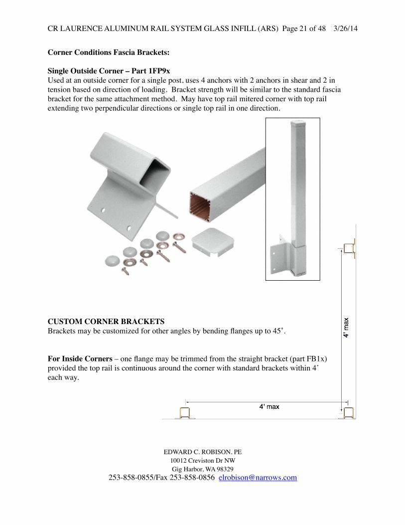
Corner Conditions Fascia Brackets:
Single Outside Corner – Part 1FP9xUsed at an outside corner for a single post, uses 4 anchors with 2 anchors in shear and 2 in tension based on direction of loading. Bracket strength will be similar to the standard fascia bracket for the same attachment method. May have top rail mitered corner with top rail extending two perpendicular directions or single top rail in one direction.
CUSTOM CORNER BRACKETSBrackets may be customized for other angles by bending flanges up to 45˚.
For Inside Corners – one flange may be trimmed from the straight bracket (part FB1x) provided the top rail is continuous around the corner with standard brackets within 4’ each way.
CR LAURENCE ALUMINUM RAIL SYSTEM GLASS INFILL (ARS) Page 21 of 48 3/26/14
EDWARD C. ROBISON, PE10012 Creviston Dr NWGig Harbor, WA 98329
253-858-0855/Fax 253-858-0856 [email protected]

FASCIA MOUNTED POSTCommercial application – Load = 200# or 50 plf any direction on top rail
For 42” rail height and 4’ on center post spacing: P = 200# or 50plf*4 = 200# Mdeck = 42”*200plf = 8,400”# Load from glass infill lites: Wind = 25 psf Mdeck = 3.5’*25psf*42”/2*4’o.c. = 7,350”# DL = 4’*(3 psf*3’+3.5plf)+10# = 60# each post (vertical load)
Typical anchor to wood: 3/8” lag screw. Withdrawal strength of the lags from National Design Specification For Wood Construction (NDS) Table 11.2A.For Doug-Fir Larch or equal, G = 0.50 W = 305 #/in of thread penetration. CD = 1.33 for guardrail live loads, = 1.6 for wind loads. Cm = 1.0 for weather protected supports (lags into wood not subjected to wetting). Tb = WCDCmlm = total withdrawal load in lbs per lag W’= WCDCm =305#/”*1.33*1.0 = 405#/in Lag screw design strength – 3/8” x 5” lag, lm = 5”-2.375”-7/32” = 2.4” Tb = 405*2.4” = 972# Zll = 220# per lag, (horizontal load) NDS Table 11K Z’ll = 220#*1.33*1.0 = 295# ZT = 140# per lag, (vertical load) ZT = 140#*1.33*1.0 = 187#
CR LAURENCE ALUMINUM RAIL SYSTEM GLASS INFILL (ARS) Page 22 of 48 3/26/14
EDWARD C. ROBISON, PE10012 Creviston Dr NWGig Harbor, WA 98329
253-858-0855/Fax 253-858-0856 [email protected]

Anchors to be minimum of 7” center to center and post shall extend 1-1/2” below bottom anchor.
From ∑M about endM = (8.5”*T+1.5”*1.5/8.5*T) = 8.76”TAllowable post moment
Ma=972#*8.76” = 8,515”#For 3/8” lag screw okay for 36” rail height
For 3/8” carriage bolts: Allowable load per bolt = 0.11 in2*20 ksi = 2,200# For bearing on 2” square bearing plate – area = 3.8 in2
Pb = 3.8 in2*1.19*405*1.33 = 2,436# Ma = 2,200#*8.76” = 19,272”# (exceeds post strength)
For vertical load lag capacity is: 2 lags*187# = 374#/post for live load 2 lags#140# = 280# D + L = 200/374+60/280 = 0.75<1.0 okay
For corner posts:
For interior corners there are four lags, two each way. Two lags will act in withdrawal and two will be in shear: Okay be inference from running posts.
For exterior corners – requires either 2 posts (installed within 2” of corner each way) or 1/4”x 4”x8” mounting plate with four 3/8”x4” lag screws and two 3/8” bolts to post.
7.0 0
Tu
Td1.5"
2.5"
CR LAURENCE ALUMINUM RAIL SYSTEM GLASS INFILL (ARS) Page 23 of 48 3/26/14
EDWARD C. ROBISON, PE10012 Creviston Dr NWGig Harbor, WA 98329
253-858-0855/Fax 253-858-0856 [email protected]

STANCHION MOUNT Part PST5: 2”x1-1/2”x 1/8” 304 1/4 Hard Stainless steel tubeEdge distance same as for core mounted posts.Stanchion StrengthFyc = 50 ksi Zyy = 0.543 in3
Reserve strength method from SEI ASCE8-02 section 3.3.1.1 procedure II.where dc/t = (2*2/3) /0.125 = 10.67 < λ1
λ1 = 1.1/√(Fyc/Eo) = 1.1/√(50/28*103) = 26 Mn = 0.543 in3 * 50 ksi = 27,148#”Ms = øMn/1.6 = 0.9*27,148/1.6 = 15,270#”Equivalent post top load42” post heightV = 15,270”#/42” = 363#Post may be attached to stanchion with screws or by grouting.Grout bond strength to stanchion: Asurface √f’c = 7”*4”*√8,000 psi = 2,500# (ignores mechanical bond) for 200# maximum uplift the safety factor against pulling out: SF = 2,500#/200# = 12.5 > 3.0 therefore okay.
Bearing strength on grout: From ∑M about base of stanchion = 0Pu = M+V*D = 2/3D For: M = 10,500”#, V = 250lb, D = 4”Pu = 10,500+250*4 = 4,312# 2/3*4fBmax = Pu*2 = 4,312*2 = 1,691 psi D*1.5”*0.85 4”*1.5”*0.85
For: M = 12,600”#, V = 300lb, D = 4”Pu = 12,600+300*4 = 5,175# 2/3*4fBmax = Pu*2 = 2,029 psi D*1.5”*0.85
Post bearing load on top of stanchion for M = 12,600#”:B = 12,600/6” = 2,100#For 26 ksi allowable bearing pressure, A = 2.1/26 = 0.081”, b = 0.081/1.5” = 0.054”
4" M
IN
4"
6" M
IN CORE POCKET FILL WITH BONSAL ANCHOR CEMENT, NON-SHRINK, NON-METALLIC GROUT
(2) #
10 S
TS S
CR
EW
S
4"
V
M
Pu
Pl
2/3DD
CR LAURENCE ALUMINUM RAIL SYSTEM GLASS INFILL (ARS) Page 24 of 48 3/26/14
EDWARD C. ROBISON, PE10012 Creviston Dr NWGig Harbor, WA 98329
253-858-0855/Fax 253-858-0856 [email protected]

Base Plate Mounted StanchionsPart PST5BPStanchion is welded all around to base plate with 1/8” minimum throat fillet weld capable of developing the full stanchion bending strength.2”x1-1/2”x 1/8” A304 1/4 hard Stainless steel tubeStanchion StrengthZyy = 0.362 in3
Fy = 75 ksi SEI/ASCE 8-02 Table A1Mn = 0.362 in3 * 75 ksi = 27,150#”Service momentMs = ø Mn /1.6Ms = 0.9*27,150”# /1.6 = 15,272#”For Tension zoneCheck compression zone Fc = 50 ksi:n = Es/Ea = 27/10.1 = 2.67Seff = 0.362+(.125”*2.375”*1.187”/2.67)Seff = 0.494Ms = 0.9*0.494*50ksi/1.6 = 13,895”#
Weld to base plate : 1/8” fillet weld all around – develops full wall thickness.Check weld strength SEI/ASCE 8-02 section 5.2.2: transverse loaded fillet weld: øPn = øtLFua, Use Z for tL
Pn = 0.55*0.362*80 ksiPn = 15,928
Ps = 15,928/1.2 = 13,273#”
Base plate bending stress for 3/8” plate S = 5” • 3/82 = 0.117 in3
6Base plate allowable moment Fb = 0.75*50ksi = 37.5 ksi Mall = 37.5 ksi • 0.117 in3 = 4,387 “# → Base plate bending stressTB = CM = 0.84375” • TB • 2
Tall = 4.387 = 2,600#
2 • 0.84375Base plate anchorage is the same as previously calculated for the surface mounted post option for the specific substrate. – Depending on anchorage:Ma ≤ 13,895”# = allowable post moment based on stanchion strength.
27/32" 27/32"M
3 3/4"
CR LAURENCE ALUMINUM RAIL SYSTEM GLASS INFILL (ARS) Page 25 of 48 3/26/14
EDWARD C. ROBISON, PE10012 Creviston Dr NWGig Harbor, WA 98329
253-858-0855/Fax 253-858-0856 [email protected]

CRL 135˚ Post – Corner post
6005-T5 or 6061-T6
Post Section Properties-Area 1.261”Ixx = 1.120 in4
Iyy = 1.742 in4
Sxx = 0.812 in3
Syy = 0.900 in3
rxx = 0.975 inryy = 1.175 inJ = 1.146 ink = 1 for all applications
Allowable bending stress ADM Table 2-21
S1 = LB SC = LB • 0.900 = 0.5√(Iy J) 0.5√(1.120*1.146)=1.58 LB
for LB ≤ 146 = 92” → FCB = 21 ksi 1.58
for LB > 92” FCB= 2.39–0.24(1.58 LB)1/2
Mall = 0.812 • 19ksi = 15,428 #” = 1,286#ft
Connection to base platePost uses standard base plate
Post anchorage methods and strengths are the same as for the square post.
For angles other than 135˚ Use the CRL Adjustable Fastening Plates for Top Rails on either the square or 135˚ posts as needed to achieve the desired angle.
2.12500
2.3 750 0
CR LAURENCE ALUMINUM RAIL SYSTEM GLASS INFILL (ARS) Page 26 of 48 3/26/14
EDWARD C. ROBISON, PE10012 Creviston Dr NWGig Harbor, WA 98329
253-858-0855/Fax 253-858-0856 [email protected]

Series 100 Top RailButts into post
Alloy 6063 – T6 AluminumAllowable StressADM Table 2-24
FT = 15 ksi
FC → 6’ span
2 Lb SC = 2•72” • 0.246 (IyJ) (0.295*1.53)1/2
= 52.7<130 thereforeFc = 15 ksi
Allowable Moments Horiz.= 0.295in3 15 ksi = 4,425#” =
368.75 #’ Vertical load = 0.246in3 15 ksi = 3,690#” = 307.5 #’
Maximum allowable load for 72” o.c. post spacing - vertical W = 3,690”#*8/(69.625”2) = 6.09 pli = 73.1 plf
P = 3,690”#*4/69.625” = 212#
Maximum span without load sharing, P = 200# - vertical S = 3,690”#*4/200# = 73.8” clear Max post spacing =73.8”+2.375” = 76.175”
For horizontal loading rail strength is greater and therefore okay by inference.
Maximum allowable load for 72” length horizontal load W = 4,425”#*8/722 = 6.8 pli = 81.9 plf
P = 4,425”#*4/72” = 245.8#
Maximum span for P = 200# and W = 50 plf horizontal load W = √(368.75#’*8/50) = 7.68’ = 7’ 8.5”
P = 368.75#’*4/200 = 7.375’ = 7’3.5” controls
CR LAURENCE ALUMINUM RAIL SYSTEM GLASS INFILL (ARS) Page 27 of 48 3/26/14
EDWARD C. ROBISON, PE10012 Creviston Dr NWGig Harbor, WA 98329
253-858-0855/Fax 253-858-0856 [email protected]

SERIES 100 BOTTOM RAIL Rail Properties:6063-T6 AluminumIxx = 0.102 in4, Sxx = 0.101 in3Iyy = 0.164 in4, Syy = 0.193 in3rxx = 0.476”, ryy = 0.603” For 72” on center posts; L = 72”-2.375”-1”x2 = 67.625” ; Lb = 1/2L = 33.81”Lb/ry = 33.81”/0.603 = 56 From ADM Table 2-24Fbc = 16.7-0.073 56 = 12.6 ksi
Allowable Moments Horiz.= 0.193in3 12.6 ksi =2,432”#Maximum allowable load for 72” o.c. post spacing W = 2,432”#*8/(67.625”2) = 4.25 pli = 51 plf P = 2,432”#*4/67.625” = 144#Max span for 50 plf load = (8*2,432/(50/12))1/2 = 68.33” clear span Rail fasteners -Bottom rail connection block to post #101.5” 55 PHP SMS Screw
Check shear @ post (6005-T5)
2x Fupostx dia screw x Post thickness x SF
V= 238 ksi 0.1697” 0.10” 1 = 3 (FS)
V = 430#/screw Since minimum of 2 screws used for eachAllowable load = 2 430# = 860#
Rail Connection to RCB
2 screws each end #8 Tek screw to 6063-T6V= 238 ksi 0.1309” 0.07” 1 = 232# 3 (FS)
CR LAURENCE ALUMINUM RAIL SYSTEM GLASS INFILL (ARS) Page 28 of 48 3/26/14
EDWARD C. ROBISON, PE10012 Creviston Dr NWGig Harbor, WA 98329
253-858-0855/Fax 253-858-0856 [email protected]

Intermediate post used to provide additional support to bottom rail.1.4” square 0.1” wall thicknessActs in compression only.Secured to rail with two #8 tek screwsShear strength of screws:
Top rail connection to post face:Use RCB attached to post with 2 #10 screws same as bottom rail.
V= 238 ksi 0.1697” 0.10” 1 = 430#/screw 3 (FS)
Since minimum of 2 screws used for eachAllowable load =2 430# = 860#
The connection block can be cut square for use in horizontal rail applications or angled for use in sloped applications such as along stairs or ramps.
Connection of rail to RCB is with (2) #8 Tek screw to 6063-T6
V= 238 ksi 0.1309” 0.07” 1 = 232# 3 (FS)
Vtot = 2*232# = 464#
CAP RAIL100SERIES
POST CAP
ANGLED ATTACHMENTBRACKET CUT FORRAIL CONNECTING(RCB)
POSTBOTTOM2 3/8" SQ.
CR LAURENCE ALUMINUM RAIL SYSTEM GLASS INFILL (ARS) Page 29 of 48 3/26/14
EDWARD C. ROBISON, PE10012 Creviston Dr NWGig Harbor, WA 98329
253-858-0855/Fax 253-858-0856 [email protected]

Intermediate post fittingUsed for intermediate posts along stairwaysFitting locks into top of post using structural silicone.
Maximum load on fitting is 300#6’ post spacing * 50 plf = 300#
Shear resisted by direct bearing between fitting and post area = 2.175”*0.1875 = 0.408 in2
Bearing pressure = 300#/.408 = 736 psi
Moment of fitting to post: This is an intermediate post with rotation of top rail restrained at rail ends. Moment of fitting is created by eccentricity between bottom of top rail and top of post: e = 0.425” M = 300# * (0.425”) = 127.5#”Moment on fitting is resisted by tearing in siliconeSilicone tear strength: From Dow Corning, (silicone manufacturer), CRL 95C Silicone is the same product as the Dow Corning 995 Silicone Structural Glazing Sealant, from Dow Corning product information sheet Tear strength ≥ 49 ppi Peel strength ≥ 40 ppi Ult. tension adhesion ≥ 170 psi Tensile strength ≥ 48 psi @ 25% elongation Tensile strength ≥ 75 psi @ 50% elongation
Moment capacity:49*2.1752+ (49)/2 psi *2.175”2 = 348#”
SF = 348#”/127.5#” = 2.73 > 2.0 okay
Option #8 Tek screws: Shear strength = V= 238 ksi 0.1309” 0.07” 1 = 232# 3 (FS)Added moment capacity = 232#*2.375” = 551#”
CAP RAIL
POSTINTERMEDIATE2 3/8" SQ.
ADAPTORSTAIR POSTINTERMEDIATE
OPTIONAL #8 TEK SCREW
OPTIONAL #8 TEK SCREW
SILICONEADHESIVEALL AROUND
SILICONEADHESIVEALL AROUND
CR LAURENCE ALUMINUM RAIL SYSTEM GLASS INFILL (ARS) Page 30 of 48 3/26/14
EDWARD C. ROBISON, PE10012 Creviston Dr NWGig Harbor, WA 98329
253-858-0855/Fax 253-858-0856 [email protected]

Series 200 Top rail
Area: 0.887 sq in
Ixx: 0.254 in4
Iyy: 1.529 in4
rxx: 0.536 inryy: 1.313 inCxx: 1.194 inCyy: 1.750 inSxx: 0.213 in3 bottomSxx: 0.457 in3 topSyy: 0.874 in3
6063-T6 Aluminum alloyFor 72” on center posts; L = 72”-2.375”-1”x2 = 67.625” ; kLb = 1/2L = 33.81”Fbc = 16.7-0.073 33.81 = 14.82 ksi From ADM Table 2-24 1.313Ft = 15 ksiAllowable Moments Horiz.= 0.874in3 14.82 ksi = 12,953#” = 1,079#’ Vertical load = 0.457in3 14.82 ksi = 6,773#” top compression or = 0.213in3 15 ksi = 3,195#” controls vertical- bottom tension
Maximum allowable load for 72” o.c. post spacing - vertical W = 3,195”#*8/(67.625”2) = 5.59 pli = 67 plf P = 3,195”#*4/67.625” = 189# Load sharing with bottom rail required for 6 foot post spacing. Spreader bar at mid span (3’ maximum spacing) will subdivide top rail and provide required additional support.
Maximum span without load sharing, P = 200# S = 3,195#”*4/200# = 63.9” clear Max post spacing =63.9”+2.375” = 66-1/4”, 5’ 6-1/4”
For horizontal load, maximum span for 50 plf load L = (8Ma/50plf)1/2 = (8*1,079/50plf)1/2 = 13.14’for 200# concentrated load L = (4M/200#) = (4*1,079/200plf)= 21.58’
deflection limits will control.
CR LAURENCE ALUMINUM RAIL SYSTEM GLASS INFILL (ARS) Page 31 of 48 3/26/14
EDWARD C. ROBISON, PE10012 Creviston Dr NWGig Harbor, WA 98329
253-858-0855/Fax 253-858-0856 [email protected]

Series 300 Top Rail
Area: 0.881 sq inPerim: 21.29 inIxx: 0.603 in4
Iyy: 1.149 in4
Kxx: 0.828 inKyy: 1.142 inCxx: 1.599 inCyy: 1.501 inSxx: 0.377 in3
Syy: 0.766 in3
Allowable stresses ADM Table 2-21
FCb → L/ ry = (72 – 2 3/8” – 2.1”) = 59.1 1.142Based on 72” max post spacingFCb = 23.9 – 0.124(59.1) = 16.57 ksiMall horiz = 16.57ksi • (0.766) = 12,694”# Vertical loads shared with bottom railFor vertical load → bottom in tension top comp. Fb = 19 ksi Mall vert = (0.377in4) • 19 ksi = 7.163”# Allowable loads
Horizontal → uniform → W= 12,694 • 8 = 19.6 #/in = W = 235 plf 722 PH = 4 • 12,694 = 705 # 72Vertical → W = 7,163 • 8 = 11.05 #/in = 132.6 plf (Top rail alone) 722 P = 7,163 • 4 = 398 # 72
Rail to post connection: Direct bearing for downward forces and horizontal forces:For uplift connected by (2) #10 Tek screws each post:2x Fupostx dia screw x Post thickness / SF (ADM 5.4.3)V= 2*30 ksi *0.1379” *0.09” * 1 = 325#/screw
3 (FS)
3.00
2.88
2.482
CR LAURENCE ALUMINUM RAIL SYSTEM GLASS INFILL (ARS) Page 32 of 48 3/26/14
EDWARD C. ROBISON, PE10012 Creviston Dr NWGig Harbor, WA 98329
253-858-0855/Fax 253-858-0856 [email protected]

Top Rail Infill for Glass Iyy = 0.156 in4 Ixx = 0.023 in4 Syy = 0.125 in3 Sxx = 0.049 in4
Insert compression locks into top railHorizontal forces transferred between insert and top rail by direct bearing on locking tabs.
Bearing area = 1/8” widthAllowable bearing load will be controlled by spreading of top railCheck significance of circumferential stress: R/t = 3”/0.09375 = 32 > 5 therefore can assume plane bending and error will be minimal M = 2.08”*W Mall = S*Fb Fb = 20 ksi for flat element bending in own plane, ADM Table 2-24 S = 12”/ft*(0.094)2/6 = 0.0177 in3
Wall = Mall/2.08” = (S* Fb)/2.08” = (0.0177 in3*20 ksi)/2.08” = 170 plf
For 36” panel height – 1/2 will be tributary to top rail: Maximum live load = 170 plf/(3’/2) = 113 psf.
Check deflection: ∆ = WL3/(3EI) I = 12”*0.093753/12 = .000824 in4
∆ = 170plf*2.08”3/(3*10.1x106*.000824) = 0.06”
The required deflection to cause the infill to disengage: 0.05” Reduce allowable load to limit total deflection:
0.05/0.06*113 plf = 94 plf
INFILL LOADRESTRAINEDAT POSTS
Mi
CR LAURENCE ALUMINUM RAIL SYSTEM GLASS INFILL (ARS) Page 33 of 48 3/26/14
EDWARD C. ROBISON, PE10012 Creviston Dr NWGig Harbor, WA 98329
253-858-0855/Fax 253-858-0856 [email protected]

Adjustable Fastening Plates for Top RailsTop rail connection to post:
For Vertical loads top rail is restrained by (2) #10 tek screws each side.Connection of bracket to post is with (2) #14 screws so is stronger.
For horizontal loads the top rail directly bears on side of post.
Tek screw strength: Check shear @ rail (6063-T6)2x Furailx dia screw x Rail thickness x SFV= 230 ksi 0.1379” 0.09” 1 = 325#/screw
Since minimum of 2 screws used for eachAllowable load = 2 325# = 650#
Post bearing strength Vall = Abearing*FB Abearing = 0.09”*2.25” = 0.2025 in2
FB = 21 ksi Vall = 0.2025 in2 * 21 ksi = 4.25 k
Bracket tab bending strengthVertical uplift forceFor 6061T6 aluminum stamping 1/8” thickFb = 28 ksi – ADM Table 2-21S = 0.438”*(.125)3/12 = 0.00007 in3
Ma = 28 ksi*0.00007 = 196”#Pa = Ma/l = 196”#/1.158” = 169#Uplift limited by bracket strength: Upall = 2*169 = 338# per bracket
1.158
0.438
CR LAURENCE ALUMINUM RAIL SYSTEM GLASS INFILL (ARS) Page 34 of 48 3/26/14
EDWARD C. ROBISON, PE10012 Creviston Dr NWGig Harbor, WA 98329
253-858-0855/Fax 253-858-0856 [email protected]
3 (FS)

RAIL SPLICES:
Splice plate strength:Vertical load will be direct bearing from rail/plate to post no bending or shear in plate.
Horizontal load will be transferred by shear in the fasteners:
Rail to splice plates:
Tek screw strength: Check shear @ rail (6063-T6)2x Furailx dia screw x rail thickness x SFV= 230 ksi 0.1379” 0.09” 1 = 325#/screw; for two screws = 650#
or Furplatex dia screw x plate thickness x SFV= 38 ksi 0.1379” 0.125” 1 = 218#/screw; for two screws = 436#
3 (FS)Post to splice plate:Screws into post screw chase so screw to post connection will not control.splice plate screw shear strength2x Fuplatex dia screw x plate thickness x SFV= 238 ksi 0.1379” 0.125” 1 = 416#/screw; for two screws = 832#
3 (FS)Check moment from horizontal load:M = P*0.75”. For 200# maximum load from a single rail on to splice platesM = 0.75*200 = 150#”S = 0.125*(0.625)2/6 = 0.008 in3fb = 150#”/(0.008*2) = 9,216 psi
For corner brackets screw strength and bending strength will be the same.
CR LAURENCE ALUMINUM RAIL SYSTEM GLASS INFILL (ARS) Page 35 of 48 3/26/14
EDWARD C. ROBISON, PE10012 Creviston Dr NWGig Harbor, WA 98329
253-858-0855/Fax 253-858-0856 [email protected]
3 (FS)

Series 350 Top Rail
Area: 0.725 in2
Perim: 21.338 in
Ixx: 0.263 in4
Iyy: 1.398 in4
rxx: 0.602 inryy: 1.389 in
Cxx: 1.128 inCyy: 1.875 inSxx: 0.233 in3
Syy: 0.737 in3
Allowable stresses ADM Table 2-24 6063-T6 Aluminum
FCb → Rb/t = 1.875” = 15 line 16.1 0.125
Based on 72” max post spacingFCb = 18.5 – 0.593(15)1/2 = 16.20 ksiMall horiz = 16.20ksi • (0.737) = 11,942”# Vertical loads shared with bottom railFor vertical load → bottom in tension top comp. Fb = 18 ksiFor top rail acting alone Mall vert = (0.233in3) • 18 ksi = 4,194”# or Controls =(0.263in4/0.997”)*16.20 ksi = 4,273”#
Allowable loads For 6’ post spacing:Horizontal → uniform → WH= 11,942•8 = 18.4 #/in = WH = 221.1 plf 722 PH = 4 • 11,942 = 663.4 # 72Vertical → W = 4,194 • 8 = 6.5 #/in = 78 plf (Top rail alone) 722 P = 4,194 • 4 = 233 #
72
CR LAURENCE ALUMINUM RAIL SYSTEM GLASS INFILL (ARS) Page 36 of 48 3/26/14
EDWARD C. ROBISON, PE10012 Creviston Dr NWGig Harbor, WA 98329
253-858-0855/Fax 253-858-0856 [email protected]

Series 400 Top rail
Ixx: 0.611 in4
Iyy: 3.736 in4
rxx: 0.717 inryy: 1.774 inCxx: 1.358 inCyy: 2.50 inSxx: 0.450 in3 bottomSxx: 0.399 in3 topSyy: 1.494 in3
6063-T6 Aluminum alloyFor 72” on center posts; L = 72”-2.375”-1”x2 = 67.625” ; kLb = 1/2L = 33.81”Fbc = 16.7-0.073 33.81 = 15.3 ksi From ADM Table 2-24 1.774Ft = 15 ksiAllowable Moments Horiz.= 1.494 in3 15.0 ksi =22,410”# = 1867.5#’ Vertical load = 0.399in3 15 ksi = 5,985”# = 498.75#’ Maximum allowable load for 72” o.c. post spacing - vertical W = 5,985”#*8/(67.625”2) = 10.47 pli = 125.6 plf P = 5,985”#*4/67.625” = 354#
Maximum span without load sharing, P = 200# S = 5,985”#*4/200# = 119.7” clear, L = (8Ma/50plf)1/2 = (8*498.75/50plf)1/2 = 8.93’ Max post spacing =8’ 11”+2.375” = 9’ 1-3/8”
For horizontal load, maximum span for 50 plf load L = (8Ma/50plf)1/2 = (8*1,867.5/50plf)1/2 = 17.29’
1/2"
2 1/4"
2 5/8"
5"
CR LAURENCE ALUMINUM RAIL SYSTEM GLASS INFILL (ARS) Page 37 of 48 3/26/14
EDWARD C. ROBISON, PE10012 Creviston Dr NWGig Harbor, WA 98329
253-858-0855/Fax 253-858-0856 [email protected]

MID RAIL
Ixx = 0.123 in4
Iyy = 0.177 in4
Sxx = 0.115 in3
Syy = 0.209 in3
rxx = 0.579 inryy = 0.695 in
Allowable stresses ADM Table 2-24 6063-T6 AluminumFt = 19 ksi For vertical loadsFCb → Rb/t = 1.25” = 0.33 line 16.1 FCb = 18 ksi 3.75Mall vert = 18ksi • (0.115) = 2,070”#
For horizontal loads:Ft = 15 ksi For vertical loadsFCb → Lb/ry = 35” = 50.4 line 11 0.695Based on 72” max post spacingFCb = (16.7-0.073*50.4) ksi = 13.0 ksiMall horiz = 13ksi • (0.209) = 2,717”#
For intermediate rail acting aloneAllowable loads
Horizontal → uniform → WH= 2,717•8 = 4.44 #/in = WH = 53 plf 702 PH = 4 • 2,717 = 155 # Not used for top rail 50# conc load appl. 70Vertical → W = 2070 • 8 = 3.38 #/in = 40.6 plf (Top rail alone) 702 P = 2070 • 4 = 118# Not used for top rail 50# conc load appl. 70Maximum wind load for 3’6” lite height, 1’9” tributary widthWmax = 53/1.75 = 30.3 plf
Filler for glass infill inserts into bottom of rail to glaze glass lights. May be used with either Mid Rail or standard bottom rail.
1.6875
1.75
t =0.062
CR LAURENCE ALUMINUM RAIL SYSTEM GLASS INFILL (ARS) Page 38 of 48 3/26/14
EDWARD C. ROBISON, PE10012 Creviston Dr NWGig Harbor, WA 98329
253-858-0855/Fax 253-858-0856 [email protected]

Glass Infill Bottom Rail
For 72” on center posts; L = 72”-2.375”-1”x2 = 67.625” ; Lb = 1/2L = 33.81”Lb/ry = 33.81”/0.662 = 51.07 From ADM Table 2-24Fbc = 16.7-0.073 51.07 = 12.97 ksi
Allowable Moments Horiz.= 0.204in3 12.97 ksi =2,646”#Maximum allowable load for 72” o.c. post spacing W = 2,646”#*8/(67.625”2) = 4.63 pli = 55.5 plf P = 2,646”#*4/67.625” = 156.5#Max span for 50 plf load = (8*2646/(50/12))1/2 = 71.28” clear span Rail fasteners -Bottom rail connection block to post #10x1.5” 55 PHP SMS Screw
Check shear @ post (6005-T5)2x Fupostx dia screw x Post thickness x SFV= 238 ksi 0.1697” 0.10” 1 =
3 (FS)V = 430#/screw Since minimum of 2 screws used for eachAllowable load = 2 430# = 860#
Rail Connection to RCB
2 screws each en #8 Tek screw to 6063-T6
2*30ksi0.1309”0.07” 1 = 232#/screw 3Allowable tension = 2*232 = 464#
OK
Area: 0.3923 sq inPerim: 11.648 in
Ixx: 0.0869 in^4Iyy: 0.172 in^4Kxx: 0.472 inKyy: 0.662 inCxx: 1.0133 inCyy: 0.8435 inSxx: 0.0857 in^3 BottomSxx: 0.129 in^3 TopSyy: 0.204 in^3
CR LAURENCE ALUMINUM RAIL SYSTEM GLASS INFILL (ARS) Page 39 of 48 3/26/14
EDWARD C. ROBISON, PE10012 Creviston Dr NWGig Harbor, WA 98329
253-858-0855/Fax 253-858-0856 [email protected]

WIND SCREEN MID RAILStandard bottom rail with infill Refer to bottom rail calculations for rail properties.
Check bottom rail strength for span used in privacy screen.
Midrail glass infill when installed in rail will stiffen the flanges (legs) continuously so that the flanges are equivalent to flat elements supported on both edges:From ADM Table 2-24 section 16.b/t = 1.1”/0.07 = 15.7 < 23Therefore Fca = 15 ksi
Strength of infill piece: Ixx: 0.0162in4
Iyy: 0.0378 in4
Sxx: 0.0422 in3
Syy: 0.0490 in3
Fca = 15 ksi
When inserted into bottom rail determine the effective strength:ratio of load carried by infill: Iyy infill/ Iyy rail = 0.0378/0.172 = 0.22 Syy infill ≤ 0.22*0.204 = .045 < 0.049
Allowable Moments Horiz.= (0.204in3 +0.045) *15 ksi = 3,735”#Maximum allowable load for 70” screen width L = 70”-1”*2-2.375*2 = 63.25” W = 3,735”#*8/(63.25”2) = 7.5 pli = 90 plf P = 3,735”#*4/63.25” = 236#
Maximum allowable load for 60” screen width L = 60”-1”*2-2.375*2 = 53.25” W = 3,735”#*8/(53.25”2) = 10.5 pli = 126 plf P = 3,735”#*4/53.25” = 280#
CR LAURENCE ALUMINUM RAIL SYSTEM GLASS INFILL (ARS) Page 40 of 48 3/26/14
EDWARD C. ROBISON, PE10012 Creviston Dr NWGig Harbor, WA 98329
253-858-0855/Fax 253-858-0856 [email protected]

STANDARD POST RAIL CONNECTION BLOCK
Can be used to connect top rails to standard or 4”x4” post face, walls or other end butt connection.
Top rail snaps over block and is secured with either silicone adhesive or #8 tek screws.
Connection strength to post or wall: (2) #10x1.5” 55 PHP SMS Screw
Check shear @ post (6005-T5) Fupostx dia screw x Post thickness x SFEq 5.4.3-2V= 38 ksi 0.19” 0.1” 1 = 240#/screw for standard post
3 (FS)Since minimum of 2 screws used for each, Allowable load = 2 240# = 480#
For 4”x4” post:V= 38 ksi 0.19” 0.15” 1 = 360#/screw for standard post
3 (FS)Since minimum of 2 screws used for each, Allowable load = 2 360# = 720#
Connections to walls and other surfaces is dependant on supporting material.Alternative fasteners may be used for connections to steel, concrete or wood.
CR LAURENCE ALUMINUM RAIL SYSTEM GLASS INFILL (ARS) Page 41 of 48 3/26/14
EDWARD C. ROBISON, PE10012 Creviston Dr NWGig Harbor, WA 98329
253-858-0855/Fax 253-858-0856 [email protected]

WALL MOUNT END CAPS
End cap is fastened to the top rail with 2) #10x1” 55 PHP SMS Screws
2x Fupostx dia screw x Cap thickness x SFEq 5.4.3-2V= 2*38 ksi 0.19” 0.15” 1 = 3 (FS)722#/screw , 1,422# per connection
Connection to wall shall use either:
#14x1-1/2” wood screw to wood, minimum 1” penetration into solid wood.
Allowable load = 2*175# = 350#Wood shall have a G ≥ 0.43From ADM Table 11M
For connection to steel studs or sheet metal blockingUse #12 self drilling screws.Minimum metal thickness is 18 gauge, 43 mil (0.0451”)Allowable load = 280#/screw
CR LAURENCE ALUMINUM RAIL SYSTEM GLASS INFILL (ARS) Page 42 of 48 3/26/14
EDWARD C. ROBISON, PE10012 Creviston Dr NWGig Harbor, WA 98329
253-858-0855/Fax 253-858-0856 [email protected]

Wall Mounted End Caps
For connection to masonry or concrete use 3/16 screw-in anchor
300 and 350 Series end caps use same fasteners and have identical strengths
CR LAURENCE ALUMINUM RAIL SYSTEM GLASS INFILL (ARS) Page 43 of 48 3/26/14
EDWARD C. ROBISON, PE10012 Creviston Dr NWGig Harbor, WA 98329
253-858-0855/Fax 253-858-0856 [email protected]

CRL Standard 4”x4” Square Post Strength 6005-T5 or 6061-T6 Post-Area 2.65 in2
Ixx = Iyy = 6.55 in4
Sxx = Syy = 3.27 in3
r = 2.38 inJ = 31.1 ink = 1 for all applications
Allowable bending stress ADM Table 2-21
S1 = LB SC = LB • 3.27 = 0.5√(Iy J) 0.5 √(6.55 • 31.1)
= 0.458 LB
for LB ≤ 146 = 318.8” → FCB = 21 ksi 0.458
for LB > 318.8” FCB= 2.39– 0.24(0.458 LB)1/2
Mall = 3.27 in3 • 19ksi = 62,130#” = 5,177#ft
4 .00
4.00
. 375"
Cb
Tb
VM
Cp Ts
5" .75".75"
4"1.5" 1.5"
3.75" 1.25"
E
CR LAURENCE ALUMINUM RAIL SYSTEM GLASS INFILL (ARS) Page 44 of 48 3/26/14
EDWARD C. ROBISON, PE10012 Creviston Dr NWGig Harbor, WA 98329
253-858-0855/Fax 253-858-0856 [email protected]

6-1/2” Square Base Plates for4” Square PostsConnection to base plate
Failure modes → screw tension → screw shear → screw withdrawal
For screw withdrawalSee ADM 5.4
W = 2.3 • e • d • π • Fsy
e = full thread engagement = 1”d = max root diameter = 0.248” minor = 0.185”Base plate to post screws are AISI 4037 steel alloy fabricated in accordance with SAE J429 Grade 8 and coated with Magni 550 corrosion protection. Fsy = 20 ksi
W = 2/3 • 1” • 0.248” • π • 20ksi
W = 10.39k
W’ = 10.39 = 3.46k
4.0 Safety factor
Screw tension → Ty = 0.0483 in2 • 110 ksi = 5314 # Vu = 0.0483* 45ksi =2,174#
FtU = 0.0376 • 150 ksi = 5640#
Safety factors for screws calculated from SEI/ASCE 8-02 Section 5 LRFD factorsFor yielding SF = 1.6/0.75 = 2.13 → 5,314#/2.13 = 2,495#
For fracture SF = 1.6/(0.9*0.75) = 2.37 → 5,640/2.37 =2,380#
Shear strengthSF = 1.6/0.65 = 2.46 Va=Vu/SF =2,174#/2.46= 884#
Base plate bending stress Ft = 24 ksi → Smin = 6.5” • 3/82 = 0.152 in3
6
CR LAURENCE ALUMINUM RAIL SYSTEM GLASS INFILL (ARS) Page 45 of 48 3/26/14
EDWARD C. ROBISON, PE10012 Creviston Dr NWGig Harbor, WA 98329
253-858-0855/Fax 253-858-0856 [email protected]
Major root area
average root area

6-1/2” Square Base Plates Cont.
Base plate allowable moment Mall = 24 ksi • 0.152 in3 = 3,648 “# → Base plate bending stressTB = CM = 5/8” • TB • 2 = 3,648#”
Tall = 3,648#” = 2,918#
2 • 0.625
Maximum allowable post moment for base plate strengthMall = 2 • 2,918 • 5.75” = 33,562#“
Limiting factor = screws to postMult = 2 • 5,314# • 3.69” = 39,217#” Mall = 2 • 2,380# • 3.69” = 17,264#”
For factors of safety refer to Aluminum Design Manual Section 5.3.2.1and SEI/ASCE 8-02 section 5
BASE PLATE ANCHORAGETypical design Moment 6’*50 plf*42” = 12,600#”TDes = 12,600 = 1,096#
2 • 5.75”
Typical base plate anchorage design for 1,100# tension
For 200# top load and 42” post htT200 = 8,400 = 960# 2*4.375”
For 42” post height the maximum live load at the top of the post is:Pmax = 17,264”#/42” = 411#
For 50 plf live load maximum post spacing is:Smax = 411#/50 plf = 8.22’ = 8’2.5”
Base plate anchors are the same as for the 5” square base plates – Allowable moment on plate for each anchor type is 5.75”/4.375 = 1.314M4x4 = Ms*1.314 ≤ 17,264”#
CR LAURENCE ALUMINUM RAIL SYSTEM GLASS INFILL (ARS) Page 46 of 48 3/26/14
EDWARD C. ROBISON, PE10012 Creviston Dr NWGig Harbor, WA 98329
253-858-0855/Fax 253-858-0856 [email protected]

4x4 Post System StrengthFor installation to steel or concrete:Ma = 17,264”#For standard 42” rail height maximum post spacing:S = 17,264/(42”*50plf) = 8.22’
For connections to wood decks:For 50plf top load and 42” post height: Required embed depth:For protected installations the minimum embedment is:le = 1,114#/323#/in = 3.45” : +7/32” for tip = 3.67” 4.5” minimum lag length.
For weather exposed installations the minimum embedment is:le = 1,114#/243#/in = 4.58” : +7/32” for tip = 4.80”
For weather exposed installations use 6” lag screws and increase blocking to 5.5” minimum thickness.a = 2*1,114/(1.33*625psi*6.5”)= 0.412”M = 1,114#*2 lags*(5.75”-0.412/2) = 12,352”#
Maximum post spacing for 50 plf top load and 42” rail height:S = 12,352”#/(42*50) = 5.88’
For 3/8” carriage bolts to wood with minimum 4” nominal lumber framing and 2” square washers: Carriage bolts will develop the full allowable strength of the base plate so allowable post spacing is the same as for the attachment to steel or concrete.
Other components for 4x4 posts:
Rail Connecting Blocks – Same strength as previously calculated used to attach all rails including top rails.
All rail types may be used as simple spans between posts with the same strengths and allowable spans as calculated for the applicable rail.
CR LAURENCE ALUMINUM RAIL SYSTEM GLASS INFILL (ARS) Page 47 of 48 3/26/14
EDWARD C. ROBISON, PE10012 Creviston Dr NWGig Harbor, WA 98329
253-858-0855/Fax 253-858-0856 [email protected]

Excerpts from National Design Specifications
CR LAURENCE ALUMINUM RAIL SYSTEM GLASS INFILL (ARS) Page 48 of 48 3/26/14
EDWARD C. ROBISON, PE10012 Creviston Dr NWGig Harbor, WA 98329
253-858-0855/Fax 253-858-0856 [email protected]