CQ_Bonanza_Plan_Package.pdf - 0201.nccdn.net additional artwork is from a redesigned Cleveland...
16
Cleveland “Quickie” Bonanza This plan package is not a 100% copy of the original kit. As you make your way through the instructions you will see the differences. Here’s just a few of them: The paint scheme on the original was too psychedelic for my taste so I gave the model a more modern look. The V-Tail is printed on both sides. The original kit used 1/16” balsa. This plan package uses 1/32” balsa. Certain formers such as the fuselage formers are created by bonding two duplicate formers together. These duplicate formers are laid out in a cross-grain fashion to provide maximum strength when bonded together. Use spray glue such as 3M Super 700 available at most hardware stores. Instructions for a removable nose piece are included. 1/8” Tan II rubber i s recommended for the motor but any size can be used based on the builder’s desire. The wing is two-piece instead of one-piece like the original. They attach to the sides of the fuselage. Ribs are provided to produce a small airfoil unlike the original wing which is flat. The original kit had landing gear mounted in the fuselage like a taildragger. I redesigned this version with the correct tricycle configuration. Many pieces are slightly oversized to allow for custom fits. The original instructions were very vague. In this plan package they are broken down step-by- step. The complete original instructions are located at the end and include basic tips on how to fly the model. I hope you enjoy it. If you find any errors with the plan package I would greatly appreciate knowing about them. Please contact me at [email protected]
Transcript of CQ_Bonanza_Plan_Package.pdf - 0201.nccdn.net additional artwork is from a redesigned Cleveland...
Cleveland “Quickie” Bonanza This plan package is not a 100% copy of the original kit. As you make your way through the instructions you will see the differences. Here’s just a few of them:
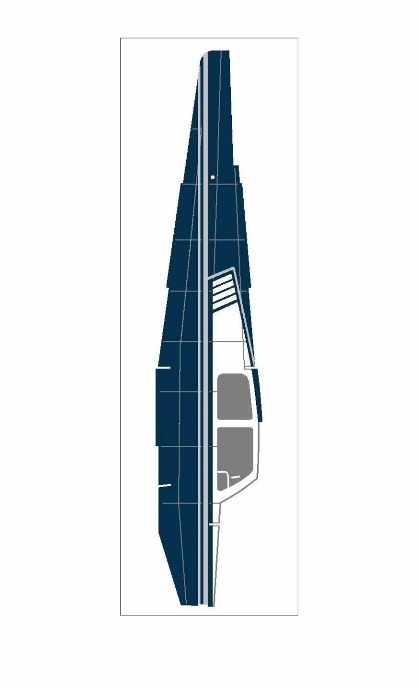
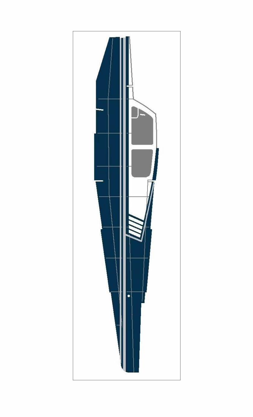
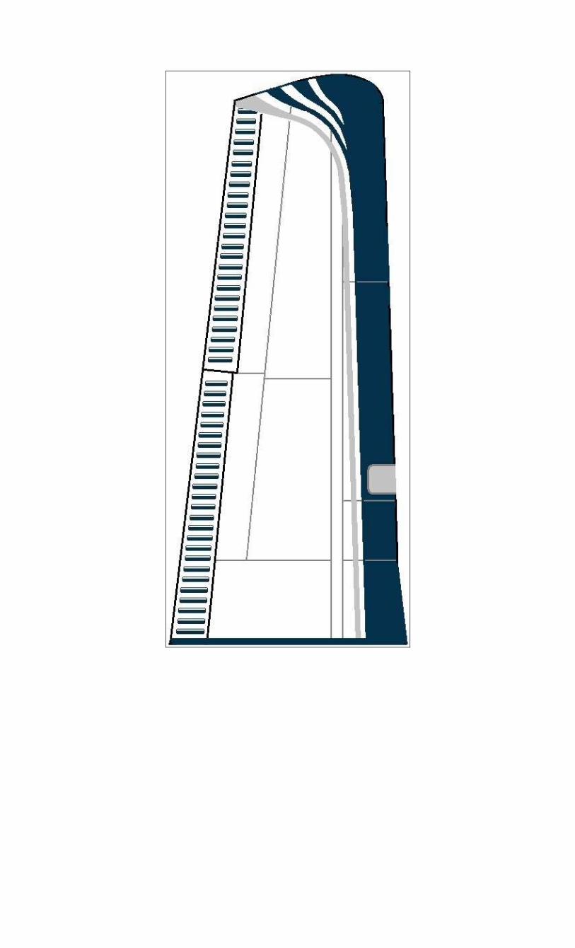
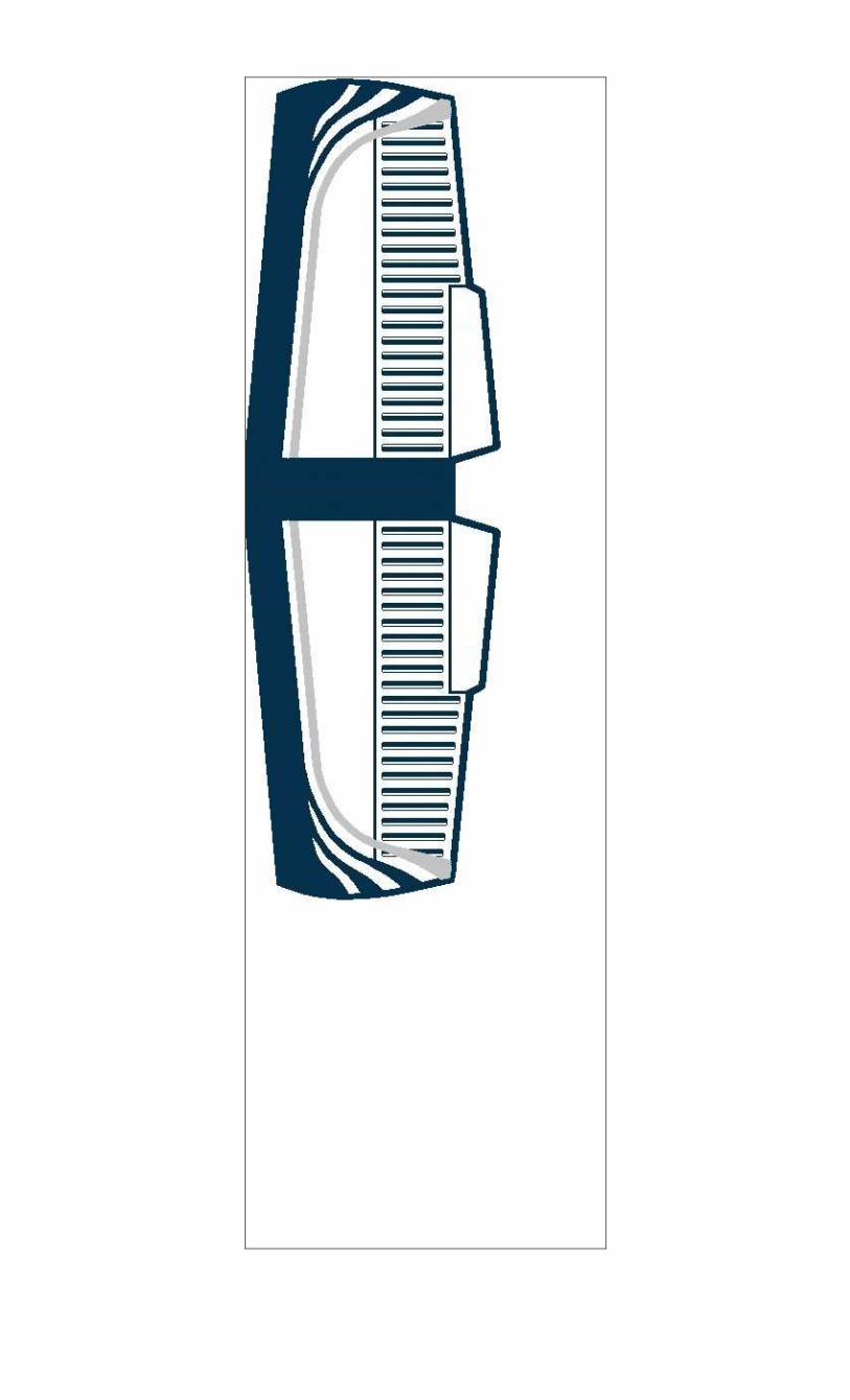
The paint scheme on the original was too psychedelic for my taste so I gave the model a more modern look. The V-Tail is printed on both sides.
The original kit used 1/16” balsa. This plan package uses 1/32” balsa. Certain formers such as the fuselage formers are created by bonding two duplicate formers together. These duplicate formers are laid out in a cross-grain fashion to provide maximum strength when bonded together. Use spray glue such as 3M Super 700 available at most hardware stores.
Instructions for a removable nose piece are included. 1/8” Tan II rubber is recommended for the motor but any size can be used based on the builder’s desire.
The wing is two-piece instead of one-piece like the original. They attach to the sides of the fuselage. Ribs are provided to produce a small airfoil unlike the original wing which is flat.
The original kit had landing gear mounted in the fuselage like a taildragger. I redesigned this version with the correct tricycle configuration.
Many pieces are slightly oversized to allow for custom fits.
The original instructions were very vague. In this plan package they are broken down step-by-step.
The complete original instructions are located at the end and include basic tips on how to fly the model. I hope you enjoy it. If you find any errors with the plan package I would greatly appreciate knowing about them. Please contact me at [email protected]

Cleveland “Quickie” Bonanza
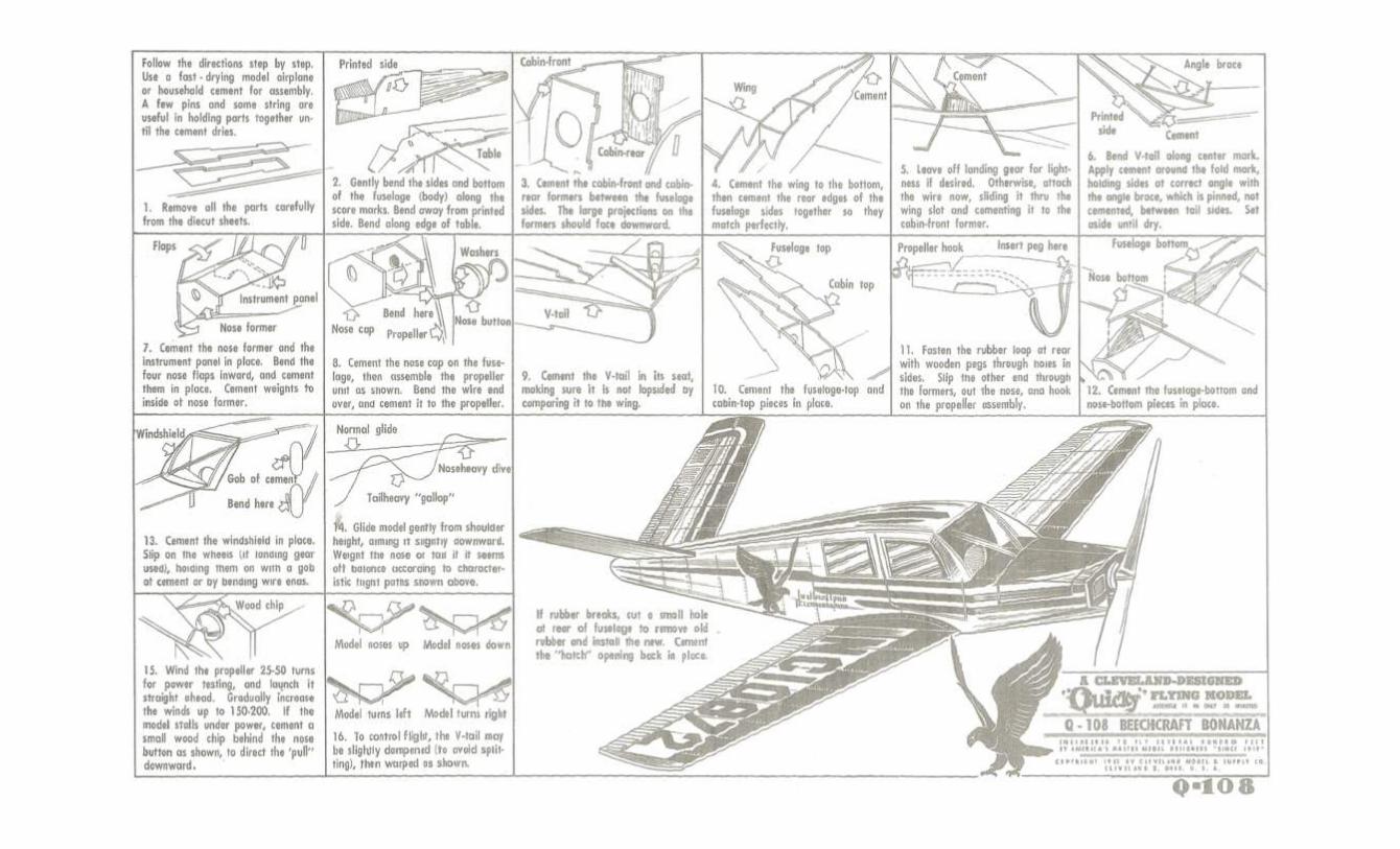
The original step-by-step instructions are presented here with notes about optional assembly procedures. The additional artwork is from a redesigned Cleveland Quickie Luscombe Sedan kit drawn by Paul Bradley of Parmodels.com. Visit his website to see some great plans for other kits.
This plan package is not die-cut like the original kit. It is highly recommended that a sharp Xacto® blade be used at all times. Don’t skimp on this or you will tear the wood when cutting it out. Off-brand blades are not as good as the Xacto® brand. When the blade starts to drag, change it out for a new one. It is also best to NOT cut on the lines. Cut the pieces out oversized and sand down to the line. This is especially important when cutting out notches.
I prefer to use Loctite® brand Super Glue. Again, don’t skimp on the brand name. Off-brand cements are inconsistent.
This step was necessary because the original kit used 1/16” balsa. Since this plan package uses 1/32” balsa, DON’T try to bend the sides prior to assembly. The 1/32” balsa will form to the contour just fine.

When gluing the front and rear cabin formers in place, lay one side of the fuselage on a flat surface. Brace the formers with something that will hold them at 90 degrees (straight up) and then add cement. When dry, attach the other half of the fuselage as shown. Add motor peg supports at this point.
Wing attachment is covered in a later step. When joining the rear edges of the fuselage together try to keep the fuselage straight as possible.
Landing gear installation will be explained in a later step.
Add motor peg support
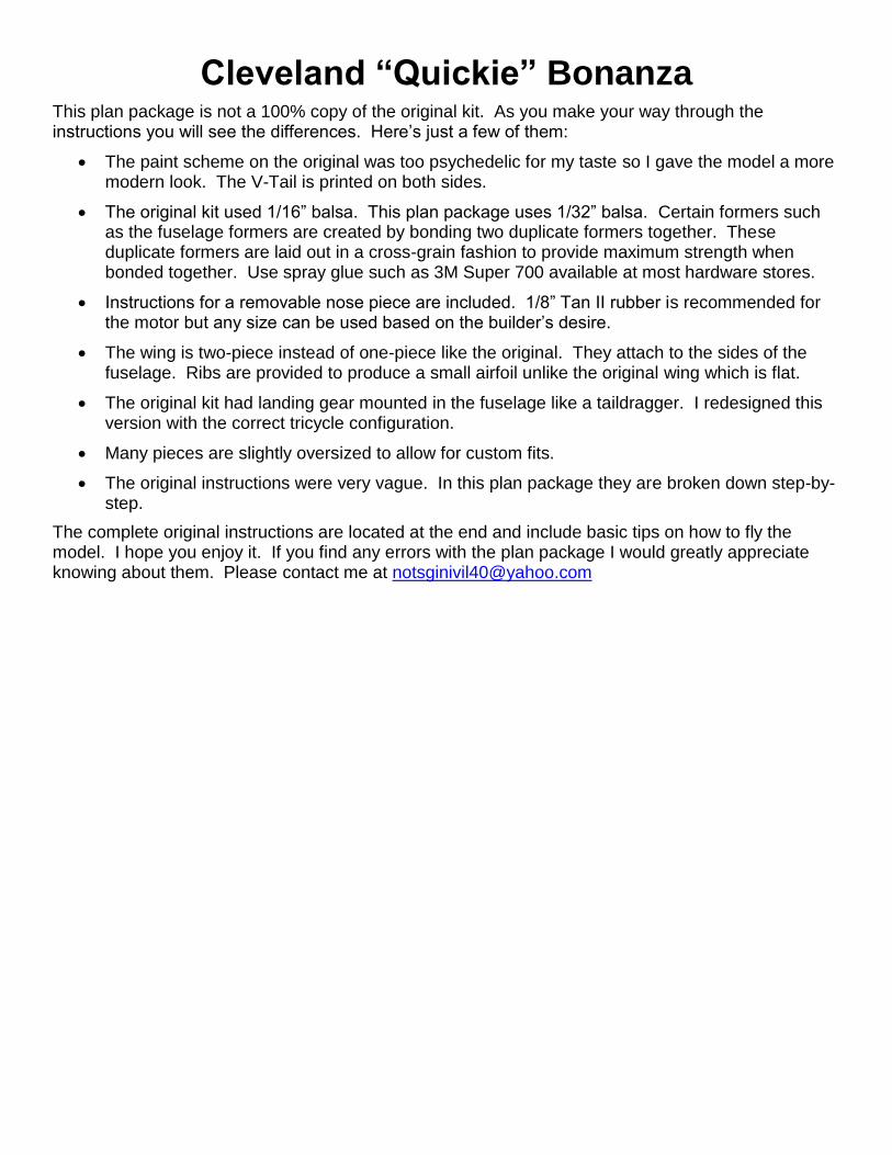
V-Tail pieces are single pieces in this kit. When bonding the two together, use the angle brace as shown.
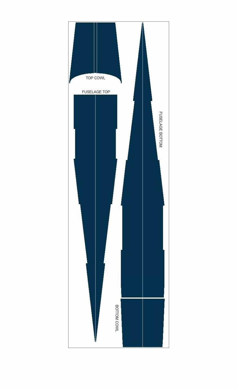
The original kit had each half of the nose top and bottom cowl included as part of each fuselage side. This has been replaced with a one-piece top and bottom cowl that are oversized so they can be trimmed to fit. Install the top cowl at this point by trimming to fit as needed. A penny should be cemented inside the nose to provide nose weight. The nose former provided in this plan package is intended for a removable nose piece.
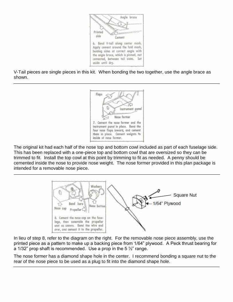
In lieu of step 8, refer to the diagram on the right. For the removable nose piece assembly, use the printed piece as a pattern to make up a backing piece from 1/64” plywood. A Peck thrust bearing for a 1/32” prop shaft is recommended. Use a prop in the 5 ½” range.
The nose former has a diamond shape hole in the center. I recommend bonding a square nut to the rear of the nose piece to be used as a plug to fit into the diamond shape hole.
Square Nut
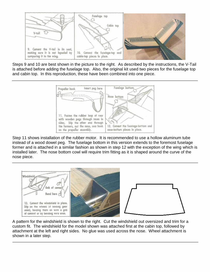
Steps 9 and 10 are best shown in the picture to the right. As described by the instructions, the V-Tail is attached before adding the fuselage top. Also, the original kit used two pieces for the fuselage top and cabin top. In this reproduction, these have been combined into one piece.
Step 11 shows installation of the rubber motor. It is recommended to use a hollow aluminum tube instead of a wood dowel peg. The fuselage bottom in this version extends to the foremost fuselage former and is attached in a similar fashion as shown in step 12 with the exception of the wing which is installed later. The nose bottom cowl will require trim fitting as it is shaped around the curve of the nose piece.
A pattern for the windshield is shown to the right. Cut the windshield out oversized and trim for a custom fit. The windshield for the model shown was attached first at the cabin top, followed by attachment at the left and right sides. No glue was used across the nose. Wheel attachment is shown in a later step.
Two-Piece Wing Assembly Instructions
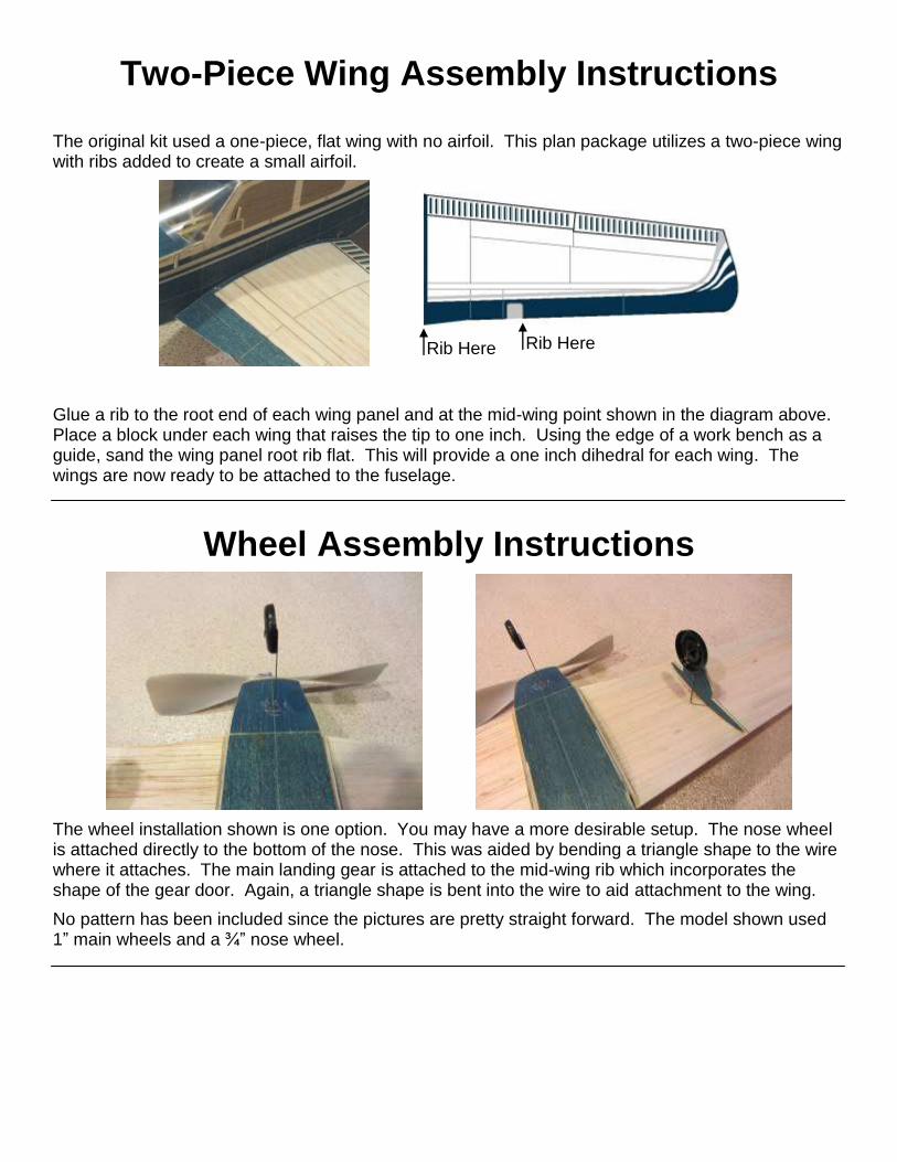
The original kit used a one-piece, flat wing with no airfoil. This plan package utilizes a two-piece wing with ribs added to create a small airfoil.
Glue a rib to the root end of each wing panel and at the mid-wing point shown in the diagram above. Place a block under each wing that raises the tip to one inch. Using the edge of a work bench as a guide, sand the wing panel root rib flat. This will provide a one inch dihedral for each wing. The wings are now ready to be attached to the fuselage.
Wheel Assembly Instructions
The wheel installation shown is one option. You may have a more desirable setup. The nose wheel is attached directly to the bottom of the nose. This was aided by bending a triangle shape to the wire where it attaches. The main landing gear is attached to the mid-wing rib which incorporates the shape of the gear door. Again, a triangle shape is bent into the wire to aid attachment to the wing.
No pattern has been included since the pictures are pretty straight forward. The model shown used 1” main wheels and a ¾” nose wheel.
Rib Here Rib Here