
Cpwoh13f
34
Copyright © 1999 by Ericsson Radio Systems AB 2882 - LZT 123 3315 Rev F Figure 13 - 1 The Workflow of Indoor Cellplanning Capacity dimensioning Choice of antenna and RBS system RF design Nominal antenna configuration Final antenna configuration Installation Frequency planning Traffic control Coverage and capacity demands Tuning
description
Cpwoh13f
Transcript of Cpwoh13f
Copyright © 1999 by Ericsson Radio Systems AB2882 - LZT 123 3315 Rev F
Figure 13 - 1
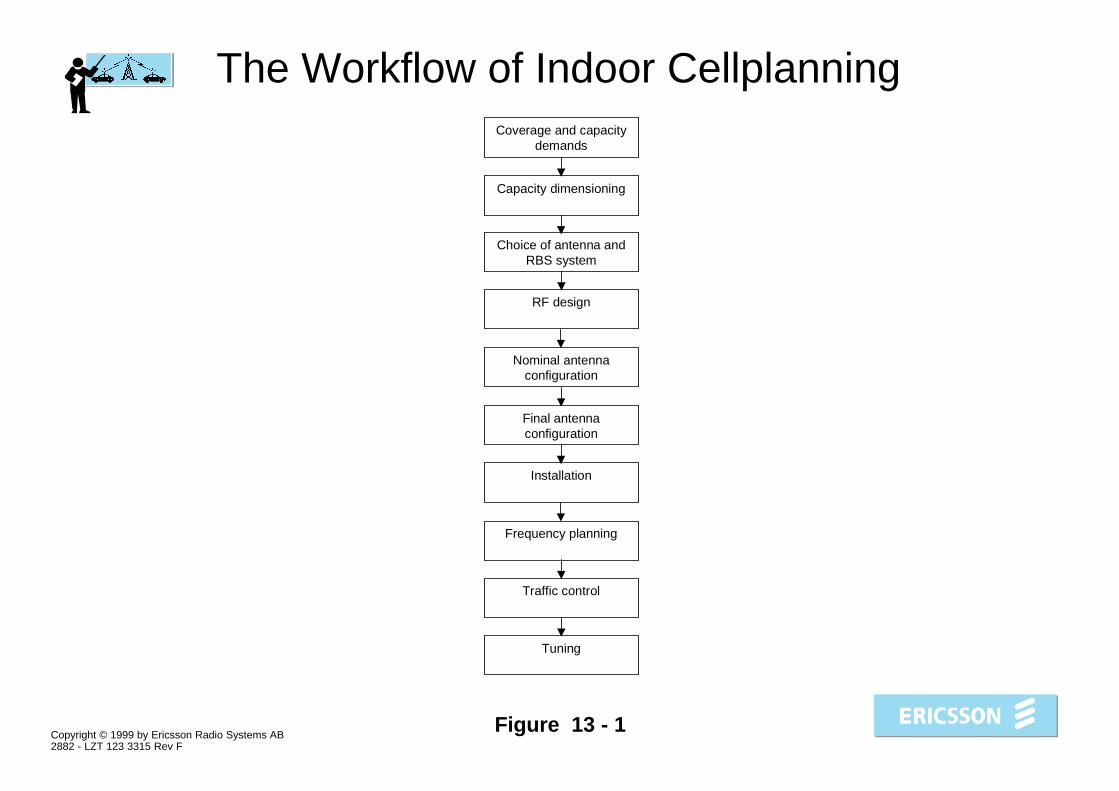
The Workflow of Indoor Cellplanning
Capacity dimensioning
Choice of antenna andRBS system
RF design
Nominal antennaconfiguration
Final antennaconfiguration
Installation
Frequency planning
Traffic control
Coverage and capacitydemands
Tuning

Copyright © 1999 by Ericsson Radio Systems AB2882 - LZT 123 3315 Rev F
Figure 13 - 2
Recommended Cell Plan
Copyright © 1999 by Ericsson Radio Systems AB2882 - LZT 123 3315 Rev F
Figure 13 - 3
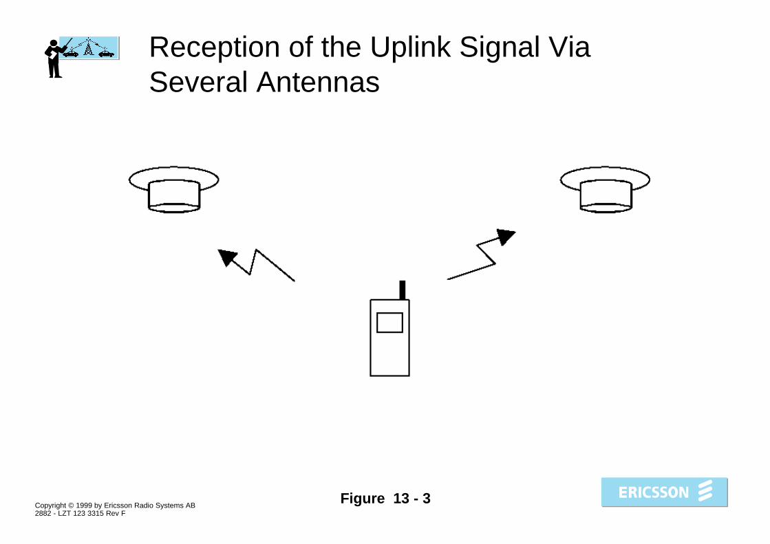
Reception of the Uplink Signal ViaSeveral Antennas

Copyright © 1999 by Ericsson Radio Systems AB2882 - LZT 123 3315 Rev F
Figure 13 - 4
Directional Antennas
Copyright © 1999 by Ericsson Radio Systems AB2882 - LZT 123 3315 Rev F
Figure 13 - 5
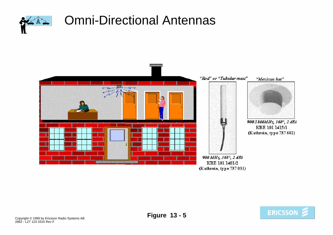
Omni-Directional Antennas

Copyright © 1999 by Ericsson Radio Systems AB2882 - LZT 123 3315 Rev F
Figure 13 - 6
Power Splitters
Copyright © 1999 by Ericsson Radio Systems AB2882 - LZT 123 3315 Rev F
Figure 13 - 7
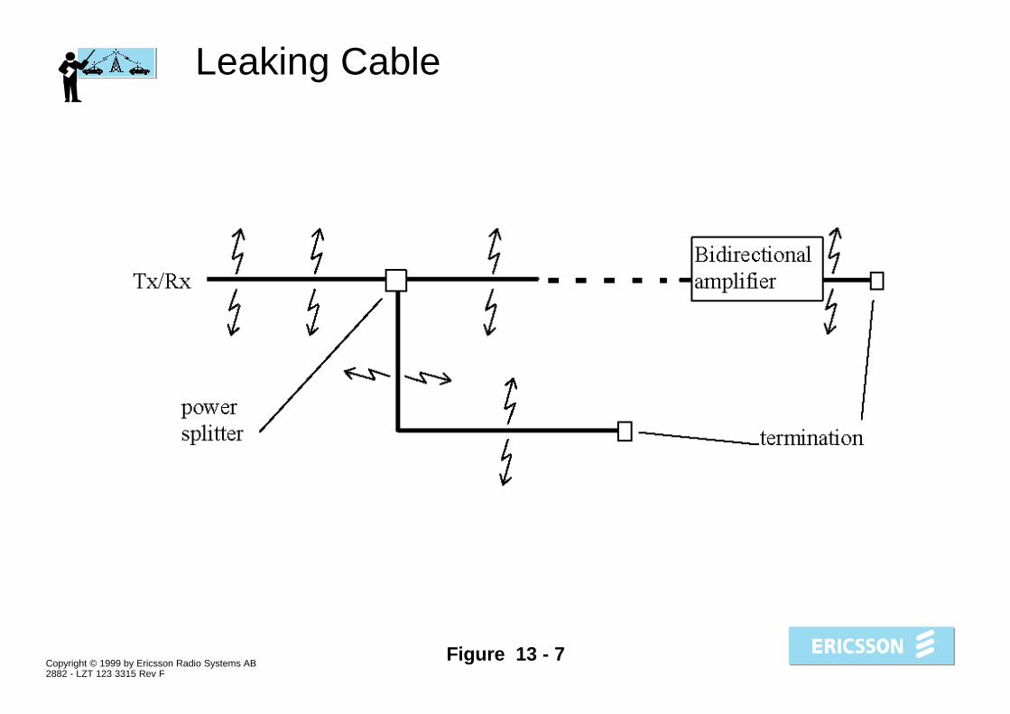
Leaking Cable

Copyright © 1999 by Ericsson Radio Systems AB2882 - LZT 123 3315 Rev F
Figure 13 - 8
Antennas Distributed Via a Fibre-OpticalNetwork

Copyright © 1999 by Ericsson Radio Systems AB2882 - LZT 123 3315 Rev F
Figure 13 - 9
RF-Repeater

Copyright © 1999 by Ericsson Radio Systems AB2882 - LZT 123 3315 Rev F
Figure 13 - 10
RBS Configurations
Copyright © 1999 by Ericsson Radio Systems AB2882 - LZT 123 3315 Rev F
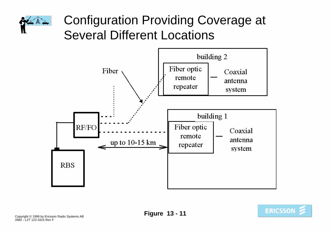
Figure 13 - 11
Configuration Providing Coverage atSeveral Different Locations

Copyright © 1999 by Ericsson Radio Systems AB2882 - LZT 123 3315 Rev F
Figure 13 - 12
MCM In-building Applications
(5,&6621
�[�5%6�����5%6�����ZLWK�&'8�&�
'LVWULEXWHG�LQGRRUDQWHQQD�V\VWHP
Copyright © 1999 by Ericsson Radio Systems AB2882 - LZT 123 3315 Rev F
Figure 13 - 13
Multicasting Matrix Box

Copyright © 1999 by Ericsson Radio Systems AB2882 - LZT 123 3315 Rev F
Figure 13 - 14
Combining Box
*60�����(�7$&6�$036�'�$036���
*60������*60�����'�$036����
5;�7;
'LVWULEXWHGLQGRRUDQWHQQDV\VWHP

Copyright © 1999 by Ericsson Radio Systems AB2882 - LZT 123 3315 Rev F
Figure 13 - 15
RBS 2302, RBS 2202 and RBS 2401

Copyright © 1999 by Ericsson Radio Systems AB2882 - LZT 123 3315 Rev F
Figure 13 - 16
Selection of radio unit in a GSM 900system
(UODQJ�%���*26
���
��
��
2XWSXW�SRZHU�LQ�G%P
�LQFO��FRPELQLQJ�XQLW�V
5%6�����&'8�&���758V
����
��
����
5%6��������XQLWV�
5%6�����&'8�&�� 758V
5%6��������XQLWV�
5%6�����&'8�&�� 758V
��
5%6�����
5%6�����
���� ����
5)�5HSHDWHU

Copyright © 1999 by Ericsson Radio Systems AB2882 - LZT 123 3315 Rev F
Figure 13 - 17
Selection of radio unit in a GSM 1800system
(UODQJ�%���*26
���
��
��
2XWSXW�SRZHU�LQ��G%P,QFO��FRPELQLQJ�XQLW�V
5%6�����&'8�&���758V
����
����
��
����
5%6��������XQLWV�
5%6�����&'8�&�� 758V
5%6�����
���XQLWV�
5%6�����&'8�&�� 758V
����
5%6�����
5%6�����
���� ����
5)�5HSHDWHU

Copyright © 1999 by Ericsson Radio Systems AB2882 - LZT 123 3315 Rev F
Figure 13 - 18
RBS 2401 Antenna Parts
TX0/RX0 TX0/RX0 TX1/RX1 TX1/RX1
���������������������TRX0
RF filtering
TRX1

Copyright © 1999 by Ericsson Radio Systems AB2882 - LZT 123 3315 Rev F
Figure 13 - 19
Antenna Configuration Work Flow
,PSOHPHQWDWLRQ
Copyright © 1999 by Ericsson Radio Systems AB2882 - LZT 123 3315 Rev F
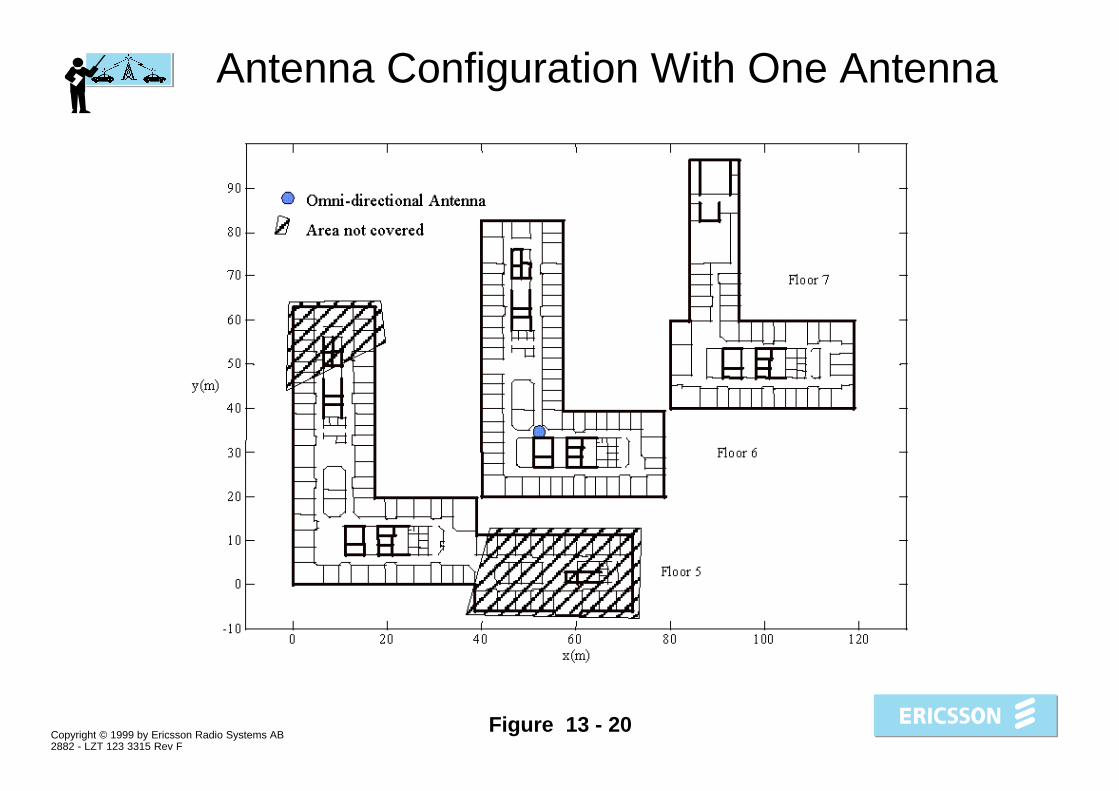
Figure 13 - 20
Antenna Configuration With One Antenna
Copyright © 1999 by Ericsson Radio Systems AB2882 - LZT 123 3315 Rev F
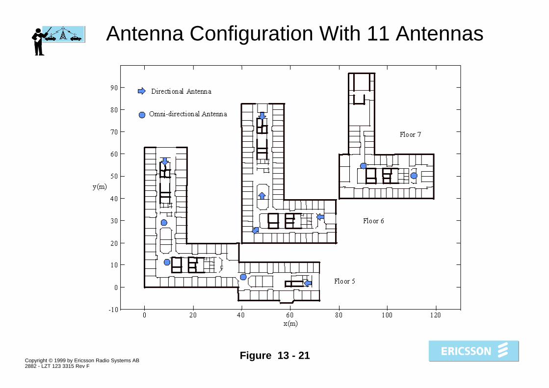
Figure 13 - 21
Antenna Configuration With 11 Antennas

Copyright © 1999 by Ericsson Radio Systems AB2882 - LZT 123 3315 Rev F
Figure 13 - 22
Example of Signal Strength PredictionMade by TEMS Prediction

Copyright © 1999 by Ericsson Radio Systems AB2882 - LZT 123 3315 Rev F
Figure 13 - 23
Free Space Path Loss As a Function ofTransmitter - Receiver Distance

Copyright © 1999 by Ericsson Radio Systems AB2882 - LZT 123 3315 Rev F
Figure 13 - 24
Loss in Free Space Plus Loss in Walls
Copyright © 1999 by Ericsson Radio Systems AB2882 - LZT 123 3315 Rev F
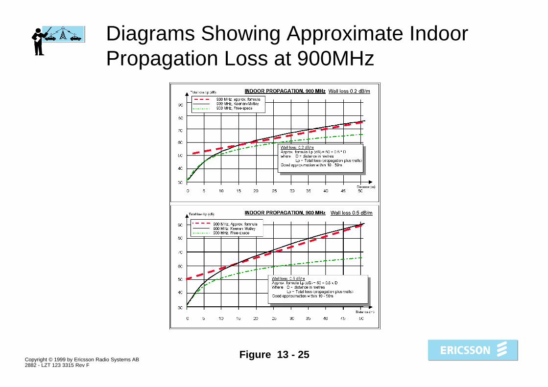
Figure 13 - 25
Diagrams Showing Approximate IndoorPropagation Loss at 900MHz
Copyright © 1999 by Ericsson Radio Systems AB2882 - LZT 123 3315 Rev F
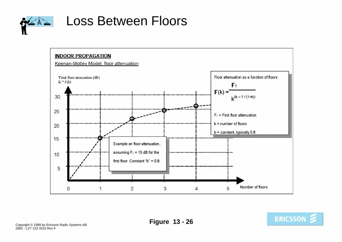
Figure 13 - 26
Loss Between Floors

Copyright © 1999 by Ericsson Radio Systems AB2882 - LZT 123 3315 Rev F
Figure 13 - 27
Recommended Antenna Positioning forEach Floor With One or Several IndoorCells

Copyright © 1999 by Ericsson Radio Systems AB2882 - LZT 123 3315 Rev F
Figure 13 - 28
Recommended Antenna Positioning forEach Floor With Several Indoor CellsWith Very Tight Re-Use
Copyright © 1999 by Ericsson Radio Systems AB2882 - LZT 123 3315 Rev F
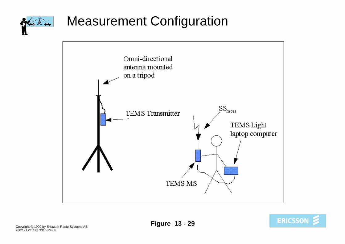
Figure 13 - 29
Measurement Configuration
Copyright © 1999 by Ericsson Radio Systems AB2882 - LZT 123 3315 Rev F
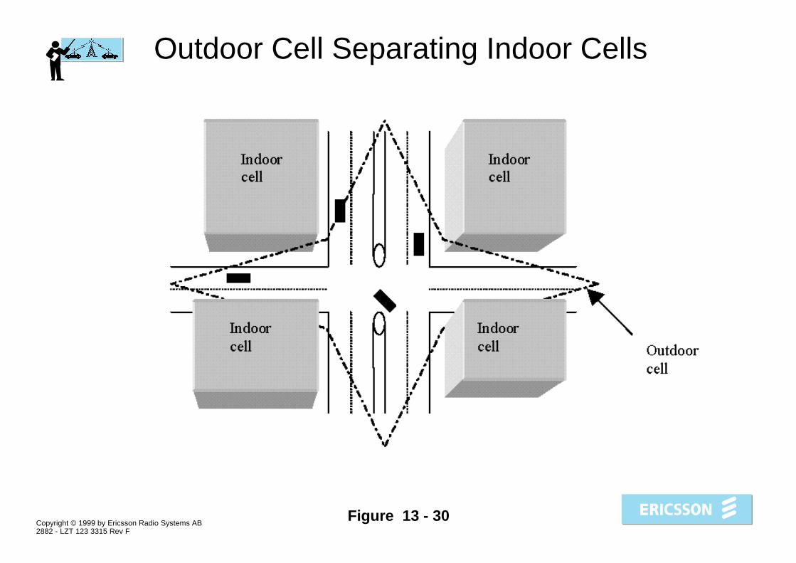
Figure 13 - 30
Outdoor Cell Separating Indoor Cells

Copyright © 1999 by Ericsson Radio Systems AB2882 - LZT 123 3315 Rev F
Figure 13 - 31
Floor 1

Copyright © 1999 by Ericsson Radio Systems AB2882 - LZT 123 3315 Rev F
Figure 13 - 32
Floor 2
Copyright © 1999 by Ericsson Radio Systems AB2882 - LZT 123 3315 Rev F
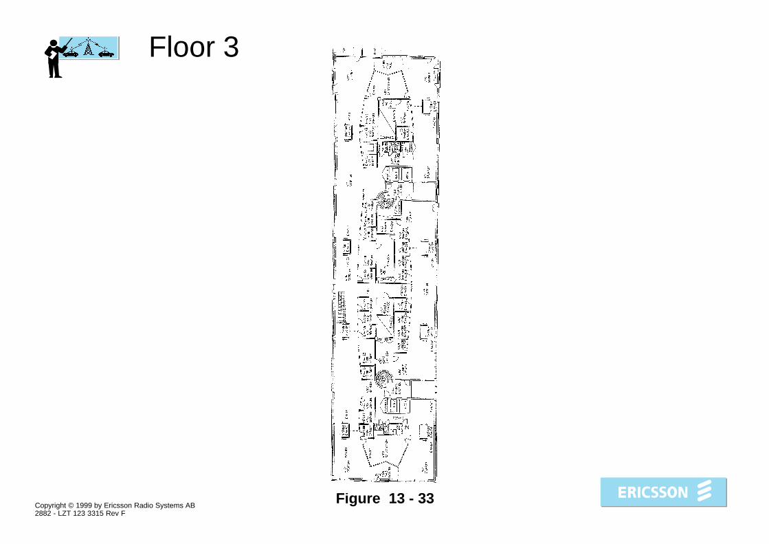
Figure 13 - 33
Floor 3

Copyright © 1999 by Ericsson Radio Systems AB2882 - LZT 123 3315 Rev F
Figure 13 - 34
Floor 4


