CPUville Z80 Computer Serial Interface Kit Instruction...
57
CPUville Z80 Computer Serial Interface Kit Instruction Manual By Donn Stewart © 2016 by Donn Stewart 1
Transcript of CPUville Z80 Computer Serial Interface Kit Instruction...

CPUville Z80 Computer Serial Interface Kit Instruction Manual
By Donn Stewart
© 2016 by Donn Stewart
1

Table of ContentsIntroduction................................................................................................................................................3Building Tips..............................................................................................................................................4Building the Serial Interface......................................................................................................................4Testing and Using the Serial Interface.......................................................................................................8
Using the Serial Port with ROM version 6 and lower...........................................................................8A word about assemblers.....................................................................................................................11Creating a binary machine code (object) file with an assembler.........................................................11Using boot_loader to load a binary program file................................................................................13Using the Serial Port with ROM version 7 and above........................................................................14
Help command................................................................................................................................16Dump command..............................................................................................................................16Load command...............................................................................................................................17Run command.................................................................................................................................19Bload command..............................................................................................................................19Bdump command............................................................................................................................21
Binary transfers on a Linux system.....................................................................................................25Serial Interface Schematic and Explanation............................................................................................34Serial Interface Parts Organizer and List.................................................................................................37ROM Program Listing.............................................................................................................................38User Program Listings.............................................................................................................................56
2

Introduction
The CPUville Z80 Computer Serial Interface Kit is intended for use with the CPUville Z80 computer. Once assembled, you can use the keyboard and display of a PC, or a dumb terminal, to communicate with the Z80 computer using text input and output. The serial interface connects to the computer with the same 16-pin ribbon cable connectors used to connect the bus display. It connects to the serial port on a PC with a straight-through DB9 (9-pin) serial cable. The interface is powered by +5V coming through the ribbon cables – it does not need a separate power supply.
The serial interface is designed to use a legacy communications protocol called RS-232. This protocol dates from the early days of computing. Originally used to connect Teletype machines to each other, it uses a 7-bit code termed ASCII. The code assigns a 7-bit numerical value to each of the characters usedin ordinary English writing, and to some control actions, such as backspace. When connected with a serial interface, two Teletypes could transmit written messages short distances, such as inside a building. Early computers used Teletypes to take input and produce output. A modem could be used to convert the electrical serial signals to tones that could be transmitted over telephone lines, enabling long-distance text communication. Serial interfaces were also used for computer communication with printers or tape drives.
The serial interface protocol is limited in speed. Even high-speed RS-232 interfaces could only send data at about 15,000 characters (bytes) per second. This is not enough to satisfy the demands of moderncomputing, so this protocol has, like the 8-bit computer, become obsolete. However, it is more than adequate for our small Z80 computer, used in the hobby setting. The interface created by the kit runs at 9600 baud, and can transmit about 1000 characters per second. Since the Z80 computer only has 2K RAM space, you can fill its memory in about 2 seconds. So, we have no worries about the “slow” speed of the serial port compared to modern serial transfer protocols, like USB.
The serial interface needs software to run it. The original CPUville Z80 computer kit came with a pre-programmed ROM containing about 300 bytes of program code that allowed the user to run some simple tests and demonstrations, and enter programs bit-by-bit using switches (ROM versions up to 6). With the serial interface comes the potential to use an ordinary keyboard to enter data, and to use a display to receive program output. This greatly increases the power and ease of use of the computer system. However, much more program code is needed to realize this potential. An additional 1400 bytes of code has been added to the ROM (version 7 and higher) to realize this potential. The added code includes a small monitor program that accepts simple commands that allow the user to enter data into memory using hexadecimal characters typed on the keyboard, and execute programs so entered. The monitor also allows memory contents to be displayed on the screen. There are also commands that allow loading of binary program files though the serial port, making programming easier. The ROM also contains code for a variety of utility functions that can be used in programming, such as writing strings to the display, taking text input, and converting between hexadecimal characters and binary data. In all, it makes the Z80 computer begin to behave how most people expect a computer to behave.
3

Building TipsSee the Building Tips section in the CPUville Z80 Computer Kit Instruction Manual.
Building the Serial Interface
Start by putting the parts on the organizer to make sure you have them all, and to get familiar with them.
Once you have checked the parts you can start to solder them onto the circuit board.
The easiest way to solder the components is to start with the shortest (parts that lie closest to the board) and proceed to the tallest. The order is resistor, ICs, sockets, oscillator, capacitors, LED, and DB9 connector. Some components need to be oriented properly, as described below.
1. The resistor can be soldered first. It does not have to be oriented.
4

2. The ICs are soldered next (except the UART – it will be plugged into a socket). The ICs need tobe placed with the little cut-out toward the left:
The ICs can be soldered directly to the board without fear of damage if you use a 15-watt or smaller soldering iron.
3. The two 16-pin and the 28-pin sockets are next. They do not need to be oriented.
4. The oscillator is next. It has to be placed with the sharp corner at the lower left:
5. The capacitors are next. They need to be placed with the positive lead (the long lead, marked with a stripe) toward the left:
5

6. The LED is next. The flat side of the plastic base is oriented toward the right:
7. The DB-9 connector is the last piece. Put a little solder on the side of the clips to ground them to the copper plating of the holes:
Then solder the 9 signal pins.
Once you have finished soldering all the pins on the serial interface board, inspect the board to
6

make sure there are no solder bridges or unsoldered pins. Hold the finished board against a bright light. If you can see light coming through a pin hole, you know you forgot to solder it. This does not apply to the vias, the plated holes where a trace goes from one side of the board tothe other. These can be left open.
7

Testing and Using the Serial InterfaceConnect the serial interface to the computer using the same ribbon connectors used to connect the bus display board. Make sure the connectors are not misaligned:
Connect power briefly to the computer board to make sure the Power indicator on the serial interface board lights up. Check the ICs to make sure none of them are getting hot. If everything is OK, disconnect the power and connect the interface to a PC serial port using a straight-through serial cable (not a “null modem” crossover cable).
On the PC, start a terminal emulation program. I will use the RealTerm program running on a WindowsXP PC for these examples. I prefer RealTerm over Hyperterminal because RealTerm makes transfer of binary data over the serial port easy. Hyperterminal is designed mainly for communication over a modem, and it does not have the ability to do plain binary transfers. I will also give examples using an Ubuntu Linux system running Minicom, and using the command line for binary transfers.
Through the terminal emulation program, set the PC's serial port (usually designated COM1) to 9600 baud, 8-bit words, 1 stop bit, no parity (9600-8-N-1 for short). Set software and hardware flow control off. For terminal settings, set character echo off, and line wrap on. Both ANSI and VT100 or VT102 terminal emulations will work. With the Z80 computer in reset, and the fast clock selected, apply powerto the Z80 computer. The power lights on both the computer and serial interface boards should light. You are now ready to go. But, the Z80 needs some software to communicate with the PC.
The CPUville Z80 computer ROM versions 7 and higher have software code for use with the serial port. Jump to the section on “Using the Serial Port with ROM version 7 and above” to see how to use this code if you have ROM version 7 or higher. If you have a CPUville Z80 computer with a ROM version 6 and below, you can still use the serial port without putting new code in the EPROM. Here is how to do it.
Using the Serial Port with ROM version 6 and lower
In the section titled User Program Listings there is a program you can use to test the serial port connection, echo_char_test. This program can be entered byte-by-byte into RAM using the Program_loader, which is at ROM location 0x0046. The program is only 30 bytes long, and is fairly easy to enter with the Program_loader. Once it is loaded in RAM and executed, it initializes the serial port and waits for input. Then, if all goes well, the characters you type on the PCs keyboard will be sent to the Z80 by the serial port, and the Z80 computer will echo them back to the display. The
8

characters will also be displayed on the Z80 computer's port 0 LEDs. The following is some detail about how to do this.
You should have the Z80 computer and serial interface connected to the PC serial port, a terminal emulation program such as RealTerm running with the proper communications parameters (see above), with the Z80 in reset, and the fast clock selected. Apply power to the Z80 and serial interface (the power light on the serial interface should light).
Put the Program_loader address on the input port switches (0x0046). Take the Z80 out of reset and load the 30 bytes of the echo_char_test program. The Program_loader is described in the CPUvilleZ80 Computer Instruction Manual. After the last byte has been entered, run the program (close the leftmost switch on input port 1).
Look at the terminal emulation program window. The CTS and DSR signals should now be active, indicating the the UART on the Z80 computer's serial interface has been initialized.
Click the mouse in the terminal program window. Type characters on the keyboard. They should appearon the terminal program display:
9

You might note some odd characters, depending on what the keyboard is sending. Up and down arrow may change lines, return may send the cursor back to the start of the line. If the characters are being echoed, you can be sure the serial port is set up properly and is working. Nothing you enter on the keyboard can physically damage the Z80 computer or the PC, so feel free to experiment.
But entering programs byte-by-byte with the input port switches is difficult, and it is easy to make a mistake. What one really wants is a way to load binary code generated by an assembler program directly into the Z80 computer's memory through the serial port, and execute it. For this, we can use theboot_loader program (see “User Program Listings”). This is another tiny program that can be entered into the Z80 computer's memory using the Program_loader. After it is entered, it can be used to loadother programs. It will stay active and usable for entering programs, as long as the Z80 is powered on.
Once boot_loader is entered and executed, the Z80 initializes the serial port UART and waits for input from the PC. You start the binary transfer from the PC, and the Z80 computer will receive 256 bytes of code and place them in its memory starting at location 0900h. Then, the boot_loader jumps to that location to execute the code that was entered. If you don't overwrite it, the boot loader will remain in memory at 0x0800, and will start again after the computer is reset, if you put 0x0800 on the input port switches. This allows you to write, assemble, run, and debug Z80 assembly language programs.
To demonstrate how to use the boot_loader we first need to create a binary file that boot_loader can load and execute. We will use an assembler program running on the PC to create the binary file.
In the “User Program Listings” there is another echo_char program, but this one is designed for loading using the boot_loader. It is the same as echo_char_test except it lacks the port initialization commands, and has padding at the end to make the assembler output binary file greater than 256 bytes long (if it was less than that the boot_loader would hang). We will make a binary program file from this assembly language file using an assembler program.
10

A word about assemblers.
There are many assembler programs for the Z80 that are available for download. Most of them are free.Many of them date from the early days of personal computing, and they often have some quirks. I use the z80asm program running under Ubuntu Linux for most of my work, and the TASM assembler in Windows1.
Most Z80 assemblers use the same, standardized mnemonics for the Z80 operation codes2. However, the various assemblers may use different variants or syntax for the assembler directives. In z80asm, directives are entered plain, but in TASM directives require a leading period. So, the z80asm org directive, is .org in TASM. z80asm has the defs (define space) directive, which fills a block with data, but TASM has the .fill directive. Also, TASM being a DOS-era command line program, wants input filenames with no more than 8 characters in their names, and those 8 characters have to be unique to the directory the files are in. If you have more than 8 characters, and those characters are unique, it will complain with a source file read error. Strangely, if you have a well-behaved file name that is unique in its directory, like echo_ch, it will not complain if you give TASM the file name echo_char, even thoughthat name has 9 characters. It simply ignores the last 2 characters and loads the echo_ch file! Took me awhile to figure that out. Anyway, that is enough about assemblers.
Creating a binary machine code (object) file with an assembler
If you look at the boot_loader code, you see that it has the UART initialization codes. Once the UART has been initialized, other programs using it should not try to initialize it again. So, if we use theboot_loader to load another program, and that second program uses the serial port, it should not have the initialization codes. The echo_char_test program we entered directly using the Program_loader has initialization codes, so it is not an appropriate test program to load with the boot_loader. I wrote another program that will echo characters, but this program does not have the initialization codes. I will use TASM running under Windows to assemble the binary echo_char file, and will load and execute it using the boot_loader and RealTerm. Since I am using TASM for this exercise, I show the echo_char assembly language edited for compatibility with that assembler.
To start, create the assembly language file with a text editor like Notepad, and save that file as echo_ch.asm in the TASM directory:
1 This TASM is the “Telemark Assembler” for the Z80, not the Borland Turbo-assembler for x86 processors. Both assemblers have a TASM executable, but only the Z80 assembler will create the Z80 machine code.
2 There are some exceptions: the Z80 assembler by Joe Moore, AS8080, generates Z80 machine code, but uses Intel/TDL mnemonics for its assembly files.
11

The TASM command line to assemble this program looks like this:
The TASMP executable file is used, because Windows XP runs in protected mode. In DOS, the TASM program is used instead (real mode). The -80 option tells TASM that we are assembling Z80 assembly language (TASM can assemble a wide variety of languages). The -b option tells TASM to create a binary object file output. Its default is a hex output file.
If TASM is successful it will show a window like this:
If your program has sytax errors, they will be shown here. Correct the errors as needed. When you havea successful assembly, you can close the window.
TASM should have put the binary output file, named echo_ch.obj in its directory. This is the file we will load into the Z80 computer, using the boot_loader.
12
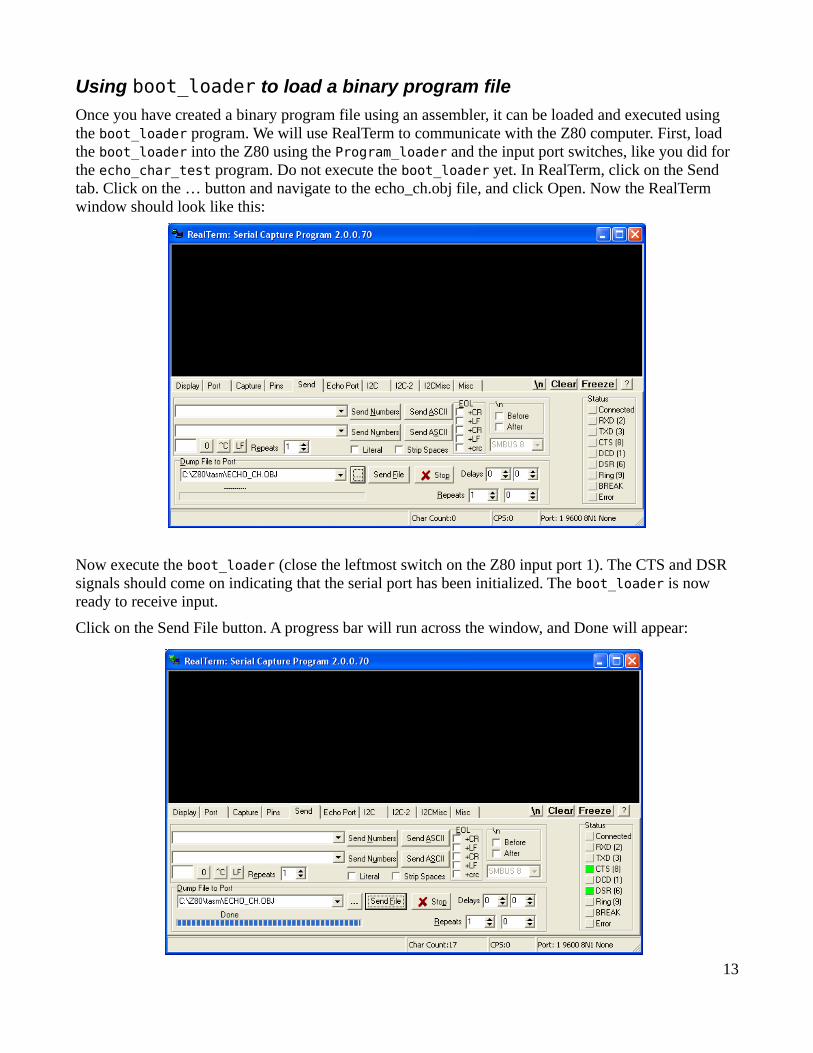
Using boot_loader to load a binary program file
Once you have created a binary program file using an assembler, it can be loaded and executed using the boot_loader program. We will use RealTerm to communicate with the Z80 computer. First, load the boot_loader into the Z80 using the Program_loader and the input port switches, like you did for the echo_char_test program. Do not execute the boot_loader yet. In RealTerm, click on the Send tab. Click on the … button and navigate to the echo_ch.obj file, and click Open. Now the RealTerm window should look like this:
Now execute the boot_loader (close the leftmost switch on the Z80 input port 1). The CTS and DSR signals should come on indicating that the serial port has been initialized. The boot_loader is now ready to receive input.
Click on the Send File button. A progress bar will run across the window, and Done will appear:
13

Now click the mouse in the RealTerm display window, and type on the keyboard. You should see your characters being echoed onto the display (and on the port 0 LEDs):
If you feel limited by the 256-byte transfer size of the boot_loader, you can of course write a programthat will in turn load a much larger program. This is the meaning of the “boot” in boot_loader: the computer is “pulling itself up by its own bootstraps”, by running a tiny program entered using the switches, which loads a larger program, which in turn loads a larger program, up to the limits of the size of the memory.
But, what you really want is the equivalent of a boot_loader program (and others) in the ROM, so you don't have to mess with the input switches. The following section discusses using the serial port with ROM version 7 and above, which has code to run the serial port.
Using the Serial Port with ROM version 7 and above
If you look at the “ROM Program Listing” below, you will see that starting at address 0x0100 a lot of code has been added compared to ROM version 6 and earlier. There are a variety of utility subroutines that are used with the serial port for getting input with line editing, writing lines (strings) to output, and converting between characters and values. You can use the subroutines in your own programs.
In addition to the utility subroutines, there is a primitive monitor program that takes some simple commands that allow you to enter and run programs on the Z80 computer without needing to use the input port switches. It can all be done using the keyboard and display, through the serial port.
The monitor program has two entry points. The monitor_cold_start is used when the computer is taken out of reset. It has the UART initialization commands. The monitor_warm_start is used to handcontrol back to the monitor after a user program has been run.
I will show examples using the monitor program with a PC running the RealTerm program. Start RealTerm, and make sure it is set up for 9600 baud, 8-N-1 communications (under the Port tab). Select
14

the display as Ansi option under the Display tab. Real term uses a default of 16 rows in its display window, but you should increase this to 24 rows.
With the Z80 in reset, place the monitor cold start entry address 0x04C0 on the input port switches, andtake the Z80 out of reset. You should see the monitor greeting message on the display, and a > characteras a prompt indicating the monitor is ready to take input:
You need to click in the display window to enter text into RealTerm. Type help or ? to get a display of the available monitor commands:
15

The monitor program is very simple. It has to be, to fit in 1.8 K of memory. Commands are case-sensitive (lower case only), and no arguments are accepted. Hexadecimal numerals need to be entered with upper-case A through F. There is little or no error checking or memory management. The input line buffer is located at memory location 0x0F88, and if you put in a huge input line, it will overwrite the stack and the system will fail. The buffer is not cleared after most commands, so if you hit return ona blank line, you might find that you have re-executed your last command. But, it seems to work well ifyou stay within reasonable limits. The worst you can do entering commands is to cause the Z80 system to fail. If that happens, just reset. Here is a discussion and examples using the various commands.
Help command
Displays a list of the available commands. The ? does the same thing.
Dump command
Displays a 256-byte block of the Z80 computer's memory. The command takes a 4-character hexadecimal address as input, with the A through F characters as upper case. The output display shows the 4-character hexadecimal address of the first byte of each row, then 16 bytes of data as hexadecimal characters. Here is a dump display of the first 256 bytes of the ROM:
16

This command is very useful for debugging programs, as you can see the machine code, and the values of your variables.
Load command
This command takes input from the keyboard, as hexadecimal characters, and loads the input into memory as binary code. Hit return to stop the input. During the load, the display shows 16-byte rows ofinput data in a manner similar to the dump command, without the addresses. Here is an example, entering the first 16 hexadecimal numbers into RAM starting at location 0x0800:
17
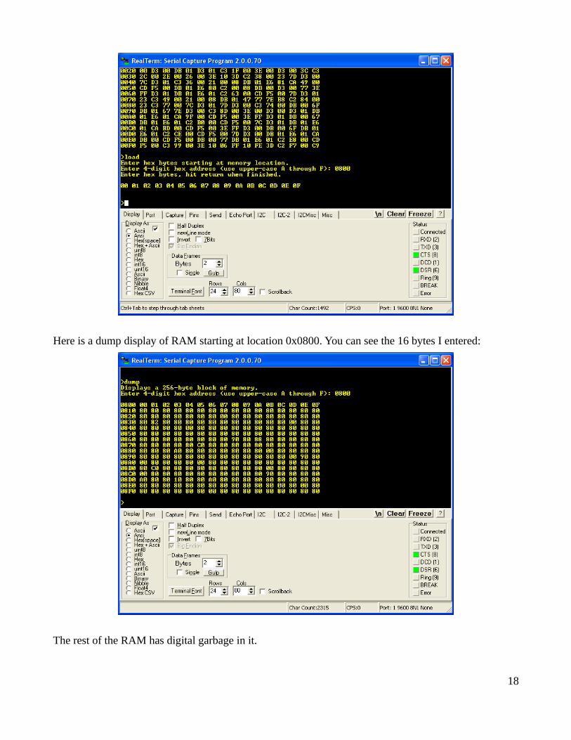
Here is a dump display of RAM starting at location 0x0800. You can see the 16 bytes I entered:
The rest of the RAM has digital garbage in it.
18

You can use the load command to quickly change a byte of program code or a variable, to clear memory by putting in zeros (just hold down the zero key, the repeats from the keyboard are entered), and to load small programs by hand.
Run command
This command causes program control to be passed to the address you enter. It is the same as the Jump command.
Bload command
This command is for loading binary files (binary load). The command takes a four-character hexadecimal address input, and a decimal file length input. Then, it waits for the file to be sent from thePC to the Z80. It works best if you enter the exact length of the binary file. The bload command will hang if the file is shorter than the length you enter.
The following is an example of loading a binary file using the bload command. We will load and execute the echo_ch program that was assembled to test the boot_loader program (see the section above for details of how to assemble the file).
We can load the file anywhere in RAM, but let's load it at location 0x0900. First we need the exact file size, which we can obtain by hovering over the file name, or right-click-Properties:
We see the file is 272 bytes long. Now we run the bload command, and enter the target address 0900h (no need to type the “h” in the monitor), and the length as decimal 272. Hit return after entering the length, and it lets you know it is ready to receive the file. Now, in the RealTerm Send tab, navigate to
19

the echo_ch.obj file using the … button, click Open, then click the Send button. After the file is sent “Done” should appear above the file progress bar, and the monitor prompt should reappear, letting you know the command was successfully executed:
You can examine the memory at 0900h using the dump command:
20

There you see the program bytes, followed by the padding zeros that were put in for the boot_loader program (see above – no padding needed for the bload command since it loads the number of bytes youenter).
You may now run the program using the run command, enter the address 0900h. Characters you type are echoed to the screen. For a neater display click the \n button on the RealTerm display. This sends the cursor to a new line.
The echo_ch program has no exit, so you need to reset the Z80 computer to get out of it. When you take the Z80 out of reset, the monitor program starts again, since you have the cold start entry point on the input port switches. Resetting the Z80 does nothing to the memory contents. After you reset the computer, You can see that the echo_ch program is still present at location 0900h using the dump program, and you can run it again using the run command. If you want to write a program to return to the monitor on exit, you need to put in an instruction to jump to the monitor_warm_start entry point at 0x04C9 on program termination.
Bdump command
This command dumps a segment of binary data from memory to the serial port. It is up to the PC on theother end to capture this output into a file. We can do this using RealTerm.
The echo_ch program we loaded has a lot of padding bytes, to make it useful for the boot_loader. Wecan create a shortened version of it using bdump.
If you look at the memory dump display (or the list file) for echo_ch, you can see that the last byte of the program is the EA at address 0915h, meaning the total number of program bytes is decimal 20 (you can use a calculator program with hexadecimal inputs if you need to figure out file lengths of longer programs). We can create a more compact file by dumping these first 20 bytes from memory to a file that we can name echo_char.bin (we don't need to worry about the length of the file name now because TASM will not be involved – see discussion above in “A Word About Assemblers”).
To create this compact echo_char.bin file, we first set up RealTerm to receive a file of this name. Click on the Capture tab. Write the file name (with complete path) in the File window. Make sure Direct Capture is checked. While RealTerm can capture a file of any length, I have found that it is most accurate if the number of bytes is a multiple of 16. Here I chose to capture 32 bytes. Enter the bdump command, address 0900, number of bytes to dump 32 and hit return. Now, the Z80 is ready to send those 32 bytes to the serial port with any keypress.
21

Click on the Overwrite button. The bottom of the display turns red, indicating that capture is underway.But, the Z80 computer has not sent any bytes yet.
Now, click in the display window and hit any key. The 32 bytes will be transferred to the file
22

echo_char.bin and the RealTerm display will go back to its normal color. The Char Count will show 32 bytes transferred. In the display window, the monitor prompt will re-appear.
Navigate to the directory containing the echo_char.bin file, and check its size in the Properties window. You can see it is 32 bytes.
This file can be loaded back into the Z80 using bload. I first entered FFs into the Z80 memory at 0900husing the load command before loading back the file so you can see that it is really now just 32 bytes long:
23

Here is the dump display after loading the shortened echo_char.bin file:
24

Now you can run the program. Press the \n button on the RealTerm window to put the cursor down a couple of lines and type some text:
This concludes the discussion of using the monitor program commands with RealTerm, running under Windows XP. The next section shows how to use the monitor commands with Minicom running on a Linux system.
Binary transfers on a Linux system
I have used a Linux system for most of my work on this project, and I suppose many hobbyists use it too. The terminal emulation program I use is Minicom. It is not as capable as RealTerm in that it does not have built-in ability to do binary transfers. However, the Linux operating system itself has very robust command line functions that can accomplish this.
Open a terminal window and start Minicom:
25

Using ctrl-A-Z, get to the cOnfiguration menu, and make sure you have the correct serial device designated, the correct baud rate, and 8-N-1 communications.
You can also set the communications parameters using the comm Parameters menu:
26

You can save these settings as the default. Once Minicom is configured you can take the Z80 computer out of reset, with the monitor_cold_start address 0x04C0 on the input port switches. You should see the monitor greeting message, followed by the monitor prompt and cursor:
The help, dump, and load commands work the same way as with RealTerm (see the sections above). However, Minicom has no ability to send or receive plain binary files, so some extra work needs to be done.
To send a binary file to the Z80 computer we still use the bload command. But, we have to switch fromMinicom to the Linux command line in order to send the file over the serial port. We can do this easily
27

by opening another terminal window next to the window running Minicom, and using the command line in the second terminal window to send the file using the Linux cat command. Here is an example using the echo_char file:
28

Here are the two terminal windows side-by-side. The left window is running Minicom, and the right is just a plain terminal. Whichever window you click in becomes the active window. Both windows can access the serial port, as long as only one is using it at a time.
We started in the right hand window, listing the files in the directory to make sure we have the correct file size. We see the echo_char.bin file,previously assembled using z80asm, with a size of 272 bytes. We will transfer this file.
Then, we switched to the left window and set up a binary load for this file using the bload command, as shown above. When bload gives the “Ready to receive, start transfer” message we switch back to the right window and enter the cat command as above. This command is normally used to dump a text file to the terminal display window, or to concatenate files together. But, it will also dump a binary file. We redirect the cat command output to the serial port with the redirection symbol >, followed by the device name of the serial port. Hit return, and cat sends the contents of echo_char.bin to the serial port, and into the Z80 computer's memory as directed by bload. After the transfer, the right hand display returns to the terminal command line, and the left hand display to the monitor command line:
29

After the transfer, we can do a dump display to show that the file is in the Z80's memory:
30

To do a binary transfer from the Z80's memory to a binary file on the PC, we use the monitor bdump command, and the Linux head command. The head command is from the Unix roots, and was used to display some number of characters (the header) of a text file on the display screen. However, using redirection, we can send the “header” of the serial port output (everything's a file in Linux) to a file on the disk. We tell the head command how many bytes to get and put into the file.
By looking at the memory dump display you can see that only the first 22 bytes of the echo_char.bin file are program code. We can therefore dump these 22 bytes starting at memory location 0900h from the Z80 computer through the serial port to the PC, and the Linux head command running in the PC will put this data into a file. We will name the new file echo_char_2.bin.
We set up the transfer in the left-hand window, where Minicom is communicating with the Z80's monitor program. We get to the point wherewe see the message to hit any key, then go to the right hand window. There, we set up the head command to receive 22 bytes from the serial port device, and redirect these bytes into the echo_char_2.bin file. Here is the transfer ready to go:
31

To do the transfer, we go to the right hand window and hit return to start the head command. It is now waiting to receive 22 bytes from the Z80 through the serial port. Then, we go to the left hand window and hit any key. Once the transfer has finished, the left hand window will show the monitor prompt, and the right hand window will go back to the terminal command line. To see that the file has been successfully transferred, list the local directory in the right hand window:
32

You can see the echo_char_2.bin file now, with the correct file size. This file can be loaded back into the Z80 using bload, and run, and its memory examined to verify that the transfer proceeded without error. On some systems, you may need to add the -q or –quiet option to the head command to do the transfer. There are probably other ways to do binary transfers (using the Linux dd command for example) but the cat and head commands seem to work well, and are simple to use. This concludes the section about using the Z80's monitor program commands.
There are many utility subroutines in ROM version 7 and above that you can use in writing your own programs. By examining the ROM listing you can see these subroutines. The ROM listing is commented, so you can probably figure out how the subroutines work, how to passvalues, and how the subroutines return data to your program. To use a subroutine in your own programs, you need to put the subroutine entrypoint labels in a header, with the entry point addresses. For example, if you want to use the get_line subroutine, put this line in your assembly language file:
get_line: equ 0149h
Then you can use call get_line in your code to call the subroutine, and get input data from the keyboard. The other subroutines can be used in a similar way. Feel free to contact me if you have any questions about the ROM subroutines, or how to use them in programs.
33

Serial Interface Schematic and Explanation
34
The main IC is the UART (Universal Asynchronus Receiver/Transmitter). The heart of this device is shift register. The shift register accepts parallel input from the 8 data bus lines D7 to D0, and then, driven by a clock input, shifts this 8-bit word one bit at a time onto a single serial output, labeled TxD for transmitted data. Similary, a serial input can be clocked one bit at a time through the RxD input into the shift register, and the resulting 8-bit word read out onto the parallel data bus. The UART has bidirectional data inputs/outputs so it can be connected directly to the computer data bus.
The NAND gate U1 A is used for the chip select logic, to make sure the UART chip is selected only when the proper input/output instructionand port address are used. The other NAND gates are configured as inverters to create the proper Read, Write, and Reset inputs for the UART.
Standard RS-232 serial ports use defined baud (bits-per-second) rates to send and receive serial data. To create an acceptable baud rate, a 1.8432 MHz signal from the oscillator is divided by 12 by the 74LS92 chip to yield a 153600 baud signal. This signal is fed to the TxC and RxC (transmitter and receiver clock) inputs, and is divided by 16 inside the UART, to create the final 9600 baud rate used in the interface. The computer 2 MHz system clock is fed to the UART Clock input which is used for internal fine timing to find the center of the incoming and outgoing serial bits, and for timing inputs and outputs to the data bus. The system Reset signal, which resets the Z80, is also sent to the UART. After a reset, the UART needs to be initialized by writing mode and command words to its control port. See the ROM listing for details.
The RS-232 serial communication protocol requires the serial data bits to have voltage levels of + or – 5 to 25 V. The voltage range between + 3 and -3 V is invalid. This design helps reduce noise on the interface. However, the power supply for the Z80 computer can only supply +5V, not -5V, so it cannot be used directly for serial communication over this interface. The MAX232N chips are specially designed to createthe proper voltages for RS-232 serial communications using a single +5V power source. They use the 1 uF capacitors and internal circuitry to create a “charge pump” to boost the voltage to proper levels. In this interface they create about + and – 8V.
Devices connected by a serial cable can be of two types, designated DTE (data terminal equipment) and DCE (data communication equipment). This comes from the early days when a Teletype (DTE) was connected to a modem (DCE) to allow text communication over phone lines. The serial signal transmitted from the Teletype on pin 2 of its 25-pin connector was received by the modem on the same pin. The signal was called TxD because the DTE defines the signal names. But inside the DCE, this signal had to be sent to the modem's UART RxD input, so it changes names once inside the interface. I designed this serial interface as DCE, because many people will have straight-through serial cables from connecting a PC (which has a DTE serial port) to a modem, and this same cable can be used to connect a PC to the Z80 computer. You can see that the RS-232 TxD signal on pin 3 of the 9-pin connector changes names inside the interface, and goes to the RxD input on the UART. The same is true of the TxD from the UART, going to the RS-232 RxD signal (pin 2) on the connector. The other signals, DSR, DTR, CTS, RTS are used by the connected devices to signal each other that they are able to receive or transmit. These signals can be read and written by the UART control/status port. The only one important in this interface is the RTS signal, which is fed to the CTS input on the UART. If this signal is not active, the UART will not send data. If your DTE cannot provide this signal for some reasonyou can just ground the UART pin 17 to allow transmission. The other signals can be used to allow hardware flow control, but this is not
35

needed for this Z80 computer. In fact, if CTS on the UART is grounded, you can do serial communications with just three wires, TxD, RxD and ground.
36

Serial Interface Parts Organizer and ListCapacitor, 1 uF tantalum
10
Red LED
1
Resistor, 470 ohmYellow-Violet-Brown
1
DIL16 socket
2
DIL28 socket
1
DB9 female connector
1
74LS00
1
Oscillator 1.8432 MHz
1
8251A UART
1
74LS92
1
MAX232N
2
C1to C10 1 uF tantalumD1 LEDIDC1 and 2 DIL16 socketJ1 DB9 femaleR1 470 ohmU1 74LS00U2 OSC 1.8432 MHzU3 8251A UARTU3 socket DIL28 socketU5 74LS92U6 and U7 MAX232
Note: There is no U4
37

ROM Program Listing
# File 2K_ROM_7.asm0000 org 00000h 0000 Start_of_RAM: equ 0x0800 0000 c3 18 00 jp Get_address ;Skip over message 0003 .. 00 defm "CPUville Z80 ROM v.7",0 0018 db 00 Get_address: in a,(0) ;Get address from input ports 001a 6f ld l,a 001b db 01 in a,(1) 001d 67 ld h,a 001e e9 jp (hl) ;Jump to the address 001f db 00 Port_Reflector: in a,(0) ;Simple program to test ports 0021 d3 00 out (0),a 0023 db 01 in a,(1) 0025 d3 01 out (1),a 0027 c3 1f 00 jp Port_Reflector 002a 3e 00 Simple_Counter: ld a,000h ;One-byte counter for slow clock 002c d3 00 Loop_1: out (0),a 002e 3c inc a 002f c3 2c 00 jp Loop_1 0032 2e 00 Count_to_a_million: ld l,000h ;Two-byte (16-bit) counter 0034 26 00 ld h,000h ;Clear registers 0036 3e 10 Loop_2: ld a,010h ;Count 16 times, then 0038 3d Loop_3: dec a 0039 c2 38 00 jp nz,Loop_3 003c 23 inc hl ;increment the 16-bit number 003d 7d ld a,l 003e d3 00 out (0),a ;Output the 16-bit number 0040 7c ld a,h 0041 d3 01 out (1),a 0043 c3 36 00 jp Loop_2 ;Do it again 0046 21 00 08 Program_loader: ld hl,Start_of_RAM ;Load a program in RAM 0049 db 01 Loop_4: in a,(1) 004b e6 81 and 081h ;Check input port 1 004d ca 49 00 jp z,Loop_4 ;If switches 0 and 7 open, loop 0050 cd f5 00 call debounce 0053 db 01 in a,(1) ;Get input port byte again
38

0055 e6 80 and 080h ;Is the left switch (bit 7) closed? 0057 c2 00 08 jp nz,Start_of_RAM ;Yes, run loaded program 005a db 00 in a,(0) ;No, then right switch (bit 0) closed. 005c d3 00 out (0),a ;Get byte from port 0, display on output 005e 77 ld (hl),a ;Store it in RAM 005f 3e ff ld a,0ffh ;Turn port 1 lights on (signal that 0061 d3 01 out (1),a ;a byte was stored) 0063 db 01 Loop_6: in a,(1) ;Wait for switch to open 0065 e6 01 and 001h 0067 c2 63 00 jp nz,Loop_6 006a cd f5 00 call debounce 006d 7d ld a,l ;Put low byte of address on port 1 006e d3 01 out (1),a 0070 23 inc hl ;Point to next location in RAM 0071 c3 49 00 jp Loop_4 ;Do it again 0074 21 00 08 Memory_test: ld hl,Start_of_RAM ;check RAM by writing and reading each location0077 db 01 Loop_8: in a,(1) ;read port 1 to get a bit pattern 0079 47 ld b,a ;copy it to register b 007a 77 ld (hl),a ;store it in memory 007b 7e ld a,(hl) ;read back the same location 007c b8 cp b ;same as reg b? 007d c2 84 00 jp nz,Exit_1 ;no, test failed, exit 0080 23 inc hl ;yes, RAM location OK 0081 c3 77 00 jp Loop_8 ;keep going 0084 7c Exit_1: ld a,h ;display the address 0085 d3 01 out (1),a ;where the test failed 0087 7d ld a,l ;should be 4K (cycled around to ROM) 0088 d3 00 out (0),a ;any other value means bad RAM 008a c3 74 00 jp Memory_test ;do it again (use a different bit pattern) 008d db 00 Peek: in a,(0) ;Get low byte 008f 6f ld l,a ;Put in reg L 0090 db 01 in a,(1) ;Get hi byte 0092 67 ld h,a ;Put in reg H 0093 7e ld a,(hl) ;Get byte from memory 0094 d3 00 out (0),a ;Display on port 0 LEDs 0096 c3 8d 00 jp Peek ;Do it again 0099 3e 00 Poke: ld a,000h ;Clear output port LEDs 009b d3 00 out (0),a 009d d3 01 out (1),a 009f db 01 Loop_9: in a,(1) ;Look for switch closure
39

00a1 e6 01 and 001h 00a3 ca 9f 00 jp z,Loop_9 00a6 cd f5 00 call debounce 00a9 3e ff ld a,0ffh ;Light port 1 LEDs 00ab d3 01 out (1),a 00ad db 00 in a,(0) ;Get hi byte 00af 67 ld h,a ;Put in reg H 00b0 db 01 Loop_11: in a,(1) ;Look for switch open 00b2 e6 01 and 001h 00b4 c2 b0 00 jp nz,Loop_11 00b7 cd f5 00 call debounce 00ba 7c ld a,h ;Show hi byte on port 1 00bb d3 01 out (1),a 00bd db 01 Loop_13: in a,(1) ;Look for switch closure 00bf e6 01 and 001h 00c1 ca bd 00 jp z,Loop_13 00c4 cd f5 00 call debounce 00c7 3e ff ld a,0ffh ;Light port 0 LEDs 00c9 d3 00 out (0),a 00cb db 00 in a,(0) ;Get lo byte 00cd 6f ld l,a ;Put in reg L 00ce db 01 Loop_15: in a,(1) ;Look for switch open 00d0 e6 01 and 001h 00d2 c2 ce 00 jp nz,Loop_15 00d5 cd f5 00 call debounce 00d8 7d ld a,l ;Show lo byte on port 0 00d9 d3 00 out (0),a 00db db 01 Loop_17: in a,(1) ;Look for switch closure 00dd e6 01 and 001h 00df ca db 00 jp z,Loop_17 00e2 cd f5 00 call debounce 00e5 db 00 in a,(0) ;Get byte to load 00e7 77 ld (hl),a ;Store in memory 00e8 db 01 Loop_19: in a,(1) ;Look for switch open 00ea e6 01 and 001h 00ec c2 e8 00 jp nz,Loop_19 00ef cd f5 00 call debounce 00f2 c3 99 00 jp Poke ;Start over 00f5 ; 00f5 ;Subroutine for a switch debounce delay
40

00f5 3e 10 debounce: ld a,010h ;Outer loop 00f7 06 ff debounce_loop: ld b,0ffh ;Inner loop 00f9 10 fe djnz $+0 ;Loop here until B reg is zero 00fb 3d dec a 00fc c2 f7 00 jp nz,debounce_loop 00ff c9 ret 0100 ; 0100 ;The following code is for a system with a serial port. 0100 ;Assumes the UART data port address is 02h and control/status address is 03h 0100 ; 0100 ;The subroutines for the serial port use these variables in high RAM: 0100 current_location: equ 0x0f80 ;word variable in RAM 0100 line_count: equ 0x0f82 ;byte variable in RAM 0100 byte_count: equ 0x0f83 ;byte variable in RAM 0100 value_pointer: equ 0x0f84 ;word variable in RAM 0100 current_value: equ 0x0f86 ;word variable in RAM 0100 buffer: equ 0x0f88 ;buffer in RAM -- up to stack area 0100 ; 0100 ;Subroutine to initialize serial port UART 0100 ;Needs to be called only once after computer comes out of reset. 0100 ;If called while port is active will cause port to fail. 0100 ;16x = 9600 baud 0100 3e 4e initialize_port: ld a,04eh ;1 stop bit, no parity, 8-bit char, 16x baud 0102 d3 03 out (3),a ;write to control port 0104 3e 37 ld a,037h ;enable receive and transmit 0106 d3 03 out (3),a ;write to control port 0108 c9 ret 0109 ; 0109 ;Puts a single char (byte value) on serial output 0109 ;Call with char to send in A register. Uses B register 0109 47 write_char: ld b,a ;store char 010a db 03 write_char_loop: in a,(3) ;check if OK to send 010c e6 01 and 001h ;check TxRDY bit 010e ca 0a 01 jp z,write_char_loop ;loop if not set 0111 78 ld a,b ;get char back 0112 d3 02 out (2),a ;send to output 0114 c9 ret ;returns with char in a 0115 ; 0115 ;Subroutine to write a zero-terminated string to serial output 0115 ;Pass address of string in HL register
41

0115 ;No error checking 0115 db 03 write_string: in a,(3) ;read status 0117 e6 01 and 001h ;check TxRDY bit 0119 ca 15 01 jp z,write_string ;loop if not set 011c 7e ld a,(hl) ;get char from string 011d a7 and a ;check if 0 011e c8 ret z ;yes, finished 011f d3 02 out (2),a ;no, write char to output 0121 23 inc hl ;next char in string 0122 c3 15 01 jp write_string ;start over 0125 ; 0125 ;Binary loader. Receive a binary file, place in memory. 0125 ;Address of load passed in HL, length of load (= file length) in BC 0125 db 03 bload: in a,(3) ;get status 0127 e6 02 and 002h ;check RxRDY bit 0129 ca 25 01 jp z,bload ;not ready, loop 012c db 02 in a,(2) 012e 77 ld (hl),a 012f 23 inc hl 0130 0b dec bc ;byte counter 0131 78 ld a,b ;need to test BC this way because 0132 b1 or c ;dec rp instruction does not change flags 0133 c2 25 01 jp nz,bload 0136 c9 ret 0137 ; 0137 ;Binary dump to port. Send a stream of binary data from memory to serial output 0137 ;Address of dump passed in HL, length of dump in BC 0137 db 03 bdump: in a,(3) ;get status 0139 e6 01 and 001h ;check TxRDY bit 013b ca 37 01 jp z,bdump ;not ready, loop 013e 7e ld a,(hl) 013f d3 02 out (2),a 0141 23 inc hl 0142 0b dec bc 0143 78 ld a,b ;need to test this way because 0144 b1 or c ;dec rp instruction does not change flags 0145 c2 37 01 jp nz,bdump 0148 c9 ret 0149 ; 0149 ;Subroutine to get a string from serial input, place in buffer.
42

0149 ;Buffer address passed in HL reg. 0149 ;Uses A,BC,DE,HL registers (including calls to other subroutines). 0149 ;Line entry ends by hitting return key. Return char not included in string (replaced by zero). 0149 ;Backspace editing OK. No error checking. 0149 ; 0149 0e 00 get_line: ld c,000h ;line position 014b 7c ld a,h ;put original buffer address in de 014c 57 ld d,a ;after this don't need to preserve hl 014d 7d ld a,l ;subroutines called don't use de 014e 5f ld e,a 014f db 03 get_line_next_char: in a,(3) ;get status 0151 e6 02 and 002h ;check RxRDY bit 0153 ca 4f 01 jp z,get_line_next_char ;not ready, loop 0156 db 02 in a,(2) ;get char 0158 fe 0d cp 00dh ;check if return 015a c8 ret z ;yes, normal exit 015b fe 7f cp 07fh ;check if backspace (VT102 keys) 015d ca 71 01 jp z,get_line_backspace ;yes, jump to backspace routine 0160 fe 08 cp 008h ;check if backspace (ANSI keys) 0162 ca 71 01 jp z,get_line_backspace ;yes, jump to backspace 0165 cd 09 01 call write_char ;put char on screen 0168 12 ld (de),a ;store char in buffer 0169 13 inc de ;point to next space in buffer 016a 0c inc c ;inc counter 016b 3e 00 ld a,000h 016d 12 ld (de),a ;leaves a zero-terminated string in buffer016e c3 4f 01 jp get_line_next_char 0171 79 get_line_backspace: ld a,c ;check current position in line 0172 fe 00 cp 000h ;at beginning of line? 0174 ca 4f 01 jp z,get_line_next_char ;yes, ignore backspace, get next char 0177 1b dec de ;no, erase char from buffer 0178 0d dec c ;back up one 0179 3e 00 ld a,000h ;replace last char with zero 017b 12 ld (de),a 017c 21 e1 03 ld hl,erase_char_string ;ANSI seq. to delete one char 017f cd 15 01 call write_string ;backspace and erase char 0182 c3 4f 01 jp get_line_next_char 0185 ; 0185 ;Creates a two-char hex string from the byte value passed in register A 0185 ;Location to place string passed in HL
43

0185 ;String is zero-terminated, stored in 3 locations starting at HL 0185 ;Also uses registers b,d, and e 0185 47 byte_to_hex_string: ld b,a ;store original byte 0186 cb 3f srl a ;shift right 4 times, putting 0188 cb 3f srl a ;high nybble in low-nybble spot 018a cb 3f srl a ;and zeros in high-nybble spot 018c cb 3f srl a 018e 16 00 ld d,000h ;prepare for 16-bit addition 0190 5f ld e,a ;de contains offset 0191 e5 push hl ;temporarily store string target address 0192 21 eb 01 ld hl,hex_char_table ;use char table to get high-nybble character 0195 19 add hl,de ;add offset to start of table 0196 7e ld a,(hl) ;get char 0197 e1 pop hl ;get string target address 0198 77 ld (hl),a ;store first char of string 0199 23 inc hl ;point to next string target address 019a 78 ld a,b ;get original byte back from reg b 019b e6 0f and 00fh ;mask off high-nybble 019d 5f ld e,a ;d still has 000h, now de has offset 019e e5 push hl ;temp store string target address 019f 21 eb 01 ld hl,hex_char_table ;start of table 01a2 19 add hl,de ;add offset 01a3 7e ld a,(hl) ;get char 01a4 e1 pop hl ;get string target address 01a5 77 ld (hl),a ;store second char of string 01a6 23 inc hl ;point to third location 01a7 3e 00 ld a,000h ;zero to terminate string 01a9 77 ld (hl),a ;store the zero 01aa c9 ret ;done 01ab ; 01ab ;Converts a single ASCII hex char to a nybble value 01ab ;Pass char in reg A. Letter numerals must be upper case. 01ab ;Return nybble value in low-order reg A with zeros in high-order nybble if no error. 01ab ;Return 0ffh in reg A if error (char not a valid hex numeral). 01ab ;Also uses b, c, and hl registers. 01ab 21 eb 01 hex_char_to_nybble: ld hl,hex_char_table 01ae 06 0f ld b,00fh ;no. of valid characters in table - 1. 01b0 0e 00 ld c,000h ;will be nybble value 01b2 be hex_to_nybble_loop: cp (hl) ;character match here? 01b3 ca bf 01 jp z,hex_to_nybble_ok ;match found, exit
44

01b6 05 dec b ;no match, check if at end of table 01b7 fa c1 01 jp m,hex_to_nybble_err ;table limit exceded, exit with error 01ba 0c inc c ;still inside table, continue search 01bb 23 inc hl 01bc c3 b2 01 jp hex_to_nybble_loop 01bf 79 hex_to_nybble_ok: ld a,c ;put nybble value in a 01c0 c9 ret 01c1 3e ff hex_to_nybble_err: ld a,0ffh ;error value 01c3 c9 ret 01c4 ; 01c4 ;Converts a hex character pair to a byte value 01c4 ;Called with location of high-order char in HL 01c4 ;If no error carry flag clear, returns with byte value in register A, and 01c4 ;HL pointing to next mem location after char pair. 01c4 ;If error (non-hex char) carry flag set, HL pointing to invalid char 01c4 7e hex_to_byte: ld a,(hl) ;location of character pair 01c5 e5 push hl ;store hl (hex_char_to_nybble uses it) 01c6 cd ab 01 call hex_char_to_nybble 01c9 e1 pop hl ;returns with nybble in a reg, or 0ffh if error01ca fe ff cp 0ffh ;non-hex character? 01cc ca e9 01 jp z,hex_to_byte_err ;yes, exit with error 01cf cb 27 sla a ;no, move low order nybble to high side 01d1 cb 27 sla a 01d3 cb 27 sla a 01d5 cb 27 sla a 01d7 57 ld d,a ;store high-nybble 01d8 23 inc hl ;get next character of the pair 01d9 7e ld a,(hl) 01da e5 push hl ;store hl 01db cd ab 01 call hex_char_to_nybble 01de e1 pop hl 01df fe ff cp 0ffh ;non-hex character? 01e1 ca e9 01 jp z,hex_to_byte_err ;yes, exit with error 01e4 b2 or d ;no, combine with high-nybble 01e5 23 inc hl ;point to next memory location after char pair 01e6 37 scf 01e7 3f ccf ;no-error exit (carry = 0) 01e8 c9 ret 01e9 37 hex_to_byte_err: scf ;error, carry flag set 01ea c9 ret
45

01eb .. hex_char_table: defm "0123456789ABCDEF" ;ASCII hex table 01fb ; 01fb ;Subroutine to get a two-byte address from serial input. 01fb ;Returns with address value in HL 01fb ;Uses locations in RAM for buffer and variables 01fb 21 88 0f address_entry: ld hl,buffer ;location for entered string 01fe cd 49 01 call get_line ;returns with address string in buffer 0201 21 88 0f ld hl,buffer ;location of stored address entry string 0204 cd c4 01 call hex_to_byte ;will get high-order byte first 0207 da 1d 02 jp c, address_entry_error ;if error, jump 020a 32 81 0f ld (current_location+1),a ;store high-order byte, little-endian 020d 21 8a 0f ld hl,buffer+2 ;point to low-order hex char pair 0210 cd c4 01 call hex_to_byte ;get low-order byte 0213 da 1d 02 jp c, address_entry_error ;jump if error 0216 32 80 0f ld (current_location),a ;store low-order byte in lower memory 0219 2a 80 0f ld hl,(current_location) ;put memory address in hl 021c c9 ret 021d 21 1f 04 address_entry_error: ld hl,address_error_msg 0220 cd 15 01 call write_string 0223 c3 fb 01 jp address_entry 0226 ; 0226 ;Subroutine to get a decimal string, return a word value 0226 ;Calls decimal_string_to_word subroutine 0226 21 88 0f decimal_entry: ld hl,buffer 0229 cd 49 01 call get_line ;returns with DE pointing to terminating zero 022c 21 88 0f ld hl,buffer 022f cd 3c 02 call decimal_string_to_word 0232 d0 ret nc ;no error, return with word in hl 0233 21 93 04 ld hl,decimal_error_msg ;error, try again 0236 cd 15 01 call write_string 0239 c3 26 02 jp decimal_entry 023c ; 023c ;Subroutine to convert a decimal string to a word value 023c ;Call with address of string in HL, pointer to end of string in DE 023c ;Carry flag set if error (non-decimal char) 023c ;Carry flag clear, word value in HL if no error. 023c 42 decimal_string_to_word: ld b,d 023d 4b ld c,e ;use BC as string pointer 023e 22 80 0f ld (current_location),hl ;store addr. of start of buffer in RAM0241 21 00 00 ld hl,000h ;starting value zero
46

0244 22 86 0f ld (current_value),hl 0247 21 8c 02 ld hl,decimal_place_value ;pointer to values 024a 22 84 0f ld (value_pointer),hl 024d 0b decimal_next_char: dec bc ;next char in string (moving R to L) 024e 2a 80 0f ld hl,(current_location) ;check if at end of decimal string 0251 37 scf0252 3f ccf ;set carry to zero (clear) 0253 ed 42 sbc hl,bc ;cont. if bc > or = hl (buffer address) 0255 da 61 02 jp c,decimal_continue ;borrow means bc > hl 0258 ca 61 02 jp z,decimal_continue ;z means bc = hl 025b 2a 86 0f ld hl,(current_value) ;return if de < buffer address (no borrow)025e 37 scf ;get value back from RAM variable 025f 3f ccf 0260 c9 ret ;return with carry clear, value in hl 0261 0a decimal_continue: ld a,(bc) ;next char in string (right to left) 0262 d6 30 sub 030h ;ASCII value of zero char 0264 fa 87 02 jp m,decimal_error ;error if char value less than 030h 0267 fe 0a cp 00ah ;error if byte value > or = 10 decimal 0269 f2 87 02 jp p,decimal_error ;a reg now has value of decimal numeral 026c 2a 84 0f ld hl,(value_pointer) ;get value to add an put in de 026f 5e ld e,(hl) ;little-endian (low byte in low memory) 0270 23 inc hl 0271 56 ld d,(hl) 0272 23 inc hl ;hl now points to next value 0273 22 84 0f ld (value_pointer),hl 0276 2a 86 0f ld hl,(current_value) ;get back current value 0279 3d decimal_add: dec a ;add loop to increase total value 027a fa 81 02 jp m,decimal_add_done ;end of multiplication 027d 19 add hl,de 027e c3 79 02 jp decimal_add 0281 22 86 0f decimal_add_done: ld (current_value),hl 0284 c3 4d 02 jp decimal_next_char 0287 37 decimal_error: scf 0288 c9 ret 0289 c3 79 02 jp decimal_add 028c 01 00 0a 00 64 00 e8 03 10 27 decimal_place_value: defw 1,10,100,1000,10000 0296 ; 0296 ;Memory dump 0296 ;Displays a 256-byte block of memory in 16-byte rows. 0296 ;Called with address of start of block in HL
47

0296 22 80 0f memory_dump: ld (current_location),hl ;store address of block to be displayed 0299 3e 00 ld a,000h 029b 32 83 0f ld (byte_count),a ;initialize byte count 029e 32 82 0f ld (line_count),a ;initialize line count 02a1 c3 d6 02 jp dump_new_line 02a4 2a 80 0f dump_next_byte: ld hl,(current_location) ;get byte address from storage, 02a7 7e ld a,(hl) ;get byte to be converted to string 02a8 23 inc hl ;increment address and 02a9 22 80 0f ld (current_location),hl ;store back 02ac 21 88 0f ld hl,buffer ;location to store string 02af cd 85 01 call byte_to_hex_string ;convert 02b2 21 88 0f ld hl,buffer ;display string 02b5 cd 15 01 call write_string 02b8 3a 83 0f ld a,(byte_count) ;next byte 02bb 3c inc a 02bc ca 06 03 jp z,dump_done ;stop when 256 bytes displayed 02bf 32 83 0f ld (byte_count),a ;not finished yet, store 02c2 3a 82 0f ld a,(line_count) ;end of line (16 characters)? 02c5 fe 0f cp 00fh ;yes, start new line 02c7 ca d6 02 jp z,dump_new_line 02ca 3c inc a ;no, increment line count 02cb 32 82 0f ld (line_count),a 02ce 3e 20 ld a,020h ;print space 02d0 cd 09 01 call write_char 02d3 c3 a4 02 jp dump_next_byte ;continue 02d6 3e 00 dump_new_line: ld a,000h ;reset line count to zero 02d8 32 82 0f ld (line_count),a 02db cd 86 03 call write_newline 02de 2a 80 0f ld hl,(current_location) ;location of start of line 02e1 7c ld a,h ;high byte of address 02e2 21 88 0f ld hl, buffer 02e5 cd 85 01 call byte_to_hex_string ;convert 02e8 21 88 0f ld hl,buffer 02eb cd 15 01 call write_string ;write high byte 02ee 2a 80 0f ld hl,(current_location) 02f1 7d ld a,l ;low byte of address 02f2 21 88 0f ld hl, buffer 02f5 cd 85 01 call byte_to_hex_string ;convert 02f8 21 88 0f ld hl,buffer 02fb cd 15 01 call write_string ;write low byte
48

02fe 3e 20 ld a,020h ;space 0300 cd 09 01 call write_char 0303 c3 a4 02 jp dump_next_byte ;now write 16 bytes 0306 3e 00 dump_done: ld a,000h 0308 21 88 0f ld hl,buffer 030b 77 ld (hl),a ;clear buffer of last string 030c cd 86 03 call write_newline 030f c9 ret 0310 ; 0310 ;Memory load 0310 ;Loads RAM memory with bytes entered as hex characters 0310 ;Called with address to start loading in HL 0310 ;Displays entered data in 16-byte rows. 0310 22 80 0f memory_load: ld (current_location),hl 0313 21 4b 04 ld hl,data_entry_msg 0316 cd 15 01 call write_string 0319 c3 63 03 jp load_new_line 031c cd 7c 03 load_next_char: call get_char 031f fe 0d cp 00dh ;return char entered? 0321 ca 78 03 jp z,load_done ;yes, quit 0324 32 88 0f ld (buffer),a 0327 cd 7c 03 call get_char 032a fe 0d cp 00dh ;return? 032c ca 78 03 jp z,load_done ;yes, quit 032f 32 89 0f ld (buffer+1),a 0332 21 88 0f ld hl,buffer 0335 cd c4 01 call hex_to_byte 0338 da 6e 03 jp c,load_data_entry_error ;non-hex character 033b 2a 80 0f ld hl,(current_location) ;get byte address from storage, 033e 77 ld (hl),a ;store byte 033f 23 inc hl ;increment address and 0340 22 80 0f ld (current_location),hl ;store back 0343 3a 88 0f ld a,(buffer) 0346 cd 09 01 call write_char 0349 3a 89 0f ld a,(buffer+1) 034c cd 09 01 call write_char 034f 3a 82 0f ld a,(line_count) ;end of line (16 characters)? 0352 fe 0f cp 00fh ;yes, start new line 0354 ca 63 03 jp z,load_new_line 0357 3c inc a ;no, increment line count
49

0358 32 82 0f ld (line_count),a 035b 3e 20 ld a,020h ;print space 035d cd 09 01 call write_char 0360 c3 1c 03 jp load_next_char ;continue 0363 3e 00 load_new_line: ld a,000h ;reset line count to zero 0365 32 82 0f ld (line_count),a 0368 cd 86 03 call write_newline 036b c3 1c 03 jp load_next_char ;continue 036e cd 86 03 load_data_entry_error: call write_newline 0371 21 78 04 ld hl,data_error_msg 0374 cd 15 01 call write_string 0377 c9 ret 0378 cd 86 03 load_done: call write_newline 037b c9 ret 037c ; 037c ;Get one ASCII character from the serial port. 037c ;Returns with char in A reg. No error checking. 037c db 03 get_char: in a,(3) ;get status 037e e6 02 and 002h ;check RxRDY bit 0380 ca 7c 03 jp z,get_char ;not ready, loop 0383 db 02 in a,(2) ;get char 0385 c9 ret 0386 ; 0386 ;Subroutine to start a new line 0386 3e 0d write_newline: ld a,00dh ;ASCII carriage return character 0388 cd 09 01 call write_char 038b 3e 0a ld a,00ah ;new line (line feed) character 038d cd 09 01 call write_char 0390 c9 ret 0391 ; 0391 ;Strings used in subroutines 0391 .. 00 length_entry_string: defm "Enter length of file to load (decimal): ",0 03ba .. 00 dump_entry_string: defm "Enter no. of bytes to dump (decimal): ",0 03e1 08 1b .. 00 erase_char_string: defm 008h,01bh,"[K",000h ;ANSI seq. for BS, erase to end of line. 03e6 .. 00 address_entry_msg: defm "Enter 4-digit hex address (use upper-case A through F): ",0 041f .. 00 address_error_msg: defm "\r\nError: invalid hex character, try again: ",0 044b .. 00 data_entry_msg: defm "Enter hex bytes, hit return when finished.\r\n",0 0478 .. 00 data_error_msg: defm "Error: invalid hex byte.\r\n",0 0493 .. 00 decimal_error_msg: defm "\r\nError: invalid decimal number, try again: ",0 04c0 ;
50

04c0 ;Simple monitor program for CPUville Z80 computer with serial interface. 04c0 cd 00 01 monitor_cold_start: call initialize_port 04c3 21 da 05 ld hl,monitor_message 04c6 cd 15 01 call write_string 04c9 cd 86 03 monitor_warm_start: call write_newline ;return here to avoid re-initialization of port04cc 3e 3e ld a,03eh ;prompt (cursor symbol)04ce cd 09 01 call write_char 04d1 21 88 0f ld hl,buffer 04d4 cd 49 01 call get_line ;get monitor input string (command) 04d7 cd 86 03 call write_newline 04da cd de 04 call parse ;interpret command, ret. With jump addr. in HL 04dd e9 jp (hl) 04de ; 04de ;Parses an input line stored in buffer for available commands as described in parse table. 04de ;Returns with address of jump to action for the command in HL 04de 01 9f 07 parse: ld bc,parse_table ;bc is pointer to parse_table 04e1 0a parse_start: ld a,(bc) ;get pointer to match string from parse table 04e2 5f ld e,a 04e3 03 inc bc 04e4 0a ld a,(bc) 04e5 57 ld d,a ;de will is pointer to strings for matching 04e6 1a ld a,(de) ;get first char from match string 04e7 f6 00 or 000h ;zero? 04e9 ca 04 05 jp z,parser_exit ;yes, exit no_match 04ec 21 88 0f ld hl,buffer ;no, parse input string 04ef be match_loop: cp (hl) ;compare buffer char with match string char 04f0 c2 fe 04 jp nz,no_match ;no match, go to next match string 04f3 f6 00 or 000h ;end of strings (zero)? 04f5 ca 04 05 jp z,parser_exit ;yes, matching string found 04f8 13 inc de ;match so far, point to next char04f9 1a ld a,(de) ;get next character from match string 04fa 23 inc hl ;and point to next char in input string 04fb c3 ef 04 jp match_loop ;check for match 04fe 03 no_match: inc bc ;skip over jump target to 04ff 03 inc bc 0500 03 inc bc ;get address of next matching string 0501 c3 e1 04 jp parse_start 0504 03 parser_exit: inc bc ;skip to address of jump for match 0505 0a ld a,(bc) 0506 6f ld l,a
51

0507 03 inc bc 0508 0a ld a,(bc) 0509 67 ld h,a ;returns with jump address in hl 050a c9 ret 050b ; 050b ;Actions to be taken on match 050b ; 050b ;Memory dump program 050b ;Input 4-digit hexadecimal address 050b ;Calls memory_dump subroutine 050b 21 4e 06 dump_jump: ld hl,dump_message ;Display greeting 050e cd 15 01 call write_string 0511 21 e6 03 ld hl,address_entry_msg ;get ready to get address 0514 cd 15 01 call write_string 0517 cd fb 01 call address_entry ;returns with address in HL 051a cd 86 03 call write_newline 051d cd 96 02 call memory_dump 0520 c3 c9 04 jp monitor_warm_start 0523 ; 0523 ;Hex loader, displays formatted input 0523 21 75 06 load_jump: ld hl,load_message ;Display greeting 0526 cd 15 01 call write_string ;get address to load 0529 21 e6 03 ld hl,address_entry_msg ;get ready to get address 052c cd 15 01 call write_string 052f cd fb 01 call address_entry 0532 cd 86 03 call write_newline 0535 cd 10 03 call memory_load 0538 c3 c9 04 jp monitor_warm_start 053b ; 053b ;Jump and run do the same thing: get an address and jump to it. 053b 21 a4 06 run_jump: ld hl,run_message ;Display greeting 053e cd 15 01 call write_string 0541 21 e6 03 ld hl,address_entry_msg ;get ready to get address 0544 cd 15 01 call write_string 0547 cd fb 01 call address_entry 054a e9 jp (hl) 054b ; 054b ;Help and ? do the same thing, display the available commands 054b 21 24 06 help_jump: ld hl,help_message 054e cd 15 01 call write_string
52
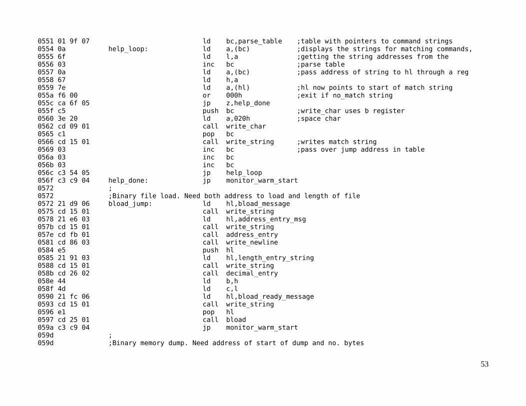
0551 01 9f 07 ld bc,parse_table ;table with pointers to command strings 0554 0a help_loop: ld a,(bc) ;displays the strings for matching commands, 0555 6f ld l,a ;getting the string addresses from the 0556 03 inc bc ;parse table 0557 0a ld a,(bc) ;pass address of string to hl through a reg 0558 67 ld h,a 0559 7e ld a,(hl) ;hl now points to start of match string 055a f6 00 or 000h ;exit if no_match string 055c ca 6f 05 jp z,help_done 055f c5 push bc ;write_char uses b register 0560 3e 20 ld a,020h ;space char 0562 cd 09 01 call write_char 0565 c1 pop bc 0566 cd 15 01 call write_string ;writes match string 0569 03 inc bc ;pass over jump address in table 056a 03 inc bc 056b 03 inc bc 056c c3 54 05 jp help_loop 056f c3 c9 04 help_done: jp monitor_warm_start 0572 ; 0572 ;Binary file load. Need both address to load and length of file 0572 21 d9 06 bload_jump: ld hl,bload_message 0575 cd 15 01 call write_string 0578 21 e6 03 ld hl,address_entry_msg 057b cd 15 01 call write_string 057e cd fb 01 call address_entry 0581 cd 86 03 call write_newline 0584 e5 push hl 0585 21 91 03 ld hl,length_entry_string 0588 cd 15 01 call write_string 058b cd 26 02 call decimal_entry 058e 44 ld b,h 058f 4d ld c,l 0590 21 fc 06 ld hl,bload_ready_message 0593 cd 15 01 call write_string 0596 e1 pop hl 0597 cd 25 01 call bload 059a c3 c9 04 jp monitor_warm_start 059d ; 059d ;Binary memory dump. Need address of start of dump and no. bytes
53

059d 21 20 07 bdump_jump: ld hl,bdump_message 05a0 cd 15 01 call write_string 05a3 21 e6 03 ld hl,address_entry_msg 05a6 cd 15 01 call write_string 05a9 cd fb 01 call address_entry 05ac cd 86 03 call write_newline 05af e5 push hl 05b0 21 ba 03 ld hl,dump_entry_string 05b3 cd 15 01 call write_string 05b6 cd 26 02 call decimal_entry 05b9 44 ld b,h 05ba 4d ld c,l 05bb 21 50 07 ld hl,bdump_ready_message 05be cd 15 01 call write_string 05c1 cd 7c 03 call get_char 05c4 e1 pop hl 05c5 cd 37 01 call bdump 05c8 c3 c9 04 jp monitor_warm_start 05cb ;Prints message for no match to entered command 05cb 21 03 06 no_match_jump: ld hl,no_match_message 05ce cd 15 01 call write_string 05d1 21 88 0f ld hl, buffer 05d4 cd 15 01 call write_string 05d7 c3 c9 04 jp monitor_warm_start 05da ; 05da ;Monitor data structures: 05da ; 05da .. 00 monitor_message: defm "\r\nCPUville Z80 computer, ROM version 7\r\n",0 0603 .. 00 no_match_message: defm "No match found for input string ",0 0624 .. 00 help_message: defm "The following commands are implemented:\r\n",0 064e .. 00 dump_message: defm "Displays a 256-byte block of memory.\r\n",0 0675 .. 00 load_message: defm "Enter hex bytes starting at memory location.\r\n",0 06a4 .. 00 run_message: defm "Will jump to (execute) program at address entered.\r\n",0 06d9 .. 00 bload_message: defm "Loads a binary file into memory.\r\n",0 06fc .. 00 bload_ready_message: defm "\n\rReady to receive, start transfer.",0 0720 .. 00 bdump_message: defm "Dumps binary data from memory to serial port.\r\n",0 0750 .. 00 bdump_ready_message: defm "\n\rReady to send, hit any key to start.",0 0777 ;Strings for matching: 0777 .. 00 dump_string: defm "dump",0 077c .. 00 load_string: defm "load",0
54

0781 .. 00 jump_string: defm "jump",0 0786 .. 00 run_string: defm "run",0 078a .. 00 question_string: defm "?",0 078c .. 00 help_string: defm "help",0 0791 .. 00 bload_string: defm "bload",0 0797 .. 00 bdump_string: defm "bdump",0 079d 00 00 no_match_string: defm 0,0 079f ;Table for matching strings to jumps 079f 77 07 0b 05 7c 07 23 05 parse_table: defw dump_string,dump_jump,load_string,load_jump 07a7 81 07 3b 05 86 07 3b 05 defw jump_string,run_jump,run_string,run_jump 07af 8a 07 4b 05 8c 07 4b 05 defw question_string,help_jump,help_string,help_jump 07b7 91 07 72 05 97 07 9d 05 defw bload_string,bload_jump,bdump_string,bdump_jump 07bf 9d 07 cb 05 defw no_match_string,no_match_jump 07c3 # End of file 2K_ROM_7.asm07c3
55

User Program Listings
# File echo_char_test.asm 0000 ;Program to test serial port. 0000 ;To be entered with ROM Program_loader. 0000 ;Includes port initialization commands 0000 ;When running, should echo typed characters to display. 0000 ;Sends entered characters to output port 0 LEDs also. 0000 org 0800h ;org not really needed, all jumps relative 0800 3e 4e ld a,04eh ;1 stop bit, no parity, 8-bit char, 16x baud 0802 d3 03 out (3),a ;write to control port 0804 3e 37 ld a,037h ;enable receive and transmit 0806 d3 03 out (3),a ;write to control port 0808 db 03 echo_loop_1: in a,(3) ;get status 080a e6 02 and 002h ;check RxRDY bit 080c 28 fa jr z,echo_loop_1 ;not ready, loop 080e db 02 in a,(2) ;get char 0810 d3 00 out (0),a ;data to LEDs 0812 47 ld b,a ;save received char in b reg 0813 db 03 echo_loop_2: in a,(3) ;get status 0815 e6 01 and 001h ;check TxRDY bit 0817 28 fa jr z,echo_loop_2 ;loop if not set 0819 78 ld a,b ;get char back 081a d3 02 out (2),a ;send to output 081c 18 ea jr echo_loop_1 ;start over 081e 081e # End of file echo_char_test.asm 081e
# File boot_loader.asm 0000 ;Minimal boot loader for system with ROM v. 6 and lower. 0000 ;Enter bytes on input port switches using Program_loader. 0000 ;Includes port initialization commands. 0000 ;When runs, will load 256 bytes from serial port into memory at 0900h and jump there. 0000 org 0800h ;org not necessary, all jumps relative 0800 3e 4e ld a,04eh ;1 stop bit, no parity, 8-bit char, 16x baud 0802 d3 03 out (3),a ;write to control port
56

0804 3e 37 ld a,037h ;enable receive and transmit 0806 d3 03 out (3),a ;write to control port 0808 21 00 09 ld hl,0900h ;where to put received code 080b 06 ff ld b,0ffh ;number of bytes to receive 080d db 03 boot_receive_loop: in a,(3) ;get status 080f e6 02 and 002h ;check Rx ready bit 0811 28 fa jr z,boot_receive_loop ;not ready, loop 0813 db 02 in a,(2) ;ready, get byte 0815 77 ld (hl),a ;store in memory 0816 23 inc hl ;point to next location 0817 10 f4 djnz boot_receive_loop ;keep going 0819 c3 00 09 jp 0900h ;done, jump to received code block 081c # End of file boot_loader.asm 081c
# File echo_char.asm 0000 ;Program to test serial port. 0000 ;Binary file can be entered using boot loader. 0000 ;When running, should echo typed characters to display. 0000 ;Sends entered characters to output port 0 LEDs also. 0000 org 0900h 0900 db 03 echo_loop_1: in a,(3) ;get status 0902 d3 01 out (1),a ;status to LEDs 0904 e6 02 and 002h ;check RxRDY bit 0906 ca 00 09 jp z,echo_loop_1 ;not ready, loop 0909 db 02 in a,(2) ;get char 090b d3 00 out (0),a ;data to LEDs 090d 47 ld b,a ;save received char in b reg 090e db 03 echo_loop_2: in a,(3) ;get status 0910 e6 01 and 001h ;check TxRDY bit 0912 ca 0e 09 jp z,echo_loop_2 ;loop if not set 0915 78 ld a,b ;get char back 0916 d3 02 out (2),a ;send to output 0918 c3 00 09 jp echo_loop_1 ;start over 091b 0x00... defs 250,000h ;padding to make sure file is > or = 256 bytes 0a15 # End of file echo_char.asm
57