CPUs Input and output. Supervisor mode, exceptions, traps. Co-processors.
61
CPUs Input and output. Supervisor mode, exceptions, traps. Co-processors.
-
Upload
james-aron-mckinney -
Category
Documents
-
view
236 -
download
5
Transcript of CPUs Input and output. Supervisor mode, exceptions, traps. Co-processors.
CPUs
Input and output. Supervisor mode, exceptions,
traps. Co-processors.
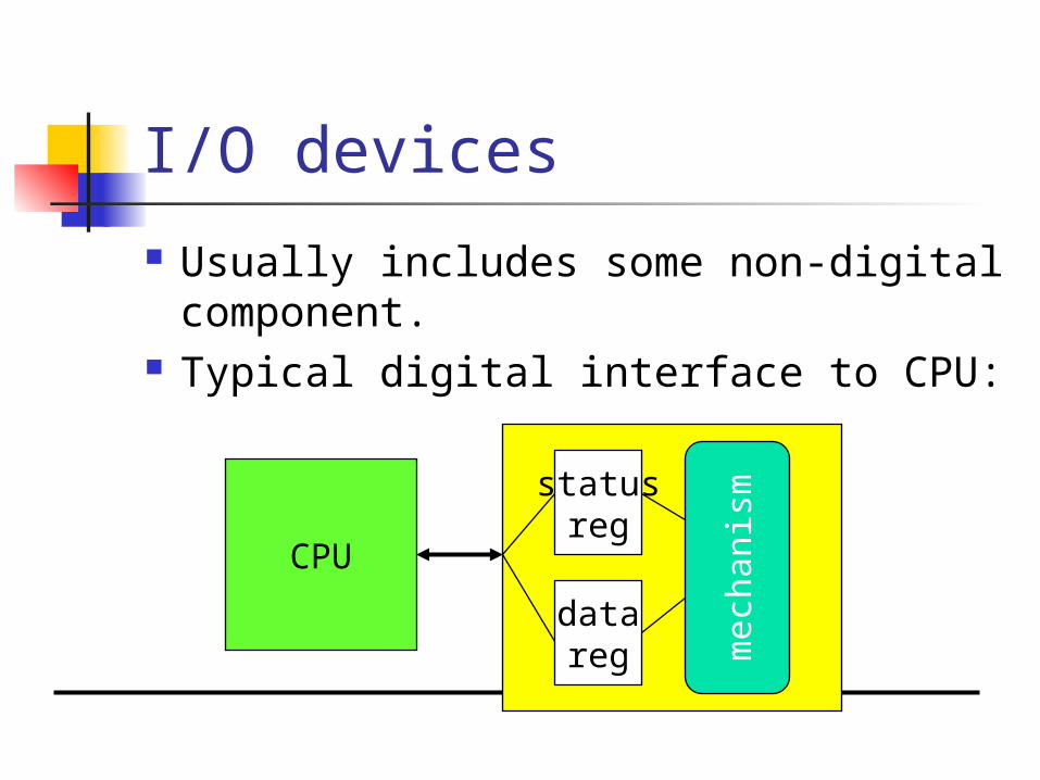
I/O devices
Usually includes some non-digital component.
Typical digital interface to CPU:
CPU
statusreg
datareg
mec
hani
sm

Application: 8251 UART
Universal asynchronous receiver transmitter (UART) : provides serial communication.
8251 functions are integrated into standard PC interface chip.
Allows many communication parameters to be programmed.

Serial communication
Characters are transmitted separately:
time
bit 0 bit 1 bit n-1
nochar
start stop...

Serial communication parameters
Baud (bit) rate. Number of bits per character. Parity/no parity. Even/odd parity. Length of stop bit (1, 1.5, 2 bits).
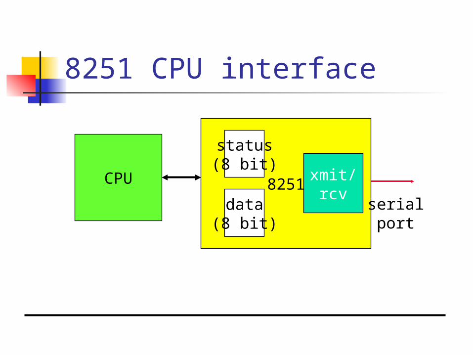
8251 CPU interface
CPU 8251
status(8 bit)
data(8 bit)
serialport
xmit/rcv
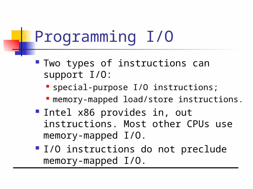
Programming I/O
Two types of instructions can support I/O: special-purpose I/O instructions; memory-mapped load/store instructions.
Intel x86 provides in, out instructions. Most other CPUs use memory-mapped I/O.
I/O instructions do not preclude memory-mapped I/O.
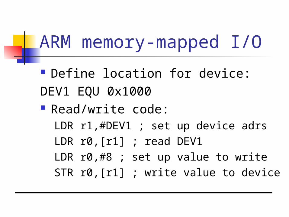
ARM memory-mapped I/O
Define location for device:DEV1 EQU 0x1000 Read/write code:
LDR r1,#DEV1 ; set up device adrsLDR r0,[r1] ; read DEV1LDR r0,#8 ; set up value to writeSTR r0,[r1] ; write value to device

Interrupt I/O
Busy/wait is very inefficient. CPU can’t do other work while testing
device. Hard to do simultaneous I/O.
Interrupts allow a device to change the flow of control in the CPU. Causes subroutine call to handle
device.

Interrupt interface
CPU
statusreg
datareg
mec
hani
sm
PC
intr request
intr ack
data/address
IR
Interrupt behavior
Based on subroutine call mechanism.
Interrupt forces next instruction to be a subroutine call to a predetermined location. Return address is saved to resume
executing foreground program.

Interrupt physical interface
CPU and device are connected by CPU bus.
CPU and device handshake: device asserts interrupt request; CPU asserts interrupt acknowledge
when it can handle the interrupt.

Priorities and vectors
Two mechanisms allow us to make interrupts more specific: Priorities determine what interrupt
gets CPU first. Vectors determine what code is called
for each type of interrupt. Mechanisms are orthogonal: most
CPUs provide both.

Prioritized interrupts
CPU
device 1 device 2 device n
L1 L2 .. Ln
interruptacknowledge

Interrupt prioritization
Masking: interrupt with priority lower than current priority is not recognized until pending interrupt is complete.
Non-maskable interrupt (NMI): highest-priority, never masked. Often used for power-down.
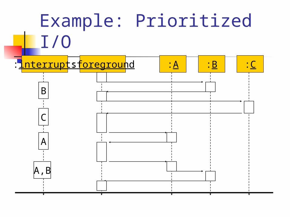
Example: Prioritized I/O:interrupts :foreground :A :B :C
B
A,B
C
A
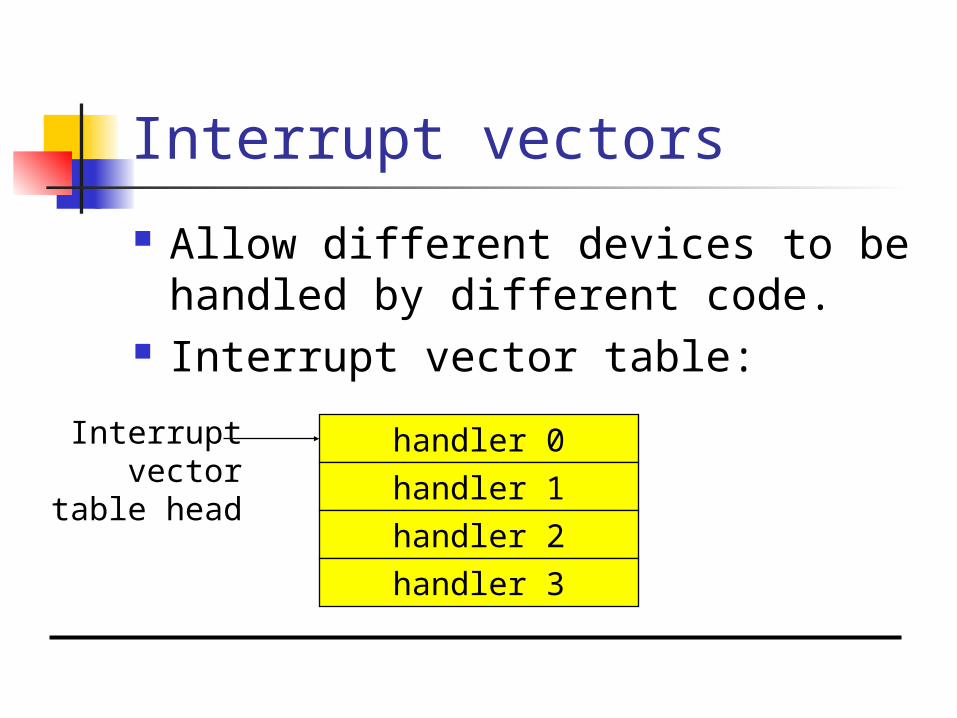
Interrupt vectors
Allow different devices to be handled by different code.
Interrupt vector table:
handler 0
handler 1
handler 2
handler 3
Interruptvector
table head

Interrupt vector acquisition
:CPU :device
receiverequest
receiveack
receivevector

Generic interrupt mechanism
intr?N
YAssume priority selection is
handled before this point.
Nignore
Y
ack
vector?Y
Y
Ntimeout?
Ybus error
call table[vector]
intr priority > current priority?
continueexecution

Interrupt sequence
CPU acknowledges request. Device sends vector. CPU calls handler. Software processes request. CPU restores state to foreground
program.
Sources of interrupt overhead
Handler execution time. Interrupt mechanism overhead. Register save/restore. Pipeline-related penalties. Cache-related penalties.
ARM interrupts
ARM7 supports two types of interrupts: Fast interrupt requests (FIQs). Interrupt requests (IRQs).
Interrupt table starts at location 0.
ARM interrupt procedure
CPU actions: Save PC. Copy CPSR to SPSR. Force bits in CPSR to record interrupt. Force PC to vector.
Handler responsibilities: Restore proper PC. Restore CPSR from SPSR. Clear interrupt disable flags.

ARM interrupt latency
Worst-case latency to respond to interrupt is 27 cycles: Two cycles to synchronize external
request. Up to 20 cycles to complete current
instruction. Three cycles for data abort. Two cycles to enter interrupt handling
state.

Supervisor mode
May want to provide protective barriers between programs. Avoid memory corruption.
Need supervisor mode to manage the various programs.
ARM supervisor mode
Use SWI instruction to enter supervisor mode, similar to subroutine:SWI CODE_1
Sets PC to 0x08. Argument to SWI is passed to
supervisor mode code. Saves CPSR in SPSR.
Exception
Exception: internally detected error. Exceptions are synchronous with
instructions but unpredictable. Build exception mechanism on top
of interrupt mechanism. Exceptions are usually prioritized
and vectorized.

Trap
Trap (software interrupt): an exception generated by an instruction. Call supervisor mode.
ARM uses SWI instruction for traps.

Co-processor
Co-processor: added function unit that is called by instruction. Floating-point units are often
structured as co-processors. ARM allows up to 16 designer-
selected co-processors. Floating-point co-processor uses units
1 and 2.
CPUs
Caches. Memory management.

Caches and CPUs
CPUca
che
cont
roll
er
cache
mainmemory
data
data
address
data
address
Cache operation
Many main memory locations are mapped onto one cache entry.
May have caches for: instructions; data; data + instructions (unified).
Memory access time is no longer deterministic.
Terms
Cache hit: required location is in cache.
Cache miss: required location is not in cache.
Working set: set of locations used by program in a time interval.
Types of misses
Compulsory (cold): location has never been accessed.
Capacity: working set is too large. Conflict: multiple locations in
working set map to same cache entry.

Memory system performance
h = cache hit rate. tcache = cache access time, tmain =
main memory access time. Average memory access time:
tav = htcache + (1-h)tmain
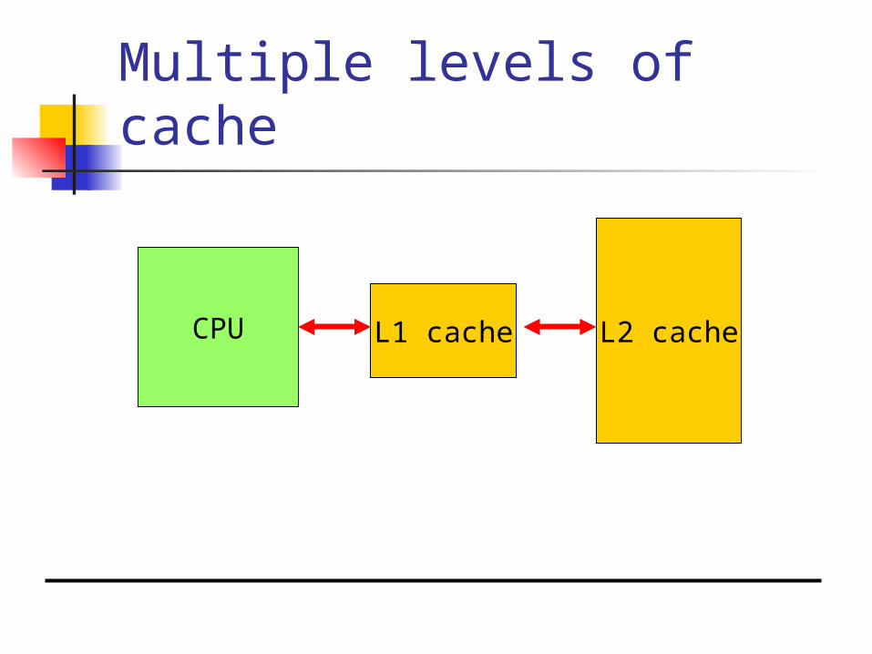
Multiple levels of cache
CPU L1 cache L2 cache

Multi-level cache access time
h1 = cache hit rate. h2 = rate for miss on L1, hit on L2. Average memory access time:
tav = h1tL1 + (h2-h1)tL2 + (1- h2-h1)tmain

Replacement policies
Replacement policy: strategy for choosing which cache entry to throw out to make room for a new memory location.
Two popular strategies: Random. Least-recently used (LRU).
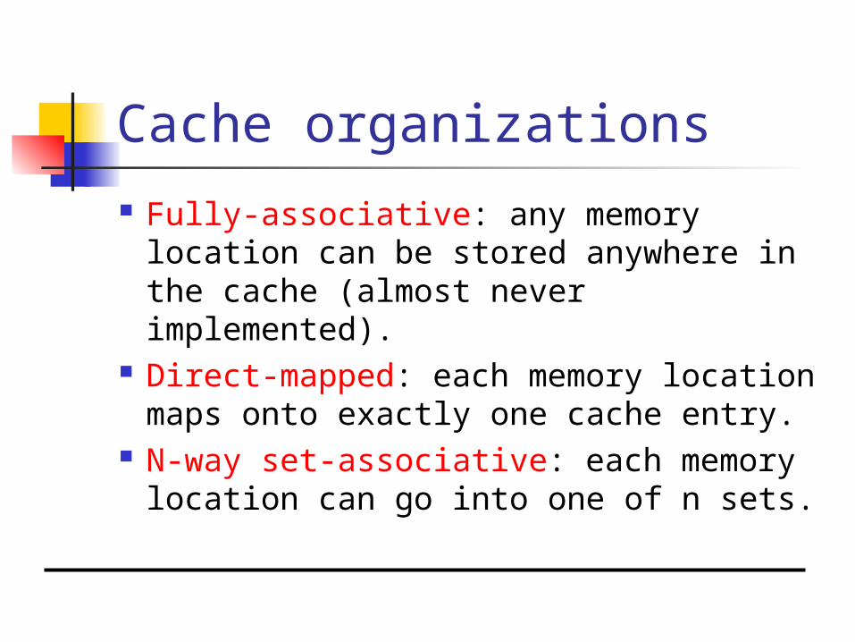
Cache organizations
Fully-associative: any memory location can be stored anywhere in the cache (almost never implemented).
Direct-mapped: each memory location maps onto exactly one cache entry.
N-way set-associative: each memory location can go into one of n sets.
Cache performance benefits
Keep frequently-accessed locations in fast cache.
Cache retrieves more than one word at a time. Sequential accesses are faster after
first access.
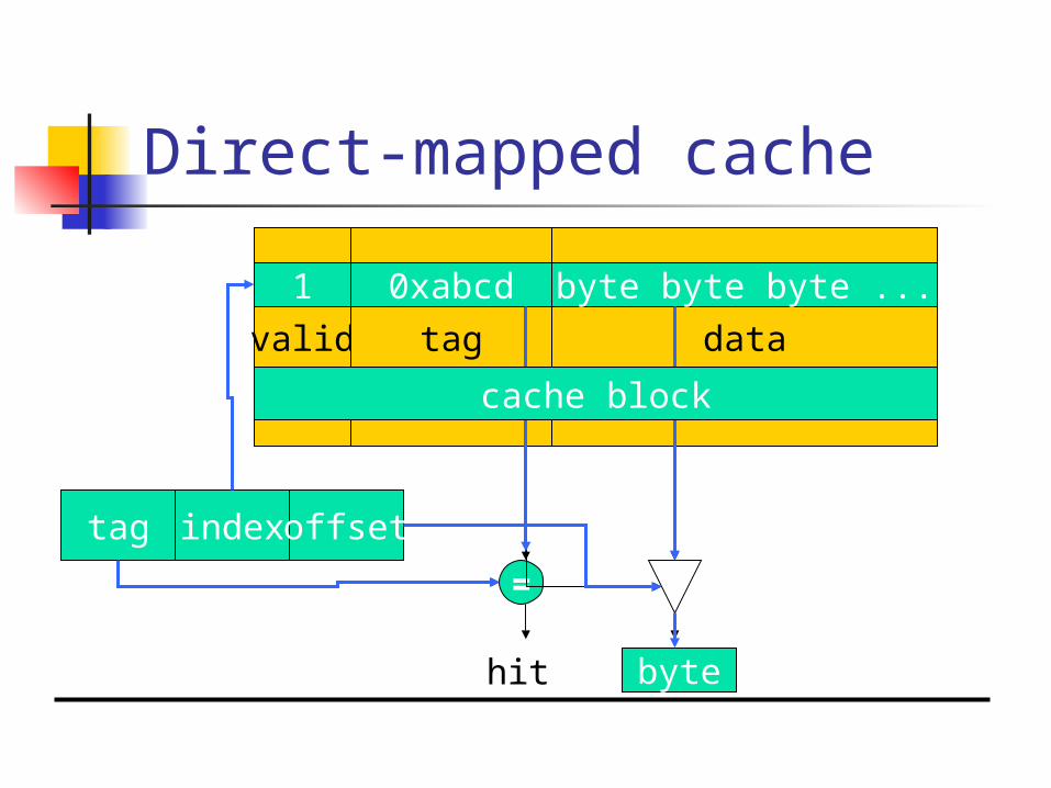
Direct-mapped cache
valid
=
tag index offset
hit value
tag data
1 0xabcd byte byte byte ...
byte
cache block

Write operations
Write-through: immediately copy write to main memory.
Write-back: write to main memory only when location is removed from cache.

Direct-mapped cache locations
Many locations map onto the same cache block.
Conflict misses are easy to generate: Array a[] uses locations 0, 1, 2, … Array b[] uses locations 1024, 1025,
1026, … Operation a[i] + b[i] generates conflict
misses.
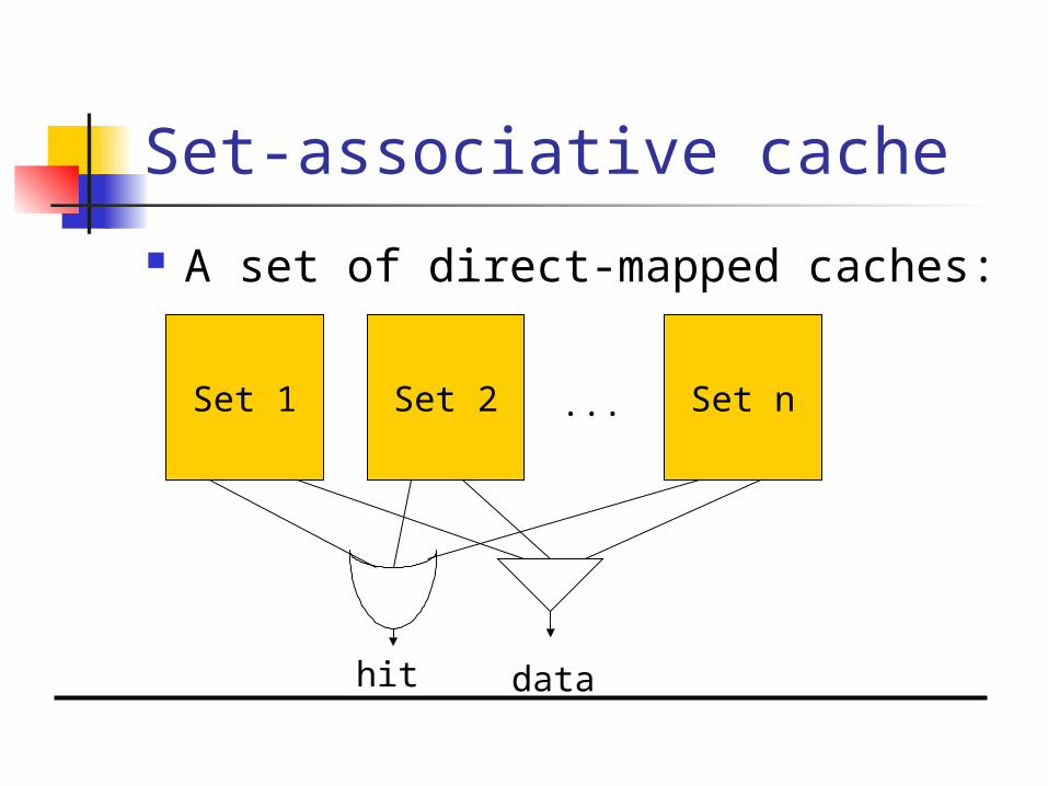
Set-associative cache
A set of direct-mapped caches:
Set 1 Set 2 Set n...
hit data

Example: direct-mapped vs. set-associative
address data000 0101001 1111010 0000011 0110100 1000101 0001110 1010111 0100
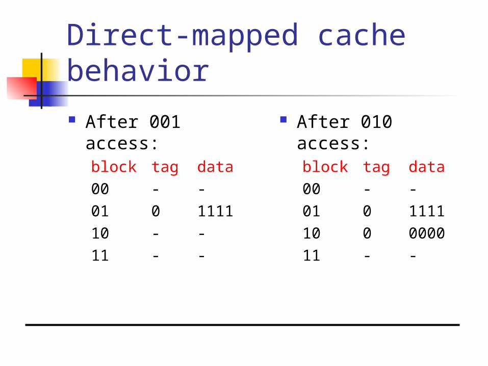
Direct-mapped cache behavior After 001 access:
block tag data00 - -01 0
111110 - -11 - -
After 010 access:block tag data00 - -01 0
111110 0
000011 - -

Direct-mapped cache behavior, cont’d. After 011 access:
block tag data00 - -01 0
111110 0
000011 0
0110
After 100 access:block tag data00 1
100001 0
111110 0
000011 0
0110

Direct-mapped cache behavior, cont’d. After 101 access:
block tag data00 1
100001 1
000110 0
000011 0
0110
After 111 access:block tag data00 1
100001 1
000110 0
000011 1
0100

2-way set-associtive cache behavior
Final state of cache (twice as big as direct-mapped):set blk 0 tag blk 0 data blk 1 tag blk
1 data00 1 1000 - -01 0 1111 1
000110 0 0000 - -11 0 0110 1
0100
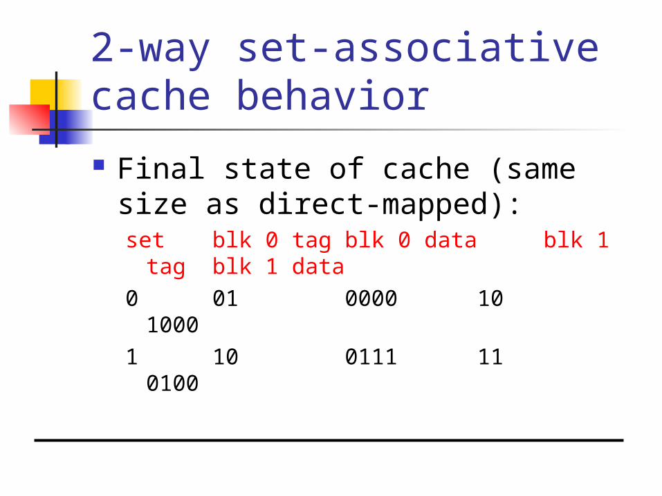
2-way set-associative cache behavior
Final state of cache (same size as direct-mapped):set blk 0 tag blk 0 data blk 1 tag
blk 1 data0 01 0000 10
10001 10 0111 11
0100
Example caches
StrongARM: 16 Kbyte, 32-way, 32-byte block
instruction cache. 16 Kbyte, 32-way, 32-byte block data
cache (write-back).
Memory management units
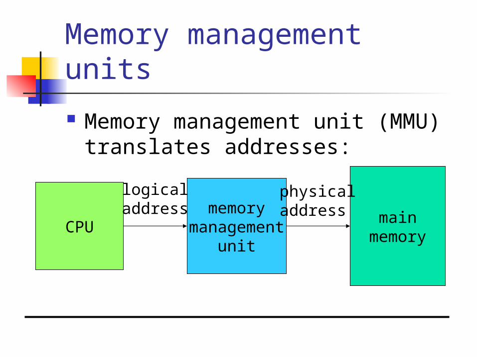
Memory management unit (MMU) translates addresses:
CPUmain
memory
memorymanagement
unit
logicaladdress
physicaladdress
Memory management tasks
Allows programs to move in physical memory during execution.
Allows virtual memory: memory images kept in secondary
storage; images returned to main memory on
demand during execution. Page fault: request for location not
resident in memory.
Address translation
Requires some sort of register/table to allow arbitrary mappings of logical to physical addresses.
Two basic schemes: segmented; paged.
Segmentation and paging can be combined (x86).
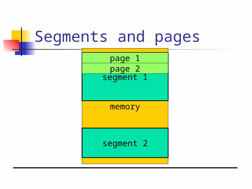
Segments and pages
memory
segment 1
segment 2
page 1page 2

Segment address translation
segment base address logical address
rangecheck
physical address
+
rangeerror
segment lower boundsegment upper bound
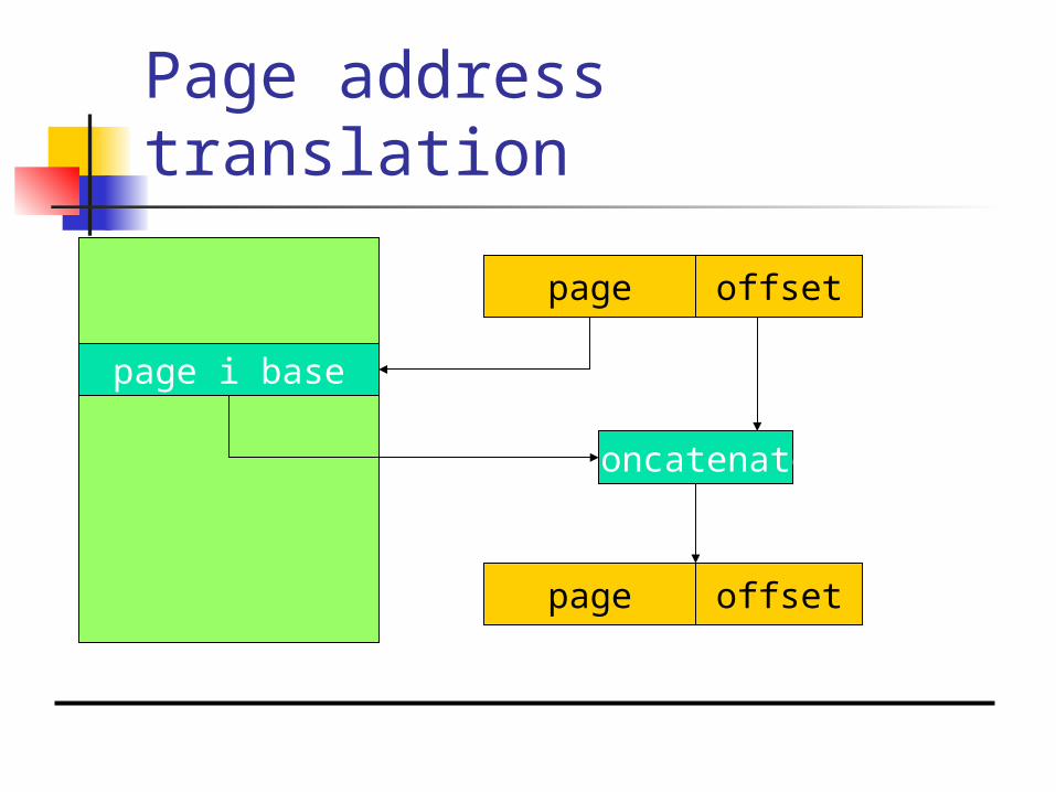
Page address translation
page offset
page offset
page i base
concatenate

Page table organizations
flat tree
page descriptor
pagedescriptor

Caching address translations
Large translation tables require main memory access.
TLB: cache for address translation. Typically small.

ARM memory management
Memory region types: section: 1 Mbyte block; large page: 64 kbytes; small page: 4 kbytes.
An address is marked as section-mapped or page-mapped.
Two-level translation scheme.
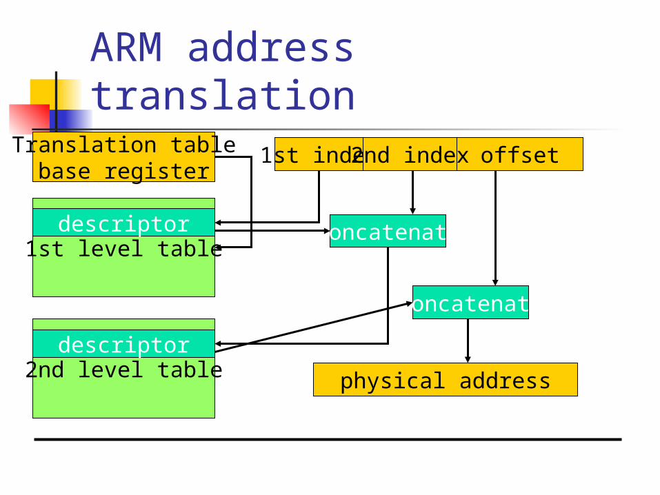
ARM address translationoffset1st index 2nd index
physical address
Translation tablebase register
1st level tabledescriptor
2nd level tabledescriptor
concatenate
concatenate