Agile Is The New Black - Weak vs Strong Agile Processes - Webinar Slides
Agile Processes for Hardware
Development
2
Abstract Hardware and software development are quite different, in terms of the concrete developmental activities. Thus it might seem that Scrum, the Agile process often used for software development, would not be appropriate for hardware development. However, most of the obvious differences between hardware and software development have to do with the nature and sequencing of deliverables, rather than unique attributes of the work that constrain the process. The research conducted for this paper indicates that a Scrum process is quite appropriate for hardware development. Thus this paper describes a practical Agile process for Agile hardware development, which is almost identical to the Scrum process as it is commonly used for developing software.
Acknowledgments
The author would like to thank John Carter (of TCGen) and Dr. Scott Elliott (of TechZecs LLC) for their critical contributions in the areas of hardware development and survey design. This document would not have been possible without their continued participation in every aspect of the research and writing over the last year and a half, including designs for various figures, textual revisions, and numerous proof-readings.
3
Contents 1 Introduction .......................................................................................................................................... 7
2 The Agile Hardware Research Project ................................................................................................. 7
3 Processes for Software Development .................................................................................................. 8
3.1 The Waterfall Process for Software Development ........................................................................ 8
3.2 The Adaptive Spectrum ................................................................ Error! Bookmark not defined.
3.3 Agile Processes for Software Development ................................................................................. 9
3.4 Scrum Time Horizons and Cycles .............................................................................................. 10
4 Hardware vs. Software: Similarities and Differences ......................................................................... 12
4.1 Similarities between Hardware and Software Development ...................................................... 13
4.2 Differences between Hardware and Software Development ..................................................... 13
5 Scrum-Process Customizations for Hardware Development ............................................................. 14
5.1.1 Story Types ......................................................................................................................... 14
5.1.2 Sprint Length ...................................................................................................................... 15
5.1.3 Release Planning ................................................................................................................ 16
5.1.4 Variation in Sprint Focus during a Release Cycle .............................................................. 17
6 Agile Process for Hardware Development ......................................................................................... 18
6.1 Overview ..................................................................................................................................... 19
6.2 Velocity ....................................................................................................................................... 19
6.3 Levels of Governance ................................................................................................................ 20
6.4 Roles ........................................................................................................................................... 20
6.4.1 Project-Level Roles ............................................................................................................. 20
6.4.2 Program-Level Roles .......................................................................................................... 21
6.5 Artifacts ...................................................................................................................................... 22
6.5.1 Product Backlog Items ....................................................................................................... 22
6.5.1.1 User Stories .................................................................................................................... 22
6.5.1.2 Technical Stories ............................................................................................................ 24
6.5.1.3 Defects ........................................................................................................................... 25
6.5.2 Epics ................................................................................................................................... 26
6.5.3 Product Backlog ................................................................................................................. 27
6.5.4 Sprint Backlog .................................................................................................................... 27
4
6.5.5 Definition of Done ............................................................................................................... 27
6.6 Ceremonies ................................................................................................................................ 28
6.6.1 Estimation Concepts ........................................................................................................... 29
6.6.1.1 Units for PBI Estimation .................................................................................................. 29
6.6.1.1.1 Relative Sizing .......................................................................................................... 29
6.6.1.1.2 Absolute Sizing ......................................................................................................... 30
6.6.1.2 How to Estimate Team Velocity ...................................................................................... 30
6.6.1.3 How to Estimate PBIs with Planning Poker ..................................................................... 31
6.6.1.4 How to Estimate Tasks ................................................................................................... 32
6.6.2 Ceremonies for Sprints ....................................................................................................... 32
6.6.2.1 Backlog Grooming Meeting ............................................................................................ 34
6.6.2.2 Sprint Planning Meeting ................................................................................................. 34
6.6.2.2.1 Sprint Planning, Part 1 .............................................................................................. 35
6.6.2.2.2 Sprint Planning, Part 2 .............................................................................................. 35
6.6.2.2.3 How to Allocate Team Members to PBIs .................................................................. 36
6.6.2.3 Daily Stand-Up Meeting ................................................................................................. 37
6.6.2.4 Sprint Review .................................................................................................................. 37
6.6.2.5 Retrospective .................................................................................................................. 38
6.6.3 Ceremonies for Releases ................................................................................................... 39
6.6.3.1 Release Planning ............................................................................................................ 42
6.6.3.1.1 Single Release Planning Meeting ............................................................................. 42
6.6.3.1.2 Incremental Release Planning .................................................................................. 44
6.6.3.1.2.1 Scope Development and Estimation ................................................................. 44
6.6.3.1.2.2 Release Plan Development ............................................................................... 44
6.6.3.1.3 Units for Estimation in Release Planning .................................................................. 44
6.6.3.1.4 How to Estimate PBIs and Epics for Release Planning: Affinity Estimation .............. 45
6.6.4 Scrum-of-Scrums Meeting .................................................................................................. 46
6.6.5 Product Owner Scrum of Scrums Meeting ......................................................................... 46
6.6.6 Release Review .................................................................................................................. 47
6.6.7 Release Retrospective ........................................................................................................ 47
6.7 Tracking and Metrics .................................................................................................................. 48
6.7.1 Tracking Progress for a Sprint ............................................................................................ 48
5
6.7.2 Tracking Progress for a Release ........................................................................................ 49
6.8 How Requirements are Developed ............................................................................................ 50
7 Practical Example of an Agile Hardware Project ............................................................................... 51
7.1 The Project and Product Definition ............................................................................................. 52
7.2 The Team Definitions .................................................................................................................. 52
7.3 Developing High-Level Specifications ....................................................................................... 55
7.4 Developing Detailed Specifications ........................................................................................... 57
7.5 Release Planning ........................................................................................................................ 58
7.5.1 Developing the Release Plan ............................................................................................. 59
7.5.2 The Structure of the Release .............................................................................................. 59
7.6 Regulatory Issues ....................................................................................................................... 61
7.7 How Scope and Work Evolve during the Release Cycle ............................................................ 62
8 Conclusions ........................................................................................................................................ 62
9 Glossary ............................................................................................................................................. 63
6
List of Figures Figure 1: Winston Royce's original Waterfall Diagram ................................................................................. 8 Figure 2: The Five Cycles of Planning in Scrum ......................................................................................... 11 Figure 3: Release-Level View of Concurrent Hardware and Software Development ................................. 19 Figure 4: Sample User Story ...................................................................................................................... 24 Figure 5: Sample Technical Story for Software Development .................................................................... 24 Figure 6: Sample Technical Story for Hardware Development .................................................................. 25 Figure 7: Decomposition of an Epic into PBIs ............................................................................................ 26 Figure 8: A Typical Definition of Done for a Software Team's PBIs ............................................................ 28 Figure 9: A Typical Definition of Done for a Hardware Team's PBIs .......................................................... 28 Figure 10: Typical Sprint Schedule .............................................................. Error! Bookmark not defined.
Figure 11: Typical Release Schedule ........................................................... Error! Bookmark not defined. Figure 12: A Release Plan, as it Appears in the Release Planning Meeting .............................................. 43 Figure 13: An Example of Affinity Estimation .............................................................................................. 46 Figure 14: Scrum Taskboard with Burndown Chart ................................................................................... 49 Figure 15: A Typical Burn-Up Chart ........................................................................................................... 50 Figure 16: Scrum Teams for Cardiac Monitor Development ...................................................................... 54 Figure 17: Network Diagram for Cardiac Monitor Development ................................................................ 56 Figure 18: A Typical Epic for a Major User-Facing Product Capability ..................................................... 56 Figure 19: A Typical Decomposition of Epics into Stories ......................................................................... 58 Figure 20: Structure of the Release Cycle for the Cardiac-Monitor Development ..................................... 61
7
1 Introduction The introduction of Agile processes for software development has brought many advantages to organizations that develop software. Relative to the preceding “Waterfall” approach, these advantages include
• Visibility: Status of work and plans is highly visible, on an hour-by-hour basis • Adaptability: The practice of breaking large scope into many small, testable deliverables has
provided tremendous flexibility to plan, control, and change scope (sometimes dramatically) on short notice
• Minimum time to market: Small, high-value requests can be developed and delivered more quickly, in as little as a few weeks in some cases
• Higher probability of meeting customer needs: More frequent customer testing and feedback allows a better shot at a moving target
Agile processes are not limited to the world of software development. They can be applied in other contexts, such as IT Operations and Production support, where they provide benefits similar to those listed above. This paper addresses how to apply Agile process concepts to the world of hardware development, and integration of hardware and software. “Hardware development” here refers to the development of specifications for devices that are intended to be manufactured. The goal of this paper is to identify practical Agile processes for hardware development.
2 The Agile Hardware Research Project The discoveries presented in this paper derive from a study performed by Dr. Kevin Thompson (cPrime), John Carter (TCGen), and Dr. Scott Elliott (TechZecs) in 2014. The researchers conducted interviews with people at fourteen companies that make hardware, software, or combined products. While none of the companies had a standardized, end-to-end Agile process for hardware development as such, many used some techniques borrowed from the world of Agile software development. For example, we discovered that companies engaged in rapid development of circuit boards through iterative prototyping, division of product-development cycles into time-boxed Sprints, tracking with Burndown charts, and frequent integration and integration testing of components. Our analysis of the research data, including impacts and constraints due to the inherent characteristics of hardware product development, has yielded the insights presented in this paper. The following sections describe the characteristics of hardware development that influence or constrain process definition, and propose an Agile process for hardware development. We begin by looking first at Agile techniques for Software Development, and then identify how hardware development resembles or differs from software development.
8
3 Processes for Software Development The dominant process for software development, up through roughly the year 2000, was the Waterfall process, which was first described by Winston Royce in 1970.1 Although Royce did not coin the term “Waterfall,” he did describe a process whose characteristic stair-step structure and flow inspired the term. Agile processes were developed and introduced in the 1990s, starting with Extreme Programming, and followed a few years later by Scrum. We look at both approaches below.
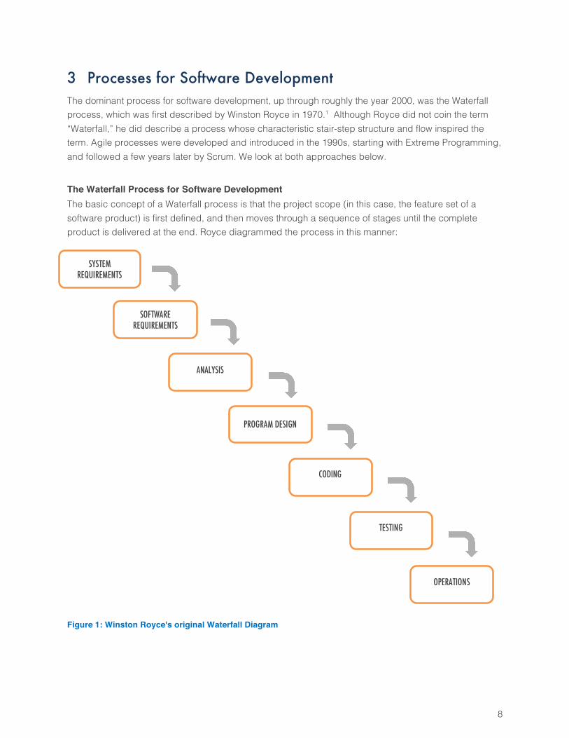
The Waterfall Process for Software Development The basic concept of a Waterfall process is that the project scope (in this case, the feature set of a software product) is first defined, and then moves through a sequence of stages until the complete product is delivered at the end. Royce diagrammed the process in this manner: Figure 1: Winston Royce's original Waterfall Diagram
SYSTEM REQUIREMENTS
SOFTWARE REQUIREMENTS
ANALYSIS
PROGRAM DESIGN
CODING
TESTING
OPERATIONS
9
Royce’s own commentary on this diagram foreshadows the difficulties to come:
“I believe in this concept, but the implementation described above is risky and invites failure. The problem is illustrated in [Royce’s] Figure 4 [Figure 1 above]. The testing phase which occurs at the end of the development cycle is the first event for which timing, storage, input/output transfers, etc., are experienced as distinguished from analyzed. These phenomena are not precisely analyzable. They are not the solutions to the standard partial differential equations of mathematical physics for instance. Yet if these phenomena fail to satisfy the various external constraints, then invariably a major redesign is required. A simple octal patch or redo of some isolated code will not fix these kinds of difficulties. The required design changes are likely to be so disruptive that the software requirements upon which the design is based and which provides the rationale for everything are violated. Either the requirements must be modified, or a substantial change in the design is required. In effect the development process has returned to the origin and one can expect up to a 100-percent overrun in schedule and/or costs.”2
Royce correctly identified the key problem: It is not possible to get the requirements, design, and implementation of a product done exactly the right way in a single pass. Every aspect of software development is subject to such high uncertainty that one cannot simply lay out a plan and follow it, because reality diverges swiftly from the plan. Attempts to reduce uncertainty to the point where one can create a Waterfall-style plan that works are doomed to failure, because the uncertainty cannot be reduced to low levels. The solution to this problem lay almost thirty years in the future, with the development of Agile processes. A core component of this solution is the practice of defining and implementing scope in very small pieces, sequentially, and providing frequent opportunities to correct errors and change direction as understanding of the true needs emerges over time.
Agile Processes for Software Development An Agile process is one that incorporates the principles of the Manifesto for Agile Software Development
(commonly referred to as the Agile Manifesto)3, which states
We are uncovering better ways of developing software by doing it and helping others do it.
Through this work we have come to value:
Individuals and interactions over processes and tools
Working software over comprehensive documentation
Customer collaboration over contract negotiation
Responding to change over following a plan
10
That is, while there is value in the items on the right, we value the items on the left more.
It should be noted that there is nothing inherent in these principles that tie the manifesto to software development in particular, other than the occurrence of the word “software.” Replacing “software” with “product” or “deliverable” retains the philosophy while extending the scope of the Manifesto to a wider world. The Oxford Dictionary4 defines the word “agile” as “Able to move quickly and easily.” For present purposes, a simplified description will suffice for this paper: Agile processes are designed to produce planned deliverables quickly, while adapting well to uncertainty and unexpected changes. Many Agile software-development frameworks or processes have been defined. Some such as Dynamic Systems Development Method (DSDM)5, and Feature Driven Development (FDD)6 are well-defined but are not widely used. Over time, the Agile processes for software development that have become dominant are Scrum7 and Kanban8. Scrum is the process of choice for environments where key drivers include the need to plan work against a calendar, and scale to large, multi-Team environments. Kanban is preferred for environments that are more reactive (i.e., pure bug-fixing or maintenance work), or where there is little need to plan work against a calendar. As schedules are usually important for hardware development work, the lessons from Scrum are more relevant for our purposes.
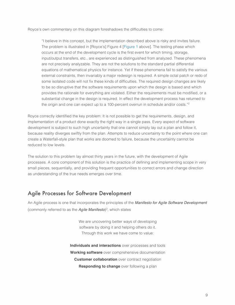
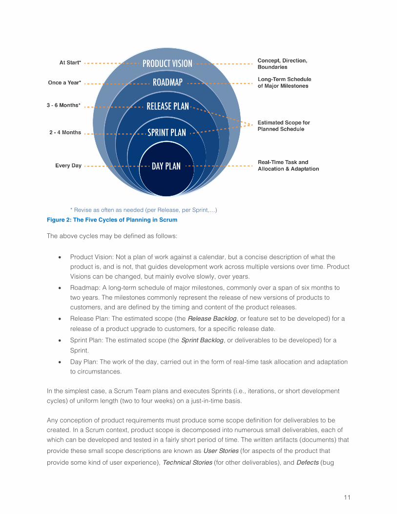
Scrum Time Horizons and Cycles Scrum has neither the flow of a Kanban process, nor the classic plan-driven structure commonly used in construction and many other fields, as exemplified, e.g., by the PMBOK9. Instead, Scrum is a cyclic process. A Scrum process commonly consists of nested cycles that span different time horizons, commonly illustrated as in Figure 2.
11
* Revise as often as needed (per Release, per Sprint,…) Figure 2: The Five Cycles of Planning in Scrum
The above cycles may be defined as follows:
• Product Vision: Not a plan of work against a calendar, but a concise description of what the product is, and is not, that guides development work across multiple versions over time. Product Visions can be changed, but mainly evolve slowly, over years.
• Roadmap: A long-term schedule of major milestones, commonly over a span of six months to two years. The milestones commonly represent the release of new versions of products to customers, and are defined by the timing and content of the product releases.
• Release Plan: The estimated scope (the Release Backlog, or feature set to be developed) for a release of a product upgrade to customers, for a specific release date.
• Sprint Plan: The estimated scope (the Sprint Backlog, or deliverables to be developed) for a Sprint.
• Day Plan: The work of the day, carried out in the form of real-time task allocation and adaptation to circumstances.
In the simplest case, a Scrum Team plans and executes Sprints (i.e., iterations, or short development cycles) of uniform length (two to four weeks) on a just-in-time basis. Any conception of product requirements must produce some scope definition for deliverables to be created. In a Scrum context, product scope is decomposed into numerous small deliverables, each of which can be developed and tested in a fairly short period of time. The written artifacts (documents) that provide these small scope descriptions are known as User Stories (for aspects of the product that
provide some kind of user experience), Technical Stories (for other deliverables), and Defects (bug
12
reports), all of which are discussed in more detail in Section 0. These various artifacts are referred to generically as Product Backlog Items, or PBIs, as they reside within a set or queue of requests called the
Product Backlog prior to scheduling. PBIs should be small, such that roughly 5 to 15 can be started and completed in the same Sprint. This Sprint-level scenario requires that the Scrum Team’s Product Owner develop and rank (sequence)
items in the Product Backlog prior to the Sprint Planning Meeting. The Scrum Master facilitates the Sprint
Planning Meeting, in which the Team members and Product Owner discuss and clarify the PBIs, the Team members estimate the PBIs, and the three Scrum roles collaborate to select an achievable set of PBIs to implement in the Sprint. The Team members decompose the work of each PBI in the new Sprint Backlog into Tasks they will perform, and spend the bulk of the Sprint implementing and validating the deliverables. At the end of the Sprint, they demonstrate the completed deliverables in a Sprint Review
meeting, and capture lessons learned and plan how to improve their process in a Sprint Retrospective meeting. The Scrum Master monitors the progress and process throughout, and focuses on making the Team as productive as possible, by removing obstacles, mentoring the Team, and ensuring that the process is followed. While this minimal scenario is not uncommon, it is far from universal. Organizations of medium to large size may have anywhere from several to several tens of Scrum Teams, whose work must be synchronized to avoid chaos, and for which work must be planned over multiple Sprints in a longer Release cycle. Common techniques for planning and managing cross-Team collaboration and dependencies include Release Planning and Scrum-of-Scrums meetings.
4 Hardware vs. Software: Similarities and Differences In this paper, “hardware” refers specifically to electrical or electro-mechanical devices, which often contain firmware or embedded software. Examples include networking equipment, phones, and other communications technology; consumer electronics; computers; medical devices; ASICs (Application-Specific Integrated Circuits), and so forth. No attempt is made to address specific issues associated with motor vehicles, aircraft, construction equipment, or other products, although much of what is said here will likely have some relevance to those products as well. Similarly, “hardware development” is taken to mean the development of designs for devices that are intended to be manufactured, which excludes the details of the manufacturing process itself (an area that has been addressed in great detail by the principles of Lean Engineering). The following sections describe some key differences between hardware and software development, which have important implications for any effective Agile hardware-development process.

13
Similarities between Hardware and Software Development Software products, hardware products, and combinations of the two in the same product share these characteristics:
• They have behavior: Users interact with the products in various ways, products interact with other products, and products produce outputs given inputs
• They have functional (user-facing) and non-functional (non-user-facing) requirements • They are complex: Any representation of product specifications invariably leads to a tree
structure, as major features are decomposed into finer-grained features
Differences between Hardware and Software Development Software and hardware products differ in these ways:
• Software is more malleable (easier to change) than hardware. The cost of change is much higher for hardware than for software.
• Software products evolve through multiple releases by a process of accretion and refactoring (adding new features and re-writing existing logic to support the new features). Hardware products consist largely of physical components that cannot be “refactored” after manufacturing, and cannot “accrete” new capabilities that require hardware changes. Designs for new hardware products are often based upon earlier-generation products of similar type, but commonly rely on next-generation components that were not present in earlier generations of the product.
• New versions of software and hardware products are both constrained by the design and capabilities of previous versions, but the accretional nature of software development allows for more latitude in deciding what to develop than is the case for hardware. Upgraded versions of hardware products typically have less scope for major qualitative changes, and focus more on quantitative improvements of existing capabilities.
• Hardware designs are constrained by the need to incorporate standard parts. • Specialized hardware components can have much longer lead times for acquisition than is true
for software. • The design for a hardware product is driven in large part by architectural decisions. As the cost
of change is high, more of the architectural work must be done up front compared to software products.
14
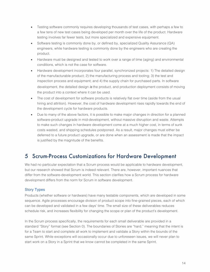
• Testing software commonly requires developing thousands of test cases, with perhaps a few to a few tens of new test cases being developed per month over the life of the product. Hardware testing involves far fewer tests, but more specialized and expensive equipment.
• Software testing is commonly done by, or defined by, specialized Quality Assurance (QA) engineers, while hardware testing is commonly done by the engineers who are creating the product.
• Hardware must be designed and tested to work over a range of time (aging) and environmental conditions, which is not the case for software.
• Hardware development incorporates four parallel, synchronized projects: 1) The detailed design of the manufacturable product; 2) the manufacturing process and tooling; 3) the test and inspection process and equipment; and 4) the supply chain for purchased parts. In software development, the detailed design is the product, and production deployment consists of moving the product into a context where it can be used.
• The cost of development for software products is relatively flat over time (aside from the usual hiring and attrition). However, the cost of hardware development rises rapidly towards the end of the development cycle for hardware products.
• Due to many of the above factors, it is possible to make major changes in direction for a planned software-product upgrade in mid-development, without massive disruption and waste. Attempts to make such changes in hardware development come at a much higher cost, in terms of sunk costs wasted, and shipping schedules postponed. As a result, major changes must either be deferred to a future product upgrade, or are done when an assessment is made that the impact is justified by the magnitude of the benefits.
5 Scrum-Process Customizations for Hardware Development We had no particular expectation that a Scrum process would be applicable to hardware development, but our research showed that Scrum is indeed relevant. There are, however, important nuances that differ from the software-development world. This section clarifies how a Scrum process for hardware development differs from the norm for Scrum in software development.
Story Types Products (whether software or hardware) have many testable components, which are developed in some sequence. Agile processes encourage division of product scope into fine-grained pieces, each of which can be developed and validated in a few days’ time. The small size of these deliverables reduces schedule risk, and increases flexibility for changing the scope or plan of the product’s development. In the Scrum process specifically, the requirements for each small deliverable are provided in a standard “Story” format (see Section 0). The boundaries of Stories are “hard,” meaning that the intent is for a Team to start and complete all work to implement and validate a Story within the bounds of the same Sprint. While exceptions will occasionally occur due to unforeseen issues, we will never plan to start work on a Story in a Sprint that we know cannot be completed in the same Sprint.
15
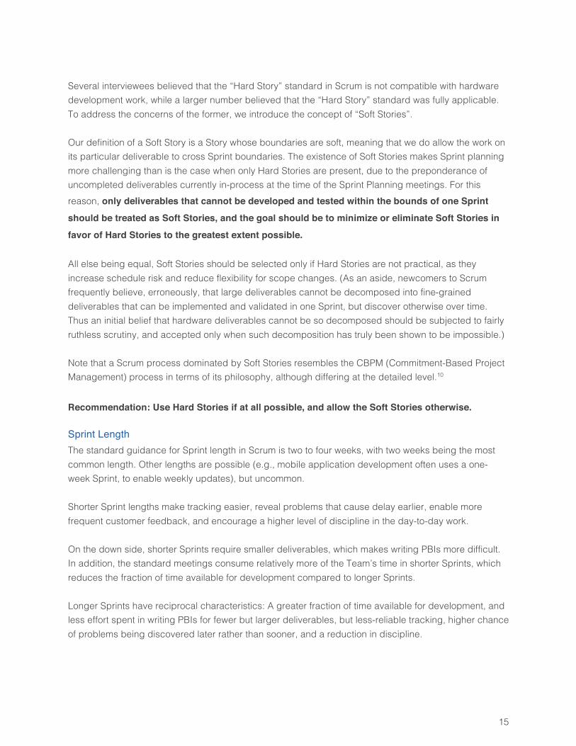
Several interviewees believed that the “Hard Story” standard in Scrum is not compatible with hardware development work, while a larger number believed that the “Hard Story” standard was fully applicable. To address the concerns of the former, we introduce the concept of “Soft Stories”. Our definition of a Soft Story is a Story whose boundaries are soft, meaning that we do allow the work on its particular deliverable to cross Sprint boundaries. The existence of Soft Stories makes Sprint planning more challenging than is the case when only Hard Stories are present, due to the preponderance of uncompleted deliverables currently in-process at the time of the Sprint Planning meetings. For this reason, only deliverables that cannot be developed and tested within the bounds of one Sprint
should be treated as Soft Stories, and the goal should be to minimize or eliminate Soft Stories in
favor of Hard Stories to the greatest extent possible. All else being equal, Soft Stories should be selected only if Hard Stories are not practical, as they increase schedule risk and reduce flexibility for scope changes. (As an aside, newcomers to Scrum frequently believe, erroneously, that large deliverables cannot be decomposed into fine-grained deliverables that can be implemented and validated in one Sprint, but discover otherwise over time. Thus an initial belief that hardware deliverables cannot be so decomposed should be subjected to fairly ruthless scrutiny, and accepted only when such decomposition has truly been shown to be impossible.) Note that a Scrum process dominated by Soft Stories resembles the CBPM (Commitment-Based Project Management) process in terms of its philosophy, although differing at the detailed level.10 Recommendation: Use Hard Stories if at all possible, and allow the Soft Stories otherwise.
Sprint Length The standard guidance for Sprint length in Scrum is two to four weeks, with two weeks being the most common length. Other lengths are possible (e.g., mobile application development often uses a one-week Sprint, to enable weekly updates), but uncommon. Shorter Sprint lengths make tracking easier, reveal problems that cause delay earlier, enable more frequent customer feedback, and encourage a higher level of discipline in the day-to-day work. On the down side, shorter Sprints require smaller deliverables, which makes writing PBIs more difficult. In addition, the standard meetings consume relatively more of the Team’s time in shorter Sprints, which reduces the fraction of time available for development compared to longer Sprints. Longer Sprints have reciprocal characteristics: A greater fraction of time available for development, and less effort spent in writing PBIs for fewer but larger deliverables, but less-reliable tracking, higher chance of problems being discovered later rather than sooner, and a reduction in discipline.
16
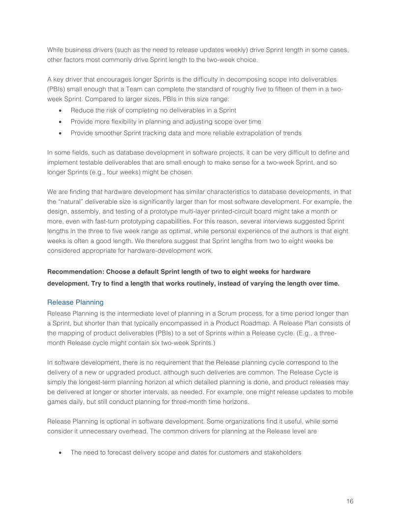
While business drivers (such as the need to release updates weekly) drive Sprint length in some cases, other factors most commonly drive Sprint length to the two-week choice. A key driver that encourages longer Sprints is the difficulty in decomposing scope into deliverables (PBIs) small enough that a Team can complete the standard of roughly five to fifteen of them in a two-week Sprint. Compared to larger sizes, PBIs in this size range:
• Reduce the risk of completing no deliverables in a Sprint • Provide more flexibility in planning and adjusting scope over time • Provide smoother Sprint tracking data and more reliable extrapolation of trends
In some fields, such as database development in software projects, it can be very difficult to define and implement testable deliverables that are small enough to make sense for a two-week Sprint, and so longer Sprints (e.g., four weeks) might be chosen. We are finding that hardware development has similar characteristics to database developments, in that the “natural” deliverable size is significantly larger than for most software development. For example, the design, assembly, and testing of a prototype multi-layer printed-circuit board might take a month or more, even with fast-turn prototyping capabilities. For this reason, several interviews suggested Sprint lengths in the three to five week range as optimal, while personal experience of the authors is that eight weeks is often a good length. We therefore suggest that Sprint lengths from two to eight weeks be considered appropriate for hardware-development work. Recommendation: Choose a default Sprint length of two to eight weeks for hardware
development. Try to find a length that works routinely, instead of varying the length over time.
Release Planning Release Planning is the intermediate level of planning in a Scrum process, for a time period longer than a Sprint, but shorter than that typically encompassed in a Product Roadmap. A Release Plan consists of the mapping of product deliverables (PBIs) to a set of Sprints within a Release cycle. (E.g., a three-month Release cycle might contain six two-week Sprints.) In software development, there is no requirement that the Release planning cycle correspond to the delivery of a new or upgraded product, although such deliveries are common. The Release Cycle is simply the longest-term planning horizon at which detailed planning is done, and product releases may be delivered at longer or shorter intervals, as needed. For example, one might release updates to mobile games daily, but still conduct planning for three-month time horizons. Release Planning is optional in software development. Some organizations find it useful, while some consider it unnecessary overhead. The common drivers for planning at the Release level are
• The need to forecast delivery scope and dates for customers and stakeholders
17
• The need to schedule cross-Team dependencies, to ensure that different Teams’ predecessor deliverables are available for use when needed
Hardware development cannot normally be completed in a time period as short as a Sprint, which means that the Release cycle is the appropriate timeline for product development for hardware, as well as software. However, hardware projects cannot change scope in the middle of a Release cycle as easily as software projects, because of the much higher cost of change for hardware. In addition, the smaller space of design choices available in hardware development means that a Release-level scope definition is likely to be more reliable and stable than is the case for software development. Finally, it is usually necessary to have a reasonable concept of the hardware product as a whole prior to beginning development on it. For all of these reasons, Release Planning is essential for hardware development. It cannot be omitted.
Recommendation: Make Release Planning a standard element of hardware development.
Variation in Sprint Focus during a Release Cycle The type of work done for a software product during a Release cycle is usually very similar from one Sprint to the next. Each Sprint develops a “potentially shippable increment of product functionality,” which means that each Sprint focuses on adding more usable capabilities to the product. The above concept does not hold for hardware projects. Each Sprint does not develop a potentially shippable increment of hardware-product functionality, because hardware development is not accretional. For software products, the flow of deliverables is such that new and usable features appear steadily over time, and these features are aggregated into a newly-released product. For hardware products, the flow of deliverables generally does not produce a steady flow of usable features over time, and the product features become usable late in the development cycle. However, the deliverables can still be developed and tested throughout the cycle, and this is the key point. This point enables the continuing scope adjustment and refinement needed to hit planned shipment dates with the best possible value. The type of work done during a hardware Release cycle may differ significantly across Sprints. Early Sprints in the cycle may focus more on developing the first physical prototype. Later Sprints may focus more on iterating prototypes until the Release objectives have been met. There is no requirement that Sprints have the same focus, and often they will not. The idea that Sprints may be oriented towards different types of work during a Release cycle might be seen as a reversion to a “Waterfall” method, but this is not the case. Waterfall methods rigidly separate requirements development, design, product development, and testing, and suffer from a number of well-known pathologies.
18
The Release cycle described here is not a Waterfall process under another name. Each Sprint implements a set of testable (and validated) set of deliverables, the majority of which represent capabilities of the product. This approach is quite different from a true Waterfall process. Recommendation: Do not introduce more variation in Sprint focus than necessary in a Release cycle, but do allow as much variation as is truly necessary to achieve the Release objectives.
6 Agile Process for Hardware Development The RAGE paper11 introduces a way of describing development processes, including Agile processes, in terms of governance:
Governance is the formalization and exercise of repeatable decision-making
practices
“Governance” is often thought of as being about control, but the RAGE perspective is that control, and other actions, all flow from decisions. If we make decisions well, the rest will follow. Agile Governance is then an Agile style of governance that focuses on rapid decision-making, enabled by lightweight artifacts and simple techniques, using repeatable and standardized practices. If we think of process definition in terms of Agile Governance, we find that they key elements of a process are:
1. Roles: A Role is a set of responsibilities, with corresponding decision-making authority, fulfilled by a person.
2. Ceremonies: A Ceremony is a recurring meeting, with a standard agenda and membership, whose purpose is to make a specific type of decision
3. Artifacts: An artifact is any document, design, chart, or other object developed as part of the process, for the purpose of supporting the work to be done (including decision-making)
4. Tracking and Metrics: Tracking refers to techniques for assessing how the work being accomplished compares the plan, and relates to the goals of the work. Metrics are artifacts (typically, charts, tables, numbers etc.) that provide quantitative information required for effective tracking.
5. Governance Points: A Governance Point is a moment at which someone who fulfills a particular Role makes a decision in the domain of that Role’s authority, based on standard practices, metrics, and artifacts. Many Governance Points are Ceremonies, but many others occur on the fly, as needed.
A particular process is defined by the specifications of its Roles, Ceremonies, Artifacts, Tracking and Metrics, and Governance Points. Each cycle, or time horizon (such as a Sprint or Release cycle) has its
19
own distinct set of these elements. We will propose specifications for these elements below, for the Release and Sprint cycles of a hardware-development process based on Scrum.
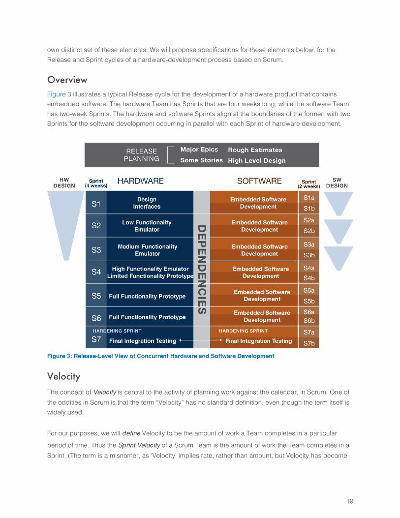
Overview Figure 3 illustrates a typical Release cycle for the development of a hardware product that contains embedded software. The hardware Team has Sprints that are four weeks long, while the software Team has two-week Sprints. The hardware and software Sprints align at the boundaries of the former, with two Sprints for the software development occurring in parallel with each Sprint of hardware development.
Figure 3: Release-Level View of Concurrent Hardware and Software Development
Velocity The concept of Velocity is central to the activity of planning work against the calendar, in Scrum. One of the oddities in Scrum is that the term “Velocity” has no standard definition, even though the term itself is widely used. For our purposes, we will define Velocity to be the amount of work a Team completes in a particular
period of time. Thus the Sprint Velocity of a Scrum Team is the amount of work the Team completes in a Sprint. (The term is a misnomer, as ‘Velocity’ implies rate, rather than amount, but Velocity has become
20
the official term in Scrum and is unlikely to be replaced.) The units for Velocity are the same as the units for the size of PBIs. (See Sections 0 and 0 for details on units and estimation for Velocity.) In a similar vein, we define the Release Velocity of a Scrum Team to be the amount of work the Team completes in a Release cycle. By definition, this Release Velocity is the sum of the Sprint Velocities for the Sprints comprising the Release cycle.
Levels of Governance We define two levels of governance: Project and Program.
• The Project level of governance focuses on the work and practices of individual Scrum Teams.
• The Program level of governance focuses on the coordination of a set of Scrum Teams that must collaborate to develop a product.
Each level of governance has a set of standard Roles and Ceremonies.
Roles A “Role” is a set of responsibilities, and accompanying authority, assigned to and carried out by a person or set of people.
Project-Level Roles The Scrum Roles of Product Owner, Scrum Master, and Team members are clearly defined, as are the responsibilities and areas of authority associated with each: Product Owner: This person has sole authority over product requirements (definition and sequencing), for up to three Teams. Responsibilities include
• Developing and prioritizing all requirements for deliverables (PBIs), user-facing or otherwise, in collaboration with customers, stakeholders, and Team members
• Providing near real-time guidance to Team during implementation and testing of deliverables • Reviewing and approving deliverables
Scrum Master: This person has sole authority over the process, for up to three Teams. A Scrum Master does whatever is needed to make the Team as productive as possible. Scrum Master responsibilities include
• Enforcing the process • Facilitating meetings • Maintaining situational awareness of the work • Knowing Team member strengths and weaknesses • Mentoring the Team
21
• Protecting the Team from interference • Monitoring progress • Removing obstacles, ensuring issues are addressed
Team: This set of people has sole authority over Estimates, Task definitions, and Task assignments. A Team contains three to nine members who do the hands-on work of implementing and validating deliverables. Each Team must include people who validate (test) as well as implement deliverables. It is
never acceptable to have separate Development and Testing teams. Team responsibilities include
• Implementing and validating (testing, fixing) deliverables • Completing work to standard Definition of Done (Section 0)
• Estimating work for deliverables • Allocating tasks within Team (self-organizing) based on skills and availability
Program-Level Roles The Program level adds two Roles beyond the basic Team-level Scrum Roles: The Area Product Owner and the Program Manager. In a small organization, the Role of Product Owner includes both outward (customer) and inward (Team) facing responsibilities. In larger organizations, we split these responsibilities into separate Roles: The Team Product Owner writes User Stories, ranks requirements for a Scrum Team, and monitors the development to ensure that the deliverables are as desired, while the Area Product Owner is responsible for the customer interactions and development of big-picture solutions. Team Product Owner: The sole authority over product requirements (definition and sequencing), for up to three Teams. Responsibilities include
• Writing requirements for implementation by Scrum Teams • Providing near real-time guidance to Team during implementation and testing of deliverables • Reviewing and approving deliverables
Area Product Owner: The sole authority over product requirements for the product, and the intended content of the Release. Responsibilities include
• Working with customers and stakeholders to identify needs, solutions, and business value. • Working with Team Product Owners to develop sufficient detail about requirements and cost
(based on development and testing effort) to support useful Return-on-Investment estimates. • Develop Business Case for Product Releases, for use in Portfolio planning. • Monitor changes in business needs, and work with Team Product Owners to revise the planned
Product Release content as needed.
22
• Provide ongoing guidance to Team Product Owners regarding cross-Team priorities and tradeoffs.
Program Manager: Works closely with Teams’ Scrum Masters or Project Managers to ensure that cross-Team collaboration is effective in achieving the Product’s Release goals. Responsibilities include
• Enforcing agreements on how cross-Team collaboration is done • Facilitating cross-Team meetings • Monitoring cross-Team dependencies, and ensuring that these are planned and addressed
effectively • Assessing impact of development issues and scope changes on cross-Team dependencies and
overall execution • Monitoring progress of the Product Release • Ensuring that risks are addressed effectively during planning and execution • Removing obstacles to effective cross-Team collaboration
Artifacts The following artifacts are widely used in Scrum.
Product Backlog Items A Product Backlog Item (PBI) is a specification for a deliverable that one Team can implement in a modest fraction of a Sprint. (We recommend that no one PBI exceed one third of a Team’s Sprint Velocity.) The Scrum world does not have a standardized conception or format for PBIs. There is general agreement that User Stories should be used, less agreement about the fine details of how to write a User Story, and no general agreement on other Backlog artifacts. We will define three types of Product Backlog Items, namely User Stories, Technical Stories, and Defects. User Stories describe users’ experience of product features, Technical Stories describe deliverables that are not user facing, and Defects are bug reports.
User Stories
A User Story is a short narrative description of some aspect of a product’s functionality that a user experiences. A User Story describes the user’s interaction with the product, in a brief format that conveys a basic understanding without attempting to spell out all of the details. User Stories are most often written by Product Owners, who act as proxies for the actual users. The term “User” refers to a category of person who experiences the deliverable in some fashion. Many types of user experience are possible, such as
• A Doctor uses a cardiac monitor to view an electrocardiogram • A Firefighter selects a communication channel on a portable radio • A Developer calls hardware functions through a supplied programmatic interface
23
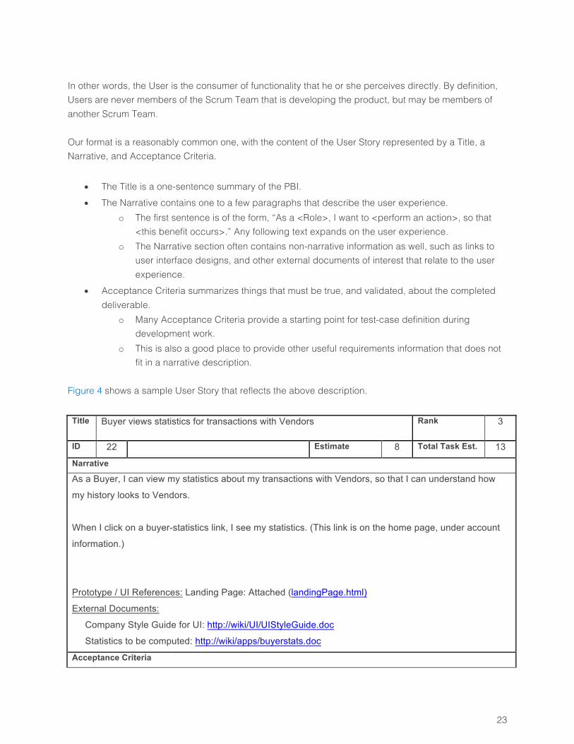
In other words, the User is the consumer of functionality that he or she perceives directly. By definition, Users are never members of the Scrum Team that is developing the product, but may be members of another Scrum Team. Our format is a reasonably common one, with the content of the User Story represented by a Title, a Narrative, and Acceptance Criteria.
• The Title is a one-sentence summary of the PBI. • The Narrative contains one to a few paragraphs that describe the user experience.
o The first sentence is of the form, “As a <Role>, I want to <perform an action>, so that <this benefit occurs>.” Any following text expands on the user experience.
o The Narrative section often contains non-narrative information as well, such as links to user interface designs, and other external documents of interest that relate to the user experience.
• Acceptance Criteria summarizes things that must be true, and validated, about the completed deliverable.
o Many Acceptance Criteria provide a starting point for test-case definition during development work.
o This is also a good place to provide other useful requirements information that does not fit in a narrative description.
Figure 4 shows a sample User Story that reflects the above description. Title Buyer views statistics for transactions with Vendors Rank 3
ID 22 Estimate 8 Total Task Est. 13
Narrative
As a Buyer, I can view my statistics about my transactions with Vendors, so that I can understand how
my history looks to Vendors.
When I click on a buyer-statistics link, I see my statistics. (This link is on the home page, under account
information.)
Prototype / UI References: Landing Page: Attached (landingPage.html)
External Documents:
Company Style Guide for UI: http://wiki/UI/UIStyleGuide.doc
Statistics to be computed: http://wiki/apps/buyerstats.doc
Acceptance Criteria
24
• When the user clicks on the link, the application should display the statistics.
• User can create fictitious buyers and suppliers for use in testing.
• When the user submits or responds to RFPs, report shows updated statistics that reflect the
user’s activities.
• The screen should appear within one second, under a load of 20 concurrent requests pulling data
from 20 different static-content files.
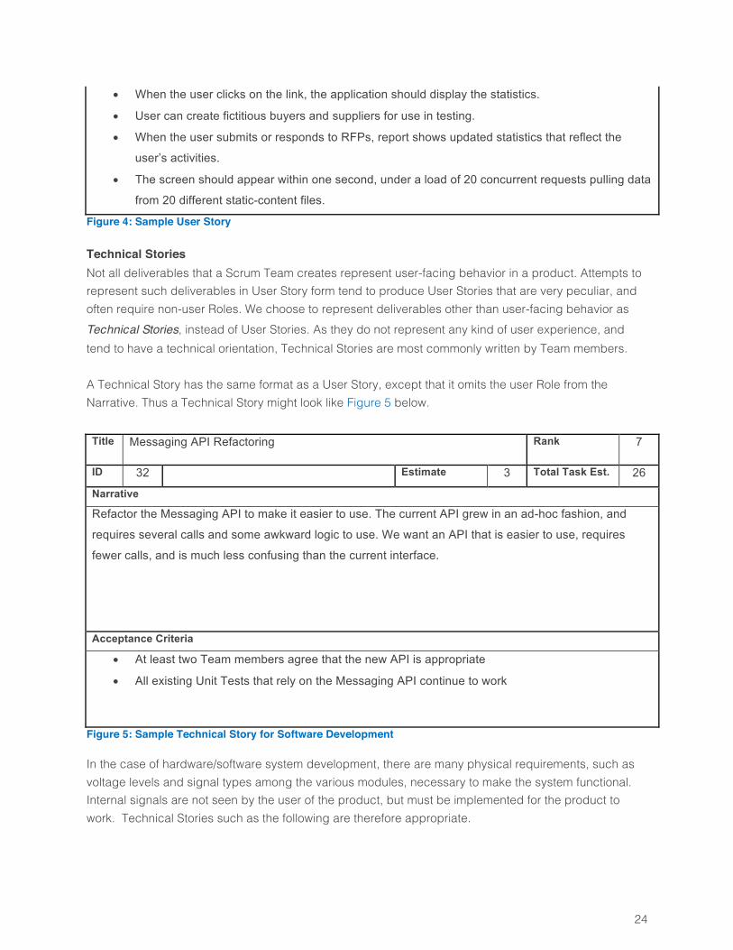
Figure 4: Sample User Story
Technical Stories Not all deliverables that a Scrum Team creates represent user-facing behavior in a product. Attempts to represent such deliverables in User Story form tend to produce User Stories that are very peculiar, and often require non-user Roles. We choose to represent deliverables other than user-facing behavior as Technical Stories, instead of User Stories. As they do not represent any kind of user experience, and tend to have a technical orientation, Technical Stories are most commonly written by Team members. A Technical Story has the same format as a User Story, except that it omits the user Role from the Narrative. Thus a Technical Story might look like Figure 5 below. Title Messaging API Refactoring Rank 7
ID 32 Estimate 3 Total Task Est. 26
Narrative
Refactor the Messaging API to make it easier to use. The current API grew in an ad-hoc fashion, and
requires several calls and some awkward logic to use. We want an API that is easier to use, requires
fewer calls, and is much less confusing than the current interface.
Acceptance Criteria
• At least two Team members agree that the new API is appropriate
• All existing Unit Tests that rely on the Messaging API continue to work
Figure 5: Sample Technical Story for Software Development
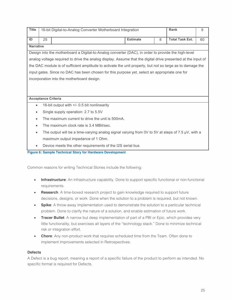
In the case of hardware/software system development, there are many physical requirements, such as voltage levels and signal types among the various modules, necessary to make the system functional. Internal signals are not seen by the user of the product, but must be implemented for the product to work. Technical Stories such as the following are therefore appropriate.
25
Title 16-bit Digital-to-Analog Converter Motherboard Integration Rank 9
ID 25 Estimate 8 Total Task Est. 60
Narrative
Design into the motherboard a Digital-to-Analog converter (DAC), in order to provide the high-level
analog voltage required to drive the analog display. Assume that the digital drive presented at the input of
the DAC module is of sufficient amplitude to activate the unit properly, but not so large as to damage the
input gates. Since no DAC has been chosen for this purpose yet, select an appropriate one for
incorporation into the motherboard design.
Acceptance Criteria
• 16-bit output with +/- 0.5 bit nonlinearity
• Single supply operation: 2.7 to 5.5V
• The maximum current to drive the unit is 500mA.
• The maximum clock rate is 3.4 MBit/sec.
• The output will be a time-varying analog signal varying from 0V to 5V at steps of 7.5 µV, with a
maximum output impedance of 1 Ohm.
• Device meets the other requirements of the I2S serial bus
Figure 6: Sample Technical Story for Hardware Development
Common reasons for writing Technical Stories include the following:
• Infrastructure: An infrastructure capability. Done to support specific functional or non-functional requirements.
• Research: A time-boxed research project to gain knowledge required to support future decisions, designs, or work. Done when the solution to a problem is required, but not known.
• Spike: A throw-away implementation used to demonstrate the solution to a particular technical problem. Done to clarify the nature of a solution, and enable estimation of future work.
• Tracer Bullet: A narrow but deep implementation of part of a PBI or Epic, which provides very little functionality, but exercises all layers of the “technology stack.” Done to minimize technical risk or integration effort.
• Chore: Any non-product work that requires scheduled time from the Team. Often done to implement improvements selected in Retrospectives.
Defects A Defect is a bug report, meaning a report of a specific failure of the product to perform as intended. No specific format is required for Defects.
26
Defects are commonly reported by users of the product, and most commonly enter the Product Backlog via reports from Technical Support personnel. Defects are ranked alongside other PBIs, with the ranking based on the value of fixing the bug. Team members (including development and Quality Assurance experts) usually do not enter Defects into the Product Backlog for problems found in Stories that are currently in process, when there is no need to retain a record of such problems beyond the lifespan of the Story. (Defects that do require such tracking should, of course, be captured.) Defects found in other parts of the product, in the course of normal work, may of course be reported and entered into the Product Backlog.
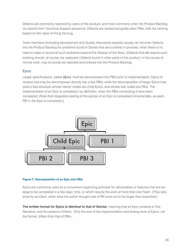
Epics Larger specifications, called Epics, must be decomposed into PBIs prior to implementation. Epics of modest size may be decomposed directly into a few PBIs, while the decomposition of larger Epics may yield a tree structure whose interior nodes are child Epics, and whose leaf nodes are PBIs. The implementation of an Epic is completed, by definition, when the PBIs comprising it have been completed. (Note that integration-testing of the pieces of an Epic is completed incrementally, as each PBI in the Epic is completed.)
Figure 7: Decomposition of an Epic into PBIs
Epics are commonly used as a convenient organizing principle for deliverables or features that are too large to be completed in a few days’ time, or which require the work of more than one Team. (They also arise by accident, when what the author thought was a PBI turns out to be larger than expected.) The written format for Epics is identical to that of Stories, meaning that an Epic contains a Title, Narrative, and Acceptance Criteria. Only the size of the implementation and testing work of Epics, not the format, differs from that of PBIs.
Epic
Child Epic
PBI 2 PBI 3
PBI 1
27
It is acceptable, but not usually necessary, to refer to “User Epics” and “Technical Epics.” In these cases, “User” and “Technical” refer to the focus of the Epic, but there is no assumption that a User Epic cannot contain a Technical Story, and vice versa. In fact, each type of Epic very often will contain the other type of Story. Many Epics that are primarily about user-facing behavior involve multiple Roles, and cannot be written in a fashion that involves a single Role performing an Action. In this case, the Narrative still describes a user experience, but that experience may involve multiple Roles, explicitly or implicitly.
Product Backlog The Product Backlog is the set of requirements developed for a specific Team, which have not yet been assigned to a particular Sprint for implementation. The Product Backlog is often thought of as having two parts. The top part has PBIs listed in rank order, as required to support upcoming planning work. The bottom part contains all other PBIs, for which ranking is not yet necessary, and would often be a waste of time. Technically, Epics are not part of a Product Backlog, as Epics are not implemented directly, and many Agile project-management tools do manage them separately from Product Backlogs. However, in casual conversation, Epics are often spoken of as if they were elements in a Product Backlog, especially when they are treated as placeholders for PBIs that have not yet been written (i.e., the Epic has not yet been decomposed into PBIs).
Sprint Backlog The Sprint Backlog is the ranked sequence of Product Backlog Items (Stories and Defects) assigned to a particular Sprint, for implementation by a particular Team. During Sprint Planning, items are moved from the Product Backlog into the Sprint Backlog. After a Sprint has been completed, the Sprint Backlog for that Sprint is the set of all Product Backlog Items that were completed, which may not be the same as what was planned.
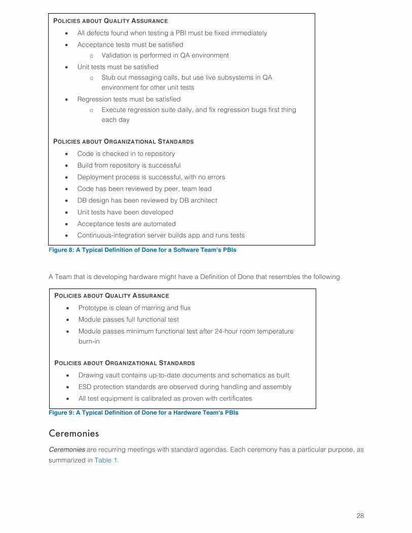
Definition of Done The Definition of Done clarifies and standardizes the Team’s understanding of what must be accomplished in the course of creating each deliverable (as described in its PBI), testing the deliverable, and fixing defects found in it. It contains a set of policy statements regarding how quality is assured, and how organizational standards are met. Figure 8 shows a typical set of such policies for a software development Team.
28
Figure 8: A Typical Definition of Done for a Software Team's PBIs
A Team that is developing hardware might have a Definition of Done that resembles the following.
Figure 9: A Typical Definition of Done for a Hardware Team's PBIs
Ceremonies Ceremonies are recurring meetings with standard agendas. Each ceremony has a particular purpose, as summarized in Table 1.
POLICIES ABOUT QUALITY ASSURANCE
• All defects found when testing a PBI must be fixed immediately • Acceptance tests must be satisfied
o Validation is performed in QA environment • Unit tests must be satisfied
o Stub out messaging calls, but use live subsystems in QA environment for other unit tests
• Regression tests must be satisfied o Execute regression suite daily, and fix regression bugs first thing
each day POLICIES ABOUT ORGANIZATIONAL STANDARDS
• Code is checked in to repository • Build from repository is successful • Deployment process is successful, with no errors • Code has been reviewed by peer, team lead • DB design has been reviewed by DB architect • Unit tests have been developed • Acceptance tests are automated • Continuous-integration server builds app and runs tests
POLICIES ABOUT QUALITY ASSURANCE
• Prototype is clean of marring and flux • Module passes full functional test • Module passes minimum functional test after 24-hour room temperature
burn-in POLICIES ABOUT ORGANIZATIONAL STANDARDS
• Drawing vault contains up-to-date documents and schematics as built • ESD protection standards are observed during handling and assembly • All test equipment is calibrated as proven with certificates
29
Ceremonies are associated with specific time horizons, or cycles. The ceremonies for Releases are different from those of Sprints, although similar in nature. In the following sections, we look at estimation techniques used in these Ceremonies, and then the Ceremonies themselves.
Estimation Concepts Any process that plans work against a calendar involves some concept of work estimates, and Scrum is no exception. In this section we look at items that require estimation, and techniques for estimating them.
Units for PBI Estimation The purpose of estimation is to enable planning of work over time, on some kind of calendar. Any units that achieve this purpose will suffice. The categories of units commonly used for estimating PBIs may be described as relative sizing and
absolute sizing. Other units are possible, but seldom encountered.
Relative Sizing In relative sizing, the units are called Story Points. Story Points do not relate directly to time or any measurable attribute of the PBI. Instead, Story Points are defined by association with a set of reference PBIs. Prior to its first Sprint, a new Team reviews a set of PBIs, identifies a small one, and arbitrarily assigns it a small size, such as “two Story Points.” The Team then identifies smaller and larger ones, and assigns them sizes of “one Story Point” and “three Story Points,” respectively. The team next conducts a triangulation assessment for the validity of the scale, by asking three questions:
1. Is the 2 SP PBI twice the size of the 1 SP PBI? 2. Is the 3 SP PBI three times the size of the 1 SP PBI? 3. Is the 3 SP PBI one and a half times the size of the 2 SP PB?
If all three questions have a “Yes” answer, the PBIs size is scaling consistently with the numbers. If any question has a “No” answer, the Team goes through the process again until they do identify a consistent set. They then continue in this fashion to identify reference PBIs to associate with other allowed numbers (e.g., the Fibonacci sequence, with 5, 8, 13, … for the larger numbers). Having established this reference scale, future PBIs are estimated by comparison with the reference items. For example, a Team might say, “This item has a size of five Story Points, because we believe it is closer in size to our reference item of that size than it is to any of the other reference items.” While Story Points are not defined in terms of time, the practical reality is that a Scrum Team should be completing roughly five to fifteen PBIs per Sprint . This reality does constrain the meaning of a Story
30
Point, with the result that a one Story-Point PBI usually does not take more than a day or two to complete, in the absence of interruptions.
Absolute Sizing
In absolute sizing, the units define an amount of effort, which is the aggregated time spent by all people who work on a PBI. The name of the unit is “Person Day” (sometimes referred to as “Man Day”). For example, a PBI that requires eight hours of work by one person has a size of one Person Day, as does a PBI that requires four hours of work from each of two people. The effort required to complete a PBI does not map directly to the duration of the work. A PBI with a size of one Person Day will often require two or three calendar days to complete, because the eight hours of work will not be done in a single eight-hour span of time. Or it might require less than eight hours on the clock, if two or three people work on it in parallel. Thus it is important to understand the distinction between effort and duration, as the most common failure mode for absolute sizing is to estimate duration in calendar days. Only effort matters, for estimation purposes. Duration is irrelevant. The distinction between relative and absolute sizing can blur over time. Teams that choose absolute sizing can define reference Stories for different sizes, and use the style of thinking employed in relative sizing while still yielding time-based estimates.
How to Estimate Team Velocity
We define the Velocity of a Scrum Team to be the amount of work the Team completes in a Sprint (as per Section 0). The Velocity for a completed Sprint is computed as the sum of the estimates for the PBIs completed in that Sprint. (By convention, PBIs that were started but not completed in the Sprint do not contribute to that Sprint’s Velocity. They will contribute to the Velocity of the Sprint in which they are completed.) Over time, a Team develops a history of Velocity values that may be used to forecast the Velocity of future Sprints. The process of Sprint planning requires some estimate of the Velocity expected for the Sprint, which is used to bound the scope of work for the Sprint. Thus the Scrum Master must provide a forecast of the Team’s Velocity prior to the Sprint Planning meeting. Many techniques for estimating Velocity exist, and none is mandated. Possibilities includes estimating Velocity as
1. The observed Velocity for the last Sprint 2. A running average of the last three Sprints’ observed Velocities 3. (Team size) x (# days in Sprint) x (focus factor), where “focus factor” is the fraction of time a
Team spends developing and testing PBIs in a Sprint (e.g., 60%) 4. The sum of the times Team members are available to work on PBIs in the Sprint, based on
meeting schedules and individual availability for Sprint work
31
The first two methods may be used in the context of relative sizing, while all four may be used in the context of absolute sizing. There is no “right” way to estimate Velocity, and other variations on the above techniques are also valid. The fourth method is generally the most reliable for absolute sizing, and also the most work to perform. The third is adequate if Team size and personal availability is consistent from one Sprint to the next, so that one can determine a standard focus factor value (e.g., 50%) that yields reliable predictions. The first two are obviously easier, but do not deal well with individual schedule variations.
How to Estimate PBIs with Planning Poker A Scrum Team may use any estimation technique that works for them, but we recommend Planning Poker12 specifically. With the Planning Poker technique, each Team Member is given a deck of cards, printed with numbers such as 0, ½, 1, 2, 3, 5, 8, 13, and so forth. Most card decks used for Planning Poker are based at least approximately on the Fibonacci sequence. The logic behind this selection is that we want values that are spaced far enough apart to be clearly distinct. For example, the difference between 1 and 2 is large (a factor of two), while the difference between 10 and 11 is small (ten percent). A deck that contains closely-spaced numbers will lead to time-wasting discussions between numbers that are closer to each other than either is likely to be to the actual value to be estimated. Hence we use a relatively coarse scale, such as the Fibonacci sequence, for which numbers increase by around 50% from one to the next. At the time of the estimation session, it is assumed that Team Members are already familiar with the PBI based on previous discussions. The Scrum Master normally facilitates the estimation process, during which the Team members commonly estimate a number of PBIs. The Product Owner reads the current PBI to the Team, and spends a few minutes answering any questions they have. The Scrum Master asks that each Team members pick a card with his/her estimate, and hide the card. When all Team members have selected cards, the Scrum Master asks them to show their cards, and then asks the low and high voters to explain the reasoning behind their numbers. The group then has a brief discussion to clarify and resolve issues and questions resulting from the vote, and re-votes. A third vote is often useful for achieving consensus, but additional rounds of voting are not usually productive. If Team members stabilize at a small range of values, they should discuss the values and agree on a consensus number. If the numbers are far apart and do not converge, it is likely that the PBI is poorly written and poorly understood, and its estimation should be deferred until it is rewritten. The participants continue in this fashion until they have estimated enough PBIs for their current purpose (most commonly, enough to fill a Sprint). The Planning Poker technique offers two key benefits:
32
• It minimizes anchoring, i.e. the tendency for a Team to adopt a consensus belief driven by the
influence of a single person, who is often perceived as the expert. • It produces a dramatic improvement in the Team’s consensus understanding of what the
deliverable is, and what must be done to produce it The estimate for a PBI must encompass all work required to implement and validate the PBI’s deliverables according to the Team’s Definition of Done (Section 0). This effort includes development work, testing work, and any other kind of work involved.
How to Estimate Tasks Task estimates are always provided with units of hours, which denote the effort required to execute them. Tasks are both more numerous than, and simpler than, PBIs. Because they are numerous, their estimation via Planning Poker would normally take an impractical amount of time. Because they are simpler than PBIs, anchoring is less of an issue, and it usually suffices for Team members to come up with a consensus estimate of Task hours through informal discussion. Since Planning Poker is not used, there is no restriction on the possible numbers, which need not correspond to the values in a Planning-Poker card deck. Values such as ½, or any integer in the allowed range, are acceptable.
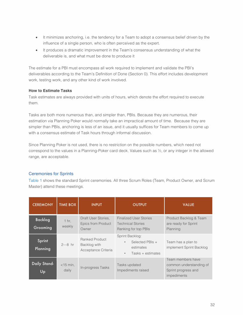
Ceremonies for Sprints Table 1 shows the standard Sprint ceremonies. All three Scrum Roles (Team, Product Owner, and Scrum Master) attend these meetings.
CEREMONY TIME BOX INPUT OUTPUT VALUE
Backlog
Grooming
1 hr, weekly
Draft User Stories, Epics from Product Owner
Finalized User Stories Technical Stories Ranking for top PBIs
Product Backlog & Team are ready for Sprint Planning
Sprint
Planning 2—8 hr
Ranked Product Backlog with Acceptance Criteria
Sprint Backlog: • Selected PBIs +
estimates • Tasks + estimates
Team has a plan to implement Sprint Backlog
Daily Stand-
Up
<15 min, daily
In-progress Tasks Tasks updated Impediments raised
Team members have common understanding of Sprint progress and impediments
33
Sprint
Review < 1 hr
Demo prepared for completed PBIs
New PBIs, based on review by Product Owner Ranking may be revised
Deliverables reviewed; feedback from stake-holders, other teams
Retrospective 1—1.5 hr Sprint performance data, e.g. Burndown chart
Short list of improvements for next Sprint, with owners
Learn from experience, enable continuous improvement
Table 1: Scrum Ceremonies for a Sprint
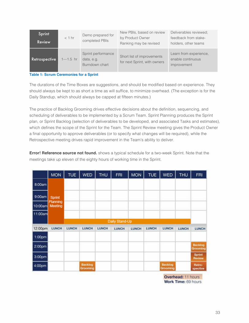
The durations of the Time Boxes are suggestions, and should be modified based on experience. They should always be kept to as short a time as will suffice, to minimize overhead. (The exception is for the Daily Standup, which should always be capped at fifteen minutes.) The practice of Backlog Grooming drives effective decisions about the definition, sequencing, and scheduling of deliverables to be implemented by a Scrum Team. Sprint Planning produces the Sprint plan, or Sprint Backlog (selection of deliverables to be developed, and associated Tasks and estimates), which defines the scope of the Sprint for the Team. The Sprint Review meeting gives the Product Owner a final opportunity to approve deliverables (or to specify what changes will be required), while the Retrospective meeting drives rapid improvement in the Team’s ability to deliver. Error! Reference source not found. shows a typical schedule for a two-week Sprint. Note that the meetings take up eleven of the eighty hours of working time in the Sprint.
34
Figure 10: Typical Sprint Schedule
Backlog Grooming Meeting Backlog Grooming meetings are held at least twice per Sprint, or weekly for Sprints of three weeks or longer. The purpose of Backlog Grooming is to prepare the Team and a subset of the Product Backlog for future Sprint Planning meetings. In order for a Sprint Planning meeting for a set of PBIs to be effective, these prerequisites must be satisfied:
• The PBIs must be clear and complete • The set of PBIs must have no “holes,” i.e. none of the PBIs can depend on some other
deliverable that has not been defined or developed • The PBIs must be ranked (sequenced) appropriately, based on their value and dependencies • The Team members must understand the PBIs and the relationships between them
The Product Owner facilitates the meeting, and all Team members attend. (The Scrum Master’s attendance is optional, but common.) In the meeting, Team members provide feedback on draft User Stories and Epics provided in advance by the Product Owner, and identify any issues or omissions that need to be corrected. The Team members and Product Owner collaborate to identify what changes are needed and who will make them, and to develop a ranking of the PBIs that is driven by the Product Owner’s assessment of value, but which also ensures that dependencies between PBIs are satisfied. After the meeting, the Product Owner revises and drafts User Stories based on feedback, while Team members write Technical Stories to address infrastructural or other developmental needs that do not produce user-facing behavior. Some Scrum Teams prefer to estimate the PBIs in Backlog Grooming meetings as well. Whether to perform estimation in these meetings, or in Sprint Planning meetings, is up to the Team, and the choice is often driven by logistical issues. There is no assumption that grooming is restricted solely to meetings. Some refinement of requirements should be continuing as routine work. The Backlog Grooming meetings provides an opportunity for full-Team collaboration that is intended to enhance, not replace, informal collaboration on Backlog refinement. The goal of Backlog Grooming is to ensure that PBIs and the Team are prepared for Sprint Planning and the PBIs’ implementation. Thus the Team members should be in agreement that each PBI is ready for implementation before allowing the PBI to enter a Sprint Planning meeting. One useful technique for ensuring this readiness is to define a “Definition of Ready” for PBIs, which lists the explicit criteria the Team uses to ensure readiness.
35
Sprint Planning Meeting The Sprint Planning meeting is held no later than the start of the Sprint, but may precede the start of the Sprint by a few days, if needed. (A common reason for holding Sprint Planning meetings prior to the start of a Sprint is that the Scrum Master, Product Owner, or some Team members may need to participate in more than one such meeting, for different Teams, which means that the meetings cannot be held in parallel.) A Sprint Planning meeting has two parts. In the first part, the Scrum Team develops a preliminary plan, based on PBI size, ranking, and Sprint Velocity (see Section 0). In the second part, the Team decomposes the work of all PBIs into Tasks, and revises the Sprint scope as needed based on Task-level estimates.
Sprint Planning, Part 1 The Scrum Master, Product Owner, and all Team members attend this part of the meeting. The Scrum Master facilitates development of the Sprint plan, which consists of the Sprint schedule (already known) and the Sprint Backlog (the scope of the Sprint, in the form of a set of ranked PBIs). The participants work through a set of ranked PBIs provided by the Product Owner for planning. If the PBIs have not been estimated, the Scrum Master facilitates their estimation by the Team, working through the supplied set in rank order. The Scrum Master adds each PBI to the Sprint Backlog, until the latter is filled to the level of this Sprint’s estimated Velocity (which must be estimated by the Scrum Master prior to this meeting). The Product Owner answers questions about the requirements and priority of the PBIs, and may make quick revisions to the PBIs on the fly. The Product Owner may also modify the ranking to optimize the value that the Team can complete in the Sprint, given their estimated Velocity.
Sprint Planning, Part 2 The Product Owner does not normally attend this part of the meeting, as the focus is on task decomposition, not requirements clarification. The Scrum Master’s presence is optional, and depends on whether the Team needs him to facilitate the work (usually the case for inexperienced Teams), and the extent to which he wants to be familiar with the finer details of this Sprint’s plan. Team members create a Task Breakdown for each PBI, in the form of a list of specific Tasks they will perform in order to implement, validate, and do whatever is necessary to produce a tested and working deliverable that meets the PBI’s specifications. The Team members also estimate each Task, in units of hours. The Team should have a standard for minimum and maximum allowed Task sizes, such as 2 and 16 hours, in order to avoid pathologies that tend to arise when Tasks are very small or very large.
• The lower limit avoids creating numerous small tasks, which are typically not worth tracking. However, it is perfectly fine for a Team to create and track small Tasks for the purpose of ensuring that those Tasks are not forgotten.
36
• The upper limit reduces the risk of discovering that work is behind schedule, too late to attempt corrective measures.
There are two common strategies for creating Task Breakdowns.
1. The first strategy has the whole Team talk through each PBI, agree on the Tasks needed for it, and then estimate the Tasks. This is more time-consuming than the second strategy, but is recommended for new Teams, who need to develop a common understanding of how to do this work.
2. The second strategy has Team members divide PBIs among the Team, after which individuals or
pairs draft Task Breakdowns. The whole Team then reassembles to review and revise the Task Breakdowns, and develop consensus estimates for the Tasks. This is faster than the first strategy, but should only be chosen after the Team has developed a reliable and common understanding of how to develop Task Breakdowns.
On completion of the Task Breakdowns, the Team and Scrum Master review the initial scope decision for the Sprint to see if it is still valid, in light of the Task estimates. If the conception of PBI size has changed due to the Task estimates, it may be necessary to revise the list of PBIs in the Sprint Backlog up or down, in order to ensure that the plan has an achievable scope and delivers the maximum value in the Sprint. All scope-change decisions must be discussed with and approved by the Product Owner. There is generally no need to replace the original PBI-level estimates with new estimates generated by aggregating the PBI’s Task estimates. Most tracking systems have separate fields for these two quantities. While nothing very bad is likely to happen if a Team does revise the PBI-level estimate, an argument can be made that it is useful to preserve this information for future use in reviewing estimation accuracy.
How to Allocate Team Members to PBIs
The day-to-day and hour-to-hour collaboration of Team members follows the Swarming technique, which minimizes the risk of PBI non-completion, and maximizes the value that can be delivered in a Sprint in the face of substantial uncertainty. Team members “swarm” on PBIs to complete them in as close to rank order as is possible. Swarming means that the Team self-organizes by allocating Team members to work on each PBI in a way that minimizes the duration of its implementation. At the beginning of the Sprint, the Team allocates as many people as possible to work on each of the top few PBIs, by deciding how many people can work on a PBI to get it done as fast as possible, and who, specifically, should work on it. Each “swarm” works on one PBI, driving it to completion as quickly as possible. The Swarming technique requires that a Team member remain with a swarm as long as there is a task that he/she can perform, even if it doesn’t match the member’s particular specialty. Only if there is literally no work that the member can do does the member move on to another PBI, in which case he/she
37
moves to the nearest PBI in the ranking after this one, where the member’s presence will get the PBI done sooner than would otherwise be the case. The departed swarm member may even return to the previous PBI at some point, if returning expedites that PBI’s completion.
Daily Stand-Up Meeting The purpose of a Daily Stand-Up meeting is to maintain a coherent perspective on the part of all Team members as to what is happening in the Sprint. Team members lose track of what other Team members are doing, and how their work can impact each other, because they are focusing on their current tasks. This meeting provides an opportunity for everyone on the Scrum Team to update their common picture of the Sprint. All three roles attend this meeting. The Scrum Master’s primary responsibility is to ensure the meeting does not exceed its fifteen-minute time box. Since all roles are present, and the meeting occurs daily, it is critical to keep the meeting short. If allowed to expand, this daily meeting can consume too much of the Team’s working time. Team members do most of the talking, while the Scrum Master facilitates, and the Product Owner observes and contributes as needed. First, the Scrum Master displays the Burndown chart for the Sprint (Section 0), and provides relevant commentary on the overall status of work (e.g., potential need to pick up the pace, remove scope, add scope, etc.) and other information of general interest to the Team. Next, each Team member describes,
1. What I’ve been doing since our last meeting 2. What I plan to do before the next meeting 3. What issues are slowing me down, which I need help to resolve
If the resolution of an issue takes more than a minute of discussion, we do not resolve it in this meeting, but identify who will meet afterwards in a “Sidebar meeting” to address the issue. The Product Owner is often one of the people who will be involved in such resolutions, which is a large part of why his attendance is important (the other part being that the Product Owner also needs to understand how the Sprint is going).
Sprint Review The Sprint Review meeting serves multiple purposes:
• To give the Product Owner a final opportunity for a go/no-go decision about product capabilities developed in the Sprint
• To give Team members an opportunity to “show off” their work to an audience that can appreciate it
• To motivate Team members to ensure that PBIs are demonstrable, which means the PBIs are truly finished
38
The Product Owner, Scrum Master, and Team members attend this meeting. Some Scrum Teams use the Sprint Review as an opportunity to show the new deliverables to a wider audience. (This latter practice is acceptable, provided that the presence of the additional observers is not disruptive, and the observers only observe, and do not speak, during the meeting. Observers who wish to give feedback should do so after the meeting, to the Product Owner.) The Sprint Review is held after all of the development and testing work in a Sprint is completed; that is, after all of the PBIs that will be completed in the Sprint have been completed. It commonly occurs just before the Retrospective meeting. However, the timing of this meeting can be changed if logistical issues so require. The meeting can even occur after the beginning of the next Sprint, if no other options exist, but in that case any follow-up actions identified as necessary in the meeting may have to wait for a couple of weeks to be started. The Scrum Master’s facilitation of the meeting is minimal, and mostly concerned with keeping the pace fast enough to avoid over-running the time box. Team members demonstrate every completed deliverable from the Sprint, meaning every PBI and Defect that was completed. Deliverables that appear in the product’s user interface are demonstrated through the user interface. Other deliverables are demonstrated in whatever fashion works best: “Before and After” screen shots for refactored code, measured times for performance improvements, mechanical and electrical mockups or demonstrations, and so forth. Any deficiencies the Product Owner discovers and decides to rectify are addressed by new PBIs, which describe the necessary changes, and which will be scheduled for a future Sprint (possibly the very next one). We do not re-open PBIs that have been completed through their “Definition of Done” (Section 0), as this practice is confusing and distorts the tracking metrics. If, however, a PBI that was declared to have been completed is found not to have been completed after all, then the PBI is re-opened, and its estimate does not contribute to the recorded Velocity of this Sprint.
Retrospective The purpose of the Retrospective meeting is to improve the Team’s process over time, by identifying what does and does not work well, and working to improve the latter. The Product Owner, Scrum Master, and Team members attend the Retrospective, and no additional observers are allowed. This meeting is usually held immediately after the Sprint Review, in the same room, although there is no requirement that the timing be done exactly in this fashion. The only requirement is that this meeting occurs once for each Sprint, and after the work of that Sprint has been completed. The Scrum Master facilitates the meeting, and all three Roles participate. The agenda is as follows:
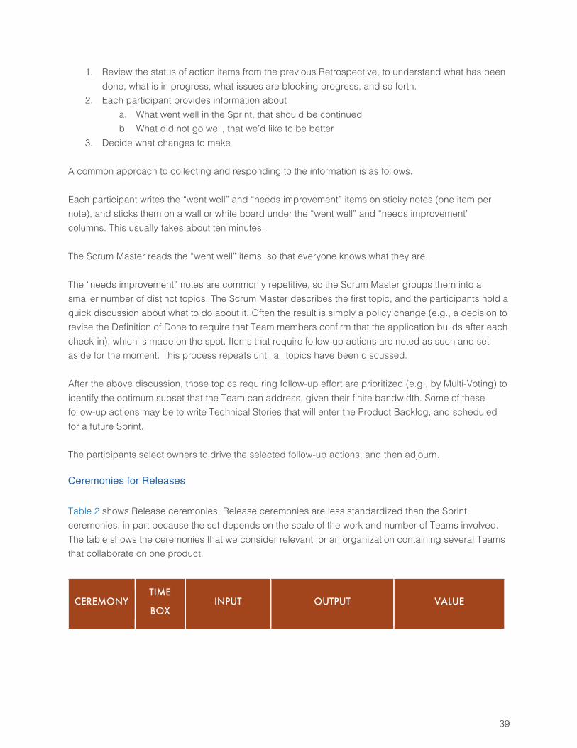
39
1. Review the status of action items from the previous Retrospective, to understand what has been done, what is in progress, what issues are blocking progress, and so forth.
2. Each participant provides information about a. What went well in the Sprint, that should be continued b. What did not go well, that we’d like to be better
3. Decide what changes to make A common approach to collecting and responding to the information is as follows. Each participant writes the “went well” and “needs improvement” items on sticky notes (one item per note), and sticks them on a wall or white board under the “went well” and “needs improvement” columns. This usually takes about ten minutes. The Scrum Master reads the “went well” items, so that everyone knows what they are. The “needs improvement” notes are commonly repetitive, so the Scrum Master groups them into a smaller number of distinct topics. The Scrum Master describes the first topic, and the participants hold a quick discussion about what to do about it. Often the result is simply a policy change (e.g., a decision to revise the Definition of Done to require that Team members confirm that the application builds after each check-in), which is made on the spot. Items that require follow-up actions are noted as such and set aside for the moment. This process repeats until all topics have been discussed. After the above discussion, those topics requiring follow-up effort are prioritized (e.g., by Multi-Voting) to identify the optimum subset that the Team can address, given their finite bandwidth. Some of these follow-up actions may be to write Technical Stories that will enter the Product Backlog, and scheduled for a future Sprint. The participants select owners to drive the selected follow-up actions, and then adjourn.
Ceremonies for Releases Table 2 shows Release ceremonies. Release ceremonies are less standardized than the Sprint ceremonies, in part because the set depends on the scale of the work and number of Teams involved. The table shows the ceremonies that we consider relevant for an organization containing several Teams that collaborate on one product.
CEREMONY TIME
BOX INPUT OUTPUT VALUE
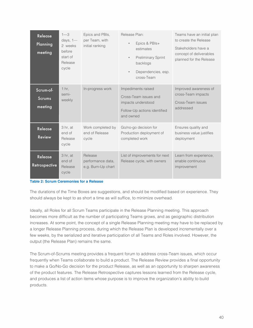
40
Release
Planning
meeting
1—3 days, 1—2 weeks before start of Release cycle
Epics and PBIs, per Team, with initial ranking
Release Plan:
• Epics & PBIs+ estimates
• Preliminary Sprint backlogs
• Dependencies, esp. cross-Team
Teams have an initial plan to create the Release
Stakeholders have a concept of deliverables planned for the Release
Scrum-of-
Scrums
meeting
1 hr, semi-weekly
In-progress work Impediments raised
Cross-Team issues and impacts understood
Follow-Up actions identified and owned
Improved awareness of cross-Team impacts
Cross-Team issues addressed
Release
Review
3 hr, at end of Release cycle
Work completed by end of Release cycle
Go/no-go decision for Production deployment of completed work
Ensures quality and business value justifies deployment
Release
Retrospective
3 hr, at end of Release cycle
Release performance data, e.g. Burn-Up chart
List of improvements for next Release cycle, with owners
Learn from experience, enable continuous improvement
Table 2: Scrum Ceremonies for a Release
The durations of the Time Boxes are suggestions, and should be modified based on experience. They should always be kept to as short a time as will suffice, to minimize overhead. Ideally, all Roles for all Scrum Teams participate in the Release Planning meeting. This approach becomes more difficult as the number of participating Teams grows, and as geographic distribution increases. At some point, the concept of a single Release Planning meeting may have to be replaced by a longer Release Planning process, during which the Release Plan is developed incrementally over a few weeks, by the serialized and iterative participation of all Teams and Roles involved. However, the output (the Release Plan) remains the same. The Scrum-of-Scrums meeting provides a frequent forum to address cross-Team issues, which occur frequently when Teams collaborate to build a product. The Release Review provides a final opportunity to make a Go/No-Go decision for the product Release, as well as an opportunity to sharpen awareness of the product features. The Release Retrospective captures lessons learned from the Release cycle, and produces a list of action items whose purpose is to improve the organization’s ability to build products.
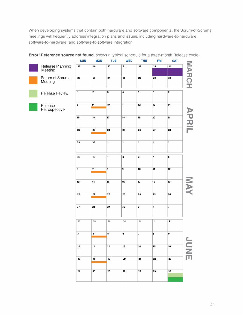
41
When developing systems that contain both hardware and software components, the Scrum-of-Scrums meetings will frequently address integration plans and issues, including hardware-to-hardware, software-to-hardware, and software-to-software integration. Error! Reference source not found. shows a typical schedule for a three-month Release cycle.
42
Figure 11: Typical Release Schedule
Release Planning Release Planning must be completed prior to the start of the Release cycle, and is usually scheduled to be done from one to four weeks before the start of the Release cycle. The purpose of Release Planning is to produce a Release Plan, which is an initial map of Epics and PBIs to Teams and Sprints in the Release cycle. As always in Scrum, the sequencing of work is driven by value, but constrained by dependencies, and must fit into the estimated Velocity for the Release. The Velocity information comes from the Scrum Masters, who estimate their Teams’ Velocity over the course of the planned Release cycle, based on forecasts of Team size and availability. Release Planning can be done in one large meeting, over one or two days, or incrementally, over a few weeks. Both approaches are considered here.
Single Release Planning Meeting The Program Manager facilitates this meeting, while the Area Product Owner provides overall guidance about requirements and business needs. The Release-Planning meeting can be quite large, as all members of all collaborating Scrum Teams attend, along with the Area Product Owner, Program Manager, and a scattering of other participants and stakeholders (e.g., executives, User Experience, Architecture, IT, Dev Ops, Marketing, etc.). Mixed hardware/software products may also involve people representing specialties such as electronics, mechanics, manufacturing, regulatory compliance, and so forth. Consequently, Release Planning can be a costly process, as we may need one or two full days of time from all of these people. The value of the Release Plan must justify the cost of Release Planning, or it is not worth doing. Common drivers for Release Planning include
1. Reduction in confusion due to planning cross-Team dependencies 2. The need to understand how external resources may be engaged 3. The need to plan for customer commitments
Following any introductory presentations desired, the participants meet in one large room, with one Team per table. Each Team works through a stack of requirements provided by their Team Product Owner. Each Team estimates any requirements not previously estimated, identifies and fills gaps, identifies cross-Team dependencies, and drafts its part of the Release Plan. Teams notify each other of cross-Team dependencies and negotiate how and when to schedule the associated work. They iterate through drafts of the Release Plan until they believe the plan is viable. (Teams may also spend much of their time in separate rooms for much of this work, and periodically return to the shared room to update the Release Planning Board.)

43
It is common for a Team to have to estimate a few hundred specifications (PBIs and Epics) in Release Planning meetings. The volume of estimates required precludes careful analysis of each item, so Teams often use the Affinity Estimation technique (as discussed in Section 0) to work through these items in a couple of hours. After estimation has been completed, Teams create plans by taping each requirement to the wall, and allocate items to Sprints based on size and dependencies. One wall might display requirements in (say) three parallel, horizontal rows (at one per Team), with cross-Team dependencies marked by strips of tape, ribbon, or yarn from predecessor to successor (see Figure 12). Note that PBIs may not cross Sprint boundaries, while Epics (which are placeholders for sets of PBIs yet to be written) may cross Sprint boundaries.
Figure 12: A Release Plan, as it Appears in the Release Planning Meeting
The Program Manager is responsible for ensuring that this array of paper is ultimately captured in condensed form as the Release Plan. All five roles participate in the Release Planning meeting. The Teams do the bulk of the work, with Scrum Masters facilitating as needed, and Team Product Owners providing guidance regarding requirements. The Area Product Owner and Program Manager participate as needed. The Area Product Owner provides the big-picture guidance regarding requirements and business value, and is ultimately responsible for scope trade-off decisions. The Program Manager focuses on ensuring that cross-Team dependencies are identified, as they will be involved in ensuring those dependencies are handled effectively during execution.
44
Finally, all parties should be aware that the Release scope may change dramatically, if business drivers change. This is normal and expected, but means that success is determined not by implementing the
scope of the initial Release Plan, but in ensuring that scope is managed throughout the Release
cycle, so that the evolving Release Plan always remains achievable and delivers the best possible
value for the effort expended during the Release cycle.
Incremental Release Planning While the preceding section presents a common way to do Release Planning, alternatives are possible. The various Roles may collaborate, formally or informally, in a number of shorter meetings, to assemble a Release Plan in increments. This approach may be more practical for environments where logistical issues make the default approach impractical, such as geographic distribution of Team members. What matters is that the Release Plan be completed in time, and that the Teams involved have confidence that the plan is achievable. There are no hard-and-fast rules about how to do incremental Release Planning, but this section gives some generally-useful guidance. This approach is most commonly driven by the need to collaborate across distributed groups, and often makes extensive use of collaboration tools such as web meetings, video conferencing, wikis, and so forth.
Scope Development and Estimation Team Product Owners write Epics and PBIs to be used in planning a future Release, weeks to months prior to when the Release Plan must be complete. Team members then provide estimates for these items in Backlog Grooming or Sprint Planning meetings, in addition to estimates for PBIs to be addressed in the Sprint being planned.
Release Plan Development Team Product Owners and Scrum Masters collaborate informally to draft their Teams’ portions of the Release plan. They seek Teams’ guidance and feedback as required, either informally, or in Backlog Grooming meetings. As always in Scrum, the sequencing of work is driven by value, but constrained by dependencies, and must fit into the estimated Velocity for the Release. The group of Program Manager, Area Product Owner, Scrum Masters, and Team Product Owners hold a series of mini-Release Planning meetings, each of which produces a new draft of the Release Plan that takes into account issues and dependencies identified to date. In between these meetings, the Teams review the plans and provide feedback. This sequence completes when the participants agree that the Release Plan is reliable enough to meet their goals.
Units for Estimation in Release Planning Practitioners in the Scrum world often state that each Team should be allowed to select its own units and scale for estimating PBIs. This preference is harmless for Scrum Teams that work alone, but introduces difficulties when Teams must collaborate to develop and execute a Release Plan. Executives and other
45
stakeholders commonly want simple metrics for work completed or remaining in a Release, aggregated across Teams, but such aggregation is not possible if Teams estimate PBIs in different units. Consequently, we recommend standardization of units across Teams that must collaborate, such that a PBI of size “5” (for example) communicates a consistent concept of size to all Teams. This kind of standardization is provided automatically if Teams use absolute sizing. If Teams use relative sizing, standardization is more difficult, and requires developing a common reference scale for Story Points across the Teams.
How to Estimate PBIs and Epics for Release Planning: Affinity Estimation The most convenient method for estimating the PBIs and Epics that will comprise a Release is to estimate them incrementally, over time, prior to Release Planning. However, Release Planning often necessitates estimating the duration and effort of a large number of items in a short time, so we will address that need here. The Affinity Estimation technique is an effective way to estimate many items, quickly. The usual three Scrum Roles participate as follows. The Product Owner prepares by printing out the relevant PBIs and Epics on paper or sticky notes, and placing them on a table in the room where the estimation work will be done. In the first part of the meeting, Team members sort items in order of increasing size from left to right, by taping them to a wall (or laying them on a table, etc.). This work is done silently. Each Team member takes an item from the Backlog pile, and places it on the sorting wall in the place he or she thinks is appropriate. The Team member also reviews items that have been placed on the wall, and moves any that seem to be in the wrong place, to the right place. The Team member then picks a new item off the Backlog pile, and repeats. Eventually, the Backlog pile disappears, and Team members spend their time re-sorting items on the sorting wall. Any items that do not stabilize are removed for later consideration. The remaining items do settle down, and the Scrum Master makes a decision to halt the sorting exercise when activity has mostly ceased. In the second part of the meeting, Team members discuss where to draw lines denoting the size bins, commonly using the same (Fibonacci-based) scale adopted for the Planning Poker method (Section 0). After they draw these lines (with masking tape or other non-damaging means!), all items have estimates. The appearance of a completed exercise in Affinity Estimation is illustrated in Figure 13.
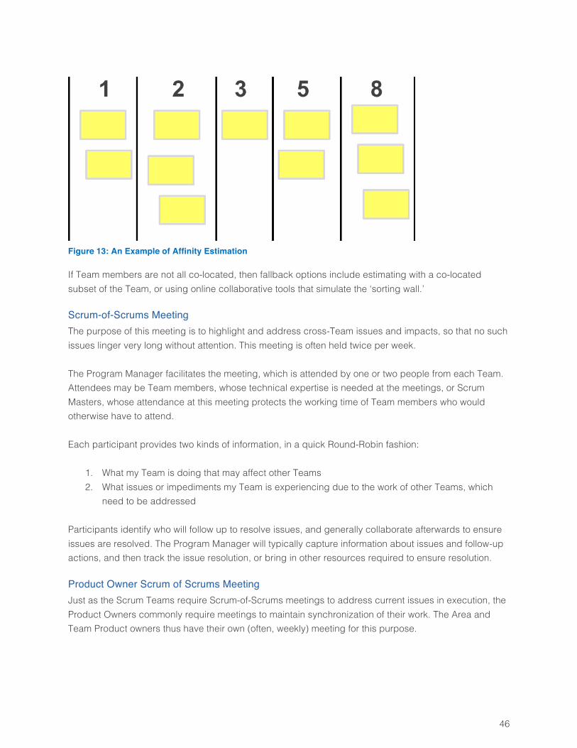
46
Figure 13: An Example of Affinity Estimation
If Team members are not all co-located, then fallback options include estimating with a co-located subset of the Team, or using online collaborative tools that simulate the ‘sorting wall.’
Scrum-of-Scrums Meeting The purpose of this meeting is to highlight and address cross-Team issues and impacts, so that no such issues linger very long without attention. This meeting is often held twice per week. The Program Manager facilitates the meeting, which is attended by one or two people from each Team. Attendees may be Team members, whose technical expertise is needed at the meetings, or Scrum Masters, whose attendance at this meeting protects the working time of Team members who would otherwise have to attend. Each participant provides two kinds of information, in a quick Round-Robin fashion:
1. What my Team is doing that may affect other Teams 2. What issues or impediments my Team is experiencing due to the work of other Teams, which
need to be addressed Participants identify who will follow up to resolve issues, and generally collaborate afterwards to ensure issues are resolved. The Program Manager will typically capture information about issues and follow-up actions, and then track the issue resolution, or bring in other resources required to ensure resolution.
Product Owner Scrum of Scrums Meeting Just as the Scrum Teams require Scrum-of-Scrums meetings to address current issues in execution, the Product Owners commonly require meetings to maintain synchronization of their work. The Area and Team Product owners thus have their own (often, weekly) meeting for this purpose.
47
The purpose of this meeting is for Area and Team Product Owners to report their personal work status to each other, and to assess progress towards the Release goals. The Area Product Owner facilitates the meeting. The Status-Report format is simple. Each participant summarizes, briefly,
1. What work I’ve done since our last meeting 2. What I’m planning to do before our next meeting 3. Issues that are interfering with my progress 4. How my work on product scope may affect others
Unless blocking issues have solutions that can be described very quickly (say, a minute), the standard response to issues is to identify who will meet to address them after this meeting. This approach keeps this meeting acceptably brief. Next, someone (who may be the Area Product Owner, though this is not required) shows the Burn-Up chart (Section 0), and describes how well or poorly progress agrees with the plan. If progress is not satisfactory (meaning the planned Release scope may not be accomplishable), the participants discuss how best to address the problem. In order of decreasing frequency, the most common responses include
• Reducing scope of specific features • Reducing scope by dropping specific features • Moving the Release date out • Deciding to request that more resources be provided to the product
If progress exceeds expectations, then the participants usually decide what to add to the scope, and modify plans accordingly.
Release Review This is a very simple meeting of the Area and Team Product Owners, at the end of the Release cycle, facilitated by the Area Product Owner. The purpose of the Release Review is to confirm that the Product quality and business value justify releasing the deliverables developed by the Project Teams in this Release cycle. The Area Product Owner has the authority to release, or not release, the product at this time. Failure to release at this point is a very rare occurrence, as the Product Owners have been monitoring progress throughout the entire Release cycle.
Release Retrospective The purpose of this meeting is to identify ways to improve the entire Release process. The Program Manager facilitates, and the Scrum Masters and Team Product Owners attend. Attendance by others (e.g., Area Product Owner) is optional and decided locally.
48
Scrum Masters should prepare by bringing findings from their Teams’ Sprint Retrospectives that are relevant for this meeting (i.e., which cannot be handled at the Team level). Aside from this bit of preparation, the format and conduct of this meeting is identical to that of a Team Sprint Retrospective meeting, and will not be repeated here. Note that recommendations from this meeting often require management or executive approval and action.
Tracking and Metrics The following sections present standard approaches to tracking progress for Sprint or Release cycles. The key tracking tools for a Scrum Sprint are the Taskboard and Burndown chart, while Burn-Up charts are useful for Releases.
Tracking Progress for a Sprint Figure 14 shows a typical Taskboard and Burndown chart, and shows the current status in the middle of a Sprint. The Taskboard shows the Tasks associated with different PBIs, and the state of each Task. The PBIs are listed in rank order from top to bottom. The Burndown chart shows the hours remaining across all Tasks planned for the Sprint but not yet completed, along with a diagonal line that shows the planned values. The diagonal plan line is a straight line that connects the known initial state with the planned final state. Work is ahead of schedule if the bars for the daily values are below the plan line, and behind if they are above the line. The initial state for the Burndown chart is the total effort planned for the Sprint, computed as the sum of the hour estimates for all Tasks associated with all PBIs planned for the Sprint. This initial state occurs on “Day 0” of the Sprint on the chart (i.e., before the start of work on Day 1 of the Sprint). The planned final state is defined by zero hours of work remaining at the end of the last working day of the Sprint (e.g., Day 10 for a two-week Sprint). Only weekdays are plotted (not weekends). Each day’s value is given by the sum of Task estimates for Tasks that have not been completed by the end of that day. The Taskboard and Burndown chart enable a clear understanding of how well the work of the Sprint is going. The Burndown chart shows aggregate progress, and reveals whether work is being accomplished at the intended rate. The Taskboard shows complete information about the current state of work. Together, they provide great insight into how well the Sprint is progressing.
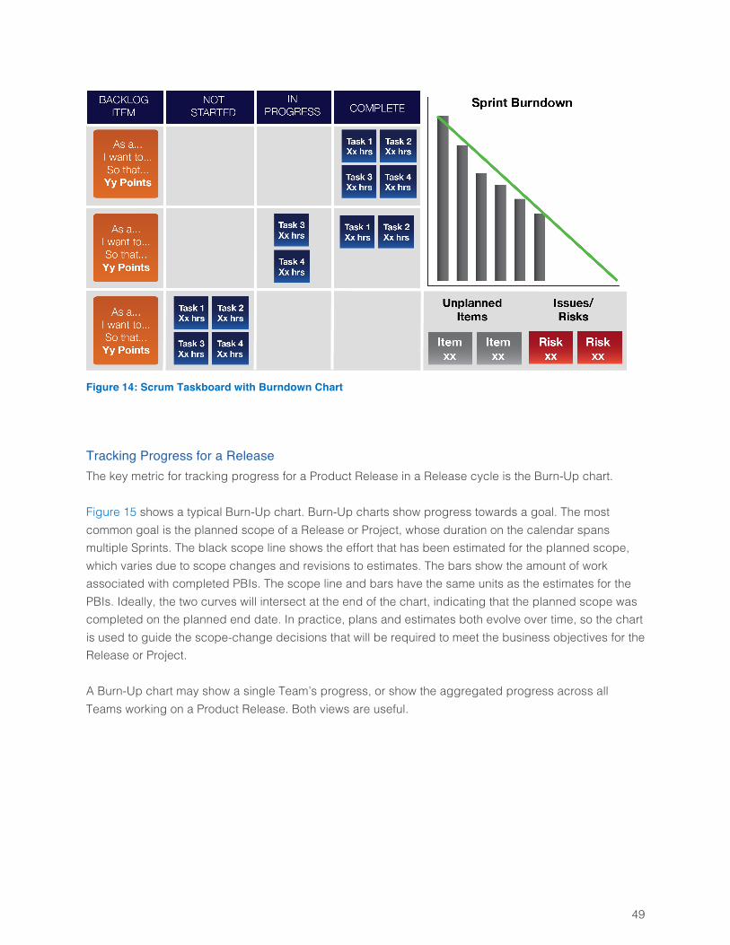
49
Figure 14: Scrum Taskboard with Burndown Chart
Tracking Progress for a Release The key metric for tracking progress for a Product Release in a Release cycle is the Burn-Up chart. Figure 15 shows a typical Burn-Up chart. Burn-Up charts show progress towards a goal. The most common goal is the planned scope of a Release or Project, whose duration on the calendar spans multiple Sprints. The black scope line shows the effort that has been estimated for the planned scope, which varies due to scope changes and revisions to estimates. The bars show the amount of work associated with completed PBIs. The scope line and bars have the same units as the estimates for the PBIs. Ideally, the two curves will intersect at the end of the chart, indicating that the planned scope was completed on the planned end date. In practice, plans and estimates both evolve over time, so the chart is used to guide the scope-change decisions that will be required to meet the business objectives for the Release or Project. A Burn-Up chart may show a single Team’s progress, or show the aggregated progress across all Teams working on a Product Release. Both views are useful.
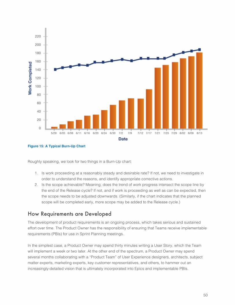
50
Figure 15: A Typical Burn-Up Chart
Roughly speaking, we look for two things in a Burn-Up chart:
1. Is work proceeding at a reasonably steady and desirable rate? If not, we need to investigate in order to understand the reasons, and identify appropriate corrective actions.
2. Is the scope achievable? Meaning, does the trend of work progress intersect the scope line by the end of the Release cycle? If not, and if work is proceeding as well as can be expected, then the scope needs to be adjusted downwards. (Similarly, if the chart indicates that the planned scope will be completed early, more scope may be added to the Release cycle.)
How Requirements are Developed The development of product requirements is an ongoing process, which takes serious and sustained effort over time. The Product Owner has the responsibility of ensuring that Teams receive implementable requirements (PBIs) for use in Sprint Planning meetings. In the simplest case, a Product Owner may spend thirty minutes writing a User Story, which the Team will implement a week or two later. At the other end of the spectrum, a Product Owner may spend several months collaborating with a “Product Team” of User Experience designers, architects, subject matter experts, marketing experts, key customer representatives, and others, to hammer out an increasingly-detailed vision that is ultimately incorporated into Epics and implementable PBIs.

51
Thus the day-to-day experience of a Product Owner can range from “one-man band” to conductor of an orchestra, depending on how many people’s efforts must be guided and synchronized to produce the implementable requirements that a Team must have. In all cases, the Product Owner makes the decisions about what to build based on business value, feasibility, and cost, and is the funnel through which all requests for a Team’s work must go (including requests that come from the Team). Detailed guidance about the mechanics of requirements development is beyond the scope of this document. However, we do present some simple guidelines.
• A PBI cannot enter a Sprint Planning meeting unless it contains the information required for Teams to implement its deliverables. It is acceptable and expected for the Team to have a number of questions for the Product Owner, about various details, throughout the Sprint. It is not acceptable for the Team to be stalled for days, routinely, while others have debates about what the PBI should contain. Therefore the Product Owner must consult with subject-matter experts, and “do his homework” on the risks and feasibility of implementing a PBI, before that PBI can enter a Sprint Planning meeting.
• User Experience (UX) and architectural guidance needed for a PBI’s implementation must be made available, and incorporated as appropriate into the PBI itself, before the PBI can be considered ready for implementation. This guidance may take the form of wireframe or high-fidelity screen mockups, design patterns, or anything else that is required, and may be attached to the PBI, or referenced in the PBI’s text by a link to a separate artifact.
• It is unwise to create large, detailed UX or architecture designs in one big effort, and then hand the whole batch off to a Team at once. It is better to develop rough conceptions of long-term needs and solutions, but design and build the detailed pieces on a “Just in Time” basis. The former slows value delivery, and commonly wastes effort on developing artifacts and plans that will turn out to be wrong or useless.
Practical Example of an Agile Hardware Project In this section, we will follow the evolution of a hardware product’s development, using the Agile process we have defined. The product is a cardiac monitor, produced by a fictitious company named TelCorp. TelCorp’s mission statement provides a succinct description of what the company does:
TelCorp develops, sells, supports, and provides training for medical devices that support surgical
procedures and patient monitoring in hospitals. TelCorp is dedicated to enabling the best
possible medical care for patients, by producing networked medical devices whose integrated
management provides benefits that far exceed the sum of the individual products.
52
The Project and Product Definition The project is to design and develop a cardiac monitor for patient monitoring in hospital environments. The product is a clean-sheet design for TelCorp, and incorporates new features that provides a higher level of hospital data integration and better interoperability with our overall product line. Part of the motivation for the new design is the advancement in micro-controllers and converters, which enable a new and more capable platform. Also new in the product is its interaction with cloud storage, so that all data is stored both locally and in the cloud, while ensuring HIPPA compliance. Finally, this product is aligned with the overall portfolio plan, and its projected selling price of $39K is targeted towards the highest volume of hospital patient monitors. The program priorities are:
1. Time to market 2. Accuracy of heart rate monitoring 2x over leading competitor 3. Implementing all Series III API requirements for TelCorp interoperability 4. Product Cost 5. Project Cost
The project is organized as a set of self-organized Team, each having the mix of skills required to implement and validate the PBIs they are expected to complete. The Teams are matrix organizations, with member of one Team reporting to more than one functional manager.
The Team Definitions Proper Team definition is critical to success. Each Team owns a particular category of deliverables, and work on the product as a whole is allocated to Teams based on their focus. Each Team must contain all of the skill sets needed to produce tested and working deliverables. The development of the cardiac monitor is divided across four Scrum Teams. The overall product definition comes from Daniel, who is designated as the Area Product Owner. Ulrich, the Program Manager, is responsible for facilitating Release Planning, and managing cross-Team dependencies. The two Scrum Masters (Caroline and Fred) fill their roles for two Teams each. Each Team also has a single Team Product Owner, who is responsible for ensuring that Team’s requirements (Stories) are properly defined and sequenced. The wide variation in Teams’ areas of focus means that it is impractical to have one person be the Team Product Owner for more than one Team. At the same time, the role of Team Product Owner for a single Team does not entail enough work to keep one person occupied full time. Thus the compromise here is to designate each Team’s lead engineer to serve as part-time Product Owner for that Team.
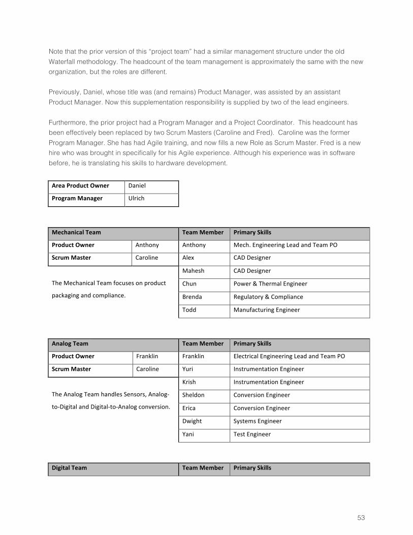
53
Note that the prior version of this “project team” had a similar management structure under the old Waterfall methodology. The headcount of the team management is approximately the same with the new organization, but the roles are different. Previously, Daniel, whose title was (and remains) Product Manager, was assisted by an assistant Product Manager. Now this supplementation responsibility is supplied by two of the lead engineers. Furthermore, the prior project had a Program Manager and a Project Coordinator. This headcount has been effectively been replaced by two Scrum Masters (Caroline and Fred). Caroline was the former Program Manager. She has had Agile training, and now fills a new Role as Scrum Master. Fred is a new hire who was brought in specifically for his Agile experience. Although his experience was in software before, he is translating his skills to hardware development.
AreaProductOwner Daniel
ProgramManager Ulrich
MechanicalTeam TeamMember PrimarySkills
ProductOwner Anthony Anthony Mech.EngineeringLeadandTeamPO
ScrumMaster Caroline Alex CADDesigner
TheMechanicalTeamfocusesonproduct
packagingandcompliance.
Mahesh CADDesigner
Chun Power&ThermalEngineer
Brenda Regulatory&Compliance
Todd ManufacturingEngineer
AnalogTeam TeamMember PrimarySkills
ProductOwner Franklin Franklin ElectricalEngineeringLeadandTeamPO
ScrumMaster Caroline Yuri InstrumentationEngineer
TheAnalogTeamhandlesSensors,Analog-
to-DigitalandDigital-to-Analogconversion.
Krish InstrumentationEngineer
Sheldon ConversionEngineer
Erica ConversionEngineer
Dwight SystemsEngineer
Yani TestEngineer
DigitalTeam TeamMember PrimarySkills
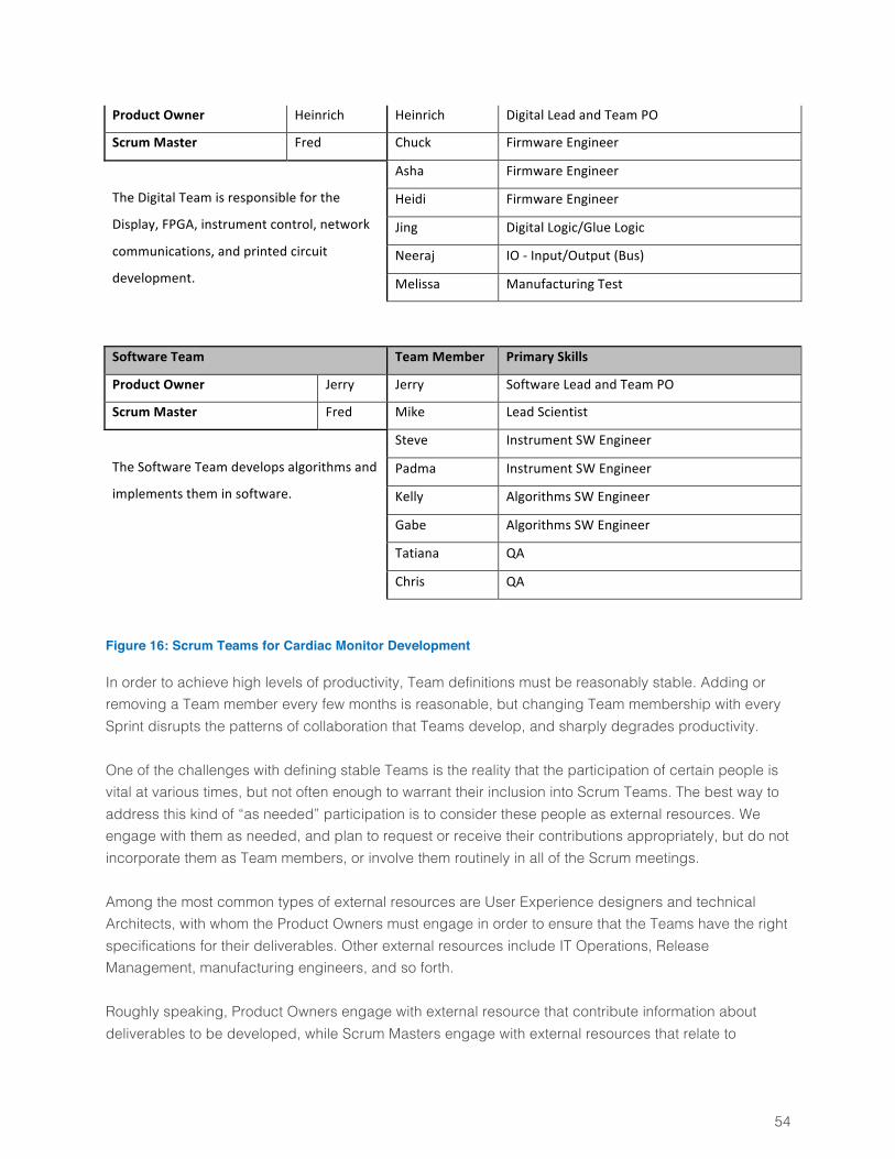
54
ProductOwner Heinrich Heinrich DigitalLeadandTeamPO
ScrumMaster Fred Chuck FirmwareEngineer
TheDigitalTeamisresponsibleforthe
Display,FPGA,instrumentcontrol,network
communications,andprintedcircuit
development.
Asha FirmwareEngineer
Heidi FirmwareEngineer
Jing DigitalLogic/GlueLogic
Neeraj IO-Input/Output(Bus)
Melissa ManufacturingTest
SoftwareTeam TeamMember PrimarySkills
ProductOwner Jerry Jerry SoftwareLeadandTeamPO
ScrumMaster Fred Mike LeadScientist
TheSoftwareTeamdevelopsalgorithmsand
implementstheminsoftware.
Steve InstrumentSWEngineer
Padma InstrumentSWEngineer
Kelly AlgorithmsSWEngineer
Gabe AlgorithmsSWEngineer
Tatiana QA
Chris QA
Figure 16: Scrum Teams for Cardiac Monitor Development
In order to achieve high levels of productivity, Team definitions must be reasonably stable. Adding or removing a Team member every few months is reasonable, but changing Team membership with every Sprint disrupts the patterns of collaboration that Teams develop, and sharply degrades productivity. One of the challenges with defining stable Teams is the reality that the participation of certain people is vital at various times, but not often enough to warrant their inclusion into Scrum Teams. The best way to address this kind of “as needed” participation is to consider these people as external resources. We engage with them as needed, and plan to request or receive their contributions appropriately, but do not incorporate them as Team members, or involve them routinely in all of the Scrum meetings. Among the most common types of external resources are User Experience designers and technical Architects, with whom the Product Owners must engage in order to ensure that the Teams have the right specifications for their deliverables. Other external resources include IT Operations, Release Management, manufacturing engineers, and so forth. Roughly speaking, Product Owners engage with external resource that contribute information about deliverables to be developed, while Scrum Masters engage with external resources that relate to
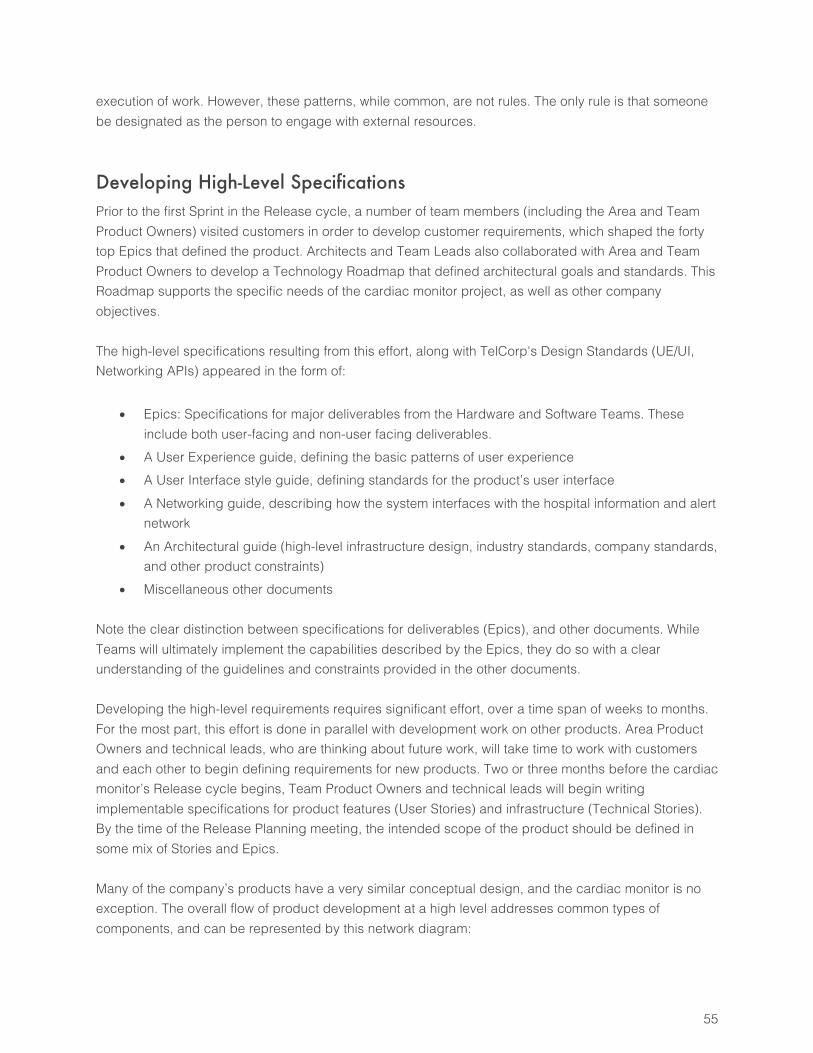
55
execution of work. However, these patterns, while common, are not rules. The only rule is that someone be designated as the person to engage with external resources.
Developing High-Level Specifications Prior to the first Sprint in the Release cycle, a number of team members (including the Area and Team Product Owners) visited customers in order to develop customer requirements, which shaped the forty top Epics that defined the product. Architects and Team Leads also collaborated with Area and Team Product Owners to develop a Technology Roadmap that defined architectural goals and standards. This Roadmap supports the specific needs of the cardiac monitor project, as well as other company objectives. The high-level specifications resulting from this effort, along with TelCorp's Design Standards (UE/UI, Networking APIs) appeared in the form of:
• Epics: Specifications for major deliverables from the Hardware and Software Teams. These include both user-facing and non-user facing deliverables.
• A User Experience guide, defining the basic patterns of user experience • A User Interface style guide, defining standards for the product’s user interface • A Networking guide, describing how the system interfaces with the hospital information and alert
network • An Architectural guide (high-level infrastructure design, industry standards, company standards,
and other product constraints) • Miscellaneous other documents
Note the clear distinction between specifications for deliverables (Epics), and other documents. While Teams will ultimately implement the capabilities described by the Epics, they do so with a clear understanding of the guidelines and constraints provided in the other documents. Developing the high-level requirements requires significant effort, over a time span of weeks to months. For the most part, this effort is done in parallel with development work on other products. Area Product Owners and technical leads, who are thinking about future work, will take time to work with customers and each other to begin defining requirements for new products. Two or three months before the cardiac monitor’s Release cycle begins, Team Product Owners and technical leads will begin writing implementable specifications for product features (User Stories) and infrastructure (Technical Stories). By the time of the Release Planning meeting, the intended scope of the product should be defined in some mix of Stories and Epics. Many of the company’s products have a very similar conceptual design, and the cardiac monitor is no exception. The overall flow of product development at a high level addresses common types of components, and can be represented by this network diagram:
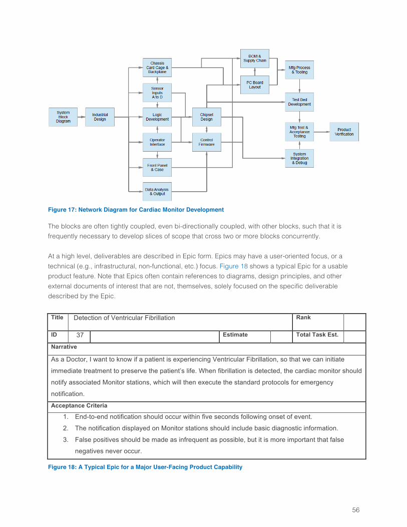
56
Figure 17: Network Diagram for Cardiac Monitor Development
The blocks are often tightly coupled, even bi-directionally coupled, with other blocks, such that it is frequently necessary to develop slices of scope that cross two or more blocks concurrently. At a high level, deliverables are described in Epic form. Epics may have a user-oriented focus, or a technical (e.g., infrastructural, non-functional, etc.) focus. Figure 18 shows a typical Epic for a usable product feature. Note that Epics often contain references to diagrams, design principles, and other external documents of interest that are not, themselves, solely focused on the specific deliverable described by the Epic. Title Detection of Ventricular Fibrillation Rank
ID 37 Estimate Total Task Est.
Narrative
As a Doctor, I want to know if a patient is experiencing Ventricular Fibrillation, so that we can initiate
immediate treatment to preserve the patient’s life. When fibrillation is detected, the cardiac monitor should
notify associated Monitor stations, which will then execute the standard protocols for emergency
notification.
Acceptance Criteria
1. End-to-end notification should occur within five seconds following onset of event.
2. The notification displayed on Monitor stations should include basic diagnostic information.
3. False positives should be made as infrequent as possible, but it is more important that false
negatives never occur.
Figure 18: A Typical Epic for a Major User-Facing Product Capability
57
Over the course of the Release cycle, the Team Product Owners and Team members will create a decomposition of this Epic (and others) into User and Technical Stories to be implemented in various Sprints. The high-level Epics are commonly defined through a collaborative effort involving the Area and Team Product Owners, with the bulk of the actual writing falling to the Team Product Owners.
Developing Detailed Specifications Team Product Owners cannot generally write requirements with sufficient clarity and focus to meet all of the Teams’ needs. Nor can they usually write the specifications for the all of the non-user-facing deliverables which are always present, and often highly technical in nature. For these reasons, Product Owners must collaborate closely with their Teams to develop the fine-grained and implementable specifications required by those Teams. As described in Section 0, Epics must be decomposed into User Stories (for user-facing product behaviors), and Technical Stories (for other deliverables). These Stories are the specifications for actual Team deliverables, and must be clearly written, properly ranked (sequenced), and well-understood by the Teams before the Stories can enter a Sprint Planning meeting. Much of the work of developing suitable Stories occurs within or following the Backlog Grooming meetings of Section 0. In the four weeks prior to the Release Planning meeting for the cardiac monitor work, the Team Product Owners meet twice weekly with their Teams (and Scrum Masters) in Backlog Grooming meetings.13 The Product Owners bring draft Epics and Stories that Team members have previously read, and collect feedback. The Team members provide the feedback needed to improve Stories and decompose Epics. The Team members also discover needs for technical work, and develop Technical Stories after the meeting, for review in the next meeting. The continuing series of Backlog Grooming meetings enables the steady flow of fine-grained specifications the Teams require for their Sprint Planning meetings. Backlog Grooming meetings do more than turn ideas into Stories. They also provide a standard forum for collaboration and discovery that frequently yields improved ideas about what to develop, even to the point of generating improved product directions that differ substantially from previous plans. The Area Product Owner, Daniel, is the authority on what the full set of Scrum Teams will develop. He is empowered to make major changes in scope and direction before and during development of the product. He does not have to seek approval for changes unless it is clear that they will impact other initiatives the company is pursuing, will require significantly greater investment than was originally planned, or may jeopardize the business objectives of this product. He does not make these changes in a vacuum—it is his responsibility to collaborate with other products and business stakeholders to ensure that the product’s evolving definition is appropriate and dependent plans are suitably revised—but he does have the authority to make such changes.
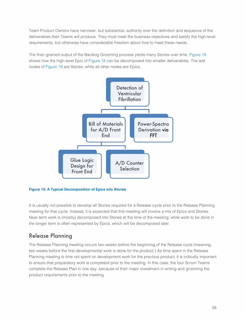
58
Team Product Owners have narrower, but substantial, authority over the definition and sequence of the deliverables their Teams will produce. They must meet the business objectives and satisfy the high-level requirements, but otherwise have considerable freedom about how to meet these needs. The finer-grained output of the Backlog Grooming process yields many Stories over time. Figure 19 shows how the high-level Epic of Figure 18 can be decomposed into smaller deliverables. The leaf nodes of Figure 19 are Stories, while all other nodes are Epics.
Figure 19: A Typical Decomposition of Epics into Stories
It is usually not possible to develop all Stories required for a Release cycle prior to the Release Planning meeting for that cycle. Instead, it is expected that this meeting will involve a mix of Epics and Stories. Near-term work is (mostly) decomposed into Stories at the time of the meeting; while work to be done in the longer term is often represented by Epics, which will be decomposed later.
Release Planning The Release Planning meeting occurs two weeks before the beginning of the Release cycle (meaning, two weeks before the first developmental work is done for the product.) As time spent in the Release Planning meeting is time not spent on development work for the previous product, it is critically important to ensure that preparatory work is completed prior to the meeting. In this case, the four Scrum Teams complete the Release Plan in one day, because of their major investment in writing and grooming the product requirements prior to the meeting.
Detection of Ventricular Fibrillation
Bill of Materials for A/D Front
End
Glue Logic Design for Front End
A/D Counter Selection
Power-Spectra Derivation via
FFT
59
Developing the Release Plan The Teams follow the planning process described in Section 0. Team Product owners bring printed copies of all of the Epics and Stories developed for this product, for both Teams, along with any other documents that may be useful for planning purposes. The Program Manager, Ulrich, facilitates the planning session. The Scrum Masters guide their Teams to do their parts, while Team Product Owners develop or modify Stories and Epics as needed in the meeting. The Area Product Owner, Daniel, assists with insight about what the specifications mean. Crucially, Daniel also makes scope trade-off decisions required in order to meet the desired timeline, based on business objectives. The Release Plan developed in this meeting has the general form of Figure 12, but contains much more detail (e.g., hundreds of Epics and Stories, and associated dependencies). On conclusion of the meeting, all four Teams have agreed that the Release Plan is achievable. All Teams are even more confident that this is the best Release Plan they can create at this time. Finally, and perhaps most importantly, everyone involved in this planning exercise knows that the reality will diverge from the plan. The Teams will not succeed because they have created a reliable plan. They will succeed in large part because Daniel and the Team Product Owners will control and revise the scope throughout the Release cycle, to ensure that the Teams deliver the maximum value possible in that period of time.
The Structure of the Release The structure of the Release cycle is driven primarily by the constraints of hardware development, as the focus of the Hardware Team’s work changes over the course of the Release cycle. The network diagram of Figure 17 provides some initial insight into the natural flow of work, which is elaborated and refined in Release Planning. A high-level summary of the Release Plan, shown in Figure 20, shows how the focus of work evolves over the span of the Release cycle. Figure 20 illustrates some common patterns. The hardware and software development proceed in parallel. The Software Team uses two-week Sprints, while the Hardware Teams uses four-week. The longer Sprints are necessary for the slower-moving hardware development process, as the minimum reasonable size (in terms of work) of the hardware deliverables is substantially larger than that of software deliverables. The Sprint boundaries for all Teams align every four weeks, to make planning and collaboration easier. Teams integrate and conduct integration testing at every practical opportunity throughout the Release cycle, deferring to later times only the integration work that physically cannot be done earlier. The Software Team does pure software development, and relies heavily on emulation of hardware (early in the Release cycle) and prototypes (later in the Release cycle). The Hardware Team designs and builds (or has built for them) prototypes of the hardware, along with emulations to support the early software work. The Analog and Digital Hardware Teams commonly do
60
some software and firmware development as well, creating basic low-level drivers, other internal capabilities, and programmatic interfaces used by the Software Team. The growing use of full-scale hardware prototypes over time causes significant increases in development cost over time, in contrast to the relatively flat software-development costs. The type of work that the Software Team does changes little over time. The specific deliverables change, but the daily experience of development work is mostly similar from Sprint to Sprint. This similarity does not apply to the Hardware Team, whose deliverables are qualitatively different in later Sprints of the Release cycle, compared to earlier Sprints. Software design work is normally done on an incremental and Just-in-Time (JIT) basis, throughout the Release cycle, as needed. Hardware design is more front-loaded in the Release cycle, because the cost of change of hardware is so much higher than for software that it is important to minimize design changes (analogous to “refactoring” in the software world), and because the constraints of hardware development narrow the decision space enough to provide more design reliability than is commonly the case for software design work. The focus and associated headcount of the hardware work evolves as shown in the diagram. The Architecture and User-Interface design work is substantial at the start, and then tails off. The test and validation work for the working hardware components is small at first, and increases over time. Finally, there will be a Hardening Sprint at the end of the Release cycle. Integration testing is done as early and often as possible throughout the Release cycle, but there is always a certain amount of integration, testing, and other work that cannot be done while the product is under development. The latter type of work is done in Hardening Sprints, after product development has completed. It is important to understand that the only work done in Hardening Sprints is work that cannot be done earlier, and hardening Sprints should never be used as a place to dump work that people would rather postpone.
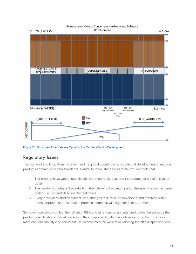
61
HWSW
S0– HW(4WEEKS) S11- HW
ARCHITECTURE&REQUIREMENTS INTEGRATION
S0– SW(2WEEKS) S22- SW
TIME
UI/ARCHITECTURE TEST/VALIDATION
ReleaseLevelViewofConcurrentHardwareandSoftwareDevelopment
S06– HWEng.Prototype
S07– HOPilot
S08– HWPre-Production
DEPENDENCIES
HEAD
COUN
T
Figure 20: Structure of the Release Cycle for the Cardiac-Monitor Development
Regulatory Issues The US Food and Drug Administration, and its global counterparts, require that development of medical products adheres to certain standards. Central to these standards are the requirements that:
1. The product have written specifications that correctly describe the product, at a useful level of detail
2. The vendor provides a “traceability matrix” showing how each part of the specification has been tested (i.e., list and describe the test cases)
3. Every product-related document, and changes to it, must be developed and archived with a formal approval and distribution process, complete with signoffs from approvers
Some vendors simply collect the full set of PBIs and other design artifacts, and define the set to be the product specifications. Daniel prefers a different approach, which entails more work, but provides a more conventional style of document. He incorporates the work of developing the official specifications,
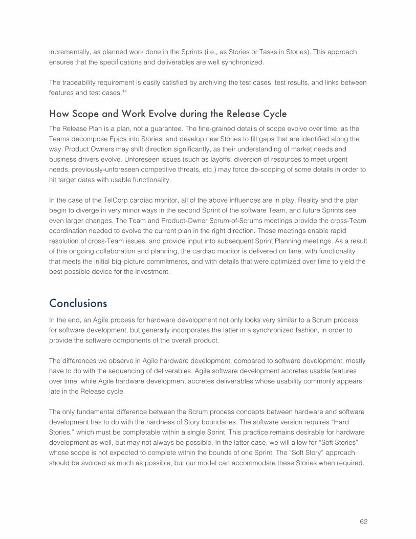
62
incrementally, as planned work done in the Sprints (i.e., as Stories or Tasks in Stories). This approach ensures that the specifications and deliverables are well synchronized. The traceability requirement is easily satisfied by archiving the test cases, test results, and links between features and test cases.14
How Scope and Work Evolve during the Release Cycle The Release Plan is a plan, not a guarantee. The fine-grained details of scope evolve over time, as the Teams decompose Epics into Stories, and develop new Stories to fill gaps that are identified along the way. Product Owners may shift direction significantly, as their understanding of market needs and business drivers evolve. Unforeseen issues (such as layoffs, diversion of resources to meet urgent needs, previously-unforeseen competitive threats, etc.) may force de-scoping of some details in order to hit target dates with usable functionality. In the case of the TelCorp cardiac monitor, all of the above influences are in play. Reality and the plan begin to diverge in very minor ways in the second Sprint of the software Team, and future Sprints see even larger changes. The Team and Product-Owner Scrum-of-Scrums meetings provide the cross-Team coordination needed to evolve the current plan in the right direction. These meetings enable rapid resolution of cross-Team issues, and provide input into subsequent Sprint Planning meetings. As a result of this ongoing collaboration and planning, the cardiac monitor is delivered on time, with functionality that meets the initial big-picture commitments, and with details that were optimized over time to yield the best possible device for the investment.
Conclusions In the end, an Agile process for hardware development not only looks very similar to a Scrum process for software development, but generally incorporates the latter in a synchronized fashion, in order to provide the software components of the overall product. The differences we observe in Agile hardware development, compared to software development, mostly have to do with the sequencing of deliverables. Agile software development accretes usable features over time, while Agile hardware development accretes deliverables whose usability commonly appears late in the Release cycle. The only fundamental difference between the Scrum process concepts between hardware and software development has to do with the hardness of Story boundaries. The software version requires “Hard Stories,” which must be completable within a single Sprint. This practice remains desirable for hardware development as well, but may not always be possible. In the latter case, we will allow for “Soft Stories” whose scope is not expected to complete within the bounds of one Sprint. The “Soft Story” approach should be avoided as much as possible, but our model can accommodate these Stories when required.
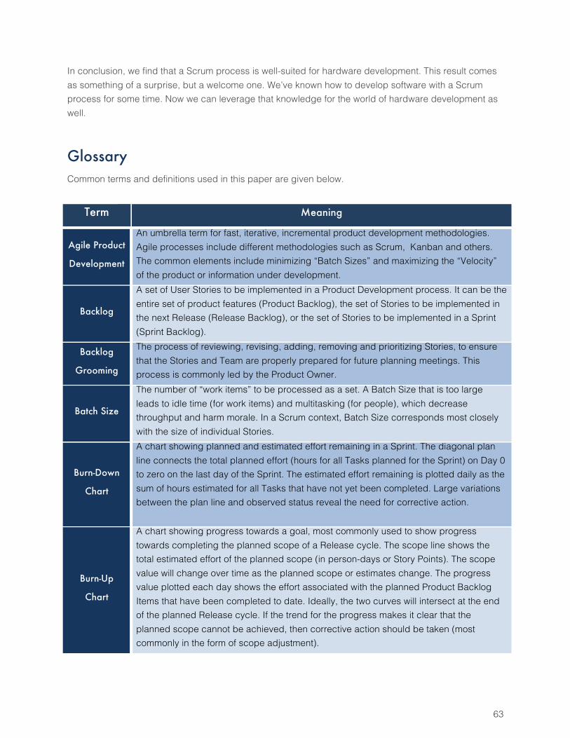
63
In conclusion, we find that a Scrum process is well-suited for hardware development. This result comes as something of a surprise, but a welcome one. We’ve known how to develop software with a Scrum process for some time. Now we can leverage that knowledge for the world of hardware development as well.
Glossary Common terms and definitions used in this paper are given below.
Term Meaning
Agile Product
Development
An umbrella term for fast, iterative, incremental product development methodologies. Agile processes include different methodologies such as Scrum, Kanban and others. The common elements include minimizing “Batch Sizes” and maximizing the “Velocity” of the product or information under development.
Backlog
A set of User Stories to be implemented in a Product Development process. It can be the entire set of product features (Product Backlog), the set of Stories to be implemented in the next Release (Release Backlog), or the set of Stories to be implemented in a Sprint (Sprint Backlog).
Backlog
Grooming
The process of reviewing, revising, adding, removing and prioritizing Stories, to ensure that the Stories and Team are properly prepared for future planning meetings. This process is commonly led by the Product Owner.
Batch Size
The number of “work items” to be processed as a set. A Batch Size that is too large leads to idle time (for work items) and multitasking (for people), which decrease throughput and harm morale. In a Scrum context, Batch Size corresponds most closely with the size of individual Stories.
Burn-Down
Chart
A chart showing planned and estimated effort remaining in a Sprint. The diagonal plan line connects the total planned effort (hours for all Tasks planned for the Sprint) on Day 0 to zero on the last day of the Sprint. The estimated effort remaining is plotted daily as the sum of hours estimated for all Tasks that have not yet been completed. Large variations between the plan line and observed status reveal the need for corrective action.
Burn-Up
Chart
A chart showing progress towards a goal, most commonly used to show progress towards completing the planned scope of a Release cycle. The scope line shows the total estimated effort of the planned scope (in person-days or Story Points). The scope value will change over time as the planned scope or estimates change. The progress value plotted each day shows the effort associated with the planned Product Backlog Items that have been completed to date. Ideally, the two curves will intersect at the end of the planned Release cycle. If the trend for the progress makes it clear that the planned scope cannot be achieved, then corrective action should be taken (most commonly in the form of scope adjustment).
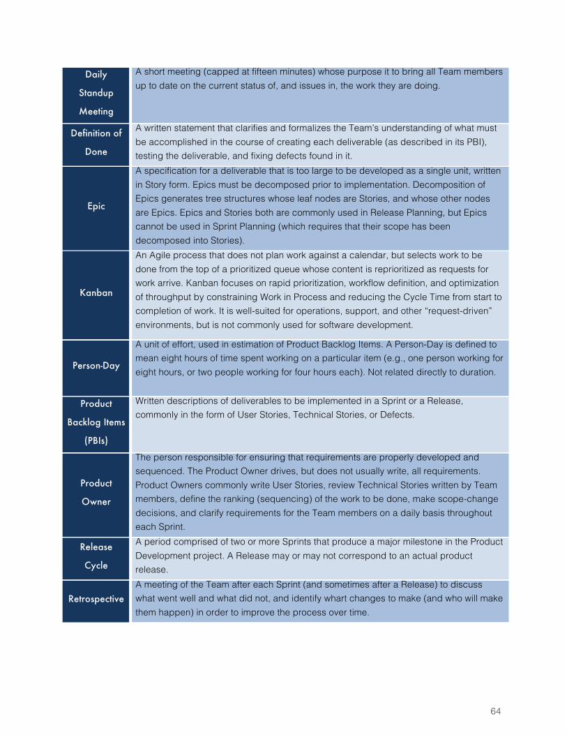
64
Daily
Standup
Meeting
A short meeting (capped at fifteen minutes) whose purpose it to bring all Team members up to date on the current status of, and issues in, the work they are doing.
Definition of
Done
A written statement that clarifies and formalizes the Team’s understanding of what must be accomplished in the course of creating each deliverable (as described in its PBI), testing the deliverable, and fixing defects found in it.
Epic
A specification for a deliverable that is too large to be developed as a single unit, written in Story form. Epics must be decomposed prior to implementation. Decomposition of Epics generates tree structures whose leaf nodes are Stories, and whose other nodes are Epics. Epics and Stories both are commonly used in Release Planning, but Epics cannot be used in Sprint Planning (which requires that their scope has been decomposed into Stories).
Kanban
An Agile process that does not plan work against a calendar, but selects work to be done from the top of a prioritized queue whose content is reprioritized as requests for work arrive. Kanban focuses on rapid prioritization, workflow definition, and optimization of throughput by constraining Work in Process and reducing the Cycle Time from start to completion of work. It is well-suited for operations, support, and other “request-driven” environments, but is not commonly used for software development.
Person-Day
A unit of effort, used in estimation of Product Backlog Items. A Person-Day is defined to mean eight hours of time spent working on a particular item (e.g., one person working for eight hours, or two people working for four hours each). Not related directly to duration.
Product
Backlog Items
(PBIs)
Written descriptions of deliverables to be implemented in a Sprint or a Release, commonly in the form of User Stories, Technical Stories, or Defects.
Product
Owner
The person responsible for ensuring that requirements are properly developed and sequenced. The Product Owner drives, but does not usually write, all requirements. Product Owners commonly write User Stories, review Technical Stories written by Team members, define the ranking (sequencing) of the work to be done, make scope-change decisions, and clarify requirements for the Team members on a daily basis throughout each Sprint.
Release
Cycle
A period comprised of two or more Sprints that produce a major milestone in the Product Development project. A Release may or may not correspond to an actual product release.
Retrospective A meeting of the Team after each Sprint (and sometimes after a Release) to discuss what went well and what did not, and identify whart changes to make (and who will make them happen) in order to improve the process over time.
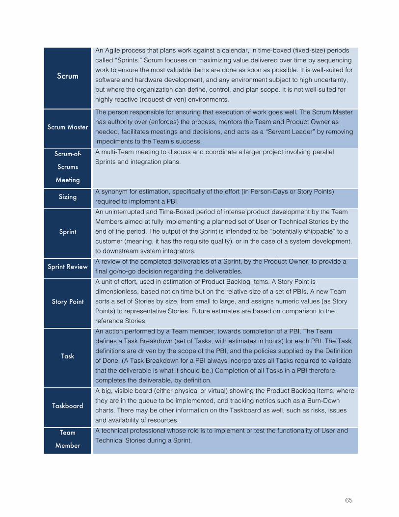
65
Scrum
An Agile process that plans work against a calendar, in time-boxed (fixed-size) periods called “Sprints.” Scrum focuses on maximizing value delivered over time by sequencing work to ensure the most valuable items are done as soon as possible. It is well-suited for software and hardware development, and any environment subject to high uncertainty, but where the organization can define, control, and plan scope. It is not well-suited for highly reactive (request-driven) environments.
Scrum Master
The person responsible for ensuring that execution of work goes well. The Scrum Master has authority over (enforces) the process, mentors the Team and Product Owner as needed, facilitates meetings and decisions, and acts as a “Servant Leader” by removing impediments to the Team's success.
Scrum-of-
Scrums
Meeting
A multi-Team meeting to discuss and coordinate a larger project involving parallel Sprints and integration plans.
Sizing A synonym for estimation, specifically of the effort (in Person-Days or Story Points) required to implement a PBI.
Sprint
An uninterrupted and Time-Boxed period of intense product development by the Team Members aimed at fully implementing a planned set of User or Technical Stories by the end of the period. The output of the Sprint is intended to be “potentially shippable” to a customer (meaning, it has the requisite quality), or in the case of a system development, to downstream system integrators.
Sprint Review A review of the completed deliverables of a Sprint, by the Product Owner, to provide a final go/no-go decision regarding the deliverables.
Story Point
A unit of effort, used in estimation of Product Backlog Items. A Story Point is dimensionless, based not on time but on the relative size of a set of PBIs. A new Team sorts a set of Stories by size, from small to large, and assigns numeric values (as Story Points) to representative Stories. Future estimates are based on comparison to the reference Stories.
Task
An action performed by a Team member, towards completion of a PBI. The Team defines a Task Breakdown (set of Tasks, with estimates in hours) for each PBI. The Task definitions are driven by the scope of the PBI, and the policies supplied by the Definition of Done. (A Task Breakdown for a PBI always incorporates all Tasks required to validate that the deliverable is what it should be.) Completion of all Tasks in a PBI therefore completes the deliverable, by definition.
Taskboard
A big, visible board (either physical or virtual) showing the Product Backlog Items, where they are in the queue to be implemented, and tracking netrics such as a Burn-Down charts. There may be other information on the Taskboard as well, such as risks, issues and availability of resources.
Team
Member
A technical professional whose role is to implement or test the functionality of User and Technical Stories during a Sprint.
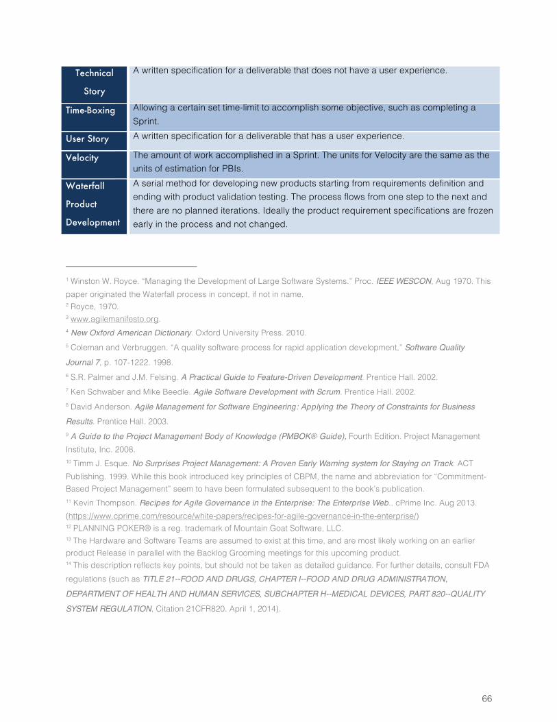
66
Technical
Story
A written specification for a deliverable that does not have a user experience.
Time-Boxing Allowing a certain set time-limit to accomplish some objective, such as completing a Sprint.
User Story A written specification for a deliverable that has a user experience.
Velocity The amount of work accomplished in a Sprint. The units for Velocity are the same as the units of estimation for PBIs.
Waterfall
Product
Development
A serial method for developing new products starting from requirements definition and ending with product validation testing. The process flows from one step to the next and there are no planned iterations. Ideally the product requirement specifications are frozen early in the process and not changed.
1 Winston W. Royce. “Managing the Development of Large Software Systems.” Proc. IEEE WESCON, Aug 1970. This paper originated the Waterfall process in concept, if not in name. 2 Royce, 1970. 3 www.agilemanifesto.org. 4 New Oxford American Dictionary. Oxford University Press. 2010. 5 Coleman and Verbruggen. “A quality software process for rapid application development,” Software Quality
Journal 7, p. 107-1222. 1998. 6 S.R. Palmer and J.M. Felsing. A Practical Guide to Feature-Driven Development. Prentice Hall. 2002. 7 Ken Schwaber and Mike Beedle. Agile Software Development with Scrum. Prentice Hall. 2002. 8 David Anderson. Agile Management for Software Engineering: Applying the Theory of Constraints for Business
Results. Prentice Hall. 2003. 9 A Guide to the Project Management Body of Knowledge (PMBOK® Guide), Fourth Edition. Project Management Institute, Inc. 2008. 10 Timm J. Esque. No Surprises Project Management: A Proven Early Warning system for Staying on Track. ACT Publishing. 1999. While this book introduced key principles of CBPM, the name and abbreviation for “Commitment-Based Project Management” seem to have been formulated subsequent to the book’s publication. 11 Kevin Thompson. Recipes for Agile Governance in the Enterprise: The Enterprise Web.. cPrime Inc. Aug 2013. (https://www.cprime.com/resource/white-papers/recipes-for-agile-governance-in-the-enterprise/) 12 PLANNING POKER® is a reg. trademark of Mountain Goat Software, LLC. 13 The Hardware and Software Teams are assumed to exist at this time, and are most likely working on an earlier product Release in parallel with the Backlog Grooming meetings for this upcoming product. 14 This description reflects key points, but should not be taken as detailed guidance. For further details, consult FDA regulations (such as TITLE 21--FOOD AND DRUGS, CHAPTER I--FOOD AND DRUG ADMINISTRATION,
DEPARTMENT OF HEALTH AND HUMAN SERVICES, SUBCHAPTER H--MEDICAL DEVICES, PART 820--QUALITY
SYSTEM REGULATION, Citation 21CFR820. April 1, 2014).