CprE 288 – Introduction to Embedded Systems...
47
CprE 288 – Introduction to Embedded Systems (Timers/Input Capture) 1 Instructors: Dr. Phillip Jones
Transcript of CprE 288 – Introduction to Embedded Systems...

CprE 288 – Introduction to Embedded Systems (Timers/Input Capture)
1
Instructors:
Dr. Phillip Jones
Announcements
• HW6: Due Sunday 10/15 (midnight)
• Exam 2: In class Thursday 11/9
• This week lab will use an Ultra sound
• Textbook reading: Section 9.1, 9.2
2 http://class.ece.iastate.edu/cpre288
Overview of Today’s Lecture
• Input Capture Review –Textbook reading: Section 9.1, 9.2
3 http://class.ece.iastate.edu/cpre288

INPUT CAPTURE
http://class.ece.iastate.edu/cpre288 4

5
Input Capture
Capture the times of events Many applications in microcontroller applications:
– Measure rotation rate – Remote control – Sonar devices – Communications
Generally, any input that can be treated as a series of events, where the precise measure of event times is important
http://class.ece.iastate.edu/cpre288

6
for lab 7 we use
T3CCP1
Which uses
TIMER3B, and Pin 3
of Port B
http://class.ece.iastate.edu/cpre288
TIVA TM4C123GH6PM CCP (Capture/Compare/PWM)
Timer Diagram
(More on pages 704-707 of datasheet)

7
Input Capture
An event is a transition of binary signal
Example: How many events make up the following waveform?
http://class.ece.iastate.edu/cpre288

8
Input Capture
An input digitalized and then times captured
Example: The input is understood as events occurring at the following times: 220, 221, 223, 226, and 227 with initial state as low
http://class.ece.iastate.edu/cpre288

Application: Speedometer
http://class.ece.iastate.edu/cpre288 9
How to detect the speed of a treadmill?
Magnet sensor Microcontroller
Waveform

10
Application: Sonar Device
Ping))) sensor: ultrasound
distance detection device
http://class.ece.iastate.edu/cpre288

11
Sonar Principle
Sound Speed in Lab Temperature: About 340m/s
Pulse width proportional to round-trip distance
* Temperature affects sound speed
http://class.ece.iastate.edu/cpre288

12
Sonar Principle
Time Diff. Clock Count One-way Distance
2ms 125 0.34m
4ms 250 0.68m
Assume 62.5KHz Input Capture clock
1ms <=> 62.5 clocks <=> 34cm
How to capture the times of rising edge and falling edge?
http://class.ece.iastate.edu/cpre288

13
Application: Remote Control (Decoding)
http://class.ece.iastate.edu/cpre288
14
Input Capture: Design Principle
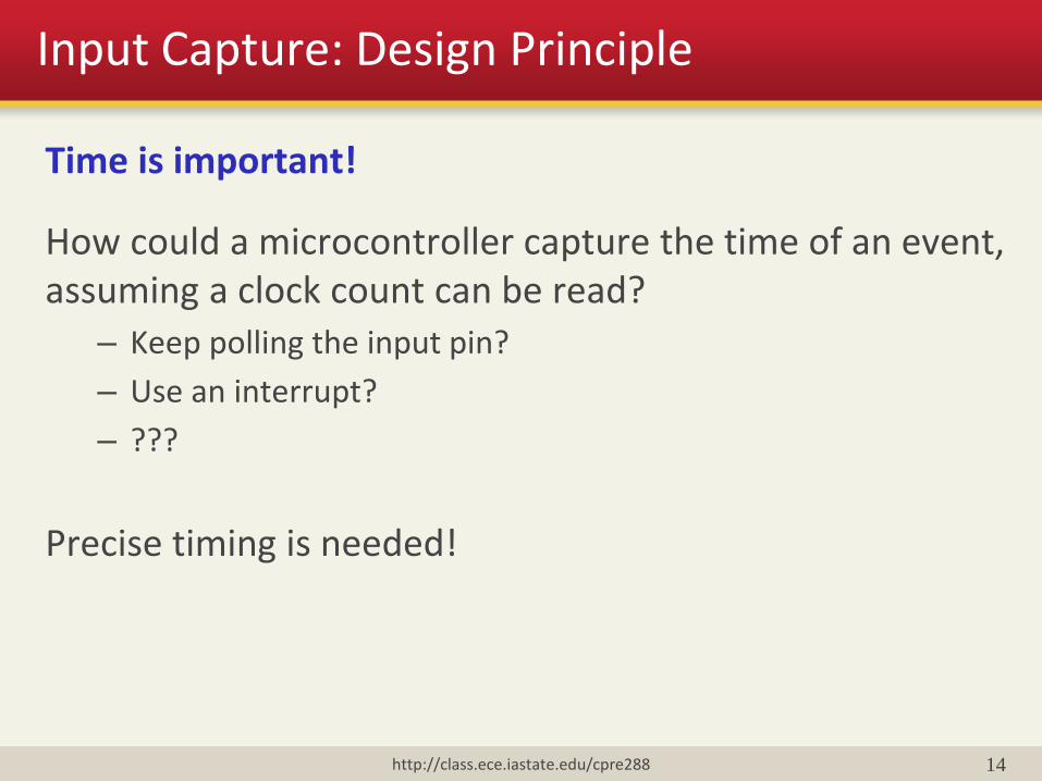
Time is important!
How could a microcontroller capture the time of an event, assuming a clock count can be read?
– Keep polling the input pin?
– Use an interrupt?
– ???
Precise timing is needed!
http://class.ece.iastate.edu/cpre288

15
Input Capture: Design Principle
Time value (clock count) is captured first then read by the CPU
GPTMTnV
GPTMTnR Edge
Detector Noise
Canceller
GPTMTnV: Timer n Value Register (n is A or B)
GPTMTnR: Timer Register (in Edge-Time mode, this register is
loaded with the value in GPTMTnV at the last input edge event)
To CPU
Interrupt
http://class.ece.iastate.edu/cpre288

Input Capture: Design Principle
What happens in hardware and software when and after an event occurs
• The event’s time is captured in the GPTMTnR (timer register)
• An interrupt is raised to the CPU
• CPU executes the input capture ISR, which reads the timer register and completes the related processing
The captured time is precise because it’s captured immediately when the event occurs
The ISR should read the timer register and complete its processing fast enough to avoid loss of events
16

17
Input Capture: Design Principle
Interrupt
CPU Interrupt
processing
CPU Foreground
computation
http://class.ece.iastate.edu/cpre288

18
Input Capture: Design Principle
How to program the interrupt handler to – Count the number of pulses – Calculate pulse width – Decode IR signals – And do many other functions …
IntRegister(INT_TIMER3B, TIMER3B_Handler); //in main void TIMER3B_Handler(void) { // YOUR PROCESSING }
http://class.ece.iastate.edu/cpre288

19
Tiva TM4C123GH6PM 16/32-bit Timer as Input Capture Unit
Tiva TM4C123GH6PM has 6, multi-purpose 16/32-bit timer units with – Input capture units (IC)
– Output compare units (OC)
– Pulse width modulation output (PWM)
– And other features
http://class.ece.iastate.edu/cpre288

20
for lab 7 we use
T3CCP1
Which uses
TIMER3B, and Pin 3
of Port B
http://class.ece.iastate.edu/cpre288
TIVA TM4C123GH6PM CCP (Capture/Compare/PWM)
Timer Diagram
(More on pages 704-707 of datasheet)

21
Tiva TM4C123GH6PM 16/32-bit Timer as Input Capture Unit
When an edge is detected at input capture pin, current TIMERx_TnV_R (GPTMTnV) value is captured (saved) into TIMERx_TnR_R (GPTMTnR)
Time is captured immediately (when an event happens)
and read by the CPU later
http://class.ece.iastate.edu/cpre288

22
Use Input Capture: Example
int last_event_time; int main(void){
//configurations and inits IntRegister(INT_TIMER3B, TIMER3B_Handler); } void TIMER3B_Handler(void) { int event_time = TIMER3_TBR_R; // read current event time // YOUR PROCESSING CODE } Notes:
– Use Interrupt to process input capture events – Read captured time from TIMER3_TBR_R
http://class.ece.iastate.edu/cpre288

23
Lab 7 General Idea of Programming
General idea: – Configure Timer3B for input capture
– Generate a pulse to activate the PING))) sensor
– Capture the time of rising edge event
– Capture the time of falling edge event
– Calculate time difference and then distance to any object
http://class.ece.iastate.edu/cpre288

Application: Sonar Device
PING Sensor Datasheet:
• http://class.ece.iastate.edu/cpre288/resources/docs/28015-PING-v1.3.pdf
http://class.ece.iastate.edu/cpre288 24

25
Lab 7 General Idea of Programming
PB3 = 0
PB3 = 1
PB3 Config for output
PB3 Config for intput
5us minimum
Catch rising edge (store TIMER3_TBR_R in a var)
Catch falling edge (store TIMER3_TBR_R
in a var)
Send trigger
Change to GPIO mode before sending trigger pulse
Change to Input Capture mode after sending trigger pulse
Remember only one pin (i.e PB3) used to communicate with the PING))) sensor
http://class.ece.iastate.edu/cpre288

26
Timer Programming Interface
GPTMCTL: GPTM (General Purpose Timer) Control
GPTMCFG: GPTM Configuration
GPTMTnMR: GPTM Timer n Mode (n is A or B)
GPTMTnILR: GPTM Timer n Interval Load
GPTMIMR: GPTM Interrupt Mask Register
GPTMMIS: GPTM Masked Interrupt Status
GPTMICR: GPTM Interrupt Clear Register
http://class.ece.iastate.edu/cpre288

27
Textbook & Data Sheet: Read and ask questions
http://class.ece.iastate.edu/cpre288
• Exam 2 will predominantly consist of questions of the form – Program Configure Registers to meet these specs
• UART, ADC, Input Capture, Output Compare, Timers, Interrupts • Each device has a section in the Datasheet and Textbook
– Based on a given configuration, answer questions about how the
program will behave • E.g. How long will something take to occur? • E.g. How many time a second with something occur?
– Explain why a given configuration is incorrect for implementing a
specified behavior – Assuming a given configuration, write a short program to
implement a specific behavior – ADC calculation problem

16-bit Timer Programming Interface
Inside GPTMCTL:
TnPWML 6, 14 (A, B): PWM Output Level
TnOTE 5, 13 (A, B): Output trigger enable
TnEVENT 3:2, 11:10 (A, B): Event Mode (Edge Select)
TnSTALL 1, 9 (A, B): Timer n Stall Enable
TnEN 0, 8 (A, B): Timer n Enable
RTCEN 4 : RTC Stall Enable
28 http://class.ece.iastate.edu/cpre288

29
TnEVENT: GPTM Timer n Event Mode – Which edge will trigger an interrupt?
00: Positive (rising) edge 01: Negative (falling) edge 10: Reserved 11: Both TnEN: GPTM Timer n Enable Bit – Set this bit to enable Timer n. Make sure a timer is disabled before trying to change its
settings. (from p. 737 of datasheet)
http://class.ece.iastate.edu/cpre288
GPTMCTL (TIMERx_CTL_R)

30
GPTMCFG: GPTM Configuration 0x0: “Concatenated” mode. (16/32 bit timers use 32 bits,
32/64 bit timers use 64 bits.) 0x1: Concatenated mode, and timers are set to RTC (real-
time clock) counter configuration. 0x4: 16/32 bit timers are spilt into two 16-bit timers, timer A
and timer B. 32/64 bit timers are split into two 32-bit timers. Other values for GPTMCFG: are reserved.
(p. 727 of datasheet)
http://class.ece.iastate.edu/cpre288
GPTMCFG (TIMERx_CFG_R)

31 http://class.ece.iastate.edu/cpre288
GPTMTnMR (TIMERx_TnMR_R)
GPTMTnMR: GPTM Timer n Mode – Controls Timer mode. When in concatenated mode, GPTMTAMR controls the concatenated timer and GPTMTBMR is ignored.
TnMR: Timer n Mode 0x0: Reserved 0x1: One-Shot Timer Mode 0x2: Periodic Timer Mode 0x3: Capture Mode (p. 729 (Timer A) & 733 (Timer B) of datasheet)

32
TM4C123 Clock Sources
http://class.ece.iastate.edu/cpre288

33
When timer n is counting up GPTMTnILR contains the upper bound. When counting down GPTMTnILR contains the initial value for timer n.
Important Note: In lab 7, if TIMER3_TBILR_R is set to the max 0xFFFF (default), then the prescalar register (TIMER3_TBPS_R) will concatenate with the timer value register to make a 24-bit register. To get the correct values you must read from both TIMER3_TBPS_R & TIMER3_TBR_R and shift accordingly. TIMER3_TBPS_R is the most significant 8 bits in the 24 bit register. (p. 757, 761, 770)
http://class.ece.iastate.edu/cpre288
GPTMTnILR (TIMERx_TnILR_R)

34
For any interrupt in GPTMIMR write to the corresponding bit:
0 to disable the interrupt 1 to enable the interrupt
CnEIM: Timer n Capture Mode Event Interrupt Mask (p. 745 of datasheet)
http://class.ece.iastate.edu/cpre288
GPTMIMR (TIMERx_IMR_R)
35
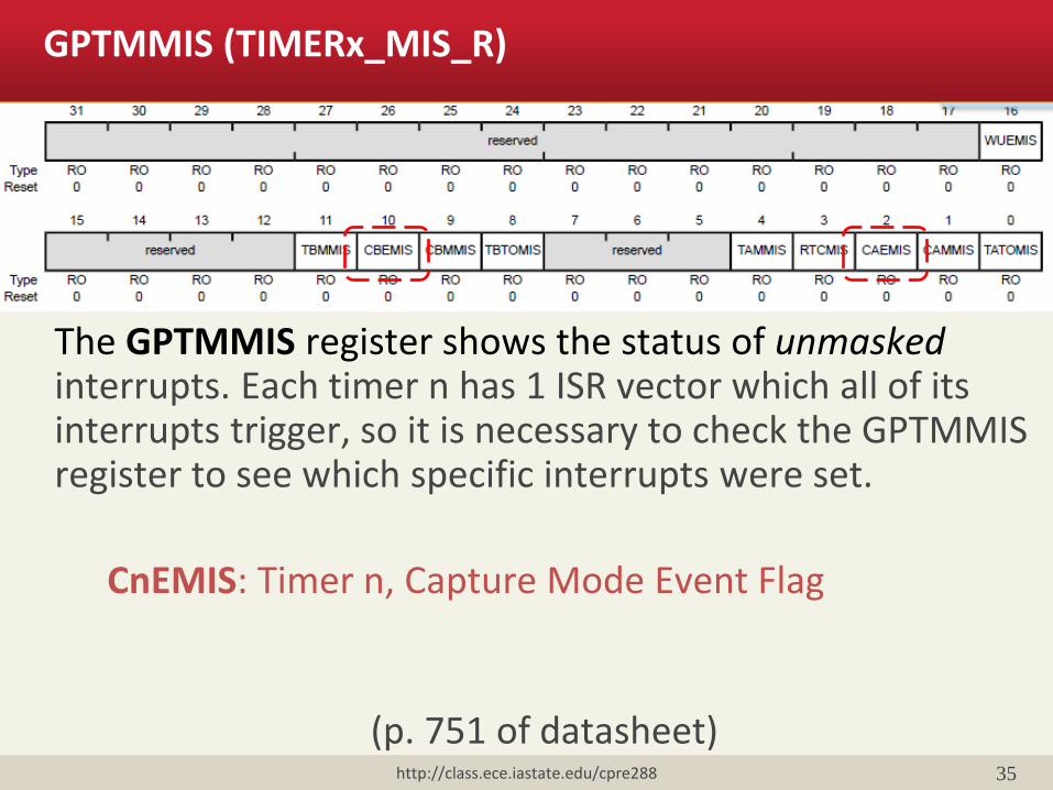
The GPTMMIS register shows the status of unmasked interrupts. Each timer n has 1 ISR vector which all of its interrupts trigger, so it is necessary to check the GPTMMIS register to see which specific interrupts were set.
CnEMIS: Timer n, Capture Mode Event Flag
(p. 751 of datasheet)
http://class.ece.iastate.edu/cpre288
GPTMMIS (TIMERx_MIS_R)

36
To clear an interrupt flag write a 1 to the corresponding bit in GPTMICR. CnECINT: Clears the Timer n Capture Mode Event Flag
(p. 754 of datasheet)
http://class.ece.iastate.edu/cpre288
GPTMICR (TIMERx_ICR_R)

37
Configure Timer3B for Lab 7
TIMER3_CTL_R: Enable, Edge Select. TIMER3_CFG_R: 16-bit mode. TIMER3_TBMR_R: Capture Mode, Edge-Time Mode, Count up. TIMER3_TBILR_R: Set upper bound. TIMER3_IMR_R: Enable capture interrupt.
Port B pin 3 (PB3) – It is Timer3B’s Capture/Compare/PWMv (CCP) pin, and connects to the input/output pin of the PING sensor
http://class.ece.iastate.edu/cpre288
38
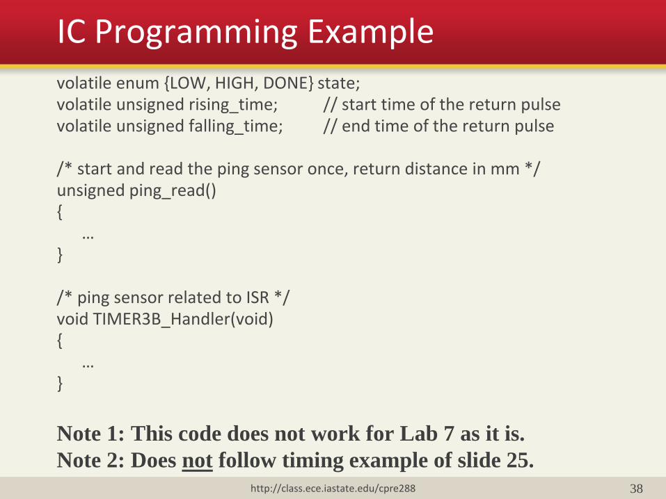
IC Programming Example volatile enum {LOW, HIGH, DONE} state; volatile unsigned rising_time; // start time of the return pulse volatile unsigned falling_time; // end time of the return pulse /* start and read the ping sensor once, return distance in mm */ unsigned ping_read() { … } /* ping sensor related to ISR */ void TIMER3B_Handler(void) { … } Note 1: This code does not work for Lab 7 as it is.
Note 2: Does not follow timing example of slide 25. http://class.ece.iastate.edu/cpre288

39
/* send out a pulse on PB3 */ void send_pulse() { GPIO_PORTB_DIR_R |= 0x08; // set PB3 as output GPIO_PORTB_DATA_R |= 0x08; // set PB3 to high // wait at least 5 microseconds based on data sheet GPIO_PORTB_DATA_R &= 0xF7; // set PB3 to low GPIO_PORTB_DIR_R &= 0xF7; // set PB3 as input } /* convert time in clock counts to single-trip distance in mm */ unsigned time2dist(unsigned time) { … }
http://class.ece.iastate.edu/cpre288
Note 1: This code does not work for Lab 7 as it is.
Note 2: Does not follow timing example of slide 25.

40
unsigned ping_read() { send_pulse(); // send the starting pulse to PING // TODO get time of the rising edge of the pulse // TODO get time of the falling edge of the pulse // Calculate the width of the pulse; convert to centimeters }
http://class.ece.iastate.edu/cpre288

ADD-ON SLIDES
http://class.ece.iastate.edu/cpre288 41
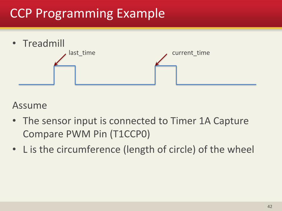
CCP Programming Example
• Treadmill
Assume
• The sensor input is connected to Timer 1A Capture Compare PWM Pin (T1CCP0)
• L is the circumference (length of circle) of the wheel
42
last_time current_time

CCP Programming Example
volatile unsigned last_time = 0;
volatile unsigned current_time = 0;
volatile int update_flag = 0;
// ISR: Record the current event time
void TIMER1A_Handler(void)
{
last_time = current_time;
current_time = TIMER1_TAR_R;
update_flag = 1;
}
Recall: We have to declare “volatile” for global variables
changed by ISRs, otherwise a normal function may not see
the changes
43
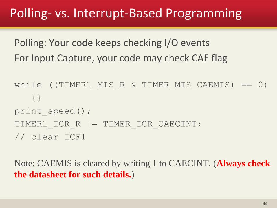
Polling- vs. Interrupt-Based Programming
Polling: Your code keeps checking I/O events
For Input Capture, your code may check CAE flag
while ((TIMER1_MIS_R & TIMER_MIS_CAEMIS) == 0)
{}
print_speed();
TIMER1_ICR_R |= TIMER_ICR_CAECINT;
// clear ICF1
Note: CAEMIS is cleared by writing 1 to CAECINT. (Always check
the datasheet for such details.)
44

Polling- vs. Interrupt-Based Programming
Why polling?
Program control flow looks simple
Interrupts have overheads added to the processing delay
Not every programmer likes writing ISRs
Why NOT polling?
The CPU cannot do anything else
The CPU cannot sleep to save power
Using ISRs can simplify the control structure of the main program
45
Overflow
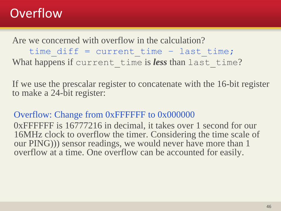
Are we concerned with overflow in the calculation?
time_diff = current_time – last_time;
What happens if current_time is less than last_time?
If we use the prescalar register to concatenate with the 16-bit register to make a 24-bit register:
Overflow: Change from 0xFFFFFF to 0x000000
0xFFFFFF is 16777216 in decimal, it takes over 1 second for our 16MHz clock to overflow the timer. Considering the time scale of our PING))) sensor readings, we would never have more than 1 overflow at a time. One overflow can be accounted for easily.
46

Overflow
unsigned long time_diff;
overflow += (current_time < last_time);
time_diff = ((unsigned long)overflow<<24)
+ current_time – last_time;
update_flag = 0;
• Overflow occurred if current_time < last_time
• For each overflow, increase time_diff by 16,777,216 (224)
• You have to use long integer which is 32-bit (0 to 232-1)
47