CPA-SC Valve Manifold - Festo · Features and Benefits CPA-SC Valve Manifold with DeviceNet...
68
CPA-SC Valve Manifold Modularity with High Performance CPA-SC Valves Valve width: 10 mm Flow rate: up to 0.15 Cv (150 l/min) 2/2-way, 3/2-way, 5/2-way and 5/3-way valve functions Inch and metric tubing connections CPA-SC Manifolds with Multipin Connection Compact, for tight envelope constraints IP40 rated (in assembled state with detented plug) 25 pin Sub-D or 26 pin flat cable connector 4 to 20 positions on a manifold CPA-SC Manifolds with Fieldbus Connection Comply with ODVA specifications IP40 rated (with covered control elements) Advanced diagnostic functions for easy maintenance CP extension, for an additional 16 I/O signals Info 211 US
-
Upload
trinhtuyen -
Category
Documents
-
view
221 -
download
1
Transcript of CPA-SC Valve Manifold - Festo · Features and Benefits CPA-SC Valve Manifold with DeviceNet...
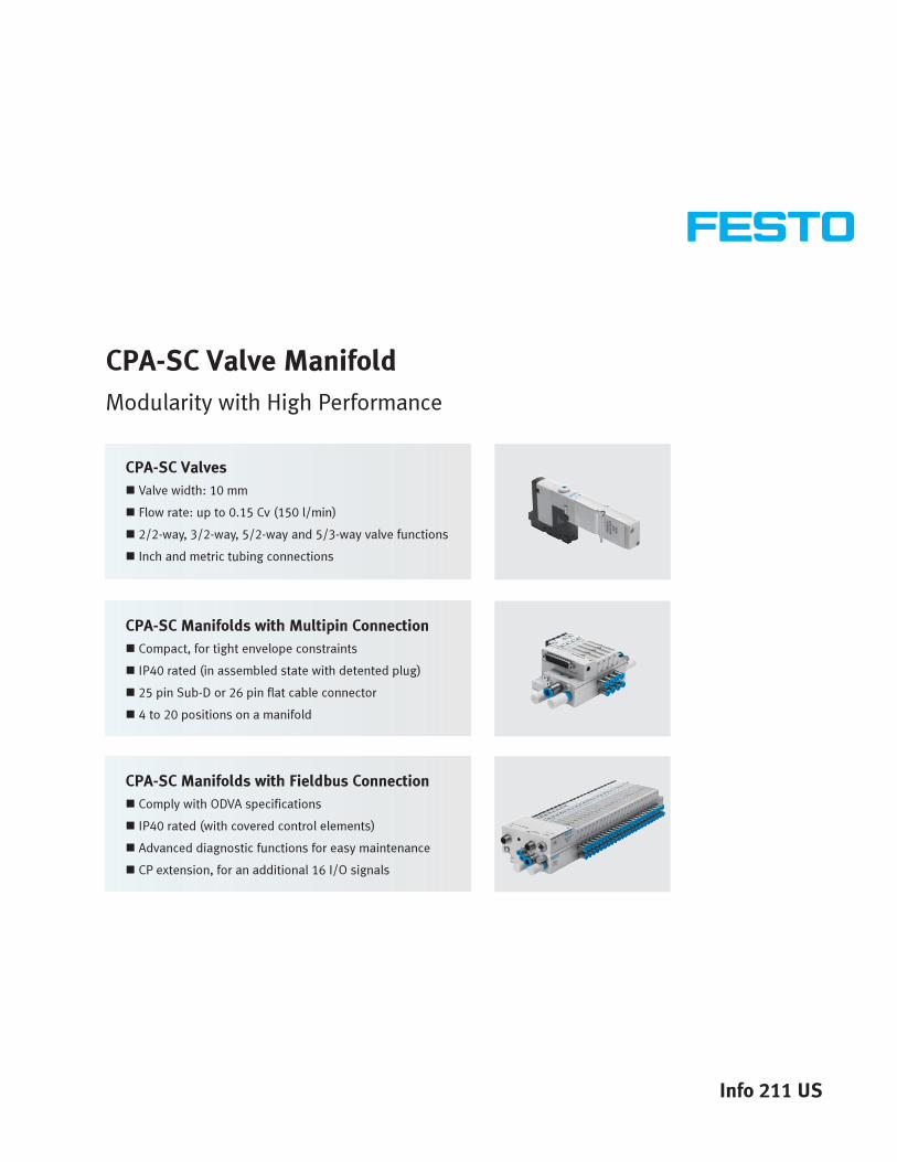
CPA-SC Valve Manifold
Modularity with High Performance
CPA-SC Valves
� Valve width: 10 mm
� Flow rate: up to 0.15 Cv (150 l/min)
� 2/2-way, 3/2-way, 5/2-way and 5/3-way valve functions
� Inch and metric tubing connections
CPA-SC Manifolds with Multipin Connection
� Compact, for tight envelope constraints
� IP40 rated (in assembled state with detented plug)
� 25 pin Sub-D or 26 pin flat cable connector
� 4 to 20 positions on a manifold
CPA-SC Manifolds with Fieldbus Connection
� Comply with ODVA specifications
� IP40 rated (with covered control elements)
� Advanced diagnostic functions for easy maintenance
� CP extension, for an additional 16 I/O signals
Info 211 US
Festo...Your AutomationPartner Worldwide
As a global leader in industrial
automation components and
systems, with over $1.8 billion
sales worldwide, Festo has
the resources and application
experience to be your long
term partner for cost-effective
automation solutions.
• 55 independent
subsidiaries worldwide
• Representation in
180 countries
• Worldwide networking for
consistent standards of
products, consultancy,
sales and services.
• Worldwide support provided
by over 11,000 team members
Festo Quality Assurance,ISO 9001 Certification
Festo Corporation
is committed to
provide Festo
products and
services that will
meet or exceed
our customers’
requirements in
product quality, delivery,
customer service and
satisfaction.
All Festo locations within the UnitedStates are registered to ISO 9001.
Online Literature
Literature in PDF format is
available for download at:
www.festo.com/us/CPASC
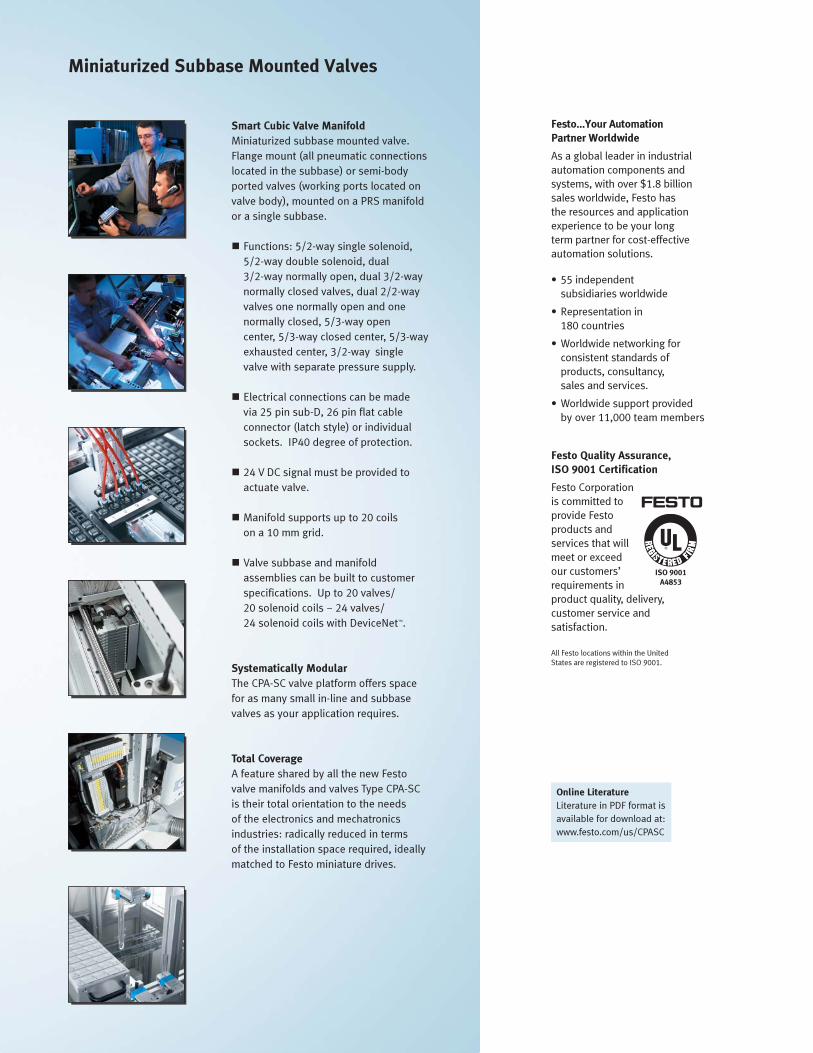
Miniaturized Subbase Mounted Valves
Smart Cubic Valve Manifold
Miniaturized subbase mounted valve.
Flange mount (all pneumatic connections
located in the subbase) or semi-body
ported valves (working ports located on
valve body), mounted on a PRS manifold
or a single subbase.
� Functions: 5/2-way single solenoid,
5/2-way double solenoid, dual
3/2-way normally open, dual 3/2-way
normally closed valves, dual 2/2-way
valves one normally open and one
normally closed, 5/3-way open
center, 5/3-way closed center, 5/3-way
exhausted center, 3/2-way single
valve with separate pressure supply.
� Electrical connections can be made
via 25 pin sub-D, 26 pin flat cable
connector (latch style) or individual
sockets. IP40 degree of protection.
� 24 V DC signal must be provided to
actuate valve.
� Manifold supports up to 20 coils
on a 10 mm grid.
� Valve subbase and manifold
assemblies can be built to customer
specifications. Up to 20 valves/
20 solenoid coils – 24 valves/
24 solenoid coils with DeviceNet™.
Systematically Modular
The CPA-SC valve platform offers space
for as many small in-line and subbase
valves as your application requires.
Total Coverage
A feature shared by all the new Festo
valve manifolds and valves Type CPA-SC
is their total orientation to the needs
of the electronics and mechatronics
industries: radically reduced in terms
of the installation space required, ideally
matched to Festo miniature drives.
02/2006 – Subject to change – Info 211 US – CPA-SC Type 82 Valve Manifolds 3
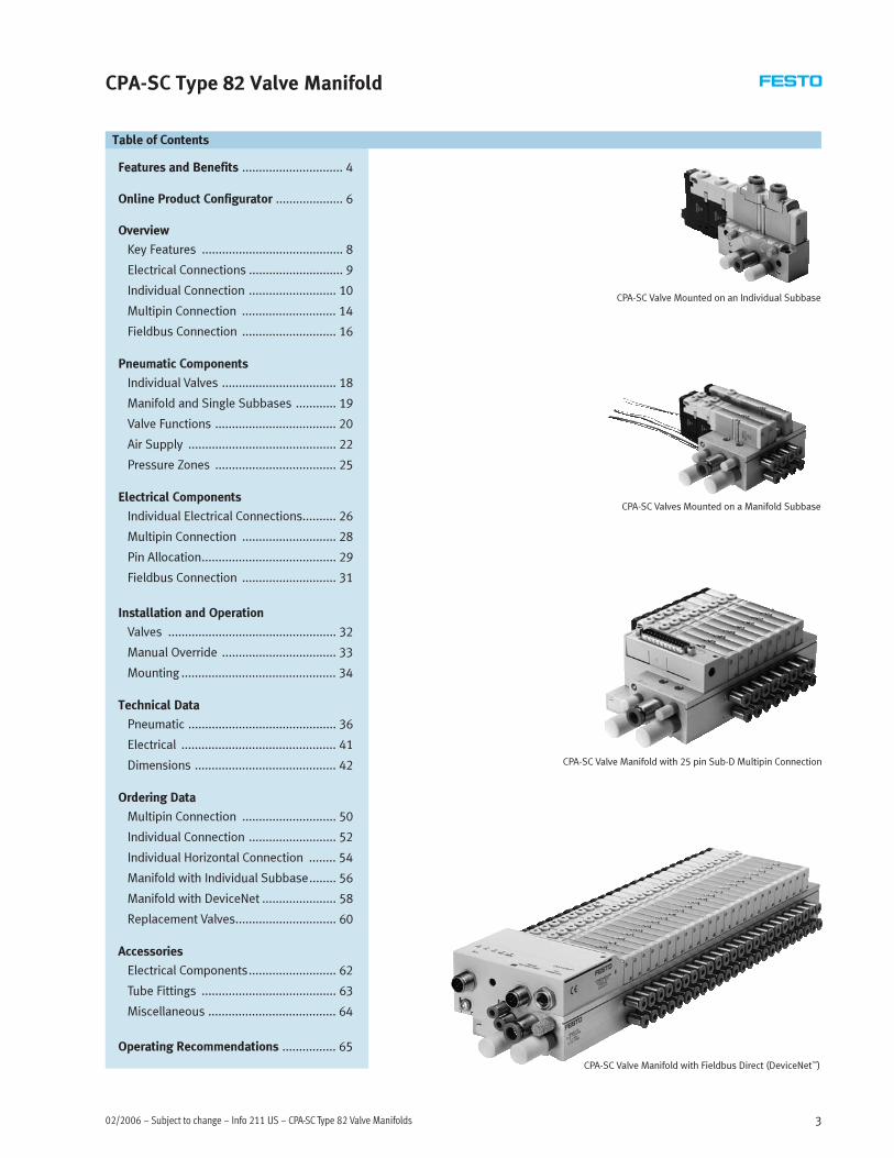
CPA-SC Type 82 Valve Manifold
Features and Benefits .............................. 4
Online Product Configurator .................... 6
Overview
Key Features .......................................... 8
Electrical Connections ............................ 9
Individual Connection .......................... 10
Multipin Connection ............................ 14
Fieldbus Connection ............................ 16
Pneumatic Components
Individual Valves .................................. 18
Manifold and Single Subbases ............ 19
Valve Functions .................................... 20
Air Supply ............................................ 22
Pressure Zones .................................... 25
Electrical Components
Individual Electrical Connections.......... 26
Multipin Connection ............................ 28
Pin Allocation........................................ 29
Fieldbus Connection ............................ 31
Installation and Operation
Valves .................................................. 32
Manual Override .................................. 33
Mounting .............................................. 34
Technical Data
Pneumatic ............................................ 36
Electrical .............................................. 41
Dimensions .......................................... 42
Ordering Data
Multipin Connection ............................ 50
Individual Connection .......................... 52
Individual Horizontal Connection ........ 54
Manifold with Individual Subbase........ 56
Manifold with DeviceNet ...................... 58
Replacement Valves.............................. 60
Accessories
Electrical Components.......................... 62
Tube Fittings ........................................ 63
Miscellaneous ...................................... 64
Operating Recommendations ................ 65
Table of Contents
CPA-SC Valves Mounted on a Manifold Subbase
CPA-SC Valve Mounted on an Individual Subbase
CPA-SC Valve Manifold with Fieldbus Direct (DeviceNet™)
CPA-SC Valve Manifold with 25 pin Sub-D Multipin Connection

Features and Benefits
CPA-SC Type 82 Valve Manifold – Info 211 US – Subject to change – 02/20064
� Manual override facility
� Durable thanks to the use
of tried-and-tested piston
spool valves
� Sturdy thanks to metal
housing and connecting thread
� Fast troubleshooting thanks
to LEDs on the valves and
diagnosis via fieldbus
� Festo enables designers
to incorporate product
into their machines
avoiding major redesigns
� Catalog specifications reflect
true product capability
� Easy product selection
� Ready-to-install, and
tested manifold
� Room for expansion with
2 to 24 valve positions on
one manifold
� Use of individual valves
in combination with an
individual subbase
� Low operating costs
� Easy to design:
2D or 3D CAD support
� Technical support and
comprehensive product
documentation
� Compact size
� High flow/size ratio
� A wide range of mounting
types (semi-body ported
valves, single subbases and
manifold subbases) offer the
customer a high degree of
flexibility in machine design
� Dual valve slices (for example,
two 3/2-way valves in a single
plate) and all other basic
valves (5/2-way and 5/3-way)
� Can choose direction of
connectors (from above or
from the side)
� When necessary, it is very
easy to exchange valves
Flexible Reliable Easy
� Components, assemblies
or systems from one source
to the customer which
provides for a simplified
and more cost efficient
procurement of supplies
� Easy to convert, expand,
or replace
� Convenient labeling system
� Rapid error detection
with integrated diagnostics
� Straightforward valve
replacement
� Replaceable electronics
Installation and Maintenance
� Simple connection of
pneumatic and electrical
components to an
automated system
� Easy diagnostics and
maintenance
� Flow rate up to 0.15 Cv
(150 l/min)
� 2/2-way, 3/2-way, 5/2-way,
5/3-way valve functions
� IP40 rated
� Modular and flexible
Overview
� Reliable and durable
� Competitive pricing

Features and Benefits
CPA-SC Valve Manifold with DeviceNet Fieldbus Connection
Control Architecture Electrical Connections
Reduced Downtimes
LEDs indicate the operating status
Control elements
Fieldbus connector
(DeviceNet)
CP connection
Power supply
CPA-SC DeviceNet
DFM-12-40
CP-E16-KL-CL CP-A04-M12-CL
CP-E08-M8-CL CP-A04-M12-CL
CP-A08-M12 CP-A16-M8
or
or
Simple Electrical Connections
Sub-D plug or flat cable as well
as horizontal connector (HC) or
downward plug-in connector
Quick Mounting
Directly mounted using
screws or DIN rail
Duct Separation
Creates additional pressure
zones without malfunctions
using a separate exhaust air line
Space-saving Design
Grid 40x10 mm, max. 20 valves
Reliable Operation
Manual override push-in/
detenting or covered
Easy Valve Replacement
Valves attached via 2 screws
Reliable
Valve mounting on manifold block
Practical Connection
Sturdy metal thread or
QS push-in fittings
Selectable
Pneumatic outlets
Width:
10 mm
� �
02/2006 – Subject to change – Info 211 US – CPA-SC Type 82 Valve Manifolds 5

CPA-SC Type 82 Valve Manifolds – Info 211 US – Subject to change – 02/20066
Online Product ConfiguratorCPA-SC Type 82 Valve Manifolds
FACE Configurator Electronic Catalog at www.festo.com/us
A valve manifold configurator is
available to help you configure a
suitable CPA-SC valve manifold.
The valve manifolds are fully
assembled according to your order
specifications and individually tested.
This reduces the amount of assembly
and installation required to a
minimum.
A type 82 valve manifold is ordered
via a modular order code.
The ordering system for valve
manifolds starts on page 50.
The illustration above provides an example of a valve manifold configuration.
The following steps explain how you
use FACE to arrive at the order code.
Once you have called up the Festo
home page, select the online version
of the digital product catalog from the
“Products” submenu: this will bring
you directly to the home page for the
Pneumatic Catalog. Activate the
“Direct Search” menu.
Here you can specify a “Part No.”
(e.g. 529045), “Type” (e.g. CPASC1) or
“Article designation” (e.g. valve
manifold) to find your “Search result”.
Click on the blue shopping basket to
complete the selected product
according to your specifications (this
does not initiate an order).
You will then be prompted to
configure the product. Select
“Configurator”.
You can then configure the valve
manifold step by step (from the top
down) according to your requirements.
Select the “Finish” menu to continue
on with the ordering process.

Compact size(valve width 10 mm)
Flow rate up to 0.15 Cv (150 l/min)
High flow/size ratio
Ready-to-install, tested manifold
Multipin and fieldbusconnections
CPA-SC Type 82 Valve Manifolds
02/2006 – Subject to change – Info 211 US – CPA-SC Type 82 Valve Manifolds 7

CPA-SC Type 82 Valve Manifolds – Info 211 US – Subject to change – 02/20068
OverviewKey Features
Valve Manifold
Reduced downtimes:
LEDs indicate the operating status
Reliable operation:
Manual override push-in/detenting or covered
Width: 10 mm
Simple electrical connections:
Individual valve connection,
multi-pin plug connection or
fieldbus connection via
Fieldbus Direct
Quick mounting:
Directly mounted using screws or DIN rail
Easy valve replacement:
Valves with screw connection
Space-saving thanks to 2 … 24
valve positions
Reliable valve mounting system
Practical:
Durable metal thread or
easy-to-use QS push-in fittings
Choice of pneumatic outlets
Comprehensive valve functions
Valve Functions
� 5/2-way valve, single solenoid
� 5/2-way valve, double solenoid
� 2x 3/2-way valve,
normally open
� 2x 3/2-way valve,
normally closed
� 5/3-way valve,
mid-position pressurized
� 5/3-way valve,
mid-position closed
� 5/3-way valve,
mid-position exhausted
� 1x 3/2-way valve,
normally closed, external
compressed air supply
� 2x 2/2-way valve,
normally closed, dual
compressed air supply
All valves have the same compact
dimensions with an overall length of
91 mm and a width of 10 mm. Valves
with a height of 40 mm are available
for applications requiring particularly
flat variants.
Electrical Connection Options
Individual Connection
� Plug-in (PI)
�Horizontal connection (HC)
Individual Subbase Valve
� Plug-in (PI)
�Horizontal connection (HC)
Multipin
�Max. 20 valve positions/
max. 20 solenoid coils
� Sub-D
� Flat cable
Fieldbus
�Max. 24 valve positions/
max. 32 solenoid coils

02/2006 – Subject to change – Info 211 US – CPA-SC Type 82 Valve Manifolds 9
OverviewElectrical Connections
Individual Connection
Connection is independent of the
control technology used. This ensures
correct polarity during installation.
The valve is equipped with an LED
which indicates switching status, and
an overvoltage protective circuit. It
also features a built-in current
reduction circuit.
Individual connection permits the
selection of 2 to 32 solenoid coils
(divided between 2 to 16 valve
positions, including in uneven
gradations).
Valves can also be used on a single
subbase for actuators further away
from the valve manifold.
With an individual electrical
connection, the plug is connected
directly to the valve. Two electrical
connection types are available for
the valve manifold and for the
single subbase:
�Horizontal connection (HC) or
� Plug-in (PI)
Version SH:
The electrical connection can be
plugged in directly on the valve.
Version SP, SQ:
The connector plug is mounted on an
adapter. This adapter is then attached
to the manifold.
Multipin Plug Connection
Control signals from the controller to
the valve manifold are transmitted via
a pre-assembled multi-core cable,
which substantially reduces
installation time.
These valve manifolds can be fitted
with 2 to 20 solenoid coils.
Variants
� Sub-D connection
� Flat cable connection
Fieldbus Direct
An integrated fieldbus node manages
the communication connection to a
higher-order PLC. This enables a
space-saving pneumatic and
electronic solution.
The fieldbus node is directly
integrated in the electrical interface of
the valve manifold and therefore takes
up only a minimal amount of space.
The CP string extension option allows
the functions and components of the
CP installation system to be used.
Valve manifolds with fieldbus
interfaces can be equipped with
4 to 24 valve positions and 4 to 32
solenoid coils.
Variants
� DeviceNet connection
� 4 to 32 solenoid coils
CP string Extension
The optional string extension allows
an additional valve manifold and I/O
modules to be connected to Fieldbus
Direct. A CP string of the CP
installation system is integrated in
the fieldbus node as an extension.
Different input and output modules as
well as CPV and CPA valve manifolds
can be connected.
The max. length of the CP string
extends to 10 meters, which means
that the extension modules can be
mounted directly on-site. All of the
required electrical signals are
transmitted via the CP cable, which in
turn means that no further
installation is needed on the
extension module.
The CP string interface offers:
� 16 input signals
� 16 output signals for 24 V DC
output modules or solenoid coils
� Logic and sensor supply for the
input modules
� Logic and sensor supply for the
output modules
� Load voltage supply for the valve
manifolds
� Logic supply for the output module
� See Fieldbus Direct Product
Guide (Info 201)
� See CP Valve Installation System
Product Guide (Info 221)

CPA-SC Type 82 Valve Manifolds – Info 211 US – Subject to change – 02/200610
OverviewIndividual Connection
Manifold with Subbase Valves and Indvidual Plug-in Electrical Connection (PI)
Order Codes: IP, IQ Valve manifolds with individual
plug-in electrical connections are
available in sizes for 2 to max. 16
valve positions. Each valve position
can either be equipped with a valve or
a blanking plate.
With an individual PI connection,
the connector plug remains on the
manifold block. This avoids the valve
being connected incorrectly in the
event of a recommissioning.
1
3
4
5
6
7
8
9
aJ
aA2
aA
1 Cover for manual override
(optional)
2 Manual override (per solenoid
coil, push-in/rotary-detenting)
3 Working lines (2, 4) on the
manifold block (per valve
position)
4 Supply ports (1, 12/14), exhaust
ports (3, 5, 82/84) and pressure
compensating port (L) on the
left-hand and right-hand side of
the manifold
5 Individual plug-in connection (PI)
6 Valve
7 Cover for spare position
(blanking plate)
8 Manifold block for subbase
valves
9 Connectors, silencers and
blanking plugs
aJ DIN rail mounting
aA Labels

02/2006 – Subject to change – Info 211 US – CPA-SC Type 82 Valve Manifolds 11
OverviewIndividual Connection
Manifold with Subbase Valves and Indvidual Horizontal Electrical Connection (HC)
Order Code: IH Valve manifolds with individual
horizontal electrical connections (HC)
are available in sizes for 2 to max. 16
valve positions. Each valve position
can either be equipped with a valve
or a blanking plate.
With an individual horizontal
connection, the electrical connection
for a valve must be removed when the
valve is being replaced.
1
67
2
3
4
5
aA
8
9
aJ
1 Cover for manual override
(optional)
2 Manual override (per solenoid
coil, push-in/rotary-detenting)
3 Working lines (2, 4) on the
manifold block (per valve
position)
4 Supply ports (1, 12/14), exhaust
ports (3, 5, 82/84) and pressure
compensating port (L) on the
left-hand and right-hand side of
the manifold
5 Individual horizontal
connection (HC)
6 Valve
7 Cover for spare position
(blanking plate)
8 Manifold block for subbase
valves
9 Connectors, silencers and
blanking plugs
aJ DIN rail mounting
aA Labels

CPA-SC Type 82 Valve Manifolds – Info 211 US – Subject to change – 02/200612
OverviewIndividual Connection
Single Subbase with Subbase Valve or Semi In-line Valve and Indvidual Plug-in Electrical Connection (PI)
Order Codes: SP, SQ With an individual PI connection,
the connector plug remains on the
subbase.
aB
1
2
8
aJ
5
aA
7
6
9
3
9
4
4
3
1 Cover for manual override
(optional)
2 Manual override (per solenoid
coil, push-in/rotary-detenting)
3 Working lines (2, 4) on the
single subbase or on the valve
(semi in-line version)
4 Supply ports (1, 12/14),
exhaust ports (3, 5, 82/84) and
pressure compensating port (L)
on the single subbase
5 Individual horizontal
connection (HC)
6 Subbase valve
7 Single subbase for
subbase valve
8 Semi in-line valve
9 Single subbase for
semi in-line valve
aJ Connectors, silencers and
blanking plugs
aA DIN rail mounting
aB Label

02/2006 – Subject to change – Info 211 US – CPA-SC Type 82 Valve Manifolds 13
OverviewIndividual Connection
Single Subbase with Subbase Valve or Semi In-line Valve and Indvidual Horizontal Electrical Connection (HC)
Order Code: SH With an individual horizontal
connection, the electrical connection
for a valve must be removed when
the valve is being replaced.
aB
1
3
56
8
9
3
4
7
aJ
aA
4
2
1 Cover for manual override
(optional)
2 Manual override (per solenoid
coil, push-in/rotary-detenting)
3 Working lines (2, 4) on the
single subbase or on the valve
(semi in-line version)
4 Supply ports (1, 12/14),
exhaust ports (3, 5, 82/84) and
pressure compensating port (L)
on the single subbase
5 Individual horizontal
connection (HC)
6 Subbase valve
7 Single subbase for
subbase valve
8 Semi in-line valve
9 Single subbase for
semi in-line valve
aJ Connectors, silencers and
blanking plugs
aA DIN rail mounting
aB Label

CPA-SC Type 82 Valve Manifolds – Info 211 US – Subject to change – 02/200614
OverviewMultipin Connection
Manifold with Subbase Valves and Electrical Multipin Connection
� 25-pin Sub-D multipin plug
connection
Code: MS
or
� 26-pin multipin plug connection
with connector for flat cable
Code: MF
Valve manifolds with electrical
multipin plug connection are
available in sizes for 2 to max. 20
valve positions (code: MS) or for 4 to
max. 20 valve positions (code: MF).
Each valve position can either be
equipped with a valve or a blanking
plate.
A maximum of 20 valve solenoid coils
can be actuated via the electrical
multipin plug connection.
The electrical connection is located on
the left-hand side. It can be rotated by
90°, thereby allowing flush mounting
of the system.
12
aB
5
6
7
8
3
aB
9
aJ
4
aA
1 Cover for manual override
(optional)
2 Manual override (per solenoid
coil, push-in/rotary-detenting)
3 Working lines (2, 4) on the
manifold (per valve position)
4 Supply ports (1, 12/14), exhaust
ports (3, 5, 82/84) and pressure
compensating port (L) on the
left-hand and right-hand side of
the manifold
5 Sub-D multipin plug connection
6 Multipin plug connection with
connector for flat cable
7 Valve
8 Cover for spare position
(blanking plate)
9 Manifold block for
subbase valves
aJ Connectors, silencers and
blanking plugs
aA DIN rail mounting
aB Labels

02/2006 – Subject to change – Info 211 US – CPA-SC Type 82 Valve Manifolds 15
OverviewMultipin Connection
Manifold with Semi In-line Valves and Electrical Multipin Connection
� 25-pin Sub-D multipin plug
connection
Code: MS
or
� 26-pin multipin plug connection
with connector for flat cable
Code: MF
Valve manifolds with electrical
multipin plug connection are
available in sizes for 2 to max. 20
valve positions (code: MS) or for 4 to
max. 20 valve positions (code: MF).
Each valve position can either be
equipped with a valve or a blanking
plate.
A maximum of 20 valve solenoid coils
can be actuated via the electrical
multipin plug connection.
The electrical connection is located on
the left-hand side. It can be rotated by
90°, thereby allowing flush mounting
of the system.
1
aA
2
aC
5
6
7
8
3
aC
9
aJ
4
aB
1 Cover for manual override
(optional)
2 Manual override (per solenoid
coil, push-in/rotary-detenting)
3 Working lines (2, 4) on the valve
4 Supply ports (1, 12/14), exhaust
ports (3, 5, 82/84) and pressure
compensating port (L) on the
left-hand and right-hand side of
the manifold
5 Multipin plug connection Sub-D
6 Multipin plug connection with
connector for flat cable
7 Valve
8 Cover for spare position
(blanking plate)
9 Manifold block for
semi in-line valves
aJ Connectors, silencers and
blanking plugs
aA Labels
aB DIN rail mounting
aC Pneumatic connection plates for
semi in-line valves
CPA-SC Type 82 Valve Manifolds – Info 211 US – Subject to change – 02/200616
OverviewFieldbus Connection
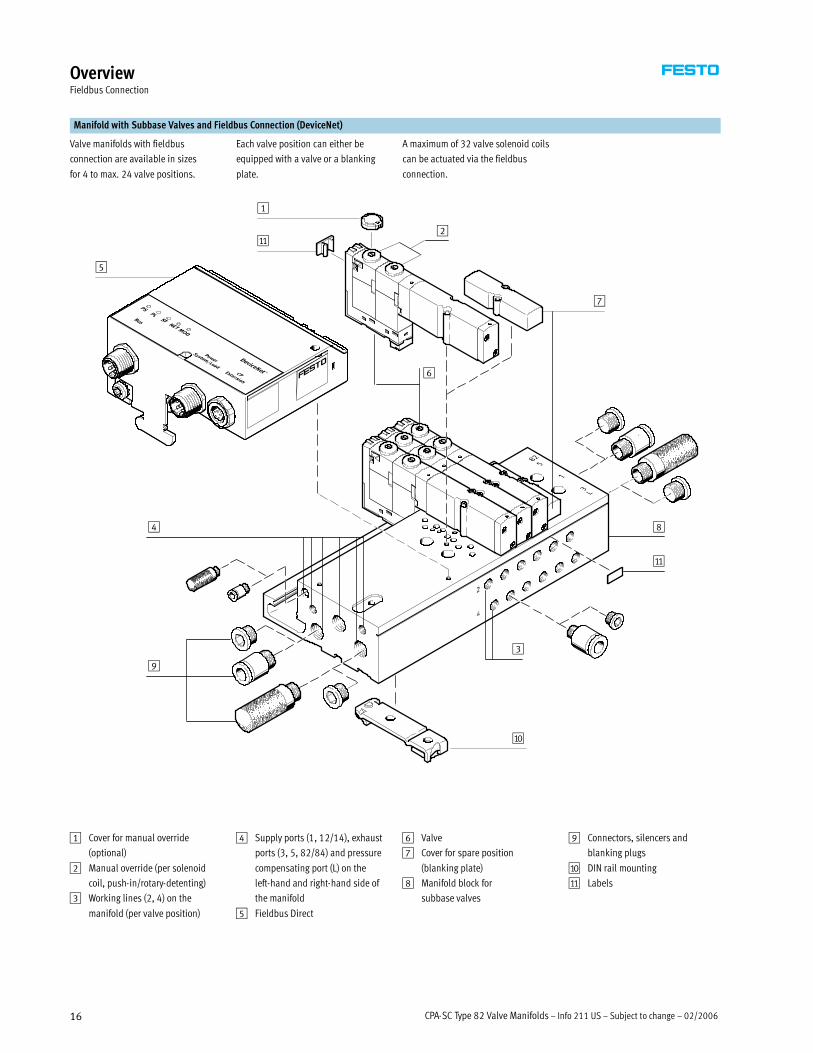
Manifold with Subbase Valves and Fieldbus Connection (DeviceNet)
Valve manifolds with fieldbus
connection are available in sizes
for 4 to max. 24 valve positions.
Each valve position can either be
equipped with a valve or a blanking
plate.
A maximum of 32 valve solenoid coils
can be actuated via the fieldbus
connection.
1
2
5
6
7
3
aA
9
aJ
8
aA
4
1 Cover for manual override
(optional)
2 Manual override (per solenoid
coil, push-in/rotary-detenting)
3 Working lines (2, 4) on the
manifold (per valve position)
4 Supply ports (1, 12/14), exhaust
ports (3, 5, 82/84) and pressure
compensating port (L) on the
left-hand and right-hand side of
the manifold
5 Fieldbus Direct
6 Valve
7 Cover for spare position
(blanking plate)
8 Manifold block for
subbase valves
9 Connectors, silencers and
blanking plugs
aJ DIN rail mounting
aA Labels

02/2006 – Subject to change – Info 211 US – CPA-SC Type 82 Valve Manifolds 17
OverviewFieldbus Connection
Manifold with Semi In-line Valves and Fieldbus Connection (DeviceNet)
Valve manifolds with fieldbus
connection are available in sizes
for 4 to max. 24 valve positions.
Each valve position can either be
equipped with a valve or a blanking
plate.
A maximum of 32 valve solenoid coils
can be actuated via the fieldbus
connection.
1
aJ
2
aB
5
6
7
3
aB
8
9
4
aA
1 Cover for manual override
(optional)
2 Manual override (per solenoid
coil, push-in/rotary-detenting)
3 Working lines (2, 4) on the valve
4 Supply ports (1, 12/14), exhaust
ports (3, 5, 82/84) and pressure
compensating port (L) on the
left-hand and right-hand side of
the manifold
5 Fieldbus Direct
6 Valve
7 Cover for vacant position
(blanking plate)
8 Manifold block for semi in-line
valves
9 Connectors, silencers and
blanking plugs
aJ Pneumatic connection plates for
semi in-line valves
aA DIN rail mounting
aB Labels

CPA-SC Type 82 Valve Manifolds – Info 211 US – Subject to change – 02/200618
Pneumatic ComponentsIndividual Valves
Valves
Subbase Valve
Subbase valves can be quickly
replaced since the pipe connection
remains on the manifold.
This design is also particularly flat.
Semi In-line Valve (With Working Ports on the Valve)
With semi in-line valves the
pneumatic connections are on the
top. This means that elbow connectors
are not needed.
There are subbase valves and semi
in-line valves with one solenoid coil
(single solenoid) or with two solenoid
coils (double solenoid) irrespective of
the valve function.
Blanking Plate
Plate without valve function for
reserving valve positions on a
valve manifold.
Blanking plates are attached to the
manifold block using two screws.

02/2006 – Subject to change – Info 211 US – CPA-SC Type 82 Valve Manifolds 19
Pneumatic ComponentsManifold Subbases and Single Subbases
Manifold Subbases Number of Valve Positions Connections
Order Code A – Working Lines (2, 4) on the Manifold Block
Manifold subbase for subbase valves
and blanking plates
2 … 20 �With working lines (2, 4),
M5 threaded hole
�With ports for supply air (1, 12/14)
and exhaust air (3, 5, 82/84)
�With pressure compensating port (L)
Single subbase for subbase valve 1
Order Code P – Working Lines (2, 4) on the Valve
Manifold subbase for semi in-line
valves and blanking plates
2 … 20 �No working lines
�With ports for supply air (1, 12/14)
and exhaust air (3, 5, 82/84)
�With pressure compensating port (L)
Single subbase for semi in-line valve 1
The compressed air supply and
exhaust air supply for the valve
manifold can either be on the
left-hand side or the right-hand side
of the valve manifold. Supply at both
sides is also possible. Ports that are
not required must be sealed with a
blanking plug.
An individual subbase is the ideal
solution in cramped space conditions.
All available valve types can be used
with an individual subbase.
Note
Semi in-line valves can also be
mounted on manifold blocks for
subbase valves. In this case the
corresponding working ports on the
manifold must be sealed using
blanking plugs.
CPA-SC Type 82 Valve Manifolds – Info 211 US – Subject to change – 02/200620
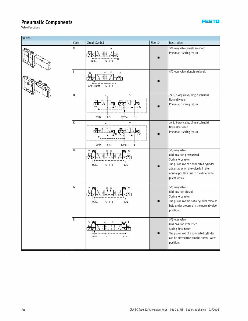
Pneumatic ComponentsValve Functions
Valves
Code Circuit Symbol Size 10 Description
M
�
5/2-way valve, single solenoid
Pneumatic spring return
J
�
5/2-way valve, double solenoid
N
�
2x 3/2-way valve, single solenoid
Normally open
Pneumatic spring return
K
�
2x 3/2-way valve, single solenoid
Normally closed
Pneumatic spring return
B
�
5/3-way valve
Mid-position pressurized
Spring force return
The piston rod of a connected cylinder
advances when the valve is in the
normal position due to the differential
piston areas.
G
�
5/3-way valve
Mid-position closed
Spring force return
The piston rod side of a cylinder remains
held under pressure in the normal valve
position.
E
�
5/3-way valve
Mid-position exhausted
Spring force return
The piston rod of a connected cylinder
can be moved freely in the normal valve
position.

02/2006 – Subject to change – Info 211 US – CPA-SC Type 82 Valve Manifolds 21
Pneumatic ComponentsValve Functions
Valves
Code Circuit Symbol Size 10 Description
X
�
1x 3/2-way valve
Normally closed, external compressed
air supply
Pneumatic spring return
Compressed air (–0.9 … +10 bar)
supplied at working port 4 can be
switched.
I
�
2x 2/2-way valve
Normally closed (operating pressure at
1 or 5), dual compressed air supply
(e.g. for vacuum switching with ejector
pulse)
Pneumatic spring return
� The vacuum is connected at port 5
� Port 14 switches the vacuum
� Port 12 switches the ejector pulse
� An external T connection must be
established between port 2, port 4,
and the vacuum generator
L
�
Blanking plate for spare position,
for valve manifold only.

CPA-SC Type 82 Valve Manifolds – Info 211 US – Subject to change – 02/200622
Pneumatic ComponentsAir Supply
Working Port
Code Description
B M5 threaded connection
E QS-3 push-in fitting, 3 mm tubing connection
F QS-4 push-in fitting, 4 mm tubing connection
Pneumatic Connection
Supply and Exhaust
The valves are supplied with
compressed air via various valve
manifold blocks or single subbases.
These contain common lines for
compressed air supply, exhausting
and pilot exhausts from all valves.
The common lines on a CPA-SC valve
manifold can be connected
� At the left (code L)
� At the right (code R) or
� At both ends (code B)
Pilot Air
The CPA-SC valve manifold is suitable
for internal or external pilot air.
See Graphs� Page 37
Internal Pilot Air
If the supply pressure for your
CPA-SC valve manifold is between
3 and 8 bar, it can be operated with
internally distributed pilot air. Pilot
air is branched at the left-hand end
plate of port 1 for this purpose.
External Pilot Air
If the supply pressure for your
CPA-SC valve manifold is between
-0.9 and +10 bar, it must be operated
with external pilot air. The pilot air is
supplied via port 12/14 in this case.

02/2006 – Subject to change – Info 211 US – CPA-SC Type 82 Valve Manifolds 23
Pneumatic ComponentsAir Supply
Pneumatic Supply
With Manifold Block Code Connection Ports for Supply and Exhaust
Code H
Metric QS Connection
For 8 mm Tubing
Code D
Gx Threaded
Connection
Designation Type Type
Compressed Air Supplied by Means of Internal Pilot Air, Exhausting via Silencer
S 1 Compressed air/vacuum supply Push-in fitting QS-Gx-8-I –
3/5 Exhaust Silencer UC-x –
12/14 Pilot air – – –
82/84 Exhaust for pilot air Silencer UC-M5 –
L Pressure compensation Silencer UC-M5 –
Compressed Air Supplied via External Pilot Air, Exhausting via Silencer
T 1 Compressed air/vacuum supply Push-in fitting QS-Gx-8-I –
3/5 Exhaust Silencer UC-x –
12/14 Pilot air Push-in fitting QSM-M5-4-I –
82/84 Exhaust for pilot air Silencer UC-M5 –
L Pressure compensation Silencer UC-M5 –
Compressed Air Supplied by Means of Internal Pilot Air, Ducted Exhaust
V 1 Compressed air/vacuum supply Push-in fitting QS-Gx-8-I –
3/5 Exhaust Push-in fitting QS-Gx-8-I –
12/14 Pilot air – – –
82/84 Exhaust for pilot air Push-in fitting QSM-M5-4-I –
L Pressure compensation Silencer UC-M5 –
Compressed Air Supplied via External Pilot Air, Ducted Exhaust
X 1 Compressed air/vacuum supply Push-in fitting QS-Gx-8-I –
3/5 Exhaust Push-in fitting QS-Gx-8-I –
12/14 Pilot air Push-in fitting QSM-M5-4-I –
82/84 Exhaust for pilot air Push-in fitting QSM-M5-4-I –
L Pressure compensation Silencer UC-M5 –

CPA-SC Type 82 Valve Manifolds – Info 211 US – Subject to change – 02/200624
Pneumatic ComponentsAir Supply
Pneumatic Supply
With Single Subbase Code Connection Ports for Supply and Exhaustg
Code B
M5 Threaded Connection
Code F
Metric Push-in Fitting QS4
For 4 mm Tubing
Designation Type Type
Compressed Air Supplied by Means of Internal Pilot Air, Exhausting via Silencer
S 1 Compressed air/vacuum supply Push-in fitting – QSM-M5-4-I
3/5 Exhaust Silencer – UC-M5
12/14 Pilot air – – –
82/84 Exhaust for pilot air Silencer – U-M3
L Pressure compensation Silencer – U-M3
Compressed Air Supplied via External Pilot Air, Exhausting via Silencer
T 1 Compressed air/vacuum supply Push-in fitting – QSM-M5-4-I
3/5 Exhaust Silencer – UC-M5
12/14 Pilot air Push-in fitting – QSM-M3-3-I
82/84 Exhaust for pilot air Silencer – U-M3
L Pressure compensation Silencer – U-M3
Compressed Air Supplied by Means of Internal Pilot Air, Ducted Exhaust
V 1 Compressed air/vacuum supply Push-in fitting – QSM-M5-4-I
3/5 Exhaust Push-in fitting – QSM-M5-4-I
12/14 Pilot air – – –
82/84 Exhaust for pilot air Push-in fitting – QSM-M3-3-I
L Pressure compensation Silencer – U-M3
Compressed Air Supplied via External Pilot Air, Ducted Exhaust
X 1 Compressed air/vacuum supply Push-in fitting – QSM-M5-4-I
3/5 Exhaust Push-in fitting – QSM-M5-4-I
12/14 Pilot air Push-in fitting – QSM-M3-3-I
82/84 Exhaust for pilot air Push-in fitting – QSM-M3-3-I
L Pressure compensation Silencer – U-M3
Note
Port L compensates the pressure
between moving parts inside the
valve and the surrounding
environment.
A silencer protects against
contamination.
Port L must not be sealed by
blanking plugs at both ends.
02/2006 – Subject to change – Info 211 US – CPA-SC Type 82 Valve Manifolds 25
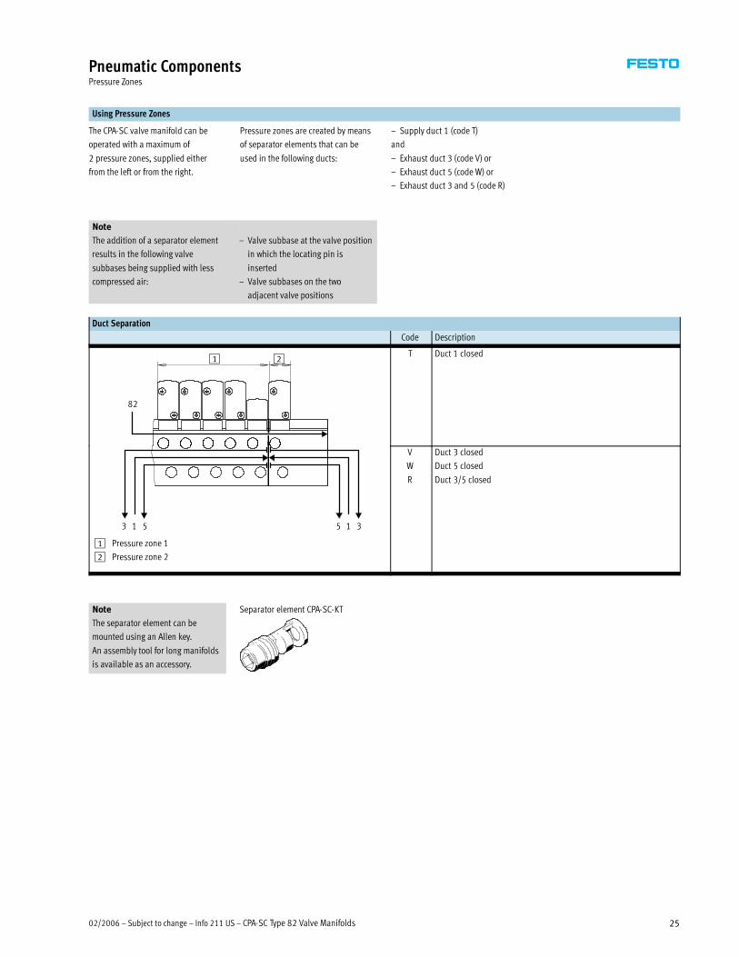
Pneumatic ComponentsPressure Zones
Using Pressure Zones
The CPA-SC valve manifold can be
operated with a maximum of
2 pressure zones, supplied either
from the left or from the right.
Pressure zones are created by means
of separator elements that can be
used in the following ducts:
– Supply duct 1 (code T)
and
– Exhaust duct 3 (code V) or
– Exhaust duct 5 (code W) or
– Exhaust duct 3 and 5 (code R)
Note
The addition of a separator element
results in the following valve
subbases being supplied with less
compressed air:
– Valve subbase at the valve position
in which the locating pin is
inserted
– Valve subbases on the two
adjacent valve positions
Duct Separation
Code Description
82
1 2T Duct 1 closed
1 53 1 35
1 Pressure zone 1
2 Pressure zone 2
V
W
R
Duct 3 closed
Duct 5 closed
Duct 3/5 closed
Note Separator element CPA-SC-KT
The separator element can be
mounted using an Allen key.
An assembly tool for long manifolds
is available as an accessory.

CPA-SC Type 82 Valve Manifolds – Info 211 US – Subject to change – 02/200626
Electrical ComponentsIndividual Electrical Connections
Electrical Power as a Result of Current Reduction
Each valve solenoid coil is protected
with a spark arresting protective
circuit as well as against polarity
reversal.
All valve types are additionally
equipped with integrated current
reduction.Power management
Individual Electrical Connection
With an individual electrical
connection, the plug is connected
directly to the valve.
Two individual electrical connection
types are available for the valve
manifold and for a single subbase:
�Horizontal connection (HC) or
� Plug-in (PI)
Note
Connecting cables with 2- or 3-wires
are available for single solenoid
valves with one solenoid coil or
double solenoid valves with two
solenoid coils.
Individual Electrical Connection – Horizontal Connection (HC)
Valves on Manifold Block
Order Code IH
Valve on Single Subbase
Order Code SH
The valve manifold can be configured
with 2 to 16 valve positions. This
means that 32 valve solenoid coils
can be actuated with this type of
electrical connection.
The horizontal connection (HC) must
be removed when replacing the valve.
With a single subbase, the electrical
connection can be plugged directly
into the valve.
Dimensions – Horizontal Connection (HC) Download CAD data� www.festo.com/en/engineering
Type Code L1 Number of Valve Cable Color
Cable Length
[m]
Solenoid Coils Pin 1
Common
Pin 2
Solenoid Coil 12
Pin 3
Solenoid Coil 14
KMH-0.5 CH 0.5 1 coil black – red
KMH-1 CI 1 1 coil black – red
KMH-2.5 CJ 2.5 1 coil black – red
KMH-5 CK 5 1 coil black – red
KMH-D-0.5 CD 0.5 2 coils black blue red
KMH-D-1 CE 1 2 coils black blue red
KMH-D-2.5 CF 2.5 2 coils black blue red
KMH-D-5 CG 5 2 coils black blue red

02/2006 – Subject to change – Info 211 US – CPA-SC Type 82 Valve Manifolds 27
Electrical ComponentsIndividual Electrical Connections
Individual Electrical Connection – Plug-in (PI)
Valves on Manifold Block
Codes IP, IQ
Valve on Single Subbase
Codes SP, SQ
The valve manifold can be configured
with 2 to 16 valve positions. This
means that 32 valve solenoid coils
can be actuated with this type of
electrical connection.
The connector plug is inserted into
the slot on the manifold block.
To replace a valve or extend the
manifold (vacant position), all you
need do is loosen two screws; the
connector plug remains in the slot.
With this electrical connection, the
connector plug is mounted on an
adapter. This adapter is then attached
to the single subbase.
Dimensions – Plug-in Connection (PI) Download CAD data� www.festo.com/en/engineering
Type Code L1 Number of Valve Cable Color
Cable Length
[m]
Solenoid Coils Pin 1
Common
Pin 2
Solenoid Coil 12
Pin 3
Solenoid Coil 14
MHAP-PI – 0.5 1 coil black – red
MHAP-PI-1 – 1 1 coil black – red
MHAP-PI-D-0.5 – 0.5 2 coils black blue red
MHAP-PI-D-1 – 1 2 coils black blue red

CPA-SC Type 82 Valve Manifolds – Info 211 US – Subject to change – 02/200628
Electrical ComponentsMultipin Connection
Electrical Multipin Plug Connection
The following multipin plug
connection types are offered for
the CPA-SC valve manifold:
� Sub-D multipin plug connection
(25-pin)
�Multipin plug connection with
connector for flat cable (26-pin)
Pins 1 … 20 are used for coils 1 … 20
in sequence. If there are fewer than
20 coils on the valve manifold, the
remaining pins up to 20 remain free.
Pins 21 and upwards are reserved for
earthed conductors. Four solenoid
coils are always combined on an
earthed conductor.
This allows individual valve groups to
be disconnected separately or a
combination of NPN- and
PNP-switching valves to be achieved.
Each pin on the multipin plug can
activate just one valve solenoid coil.
For a maximum configurable number
of 20 valve positions, 20 valves each
with a single solenoid coil can be
addressed.
With 10 or less valve positions,
2 valve solenoid coils can be
addressed per valve. Where there are
more than 12 valve positions, the
number of available valve positions
for valves with two solenoid coils is
reduced (� See table below).
Example:
With 16 valve positions, valves with
one or two solenoid coils can be
actuated on the first four (0 … 3)
positions. Valves with only one
solenoid coil are permitted at
positions 4 … 15.
Address/ Number of the Valve Position/
Solenoid Coil 0 1 2 3 4 5 6 7 8 9 10 11 12 13 14 15 16 17 18 19
20 1 1 1 1 1 1 1 1 1 1 1 1 1 1 1 1 1 1 1 1
20 2 2 2 2 1 1 1 1 1 1 1 1 1 1 1 1
20 2 2 2 2 2 2 2 2 1 1 1 1
20 2 2 2 2 2 2 2 2 2 2
16 2 2 2 2 2 2 2 2
12 2 2 2 2 2 2
8 2 2 2 2
Electrical Multipin Plug Connection – Sub-D
Order Code: MS
With this electrical connection option,
all valves are actuated centrally via the
25-pin plug connector.
The electrical connection is located on the
left-hand side and can be turned 90°.

02/2006 – Subject to change – Info 211 US – CPA-SC Type 82 Valve Manifolds 29
Electrical ComponentsPin Allocation, Sub-D 25-pin Cable
Pin Allocation – Connector for Sub-D, 25-pin Cable
Pin Address/ Core Color2) Valve Positions1)/
Solenoid KMP6-25P-12 KMP6-25P-25 2 4 6 8 10 12 16 20
Coil Valve Position No./Coil Designation
1 0 White White 0/14 0/14 0/14 0/14 0/14 0/14 0/14 0/14
2 1 Brown Brown 0/12 0/12 0/12 0/12 0/12 0/12 0/12 1/14
3 2 Green Green 1/14 1/14 1/14 1/14 1/14 1/14 1/14 2/14
4 3 Yellow Yellow 1/12 1/12 1/12 1/12 1/12 1/12 1/12 3/14
5 4 Gray Gray 2/14 2/14 2/14 2/14 2/14 2/14 4/14
6 5 Pink Pink 2/12 2/12 2/12 2/12 2/12 2/12 5/14
7 6 Blue Blue 3/14 3/14 3/14 3/14 3/14 3/14 6/14
8 7 Red Red 3/12 3/12 3/12 3/12 3/12 3/12 7/14
9 8 Black Black 4/14 4/14 4/14 4/14 4/14 8/14
10 9 Purple Purple 4/12 4/12 4/12 4/12 5/14 9/14
11 10 Gray-pink Gray-pink 5/14 5/14 5/14 5/14 6/14 10/14
12 11 Red-blue Red-blue 5/12 5/12 5/12 5/12 7/14 11/14
13 12 – White-green 6/14 6/14 6/14 8/14 12/14
14 13 – Brown-green 6/12 6/12 6/12 9/14 13/14
15 14 – White-yellow 7/14 7/14 7/14 10/14 14/14
16 15 – Yellow-brown 7/12 7/12 7/12 11/14 15/14
17 16 – White-green 8/14 8/14 12/14 16/14
18 17 – Brown-green 8/12 9/14 13/14 17/14
19 18 – White-yellow 9/14 10/14 14/14 18/14
20 19 – Yellow-brown 9/12 11/14 15/14 19/14
21 com – White-blue Coil 16 … 19
22 com – Brown-blue Coil 12 … 15
23 com White-green White-red Coil 8 … 11
24 com Brown-green Brown-red Coil 4 … 7
25 com White-yellow White-black Coil 0 … 3
No. of Solenoid Coils 4 8 12 16 20 20 20 20
1) Gray boxes indicate double solenoid valve assignments.
2) As per IEC 757
Dimensions – Sub-D Plug with Cable Download CAD data� www.festo.com/en/engineering
1 25-pin plug
Type Code B1
[mm]
D1
[mm]
H1
[mm]
L1
[mm]
L2
[m]
KMP6-25P-20-2.5 CP 16 10.3 53.4 37.7 2.5
KMP6-25P-20-5 CQ 16 10.3 53.4 37.7 5
KMP6-25P-20-10 CR 16 10.3 53.4 37.7 10
KMP6-25P-12-2.5 CV 16 8.5 53.4 37.7 2.5
KMP6-25P-12-5 CW 16 8.5 53.4 37.7 5
KMP6-25P-12-10 CX 16 8.5 53.4 37.7 10
CPA-SC Type 82 Valve Manifolds – Info 211 US – Subject to change – 02/200630
Electrical ComponentsPin Allocation, Flat Cable
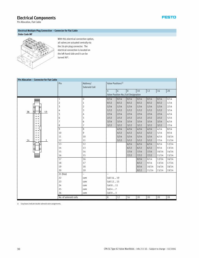
Electrical Multipin Plug Connection – Connector for Flat Cable
Order Code MF
With this electrical connection option,
all valves are actuated centrally via
the 26-pin plug connector. The
electrical connection is located on
the left-hand side and it can be
turned 90°.
Pin Allocation – Connector for Flat Cable
Pin Address/
Solenoid Coil
Valve Positions1)
4 6 8 10 12 16 20
Valve Position No./Coil Designation
1 0 0/14 0/14 0/14 0/14 0/14 0/14 0/14
2 1 0/12 0/12 0/12 0/12 0/12 0/12 1/14
3 2 1/14 1/14 1/14 1/14 1/14 1/14 2/14
13264 3 1/12 1/12 1/12 1/12 1/12 1/12 3/14
13265 4 2/14 2/14 2/14 2/14 2/14 2/14 4/14
6 5 2/12 2/12 2/12 2/12 2/12 2/12 5/14
7 6 3/14 3/14 3/14 3/14 3/14 3/14 6/14
8 7 3/12 3/12 3/12 3/12 3/12 3/12 7/14
9 8 4/14 4/14 4/14 4/14 4/14 8/14
10 9 4/12 4/12 4/12 4/12 5/14 9/14
11 10 5/14 5/14 5/14 5/14 6/14 10/14
114 12 11 5/12 5/12 5/12 5/12 7/14 11/14
13 12 6/14 6/14 6/14 8/14 12/14
14 13 6/12 6/12 6/12 9/14 13/14
15 14 7/14 7/14 7/14 10/14 14/14
16 15 7/12 7/12 7/12 11/14 15/14
17 16 8/14 8/14 12/14 16/14
18 17 8/12 9/14 13/14 17/14
19 18 9/14 10/14 14/14 18/14
20 19 9/12 11/14 15/14 19/14
21 (free) – –
22 com Coil 16 … 19
23 com Coil 12 … 15
24 com Coil 8 … 11
25 com Coil 4 … 7
26 com Coil 0 … 3
No. of solenoid coils 8 12 16 20 20 20 20
1) Gray boxes indicate double solenoid valve assignments.

02/2006 – Subject to change – Info 211 US – CPA-SC Type 82 Valve Manifolds 31
Electrical ComponentsFieldbus Connection
Fieldbus Direct (DeviceNet)
Fieldbus Direct is a system for the
compact connection of a valve
manifold of various size to different
fieldbus standards.
The CP string extension option allows
the functions and components of the
CP installation system to be used.
The I/O modules and cables for the
CP string extension are ordered using
the order code for the CP installation
system.
� See CP Valve Installation System
Product Guide (Info 221)
Address Allocation – Solenoid Coils
1
2
3 4 1 Valve solenoid 12
2 Valve solenoid 14
3 LED valve solenoid 12
4 LED valve solenoid 14
The addresses of the valve solenoids
on the CPA-SC-DN are allocated from
left to right, while the addresses of
the individual valve positions are
allocated from front to back.
Example:
Valve manifold where the first
8 valve positions are prepared for
2 solenoids each.
Each valve position can actuate one or
two solenoid coils depending on the
configuration (number of valve
positions and internal wiring). It then
occupies one or two addresses. The
internal wiring cannot be changed.
The number of addresses each valve
position occupies has nothing to do
with what is actually mounted on the
valve position (valve, blanking plate).
If a valve position for 2 addresses is
actually equipped with two solenoid
coils, the following allocation applies:
� Valve solenoid 14 occupies the less
significant address
� Valve solenoid 12 occupies the
more significant address
If a valve position for 2 addresses is
equipped with only one solenoid coil,
the more significant address remains
unused. The valve position occupies
two addresses nonetheless.
Address/ Number of the Valve Position/
Solenoid Coil 0 1 2 3 4 5 6 7 8 9 10 11 12 13 14 15 16 17 18 19 20 21 22 23
32 2 2 2 2 2 2 2 2 1 1 1 1 1 1 1 1 1 1 1 1 1 1 1 1
32 2 2 2 2 2 2 2 2 2 2 2 2 1 1 1 1 1 1 1 1 – – – –
32 2 2 2 2 2 2 2 2 2 2 2 2 2 2 2 2 – – – – – – – –
24 2 2 2 2 2 2 2 2 2 2 2 2 – – – – – – – – – – – –
20 2 2 2 2 2 2 2 2 2 2 – – – – – – – – – – – – – –
16 2 2 2 2 2 2 2 2 – – – – – – – – – – – – – – – –
12 2 2 2 2 2 2 – – – – – – – – – – – – – – – – – –
8 2 2 2 2 – – – – – – – – – – – – – – – – – – – –

CPA-SC Type 82 Valve Manifolds – Info 211 US – Subject to change – 02/200632
Installation and OperationValves
Valves
Valve Replacement
The valves are attached to the metal
manifold block using two screws.
This means that they can be easily
replaced.
Extension
Spare positions can be replaced by
valves at a later date. The dimensions,
mounting points and existing
pneumatic installations remain
unchanged by this. Valve codes
(M, J, N, K, B, G, E, X, I) are located
on the front of the valves beneath
the manual override.
Note
Plug-in Versions
If a spare position is replaced by a
valve, a plug-in socket must also be
ordered and inserted into the slot.
When ordering an HC manifold, you
must determine the number and
length of connecting cable you need
and specify them in the order code.
Multipin Plug and Individual Valve Connection
Each valve solenoid coil is allocated
an LED which indicates its operating
status. Labels (type IBS-6x10) can be
applied to each valve for labeling
purposes. Alternatively labels (type
MH-BZ-80x) can also be affixed to the
slot on the manifold block.
The manual override (MO) allows
the valve to be switched when in
the electrically non-activated or
de-energized status. The valve is
switched by pushing the manual
override. The set switching status
can also be secured by rotating the
manual override.
A cover can be fitted over the manual
override to prevent it from being
actuated accidentally (code V).
Note
A manually actuated valve
(manual override) cannot be
reset electrically. Conversely,
an electrically actuated valve
cannot be reset using the
mechanical manual override.
1
2
3
4
5
1 Cover for manual override (code
V or accessory CPA-SC-MO-V)
2 Optional manual override
(pushing and detenting by
turning with a screwdriver)
3 Slot for labels type MH-BZ-80x
4 Location for valve label
type ISB-6x10
5 LED signal status display per
solenoid coil
02/2006 – Subject to change – Info 211 US – CPA-SC Type 82 Valve Manifolds 33
Installation and OperationManual Override
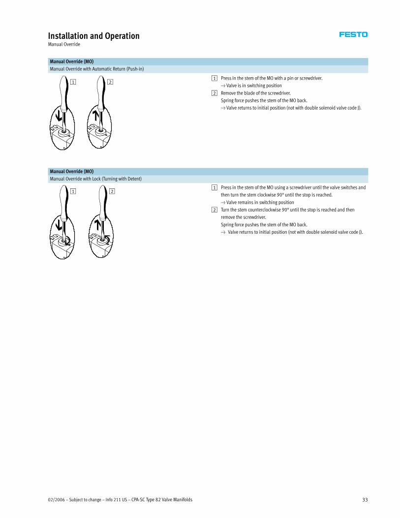
Manual Override (MO)
Manual Override with Automatic Return (Push-in)
1 21 Press in the stem of the MO with a pin or screwdriver.
> Valve is in switching position
2 Remove the blade of the screwdriver.
Spring force pushes the stem of the MO back.
> Valve returns to initial position (not with double solenoid valve code J).
Manual Override (MO)
Manual Override with Lock (Turning with Detent)
1 21 Press in the stem of the MO using a screwdriver until the valve switches and
then turn the stem clockwise 90° until the stop is reached.
> Valve remains in switching position
2 Turn the stem counterclockwise 90° until the stop is reached and then
remove the screwdriver.
Spring force pushes the stem of the MO back.
> Valve returns to initial position (not with double solenoid valve code J).
CPA-SC Type 82 Valve Manifolds – Info 211 US – Subject to change – 02/200634
Installation and OperationMounting
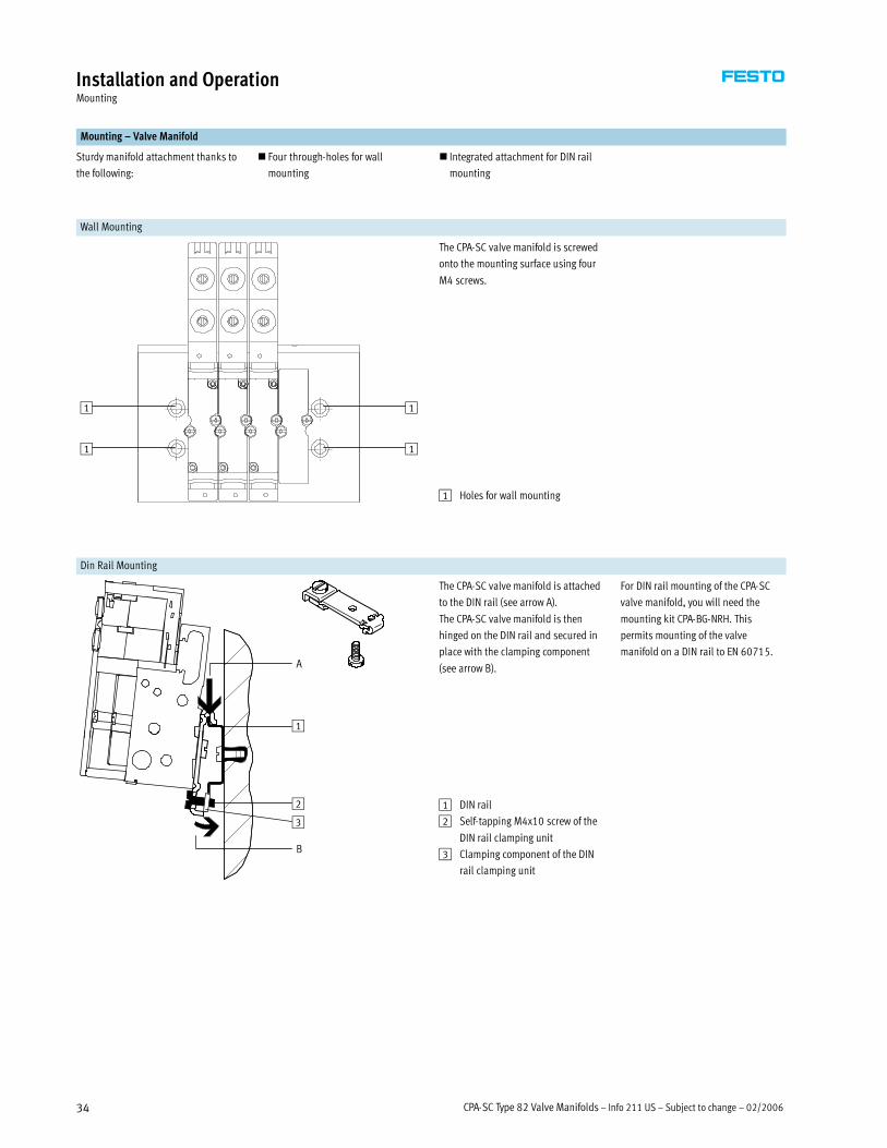
Mounting – Valve Manifold
Sturdy manifold attachment thanks to
the following:
� Four through-holes for wall
mounting
� Integrated attachment for DIN rail
mounting
Wall Mounting
The CPA-SC valve manifold is screwed
onto the mounting surface using four
M4 screws.
1
1
1
1
1 Holes for wall mounting
Din Rail Mounting
A
1
The CPA-SC valve manifold is attached
to the DIN rail (see arrow A).
The CPA-SC valve manifold is then
hinged on the DIN rail and secured in
place with the clamping component
(see arrow B).
For DIN rail mounting of the CPA-SC
valve manifold, you will need the
mounting kit CPA-BG-NRH. This
permits mounting of the valve
manifold on a DIN rail to EN 60715.
B
2
3
1 DIN rail
2 Self-tapping M4x10 screw of the
DIN rail clamping unit
3 Clamping component of the DIN
rail clamping unit
02/2006 – Subject to change – Info 211 US – CPA-SC Type 82 Valve Manifolds 35
Installation and OperationMounting
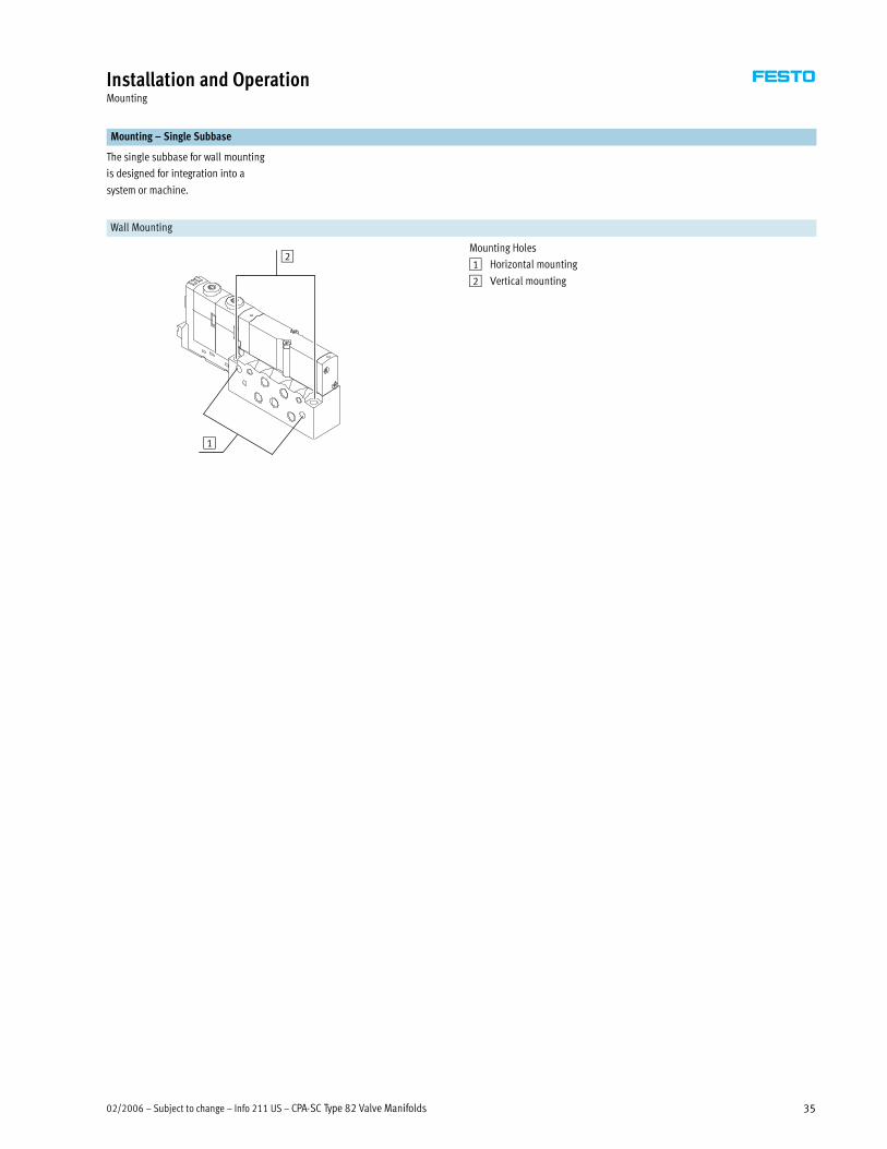
Mounting – Single Subbase
The single subbase for wall mounting
is designed for integration into a
system or machine.
Wall Mounting
1
2Mounting Holes
1 Horizontal mounting
2 Vertical mounting

CPA-SC Type 82 Valve Manifolds – Info 211 US – Subject to change – 02/200636
Technical DataPneumatic
Flow Rate: 150 l/min
Width: 10 mm
Voltage: 24 V DC
General Technical Data
Valve 5/2-way Valve 2x 3/2-way Valve 5/3-way Valve 1x
3/2-way
Valve
2x
2/2-way
Valve
Normally Mid-position Normally
Single
Solenoid
Double
Solenoid
Open Closed Pressurized Closed Exhausted Closed Closed
Valve Function Ordering Code M J N K B G E X I
Design Electromagnetically actuated piston spool valve
Width [mm] 10
Nominal diameter [mm] 2.5
Lubrication Lubricated for life, PWIS-free (free of paint-wetting impairment substances)
Type of mounting Wall mountingyp g
On DIN rail to EN 60715
Assembly position Any
Manual override Pushing/detented by turning
Pneumatic Connections
Pneumatic connection Via manifold block, PRS manifold or individual connection
Supply port 1 Gx (M5 with individual block)
Exhaust port 3/5 Gx (M5 with individual block)
Working lines 2/4 Depending on the connection type selected
Metric
�M5
�QS-3
�QS-4
Inch
�QS-1/8
�QS-5/32
Pilot air port 12/14 M5 (M3 with individual block)
Pilot exhaust air port 82/84 M5 (M3 with individual block)
Pressure compensating port L M5, M3

02/2006 – Subject to change – Info 211 US – CPA-SC Type 82 Valve Manifolds 37
Technical DataPneumatic
Operating Pressure [bar]
Valve Function Ordering Code M J N K B G E X I
With internal pilot air supply +3 … +8
With external pilot air supply –0.9 … +10 +3 … +10 –0.9 … +10 +3 … +10
Pilot Pressure p2 as a Function of Working Pressure p1 with External Pilot Air Supply
For Valve Subbases with Code M, J, B, G, E, X
p2[bar]
p1 [bar]1 Operating range for valves with
external pilot air supply
For Valve Subbases with Code N, K, I
p1 [bar]
p2[bar]
1 Operating range for valves with
external pilot air supply

CPA-SC Type 82 Valve Manifolds – Info 211 US – Subject to change – 02/200638
Technical DataPneumatic
Valve Response Times [ms]
Valve Function Ordering Code M J N K B G E X I
Response times On 10 – 10 10 10 10 10 10 10p
Off 20 – 20 20 25 25 25 20 20
Changeover – 10 – – – – – – –
Operating and Environmental Conditions
Valve Function Ordering Code M J N K B G E X I
Operating medium Filtered compressed air, lubricated or unlubricated, inert gases
Grade of filtration [µm] 40
Ambient temperature [°C] –5 … +60 –5 … +402) –5 … +60 –5 … +402)
Ambient temperature with
DeviceNet connection
[°C] –5 … +50 –5 … +402) –5 … +50 –5 … +402)
Storage temperature [°C] –20 … +40
Corrosion resistance class CRC1) 1
1) Corrosion resistance class 1 according to Festo standard 940070. Components requiring low corrosion resistance. Transport and storage protection. Parts that do not have primarily decorative surface requirements, e.g.
in internal areas that are not visible or behind covers.
2) Restricted ambient temperature in case of two permanently activated solenoid coils per valve location, otherwise same temperature range as ordering code M.
Restricted ambient temperature in case of fieldbus connection, otherwise same temperature range as ordering code M.
Materials
Valve Function Ordering Code M J N K B G E X I
Manifold block Wrought aluminum alloy
Valve subbase Die-cast aluminum
Seal Nitrile rubber
Product Weight [g] Approx. Weights
Valve Function Ordering Code M J N K B G E X I
Basic manifold block weight 125
Additional manifold block weight per
valve position
40
Single subbase 45
Per valve subbase 40
Fieldbus connection 150

02/2006 – Subject to change – Info 211 US – CPA-SC Type 82 Valve Manifolds 39
Technical DataPneumatic
Standard Nominal Flow Rate [l/min]
Code Valve Function Valve Single Subbase CPA-SC Valve
Manifold with
Multipin Plug
Connection/
Individual PI
Connections
CPA-SC Valve
Manifold with
Individual Horizontal
Connections
Subbase Valve
M 5/2-way valve,
single solenoid
220 170 150 120
J 5/2-way valve,
double solenoid
220 170 150 120
N 2x 3/2-way valve,
normally open
220 170 150 120
K 2x 3/2-way valve,
normally closed
180 150 120 120
B 5/3-way valve,
mid-position pressurized
220 150 120 120
G 5/3-way valve,
mid-position closed
180 150 120 120
E 5/3-way valve,
mid-position exhausted
180 150 120 120
X 1x 3/2-way valve 120 – 100 85
I 2x 2/2-way valve 150 140 140 120
Semi In-line Valve with Working Port M5
M 5/2-way valve,
single solenoid
200 180 180 180
J 5/2-way valve,
double solenoid
200 180 180 180
N 2x 3/2-way valve,
normally open
200 180 180 180
K 2x 3/2-way valve,
normally closed
150 150 150 150
B 5/3-way valve,
mid-position pressurized
180 180 180 180
G 5/3-way valve,
mid-position closed
150 150 150 150
E 5/3-way valve,
mid-position exhausted
180 170 180 170
X 1x 3/2-way valve 120 – 120 120
I 2x 2/2-way valve 150 150 150 150

CPA-SC Type 82 Valve Manifolds – Info 211 US – Subject to change – 02/200640
Technical DataPneumatic
Standard Nominal Flow Rate [l/min]
Code Valve Function Valve Single Subbase CPA-SC Valve
Manifold with
Multi-pin Plug
Connection/
Individual PI
Connections
CPA-SC Valve
Manifold with
Individual Horizontal
Connections
Semi in-Line Valve, Working Port with QS-3 Fitting (for 3 mm tubing)
M 5/2-way valve,
single solenoid
140 140 140 140
J 5/2-way valve,
double solenoid
140 140 140 140
N 2x 3/2-way valve,
normally open
140 140 140 140
K 2x 3/2-way valve,
normally closed
130 130 130 130
B 5/3-way valve,
mid-position pressurized
140 140 140 140
G 5/3-way valve,
mid-position closed
130 130 130 130
E 5/3-way valve,
mid-position exhausted
140 140 140 140
X 1x 3/2-way valve 100 – 100 100
I 2x 2/2-way valve 130 130 130 130
Semi In-line Valve, Working Port with QS-4 Fitting (for 4 mm tubing)
M 5/2-way valve,
single solenoid
180 170 180 180
J 5/2-way valve,
double solenoid
180 170 180 180
N 2x 3/2-way valve,
normally open
180 170 180 180
K 2x 3/2-way valve,
normally closed
150 150 150 150
B 5/3-way valve,
mid-position pressurized
180 170 180 170
G 5/3-way valve,
mid-position closed
150 150 150 150
E 5/3-way valve,
mid-position exhausted
170 170 170 170
X 1x 3/2-way valve 120 – 120 120
I 2x 2/2-way valve 150 140 150 150

02/2006 – Subject to change – Info 211 US – CPA-SC Type 82 Valve Manifolds 41
Technical DataElectrical
Electrical Data
Valve Function Ordering Code M J N K B G E X I
Electromagnetic compatibility of the
CPA-SC valve terminal (Sub-D or flat
Interference emission tested to EN 61000-6-4, industry
CPA-SC valve terminal (Sub-D or flat
cable connection)Interference immunity1) tested to EN 61000-6-2, industry
Protection against electric shock
(protection against direct and indirect
contact to EN 60204-1/IEC 204)
By means of PELV power supply unit
Operating Voltage of Valves and Electronic Components
Nominal operating voltage [V] 24 DC
Operating voltage range [V] 20.4 … 26.4 DC
Electrical Power Consumption
Electronic components [mA] 200 and current consumption of sensors
Valves [W] Pull: 1, hold: 0.3
Residual ripple [Vss] 4
Cut-off pause [ms] Min. 10
Switching frequency [Hz] Max. 10
Duty cycle 100% at 40°C ambient temperature
Protection class to EN 60529 IP40 (in assembled state and with detented plug)
Relative air humidity 90% at 40°C, non-condensing
Vibration resistance To DIN/IEC 68/EN 60068, Parts 2-6, severity level 2
Continuous shock resistance To DIN/IEC 68/EN 60068, Parts 2-27, severity level 2
1) The maximum signal line length is 10 m.

CPA-SC Type 82 Valve Manifolds – Info 211 US – Subject to change – 02/200642
Technical DataDimensions
Subbase Valve Download CAD data� www.festo.com/en/engineering
With Individual Plug-in Connection (PI) With Individual Horizontal Connection (HC)
1 Individual plug-in connection
2 Manual override (MO)
3 Manual override cover
1 Individual horizontal connection
2 Manual override (MO)
3 Manual override cover
Semi In-line Valve with M5 Working Port Download CAD data� www.festo.com/en/engineering
With Individual Plug-in Connection (PI) With Individual Horizontal Connection (HC)
1 Individual plug-in connection 1 Individual horizontal connection
Semi In-line Valve with QS-3/QS-4 Working Port Download CAD data� www.festo.com/en/engineering
With Individual Plug-in Connection (PI) With Individual Horizontal Connection (HC)
1 Individual plug-in connection 1 Individual horizontal connection

02/2006 – Subject to change – Info 211 US – CPA-SC Type 82 Valve Manifolds 43
Technical DataDimensions
Single Subbase Download CAD data� www.festo.com/en/engineering
With Individual Plug-in Connection (PI)
1 Semi in-line valve with
M5 threaded connections
5 Push-in fitting
6 Working lines for subbase
valve (not required with semi
in-line valves)
9 4x mounting holes
aJ Silencer for exhaust air
Valve Type L3 [mm]
Semi in-line valve with working port M5 50.8
with working port QS-3 [for 3 mm tubing] 57.2
with working port QS-4 [for 4 mm tubing] 57.2
with working port QS-1/8 [for 1/8� tubing] 63.7
with working port QS-5/32 [for 5/32� tubing] 63.5
Subbase valve 48.3
Blanking plate 37.1

CPA-SC Type 82 Valve Manifolds – Info 211 US – Subject to change – 02/200644
Technical DataDimensions
Single Subbase Download CAD data� www.festo.com/en/engineering
With Individual Horizontal Connection (HC)
1 Semi in-line valve with
M5 threaded connection
5 Push-in fitting
6 Working lines for subbase
valve (not required with semi
in-line valves)
9 4x mounting holes
aJ Silencer for exhaust air
Valve Type L3 [mm]
Semi in-line valve with working port M5 43.9
with working port QS-3 [for 3 mm tubing] 50.3
with working port QS-4 [for 4 mm tubing] 50.3
with working port QS-1/8 [for 1/8� tubing] 63.7
with working port QS-5/32 [for 5/32� tubing] 63.5
Subbase valve 41.4
Blanking plate 30.2

02/2006 – Subject to change – Info 211 US – CPA-SC Type 82 Valve Manifolds 45
Technical DataDimensions
Valve Manifold Download CAD data� www.festo.com/en/engineering
With Sub-D Multipin Plug Connection
1 Semi in-line valve with
M5 threaded connection
2 Semi in-line valve with
integrated push-in fitting
3 Subbase valve
4 Blanking plate for
spare position
5 Push-in fitting
6 Working lines for subbase
valves (not required with semi
in-line valves)
7 Mounting for DIN rail
TH 35-7.5 EN60715
8 DIN rail
9 4x mounting holes
aA Sub-D multi-pin plug
connection, 25-pin,
rotatable 90°
Valve Positions L1 [mm] L2 [mm]
4 102 75
6 123 96
8 144 117
10 165 138
12 186 159
16 228 201
20 270 243
Valve Type L3 [mm]
Semi in-line valve with working port M5 53.9
with working port QS-3 [for 3 mm tubing] 60.3
with working port QS-4 [for 4 mm tubing] 67.3
with working port QS-1/8 [for 1/8� tubing] 66.8
with working port QS-5/32 [for 5/32� tubing] 66.6
Subbase valve 51.4
Blanking plate 40.2

CPA-SC Type 82 Valve Manifolds – Info 211 US – Subject to change – 02/200646
Technical DataDimensions
Valve Manifold Download CAD data� www.festo.com/en/engineering
With Multipin Connector for Flat Cable
1 Semi in-line valve with
M5 threaded connection
2 Semi in-line valve with
integrated push-in fitting
3 Subbase valve
4 Blanking plate for
spare position
5 Push-in fitting
6 Working lines for subbase
valves (not required with semi
in-line valves)
7 Mounting for DIN rail
TH 35-7.5 EN60715
8 DIN rail
9 4x mounting holes
aB Connector for flat cable,
26-pin, rotatable 90°
Valve Positions L1 [mm] L2 [mm]
4 102 75
6 123 96
8 144 117
10 165 138
12 186 159
16 228 201
20 270 243
Valve Type L3 [mm]
Semi in-line valve with working port M5 53.9
with working port QS-3 [for 3 mm tubing] 60.3
with working port QS-4 [for 4 mm tubing] 67.3
with working port QS-1/8 [for 1/8� tubing] 66.8
with working port QS-5/32 [for 5/32� tubing] 66.6
Subbase valve 51.4
Blanking plate 40.2
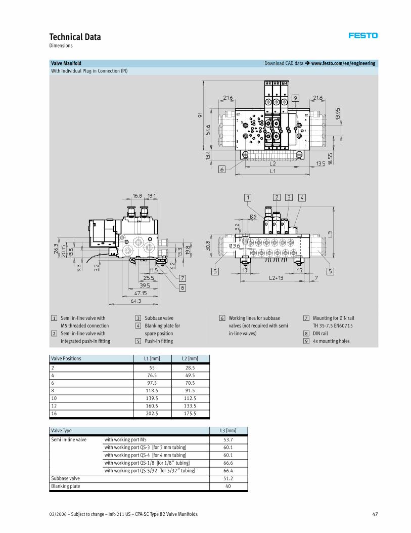
02/2006 – Subject to change – Info 211 US – CPA-SC Type 82 Valve Manifolds 47
Technical DataDimensions
Valve Manifold Download CAD data� www.festo.com/en/engineering
With Individual Plug-in Connection (PI)
1 Semi in-line valve with
M5 threaded connection
2 Semi in-line valve with
integrated push-in fitting
3 Subbase valve
4 Blanking plate for
spare position
5 Push-in fitting
6 Working lines for subbase
valves (not required with semi
in-line valves)
7 Mounting for DIN rail
TH 35-7.5 EN60715
8 DIN rail
9 4x mounting holes
Valve Positions L1 [mm] L2 [mm]
2 55 28.5
4 76.5 49.5
6 97.5 70.5
8 118.5 91.5
10 139.5 112.5
12 160.5 133.5
16 202.5 175.5
Valve Type L3 [mm]
Semi in-line valve with working port M5 53.7
with working port QS-3 [for 3 mm tubing] 60.1
with working port QS-4 [for 4 mm tubing] 60.1
with working port QS-1/8 [for 1/8� tubing] 66.6
with working port QS-5/32 [for 5/32� tubing] 66.4
Subbase valve 51.2
Blanking plate 40

CPA-SC Type 82 Valve Manifolds – Info 211 US – Subject to change – 02/200648
Technical DataDimensions
Valve Manifold Download CAD data� www.festo.com/en/engineering
With Individual Horizontal Connection (HC)
1 Semi in-line valve with
M5 threaded connection
2 Semi in-line valve with
integrated push-in fitting
3 Subbase valve
4 Blanking plate for
spare position
5 Push-in fitting
6 Working lines for subbase
valves (not required with semi
in-line valves)
7 Mounting for DIN rail
TH 35-7.5 EN60715
8 DIN rail
9 4x mounting holes
aJ Silencer for exhaust air
Valve Positions L1 [mm] L2 [mm]
2 54.5 29
4 75.5 50
6 96.5 71
8 117.5 92
10 138.5 113
12 159.5 134
16 201.5 176
Valve Type L3 [mm]
Semi in-line valve with working port M5 42.9
with working port QS-3 [for 3 mm tubing] 49.3
with working port QS-4 [for 4 mm tubing] 49.3
with working port QS-1/8 [for 1/8� tubing] 55.8
with working port QS-5/32 [for 5/32� tubing] 55.6
Subbase valve 40.4
Blanking plate 29.2

02/2006 – Subject to change – Info 211 US – CPA-SC Type 82 Valve Manifolds 49
Technical DataDimensions
Valve Manifold with Fieldbus Connection Download CAD data� www.festo.com/en/engineering
1 Semi in-line valve with
M5 threaded connection
2 Semi in-line valve with
integrated push-in fitting
3 Subbase valve
4 Blanking plate for
spare position
5 Push-in fitting
6 Working lines for subbase
valves (not required with semi
in-line valves)
7 Mounting for DIN rail
TH 35-7.5 EN60715
8 DIN rail
9 4x mounting holes
Valve Positions L1 [mm] L2 [mm]
4 127.2 49.5
6 148.2 70.5
8 169.2 91.5
10 190.2 112.5
12 211.2 133.5
16 253.2 175.5
20 295.2 217.5
24 337.2 259.5
Valve Type L3 [mm]
Semi in-line valve with working port M5 53.9
with working port QS-3 [for 3 mm tubing] 60.3
with working port QS-4 [for 4 mm tubing] 67.3
with working port QS-1/8 [for 1/8� tubing] 66.8
with working port QS-5/32 [for 5/32� tubing] 66.6
Subbase valve 51.4
Blanking plate 40.2

CPA-SC Type 82 Valve Manifolds – Info 211 US – Subject to change – 02/200650
Ordering DataMultipin Connection, Electrical Section
Mandatory Data0M �
Module No. Valve
Manifold
Size Power
Supply
Electrical
Connection
Position of
Working
Ports
Type of
Working
Ports
Manual
Override
Pneumatic
Supply
Pneumatic
Supply
Connection
Type of
Connections
529045 82P 10 1 MS
MF
P
A
B
E
F
I
J
N
V
S
T
V
X
L
R
B
H
G
D
Ordering
Example
529045 82P – 10 – 1 – – –
1 2 3 4 5 6 7 8 9 10 11
Ordering Table
Size 10 Conditions Code Enter
Code
0M 1 Module No. 529045
2 Valve Manifold Valve manifold type 82, Smart Cubic, CPA-SC 82P 82P
3 Size [mm] 10 -10 -10
4 Power Supply Power supply for valves, 24 V DC -1 -1
5 Electrical Connection Multi-pin plug connection for Sub-D, 25-pin 1 MS
Multi-pin plug connection for flat cable, 26-pin 2 MF
6 Position of Working Ports Working ports on valve -Pg
Working ports on subbase -A
7 Type of Working Ports M5 Threaded connection Byp g
QS-3 Push-in fitting [3 mm tubing connection] E
QS-4 Push-in fitting [4 mm tubing connection] F
QS-1/8 Push-in fitting [1/8 inch tubing connection] I
QS-5/32 Push-in fitting [5/32 inch tubing connection] J
8 Manual Override Manual override, push-in/detenting -N
Manual override blocked -V
9 Pneumatic Supply Internal pilot air supply, exhausting via silencer -S9 pp y
External pilot air supply, exhausting via silencer -T
Internal pilot air supply, ducted exhaust air -V
External pilot air supply, ducted exhaust air -X
10 Pneumatic Supply Connection Supply at left Lpp y
Position Supply at right R
Supply at both ends B
11 Type of Connections for Supply QS-8 Push-in fitting [8 mm tubing connection] Hyp pp y
QS-5/16 Push-in fitting [5/16 inch tubing connection] G
� Gx Threaded connection D
1 At least 2 valve positions must be equipped. 2 At least 4 valve positions must be equipped.

02/2006 – Subject to change – Info 211 US – CPA-SC Type 82 Valve Manifolds 51
Ordering DataMultipin Connection, Pneumatic Section
Mandatory Data0M Options0O
Equipment at Valve Position 0 … 19 User
Documentation
Accessories
12 Valves: M, J, N, K, B, G, E, X, I, L, V, W, R B, E, D, F, I, S, V H, …CP, …CQ, …CR,
13 Duct Separation, Duct 1, Valve Position 0 … 18: T
, , , , , , , , Q, ,
…CV, …CW, …CX, ,
0 1 2 3 4 5 6 7 8 9 10 11 12 13 14 15 16 17 18 19
– – +
12 + 13 14 15
Ordering Table
Size 10 Conditions Code Enter Code
� 12 Equipment at Valve Position 0 … 19 3 - -
0M Valves 5/2-way valve, single solenoid M Enter
5/2-way valve, double solenoid J equipment
2x 3/2-way valve, normally open N
q p
selection for
2x 3/2-way valve, normally closed K valve
5/3-way valve, mid-position pressurized B positions in
5/3-way valve, mid-position closed G
p
order code
5/3-way valve, mid-position exhausted E
3/2-way valve, normally closed, external supply air X
2x 2/2-way valve, normally closed, dual compressed air supply I
Spare position L
Duct separation, duct 3 separate 4 V
Duct separation, duct 5 separate 4 W
Duct separation, duct 3/5 separate 4 R
13 Duct Separation, Duct 1,
Valve Position 0 … 18
Duct 1 separate 4 T
14 User Documentation Express waiver - no manual to be included (already available) -B
Manuals, English -E
Manuals, German -D
Manuals, French -F
Manuals, Italian -I
Manuals, Spanish -S
Manuals, Swedish -V
0O 15 Accessories + +
DIN Rail Mounting 1 H
Connecting Cable, 2.5 m 1 … 99 5 …CPg ,
Sub-D, 25-pin 5 m 1 … 99 5 …CQ, p
(25-strand) 10 m 1 … 99 5 …CR
Connecting Cable, 2.5 m 1 … 99 5 …CVg ,
Sub-D, 25-pin 5 m 1 … 99 5 …CW, p
(12-strand) 10 m 1 … 99 5 …CX
3 Equipment at valve position 0 … 19
Max. number of coils: 20
Coil usage of the valves: I, J, K, L, N, B, E, G: 2 coils
M, X: 1 coil
With 4 … 12 valve positions: Only with valve M, N, K, X, I, L from position 9
With 4 … 16 valve positions: Only with valve M, N, K, X, I, L from position 5
With 4 … 20 valve positions: Only with valve M, N, K, X, I, L
4 Only with pneumatic supply connection B (pneumatic supply connection at both ends).
Only one duct separation per valve manifold can be selected for the supply and for the exhaust.
Duct separation T only is permissible at the first valve position.
Duct separation is not permissible at the last valve position.
5 Only in combination with electrical connection MS, whereby CV, CW and CX is only permissible with
2, 4 or 6 valve positions.
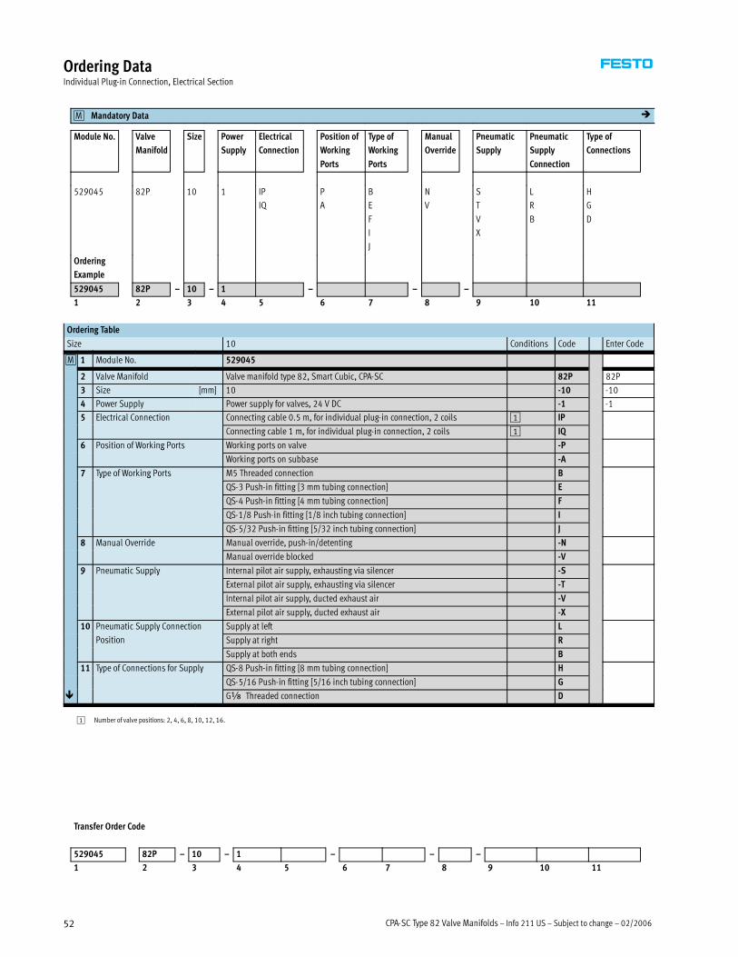
CPA-SC Type 82 Valve Manifolds – Info 211 US – Subject to change – 02/200652
Ordering DataIndividual Plug-in Connection, Electrical Section
Mandatory Data0M �
Module No. Valve
Manifold
Size Power
Supply
Electrical
Connection
Position of
Working
Ports
Type of
Working
Ports
Manual
Override
Pneumatic
Supply
Pneumatic
Supply
Connection
Type of
Connections
529045 82P 10 1 IP
IQ
P
A
B
E
F
I
J
N
V
S
T
V
X
L
R
B
H
G
D
Ordering
Example
529045 82P – 10 – 1 – – –
1 2 3 4 5 6 7 8 9 10 11
Ordering Table
Size 10 Conditions Code Enter Code
0M 1 Module No. 529045
2 Valve Manifold Valve manifold type 82, Smart Cubic, CPA-SC 82P 82P
3 Size [mm] 10 -10 -10
4 Power Supply Power supply for valves, 24 V DC -1 -1
5 Electrical Connection Connecting cable 0.5 m, for individual plug-in connection, 2 coils 1 IP
Connecting cable 1 m, for individual plug-in connection, 2 coils 1 IQ
6 Position of Working Ports Working ports on valve -Pg
Working ports on subbase -A
7 Type of Working Ports M5 Threaded connection Byp g
QS-3 Push-in fitting [3 mm tubing connection] E
QS-4 Push-in fitting [4 mm tubing connection] F
QS-1/8 Push-in fitting [1/8 inch tubing connection] I
QS-5/32 Push-in fitting [5/32 inch tubing connection] J
8 Manual Override Manual override, push-in/detenting -N
Manual override blocked -V
9 Pneumatic Supply Internal pilot air supply, exhausting via silencer -S9 pp y
External pilot air supply, exhausting via silencer -T
Internal pilot air supply, ducted exhaust air -V
External pilot air supply, ducted exhaust air -X
10 Pneumatic Supply Connection Supply at left Lpp y
Position Supply at right R
Supply at both ends B
11 Type of Connections for Supply QS-8 Push-in fitting [8 mm tubing connection] Hyp pp y
QS-5/16 Push-in fitting [5/16 inch tubing connection] G
� Gx Threaded connection D
1 Number of valve positions: 2, 4, 6, 8, 10, 12, 16.
Transfer Order Code
529045 82P – 10 – 1 – – –
1 2 3 4 5 6 7 8 9 10 11

02/2006 – Subject to change – Info 211 US – CPA-SC Type 82 Valve Manifolds 53
Ordering DataIndividual Plug-in Connection, Pneumatic Section
Mandatory Data0M Options0O
Equipment at Valve Position 0 … 15 User
Documentation
Accessories
12 Valves: M, J, N, K, B, G, E, X, I, L, V, W, R B, E, D, F, I, S, V H
13 Duct Separation, Duct 1, Valve Position 0 … 14: T
, , , , , ,
0 1 2 3 4 5 6 7 8 9 10 11 12 13 14 15
– – +
12 + 13 14 15
Ordering Table
Size 10 Conditions Code Enter Code
� 12 Equipment at Valve Position 0 … 15 - -
0M Valves 5/2-way valve, single solenoid M Enter
5/2-way valve, double solenoid J equipment
2x 3/2-way valve, normally open N
q p
selection for
2x 3/2-way valve, normally closed K valve
5/3-way valve, mid-position pressurized B positions in
5/3-way valve, mid-position closed G
p
order code
5/3-way valve, mid-position exhausted E
3/2-way valve, normally closed, external supply air X
2x 2/2-way valve, normally closed, dual compressed air supply I
Spare position L
Duct separation, duct 3 separate 2 V
Duct separation, duct 5 separate 2 W
Duct separation, duct 3/5 separate 2 R
13 Duct Separation, Duct 1,
Valve Position 0 … 14
Duct 1 separate 2 T
14 User Documentation Express waiver - no manual to be included (already available) -B
Manuals, English -E
Manuals, German -D
Manuals, French -F
Manuals, Italian -I
Manuals, Spanish -S
Manuals, Swedish -V
0O 15 Accessories + +
DIN Rail Mounting 1 H
2 Only with pneumatic supply connection B (pneumatic supply at both ends).
Only one duct separation per valve manifold can be selected for the supply and for the exhaust.
Duct separation T only is permissible at the first valve position.
Duct separation is not permissible at the last valve position.
Transfer Order Code
0 1 2 3 4 5 6 7 8 9 10 11 12 13 14 15
– – +
12 + 13 14 15
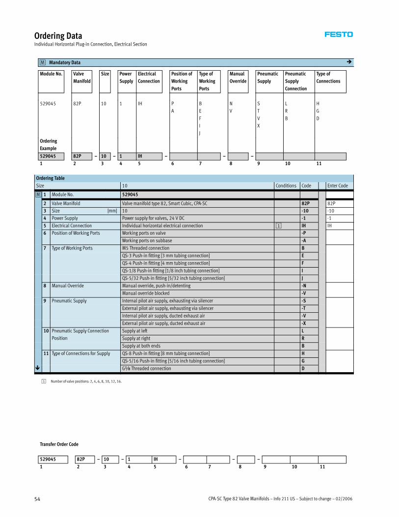
CPA-SC Type 82 Valve Manifolds – Info 211 US – Subject to change – 02/200654
Ordering DataIndividual Horizontal Plug-in Connection, Electrical Section
Mandatory Data0M �
Module No. Valve
Manifold
Size Power
Supply
Electrical
Connection
Position of
Working
Ports
Type of
Working
Ports
Manual
Override
Pneumatic
Supply
Pneumatic
Supply
Connection
Type of
Connections
529045 82P 10 1 IH P
A
B
E
F
I
J
N
V
S
T
V
X
L
R
B
H
G
D
Ordering
Example
529045 82P – 10 – 1 IH – – –
1 2 3 4 5 6 7 8 9 10 11
Ordering Table
Size 10 Conditions Code Enter Code
0M 1 Module No. 529045
2 Valve Manifold Valve manifold type 82, Smart Cubic, CPA-SC 82P 82P
3 Size [mm] 10 -10 -10
4 Power Supply Power supply for valves, 24 V DC -1 -1
5 Electrical Connection Individual horizontal electrical connection 1 IH IH
6 Position of Working Ports Working ports on valve -Pg
Working ports on subbase -A
7 Type of Working Ports M5 Threaded connection Byp g
QS-3 Push-in fitting [3 mm tubing connection] E
QS-4 Push-in fitting [4 mm tubing connection] F
QS-1/8 Push-in fitting [1/8 inch tubing connection] I
QS-5/32 Push-in fitting [5/32 inch tubing connection] J
8 Manual Override Manual override, push-in/detenting -N
Manual override blocked -V
9 Pneumatic Supply Internal pilot air supply, exhausting via silencer -S9 pp y
External pilot air supply, exhausting via silencer -T
Internal pilot air supply, ducted exhaust air -V
External pilot air supply, ducted exhaust air -X
10 Pneumatic Supply Connection Supply at left Lpp y
Position Supply at right R
Supply at both ends B
11 Type of Connections for Supply QS-8 Push-in fitting [8 mm tubing connection] Hyp pp y
QS-5/16 Push-in fitting [5/16 inch tubing connection] G
� Gx Threaded connection D
1 Number of valve positions: 2, 4, 6, 8, 10, 12, 16.
Transfer Order Code
529045 82P – 10 – 1 IH – – –
1 2 3 4 5 6 7 8 9 10 11
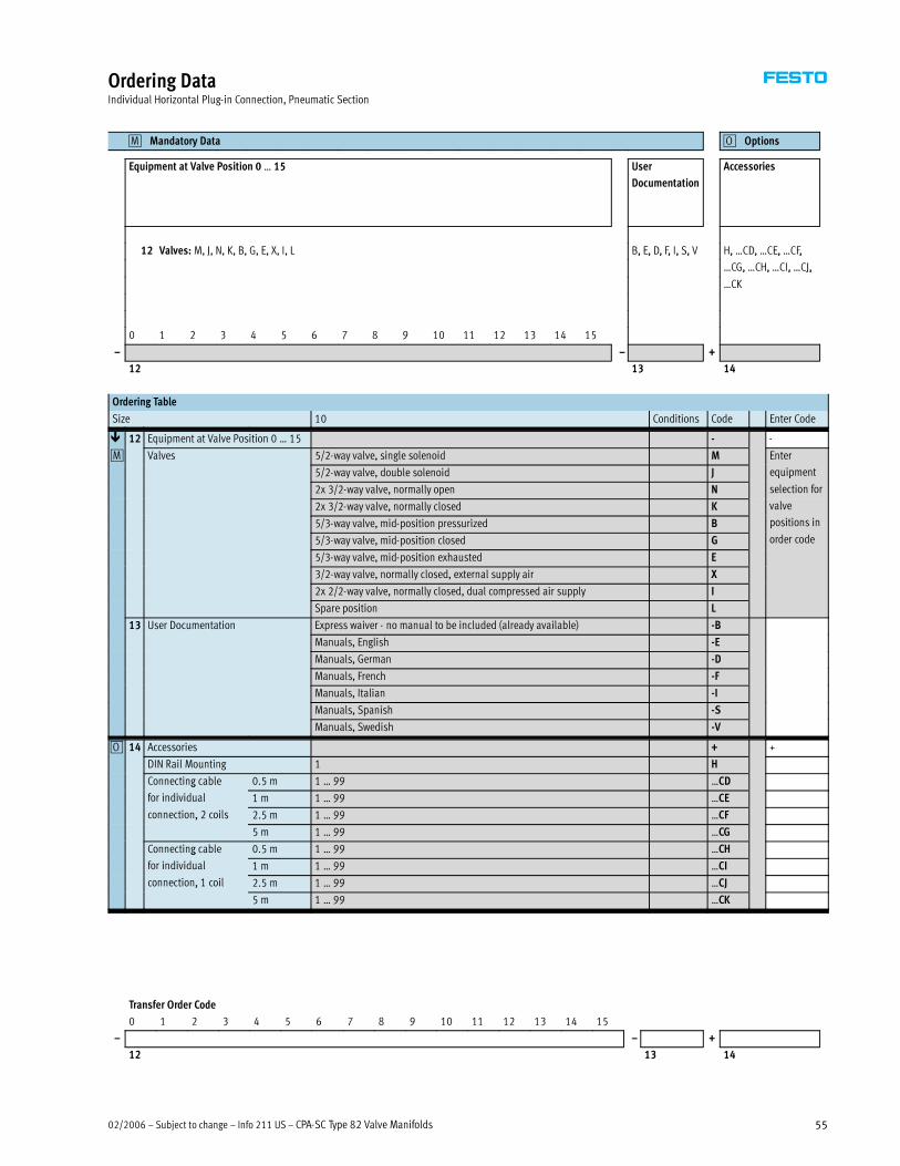
02/2006 – Subject to change – Info 211 US – CPA-SC Type 82 Valve Manifolds 55
Ordering DataIndividual Horizontal Plug-in Connection, Pneumatic Section
Mandatory Data0M Options0O
Equipment at Valve Position 0 … 15 User
Documentation
Accessories
12 Valves: M, J, N, K, B, G, E, X, I, L B, E, D, F, I, S, V H, …CD, …CE, …CF,, , , , , , , , , ,
…CG, …CH, …CI, …CJ,, , , J,
…CK
0 1 2 3 4 5 6 7 8 9 10 11 12 13 14 15
– – +
12 13 14
Ordering Table
Size 10 Conditions Code Enter Code
� 12 Equipment at Valve Position 0 … 15 - -
0M Valves 5/2-way valve, single solenoid M Enter
5/2-way valve, double solenoid J equipment
2x 3/2-way valve, normally open N
q p
selection for
2x 3/2-way valve, normally closed K valve
5/3-way valve, mid-position pressurized B positions in
5/3-way valve, mid-position closed G
p
order code
5/3-way valve, mid-position exhausted E
3/2-way valve, normally closed, external supply air X
2x 2/2-way valve, normally closed, dual compressed air supply I
Spare position L
13 User Documentation Express waiver - no manual to be included (already available) -B
Manuals, English -E
Manuals, German -D
Manuals, French -F
Manuals, Italian -I
Manuals, Spanish -S
Manuals, Swedish -V
0O 14 Accessories + +
DIN Rail Mounting 1 H
Connecting cable 0.5 m 1 … 99 …CDg
for individual 1 m 1 … 99 …CE
connection, 2 coils 2.5 m 1 … 99 …CF,
5 m 1 … 99 …CG
Connecting cable 0.5 m 1 … 99 …CHg
for individual 1 m 1 … 99 …CI
connection, 1 coil 2.5 m 1 … 99 …CJ,
5 m 1 … 99 …CK
Transfer Order Code
0 1 2 3 4 5 6 7 8 9 10 11 12 13 14 15
– – +
12 13 14

CPA-SC Type 82 Valve Manifolds – Info 211 US – Subject to change – 02/200656
Ordering DataManifold with Individual Subbase, Electrical Section
Mandatory Data0M �
Module No. Valve
Manifold
Size Power
Supply
Electrical
Connection
Position of
Working
Ports
Type of
Working
Ports
Manual
Override
Pneumatic
Supply
Pneumatic
Supply
Connection
Type of
Connections
529045 82P 10 1 SP
SQ
SH
P
A
B
E
F
I
J
N
V
S
T
V
X
L B
F
J
Ordering
Example
529045 82P – 10 – 1 – – – L
1 2 3 4 5 6 7 8 9 10 11
Ordering Table
Size 10 Conditions Code Enter Code
0M 1 Module No. 529045
2 Valve Manifold Valve manifold type 82, Smart Cubic, CPA-SC 82P 82P
3 Size [mm] 10 -10 -10
4 Power Supply Power supply for valves, 24 V DC -1 -1
5 Electrical Connection Individual plug-in subbase, connecting cable 0.5 m 1 SP
Individual plug-in subbase, connecting cable 1 m 1 SQ
Individual subbase, horizontal connection 1 SH
6 Position of Working Ports Working ports on valve -Pg
Working ports on subbase -A
7 Type of Working Ports M5 Threaded connection Byp g
QS-3 Push-in fitting [3 mm tubing connection] E
QS-4 Push-in fitting [4 mm tubing connection] F
QS-1/8 Push-in fitting [1/8 inch tubing connection] I
QS-5/32 Push-in fitting [5/32 inch tubing connection] J
8 Manual Override Manual override, push-in/detenting -N
Manual override blocked -V
9 Pneumatic Supply Internal pilot air supply, exhausting via silencer -S9 pp y
External pilot air supply, exhausting via silencer -T
Internal pilot air supply, ducted exhaust air -V
External pilot air supply, ducted exhaust air -X
10 Pneumatic Supply Connection
Position
Supply at left L L
11 Type of Connections for Supply M5 Threaded connection Byp pp y
QS-4 Push-in fitting [4 mm tubing connection] F
� QS-5/32 Push-in fitting [5/32 inch tubing connection] J
1 No user documentation selectable.
Transfer Order Code
529045 82P – 10 – 1 – – – L
1 2 3 4 5 6 7 8 9 10 11
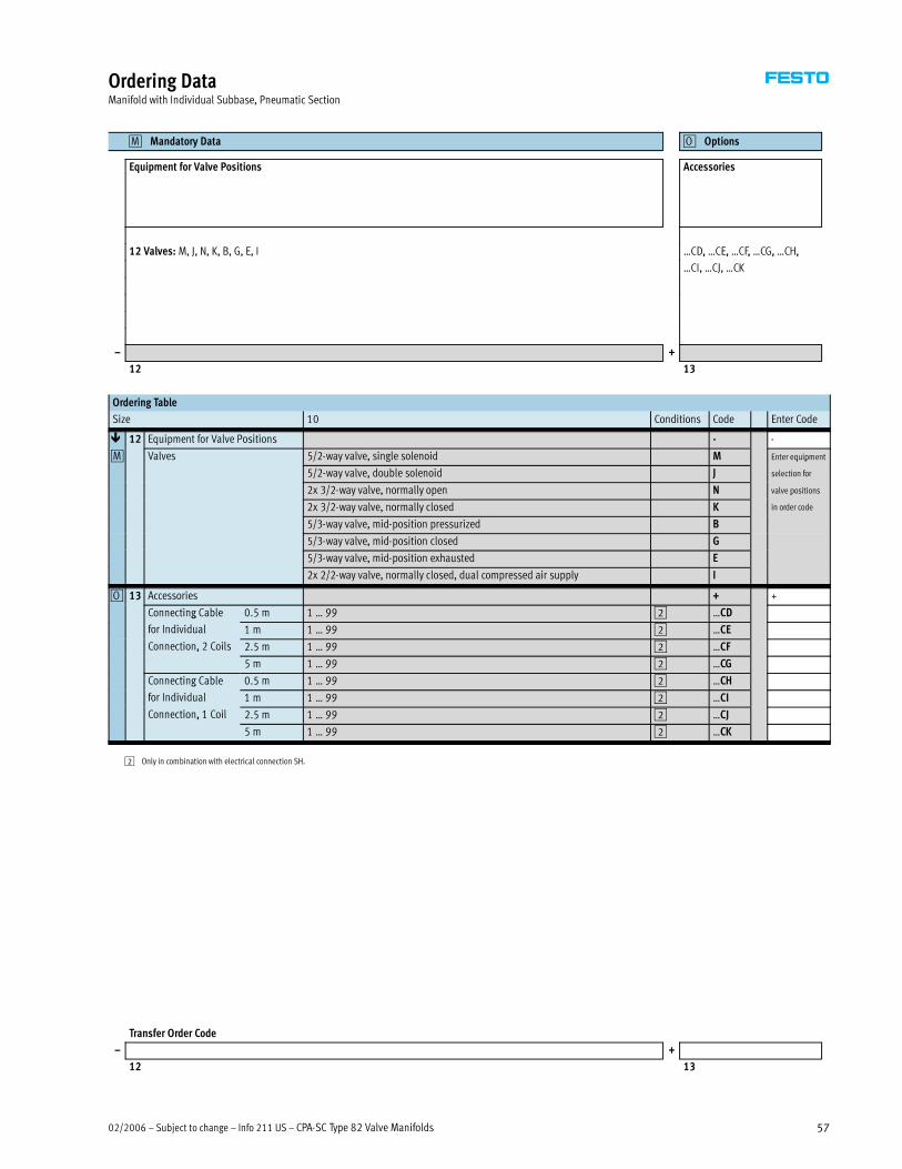
02/2006 – Subject to change – Info 211 US – CPA-SC Type 82 Valve Manifolds 57
Ordering DataManifold with Individual Subbase, Pneumatic Section
Mandatory Data0M Options0O
Equipment for Valve Positions Accessories
12 Valves: M, J, N, K, B, G, E, I …CD, …CE, …CF, …CG, …CH,, , , , ,
…CI, …CJ, …CK
– +
12 13
Ordering Table
Size 10 Conditions Code Enter Code
� 12 Equipment for Valve Positions - -
0M Valves 5/2-way valve, single solenoid M Enter equipment
5/2-way valve, double solenoid J
q p
selection for
2x 3/2-way valve, normally open N valve positions
2x 3/2-way valve, normally closed K
p
in order code
5/3-way valve, mid-position pressurized B
5/3-way valve, mid-position closed G
5/3-way valve, mid-position exhausted E
2x 2/2-way valve, normally closed, dual compressed air supply I
0O 13 Accessories + +
Connecting Cable 0.5 m 1 … 99 2 …CDg
for Individual 1 m 1 … 99 2 …CE
Connection, 2 Coils 2.5 m 1 … 99 2 …CF,
5 m 1 … 99 2 …CG
Connecting Cable 0.5 m 1 … 99 2 …CHg
for Individual 1 m 1 … 99 2 …CI
Connection, 1 Coil 2.5 m 1 … 99 2 …CJ,
5 m 1 … 99 2 …CK
2 Only in combination with electrical connection SH.
Transfer Order Code
– +
12 13

CPA-SC Type 82 Valve Manifolds – Info 211 US – Subject to change – 02/200658
Ordering DataManifold with DeviceNet, Electrical Section
Mandatory Data0M �
Module No. Valve
Manifold
Size Electrical
Connection
Position of
Working Ports
Type of
Working Ports
Manual
Override
Pneumatic
Supply
Pneumatic
Supply
Connection
Type of
Connections
538509 82P 10 DN P
A
B
E
F
I
J
N
V
S
T
V
X
L
R
B
B
F
H
G
D
Ordering
Example
538509 82P – 10 – DN – P E – N – S B D
1 2 3 4 5 6 7 8 9 10
Ordering Table
Size 10 Conditions Code Enter Code
0M 1 Module No. 538509
2 Valve Manifold Valve manifold type 82, Smart Cubic, CPA-SC 82P 82P
3 Size [mm] 10 -10 -10
4 Electrical Connection DeviceNet -DN -DN
5 Position of Working Ports Working ports on valve -Pg
Working ports on subbase -A
6 Type of Working Ports M5 Threaded connection Byp g
QS-3 Push-in fitting [3 mm tubing connection] E
QS-4 Push-in fitting [4 mm tubing connection] F
QS-1/8 Push-in fitting [1/8 inch tubing connection] I
QS-5/32 Push-in fitting [5/32 inch tubing connection] J
7 Manual Override Manual override, push-in/detenting -N
Manual override blocked -V
8 Pneumatic Supply Internal pilot air supply, exhausting via silencer -Spp y
External pilot air supply, exhausting via silencer -T
Internal pilot air supply, ducted exhaust air -V
External pilot air supply, ducted exhaust air -X
9 Pneumatic Supply Connection Supply at left L9 pp y
Position Supply at right R
Supply at both ends B
10 Type of Connections for Supply M5 Threaded connection Byp pp y
QS-4 Push-in fitting [4 mm tubing connection] F
QS-8 Push-in fitting [8 mm tubing connection] H
QS-5/16 Push-in fitting [5/16 inch tubing connection] G
� Gx Threaded connection D
Transfer Order Code
538509 82P – 10 – DN – – –
1 2 3 4 5 6 7 8 9 10

02/2006 – Subject to change – Info 211 US – CPA-SC Type 82 Valve Manifolds 59
Ordering DataManifold with DeviceNet, Pneumatic Section
Mandatory Data0M Options0O
Equipment at Valve Position 0 … 23 User
Documentation
Accessories
11 Valves: M, J, N, K, B, G, E, X, I, L, V, W, R E, D, F, I, S, V H, …D, …M
12 Duct Separation, Duct 1, Valve Position 0 … 22: T
, , , , ,
Valve Position
0 1 2 3 4 5 6 7 8 9 10 11 12 13 14 15 16 17 18 19 20 21 22 23
– – +
11 + 12 13 14
Ordering Table
Size 10 Conditions Code Enter Code
� 11 Equipment at Valve Position 0 … 23 1 - -
0M Valves 5/2-way valve, single solenoid M Enter
5/2-way valve, double solenoid J equipment
2x 3/2-way valve, normally open N
q p
selection for
2x 3/2-way valve, normally closed K valve
5/3-way valve, mid-position pressurized B positions in
5/3-way valve, mid-position closed G
p
order code
5/3-way valve, mid-position exhausted E
3/2-way valve, normally closed, external supply air X
2x 2/2-way valve, normally closed, dual compressed air supply I
Spare position L
Duct separation, duct 3 separate 2 V
Duct separation, duct 5 separate 2 W
Duct separation, duct 3/5 separate 2 R
12 Duct Separation, Duct 1, Valve
Position 0 … 22
Duct 1 separate 2 T
13 User Documentation Manuals, English -E
Manuals, German -D
Manuals, French -F
Manuals, Italian -I
Manuals, Spanish -S
Manuals, Swedish -V
0O 14 Accessories + +
DIN Rail Mounting 1 H
Connector Plug Straight 1 … 99 …Dg
DeviceNet B-coded 1 … 99 …M
1 Equipment at valve Position 0 … 23
Max. number of coils: 32
Coil usage of the valves: I, J, K, L, N, B, E, G: 2 coils
M, X: 1 coil
2 Only with pneumatic supply connection B (pneumatic supply connection at both ends).
Only one duct separation per valve manifold can be selected for the supply and for the exhaust.
Duct separation T only is permissible at the first valve position. Duct separation is not permissible
at the last valve position.
Transfer Order Code
0 1 2 3 4 5 6 7 8 9 10 11 12 13 14 15 16 17 18 19 20 21 22 23
– – +
11 + 12 13 14

CPA-SC Type 82 Valve Manifolds – Info 211 US – Subject to change – 02/200660
Ordering DataReplacement Valves
Valves
Electrical Plug-in Connection Electrical Horizontal Connection
Code Valve Function Type Part No. Type Part No.
Subbase Valve
M 5/2-way valve, single solenoid CPASC1-M1H-M-P-2.5 526990 CPASC1-M1H-M-H-2.5 527008
J 5/2-way valve, double solenoid CPASC1-M1H-J-P-2.5 526992 CPASC1-M1H-J-H-2.5 527010
N 2x 3/2-way valve,
normally open
CPASC1-M1H-N-P-2.5 526994 CPASC1-M1H-N-H-2.5 527012
K 2x 3/2-way valve,
normally closed
CPASC1-M1H-K-P-2.5 526996 CPASC1-M1H-K-H-2.5 527014
B 5/3-way valve,
mid-position pressurized
CPASC1-M1H-B-P-2.5 526998 CPASC1-M1H-B-H-2.5 527016
G 5/3-way valve,
mid-position closed
CPASC1-M1H-G-P-2.5 527000 CPASC1-M1H-G-H-2.5 527018
E 5/3-way valve,
mid-position exhausted
CPASC1-M1H-E-P-2.5 527002 CPASC1-M1H-E-H-2.5 527020
X 1x 3/2-way valve CPASC1-M1H-X-P-2.5 527004 CPASC1-M1H-X-H-2.5 527022
I 2x 2/2-way valve CPASC1-M1H-I-P-2.5 527006 CPASC1-M1H-I-H-2.5 527024
Semi In-line Valve with M5 Working Ports
M 5/2-way valve, single solenoid CPPSC1-M1H-M-P-M5 527294 CPPSC1-M1H-M-H-M5 527303
J 5/2-way valve, double solenoid CPPSC1-M1H-J-P-M5 527295 CPPSC1-M1H-J-H-M5 527304
N 2x 3/2-way valve,
normally open
CPPSC1-M1H-N-P-M5 527296 CPPSC1-M1H-N-H-M5 527305
K 2x 3/2-way valve,
normally closed
CPPSC1-M1H-K-P-M5 527297 CPPSC1-M1H-K-H-M5 527306
B 5/3-way valve,
mid-position pressurized
CPPSC1-M1H-B-P-M5 527298 CPPSC1-M1H-B-H-M5 527307
G 5/3-way valve,
mid-position closed
CPPSC1-M1H-G-P-M5 527299 CPPSC1-M1H-G-H-M5 527308
E 5/3-way valve,
mid-position exhausted
CPPSC1-M1H-E-P-M5 527300 CPPSC1-M1H-E-H-M5 527309
X 1x 3/2-way valve CPPSC1-M1H-X-P-M5 527301 CPPSC1-M1H-X-H-M5 527310
I 2x 2/2-way valve CPPSC1-M1H-I-P-M5 527302 CPPSC1-M1H-I-H-M5 527311
Semi In-line Valve with QS-3 Working Ports
M 5/2-way valve, single solenoid CPPSC1-M1H-M-P-Q3 527330 CPPSC1-M1H-M-H-Q3 527339
J 5/2-way valve, double solenoid CPPSC1-M1H-J-P-Q3 527331 CPPSC1-M1H-J-H-Q3 527340
N 2x 3/2-way valve,
normally open
CPPSC1-M1H-N-P-Q3 527332 CPPSC1-M1H-N-H-Q3 527341
K 2x 3/2-way valve,
normally closed
CPPSC1-M1H-K-P-Q3 527333 CPPSC1-M1H-K-H-Q3 527342
B 5/3-way valve,
mid-position pressurized
CPPSC1-M1H-B-P-Q3 527334 CPPSC1-M1H-B-H-Q3 527343
G 5/3-way valve,
mid-position closed
CPPSC1-M1H-G-P-Q3 527335 CPPSC1-M1H-G-H-Q3 527344
E 5/3-way valve,
mid-position exhausted
CPPSC1-M1H-E-P-Q3 527336 CPPSC1-M1H-E-H-Q3 527345
X 1x 3/2-way valve CPPSC1-M1H-X-P-Q3 527337 CPPSC1-M1H-X-H-Q3 527346
I 2x 2/2-way valve CPPSC1-M1H-I-P-Q3 527338 CPPSC1-M1H-I-H-Q3 527347
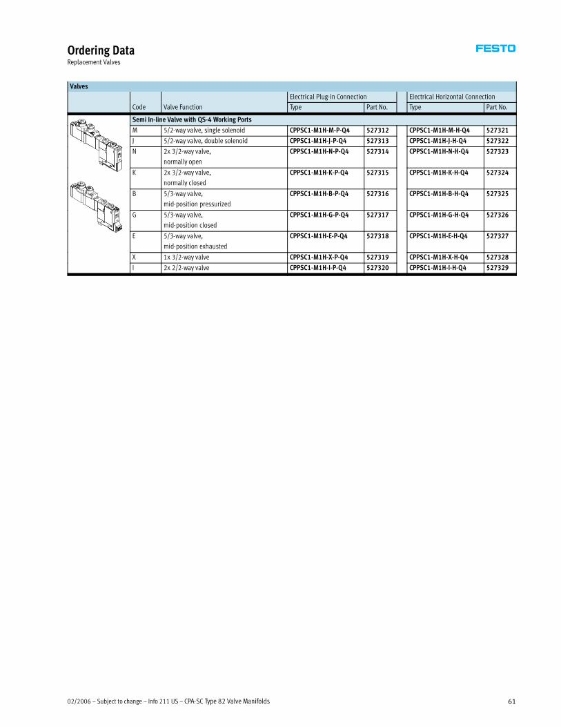
02/2006 – Subject to change – Info 211 US – CPA-SC Type 82 Valve Manifolds 61
Ordering DataReplacement Valves
Valves
Electrical Plug-in Connection Electrical Horizontal Connection
Code Valve Function Type Part No. Type Part No.
Semi In-line Valve with QS-4 Working Ports
M 5/2-way valve, single solenoid CPPSC1-M1H-M-P-Q4 527312 CPPSC1-M1H-M-H-Q4 527321
J 5/2-way valve, double solenoid CPPSC1-M1H-J-P-Q4 527313 CPPSC1-M1H-J-H-Q4 527322
N 2x 3/2-way valve,
normally open
CPPSC1-M1H-N-P-Q4 527314 CPPSC1-M1H-N-H-Q4 527323
K 2x 3/2-way valve,
normally closed
CPPSC1-M1H-K-P-Q4 527315 CPPSC1-M1H-K-H-Q4 527324
B 5/3-way valve,
mid-position pressurized
CPPSC1-M1H-B-P-Q4 527316 CPPSC1-M1H-B-H-Q4 527325
G 5/3-way valve,
mid-position closed
CPPSC1-M1H-G-P-Q4 527317 CPPSC1-M1H-G-H-Q4 527326
E 5/3-way valve,
mid-position exhausted
CPPSC1-M1H-E-P-Q4 527318 CPPSC1-M1H-E-H-Q4 527327
X 1x 3/2-way valve CPPSC1-M1H-X-P-Q4 527319 CPPSC1-M1H-X-H-Q4 527328
I 2x 2/2-way valve CPPSC1-M1H-I-P-Q4 527320 CPPSC1-M1H-I-H-Q4 527329

CPA-SC Type 82 Valve Manifolds – Info 211 US – Subject to change – 02/200662
AccessoriesElectrical Components
Ordering Data
Designation Type Part No.
Plug Socket with Cable for Plug-in Connection
For 1 coil 0.5 m MHAP-PI 197260
1 m MHAP-PI-1 532182
For 2 coils 0.5 m MHAP-PI-D-0.5 529116
1 m MHAP-PI-D-1 527395
Plug Socket with Cable for Horizontal Connection
For 1 coil, 2-wire 0.5 m KMH-0.5 197263,
1 m KMH-1 197264
2.5 m KMH-2.5 527400
5 m KMH-5 527401
For 2 coils, 3-wire 0.5 m KMH-D-0.5 527396, 3
1 m KMH-D-1 527397
2.5 m KMH-D-2.5 527398
5 m KMH-D-5 527399
Connecting Cable IP20
Sub-D, 25-pin, up to 20 coils 2.5 m KMP6-25P-20-2.5 530046, 5 p , p
5 m KMP6-25P-20-5 530047
10 m KMP6-25P-20-10 530048
Sub-D, 25-pin, up to 12 coils 2.5 m KMP6-25P-12-2.5 530049, 5 p , p
5 m KMP6-25P-12-5 530050
10 m KMP6-25P-12-10 530051
Power Supply
MicroStyle M12, 5-pin socket (B-coded) for 0.75 mm2 NTSD-GD-9-M12-5POL-RK 538999
Fieldbus Connection
Fieldbus socket for MicroStyle connection, M12, socket
(A-coded)
FBSD-GD-9-5POL 18324
Valve Terminal Connection
Angled plug – angled socket WS-WD 0.5 m KVI-CP-1-WS-WD-0.5 178564g p g g
2 m KVI-CP-1-WS-WD-2 163139
5 m KVI-CP-1-WS-WD-5 163138
Plug straight GS-WD 5 m KVI-CP-1-GS-WD-5 163137
8 m KVI-CP-1-GS-WD-8 163136
Plug straight GS-GD 2 m, for chain link trunking KVI-CP-2-GS-GD-2 170234g g
5 m, for chain link trunking KVI-CP-2-GS-GD-5 170235
8 m, for chain link trunking KVI-CP-2-GS-GD-8 165616

02/2006 – Subject to change – Info 211 US – CPA-SC Type 82 Valve Manifolds 63
AccessoriesTube Fittings
Ordering Data
Designation Type Part No.
Push-in Fittings for Working Ports
Connecting thread M5 for tubing O.D. 3 mm QSM-M5-3 153302g 5 g
4 mm QSM-M5-4 153304
3 mm QSM-M5-3-I 153313
4 mm QSM-M5-4-I 153315
Push-in L-fittings for Working Ports
Connecting thread M5 for tubing O.D. 3 mm QSML-M5-3 153331g 5 g
4 mm QSML-M5-4 153333
6 mm QSML-M5-6 153335
4 mm QSMLL-M5-4 153339
6 mm QSMLL-M5-6 153341
Push-in Fittings for Manifolds
Connecting thread M3 for tubing O.D. 3 mm QSM-M3-3 153301g 3 g
4 mm QSM-M3-4 153303
3 mm QSM-M3-3-I 153312
4 mm QSM-M3-4-I 153314
Connecting thread M5 for tubing O.D. 3 mm QSM-M5-3 153302g 5 g
4 mm QSM-M5-4 153304
6 mm QSM-M5-6 153306
3 mm QSM-M5-3-I 153313
4 mm QSM-M5-4-I 153315
6 mm QSM-M5-6-I 153317
Connecting thread Gx for tubing O.D. 5/32 inch QSM-M5-5/32-I-U-M 130593g x g1/4 inch QSM-M5-1/4-I-U-M 1305911/8 inch QSM-M5-1/8-I-U-M 1307493/16 inch QSM-M5-3/16-I-U-M 1837501/4 inch QS-M5-1/4-I-U-M 192808
4 mm QSM-Gx-4-I 186266
6 mm QSM-Gx-6-I 186267
8 mm QS-Gx-8-I 186109
Connecting thread Rx for tubing O.D. 4 mm QSM-x-4 153305g x g
6 mm QSM-x-6 153307
4 mm QSM-x-4-I 153316
6 mm QSM-x-6-I 153318
Push-in L-fittings for Manifolds
Connecting thread M3 for tubing O.D. 3 mm QSML-M3-3 153330g 3 g
4 mm QSML-M3-4 153332
3 mm QSMLL-M3-3 153337
4 mm QSMLL-M3-4 153338
Connecting thread M5 for tubing O.D. 3 mm QSML-M5-3 153331g 5 g
4 mm QSML-M5-4 153333
6 mm QSML-M5-6 153335
4 mm QSMLL-M5-4 153339
6 mm QSMLL-M5-6 153341
Connecting thread Rx for tubing O.D. 4 mm QSML-x-4 153334g x g
6 mm QSML-x-6 153336
4 mm QSMLL-x-4 153340
6 mm QSMLL-x-6 153342

CPA-SC Type 82 Valve Manifolds – Info 211 US – Subject to change – 02/200664
AccessoriesMiscellaneous
Ordering Data
Designation Type Part No.
Silencers
Connecting thread M3 U-M3 163978g
M5 U-M5 4645
M5 UC-M5 165003
Gx UC-x 161419
Connection type, push-in sleeve 3 mm UC-QS-3H 165005yp , p
4 mm UC-QS-4H 165006
6 mm UC-QS-6H 165007
8 mm UC-QS-8H 175611
Blanking Plugs
M5 Thread B-M5 3843
M5 Thread B-M5-B 174308
Gx Thread B-x 3568
Plugs
Blanking plug for tubing O.D. 3 mm QSMC-3H 153382g p g g
4 mm QSC-4H 153267
6 mm QSC-6H 153268
8 mm QSC-8H 153269
Labels
6x10 in frames, 64 pieces for valve identification IBS-6x10 18576
4.5x9 mm, 80 pieces for manifold block identification MH-BZ-80x 197259
Mounting
For DIN rail CPASC1-BG-NRH 527392
Cover
Cover for vacant position (one self adhesive label supplied) CPASC1-RP 527062
Cover for manual override CPASC1-MO-V 527393
Valve Seal
For manifold block CPASC1-SEAL-A 527394
Separator Element and Assembly Tool
Separator element CPASC1-KT 536942
Assembly tool for separator element CPASC1-MWKT 536943
User Documentation
User documentation – CPA-SC English P.BE-CPASC-EN 530933
German P.BE-CPASC-DE 530932
French P.BE-CPASC-FR 530934
Spanish P.BE-CPASC-ES 530935
Italian P.BE-CPASC-IT 530936
Swedish P.BE-CPASC-SV 530937
User documentation – Fieldbus DeviceNet English P.BE-CPASC-CPVSC-DN-EN 539009
German P.BE-CPASC-CPVSC-DN-DE 539008
French P.BE-CPASC-CPVSC-DN-FR 539010
Spanish P.BE-CPASC-CPVSC-DN-ES 539011
Italian P.BE-CPASC-CPVSC-DN-IT 539012
Swedish P.BE-CPASC-CPVSC-DN-SV 539013
Software
Software – CD-ROM Valve terminals P.CD-VALVE-T 183350
Utilities P.CD-VI-UTILITIES-2 533500
02/2006 – Subject to change – Info 211 US – CPA-SC Type 82 Valve Manifolds 65
Operating Recommendations
Compressed Air
Operate your equipment with
unlubricated compressed air if
possible. Festo valves and cylinders
are designed for operation under
normal use without any additional
lubrication, yet still have a long
service life. The quality of compressed
air downstream of the compressor
must correspond to that of
unlubricated compressed air.
If possible, do not operate all of
your equipment with lubricated
compressed air. The lubricators
should, where possible, always be
located downstream of the valves,
directly upstream of the cylinders
used.
Incorrect additional oil and too high
an oil content in the compressed air
reduces the service life of the valve
terminal. Use Festo special oil
OFSW-32, P/N 152811 (1 liter)
(as specified in DIN 51524-HLP32;
basic oil viscosity 32 cSt at 40�C).
Biodegradable Oils
When using bio-oils (oils which are
based upon synthetic or native ester,
e.g. rapeseed oil methyl ester), the
maximum residual oil content of
0.1 mg/m�must not be exceeded
(see ISO 8573-1 Class 4).
Mineral Oils
When using mineral oils (e.g. HLP oils
to DIN 51524, parts 1 to 3) or similar
oils based on poly-alpha-olefins
(PAO), the maximum residual oil
content of 5 mg/m�must not be
exceeded (see ISO 8573-1 Class 4).
A higher residual oil content
irrespective of the compressor oil
cannot be permitted, as the basic
lubricant would be washed away
over time.

CPA-SC Type 82 Valve Manifold – Info 211 US – Subject to change – 02/200666
� Design, documentation, assembly/testing
� Single and multi-axis linear
and rotary systems
� Stepper controls, servo pneumatic and
servo electric systems
� Design, documentation, assembly/testing
� Cabinets are designed, manufactured,
assembled, and tested per NEMA, UL,
and IEC standards
� Standard and stainless steel enclosures
Festo Product Range
Integrated Systems Control Systems
� ISO and NFPA cylinders
� Linear and rotary actuators
� Standard, precision, and
micro grippers plus accessories
Pneumatic Actuators and Grippers
� Belt and ball screw driven linear actuators
� High accuracy and repeatability
� High rigidity and speed
Electromechanical Actuators
Valves� In-line/sub-base directional control valves
� OSHA compliant lockout valves
� Proportional valves
Valve Manifolds� Direct, multi-pin, and fieldbus manifolds
Pneumatic Valves and Valve Manifolds
� Inductive, optical, mechanical,
pressure and vacuum sensors
� PLCs and IPCs
� Remote access panels [HMI]
� Counters, timers and gauges
Sensors and Control Technology
� Filters
� Regulators
� Lubricators
� Dryers
� Combination units
Air Preparation
� Vacuum generators
� Suction cups and suction grippers
� A variety of suction cup types
and materials are available
Vacuum Components
� Inch/metric fittings, hybrid
fittings, and flow controls
� Inch/metric tubing
(various materials and colors)
Fittings and Tubing
� Cylinders, manifolds, tubing and fittings
for use in washdown environments
� Linear/rotary actuators with and
without a process valve;
diaphragm valves, Namur valves
Industry Specific Solutions
For more information about the entire Festo product range, including
technical specifications, CAD models, product selection software,
and access to our on-line store, visit us at www.festo.com/us.

While every effort is made
to ensure that all dimensions
and specifications are correct,
any printing errors not rectified
are outside the control of Festo,
who cannot be held responsible
for the same. For Liability and
Warranty conditions, refer to
our standard “Conditions of
Sale”, available on request
from your local Festo office.
All rights reserved. No part
of this publication may be
reproduced or transmitted
in any form or by any means,
electronic, mechanical,
photocopying or otherwise,
without the prior written
permission of Festo.
All technical data subject
to change according to
technical update.
© Copyright 2006, Festo Corporation
Length or Distance
m > ft = x 3.281
mm > inch = ÷ 25.4
Volume
cm³ > in³ = x 0.061
Mass
g > lb = x 0.002
kg > lb = x 2.2046
Pressure
bar > psi = x 14.7
Temperature
C° > F° = x [1.8] + 32
Flow
l/min > Cv = x 0.001
l/min > scfm = x 0.0353
Force
N > lbf = x 0.2248
kgf > N = x 9.80665
Moment
Nm > in-lb = x 8.8507
Nm > ft-lb = x 0.7376
Moment of Inertia
kg·cm² > lb-in² = x 0.3417
kg·m > lb-ft = x 7.233
kg·m² > oz-in² = x 5.4675
Conversion FactorsThe conversion table belowincludes the units most commonlyused for designing a system.They are given to enable the userto make necessary calculations.

United States
For ordering and product assistance,
or to find your nearest Festo Distributor
in the USA, contact us via:
Phone: 1.800.99.FESTO
Fax: 1.800.96.FESTO
Email: [email protected]
www.festo.com/us
Customer Resource Center502 Earth City ExpresswaySuite 125Earth City, MO 63045Call Toll-free: 1.800.993.3786Fax Toll-free: 1.800.963.3786
HeadquartersFesto Corporation395 Moreland RoadP.O. Box 18023Hauppauge, NY 11788
Sales Offices
Boston120 Presidential WaySuite 330Woburn, MA 01801
Charlotte4301-S Stuart Andrew Blvd.Charlotte, NC 28217
Chicago1441 East Business Center DriveMt. Prospect, IL 60056
Dallas1825 Lakeway DriveSuite 600Lewisville, TX 75057
Detroit1228 Kirts Blvd.Suite 400Troy, MI 48084
New York395 Moreland RoadHauppauge, NY 11788
Silicon Valley2800 Collier Canyon RoadLivermore, CA 94550
Festo North America
Canada
Headquarters Festo Inc.5300 Explorer DriveMississauga, Ontario L4W 5G4Phone: 1.905.624.9000Fax: 1.905.624.9001 Email: [email protected]/ca
Mexico
HeadquartersFesto Pneumatic, S.A.Av. Ceylán 3Col. Tequesquinahuac54020 TlalnepantlaEdo. de MéxicoPhone:011 52 [55] 53 21 66 00 Fax: 011 52 [55] 53 21 66 65Email: [email protected]/mx
Festo Worldwide
Argentina Australia Austria Belarus Belgium Brazil Bulgaria Canada Chile China Colombia Croatia Czech Republic Denmark Estonia
Finland France Germany Great Britain Greece Hong Kong Hungary India Indonesia Iran Ireland Israel Italy Japan Korea Latvia
Lithuania Malaysia Mexico Netherlands New Zealand Norway Peru Philippines Poland Romania Russia Serbia and Montenegro Singapore
Slovak Republic Slovenia South Africa Spain Sweden Switzerland Taiwan Thailand Turkey Ukraine United States Venezuela
www.festo.com
Subject to change Catalog No.: 13041416 2.06
East: 395 Moreland Road, Hauppauge, NY 11788
Central: 1441 East Business Center Drive, Mt. Prospect, IL 60056
West: 2800 Collier Canyon Road, Livermore, CA 94550
Design and Manufacturing Facilities