CP Manual Contents 20081211 E armbar · † Danger to life by electric voltage! Power supplies must...
70
Application Manual Power Supply Units
-
Upload
hoangduong -
Category
Documents
-
view
217 -
download
4
Transcript of CP Manual Contents 20081211 E armbar · † Danger to life by electric voltage! Power supplies must...
Application Manual Power Supply Units

• Danger to life by electric voltage!
Power supplies must only be installed and taken into operation by adequately qualifi ed
personnel and under consideration of the local regulations (e.g. VDE, etc.).
• For further information and data, please refer to the product catalogs and data sheets or
contact your local ABB offi ce or visit our website under www.abb.com.
• No responsibility is taken for the correctness of technical information.
• Subject to technical changes without prior notice.
• The German original text is authoritative in case of doubt.
Without the express written permission of ABB Stotz-Kontakt GmbH, no part of this manual
may be reproduced (by printing, photocopying, microfi lming or any other technique) or
copied, distributed or processed using electronic systems.
© ABB Stotz-Kontakt GmbH, Heidelberg, 09/2006

1
1. Introduction ............................................................................................................ 3
2. Basic Principles of Power Supplies for Industrial Use ......................................... 4
2.1 Electrical design ............................................................................................. 4
2.2. Power supply types and their design ........................................................... 52.2.1 Unregulated power supplies ..................................................................... 6
2.2.2 Linearly regulated power supplies ............................................................. 7
2.2.3 Primary switch mode power supplies ....................................................... 8
2.2.4 Secondary switch mode power supplies .................................................. 9
2.2.5 Summary ............................................................................................... 10
2.3. Safety ........................................................................................................... 112.3.1 Electrical isolation ................................................................................... 11
2.3.2 Insulation ................................................................................................ 11
2.3.3 Safe isolation .......................................................................................... 11
2.3.4 Secondary grounding ............................................................................. 12
2.3.5 SELV ...................................................................................................... 13
2.3.6 PELV ...................................................................................................... 13
2.3.7 Class of protection ................................................................................. 14
2.3.8 Degree of protection ............................................................................... 14
2.3.9 Pollution degree ..................................................................................... 16
2.4. Approvals ..................................................................................................... 17
2.5. Standards ..................................................................................................... 19
2.6. Input voltage ranges .................................................................................... 212.6.1 Wide-range input .................................................................................. 21
2.6.2 Autorange .............................................................................................. 21
2.6.3 Manual range selection .......................................................................... 21
2.7. Protective functions ..................................................................................... 222.7.1. Short-circuit and overload protection (output characteristics)................. 22
2.7.2. Thermal protection ................................................................................ 27
2.7.3. Open-circuit protection .......................................................................... 28
2.7.4. Resistance to reverse feed .................................................................... 28
2.7.5. Overvoltage protection (secondary side) ................................................ 28
2.7.6. Power failure buffering ........................................................................... 28
2.8. Fusing ........................................................................................................... 292.8.1 Input fusing ............................................................................................ 29
2.8.2 Output fusing ......................................................................................... 29
2.8.3 Conductor cross section ........................................................................ 29
2.8.4 Selectivity ............................................................................................... 30
2.9. PFC (Power Factor Correction) ................................................................... 362.9.1 Harmonics ............................................................................................. 36
2.9.2 Passive PFC ........................................................................................... 37
2.9.3 Active PFC ............................................................................................. 37
Contents
2
3. ABB Product Range ............................................................................................. 38
3.1. Primary switch mode power supplies......................................................... 383.1.1 Product overview CP-E, CP-S and CP-C ............................................... 38
3.1.2 CP-E ...................................................................................................... 40
3.1.3 CP-S ...................................................................................................... 41
3.1.4 CP-C ...................................................................................................... 42
3.1.5 CL-LAS.SD... ......................................................................................... 43
3.2. Accessories .................................................................................................. 443.2.1 Redundancy unit CP-RUD for CP-E ....................................................... 44
3.2.2 Messaging module CP-C MM for CP-C.................................................. 44
3.2.3 Redundancy unit CP-A RU for CP-S/C ................................................... 45
3.2.4 Control module CP-A CM for CP-A RU .................................................. 45
4. Applications .......................................................................................................... 46
4.1. Engineering .................................................................................................. 46
4.2. Output voltage adjustment .......................................................................... 494.2.1 Compensation of line losses ................................................................... 49
4.2.2 Balancing of power supplies ................................................................... 50
4.3. Parallel connection of power supplies........................................................ 514.3.1 Parallel connection of power supplies for increased capacity .................. 51
4.3.2 Parallel connection of power supplies for redundancy ............................ 53
4.3.3 Current balance ...................................................................................... 55
4.4. Series connection of power supplies ......................................................... 57
4.5. Monitoring functions .................................................................................... 584.5.1 Monitoring of a single power supply using a CP-C with a CP-C MM ....... 58
4.5.2 Monitoring of two power supplies using a CP-A RU with a CP-A CM ..... 59
4.5.3 Monitoring of one power supply using a CP-A RU with a CP-A CM ........ 60
4.6. Application example .................................................................................... 614.6.1 Supply for an AF185 contactor ............................................................... 61
5. Appendix ............................................................................................................... 62
5.1. Selectivity tables for section 2.8.4 .............................................................. 62
5.2. List of fi gures ............................................................................................... 65
5.3. Index ............................................................................................................. 66
Contents
3
1. Introduction
For today's applications, e.g. in control engineering, it is essential to take the right decision
regarding the selection and planning of the power supply. Incorrect dimensioning or wrong
connection of a power supply can seriously affect the safety and/or the availability of an entire
installation.
This manual provides a general overview of switch mode power supplies and thus helps
to choose the optimal power supply and to avoid problems during engineering and
commissioning.
The manual generally shows and explains the fundamentals of and the differences between
power supplies, and gives a detailed introduction to the ABB product range on the basis of
the selection criteria.
Finally, it describes and explains application examples for engineering.
ABB STOTZ-KONTAKT GmbH
September 2006
Fabian Spranz Markus Klein

4
2. Basic Principles of Power Supplies for Industrial Use
2.1 Electrical designA simplifi ed consideration of the electrical design of power supplies allows to consider them
as a device with an input side and an output side. The input side and the output side are
electrically isolated against each other.
L
N
PE
L+
L-
2C
DC
27
2 0
22
F0
20
6
AC/DC input DC output
Figure 1 – Simplifi ed consideration of the electrical design
The following table lists the most important terms regarding the input side and the output
side.
Input side Output side
Primary side
Input voltage
Primary grounding
Current consumption
Inrush current
Input fuse
Frequency
DC supply
Power failure buffering
Power factor correction (PFC)
Secondary side
Output voltage
Secondary grounding
Short-circuit current
Residual ripple
Output characteristics
Output current
Table 1 – Terms regarding input and output side
5
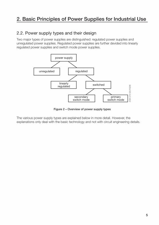
2.2. Power supply types and their designTwo major types of power supplies are distinguished: regulated power supplies and
unregulated power supplies. Regulated power supplies are further devided into linearly
regulated power supplies and switch mode power supplies.
2C
DC
27
2 0
23
F0
20
6
power supply
regulated
switchedlinearlyregulated
secondaryswitch mode
primaryswitch mode
unregulated
Figure 2 – Overview of power supply types
The various power supply types are explained below in more detail. However, the
explanations only deal with the basic technology and not with circuit engineering details.
2. Basic Principles of Power Supplies for Industrial Use

6
2.2.1 Unregulated power supplies
L
50/60 Hz
N
L+
L-
t t t t
U U U U
C
2C
DC
27
2 0
24
F0
b0
6
Figure 3 – Unregulated power supply
The AC mains voltage (50/60 Hz) applied at the input side is transformed to a lower level and
rectifi ed by a subsequent rectifi er. Then, a capacitor C smoothes the output voltage of the
rectifi er. The dimension of the transformer depends on the desired output voltage.
Due to the design of the electric circuit, the output voltage directly depends on the input volt-
age which in turn means that variations of the mains voltage have direct effect to the output
side. Since no regulation is done on the secondary side, the residual ripple of the output volt-
age is in the dimension of volts and specifi ed as a percentage of the DC output voltage.
Due to their simple design, unregulated power supplies are very robust and durable. Their
effi ciency is approx. 80 %.
Unregulated power supplies are primarily used for simple electromechanical applications that
do not require exact output voltages, e.g. for the supply of contactors.
Advantages Disadvantages
High effi ciency
Durable
Cost-effi cient
Large size
High residual ripple
No DC supply
2. Basic Principles of Power Supplies for Industrial Use
7
2.2.2 Linearly regulated power supplies
L
50/60 Hz
N
L+
L-
t
U U U
t t
C1 C2
T
Controller
2C
DC
27
2 0
25
F0
b0
6
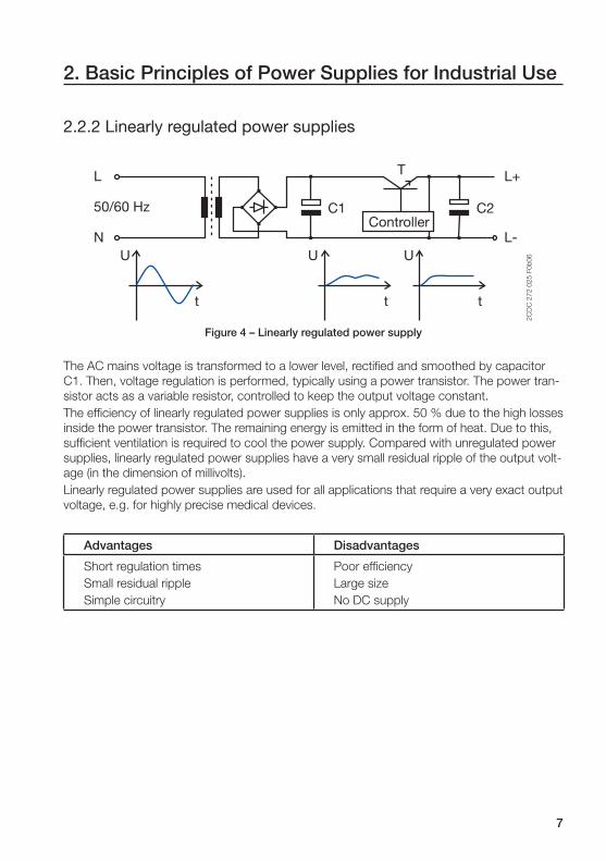
Figure 4 – Linearly regulated power supply
The AC mains voltage is transformed to a lower level, rectifi ed and smoothed by capacitor
C1. Then, voltage regulation is performed, typically using a power transistor. The power tran-
sistor acts as a variable resistor, controlled to keep the output voltage constant.
The effi ciency of linearly regulated power supplies is only approx. 50 % due to the high losses
inside the power transistor. The remaining energy is emitted in the form of heat. Due to this,
suffi cient ventilation is required to cool the power supply. Compared with unregulated power
supplies, linearly regulated power supplies have a very small residual ripple of the output volt-
age (in the dimension of millivolts).
Linearly regulated power supplies are used for all applications that require a very exact output
voltage, e.g. for highly precise medical devices.
Advantages Disadvantages
Short regulation times
Small residual ripple
Simple circuitry
Poor effi ciency
Large size
No DC supply
2. Basic Principles of Power Supplies for Industrial Use
8
2.2.3 Primary switch mode power supplies
L
50/60 Hz
N
C1
T
Controller Isolation
C2
L+
L-
t tt t t
U UU U U
2C
DC
27
2 0
26
F0
b0
6
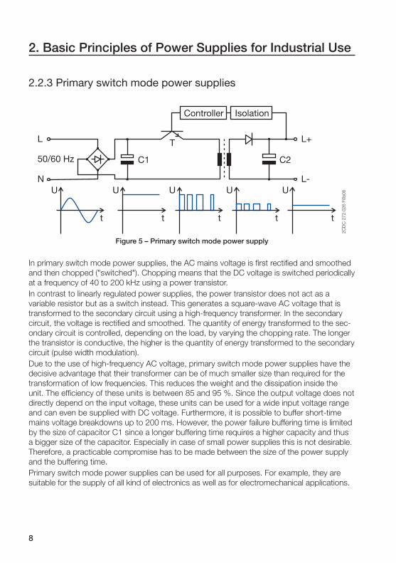
Figure 5 – Primary switch mode power supply
In primary switch mode power supplies, the AC mains voltage is fi rst rectifi ed and smoothed
and then chopped ("switched"). Chopping means that the DC voltage is switched periodically
at a frequency of 40 to 200 kHz using a power transistor.
In contrast to linearly regulated power supplies, the power transistor does not act as a
variable resistor but as a switch instead. This generates a square-wave AC voltage that is
transformed to the secondary circuit using a high-frequency transformer. In the secondary
circuit, the voltage is rectifi ed and smoothed. The quantity of energy transformed to the sec-
ondary circuit is controlled, depending on the load, by varying the chopping rate. The longer
the transistor is conductive, the higher is the quantity of energy transformed to the secondary
circuit ( pulse width modulation).
Due to the use of high-frequency AC voltage, primary switch mode power supplies have the
decisive advantage that their transformer can be of much smaller size than required for the
transformation of low frequencies. This reduces the weight and the dissipation inside the
unit. The effi ciency of these units is between 85 and 95 %. Since the output voltage does not
directly depend on the input voltage, these units can be used for a wide input voltage range
and can even be supplied with DC voltage. Furthermore, it is possible to buffer short-time
mains voltage breakdowns up to 200 ms. However, the power failure buffering time is limited
by the size of capacitor C1 since a longer buffering time requires a higher capacity and thus
a bigger size of the capacitor. Especially in case of small power supplies this is not desirable.
Therefore, a practicable compromise has to be made between the size of the power supply
and the buffering time.
Primary switch mode power supplies can be used for all purposes. For example, they are
suitable for the supply of all kind of electronics as well as for electromechanical applications.
2. Basic Principles of Power Supplies for Industrial Use

9
Advantages Disadvantages
Small size
Light weight
Wide input voltage range
Easy to regulate
High effi ciency
DC supply
Buffering in case of mains voltage
breakdown
Complex circuitry
Mains pollution
High frequency requires interference
suppression measures
Expensive
2.2.4 Secondary switch mode power suppliesThe design of secondary switch mode power supplies differs in only one detail from the de-
sign of primary switch mode power supplies. Chopping is performed on the secondary side.
As a result, a much bigger transformer has to be used since it has to transform the mains
voltage of 50/60 Hz. However, the transformer also acts as a fi lter and thus minimizes the
mains pollution.
Advantages Disadvantages
High effi ciency
Easy to regulate
Wide input voltage range
Low mains pollution
Large size
No DC supply
Expensive
2. Basic Principles of Power Supplies for Industrial Use

10
2.2.5 SummaryDuring the last years, primary switch mode power supplies became particularly accepted in
the fi eld of industrial applications. Their ability to accept almost any input voltage, their high
effi ciency and their compact design make these power supplies a fi rst class choice for the
engineering of new or the extension of existing installations.
The following table compares the different types of power supplies, taking into account their
most important characteristics.
Unregulated Linearly regulated Primary switch mode
Effi ciency + -- ++
Regulation time -- ++ +
Weight and size -- - ++
Residual ripple -- ++ +
Costs ++ - --
Fields of application -- + ++
Table 2 - Comparison of different power supply types
2. Basic Principles of Power Supplies for Industrial Use

11
2. Basic Principles of Power Supplies for Industrial Use
2.3. SafetyThe safety of persons and installation equipment is a major aspect even for power supplies.
The requirements to be fulfi lled in order to guarantee this safety are specifi ed by standardized
regulations. The most important terms from this fi eld are listed and explained below.
2.3.1 Electrical isolationElectrical isolation means that no current fl ow can occur from one electric circuit to a neigh-
boring other electric circuit.
In case of power supplies, this means that no electric connection exists between the input
side and the output side.
2.3.2 InsulationDifferent insulation types are defi ned in the standard IEC/EN 60950.
• Functional insulationInsulation necessary for the proper operation of the equipment.
• Basic insulationInsulation providing basic protection against electric shock.
• Supplementary insulationProtection against electric shock in the event of failure of the basic insulation.
• Double insulationInsulation comprising both basic insulation and supplementary insulation.
• Reinforced insulationA single insulation system which provides a degree of protection against electric shock
equivalent to double insulation.
2.3.3 Safe isolationSafe isolation according to EN 50178 is required for all interfaces between different electric
circuits, e.g. between an SELV circuit and a mains circuit.
Safe isolation means that no current fl ow can occur from one electric circuit to another. This
isolation has to be implemented either by double or reinforced insulation or by means of
protective shielding.
12
2. Basic Principles of Power Supplies for Industrial Use
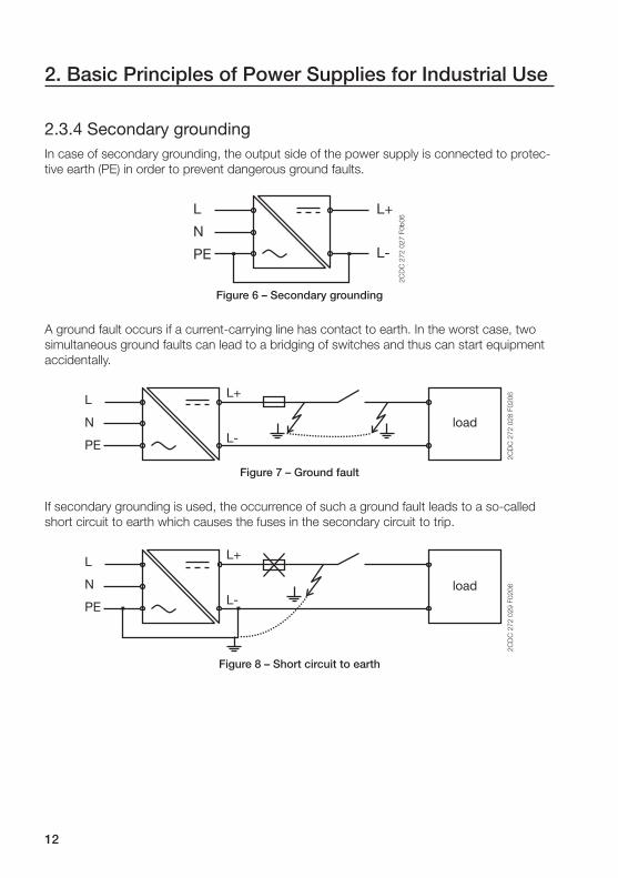
2.3.4 Secondary groundingIn case of secondary grounding, the output side of the power supply is connected to protec-
tive earth (PE) in order to prevent dangerous ground faults.
L
N
PE
L+
L-
2C
DC
27
2 0
27
F0
b0
6
Figure 6 – Secondary grounding
A ground fault occurs if a current-carrying line has contact to earth. In the worst case, two
simultaneous ground faults can lead to a bridging of switches and thus can start equipment
accidentally.
L
N
PE
L+
L-
2C
DC
27
2 0
28
F0
20
6
load
Figure 7 – Ground fault
If secondary grounding is used, the occurrence of such a ground fault leads to a so-called
short circuit to earth which causes the fuses in the secondary circuit to trip.
L
N
PE
L+
L-
2C
DC
27
2 0
29
F0
20
6load
Figure 8 – Short circuit to earth
13
2.3.5 SELVSELV according to IEC/EN 60950 is a safety extra low voltage. This voltage is so small that
no danger due to current fl owing through the human body can occur in case of direct con-
tact, neither during rated operation nor in case of a single fault. In case of power supplies,
this is achieved through electrical isolation and double or reinforced insulation between the
primary side and the secondary side. Grounding of the secondary side is not required but
permitted.
The peak value must not exceed 42.4 V in case of AC voltages and 60 V in case of DC volt-
ages. Lower voltages are defi ned for particular applications (e.g. toys).
2.3.6 PELVPELV according to IEC/EN 60950 is a protective extra low voltage. In case of PELV, the elec-
tric circuits are grounded and (like SELV) safely isolated from circuits of higher voltages. The
voltage limits are identical to SELV.
2. Basic Principles of Power Supplies for Industrial Use
14
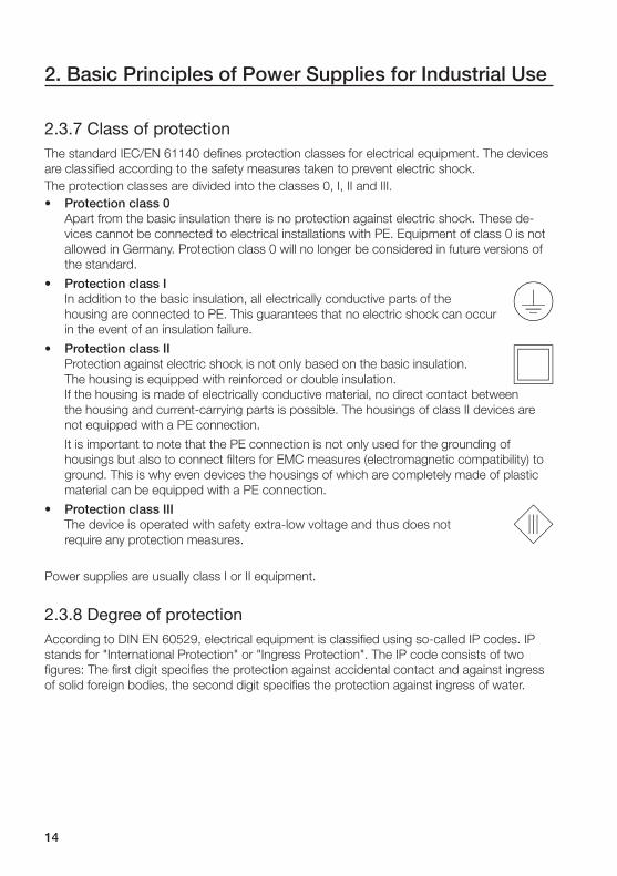
2.3.7 Class of protectionThe standard IEC/EN 61140 defi nes protection classes for electrical equipment. The devices
are classifi ed according to the safety measures taken to prevent electric shock.
The protection classes are divided into the classes 0, I, II and III.
• Protection class 0Apart from the basic insulation there is no protection against electric shock. These de-
vices cannot be connected to electrical installations with PE. Equipment of class 0 is not
allowed in Germany. Protection class 0 will no longer be considered in future versions of
the standard.
• Protection class IIn addition to the basic insulation, all electrically conductive parts of the
housing are connected to PE. This guarantees that no electric shock can occur
in the event of an insulation failure.
• Protection class IIProtection against electric shock is not only based on the basic insulation.
The housing is equipped with reinforced or double insulation.
If the housing is made of electrically conductive material, no direct contact between
the housing and current-carrying parts is possible. The housings of class II devices are
not equipped with a PE connection.
It is important to note that the PE connection is not only used for the grounding of
housings but also to connect fi lters for EMC measures (electromagnetic compatibility) to
ground. This is why even devices the housings of which are completely made of plastic
material can be equipped with a PE connection.
• Protection class IIIThe device is operated with safety extra-low voltage and thus does not
require any protection measures.
Power supplies are usually class I or II equipment.
2.3.8 Degree of protectionAccording to DIN EN 60529, electrical equipment is classifi ed using so-called IP codes. IP
stands for "International Protection" or "Ingress Protection". The IP code consists of two
fi gures: The fi rst digit specifi es the protection against accidental contact and against ingress
of solid foreign bodies, the second digit specifi es the protection against ingress of water.
2. Basic Principles of Power Supplies for Industrial Use

15
2. Basic Principles of Power Supplies for Industrial Use
Digit 1: Protection against accidental contact and ingress of solid foreign bodies
Digit Protection against accidental contact
Protection against ingress of solid foreign bodies
0 No protection No protection
1 Safe against touch of large body parts
(diameter: 50 mm)
Large solid foreign bodies
(diameter: > 50 mm)
2 Safe against fi nger touch
(diameter: 12 mm)
Medium-sized solid foreign bodies
(diameter: > 12.5 mm; length: < 80 mm)
3 Tools and wires
(diameter: > 2.5 mm)
Small solid foreign bodies
(diameter: > 2.5 mm)
4 Tools and wires
(diameter: > 1 mm)
Granular solid foreign bodies
(diameter: > 1 mm)
5(K) Completely safe against contact Deposit of dust
6(K) Completely safe against contact Ingress of dust
Table 3 – Degrees of protection against accidental contact and ingress of solid foreign bodies
Digit 2: Degrees of protection against ingress of water
Digit Protection against ingress of water
0 No protection
1 Protection against dripping water falling vertically
2 Protection against water drops falling up to 15° from the vertical
3 Protection against spray-water, sprayed at an angle of up to 60° either side of
the vertical
4 Protection against splash-water (against the housing from every direction)
4k Protection against splash-water at increased pressure (against the housing from
every direction), only applicable for road vehicles
5 Protection against jet-water
6 Protection against strong jet-water (conditions on ships deck)
6k Protection against strong jet-water at increased pressure (conditions on ships
deck), only applicable for road vehicles
7 Protection against the effects of temporary submersion in water
8 Protection against the effects of permanent submersion in water
9k Protection against water during high pressure/ steam cleaning,
only applicable for road vehicles
Table 4 – Degrees of protection against ingress of water
Power supplies usually are classifi ed with IP20. This is suffi cient for use in control cabinets.
16
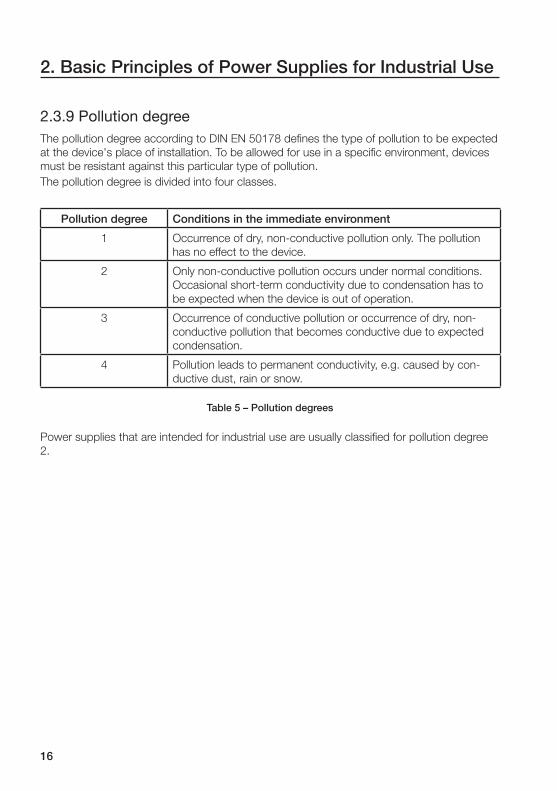
2.3.9 Pollution degreeThe pollution degree according to DIN EN 50178 defi nes the type of pollution to be expected
at the device's place of installation. To be allowed for use in a specifi c environment, devices
must be resistant against this particular type of pollution.
The pollution degree is divided into four classes.
Pollution degree Conditions in the immediate environment
1 Occurrence of dry, non-conductive pollution only. The pollution
has no effect to the device.
2 Only non-conductive pollution occurs under normal conditions.
Occasional short-term conductivity due to condensation has to
be expected when the device is out of operation.
3 Occurrence of conductive pollution or occurrence of dry, non-
conductive pollution that becomes conductive due to expected
condensation.
4 Pollution leads to permanent conductivity, e.g. caused by con-
ductive dust, rain or snow.
Table 5 – Pollution degrees
Power supplies that are intended for industrial use are usually classifi ed for pollution degree
2.
2. Basic Principles of Power Supplies for Industrial Use
17
2. Basic Principles of Power Supplies for Industrial Use
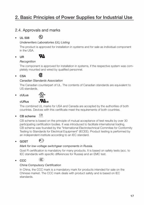
2.4. Approvals and marks
• UL 508 B Underwriters Laboratories (UL) Listing
The product is approved for installation in systems and for sale as individual component
in the USA.
• UR G Recognition
The component is approved for installation in systems, if the respective system was com-
pletely mounted and wired by qualifi ed personnel.
• CSA F Canadian Standards Association
The Canadian counterpart of UL. The contents of Canadian standards are equivalent to
US standards.
• cULus A cURus H The combined UL marks for USA and Canada are accepted by the authorities of both
countries. Devices with this certifi cate meet the requirements of both countries.
• CB scheme K CB scheme is based on the principle of mutual acceptance of test results by over 30
participating certifi cation bodies. It was introduced to facilitate international trading.
CB scheme was founded by the "International Electrotechnical Commitee for Conformity
Testing to Standards for Electrical Equipment" (IECEE). Product testing is performed by
an independent institute according to an IEC standard.
• GOST D Mark for low-voltage switchgear components in Russia.
Gost R certifi cation is mandatory for many products. It is based on safety tests (acc. to
IEC standards with specifi c differences for Russia) and an EMC test.
• CCC E China Compulsory Certifi cation
In China, the CCC mark is a mandatory mark for products intended for sale on the
Chinese market. The CCC mark deals with product safety and is based on IEC
standards.
18
2. Basic Principles of Power Supplies for Industrial Use
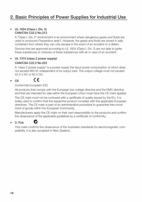
• UL 1604 (Class I, Div. 2) CAN/CSA C22.2 No.213
A "Class I, Div. 2" environment is an environment where dangerous gases and fl uids are
used or produced ("hazardous area"). However, the gases and fl uids are stored in safe
containers from where they can only escape in the event of an accident or a defect.
Devices that are approved according to UL 1604 (Class I, Div. 2) are not able to ignite
these substances or mixtures of these substances with air in case of an accident.
• UL 1310 (class 2 power supply)
CAN/CSA C22.2 No.223
A "class 2 power supply" is a power supply the input power consumption of which does
not exceed 660 W, independent of its output load. The output voltage must not exceed
42.4 V AC or 60 V DC.
• CE a Conformité Européen (CE)
All products that comply with the European low voltage directive and the EMC directive
and that are intended for sale within the European Union must have the CE mark applied.
The CE mark must not be confused with a certifi cate of quality issued by the EU. It is
solely used to confi rm that the respective product complies with the applicable European
directives. The CE mark is part of an administrative procedure to guarantee free move-
ment of goods within the European Community.
Manufacturers apply the CE mark on their own responsibility to the products and confi rm
the observance of the applicable guidelines by a certifi cate of conformity.
• C-Tick b This mark confi rms the observance of the Australian standards for electromagnetic com-
patibility. It is also accepted in New Zealand.

19
2. Basic Principles of Power Supplies for Industrial Use
2.5. StandardsStandards defi ne and regulate standardized terms, methods and systems.
The standardization of defi nitions has the following goals:
• Avoid misunderstanding in communication
• Guarantee the quality
• Cost reductions
• Enable the transfer of technology
• Support of cross-company and international cooperation
• Equal safety standards
The most important standards committee is the "International Electrotechnical Commission
(IEC)" based in Geneva. This committee consists of representatives of the member countries
representing the individual national electrotechnical interests.
Its European counterpart is the "European Committee for Electrotechnical Standardization"
(Comité Européen de Normalisation Electrotechnique, CENELEC).
The following table provides a brief overview of standards applicable for power supplies.
Product standard IEC/EN 61204 Low-voltage power supply units with DC
output
Low Voltage Directive 73/23/EEC Directive from 19 February 1973 of the
council of the European community for
meeting the requirements of the member
states regarding electrical equipment for
use within particular voltage limits
Electrical safety EN 50178 Electronic equipment for use in power
installations
UL 508 US safety standard for industrial control
systems, content similar to EN 50178
IEC/EN 60950 Information technology equipment – Safety
– Part 1: General requirements
UL 60950CSA 22.2
US version or Canadian version
of the standard IEC/EN 60950
EMC directive 89/336/EEC Directive from 3 May 1989 of the council of
the European community for meeting the
requirements of the member states regard-
ing the electromagnetic compatibility
20
2. Basic Principles of Power Supplies for Industrial Use
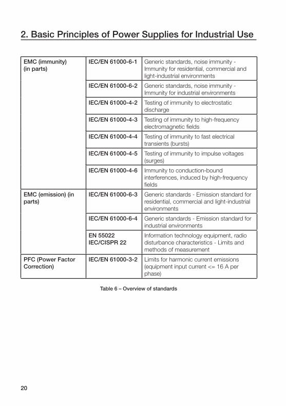
EMC (immunity)(in parts)
IEC/EN 61000-6-1 Generic standards, noise immunity -
Immunity for residential, commercial and
light-industrial environments
IEC/EN 61000-6-2 Generic standards, noise immunity -
Immunity for industrial environments
IEC/EN 61000-4-2 Testing of immunity to electrostatic
discharge
IEC/EN 61000-4-3 Testing of immunity to high-frequency
electromagnetic fi elds
IEC/EN 61000-4-4 Testing of immunity to fast electrical
transients (bursts)
IEC/EN 61000-4-5 Testing of immunity to impulse voltages
(surges)
IEC/EN 61000-4-6 Immunity to conduction-bound
interferences, induced by high-frequency
fi elds
EMC (emission) (in parts)
IEC/EN 61000-6-3 Generic standards - Emission standard for
residential, commercial and light-industrial
environments
IEC/EN 61000-6-4 Generic standards - Emission standard for
industrial environments
EN 55022IEC/CISPR 22
Information technology equipment, radio
disturbance characteristics - Limits and
methods of measurement
PFC (Power Factor Correction)
IEC/EN 61000-3-2 Limits for harmonic current emissions
(equipment input current <= 16 A per
phase)
Table 6 – Overview of standards

21
2. Basic Principles of Power Supplies for Industrial Use
2.6. Input voltage ranges
2.6.1 Wide range input Wide range input means that the device can be operated with any voltage within the speci-
fi ed limits. Therefore, many modern power supplies can be operated with AC voltages
between 85 and 264 V and DC voltages between 100 and 350 V without any loss of power,
i.e. the device is able to deliver the specifi ed rated power over the entire input voltage range.
Due to this technology, the devices are immune against mains voltage variations within these
limits.
Power supplies with wide range input can be connected to almost any power supply system
all over the world and thus can reduce costs for stock keeping and logistics since one variant
is able to cover almost all needs.
2.6.2 AutorangePower supplies that are equipped with autorange behavior perform an internal measurement
of the applied supply voltage and automatically switch between the available input voltage
ranges.
However, if the input voltage level is outside of the defi ned ranges, the autorange behavior
turns to a drawback since no reliable operation is possible in this case.
Power supplies with autorange input are often also described as wide-range devices by
mistake.
2.6.3 Manual range selectionIn case of manual range selection, the housing of the device is equipped with a selector
switch for manual input voltage range selection.
Usual switch settings are "110 V" and "230 V". When set to "110 V", the devices often can
be operated with AC voltages between 85 and 132 V. When set to "230 V", the devices
usually can be operated with AC voltages between 184 and 264 V and with DC voltages
between 220 and 350 V (refer to data sheet!).

22
2. Basic Principles of Power Supplies for Industrial Use
2.7. Protective functionsModern power supplies are equipped with various protective functions to protect the device
itself as well as the connected loads against damage.
2.7.1. Short-circuit and overload protection ( output characteristics)Various output characteristics are available for power supplies to provide electronic protec-
tion of the devices against damages due to overload or short circuit. The term overload
means that the current consumed by the loads exceeds the rated output current of the
power supply. A short circuit is a special form of an overload. In the event of a short circuit,
the output conductors of the power supply are connected to each other very low-resistively
and thus cause the output current to reach its maximum value, the so-called short circuit
current.
The output characteristic of a power supply is important for engineering. It plays a major role,
if it is required to start motors or other loads with high inrush currents, to perform a selective
switch-off of secondary branches, to bring an installation into a safe condition in case of an
overload or to switch off the power supply in case of a fault for reasons of process safety.
Fold-back characteristic / Hiccup mode
Power supplies usually are able to deliver a current of 1.1 times the rated current. They auto-
matically switch off, if the current consumption of the connected load exceeds this value or if
a short circuit occurs. After a defi ned period of time, the power supplies try to restart the load
and automatically switch off again, if the overload or the short circuit still exists. This proce-
dure repeats until the fault is cleared, i.e. the power supply will go into hiccup mode.
This mode is exclusively used for power supplies with low output power since there are sev-
eral drawbacks. For example, if the power supply has to start high loads (e.g. a motor), the
high inrush current will cause the power supply to go into hiccup mode. A further drawback
is that the power supply switches off very fast in case of a short circuit which makes second-
ary fusing very diffi cult.
Uout UoutIout
UN UN
IN
IN Iout t
2C
DC
27
2 0
30
F0
20
6
overload
1.1 x IN
1.1 x IN
Figure 9 – Hiccup mode

23
2. Basic Principles of Power Supplies for Industrial Use
U/I characteristic
Power supplies with a U/I characteristic perform current limiting to typically 1.1 to 1.2 times
the rated current at constant output voltage. This current is still available in case of an
overload or a short circuit. In this case, the power supply either immediately cuts the output
voltage to zero (rectangular current limiting) or performs slow lowering of the output voltage,
what, however, can possibly lead to a further increase of the output current (triangular current
limiting).
Since the current does not sag in case of an overload, this method enables reliable starting
of high loads.
Uout UoutIout
UN UN
IN
IN Iout t
2C
DC
27
2 0
31
F0
20
6
overload
1.1 x IN
1.1 x IN
Figure 10 – Rectangular current limiting
Uout UoutIout
UN UN
IN
IK
IN IoutIK t
2C
DC
27
2 0
32
F0
20
6
overload
1.1 x IN
1.1 x IN
Figure 11 – Triangular current limiting

24
2. Basic Principles of Power Supplies for Industrial Use
U/I characteristic with power reserves ( fold-forward)
Power supplies with a U/I characteristic and power reserves are able to deliver output cur-
rents of up to 1.5 times the specifi ed rated current at the rated output voltage. In addition to
this reserve, the power supply is able to manage a further output current increase of up to 50
%, however at decreasing output voltage (refer to "U/I characteristic"). The amount of current
reserves the power supply can deliver and how long it is able to deliver the reserves primarily
depends on the ambient temperature.
This method guarantees reliable starting even of very high loads. The high output current de-
livered in case of a short circuit makes secondary fusing easy. Therefore, this kind of power
supplies is particularly suitable for industrial use.
Uout UoutIout
UN UN
IN
IK
IN IoutIK t
2C
DC
27
2 0
33
F0
20
6
overload
IReserve
IReserve
Figure 12 – U/I characteristic with power reserves

25
2. Basic Principles of Power Supplies for Industrial Use
Effects of the ambient temperature to the output characteristic
The ambient temperature has direct effects to the maximum possible output power of a
power supply and thus also to its behavior in case of an overload or a short circuit.
The temperature inside of control cabinets can rise to more than 60 °C due to the waste heat
of the internal devices, solar irradiation or its place of installation. Power supplies must be
able to work reliably even under these high temperatures.
However, starting from a certain temperature value, the maximum available output power
will decrease depending on the temperature. The limit value starting from which this derating
process takes place, ranges from 40 °C to 60 °C, depending on the technical design and
the manufacturer of the power supply. The difference in temperature at which the derating
process starts is caused by the quality of the internal components.
The difference between the ambient temperature and the internal temperature of the power
supply is approximately 25 °C. As a result, no reserves will be available and the internal com-
ponents will be operated at their temperature maximum, if a manufacturer specifi es a maxi-
mum ambient temperature of 60 °C for a power supply the internal components of which
are specifi ed with a rated operating temperature of maximum 85 °C. ABB almost exclusively
uses components with a rated operating temperature of up to105 °C and guarantees proper
operation of their power supplies up to an ambient temperature of 70 °C resulting in a maxi-
mum internal temperature of approx. 95 °C. This increases the lifetime of our power supplies
since the components are not operated at their limits.
Pout [%] Pout [%]
100
75
60
0
100
75
60
0
-10 45 60 70 -10 45 60 70 2C
DC
27
2 0
34
F0
20
6
Ta [°C]Ta [°C]
Derating ABB Derating Competitor
Figure 13 – Derating diagrams
Depending on the device it is also possible that power supplies are not able to deliver their
full output power at very low ambient temperatures. This behavior is caused by an NTC
thermistor attached to the input circuits to limit the inrush current. In case of very low tem-
peratures, the resistance of this thermistor rises so high that the power supply is not able to
deliver its full output power.

26
2. Basic Principles of Power Supplies for Industrial Use
Example:Figure 14 shows the effects of the ambient temperature to the possibly available power re-
serves. At ambient temperatures below 40 °C, the power supply is able to deliver a continu-
ous current of 7.25 A with constant rated output voltage instead of its specifi ed rated current
of 5 A. Starting at a load of 7.25 A, the output voltage decreases continuously until the
maximum output current of 11 A is reached. When the ambient temperature is between 40
°C and 60 °C, the decrease of the output voltage already starts at a current of 5 A and again
ends at 11 A.
Uout [V]
Iout [A]
24
2C
DC
27
2 0
35
F0
20
6
Ta < 40 °CTa < 60 °C
5 7.25 11
Figure 14 – Derating example
Summary
Today, most power supplies for industrial use with output currents of approx. 5 A and higher
are equipped with a U/I output characteristic behavior. The advantage is clear: A constantly
high output current in case of overload or short circuit.
However, for increased requirements the U/I characteristic with power reserve gains more
and more acceptance due to its clear advantages.
The following table lists all available output characteristics with an assessment of their suit-
ability for different tasks.
Hiccup U/I U/I + reserve
Starting of motors - + ++
Tripping of fuses -- + ++
Tripping of circuit breakers -- o +
Table 7 – Comparison of output characteristics

27
2. Basic Principles of Power Supplies for Industrial Use
2.7.2. Thermal protectionWhen operating a power supply under extreme conditions for a long duration, e.g. in case
of permanent operation within the power limits or in case of very high ambient temperatures,
the power supply can heat up to a degree where safe operation is no longer guaranteed.
There are several methods to protect the power supply against damaging due to overtem-
perature.
• Reduction of the maximum output power to allow the power supply to cool down.
• The device is switched off completely and cannot resume operation until a manual reset
is performed. Depending on the manufacturer, the reset is done either using a corre-
sponding switch or by disconnecting the supply voltage.
• The device only switches off the output and does not switch it on until the temperature
falls below a certain limit value (refer to Figure 15).
This is the most frequently used method for modern power supplies.
Iout
IK
IN
Tt
t
2C
DC
27
2 0
36
F0
20
6
Short-circuit
TOff
TRestart
Ta
Figure 15 – Thermal switch-off

28
2. Basic Principles of Power Supplies for Industrial Use
2.7.3. Open-circuit protectionOpen-circuit protected power supplies do not require any minimum load to deliver a stable
output voltage. This is important e.g. for time-critical applications where a connected load
has to be supplied with voltage immediately. In case of power supplies that are not open-
circuit protected, it can last up to seconds until a connected load is actually supplied with
voltage.
2.7.4. Resistance to reverse feedThe resistance to reverse feed specifi es up to which voltage a power supply is immune
against the feeding of voltages into the secondary side.
Such a current fl ow can occur, if further voltage supplies are connected in parallel to the
power supply.
2.7.5. Overvoltage protection (secondary side)In case of an internal error of the power supply, this protection mechanism prevents the oc-
currence of overvoltage on the secondary side that could possibly damage or even destroy a
connected load or exceed the SELV voltage limit.
2.7.6. Power failure bufferingModern power supplies are able to maintain their output voltage for a certain time in case
of supply voltage dips. Usually, a power failure buffering time of at least 20 ms is aspired in
order to provide buffering for one complete cycle of the mains voltage.
29
2. Basic Principles of Power Supplies for Industrial Use
2.8. Fusing
2.8.1 Input fusingIf the power supply is equipped with an internal fuse, it is not necessary to protect the device
by an additional external fuse. If this internal fuse blows, the device can be considered as
defective.
However, the standards defi ne that it has to be possible to externally isolate power supplies
from the supplying mains. The use of circuit breakers on the primary side is particularly suit-
able for this purpose.
2.8.2 Output fusingAlmost all power supplies intended for industrial use are protected against overload and
short circuit by their internal electronics (refer to "Short-circuit and overload protection (output
characteristics)"). Therefore, if not explicitly stated, no additional fusing on the secondary side
is required for the purpose of device protection (refer to "Selectivity").
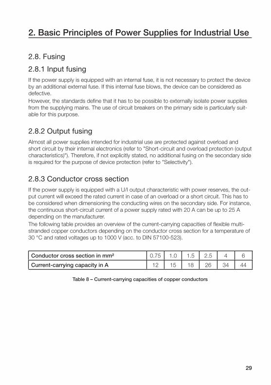
2.8.3 Conductor cross sectionIf the power supply is equipped with a U/I output characteristic with power reserves, the out-
put current will exceed the rated current in case of an overload or a short circuit. This has to
be considered when dimensioning the conducting wires on the secondary side. For instance,
the continuous short-circuit current of a power supply rated with 20 A can be up to 25 A
depending on the manufacturer.
The following table provides an overview of the current-carrying capacities of fl exible multi-
stranded copper conductors depending on the conductor cross section for a temperature of
30 °C and rated voltages up to 1000 V (acc. to DIN 57100-523).
Conductor cross section in mm² 0.75 1.0 1.5 2.5 4 6
Current-carrying capacity in A 12 15 18 26 34 44
Table 8 – Current-carrying capacities of copper conductors
30
2. Basic Principles of Power Supplies for Industrial Use
2.8.4 SelectivitySelectivity means the tripping coordination. In electrical systems, distinction can be made
between the "series selectivity" which means that individual fuses connected in series are
selective against each other and the "parallel selectivity" which means that electric circuits
connected in parallel are selective against each other.
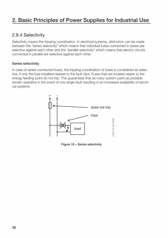
Series selectivity
In case of series-connected fuses, the tripping coordination of fuses is considered as selec-
tive, if only the fuse installed nearest to the fault trips. Fuses that are located nearer to the
energy feeding point do not trip. This guarantees that as many system parts as possible
remain operative in the event of one single fault resulting in an increased availability of electri-
cal systems.
+ -
2C
DC
27
2 0
37
F0
20
6
load
does not trip
trips
Figure 16 – Series selectivity

31
2. Basic Principles of Power Supplies for Industrial Use
Parallel selectivity
If one power supply is used to supply several loads, the occurrence of a short circuit at one
consumer will cause the power supply to enter its current limiting mode. This results in a
supply voltage dip at all connected load branches. To prevent this, the supply lines of the
individual load branches are equipped with fuses or circuit breakers. In order to guarantee
reliable isolation of the faulty load and to keep the remaining system operative in case of a
short circuit, the tripping time of the corresponding fuse or circuit breaker has to be suffi -
ciently short.
+ -
2C
DC
27
2 0
38
F0
20
6
load 1
operating
seperated
load 2
load 3
powersupply
Figure 17 – Parallel selectivity

32
2. Basic Principles of Power Supplies for Industrial Use
Tripping of fuses / circuit breakers
Tripping of fuses is always based on a thermal mechanism. In case of an overload, the con-
ductor inside the fuse heats and fi nally blows as a result. Depending on the type of fuse and
the amount of overload, the tripping time can range from milliseconds up to hours.
2 3 4 0.5 1 2 5
4
10-2
2
4
3 4 5 10 2 3 4 50 100 2 3 4 500 1000 2 3 4
10-1
2
4
10 0
2
4
10 1
2
4
10 2
2
4
10 3
2
4
10 4
0,16
0,25
0,5
0,6
1 2 4 6 8 10 12 16 20 25 32 40 50 63 80 100
125
Current intensity [A]
Blo
ww
-out
tim
e [s
]
Figure 18 – Tripping characteristic curve of a fuse (tripping time vs. current)
Circuit breakers are equipped with two tripping mechanisms, a thermal and a magnetic
mechanism.
Magnetic tripping is performed within milliseconds and typically caused by a short circuit. The
current required for magnetic tripping is a multiple of the rated current. Magnetic tripping can
also be caused by high overloads.
The thermal tripping mechanism of circuit breakers is similar to fuses but based on a bimetal
mechanism. The bimetal deforms depending on the current intensity and the duration of
current fl ow and thus trips the breaker latching mechanism which in turn disconnects the
electric circuit. The tripping times depend on the respective tripping characteristic and can
range from seconds to minutes.

33
2. Basic Principles of Power Supplies for Industrial Use
I1 = 1.13 x In I2 = 1.45 x In υR = 30 °C
Multiple of rated current [A]
Limiting curve from cold state
Rel
ease
tim
e
Min
utes
Sec
ond
s
Figure 19 – Tripping characteristic curve of a circuit breaker (tripping time vs. current, tripping characteristic "B")
Setting up a protection system with series selectivity using fuses and circuit breakers
Fuses are considered as selective if their rated currents differ clearly. The determination
whether particular fuses are selective against each other or not, can be done on the basis of
the tripping characteristic curves (tripping time vs. current). Fuses are considered as selec-
tive, if their characteristic curves do no touch or cross each other.
As an approximate general rule it can be assumed that fuses of the same rated characteristic
are selective, if the rated current of the fi rst fuse is at least 1.6 times the rated current of the
following fuse.
Since circuit breakers always perform magnetic tripping in case of a short circuit, circuit
breakers are only considered selective, if the following circuit breaker performs delayed trip-
ping in case of a short circuit (so-called "selective circuit breakers").

34
2. Basic Principles of Power Supplies for Industrial Use
Characteristic curves in case of a short circuit on the output side
An occurring short circuit (t1) causes a high short-time impulse current (I
P), the intensity of
which is multiple times the rated current (IN). This impulse current causes a fast thermal trip-
ping of fuses and a magnetic tripping of circuit breakers.
In power supplies, this impulse current is produced by the discharge of the capacitors on the
output side. After the capacitors are discharged (t2), the power supply delivers its continuous
short-circuit current (IK).
The area under the impulse current curve is called the heat of fusion (I²t) and represents the
tripping energy of fuses.
Since short circuits will never have an ideal connection resistance of zero, it is not possible to
give any general statement about the intensity of IP and its duration. This mainly depends on
the internal design of the power supply, the line resistances on the output side, the contact
resistances of the terminals, the ambient temperature and whether it is a high-resistance or a
low-resistance short circuit.
Iout
Uout [V]
24
IK
IP
Ri
RL
RL
RM
t1 t
t1
t1 - t2 = 500 μs - 5 ms
t2
I²t
t
IN
2C
DC
27
2 0
39
F0
20
6
loadpower supply
Figure 20 – Short-circuit behavior
35
2. Basic Principles of Power Supplies for Industrial Use
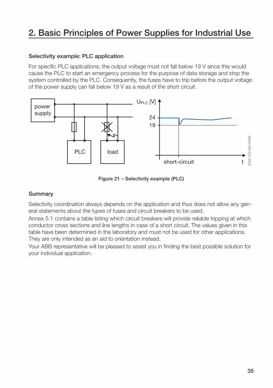
Selectivity example: PLC application
For specifi c PLC applications, the output voltage must not fall below 19 V since this would
cause the PLC to start an emergency process for the purpose of data storage and stop the
system controlled by the PLC. Consequently, the fuses have to trip before the output voltage
of the power supply can fall below 19 V as a result of the short circuit.
2419
t
2C
DC
27
2 0
40
F0
20
6
short-circuit
PLC load
power supply
UPLC [V]
Figure 21 – Selectivity example (PLC)
Summary
Selectivity coordination always depends on the application and thus does not allow any gen-
eral statements about the types of fuses and circuit breakers to be used.
Annex 5.1 contains a table listing which circuit breakers will provide reliable tripping at which
conductor cross sections and line lengths in case of a short circuit. The values given in this
table have been determined in the laboratory and must not be used for other applications.
They are only intended as an aid to orientation instead.
Your ABB representative will be pleased to assist you in fi nding the best possible solution for
your individual application.

36
2. Basic Principles of Power Supplies for Industrial Use
2.9. PFC (Power Factor Correction)Since 1 January 2001, the European standard regarding the limits for harmonic current emis-
sions (IEC/EN 61000-3-2) is in force. This standard defi nes the maximum allowed intensity of
harmonic currents fed back into the supplying mains system. It is applicable for consuming
devices with an active-power input between 75 and 100 W that are directly connected to the
public electricity supply.
Power supplies for industrial applications often do not require PFC, since large installations
are equipped with a central PFC, installed between the internal electric system and the public
electricity supply.
2.9.1 HarmonicsAll non-linear consuming devices, e.g. switch mode power supplies or rectifi ers with capaci-
tors, cause non-sinusoidal cyclic currents.
Iin
Uin
U, I
t
2C
DC
27
2 0
42
F0
b0
6
Figure 22 – Behavior of voltage and current
According to Fourier, each cyclic function can be separated into sinusoidal components.
Consequently, a non-sinusoidal current can be separated into several superimposed sinusoi-
dal currents the frequencies of which are integer multiples of the mains frequency. These so-
called harmonics are fed back into the supplying mains system where they can have negative
effects to the mains voltage and thus can cause malfunctioning of other sensitive consumers
supplied by the same mains. Harmonic currents furthermore increase the power consump-
tion of the power supplies since the energy of the harmonics ( reactive power) cannot be
utilized. This is why the supply lines have to be dimensioned with increased cross sections.
Minimizing the harmonic currents can be done using two methods:
- passive harmonic reduction (PFC) (� 2.9.2)
- active harmonic reduction (PFC) (� 2.9.3)

37
2. Basic Principles of Power Supplies for Industrial Use
2.9.2 Passive PFCFor passive PFC, a reactance coil is connected to the input circuit. This reactance coil buffers
energy from the mains and thus reduces the current pulses. The lower the pulses, the less
harmonics are produced.
The advantage of this solution is its easy implementation into existing circuitry, however, with
the drawback that it is not able to reduce all harmonics.
Iin
Uin
U, I
t
2C
DC
27
2 0
43
F0
b0
6
Figure 23 – Passive PFC
2.9.3 Active PFCActive PFC is able to deliver considerably better results. In a very simplifi ed consideration one
could say that the actual power supply is preceded by another power supply that performs a
regulation of the current consumption from the mains. This consumption is oriented towards
the sinusoidal supply voltage.
Using this technology, it is possible to avoid the production of almost every kind of harmon-
ics. However, the circuitry is much more complex than for passive PFC.
The ABB power supplies of the CP-C series are equipped with active PFC.
Iin
Uin
U, I
t
2C
DC
27
2 0
44
F0
b0
6
Figure 24 – Active PFC

38
3. ABB Product Range
3.1. Primary switch mode power suppliesIt is hard to imagine today's power engineering and industrial automation without modern
power supplies. ABB is a global partner in this fi eld and well prepared to fulfi ll these require-
ments with its new product range of switch mode power supplies.
Of course, all switch mode power supplies from ABB have been ecologically benefi cial, cost-
effective and equipped with primary switch mode technology for a long time. This is innova-
tive industrial electronics at the highest stage.
3.1.1 Product overview CP-E, CP-S and CP-CABB's product range of power supplies can be divided into three categories.
The power supplies of the CP-E series (E = "economy") are the ideal solution for basic ap-
plications without requirements for high currents.
The power supplies of the CP-S series (S = "standard") are desigend for higher currents and
represent a very economic solution due to their limited functionality.
The power supplies of the CP-C series (C = "comfort") cover the same output power range
as the devices of the CP-S series but provide additional functionality and can be expanded
by plug-in modules on the front side.
Features CP-E CP-S CP-C
Wide-range input • • (5 A version) •
Manual range selection -•
(10 A & 20 A version)-
Output voltage 5 V, 12 V, 24 V, 48 V 24 V
Adjustable output
voltage • - •
Output current 0.625-3 A 5 A, 10 A, 20 A
Effi ciency 75-90 % > 88 %
Overload behaviorU/I (fold-forward) /
hiccupU/I (fold-forward)
Temperature range -10...+70 °C -25...+70 °C
Derating above 60 °C
Parallel connection for
increased capacity- - •
Parallel connection for
redundancy• • •
PFC - - •
Table 9 – Overview of features for CP-E, CP-S, CP-C
39
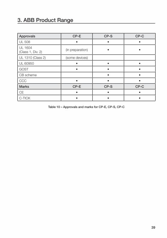
Approvals CP-E CP-S CP-C
UL 508 • • •
UL 1604
(Class 1, Div. 2)(in preparation) • •
UL 1310 (Class 2) (some devices)
UL 60950 • • •
GOST • • •
CB scheme • •
CCC • • •
Marks CP-E CP-S CP-C
CE • • •
C-TICK • • •
Table 10 – Approvals and marks for CP-E, CP-S, CP-C
3. ABB Product Range
40
2C
DC
27
1 0
15
F0
b0
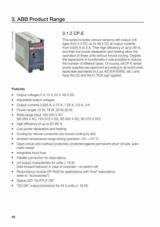
6 3.1.2 CP-EThis series includes various versions with output volt-
ages from 5 V DC up to 48 V DC at output currents
from 0.625 A to 3 A. Their high effi ciency of up to 89 %
and their low power dissipation and heating allow the
operation of these units without forced cooling. Despite
the expansions in functionality it was possible to reduce
the number of different types. Of course, all CP-E series
power supplies are approved according to all world-wide
applicable standards (cULus, IEC/EN 60950, etc.) and
have the CE and the C-TICK sign applied.
3. ABB Product Range
Features
• Output voltages 5 V, 12 V, 24 V, 48 V DC
• Adjustable output voltages
• Output currents 0.625 A, 0.75 A, 1.25 A, 2.5 A, 3 A
• Power ranges 15 W, 18 W, 30 W, 60 W
• Wide-range input 100-240 V AC
(90-265 V AC, 120-370 V DC, 85-264 V AC, 90-375 V DC)
• High effi ciency of up to 87-89 %
• Low power dissipation and heating
• Cooling by natural convection (no forced cooling by fan)
• Ambient temperature range during operation -25...+70 °C
• Open-circuit and overload protected, protected against permanent short circuits, auto-
matic restart
• Integrated input fuse
• Parallel connection for redundancy
• U/I output characteristic for units > 18 W
(fold-forward behavior in case of overload – no switch-off)
• Redundancy module CP-RUD for applications with "true" redundancy
(refer to "Accessories")
• Status LED "OUTPUT OK"
• "DC OK" output (transistor) for 24 V units (> 18 W)
41
2C
DC
27
1 0
61
F0
b0
4
3. ABB Product Range
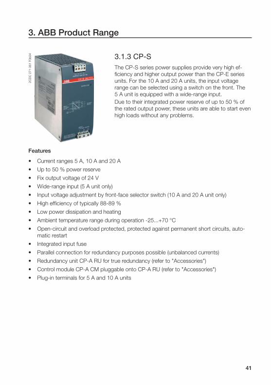
3.1.3 CP-SThe CP-S series power supplies provide very high ef-
fi ciency and higher output power than the CP-E series
units. For the 10 A and 20 A units, the input voltage
range can be selected using a switch on the front. The
5 A unit is equipped with a wide-range input.
Due to their integrated power reserve of up to 50 % of
the rated output power, these units are able to start even
high loads without any problems.
Features
• Current ranges 5 A, 10 A and 20 A
• Up to 50 % power reserve
• Fix output voltage of 24 V
• Wide-range input (5 A unit only)
• Input voltage adjustment by front-face selector switch (10 A and 20 A unit only)
• High effi ciency of typically 88-89 %
• Low power dissipation and heating
• Ambient temperature range during operation -25...+70 °C
• Open-circuit and overload protected, protected against permanent short circuits, auto-
matic restart
• Integrated input fuse
• Parallel connection for redundancy purposes possible (unbalanced currents)
• Redundancy unit CP-A RU for true redundancy (refer to "Accessories")
• Control module CP-A CM pluggable onto CP-A RU (refer to "Accessories")
• Plug-in terminals for 5 A and 10 A units

42
2C
DC
27
1 0
65
F0
b0
4
3. ABB Product Range
3.1.4 CP-CThe CP-C series power supplies provide extended
functionality compared to the CP-S series. The power
supplies can be further equipped with additional func-
tionality by means of the innovative concept of expansion
module slots on the front side. This saves space and
enables easy retrofi tting with an additional module since
no further wiring is required to connect the module to the
power supply.
The units are equipped with a wide-range input and thus
can be operated with all common mains voltages, even
in diffi cult environments with high supply voltage varia-
tions.
Like the CP-S series units, the CP-C series power sup-
plies provide internal power reserves enabling the start-
ing of high loads.
Features
• Current ranges 5 A, 10 A and 20 A
• Up to 50 % power reserve
• Adjustable output voltage from 22 to 28 V
• Wide-range input 85-264 V AC, 100-350 V DC
• High effi ciency of typically 88-89 %
• Low power dissipation and heating
• Ambient temperature range during operation -25...+70 °C
• Open-circuit and overload protected, protected against permanent short circuits, auto-
matic restart
• Integrated input fuse
• Parallel connection possible for increased capacity and/or redundancy purposes
(unbalanced currents)
• Redundancy unit CP-A RU for true redundancy (refer to "Accessories")
• Control module CP-A CM pluggable onto CP-A RU (refer to "Accessories")
• Messaging module CP-C MM (refer to "Accessories")
• Plug-in terminals for 5 A and 10 A units
• Status LED "OUTPUT OK"
• Power factor correction (PFC) according to EN 61000-3-2

43
3. ABB Product Range
3.1.5 CL-LAS.SD...The units of the CL-LAS.SD... range are power supplies
in so-called modular design.
The CL-LAS.SD001 provides two different output volt-
ages: 24 V and 12 V. The maximum output current is
0.25 A at 24 V and 20 mA at 12 V. The unit occupies a
space of 2 MW.
The CL-LAS.SD002 provides an output voltage of 24 V
and a maximum output current of 1.25 A. The unit oc-
cupies a space of 4 MW.
Features
• Current ranges 20 mA, 0.25 A, 1.25 A
• Output voltage 12 V, 24 V
• Wide-range input 85-264 V AC
• High effi ciency of typically > 87 %
• Open-circuit and overload protected, protected against permanent short circuits
• Hiccup mode
• Operating temperature range -25...+55 °C
• Integrated input fuse
• Status LED "POWER"
2C
DC
31
1 0
16
F0
b0
72
CD
C 3
11
01
6 F
0b
07

44
2C
DC
27
1 0
06
F0
b0
32
CD
C 2
71
08
7 F
0b
04
3. ABB Product Range
3.2. AccessoriesApart from the usual requirements made for power supplies, there is an increasing need par-
ticularly for features regarding the monitoring of systems. ABB is able to meet these require-
ments with a new module series for monitoring purposes.
3.2.1 Redundancy unit CP-RUD for CP-EThe redundancy unit CP-RUD can be used to provide
decoupling of two CP-E series power supplies for the
purpose of real redundancy.
The maximum output current is 5 A which allows the
connection of two power supplies with a current of 2.5 A
each or one 5 A power supply.
If one power supply fails, the decoupling provided by this
module prevents that this failure can affect the operation
of the second power supply.
3.2.2 Messaging module CP-C MM for CP-CThe messaging module is plugged to the front side of
CP-C series power supplies and thus enables the moni-
toring of this power supply.
The module is supplied with voltage by the power supply
itself and therefore does not require any further wiring for
voltage supply.
The "Remote off" input allows external remote controlled
switch on/off for the power supply.
The module performs monitoring of the input and output
voltages and indicates the present state by means of
LEDs and relays.
The relays operate according to the closed-circuit prin-
ciple which means that they are energized during normal
operation and de-energized in case of a fault. This allows
fault detection even in case of a total supply voltage loss.

45
2C
DC
27
1 0
10
F0
b0
62
CD
C 2
71
00
2 F
0b
05
3. ABB Product Range
3.2.3 Redundancy unit CP-A RU for CP-S/CThe redundancy unit for the CP-S/C series can be used
to provide decoupling of two power supply units in order
to set up a power supply system with real redundancy.
The maximum output current must not exceed 40 A.
This unit can be expanded by the control module
CP-A CM.
3.2.4 Control module CP-A CM for CP-A RUThis expansion module enables comfortable input volt-
age monitoring for the redundancy unit CP-A RU.
The threshold values for the output relays can be ad-
justed for each channel individually in the range of
14-28 V. The corresponding relay de-energizes, if the
voltage in one channel falls below the adjusted threshold
due to a fault (e.g. power supply failure, blown fuse). If
the corresponding voltage is above the adjusted thresh-
old value, the green LEDs "IN 1" and "IN 2" are on. The
green LED "OUT" is on, if the output voltage is > 3 V.
46
4. Applications
This chapter contains hints for engineering and practical application examples.
4.1. EngineeringThe questions to be answered when choosing a power supply are always the same. The
most frequently asked questions are listed below. The answers serve as decision making
aids in order to obtain best possible results for the respective application.
Most of the terms used below either have been discussed in chapter 2 or will be discussed in
the following sections.
• Which output voltage is required?
The following voltages are commonly used in industrial applications: 5 V, 12 V, 15 V, 24 V
and 48 V. Most applications require a supply voltage of 24 V.
• How much load is applied?
ABB power supplies are available for currents from 0.25 A up to 20 A. Therefore, suitable
power supplies of the required output current class are available for almost every applica-
tion without any need for oversizing.
• What kind of load is applied?
Particularly in case of diffi cult loads, e.g. motors or large contactors (refer to chapter 4.6
- "Supply for an AF185 contactor"), the power supply must provide suffi cient reserves in
order to be able to drive high inrush currents. All power supplies providing power re-
serves (e.g. CP-S/C series) are able to start such kinds of loads reliably without any need
for oversizing.
• Is it necessary to protect the installation against failure?
In case of increased requirements regarding the availability, it is recommended to set up a
redundant system. Using ABB’s decoupling modules and optional control modules, such
systems can be set up without problems.
For more detailed information, please refer to chapter "Parallel connection of power sup-
plies".

47
4. Applications
• Is it necessary to monitor the power supply?
If the power supply is installed in a remote control cabinet, it is recommended to equip it
with a messaging module in order to receive immediate notifi cation in case of a possible
failure.
This furthermore allows remote controlled switch-off for the power supply and thus ad-
ditionally enables it for use in inacccessible areas.
All power supplies of the CP-C series can be equipped with the messaging module
CP-C MM.
The 24 V power supplies > 18 W of the CP-E series are equipped with a "DC OK" signal-
ling output as a standard feature.
• What kind of protection against accidental contact is required?
The degree of protection of all ABB units is IP 20. This guarantees that there is no danger
when devices are touched with the fi ngers. IP 20 is suffi cient for use in control cabinets.
• What are the conditions in the supplying mains?
If large voltage variations are possible in the supplying mains, it is recommended to use
power supplies with a wide-range input since these units are able to deliver stable output
voltages even in case of input voltage variations.
The use of wide-range input power supplies is also recommended, if they are intended
for world-wide use. This will reduce costs since only one power supply type per power
class has to be kept in stock.
• Is PFC required?
Since 1 January 2001, all power supplies above 75 W, that can be directly connected to
the mains, must meet the limit values for harmonic currents according to IEC/EN 61000-
3-2.
However, PFC can also make sense when the power supply is not directly connected to
the public electricity supply, e.g. if the electric system contains consumers that are sensi-
tive to mains pollutions caused by the power supply.
All power supplies of the CP-C series are equipped with active PFC.

48
4. Applications
The following should be considered for the installation of power supplies:
• Dimensioning of lines and line protection devices
The supply lines have to be dimensioned suffi ciently according to all possible currents of
the application.
Please refer to the respective power supply data sheets for information about the current
loads in the supply lines of the power supply and the corresponding conductor cross
section recommendations.
On the output side it has to be considered that the output current in case of a short
circuit can amount to 1.5 times the rated output current.
It is recommended to use circuit breakers in order to allow external switch-off for the
power supplies. The tripping current of the circuit breakers has to be higher than the
expected input current.
• Mounting
The minimum clearances towards other devices (e.g. CP-S/C: 1 cm on each side, 8 cm
on top and bottom) and the installation instructions have to be observed in order to guar-
antee safe and reliable operation and to prevent excessive heating of the power supply.
All ABB power supplies are designed for DIN rail mounting. This allows quick and easy
mounting and removal.
• Ambient temperature
All CP series power supplies from ABB can be operated without any restrictions of the
output power up to an ambient temperature of 60 °C. From 60 °C to 70 °C, the maxi-
mum possible output power decreases steadily. Operation above 70 °C is not possible.
It has to be observed that the temperatures inside of control cabinets can be consider-
ably higher than outside of the cabinet, depending on the environment and the installed
components.
For more information about this, please refer to chapter "Effects of the ambient tempera-
ture to the output characteristic".

49
4. Applications
4.2. Output voltage adjustmentAll power supplies of the series CP-E and CP-C allow an adjustment of the output voltage.
The following subsections describe different applications that require an adjustment of the
output voltage.
4.2.1 Compensation of line lossesVoltage drops on the secondary lines can be compensated by adjusting the output voltage.
The following formula can be used to calculate the voltage drop on the lines:
�U =I � ρ � (2 � l)
A [1]
Where �U = voltage drop in [V]
I = current in [A]
ρ = resistivity (copper: � � m²
m0,0178 )
l = line length in [m] (multiplied by 2 to consider feeding and return wire)
A = conductor cross section in [mm²]
Example:
The power supply feeds a current of 10 A to a load that is connected by a cable with a length
of 5 m and a conductor cross section of 2.5 mm².
The voltage drop according to [1] is as follows:
�U = = 0,712 V2,5 m² � m
10 A � 0,0178 � � m² � (2 � 5 m)
The output voltage of the power supply has to be increased by this value in order to have the
rated voltage available at the load.

50
4. Applications
4.2.2 Balancing of power suppliesWhen used in parallel connection (refer to fi gure below), the power supplies must deliver
exactly the same output voltage. They require output voltage balancing.
Proceed as follows to balance the output voltages:
1) Adjust the desired output voltage at one power supply using a voltmeter
(e.g. to 24.0 V).
V
CP-C CP-C
24 V
+ - + -
2C
DC
27
2 0
45
F0
b0
6Figure 25 – Output voltage balancing of power supplies (1)
2) Then you have to measure the voltage difference between the power supplies. For
this purpose, connect the voltmeter to the plus terminals of both power supplies
and apply a direct wire connection between the minus terminals of the power sup-
plies. Then, adjust the output voltage of the second power supply until the voltmeter
displays a voltage difference of 0 V.
V
CP-C CP-C
0 V
+ - + -
2C
DC
27
2 0
46
F0
b0
6
Figure 26 – Output voltage balancing of power supplies (2)
The output voltage is now balanced and the power supplies can be used in parallel connec-
tion. For further details, please refer to the following chapter.
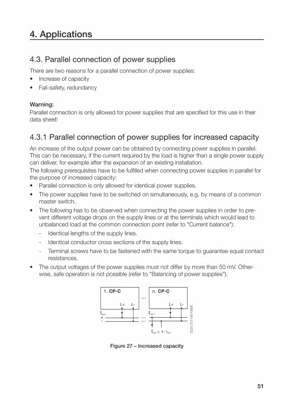
51
4. Applications
4.3. Parallel connection of power suppliesThere are two reasons for a parallel connection of power supplies:
• Increase of capacity
• Fail-safety, redundancy
Warning:Parallel connection is only allowed for power supplies that are specifi ed for this use in their
data sheet!
4.3.1 Parallel connection of power supplies for increased capacityAn increase of the output power can be obtained by connecting power supplies in parallel.
This can be necessary, if the current required by the load is higher than a single power supply
can deliver, for example after the expansion of an existing installation.
The following prerequisites have to be fulfi lled when connecting power supplies in parallel for
the purpose of increased capacity:
• Parallel connection is only allowed for identical power supplies.
• The power supplies have to be switched on simultaneously, e.g. by means of a common
master switch.
• The following has to be observed when connecting the power supplies in order to pre-
vent different voltage drops on the supply lines or at the terminals which would lead to
unbalanced load at the common connection point (refer to "Current balance"):
- Identical lengths of the supply lines.
- Identical conductor cross sections of the supply lines.
- Terminal screws have to be fastened with the same torque to guarantee equal contact
resistances.
• The output voltages of the power supplies must not differ by more than 50 mV. Other-
wise, safe operation is not possible (refer to "Balancing of power supplies").
CP-C1. n. CP-C
L+ L+ L- L-
2C
DC
272 0
53 F
0b
06
Figure 27 – Increased capacity

52
4. Applications
Important:The devices must not be connected directly to each other! This could lead to an overload of
the terminals since the terminals are dimensioned for the maximum output current of a single
power supply only. Always use a common connection point!
-+
-+ -+ -+ -+ -+ -+
3. CP-C2. CP-C1. CP-C
2C
DC
27
2 0
47
F0
20
6
load
Figure 28 – Incorrect wiring for increased capacity
-+ -+ -+ -+ -+ -+
+ -
1. CP-C 2. CP-C 3. CP-C
2C
DC
27
2 0
48
F0
20
6
load
Figure 29 – Correct wiring for increased capacity
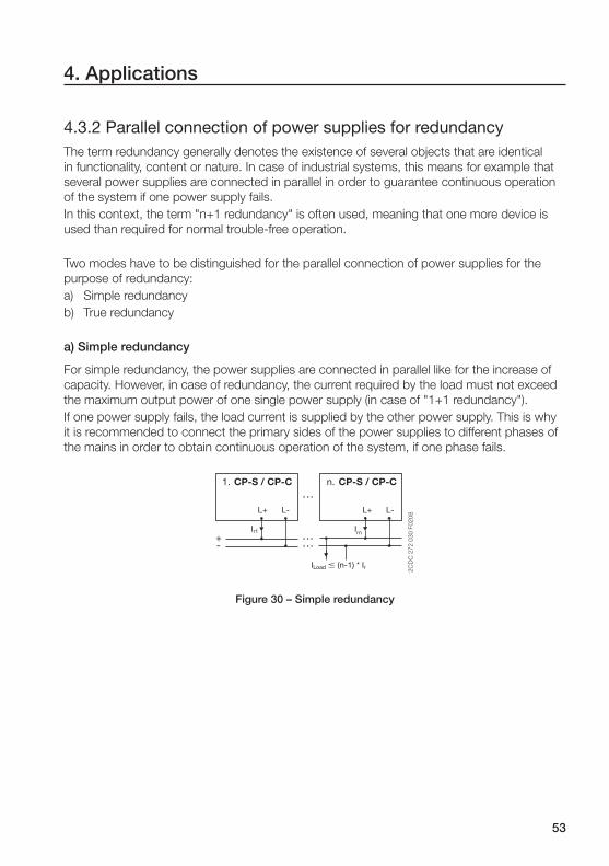
53
4. Applications
4.3.2 Parallel connection of power supplies for redundancyThe term redundancy generally denotes the existence of several objects that are identical
in functionality, content or nature. In case of industrial systems, this means for example that
several power supplies are connected in parallel in order to guarantee continuous operation
of the system if one power supply fails.
In this context, the term "n+1 redundancy" is often used, meaning that one more device is
used than required for normal trouble-free operation.
Two modes have to be distinguished for the parallel connection of power supplies for the
purpose of redundancy:
a) Simple redundancy
b) True redundancy
a) Simple redundancy
For simple redundancy, the power supplies are connected in parallel like for the increase of
capacity. However, in case of redundancy, the current required by the load must not exceed
the maximum output power of one single power supply (in case of "1+1 redundancy").
If one power supply fails, the load current is supplied by the other power supply. This is why
it is recommended to connect the primary sides of the power supplies to different phases of
the mains in order to obtain continuous operation of the system, if one phase fails.
CP-S / CP-C1. n. CP-S / CP-C
L+ L+ L- L-
Ir1 Irn
2C
DC
272 0
30 F
0208
ILoad � (n-1) * Ir
Figure 30 – Simple redundancy

54
4. Applications
b) True redundancy
For true redundancy it is necessary to provide decoupling of the individual power supplies.
Otherwise, the failed power supply could possibly act as a load for the other power supply
or, in the worst case, cause a short circuit on the secondary side resulting in a failure of the
second power supply.
Decoupling of the power supplies has to be performed by connecting decoupling diodes (so-
called O-ring diodes) to the secondary outputs. These diodes prevent mutual loading of the
power supplies in case of a fault and thus guarantee continuous supply.
For the setup of redundant power supply systems, ABB offers two redundancy units, the
CP-RUD (for output currents of up to 5 A) and the CP-A RU (for output currents of up to 40
A). The inputs of these units are connected to the terminals L+ and L- of the power supplies
(many other manufacturers often consider L+ only). The loads are supplied directly from the
outputs of the redundancy unit.
CP-S / CP-C CP-S / CP-C
L+ L+L- L-
CP-A RU
INPUT 1 INPUT 2+ + --
OUTPUT+ -+ -L N PE L N PE
L1L2L3NPE
Load
2C
DC
27
2 0
26
F0
20
5
Figure 31 – True redundancy using a CP-A RU

55
4. Applications
4.3.3 Current balanceCurrent balance means that all power supplies involved in a parallel connection deliver the
same share of the entire load current.
Balanced sharing of the current is of particular importance, if parallel connection is used
for the purpose of capacity increase. In case of unbalanced loading, the device bearing the
higher load would be exposed to increased aging and thus possibly fail prematurely. As a
result, the other power supplies involved in the parallel connection would become overloaded
resulting in a total failure of the entire installation.
Origination of current unbalances
Unbalanced sharing of the load currents can for example be caused by slightly different out-
put voltages of the involved units.
For example, if one power supply in a parallel connection delivers 24.3 V and the other
only 24.0 V, the higher voltage is also effective at the output of the power supply delivering
the lower voltage. In this case, the regulator of the power supply delivering only 24.0 V will
prevent the output of current. As a result, the unit delivering the higher voltage will supply
the entire load current until it enters its current limiting mode and, as a result, decreases its
output voltage (refer to "Short-circuit and overload protection (output characteristics)"). Since
the output voltage of the fi rst power supply has decreased now, the regulator of the second
power supply will allow the output of current and supply the remaining load current.
Iout [A]20 40
Uout [V]2
CD
C 2
72
04
9 F
02
06
overload
24.3
24.0
Figure 32 – Current unbalance
As a result, the fi rst power supply permanently operates in current limiting and is thus ex-
posed to considerably higher aging than the other power supply.
There are two basic approaches to obtain current balance:
a) Passive current balancing
b) Active current balancing

56
a) Passive current balancing
For passive current balancing, the output characteristics of the power supplies are changed
slightly: An increase of the current causes a slight decrease of the voltage. In parallel opera-
tion, this leads to a fi xed operating point.
Uout [V]
Iout [A]IN 2C
DC
27
2 0
50
F0
20
6
24.3
24.0
Figure 33 – Passive current balancing
Transferred to the example mentioned above, this has the following effect: At the beginning,
the power supply with the higher output voltage supplies the entire load current until its out-
put voltage (which is slowly decreased due to the increase of the current) reaches the rated
voltage of the other power supply. Then, the load current is supplied by both power supplies.
One disadvantage of this method is that the load is not shared equally to the power supplies.
The smaller the difference of the output voltages, the better the result. This is why manual
balancing of the output voltages is recommended. It is furthermore recommended to use
secondary lines of identical lengths and identical conductor cross sections.
b) Active current balancing
In case of active current balancing, the device is equipped with additional terminals to con-
nect the individual power supplies to each other. Via this connection, the power supplies
perform mutual regulation with the result that each power supply delivers exactly the same
current. A major advantage of this method is that no exact balancing of the output voltages is
required and that the output lines to the load can be of different lengths.
4. Applications
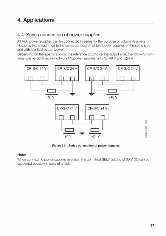
57
4. Applications
4.4. Series connection of power suppliesAll ABB power supplies can be connected in series for the purpose of voltage doubling.
However, this is restricted to the series connection of two power supplies of the same type
and with identical output power.
Depending on the specifi cation of the reference ground on the output side, the following volt-
ages can be obtained using two 24 V power supplies: +48 V, -48 V and �24 V.
+ - + - + - + -
+ -
+ -
CP-S/C 24 V CP-S/C 24 V
CP-S/C 24 V CP-S/C 24 V
CP-S/C 24 V CP-S/C 24 V
48 V -48 V
24 V -24 V 2C
DC
27
2 0
51
F0
b0
6Figure 34 – Series connection of power supplies
Note:
When connecting power supplies in series, the permitted SELV voltage of 60 V DC can be
exceeded possibly in case of a fault!

58
4. Applications
4.5. Monitoring functionsThe following sections describe the possible use of the ABB monitoring modules using vari-
ous example applications.
4.5.1 Monitoring of a single power supply using a CP-C with a CP-C MMAction in case of a fault: Output of a fault indication.
If both relays are de-energized, no supply voltage is available at the power supply or the
power supply is defective or switched off.
If the signaling relay for the "OUTPUT OK" indication is de-energized and the "INPUT OK"
relay is energized, either a short circuit exists on the secondary side that caused the power
supply to decrease its output voltage or the power supply itself is defective and thus not able
to supply any output voltage.
CP-C MM
+ - - +CP-C
L N PE
Load2
CD
C2
72
05
2F0
20
6
Relay messageOUTPUT OK
RemoteOFF
Relay messageINPUT OK
Figure 35 – CP-C with a CP-C MM
Remark: The messaging module is suitable for monitoring a single power supply! If power supplies
are connected in parallel, the redundancy unit CP-A RU has to be used together with the
monitoring module CP-A CM (refer to next subsection).

59
4. Applications
4.5.2 Monitoring of two power supplies using a CP-A RU with a CP-A CMAction in case of a fault: Output of a fault indication.
If both relays are de-energized, the voltages of both channels are below the adjusted thresh-
old value (e.g. 20 V). This could indicate that both power supplies failed or were switched off
or that an overload exists on the secondary side. A short-time de-energization of both relays
followed by the normal state with both relays energized could indicate that the connected
load has reached its normal operation again after a switch-on process. If only one relay de-
energizes, one power supply has possibly failed or has been switched off and, as a result,
redundancy is no longer given.
CP-S / CP-C CP-S / CP-C
L+ L+L- L-
CP-A CM
+ + --
+ -+ -
CP-A RU
Load
2C
DC
27
2 0
28
F0
20
5
Relay messagechannel 2 < 20 V
Relay messagechannel 1 < 20 V
Figure 36 – CP-A RU with a CP-A CM

60
4. Applications
4.5.3 Monitoring of one power supply using a CP-A RU with a CP-A CMAction in case of a fault: Switch-over to an alternative power supply.
The following application example shows the implementation of a switch-over functionality
to an alternative power supply (e.g. a battery) in the event of a fault in the monitored power
supply unit.
CP-S / CP-C
L+ L+ L- L-
CP-A CM
+ + - -
+ - + -
CP-A RU
L1 N PE
L N PE
Load
2C
DC
27
2 0
54
F0
20
6
Battery
Figure 37 – Application example: CP-A RU with a CP-A CM
A power supply and a battery are connected to a redundancy unit CP-A RU equipped with
a CP-A CM monitoring unit. During normal operation, the load connected to the redundancy
unit is supplied by the power supply unit. If the output voltage of the power supply unit drops
below the adjusted threshold value due to an internal fault or due to a supply voltage failure,
the monitoring module CP-A CM will recognize this and de-energize the corresponding relay.
This connects the battery to the redundancy unit. As a result, the power supply of the load
is provided by the battery. If the power supply unit returns to normal operation within the ad-
justed output voltage tolerances, the battery is disconnected from the redundancy unit again.
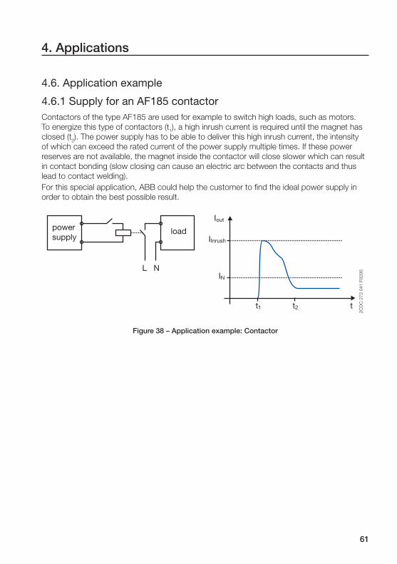
61
4. Applications
4.6. Application example
4.6.1 Supply for an AF185 contactorContactors of the type AF185 are used for example to switch high loads, such as motors.
To energize this type of contactors (t1), a high inrush current is required until the magnet has
closed (t2). The power supply has to be able to deliver this high inrush current, the intensity
of which can exceed the rated current of the power supply multiple times. If these power
reserves are not available, the magnet inside the contactor will close slower which can result
in contact bonding (slow closing can cause an electric arc between the contacts and thus
lead to contact welding).
For this special application, ABB could help the customer to fi nd the ideal power supply in
order to obtain the best possible result.
Iout
IN
t1 t2 t
L N
IInrush
2C
DC
27
2 0
41
F0
20
6
loadpowersupply
Figure 38 – Application example: Contactor

62
5. Appendix
5.1. Selectivity tables for section 2.8.4P
ow
er s
upp
lyC
P-S
24/
5.0
C
P-C
24/
5.0
Co
nduc
tor
cro
ss s
ectio
n0.
75 m
m²
1.0
mm
²1.
5 m
m²
2.5
mm
²
Tota
l len
gth
46
81
02
04
04
68
10
20
40
46
81
02
04
04
68
10
20
40
Leng
th [m
](b
oth
dire
ctio
ns)
2+ 2
3+ 3
4+ 4
5+ 5
10+
10
20+
20
2+ 2
3+ 3
4+ 4
5+ 5
10+
10
20+
20
2+ 2
3+ 3
4+ 4
5+ 5
10+
10
20+
20
2+ 2
3+ 3
4+ 4
5+ 5
10+
10
20+
20
Line
res
ista
nce
[m�
]9
61
44
19
22
40
48
09
60
72
10
81
44
18
03
60
72
04
87
29
61
20
24
04
80
28
42
56
70
14
02
80
Min
iatu
re c
ircui
t b
reak
ers
Z1
XX
XX
XX
XX
XX
XX
XX
XX
XX
XX
XX
XX
Z1.
6X
XX
XX
XX
XX
XX
XX
XX
XX
XX
XX
XX
X
Z2
XX
XX
XX
XX
XX
XX
XX
XX
XX
XX
XX
XX
Z3
XX
XX
XX
XX
XX
XX
XX
XX
XX
XX
XX
XX
Z4
XX
XX
XO
XX
XX
XX
XX
XX
XX
XX
XX
XX
Z6
XX
XX
XO
XX
XX
XO
XX
XX
XX
XX
XX
XX
Z8
XX
XX
OO
XX
XX
OO
XX
XX
XO
XX
XX
XX
B6
XO
OO
OO
XX
OO
OO
XX
XO
OO
XX
XX
OO
C1.
6X
OO
OO
OX
XO
OO
OX
XX
OO
OX
XX
XO
O
Leg
end
: x:
Circuit b
reaker
trip
s
o
: T
herm
al t
rip
pin
g o
f th
e c
ircuit b
reaker
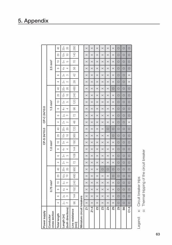
63
5. Appendix
Po
wer
sup
ply
CP
-S 2
4/10
.0
C
P-C
24/
10.0
Co
nduc
tor
cro
ss s
ectio
n0.
75 m
m²
1.0
mm
²1.
5 m
m²
2.5
mm
²
Tota
l len
gth
46
810
20
40
46
810
20
40
46
810
20
40
46
810
20
40
Leng
th [m
](b
oth
dire
ctio
ns)
2+ 2
3+ 3
4+ 4
5+ 5
10+
10
20+
20
2+ 2
3+ 3
4+ 4
5+ 5
10+
10
20+
20
2+ 2
3+ 3
4+ 4
5+ 5
10+
10
20+
20
2+ 2
3+ 3
4+ 4
5+ 5
10+
10
20+
20
Line
res
ista
nce
[m�
]9
61
44
19
22
40
48
09
60
72
10
81
44
18
03
60
72
04
87
29
61
20
24
04
80
28
42
56
70
14
02
80
Min
iatu
re c
ircui
t b
reak
ers
Z1
XX
XX
XX
XX
XX
XX
XX
XX
XX
XX
XX
XX
Z1.
6X
XX
XX
XX
XX
XX
XX
XX
XX
XX
XX
XX
X
Z2
XX
XX
XX
XX
XX
XX
XX
XX
XX
XX
XX
XX
Z3
XX
XX
XO
XX
XX
XX
XX
XX
XX
XX
XX
XX
Z4
XX
XX
XO
XX
XX
XO
XX
XX
XX
XX
XX
XX
Z6
XX
XX
OO
XX
XX
OO
XX
XX
XO
XX
XX
XX
Z8
OO
OO
OO
OO
OO
OO
OO
OO
OO
OO
OO
OO
B6
OO
OO
OO
OO
OO
OO
OO
OO
OO
OO
OO
OO
C1.
6O
OO
OO
OO
OO
OO
OX
OO
OO
OX
XO
OO
O
Leg
end
: x:
Circuit b
reaker
trip
s
o
: T
herm
al t
rip
pin
g o
f th
e c
ircuit b
reaker

64
5. Appendix
Po
wer
sup
ply
CP
-S 2
4/20
.0
C
P-C
24/
20.0
Co
nduc
tor
cro
ss s
ectio
n0.
75 m
m²
1.0
mm
²1.
5 m
m²
2.5
mm
²
Tota
l len
gth
46
810
20
40
46
810
20
40
46
810
20
40
46
810
20
40
Leng
th [m
](b
oth
dire
ctio
ns)
2+ 2
3+ 3
4+ 4
5+ 5
10+
10
20+
20
2+ 2
3+ 3
4+ 4
5+ 5
10+
10
20+
20
2+ 2
3+ 3
4+ 4
5+ 5
10+
10
20+
20
2+ 2
3+ 3
4+ 4
5+ 5
10+
10
20+
20
Line
res
ista
nce
[m�
]9
61
44
19
22
40
48
09
60
72
10
81
44
18
03
60
72
04
87
29
61
20
24
04
80
28
42
56
70
14
02
80
Min
iatu
re c
ircui
t b
reak
ers
Z1
XX
XX
XX
XX
XX
XX
XX
XX
XX
XX
XX
XX
Z1.
6X
XX
XX
XX
XX
XX
XX
XX
XX
XX
XX
XX
X
Z2
XX
XX
XX
XX
XX
XX
XX
XX
XX
XX
XX
XX
Z3
XX
XX
XX
XX
XX
XX
XX
XX
XX
XX
XX
XX
Z4
XX
XX
XX
XX
XX
XX
XX
XX
XX
XX
XX
XX
Z6
XX
XX
XX
XX
XX
XX
XX
XX
XX
XX
XX
XX
Z8
XX
XX
OO
XX
XX
OO
XX
XX
XO
XX
XX
XX
Z10
XX
XO
OO
XX
XX
OO
XX
XX
OO
XX
XX
XO
B6
XX
XX
OO
XX
XX
OO
XX
XX
XO
XX
XX
XX
C1.
6X
XX
XO
OX
XX
XO
OX
XX
XX
OX
XX
XX
X
Leg
end
: x:
Circuit b
reaker
trip
s
o
: T
herm
al t
rip
pin
g o
f th
e c
ircuit b
reaker

65
5. Appendix
5.2 List of fi guresFigure 1 – Simplifi ed consideration of the electrical design ................................. 4
Figure 2 – Overview of power supply types ........................................................ 5
Figure 3 – Unregulated power supply ................................................................ 6
Figure 4 – Linearly regulated power supply ........................................................ 7
Figure 5 – Primary switch mode power supply................................................... 8
Figure 6 – Secondary grounding ...................................................................... 12
Figure 7 – Ground fault .................................................................................... 12
Figure 8 – Short circuit to earth ....................................................................... 12
Figure 9 – Hiccup mode .................................................................................. 22
Figure 10 – Rectangular current limiting ........................................................... 23
Figure 11 – Triangular current limiting ............................................................... 23
Figure 12 – U/I characteristic with power reserves ........................................... 24
Figure 13 – Derating diagrams ......................................................................... 25
Figure 14 – Derating example .......................................................................... 26
Figure 15 – Thermal switch-off ........................................................................ 27
Figure 16 – Series selectivity ............................................................................ 30
Figure 17 – Parallel selectivity .......................................................................... 31
Figure 18 – Tripping characteristic curve of a fuse ........................................... 32
Figure 19 – Tripping characteristic curve of a circuit breaker (B characteristic) . 33
Figure 20 – Short-circuit behavior .................................................................... 34
Figure 21 – Selectivity example (PLC) .............................................................. 35
Figure 22 – Behavior of voltage and current ..................................................... 36
Figure 23 – Passive PFC ................................................................................. 37
Figure 24 – Active PFC .................................................................................... 37
Figure 25 – Output voltage balancing of power supplies (1) ............................. 50
Figure 26 – Output voltage balancing of power supplies (2) ............................. 50
Figure 27 – Increased capacity ........................................................................ 51
Figure 28 – Incorrect wiring for increased capacity .......................................... 52
Figure 29 – Correct wiring for increased capacity ............................................ 52
Figure 30 – Simple redundancy ....................................................................... 53
Figure 31 – True redundancy using a CP-A RU ................................................ 54
Figure 32 – Current unbalance ........................................................................ 55
Figure 33 – Passive current balancing ............................................................. 56
Figure 34 – Series connection of power supplies ............................................. 57
Figure 35 – CP-C with a CP-C MM ................................................................. 58
Figure 36 – CP-A RU with a CP-A CM ............................................................. 59
Figure 37 – Application example: CP-A RU with a CP-A CM ........................... 60
Figure 38 – Application example: Contactor .................................................... 61
66
5. Appendix
5.3 IndexA
Ambient temperature .........................25
Approvals ..........................................17
CB scheme ..................................17
CCC .............................................17
CSA .............................................17
CSA 22.2/213 ..............................18
cULus ..........................................17
cURus ..........................................17
GOST ...........................................17
UL 1310 (class 2 power supply) ...18
UL 1604 (Class I, Div. 2) ...............18
UL 508 ...................................17, 19
UR ...............................................17
Autorange ..........................................21
B
Balancing of power supplies ..............50
C
Class of protection .............................14
Protection class 0 .........................14
Protection class I ..........................14
Protection class II .........................14
Protection class III ........................14
Compensation of line losses ..............49
Conductor cross section ....................29
Current-carrying capacities ................29
Current balance .................................55
Current balancing ..............................56
Active current balancing ...............56
Passive current balancing .............56
Current limiting ...................................23
Rectangular current limiting ..........23
Triangular current limiting ..............23
D
Degree of protection ..........................14
Derating .................................25, 26, 38
E
Electrical design ...................................4
Electrical isolation ..............................11
EMC ..................................................20
Engineering ........................................46
F
Fold-back characteristic .....................22
Fold-forward characteristic .................24
Fuses .....................................30, 31, 32
Fusing ................................................29
Input fusing ..................................29
Output fusing ...............................29
G
Ground fault .......................................12
H
Harmonic reduction ...........................36
Harmonics .........................................36
Hiccup mode .....................................22
I
Increased capacity .............................51
Input side .............................................4
Insulation ...........................................11
Basic insulation ............................11
Double insulation ..........................11
Functional insulation .....................11
Reinforced insulation ....................11
Supplementary insulation .............11
IP code ..............................................14
M
Manual range selection ......................21
Marks ................................................17
C-Tick ..........................................18
CE ................................................18
Monitoring functions ..........................58
O
Open-circuit protection ......................28
Output characteristic ..............22, 25, 26
Output side ..........................................4
Overload protection ...........................22
Overvoltage protection .......................28
P
Parallel connection of power supplies 51
PELV ..................................................13
PFC (Power Factor Correction) ....20, 36
Active PFC ...................................37
Passive PFC .................................37
Pollution degree .................................16

67
5. Appendix
Power failure buffering ....................4, 28
Power supply types .............................5
Linearly regulated power supplies ...7
Primary switch mode power
supplies .........................................8
Secondary switch mode power
supplies .........................................9
Unregulated power supplies ...........6
Protection against accidental contact .....
....................................................14, 15
Protection against ingress of water ....15
Protective extra low voltage ...............13
Protective functions ...........................22
Pulse width modulation ........................8
R
Reactive power ..................................36
Redundancy ......................................53
Simple redundancy ......................53
True redundancy ..........................54
Resistance to reverse feed .................28
S
Safe isolation .....................................11
Safety ................................................11
Safety extra low voltage .....................13
Secondary grounding .........................12
Selectivity ...........................................30
Parallel selectivity .........................31
Series selectivity ...........................30
SELV ..................................................13
Series connection of power supplies ..57
Short-circuit protection ......................22
Standards ..........................................19
73/23/EEC (Low Voltage Directive) ...
....................................................19
89/336/EEC (EMC directive) .........19
DIN EN 60529 (IP code) ...............14
EN 50178 (Electrical isolation) ......11
EN 50178 (Electrical safety) ....16, 19
EN 55022 IEC/CISPR 22 (EMC) ...20
IEC/EN 60950 (Electrical safety) .......
........................................11, 13, 19
IEC/EN 61000-3-2 (PFC) ..............20
IEC/EN 61000-4-... (EMC) ............20
IEC/EN 61000-6-... (EMC) ............20
IEC/EN 61140 (Class of protection) ..
....................................................14
IEC/EN 61204 (Product standard) 19
T
Thermal protection .............................27
U
U/I characteristic ................................23
U/I characteristic with power reserve ..24
W
Wide-range input ...............................21

Pub
lication N
o. 2
CD
C 1
14 0
48 M
0202 (01/0
9)
Printe
d in
the F
ed
era
l Rep
ub
lic o
f G
erm
any
ABB STOTZ-KONTAKT GmbH
Export Department
Eppelheimer Straße 82
69123 Heidelberg
Germany
www.abb.com/lowvoltage � Control Products � Power Supplies