Course Outcome CL · · 2018-02-05To Studythe essentiality of balancing. 5. ... rotating in the...
17
1 Directorate Of Technical Education Karnataka StateMECH 15ME32T Government of Karnataka Department of Technical Education Board of Technical Examinations, Bangalore Prerequisites: Knowledge of basic mathematics and Applied Science, Engineering Graphics Course Objectives: 1. To provide basic concept of kinematics and kinetics of machine elements. 2. To study basics of power transmission. 3. To study the effect of friction. 4. To Study the essentiality of balancing. 5. To acquaint with working principles of CAM Mechanism. 6. To study the different types of vibration and to understand critical speed of shaft Course Outcomes: On successful completion of the course, the students will be able to attain CO: Course Outcome CL Linked PO Teaching Hrs CO1 Analyze and Apply the knowledge of these machines, mechanisms and related terminologies in mechanical engineering science in maintaining sustainable environment and its impact on society R/U/A/A n 1,2,3,4,5,6 10 10 CO2 Select appropriate power transmission mechanisms R/U/A 1,2,3,4,5,6 10 11 CO3 Analyze the effect of friction on machine elements U/A/An 1,2,3,4,5,6, 10 10 CO4 Appreciate the essentiality of balancing in Rotating Parts.. U/A 1,2,3,4,5,6 10 07 CO5 Construct CAM profile for the specific follower motion R/U/A 1,2,3,4,5,6 10 10 CO6 Understand the Terminology and types associated with vibration in machine elements R/U 1,2, 10 04 Total sessions 52 Legend: R; Remember, U: Understand A: Application Course Title: MECHANICS OF MACHINES Scheme (L:T:P) : 4:0:0 Total Contact Hours: 52 Course Code: 15ME32T Type of Course: Lectures, Self Study & Quiz Credit :04 Core/ Elective: Core CIE- 25 Marks SEE- 100 Marks
Transcript of Course Outcome CL · · 2018-02-05To Studythe essentiality of balancing. 5. ... rotating in the...
1
Directorate Of Technical Education Karnataka StateMECH 15ME32T
Government of KarnatakaDepartment of Technical Education
Board of Technical Examinations, Bangalore
Prerequisites: Knowledge of basic mathematics and Applied Science, Engineering Graphics
Course Objectives:
1. To provide basic concept of kinematics and kinetics of machine elements.2. To study basics of power transmission.3. To study the effect of friction.4. To Study the essentiality of balancing.5. To acquaint with working principles of CAM Mechanism. 6. To study the different types of vibration and to understand critical speed of shaft
Course Outcomes:
On successful completion of the course, the students will be able to attain CO:
Course Outcome CL Linked PO
Teaching Hrs
CO1
Analyze and Apply the knowledge ofthese machines, mechanisms and related terminologies in mechanical engineering science in maintaining sustainable environment and its impact on society
R/U/A/An
1,2,3,4,5,610
10
CO2Select appropriate power transmission mechanisms R/U/A
1,2,3,4,5,610
11
CO3
Analyze the effect of friction on machine elements U/A/An
1,2,3,4,5,6,10 10
CO4
Appreciate the essentiality of balancing in Rotating Parts..
U/A1,2,3,4,5,6
10
07
CO5 Construct CAM profile for the specific follower motion
R/U/A 1,2,3,4,5,610
10
CO6 Understand the Terminology and types associated with vibration in machine elements
R/U 1,2, 10 04
Total sessions 52Legend: R; Remember, U: Understand A: Application
Course Title: MECHANICS OF MACHINES
Scheme (L:T:P) : 4:0:0 Total Contact Hours: 52Course Code:15ME32T
Type of Course: Lectures, Self Study & Quiz
Credit :04Core/ Elective:
Core
CIE- 25 Marks SEE- 100 Marks
2
Directorate Of Technical Education Karnataka StateMECH 15ME32T
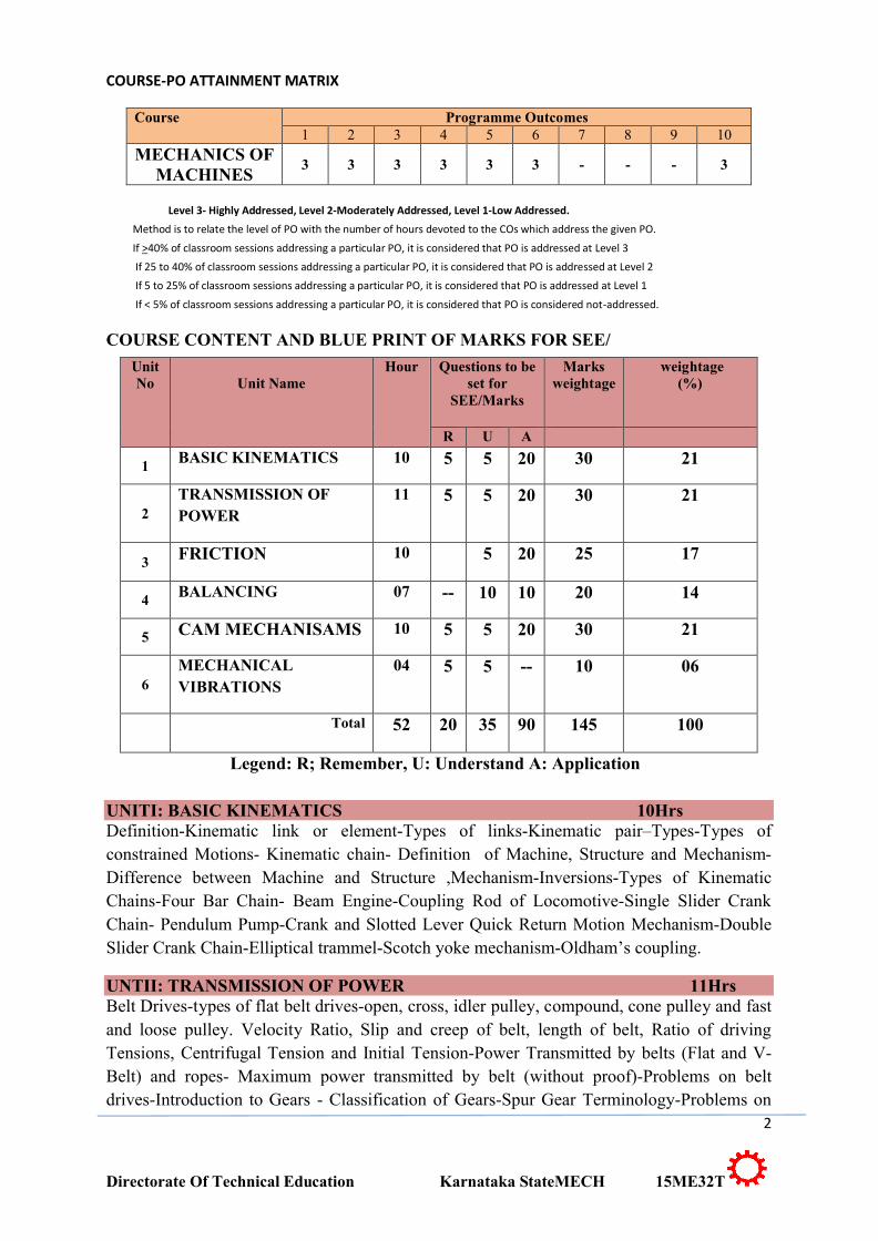
COURSE-PO ATTAINMENT MATRIX
Course Programme Outcomes1 2 3 4 5 6 7 8 9 10
MECHANICS OF MACHINES
3 3 3 3 3 3 - - - 3
Level 3- Highly Addressed, Level 2-Moderately Addressed, Level 1-Low Addressed.
Method is to relate the level of PO with the number of hours devoted to the COs which address the given PO.
If >40% of classroom sessions addressing a particular PO, it is considered that PO is addressed at Level 3
If 25 to 40% of classroom sessions addressing a particular PO, it is considered that PO is addressed at Level 2
If 5 to 25% of classroom sessions addressing a particular PO, it is considered that PO is addressed at Level 1
If < 5% of classroom sessions addressing a particular PO, it is considered that PO is considered not-addressed.
COURSE CONTENT AND BLUE PRINT OF MARKS FOR SEE/
UnitNo Unit Name
Hour Questions to be set for
SEE/Marks
Marksweightage
weightage(%)
R U A
1BASIC KINEMATICS 10 5 5 20 30 21
2TRANSMISSION OF POWER
11 5 5 20 30 21
3 FRICTION 10 5 20 25 17
4BALANCING 07 -- 10 10 20 14
5 CAM MECHANISAMS 10 5 5 20 30 21
6MECHANICAL VIBRATIONS
04 5 5 -- 10 06
Total 52 20 35 90 145 100
Legend: R; Remember, U: Understand A: Application
UNITI: BASIC KINEMATICS 10HrsDefinition-Kinematic link or element-Types of links-Kinematic pair–Types-Types of constrained Motions- Kinematic chain- Definition of Machine, Structure and Mechanism-Difference between Machine and Structure ,Mechanism-Inversions-Types of Kinematic Chains-Four Bar Chain- Beam Engine-Coupling Rod of Locomotive-Single Slider Crank Chain- Pendulum Pump-Crank and Slotted Lever Quick Return Motion Mechanism-Double Slider Crank Chain-Elliptical trammel-Scotch yoke mechanism-Oldham’s coupling.
UNTII: TRANSMISSION OF POWER 11HrsBelt Drives-types of flat belt drives-open, cross, idler pulley, compound, cone pulley and fast and loose pulley. Velocity Ratio, Slip and creep of belt, length of belt, Ratio of driving Tensions, Centrifugal Tension and Initial Tension-Power Transmitted by belts (Flat and V-Belt) and ropes- Maximum power transmitted by belt (without proof)-Problems on belt drives-Introduction to Gears - Classification of Gears-Spur Gear Terminology-Problems on
3
Directorate Of Technical Education Karnataka StateMECH 15ME32T
gears –(centre distance only) Introduction to Gear Trains-Types of Gear trains –Simple, Compound, Reverted and Epicyclic gear trains- Problems on Gear Trains
UNITIII: FRICTION 10Hrs
Friction-Introduction-Types of Friction, Laws of solid friction, coefficient of friction, limiting angle of friction, angle of Repose -Friction in Journal Bearing-Power Transmission in the Journal bearing-Friction in Thrust Bearing-Pivot Bearing– Flat and Conical bearing-Collar Bearing –Problems on bearings (Assuming uniform pressure theory)- Friction in Clutches-Single Disc Clutch- Multiple Disc Clutch- Problems on clutches (Assuming uniform wear theory)-Introduction to Brakes-Internal Expanding Brake (Mechanical & Hydraulic).
UNIT IV:BALANCING 07 HrsIntroduction-Static and Dynamic balancing-Balancing of single rotating massby a single mass rotating in the same plane -Balancing of several masses rotating in the same plane-Problems on above (Analytical and Graphical methods).
UNIT V: CAM MECHANISAMS 10HrsCams-Introduction-Classification of followers and cams-Terminology of cam- Displacement diagram for the following Motion of follower-Uniform velocity -Simple Harmonic Motion (SHM)-Uniform Acceleration and Retardation Motion (UARM),Cam profile construction for Knife edge follower and Roller follower.
UNIT VI: MECHANICAL VIBRATIONS 04Hrs
Introduction- Terms used in Vibrations-Types of Vibrations-Free Vibrations- Forced Vibrations-Damped Vibrations-Types of Free Vibrations- Longitudinal, Transverse and Torsional- Critical or Whirling speed of a shaft.
®TEXT BOOKS
1. Rattan.S.S, “Theory of Machines”, Tata McGraw -Hill Publishers, New Delhi, 2009.2. Khurmi R S, Guptha J.K “Theory of machines ”, 5 Edition, S.Chand and company ,Delhi ISBN 81-219-2524-X
REFERENCES1. Thomas Bevan, “Theory of Machines”, CBS Publishers and Distributors, 3rd Edition, 2005.2. Ramamurti,V., “Mechanism and Machine Theory”, 2nd Edition, Narosa Publishing House,2005.3. Ghosh.A and A.K.Mallick, “Theory of Mechanisms and Machines”, Affiliated East- WestPrivate Limited, New Delhi, 1998.4. Rao.J.S and Dukkipati R.V, “Mechanism and Machine Theory”, Wiley-Eastern Limited,New Delhi, 1992.
4
Directorate Of Technical Education Karnataka StateMECH 15ME32T
LIST OF SOFTWARES/ LEARNING WEBSITES: 1. http://nptel.iitm.ac.in/video.php?subjectId=112104121
2. http://www.technologystudent.com/gears1/gears7.htm
3. http://kmoddl.library.cornell.edu/model.php?m=20http://www3.ul.ie/~kirwanp/whatisacamandfollowersyste.htm
4. http://nptel.iitm.ac.in/courses/Webcourse-contents/IIT-Delhi/Kinematics%20of%20Machine/index.htm
5. http://elearning.vtu.ac.in/12/enotes/Des_Mac-Ele2/Unit6-RK.pdf
6. www.tecquipment.com/Theory_of_Machines.aspx
7. www.researchgate.net/.../0094-114X_Mechanism_and_Machine_Theory
8. www.journals.elsevier.com/mechanism-and-machine-theory/
9. www.iftomm.org/
10. www.wiziq.com/online-tests/44047-mechanical-theory-of-machine
11. www.cs.ubc.ca/~murphyk/Teaching/CS340-Fall07/infoTheory.pdf
SUGGESTED LIST OF STUDENT ACTIVITYSNote: the following activities or similar activities for assessing CIE (IA) for 5 marks (Any one)
∑ Each student should do any one of the following type activity or similar activity related to the course and before take up, get it approved from concerned Teacher and HOD.
∑ Each student should conduct different activity and no repeating should occur
1 List the mechanisms which you are using in your day to day life. Sketch any three from these. Study and submit handwritten report of 500 words
2 Take a photo of a actual kinematic mechanism used in an automobile, study and submit handwritten report of 500 words
3 Analyse the effect of friction in real situation and submit handwritten report of 500 words
2 List the mechanism used in a typical car. study and submit handwritten report of 500 words
3 Identify and measure the dimensions of Flywheel used in automobile. study and submit handwritten report of 500 words
4 Identify the type of clutches and cams used in different automobiles and also the type of brakes in automobile and bicycle. study and submit handwritten report of 500 words
5 Visit the market and collect the data of items which are used in any mechanisms. Data includes specifications, cost, applications, etc. Also name the mechanism/s in which such item/s is/are use .Study and submit handwritten report of 500 words
Course Delivery∑ The course will be delivered through lectures and Power point presentations/ Video∑ Teachers can prepare or download PPT of different topics on Mechanisms usage in
mechanical engineering application.
∑ Motivate student to take case study on kinematics, power transmission and to inculcate him for self and continuous learning.
5
Directorate Of Technical Education Karnataka StateMECH 15ME32T
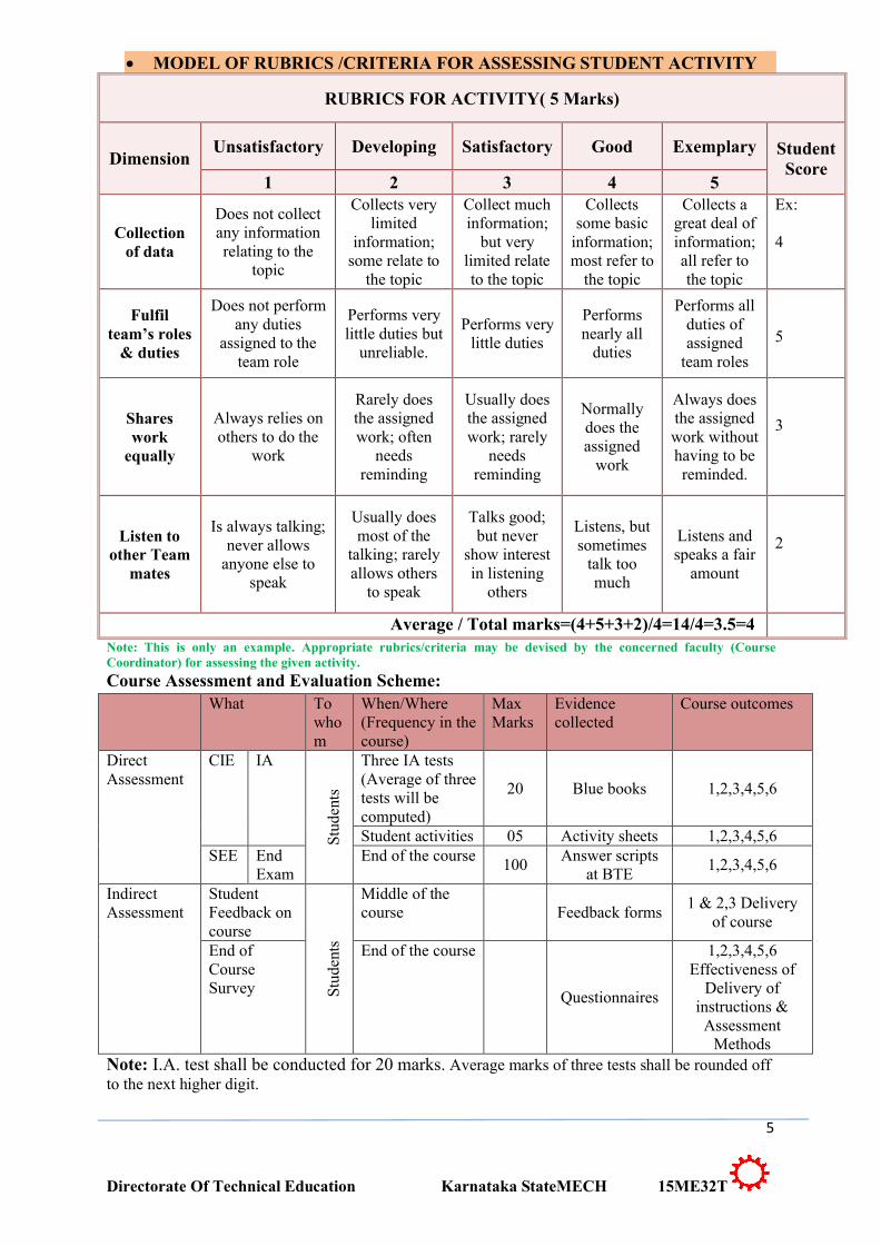
∑ MODEL OF RUBRICS /CRITERIA FOR ASSESSING STUDENT ACTIVITY
RUBRICS FOR ACTIVITY( 5 Marks)
DimensionUnsatisfactory Developing Satisfactory Good Exemplary Student
Score1 2 3 4 5
Collection of data
Does not collect any information relating to the
topic
Collects very limited
information; some relate to
the topic
Collect much information;
but very limited relate to the topic
Collects some basic
information; most refer to
the topic
Collects a great deal of information; all refer to the topic
Ex:
4
Fulfil team’s roles
& duties
Does not perform any duties
assigned to the team role
Performs very little duties but
unreliable.
Performs very little duties
Performs nearly all
duties
Performs all duties of assigned
team roles
5
Shares work
equally
Always relies on others to do the
work
Rarely does the assigned work; often
needs reminding
Usually does the assigned work; rarely
needs reminding
Normally does the assigned
work
Always does the assigned work without having to be reminded.
3
Listen to other Team
mates
Is always talking; never allows
anyone else to speak
Usually does most of the
talking; rarely allows others
to speak
Talks good; but never
show interest in listening
others
Listens, but sometimes
talk too much
Listens and speaks a fair
amount
2
Average / Total marks=(4+5+3+2)/4=14/4=3.5=4Note: This is only an example. Appropriate rubrics/criteria may be devised by the concerned faculty (Course Coordinator) for assessing the given activity.
Course Assessment and Evaluation Scheme:What To
whom
When/Where(Frequency in the course)
Max Marks
Evidence collected
Course outcomes
Direct Assessment
CIE IA Three IA tests(Average of three tests will be computed)
20 Blue books 1,2,3,4,5,6
Student activities 05 Activity sheets 1,2,3,4,5,6SEE End
ExamEnd of the course
100Answer scripts
at BTE1,2,3,4,5,6
Indirect Assessment
Student Feedback on course
Middle of the course Feedback forms
1 & 2,3 Delivery of course
End of Course Survey
End of the course
Questionnaires
1,2,3,4,5,6Effectiveness of
Delivery of instructions & Assessment
MethodsNote: I.A. test shall be conducted for 20 marks. Average marks of three tests shall be rounded off to the next higher digit.
6
Directorate Of Technical Education Karnataka StateMECH 15ME32T
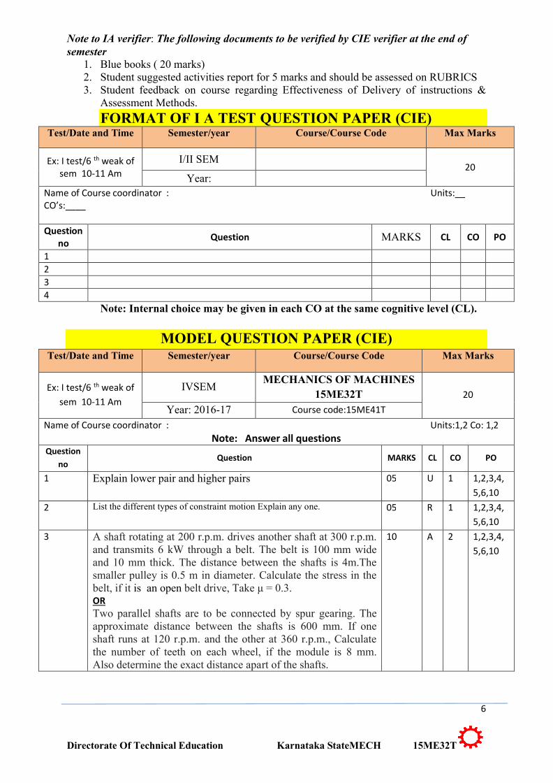
Note to IA verifier: The following documents to be verified by CIE verifier at the end of semester
1. Blue books ( 20 marks)2. Student suggested activities report for 5 marks and should be assessed on RUBRICS3. Student feedback on course regarding Effectiveness of Delivery of instructions &
Assessment Methods.
FORMAT OF I A TEST QUESTION PAPER (CIE)Test/Date and Time Semester/year Course/Course Code Max Marks
Ex: I test/6 th weak of sem 10-11 Am
I/II SEM20
Year:Name of Course coordinator : Units:__ CO’s:____
Question no Question MARKS CL CO PO
1234
Note: Internal choice may be given in each CO at the same cognitive level (CL).
MODEL QUESTION PAPER (CIE)Test/Date and Time Semester/year Course/Course Code Max Marks
Ex: I test/6 th weak of sem 10-11 Am
IVSEMMECHANICS OF MACHINES
15ME32T 20Year: 2016-17 Course code:15ME41T
Name of Course coordinator : Units:1,2 Co: 1,2Note: Answer all questions
Question no
Question MARKS CL CO PO
1 Explain lower pair and higher pairs 05 U 1 1,2,3,4,5,6,10
2 List the different types of constraint motion Explain any one. 05 R 1 1,2,3,4,5,6,10
3 A shaft rotating at 200 r.p.m. drives another shaft at 300 r.p.m. and transmits 6 kW through a belt. The belt is 100 mm wide and 10 mm thick. The distance between the shafts is 4m.The smaller pulley is 0.5 m in diameter. Calculate the stress in the belt, if it is an open belt drive, Take μ = 0.3.ORTwo parallel shafts are to be connected by spur gearing. The approximate distance between the shafts is 600 mm. If one shaft runs at 120 r.p.m. and the other at 360 r.p.m., Calculatethe number of teeth on each wheel, if the module is 8 mm. Also determine the exact distance apart of the shafts.
10 A 2 1,2,3,4,5,6,10
7
Directorate Of Technical Education Karnataka StateMECH 15ME32T
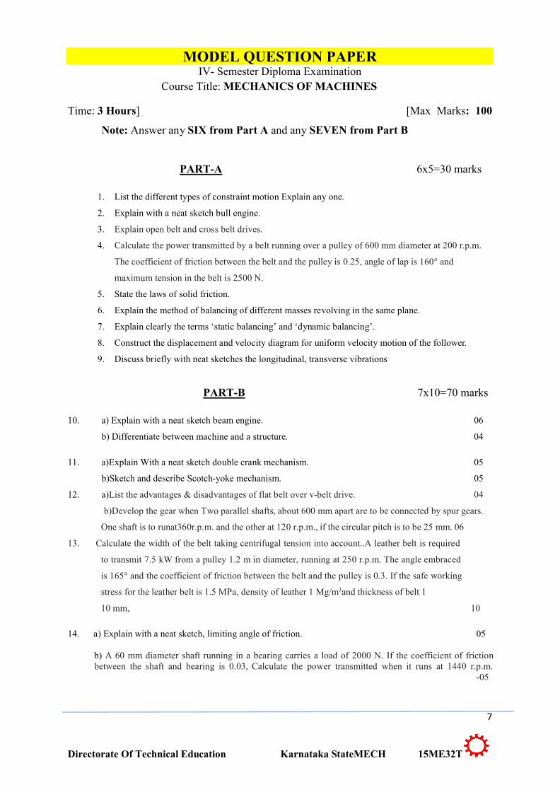
MODEL QUESTION PAPERIV- Semester Diploma Examination
Course Title: MECHANICS OF MACHINES
Time: 3 Hours] [Max Marks: 100
Note: Answer any SIX from Part A and any SEVEN from Part B
PART-A 6x5=30 marks
1. List the different types of constraint motion Explain any one.
2. Explain with a neat sketch bull engine.
3. Explain open belt and cross belt drives.
4. Calculate the power transmitted by a belt running over a pulley of 600 mm diameter at 200 r.p.m.
The coefficient of friction between the belt and the pulley is 0.25, angle of lap is 160° and
maximum tension in the belt is 2500 N.
5. State the laws of solid friction.
6. Explain the method of balancing of different masses revolving in the same plane.
7. Explain clearly the terms ‘static balancing’ and ‘dynamic balancing’.
8. Construct the displacement and velocity diagram for uniform velocity motion of the follower.
9. Discuss briefly with neat sketches the longitudinal, transverse vibrations
PART-B 7x10=70 marks
10. a) Explain with a neat sketch beam engine. 06
b) Differentiate between machine and a structure. 04
11. a)Explain With a neat sketch double crank mechanism. 05
b)Sketch and describe Scotch-yoke mechanism. 05
12. a)List the advantages & disadvantages of flat belt over v-belt drive. 04
b)Develop the gear when Two parallel shafts, about 600 mm apart are to be connected by spur gears.
One shaft is to runat360r.p.m. and the other at 120 r.p.m., if the circular pitch is to be 25 mm. 06
13. Calculate the width of the belt taking centrifugal tension into account..A leather belt is required
to transmit 7.5 kW from a pulley 1.2 m in diameter, running at 250 r.p.m. The angle embraced
is 165° and the coefficient of friction between the belt and the pulley is 0.3. If the safe working
stress for the leather belt is 1.5 MPa, density of leather 1 Mg/m3and thickness of belt 1
10 mm, 10
14. a) Explain with a neat sketch, limiting angle of friction. 05
b) A 60 mm diameter shaft running in a bearing carries a load of 2000 N. If the coefficient of friction between the shaft and bearing is 0.03, Calculate the power transmitted when it runs at 1440 r.p.m.
-05
8
Directorate Of Technical Education Karnataka StateMECH 15ME32T
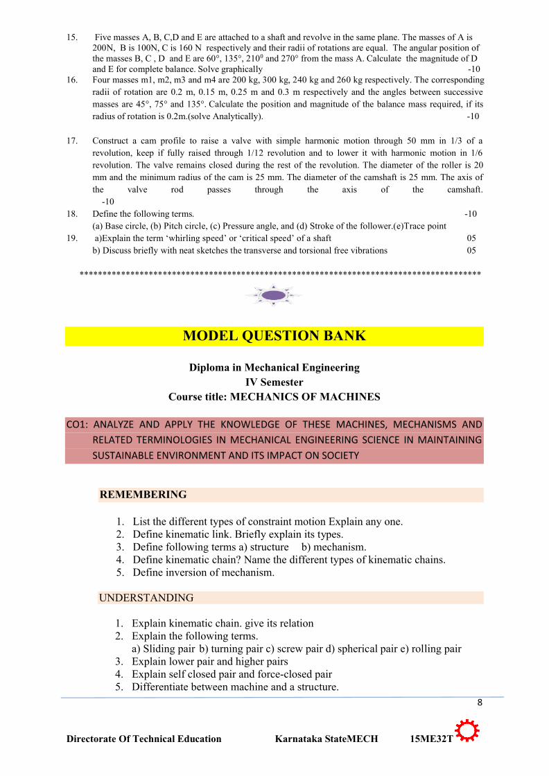
15. Five masses A, B, C,D and E are attached to a shaft and revolve in the same plane. The masses of A is 200N, B is 100N, C is 160 N respectively and their radii of rotations are equal. The angular position of the masses B, C , D and E are 60°, 135°, 2100 and 270° from the mass A. Calculate the magnitude of D and E for complete balance. Solve graphically -10
16. Four masses m1, m2, m3 and m4 are 200 kg, 300 kg, 240 kg and 260 kg respectively. The corresponding radii of rotation are 0.2 m, 0.15 m, 0.25 m and 0.3 m respectively and the angles between successive masses are 45°, 75° and 135°. Calculate the position and magnitude of the balance mass required, if its radius of rotation is 0.2m.(solve Analytically). -10
17. Construct a cam profile to raise a valve with simple harmonic motion through 50 mm in 1/3 of a revolution, keep if fully raised through 1/12 revolution and to lower it with harmonic motion in 1/6 revolution. The valve remains closed during the rest of the revolution. The diameter of the roller is 20 mm and the minimum radius of the cam is 25 mm. The diameter of the camshaft is 25 mm. The axis of the valve rod passes through the axis of the camshaft.
-1018. Define the following terms. -10
(a) Base circle, (b) Pitch circle, (c) Pressure angle, and (d) Stroke of the follower.(e)Trace point19. a)Explain the term ‘whirling speed’ or ‘critical speed’ of a shaft 05
b) Discuss briefly with neat sketches the transverse and torsional free vibrations 05
***************************************************************************************
MODEL QUESTION BANK
Diploma in Mechanical EngineeringIV Semester
Course title: MECHANICS OF MACHINES
CO1: ANALYZE AND APPLY THE KNOWLEDGE OF THESE MACHINES, MECHANISMS AND RELATED TERMINOLOGIES IN MECHANICAL ENGINEERING SCIENCE IN MAINTAINING SUSTAINABLE ENVIRONMENT AND ITS IMPACT ON SOCIETY
REMEMBERING
1. List the different types of constraint motion Explain any one.2. Define kinematic link. Briefly explain its types.3. Define following terms a) structure b) mechanism.4. Define kinematic chain? Name the different types of kinematic chains.5. Define inversion of mechanism.
UNDERSTANDING
1. Explain kinematic chain. give its relation2. Explain the following terms.
a) Sliding pair b) turning pair c) screw pair d) spherical pair e) rolling pair3. Explain lower pair and higher pairs4. Explain self closed pair and force-closed pair5. Differentiate between machine and a structure.
9
Directorate Of Technical Education Karnataka StateMECH 15ME32T
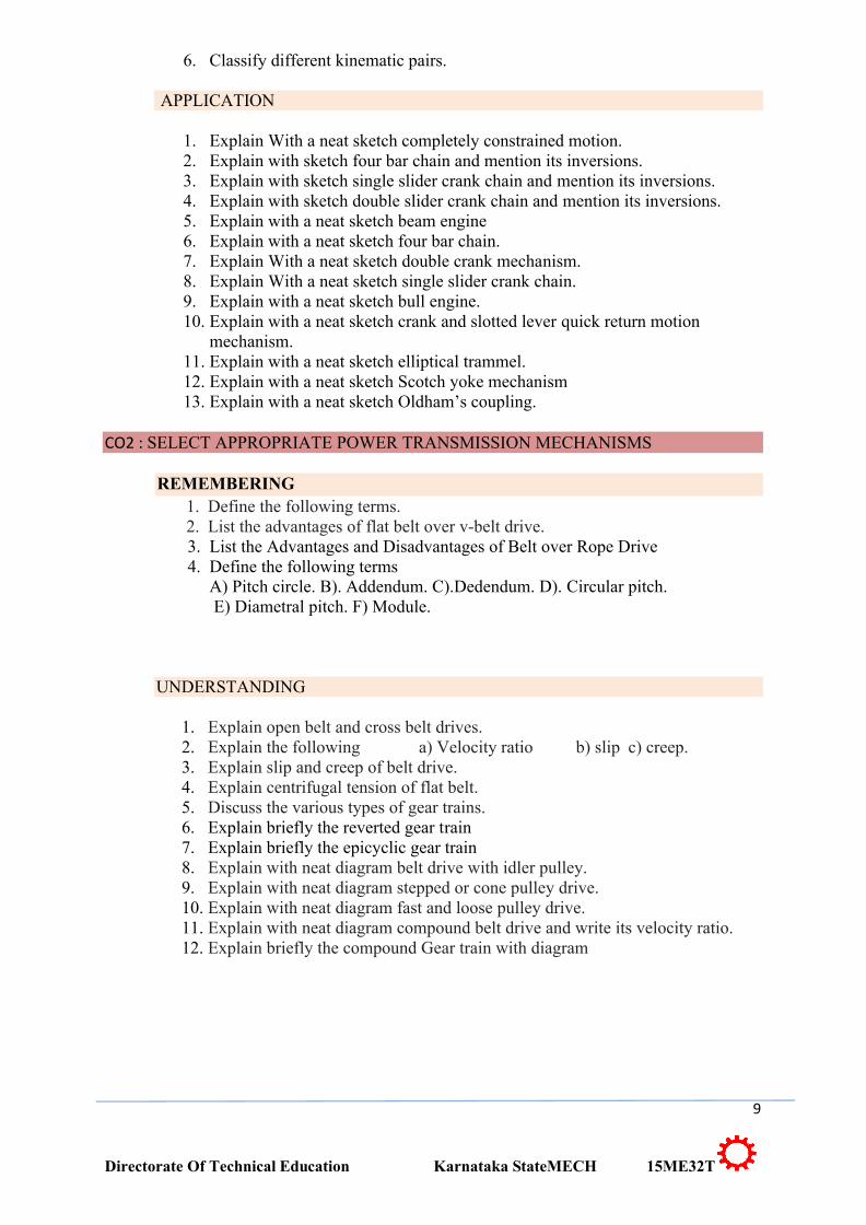
6. Classify different kinematic pairs.
APPLICATION
1. Explain With a neat sketch completely constrained motion.2. Explain with sketch four bar chain and mention its inversions.3. Explain with sketch single slider crank chain and mention its inversions.4. Explain with sketch double slider crank chain and mention its inversions.5. Explain with a neat sketch beam engine6. Explain with a neat sketch four bar chain.7. Explain With a neat sketch double crank mechanism.8. Explain With a neat sketch single slider crank chain.9. Explain with a neat sketch bull engine. 10. Explain with a neat sketch crank and slotted lever quick return motion
mechanism.11. Explain with a neat sketch elliptical trammel. 12. Explain with a neat sketch Scotch yoke mechanism13. Explain with a neat sketch Oldham’s coupling.
CO2 : SELECT APPROPRIATE POWER TRANSMISSION MECHANISMS
REMEMBERING1. Define the following terms.2. List the advantages of flat belt over v-belt drive.3. List the Advantages and Disadvantages of Belt over Rope Drive4. Define the following terms
A) Pitch circle. B). Addendum. C).Dedendum. D). Circular pitch.E) Diametral pitch. F) Module.
UNDERSTANDING
1. Explain open belt and cross belt drives.2. Explain the following a) Velocity ratio b) slip c) creep.3. Explain slip and creep of belt drive.4. Explain centrifugal tension of flat belt.5. Discuss the various types of gear trains.6. Explain briefly the reverted gear train7. Explain briefly the epicyclic gear train8. Explain with neat diagram belt drive with idler pulley.9. Explain with neat diagram stepped or cone pulley drive.10. Explain with neat diagram fast and loose pulley drive.11. Explain with neat diagram compound belt drive and write its velocity ratio.12. Explain briefly the compound Gear train with diagram
10
Directorate Of Technical Education Karnataka StateMECH 15ME32T
APPLICATION
1. An engine, running at 150 r.p.m., drives a line shaft by means of a belt. The engine pulley is 750 mm diameter and the pulley on the line shaft being 450 mm. A 900 mm diameter pulley on the line shaft drives a 150 mm diameter pulley keyed to a dynamo shaft. Calculate the speed of the dynamo shaft, when 1. There is no slip, and 2. There is a slip of 2% at each drive.
2. The power is transmitted from a pulley 1 m diameter running at 200 r.p.m. to a pulley 2.25 m diameter by means of a belt. Calculate the speed lost by the driven pulley as a result of creep, if the stress on the tight and slack side of the belt is 1.4 MPa and 0.5 MPa respectively. The Young’s modulus for the material of the belt is 100 MPa.
3. Calculate the power transmitted by a belt running over a pulley of 600 mm diameter at 200 r.p.m. The coefficient of friction between the belt and the pulley is 0.25, angle of lap is 160° and maximum tension in the belt is 2500 N.
4. Two pulleys, one 450 mm diameter and the other 200 mm diameter are on parallel shafts 1.95 m apart and are connected by a crossed belt. Calculate the length of the belt required and the angle of contact between the belt and each pulley. What power can be transmitted by the belt when the larger pulley rotates at 200 rev/min, if the maximum permissible tension in the belt is 1 kN, and the coefficient of friction between the belt and pulley is 0.25 ?
5. A shaft rotating at 200 r.p.m. drives another shaft at 300 r.p.m. and transmits 6 kW through a belt. The belt is 100 mm wide and 10 mm thick. The distance between the shafts is 4m.The smaller pulley is 0.5 m in diameter. Calculate the stress in the belt, if it is an open belt drive, Take μ = 0.3.
6. A leather belt is required to transmit 7.5 kW from a pulley 1.2 m in diameter, running at 250 r.p.m. The angle embraced is 165° and the coefficient of friction between the belt and the pulley is 0.3. If the safe working stress for the leather belt is 1.5 MPa, density of leather 1 Mg/m3and thickness of belt 10 mm, determine the width of the belt taking centrifugal tension into account.
7. Determine the width of a 9.75 mm thick leather belt required to transmit 15 kW from a motor running at 900 r.p.m. The diameter of the driving pulley of the motor is 300 mm. The driven pulley runs at 300 r.p.m. and the distance between the centres of two pulleys is 3 metres. The density of the leather is1000 kg/m3. The maximum allowable stress in the leather is 2.5 MPa. Theco-efficient of friction between the leather and pulley is 0.3. Assume open belt drive and neglect the sag and slip of the belt.
8. A pulley is driven by a flat belt, the angle of lap being 120°. The belt is 100 mm wide by 6 mm thick and density1000 kg/m3. If the coefficient of friction is 0.3 and the maximum stress in the belt is not to exceed 2 MPa, Calculate the greatest power which the belt can transmit and the corresponding speed of the belt.
9. In a flat belt drive the initial tension is 2000 N. The coefficient of friction between the belt and the pulley is 0.3 and the angle of lap on the smaller pulley is 150°. The smaller pulley has a radius of 200 mm and rotates at 500 r.p.m. Calculate the power in kW transmitted by the belt.
10. Two parallel shafts, whose centre lines are 4.8 m apart, are connected by open belt drive. The diameter of the larger pulley is 1.5 m and that of smaller pulley 1 m. The initial tension in the belt when stationary is 3 kN. The mass of the belt is 1.5 kg / m length. The coefficient of friction between the belt and the pulley is 0.3. Taking centrifugal tension into account, calculate the power transmitted, when the smaller pulley rotates at 400 r.p.m.
11
Directorate Of Technical Education Karnataka StateMECH 15ME32T
11. An open belt running over two pulleys 240 mm and 600 mm diameter connects two parallel shafts 3 metres apart and transmits 4 kW from the smaller pulley that rotates at 300 r.p.m. Co-efficient of friction between the belt and the pulley is 0.3 and the safe working tension is10N per mm width. Determine: 1. Minimum width of the belt, 2. Initial belt tension and 3. Length of the belt required.
12. Power is transmitted using a V-belt drive. The included angle of V-groove is 30°. The belt is 20 mm deep and maximum width is 20 mm. If the mass of the belt is 0.35 kg per meter length and maximum allowable stress is 1.4 MPa, determine the maximum power transmitted when the angle of lap is 140°. μ = 0.15.
13. A compressor, requiring 90 kW is to run at about 250 r.p.m. The drive is by V-belts from an electric motor running at 750 r.p.m. The diameter of the pulley on the compressor shaft must not be greater than 1 metre while the centre distance between the pulleys is limited to 1.75 metre. The belt speed should not exceed 1600 m/min. Determine the number of V-belts required to transmit the power if each belt has a cross-sectional area of 375 mm2, density 1000 kg/m3 and an allowable tensile stress of 2.5MPa. The groove angle of the pulley is 35°. The coefficient of friction between the belt and the pulley is 0.25.Calculate also the length required of each belt.
14. A rope drive transmits 600 kW from a pulley of effective diameter 4 m, which runs at a speed of 90 r.p.m. The angle of lap is 160° ; the angle of groove 45° ; the coefficient of friction 0.28 ; the mass of rope 1.5 kg / m and the allowable tension in each rope 2400 N. Calculate the number of ropes required.
15. A pulley used to transmit power by means of ropes has a diameter of 3.6 metres and has 15 grooves of 45° angle. The angle of contact is 170° and the coefficient of friction between the ropes and the groove sides is 0.28. Themaximum possible tension in the ropes is 960 N and the mass of the rope is 1.5 kg per metre length. Calculate the speed of pulley in r.p.m. and the power transmitted if the condition of maximum power prevail
16. Two parallel shafts, about 600 mm apart are to be connected by spur gears. One shaft is to run at 360 r.p.m. and the other at 120 r.p.m. Develop the gears, if the circular pitch isto be 25 mm.
17. Two parallel shafts are to be connected by spur gearing. The approximate distance between the shafts is 600 mm. If one shaft runs at 120 r.p.m. and the other at 360 r.p.m. Calculate the number of teeth on each wheel, if the module is 8 mm. Also determine the exact distance apart of the shafts.
18. A flat belt is required to transmit 35 kW from a pulley of 1.5 m effective diameter running at 300 r.p.m. The angle of contact is spread over 11/24 of the circumference and the coefficient of friction between belt and pulley surface is 0.3. Determine, taking centrifugal tension into account, width of the belt required. It is given that the belt thickness is 9.5 mm, density of its material is 1.1 Mg/m3 and the related permissible working stress is 2.5 MPa.
CO3: ANALYZE THE EFFECT OF FRICTION ON MACHINE ELEMENTS
UNDERSTANDING
1. Explain the following terms:(i).Angle of response (ii).Angle of friction
2. Explain limiting angle of friction.
12
Directorate Of Technical Education Karnataka StateMECH 15ME32T
3. Explain coefficient of friction.4. Explain with neat diagram limiting angle of friction.5. Explain with neat diagram coefficient of friction.6. Explain with neat diagram friction in a journal bearing.
APPLICATION
1. A 60 mm diameter shaft running in a bearing carries a load of 2000 N. If the coefficient of friction between the shaft and bearing is 0.03, Calculate the power transmitted when it runs at 1440 r.p.m.
2. Explain with neat sketch different types of pivot bearings.3. Explain with neat sketch single and multiple flat collar bearing.4. A vertical shaft 150 mm in diameter rotating at 100 r.p.m. rests on a flat end
footstep bearing. The shaft carries a vertical load of 20 kN. Assuming uniform pressure distribution and coefficient of friction equal to 0.05, Calculate power lost in friction.
5. A conical pivot supports a load of 20 kN, the cone angle is 120º and the intensity of normal pressure is not to exceed 0.3 N/mm2. The external diameter is twice the internal diameter. Calculate the outer and inner radii of the bearing surface. If the shaft rotates at 200 r.p.m. and the coefficient of friction is 0.1, Calculate the power absorbed in friction. Assume uniform pressure.
6. A conical pivot bearing supports a vertical shaft of 200 mm diameter. It is subjected to a load of 30 kN. The angle of the cone is 120º and the coefficient of friction is 0.025. Calculate the power lost in friction when the speed is 140 r.p.m., assuming uniform pressure.
7. A thrust shaft of a ship has 6 collars of 600 mm external diameter and 300 mm internal diameter. The total thrust from the propeller is 100 kN. If the coefficient of friction is 0.12 and speed of the engine90 r.p.m., Calculate the power absorbed in friction at the thrust block, assuming l. uniform pressure only
8. A shaft has a number of a collars integral with it. The external diameter of the collars is 400 mm and the shaft diameter is 250 mm. If the intensity of pressure is 0.35 N/mm2 (uniform) and the coefficient of friction is 0.05, Calculate:1. Power absorbed when the shaft runs at 105 r.p.m. carrying a load of 150 kN ; and 2. Number of collars required.
9. Explain with a neat sketch single plate or disc clutch.10. Explain with a neat sketch multi plate clutch.11. A single plate clutch, with both sides effective, has outer and inner diameters
300 mm and 200 mm respectively. The maximum intensity of pressure at any point in the contact surface is not to exceed 0.1 N/mm2. If the coefficient of friction is 0.3, determine the power transmitted by a clutch at a speed 2500rpm.
12. A multiple disc clutch has five plates having four pairs of active friction surfaces. If the intensity of pressure is not to exceed 0.127 N/mm2, Calculatethe power transmitted at 500 r.p.m. The outer and inner radii of friction surfaces are 125 mm and 75 mm respectively. Assume uniform wear and take coefficient of friction = 0.3.
13. Explain with a neat sketch internal expanding brake.
13
Directorate Of Technical Education Karnataka StateMECH 15ME32T
CO4:APPRECIATE THE ESSENTIALITY OF BALANCING IN ROTATING PARTS..
UNDERSTANDING
1. Explain the balancing of rotating parts necessary for high speed engines 2. Explain clearly the terms ‘static balancing’ and ‘dynamic balancing’.3. Discuss how a single revolving mass is balanced by a single mass revolving in
same planes.4. Explain the method of balancing of different masses revolving in the same plane.
APPLICATION
1. Four masses m1, m2, m3 and m4 are 200 kg, 300 kg, 240 kg and 260 kg respectively. The corresponding radii of rotation are 0.2 m, 0.15 m, 0.25 m and 0.3 m respectively and the angles between successive masses are 45°, 75° and 135°. Calculate the position and magnitude of the balance mass required, if its radius of rotation is 0.2 m.(Analytical method)
2. Four masses m1, m2, m3 and m4 are 250 kg, 350 kg, 290 kg and 310 kg respectively. The corresponding radii of rotation are 0.25 m, 0.20 m, 0.35 m and 0.4 m respectively and the angles between successive masses are 45°, 75° and 135°. Calculate the position and magnitude of the balance mass required, if its radius of rotation is 0.25 m. (Graphical method)
3. Four masses A, B, C and D are attached to a shaft and revolve in the same plane. The masses are 12kg, 10 kg, 18 kg and 15 kg respectively and their radii of rotations are 40 mm, 50 mm, 60 mm and30 mm. The angular position of the masses B, C and D are 60°, 135° and 270° from the mass A. Calculate the
magnitude and position of the balancing mass at a radius of 100 mm.4. Five masses A, B, C,D and E are attached to a shaft and revolve in the same
plane. The masses of A is 200N, B is 100N, C is 160 N respectively and their radii of rotations are equal. The angular position of the masses B, C , D and E are 60°, 135°, 2100 and 270° from the mass A. Calculate the magnitude of D and E for complete balance. Solve graphically.
5. Five masses A, B, C,D and E are attached to a shaft and revolve in the same plane. The masses of A is 250N, B is 160 N, C is 210N respectively and their radii of rotations are equal. The angular position of the masses B, C , D and E are 60°, 135°, 2100 and 270° from the mass A. Calculate the magnitude of D and E for complete balance. Solve by Analytical method.
6. Four masses m1, m2, m3 and m4 are 100 N, 150 N, 120 N and 130 N respectively. The corresponding radii of rotation are 0.225 m, 0.175 m, 0.25 m and 0.3 m respectively and the angles measured from A are 45°,
1200 and 255°. Calculate the position and magnitude of the balance mass required, if its radius of rotation is 0.3 m.( Analytical method)
7. Four masses A, B, C and D are attached to a shaft and revolve in the same plane. The masses are 16kg, 14 kg, 22kg and 20 kg respectively and their radii of rotations are 40 mm, 50 mm, 60 mm and 30 mm. The angular position of
14
Directorate Of Technical Education Karnataka StateMECH 15ME32T
the masses B, C and D are 60°, 135° and 270° from the mass A. Calculate the magnitude and position of the balancing mass at a radius of 50 mm
CO5: CONSTRUCT CAM PROFILE FOR THE SPECIFIC FOLLOWER MOTION
REMEMBERING1. Define the following terms.
(a) Base circle, (b) Pitch circle, (c) Pressure angle, and (d) Stroke of the follower.(e)Trace point
UNDERSTANDING1. Explain cam and follower2. Classify different types of cams3. Describe the types of follower.4. Classify different types of followers.5. Explain prime circle and pitch circle related to cam profile6. Explain base circle and pitch point to cam profile7. Explain pressure angle and lift or stroke related to cam profile8. Interpret why a roller follower is preferred to that of a knife-edged
follower.9. Illustrate the different types of motion with which a follower can move.
APPLICATION
1. Construct the displacement diagram for uniform velocity and S.H.M motion of the follower
2. Construct the displacement and velocity diagram S.H.M motion of the follower
3. Construct the displacement and velocity diagram for uniform velocity motion of the follower
4. Construct the displacement and velocity diagram for uniform acceleration and retardation motion of the follower.
5. Explain with sketches the different types of cams and followers.
6. Construct a disc cam to give uniform motion to a knife edge follower during out stroke of 50 mm during the first half of the cam revolution. The follower again returns to its original position with uniform motion during the next half of the revolution. The minimum radius of the cam is 50 mm and the diameter of the cam shaft is 35 mm. Draw the profile of the cam when the axis of follower passes through the axis of cam shaft.
7. Construct a cam operating a knife-edged follower, has the following data :(a) Follower moves outwards through 40 mm during 60° of cam rotation.(b) Follower dwells for the next 45°.(c) Follower returns to its original position during next 90°.(d) Follower dwells for the rest of the rotation.(e) The displacement of the follower is to take place with simple harmonic
motion during both the outward and return strokes. The least radius of the
15
Directorate Of Technical Education Karnataka StateMECH 15ME32T
cam is 50 mm. Draw the profile of the cam when the axis of the follower is offset 20mm towards right from the cam axis.
8. Construct a disc cam rotating in a clockwise direction is used to move a reciprocating roller with simple harmonic motion in a radial path for the details given below:a) Outstroke with maximum displacement of 25 mm during 120° of cam rotation,b) Dwell for 60° of cam rotation,c) iii) Return stroke with maximum displacement of 25 mm during 90° of cam
rotation, andd) Dwell during remaining 90° of cam rotation.e) The line of reciprocation of follower passes through the camshaft axis. The
maximum radius of camis30 mm. The roller diameter is 8 mm. Draw the profile of the cam when the line of reciprocation of the follower is offset by 20 mm towards right from the cam shaft axis.
9. Construct a cam profile to raise a valve with simple harmonic motion through 50 mm in 1/3 of a revolution, keep if fully raised through 1/12 revolution and to lower it with harmonic motion in 1/6 revolution. The valve remains closed during the rest of the revolution. The diameter of the roller is 20 mm and the minimum radius of the cam is 25 mm. The diameter of the camshaft is 25 mm. The axis of the valve rod passes through the axis of the camshaft.
10.Construct a cam rotating clockwise with a uniform speed is to give the roller follower of 20 mm diameter with the following motion:
i. Follower to move outwards through a distance of 30 mm during 120° of cam rotation ;
ii. Follower to dwell for 60° of cam rotation ;iii. Follower to return to its initial position during 90° of cam rotation ; andiv. Follower to dwell for the remaining 90° of cam rotation.
The minimum radius of the cam is 30 mm and the line of stroke of the follower is offset 15 mm from the axis of the cam and the displacement of the follower is to take place with simple harmonic motion on both the outward and return strokes. Draw the cam profile.
11. Construct the profile of cam rotating clockwise at a uniform speed of 100 r.p.m. is required to give motion to knife-edge follower as below, Follower to move outwards through 40 mm during 120° of cam rotation,
(f) Follower to dwell for the next 60° of cam rotation,(g) Follower to return to its starting position during next 90° of cam rotation, and(h) Follower to dwell for the rest of the cam rotation.(i) The minimum radius of the cam is 30 mm and the line of stroke of the
follower passes through the axis of the cam shaft. If the displacement of the follower takes place with uniform and equal acceleration and retardation on both the outward and return strokes.
12. Construct a cam profile with 30 mm as minimum diameter is rotating clockwise at a uniform speed of 1200 r.p.m. and has to give the following motion to a roller follower 10 mm in diameter:
16
Directorate Of Technical Education Karnataka StateMECH 15ME32T
(a) Follower to complete outward stroke of 25 mm during 120° of cam rotation with equal uniform acceleration and retardation ;
(b) Follower to dwell for 60° of cam rotation;(c) Follower to return to its initial position during 90° of cam rotation with equal
uniform acceleration and retardation;(d) Follower to dwell for the remaining 90° of cam rotation.
Draw the cam profile if the axis of the roller follower passes through the axis of the cam.
13. Construct a cam profile, rotating clockwise at a uniform speed of 200 r.p.m. is required to move an offset roller follower with a uniform and equal acceleration and retardation on both the outward and return strokes. The
angle of ascent, the angle of dwell (between ascent and descent) and the angle of descent is 120°, 60° and 90° respectively. The follower dwells for the rest of cam rotation. The least radius of the cam is 50 mm, the lift of the follower is 25 mm and the diameter of the roller is 10mm. The line of stroke of the follower is offset by 20 mm from the axis of the cam.
14. Construct the profile of a cam to suit the following specifications:Cam shaft diameter = 25mm; Least radius of cam = 30 mm ; Diameter of roller = 20 mm;Angle of lift = 120° ; Angle of fall = 150° ; Lift of the follower = 40 mm ; Number of pauses are two of equal interval between motions. During the lift, the motion is S.H.M. During the fall the motion is uniform acceleration and deceleration. The speed of the cam shaft is uniform. The line of stroke of the
follower is off-set12.5 mm from the centre of the cam.15. Construct the profile of a cam to give the following motion to a knife-edged
follower:Outstroke during 60° of cam rotation: 2. Dwell for the next 30° of cam rotation;Return stroke during next 60° of cam rotation, and 4. Dwell for the remaining 210° of cam Rotation. The stroke of the follower is 40 mm and the minimum radius of the cam is 50 mm. The follower moves with uniform velocity during the outstroke and return strokes. With uniform velocity. Draw the profile of the cam when the axis of the follower is offset by 20 mm from the axis of the cam shaft.
CO6: UNDERSTAND THE TERMINOLOGY AND TYPES ASSOCIATED WITH VIBRATION IN MACHINE ELEMENTS
REMEMBERING
1. Define free vibrations, forced vibrations.2. Identify the causes and effects of vibrations?3. Define free vibrations,. And damped vibrations.4. Define forced vibrations,. And damped vibrations.
UNDERSTANDING

17
Directorate Of Technical Education Karnataka StateMECH 15ME32T
1. Discuss briefly with neat sketches the longitudinal, transverse vibrations.2. Discuss briefly with neat sketches the transverse and torsional free vibrations.3. Discuss briefly with neat sketches the longitudinal, and torsional free
vibrations.4. Explain the term ‘whirling speed’ or ‘critical speed’ of a shaft