Course No: M04-033 Credit: 4 PDH - CED Engineering Gear Fundamentals.pdf · Basic Gear Fundamentals...
29
Basic Gear Fundamentals Course No: M04-033 Credit: 4 PDH Robert P. Tata, P.E. Continuing Education and Development, Inc. 9 Greyridge Farm Court Stony Point, NY 10980 P: (877) 322-5800 F: (877) 322-4774 [email protected]
Transcript of Course No: M04-033 Credit: 4 PDH - CED Engineering Gear Fundamentals.pdf · Basic Gear Fundamentals...

Basic Gear Fundamentals Course No: M04-033
Credit: 4 PDH
Robert P. Tata, P.E.
Continuing Education and Development, Inc. 9 Greyridge Farm Court Stony Point, NY 10980 P: (877) 322-5800 F: (877) 322-4774 [email protected]

Basic Gear Fundamentals
Copyright 2012 Robert P. Tata
All Rights Reserved

2
Table of Contents
Subject Page
Introduction 3 Terminology 5 Types 9 Manufacturing 11 Spur Gear Design 13 Ratings 14 Rim and Shaft Design 16 Design Alternatives 19 Helical Gears 20 Bevel Gears 21 Application 22 Appendix I 27 Appendix II 28

3
Introduction Gears are wheel-like machine elements that have teeth uniformly spaced around the outer surface. They are used in pairs and are a very valuable design tool. Gears are mounted on rotatable shafts and the teeth are made to mesh (engage) with a gear on another shaft. Gears deliver force (torque) and motion (rpm) from one part of a machine to another. A gear driven by another gear 3/4 its own size will rotate at 3/4 the speed of the drive gear and deliver 4/3 the torque. Being able to control speed and torque by varying the number of teeth of one gear, with respect to another (ratio), makes gears a valuable design tool. An automobile transmission is an excellent example of how this principle is put to use in controlling vehicle motion. Figure 1 has three gears in train. The first gear known as the driver has 12 teeth, the second gear called the idler has 16 teeth, and the third gear known as the driven also has 16 teeth. If the driver rotates at 400 rpm, the idler rotates at 300 rpm, and the driven gear also rotates at 300 rpm. If the driver input torque is 300 inch-pounds, the idler torque is 400 inch-pounds, and the driven gear torque is also 400 inch-pounds. Since the speed of rotation and torque of the idler and driven gear are the same, it can be seen that, in this case, the purpose of the idler is merely to change the direction of rotation of the driven gear to match that of the drive gear. It is interesting to note that since the idler has two meshes instead of one as do the other two gears, two-direction bending occurs on idler gear teeth while only one-direction bending occurs on the driver and driven gear teeth. This has the effect of reducing the operational life of the idler gear significantly over that of the other two gears.

Figure 1 Gears Delivering Motion (rpm)
And Force (in-lbs)
4

5
Terminology The gear tooth is a component of a mechanical power transmission system that does not lack for descriptive terminology. The pitch circle is a circle on the face of a gear that passes through points that are radially half way up the working depth of the teeth. See Figure 2. It is a basic dimension from which many other features of the teeth are referenced. The pitch circle diameter is a dimension on each of two gears in mesh that when divided by each other equal the ratio. Diametral pitch which is a measure of tooth size equals the number of teeth divided by the pitch diameter. The radial dimension from the pitch circle to the tip of the tooth is called the addendum. The radial surface from the pitch circle to the very bottom of the tooth is called the dedendum. The curved surfaces of the two gear faces are in the form of involute curves. The slope of the involute curve at the pitch diameter is called the pressure angle. Lower pressure angle teeth have steeper sides than high pressure angle teeth while higher pressure angle teeth are wider at the base and narrower at the tip. The various terms are listed below and shown on Figure 2:
•Pinion is the smaller of two gears in mesh. The larger is called the gear regardless of which one is doing the driving. •Ratio is the number of teeth on the gear divided by the number of teeth on the pinion. •Pitch Diameter is the basic diameter of the pinion and gear which when divided by each other equals the ratio. •Diametrical Pitch is a measure of tooth size and equals the number of teeth on a gear divided by the pitch diameter in inches. Diametrical pitch can range from 1/2 to 200 with the smaller number indicating a larger tooth. See Figure 3. •Module is a measure of tooth size in the metric system. It equals the pitch diameter in millimeters divided by the number of teeth on a gear. Module equals 25.400 divided by the diametral pitch. Module can range from 0.2 to 50 with the smaller number indicating a smaller tooth. •Pitch Circle is the circumference of the pitch diameter.

6
•Circular Pitch is the distance along the pitch circle from a point on one gear tooth to the same point on an adjacent gear tooth as shown on the sketch at the bottom of Figure 3.
•Addendum of a tooth is its radial height above the pitch circle. The addendum of a standard proportion tooth equals 1.000 divided by the diametral pitch. The addendum of a pinion and mating gear are equal except for the long addendum design where the pinion addendum is increased while the gear addendum is decreased by the same amount. •Dedendum of a tooth is its radial depth below the pitch circle. The dedendum of a standard proportion tooth equals 1.250 divided by the diametral pitch. The dedendum for a pinion and mating gear are equal except in the long addendum design where the pinion dedendum is decreased while the gear dedendum is increased by the same amount. •Whole Depth or total depth of a gear tooth equals the addendum plus the dedendum. The whole depth equals 2.250 divided by the diametral pitch. •Working Depth of a tooth equals the whole depth minus the height of the radius at the base of the tooth. The working depth equals 2.000 divided by the diametral pitch. •Clearance equals the whole depth minus the working depth. The clearance equals the height of the radius at the base of the tooth. •Pressure Angle is the slope of the tooth at the pitch circle.

Figure 2 Gear Tooth Terminology
7

Figure 3 Gear Tooth Size
8

9
Types There are four basic types of gears; spur, helical, bevel, and spiral bevel. See Figure 4. Spur gears are the most common. A spur gear has teeth that are uniformly spaced around the outer surface. The teeth are aligned in a direction that is parallel to the gear axis. A spur gear is designed to mesh with another spur gear on a parallel shaft. Spur gears impose only radial (perpendicular to axis) loads on gear shafts as opposed to helical, bevel, and spiral bevel gears which impose both radial and thrust (axial) loads on gear shafts. The profile of the contact surface of spur gear teeth is in the form of an involute curve. An involute curve is the path that the end of a string takes when it is being unwound from a cylinder. The shape is easy to manufacture and is an efficient way to transmit power between two gear teeth because of the tendency to maximize rolling and minimize sliding. The efficiency of spur gears is in the high 90% range and approaches that of anti-friction bearings. Helical gears are like spur gears except that the teeth are positioned at an angle to the gear axis of rotation. This angle, called the helix angle, is normally 10° to 30°. Helical gears are stronger and operate more quietly than comparable size spur gears. Helical gears are less efficient than spur gears and impose thrust as well as radial loads on shafts making bearing selection more complex. Double helical gears or "herringbone" gears impose radial loads only on shafts and bearings. Bevel gears are like spur gears except that the basic configuration is conical in shape. Bevel gears are used to transmit motion between two shafts that are not parallel. Two shafts that are at a 90° angle are connected by bevel gears. Bevel gears, like spur gears, operate at efficiencies in the high 90% range. Bevel gears are used in automotive vehicles, aircraft, and machine tools. Spiral bevel gears have teeth that are cut at an angle similar to the way helical gear teeth are cut. Spiral bevel gears operate at lower efficiencies than bevel gears. Spiral bevel gears whose axes do not intersect are called hypoid gears. Hypoid gears are used in automotive rear axles to lower the drive shaft and increase passenger space.
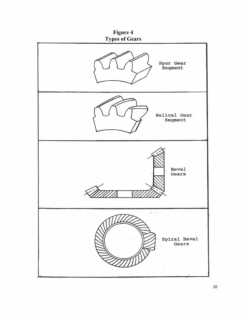
Figure 4 Types of Gears
10
11
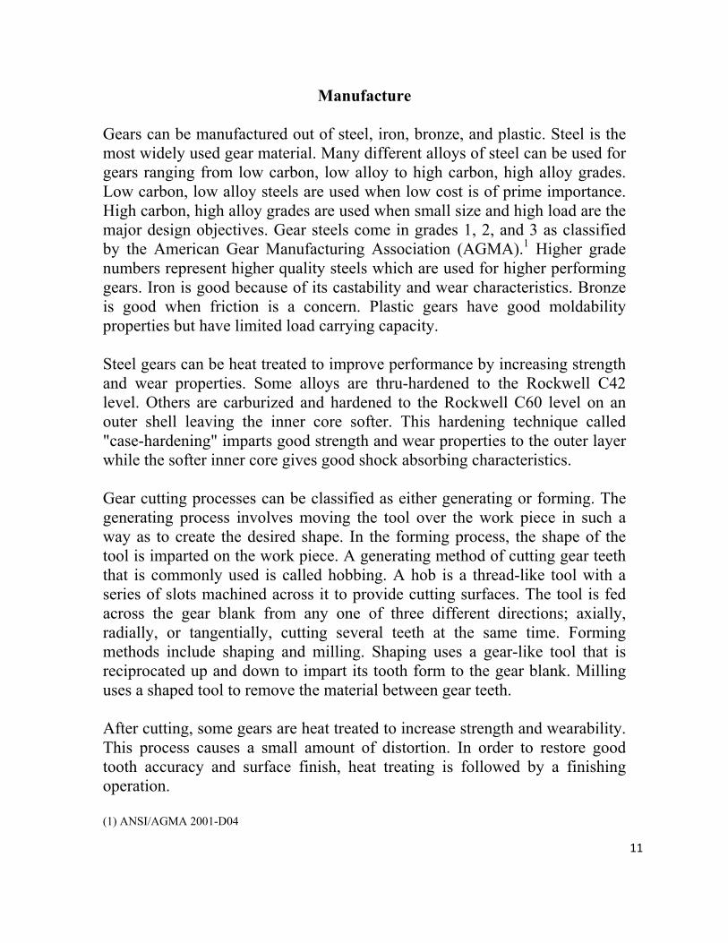
Manufacture Gears can be manufactured out of steel, iron, bronze, and plastic. Steel is the most widely used gear material. Many different alloys of steel can be used for gears ranging from low carbon, low alloy to high carbon, high alloy grades. Low carbon, low alloy steels are used when low cost is of prime importance. High carbon, high alloy grades are used when small size and high load are the major design objectives. Gear steels come in grades 1, 2, and 3 as classified by the American Gear Manufacturing Association (AGMA).1 Higher grade numbers represent higher quality steels which are used for higher performing gears. Iron is good because of its castability and wear characteristics. Bronze is good when friction is a concern. Plastic gears have good moldability properties but have limited load carrying capacity. Steel gears can be heat treated to improve performance by increasing strength and wear properties. Some alloys are thru-hardened to the Rockwell C42 level. Others are carburized and hardened to the Rockwell C60 level on an outer shell leaving the inner core softer. This hardening technique called "case-hardening" imparts good strength and wear properties to the outer layer while the softer inner core gives good shock absorbing characteristics. Gear cutting processes can be classified as either generating or forming. The generating process involves moving the tool over the work piece in such a way as to create the desired shape. In the forming process, the shape of the tool is imparted on the work piece. A generating method of cutting gear teeth that is commonly used is called hobbing. A hob is a thread-like tool with a series of slots machined across it to provide cutting surfaces. The tool is fed across the gear blank from any one of three different directions; axially, radially, or tangentially, cutting several teeth at the same time. Forming methods include shaping and milling. Shaping uses a gear-like tool that is reciprocated up and down to impart its tooth form to the gear blank. Milling uses a shaped tool to remove the material between gear teeth. After cutting, some gears are heat treated to increase strength and wearability. This process causes a small amount of distortion. In order to restore good tooth accuracy and surface finish, heat treating is followed by a finishing operation. (1) ANSI/AGMA 2001-D04

12
For gears that are heat treated to hardness below Rockwell C42, a finishing operation called shaving is performed. Shaving is similar to shaping except that the tool teeth are grooved to provide additional cutting edges to remove a small amount of material. For gears that are heat treated to a hardness of Rockwell C42 and higher, grinding is used as the finishing operating. Grinding can be a generating or forming method of finishing gears. The generating method passes an abrasive wheel over the gear teeth in a prescribed path to true up the teeth and produce a fine surface finish. The forming method feeds a shaped wheel between the gear teeth similar to milling. Gears can be manufactured over a very wide size range. They can range from a fraction of an inch in diameter to many feet in diameter. Gear tooth height can vary from .001 inch (200 diametral pitch) to 4.31 inches (1/2 diametral pitch). Metric tooth height sizes vary from .431 millimeters (0.2 module) to 107.85 millimeters (50 module). Gear teeth are normally manufactured with pressure angles of 14.5°, 20°, or 25°. As the pressure angle is made larger, the teeth become wider at the base and narrower at the tip. This makes the teeth stronger and able to carry more load but more apt to chip at the tip if not properly designed. Pinions with higher pressure angles can be made with fewer teeth because of there being less danger of undercutting. Undercutting is a narrowing of the bottom of the teeth when being manufactured. Lower pressure angle teeth have a narrower base and carry less load than higher pressure angle teeth but the teeth are wider at the tip and less apt to chip. Finally, lower pressure angle teeth mesh more smoothly and quietly than higher pressure angle teeth because of having higher contact ratios. Contact ratio is a measure of the average number of teeth in engagement at the same time during gear operation.
13
Spur Gear Design As a sample calculation, a step-by-step procedure will be demonstrated on how to design a spur gearset (pinion and gear) for a general industrial application. The gearset shall be rated for 100 horsepower at a pinion speed of 1000 revolutions per minute. It shall have a ratio of 8 to 1 and use standard proportion 25° pressure angle teeth. The material will be Grade 1 Rockwell C60 case-hardened steel. Initially, a determination must be made as to the number of teeth in the pinion. The object is to keep the number of teeth as low as possible in order to minimize cost and weight while still fulfilling all the design objectives. From AGMA, the fewest number of standard 25° pressure angle teeth that a pinion can have is 14.2 Fewer than 14 will cause undercutting which, as previously mentioned, is a narrowing or weakening of the base of gear teeth. As a general rule of thumb for this application, the number of teeth in the pinion should be 30 for low ratio (1/1) to 14 for high ratio (10/1) gearsets. As a result, a pinion with 17 teeth will be selected for the 8 to 1 ratio gearset to be designed. An 8 to 1 gearset ratio requires the gear to have 8x17=136 teeth. A tooth ratio of 136 to 17 is not a "hunting ratio". Hunting ratios occur when each pinion tooth contacts every gear tooth before it contacts any gear tooth a second time. Hunting ratios tend to equalize tooth wear and improve tooth spacing. The test for a hunting ratio is that the number of teeth in the pinion and, separately, the number of teeth in the gear, cannot be divided by the same number, excluding 1. Both numbers in a 136 to 17 ratio gearset can be divided by 17. In order to make the ratio a hunting ratio, a tooth will be dropped from the gear and a hunting ratio of 135 to 17 will be used. The new ratio of 7.9 to 1 is close enough to 8 to 1 for this application. (2) AGMA 908-B89

14
Spur Gear Rating There are a number of ways to rate spur gears. AGMA offers two ways to do it. One way calculates the allowable transmitted horsepower on the pitting resistance of gear teeth contact surfaces while the other calculates transmitted horsepower on gear teeth bending strength.1 The two equations will be used to evaluate the above mentioned standard proportion 25° pressure angle gearset. A minimum rating of 100 hp from each of the two AGMA equations is required. Three different diametral pitches (tooth sizes) will be investigated. The diametral pitches are 7.0, 6.5, and 6.0. The AGMA equation for tooth pitting transposed down to one line follows. For the sake of brevity, all modifying factors are assumed to be 1 and have been omitted. In actual practice, they can alter the results significantly and therefore must be used. Pac = (πnpFI / 396,000)(dsac /Cp)2
Pac is the pitting resistance allowable transmitted horsepower for ten million cycles of operation at 99% reliability. π is a constant and equals 3.142. np is the pinion speed which is 1000 rpm. F is the face width and, as a general rule of thumb for industrial gears, equals d, the pinion pitch diameter, calculated below. I is the geometry factor for pitting which equals .132.2 d is the pinion pitch diameter and for the three diametral pitches equals 17/7=2.429 in, 17/6.5=2.615 in, and 17/6=2.833 in. sac is the allowable contact stress and from AGMA equals 180,000 psi for Grade 1 case-hardened steel.1 Cp is the elastic coefficient and from AGMA equals 2300 psi.5.1 The calculations are listed in Appendix I. The AGMA equation for tooth bending transposed down to one line follows. Again, for the sake of brevity, the modifying factors have been assumed to be 1 and have been omitted. In actual practice, they must be used which can result in significant changes to the calculation. Pat=(πnpdFJsat) / (396,000Pd)

15
Pat is the tooth bending strength allowable transmitted horsepower for 10 million cycles of operation at 99% reliability. π equals 3.142 np is the pinion speed which is 1000 rpm. d is the pinion pitch diameter and for the three diametral pitches equals 17/7=2.429 in, 17/6.5=2.615 in, and 17/6=2.833 in. F is the face width and, as a general rule of thumb for industrial gears, equals d, the pinion pitch diameter calculated above. J is the tooth geometry factor and equals .38 for the pinion and .52 for the gear. The more conservative .38 will be used. sat is the allowable bending stress and from AGMA equals 55,000 psi for Grade 1 case-hardened steel.* Pd is the diametral pitch which equals 7.0, 6.5, and 6.0. The calculations for bending are also listed in Appendix I. It can now be seen that the pitting results are lower so they, being the more conservative numbers, will be used to rate the gearset. The 115 hp, 6.5 pitch design is selected based on being the most economical choice to fulfill design objectives. (1) ANSI/AGMA 2001-D04 (2) AGMA 908-B89

16
Gear Rim and Shaft Design
The gear rim is the ring of material that lies under the gear teeth that serves to hold and support the gear teeth. The gear rim must be of sufficient radial thickness to prevent fatigue cracks from propagating through the rim rather than through the gear teeth. AGMA recommends that gear rim thickness be no less than 1.2 times whole tooth depth.1 Figure 5 shows the minimum rim thickness for a 3 diametral pitch tooth. An equation is presented by AGMA that downgrades bending strength transmitted power ratings for gears with insufficient rim thickness. The equation is as follows: KB=1.6ln(2.242/mB) KB is the factor which must be used to downgrade bending horsepower ratings when rim thickness is less than 1.2 times tooth whole depth. mB is the ratio of the rim thickness to the tooth whole depth. In Figure 5, if the rim thickness were .80 inch, the above equation would be as follows: KB=1.6ln[(2.242/(.80/.75)]=1.189 The tooth bending horsepower would be reduced by a factor of 1.189 because of inadequate rim thickness. The following equation taken from "Code for the Design of Transmission Shafting" will be used to determine the minimum shaft diameter needed to support the 115 hp design option:3
D={(16/πpt)[(KmM)2+(KtT)2]1/2}1/3
D is the minimum outside diameter of a solid shaft in inches needed to support bending and torsional loading. π is a constant which equals 3.142. pt is maximum intensity of the shearing stress on the shaft in pounds per square inch. Km is a shock and fatigue factor for steady loads which equals 1.5 for a rotating shaft. M is the maximum bending moment in pound inches. Kt is the shock and fatigue factor for steady loads which equals 1.0 for a rotating shaft.

17
T is the maximum torsional load in inch-pounds. The calculations are in Appendix I where it can be seen that the maximum internal diameter of the gear must be 1.401 inches for adequate rim thickness and that the minimum required diameter of the gear shaft must be 1.391 inches for adequate strength. (1) ANSI/AGMA 2001-D04 (3) Article courtesy of Mechanical Engineering magazine Vol.49/No.5, May, 1927 474-476; copyright Mechanical Engineering magazine (the American Society of Mechanical Engineers)
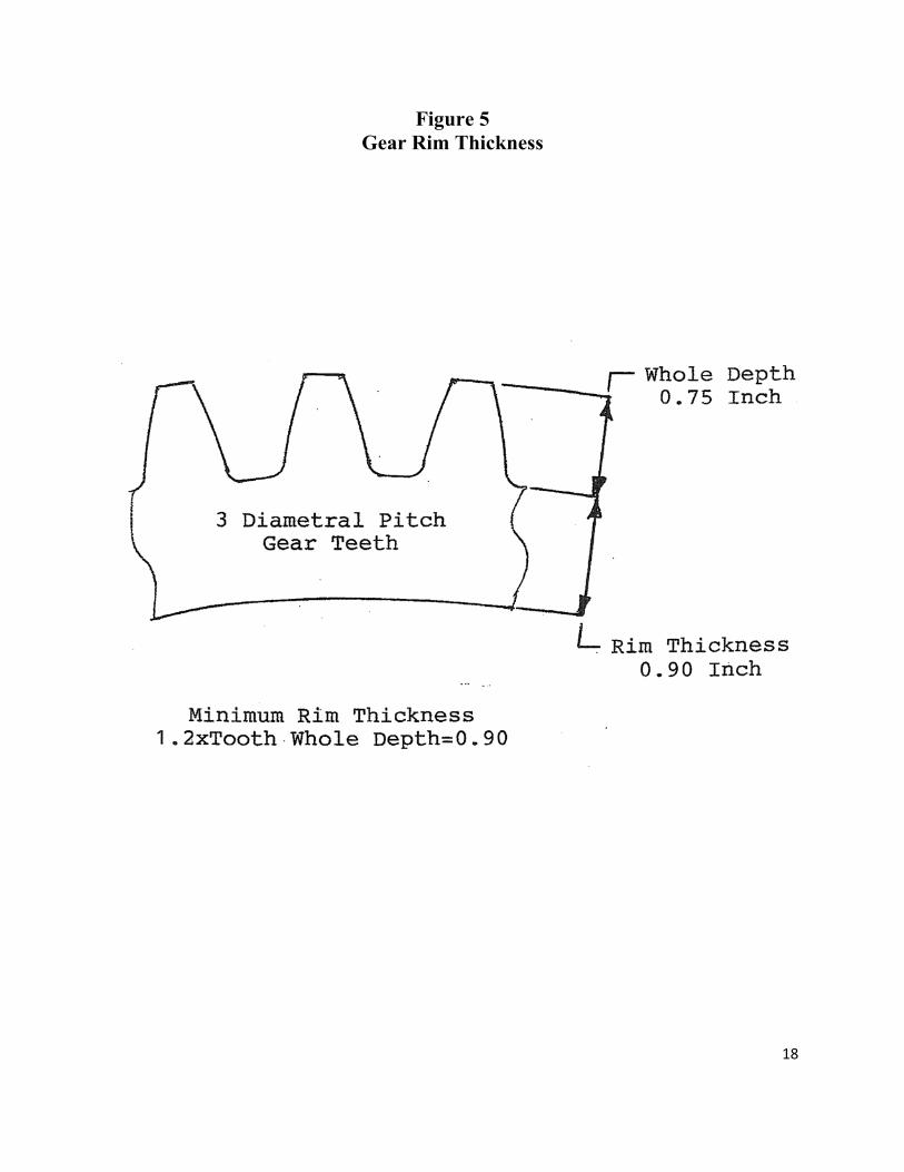
Figure 5 Gear Rim Thickness
18
19
Design Alternatives
There are a number of ways to improve the performance of a gearset without increasing the design envelope. One way has already been incorporated. Using 25° pressure angle teeth is an improvement over lower pressure angle teeth because, as explained, 25° pressure angle teeth are wider at the base and can deliver more power than lower pressure angle teeth. Normally in a gearset, the pinion is weaker than the gear. In order to equalize the strength of the two, a tooth modification factor called "long addendum" is used. As previously explained, in the long addendum design, the pinion addendum is increased while the gear addendum is decreased by the same amount. This increases the pinion bending strength and reduces the stresses that cause pitting failure. In the previous sample problem, standard length pinion and gear addenda were used. When the pinion addendum is increased to 125%, the only item that changes in the pitting equation is the tooth geometry factor which increases from .132 to .151.2 This increases the 115 hp rating to 131 horsepower. In the preceding example, grade 1 steel was used; however, performance can be enhanced by using higher grade material. The only item that changes in the equation is the allowable contact stress which increases from 180,000 psi to 275,000 psi for grade 3 case-hardened steel.1 The 115 hp grade 1 case-hardened steel design, upgraded to grade 3 material, increases to 268 horsepower. Even higher gains in horsepower can be made by combining the above two features. (1) AMSI/AGMA 2001-D04 (2) AGMA 908-B89

20
Helical Gears Helical gear teeth, as previously mentioned, are aligned at an angle to the gear axis as opposed to being parallel to the gear axis as are spur gear teeth. The angle is called the helix angle. Helical gears are stronger and can transmit more power than spur gears. The 115 horsepower design of the previous exercise, if replaced by 30° angle helical gears, will transmit 222 horsepower, again, because of only a change in the equation geometry factor. Even higher gains can be made with helical gears by incorporating long addendum design and higher grade material. Helical gears however, impose thrust as well as radial loads on gearshifts making shaft strength and support bearing selection more critical. The ASME equation for shaft strength with moment, torque, and thrust loading such as is imposed by helical gears is as follows:3 D={16/πpi[(KmM+αFD/8)2+(KtT)2]1/2}1/3 It can be seen that the above equation is the same as the one used previously for moment and torque loaded shafts but with the addition of the αFD/8 clause for thrust loading.
D is the solid shaft diameter in inches needed to support the moment, torsional, and torque loads. With diameter D on both sides of the equation, it is solved by iteration. α is the ratio of maximum to average axial stress which will be assumed to be 1. F is the thrust or axial load from the helical gear in pounds. The calculations for the helical gearshaft are in Appendix II where it can be seen that high carbon steel bar must be used to maintain a diameter of 1.399 inches which is just under the maximum required of 1.402 inches to maintain rim thickness. (3) "Code for Design of Transmission Shafting", "Article courtesy of Mechanical Engineering magazine Vol.49/No.5, May 1927, pages 474-476; copyright Mechanical Engineering magazine (the Society of Mechanical Engineers)."

21
Bevel Gears Bevel gears, as previously mentioned, are gears with conical shaped teeth that are used to transmit power between two axes that are normally positioned 90° apart. The transmitted power equation for the pitting of bevel gears is the same as for spur gears with the exception that π has been factored out.4 The equation transposed down to one line follows for a gearset similar to the 115 hp spur gearset. As was done with spur gears, the modifying factors have all assumed to be 1. Pac=(npFI/126,000)(dsac/Cp)2=54 hp np=pinion speed in rpm F =face width=3(circular pitch)= 3[(17/6.5)π/17]=1.450 in I =geometry factor=.09 d=pitch diameter=17/6.5=2.615 in sac=contact stress number=200,000 psi Cp=2290 psi.5 Even though they cannot be used interchangeably, it is interesting to compare the power transmission of equal diameter spur vs. bevel gears. In this case the 54 hp bevel gear power rating for pitting is compared to the 115 hp rating for an equal diameter spur pinion. One of the biggest reasons for the lower power output of bevel gears is due to their narrower face width. Bevel gear face widths are limited because of problems of manufacturing and meshing long, conical shaped teeth. The transmitted power equation for the bending of bevel gear teeth is the same as it is for spur gears.4 Pat=(npdFJsat) / (126,000Pd)=40 hp J=geometry factor =.29 sat=bending stress number=30,000 psi Pd=diametral pitch = 6.5 The power rating of bevel gears for bending is 40 hp compared to 138 hp for equal diameter spur gears with the difference due to face width and also due to a significant difference in bending stress. (4) ANSI/AGMA 2003-B97
22
Application The drawing on Figure 6 is of a set of straight spur gears supported by roller bearings. Two different methods are shown for machining the housing bearing seats of both shafts. The design above the centerline illustrates separately machined bearing seats while the design below the centerline illustrates the use of bearing caps to allow the two housing bores to be machined in one setting. Through machining of housing bores in one setting results in better gear and bearing alignment. The use of a bearing cap on the upper shaft allows the pinion gear to be removed and installed without separating the two main housing members. Figure 7 has a section of a three-speed transmission. Spur gears are supported by ball bearings. The right main shaft ball bearing is mounted fixed to the housing while the left ball bearing is axially free to accommodate shaft thermal expansion and machining tolerances. The three-segment shaft mounted gear is free to slide axially on the splined shaft to mesh separately with the three individual gears shown above. Figure 8 has a center section of an automotive drive axle. The small bevel pinion gear drives the large bevel ring gear with both being supported by tapered roller bearings. The ring gear drives the center differential unit which is composed of two more bevel gearsets. This arrangement allows power to be sent through both output shafts to the wheels of a vehicle even though the shafts may be rotating at different speeds such as when the vehicle is cornering. The image on Figure 9 is of a spiral bevel gear box with one input and two output shafts. The input shaft is overhung mounted from two tapered roller bearings while the output shaft is straddled mounted between two tapered roller bearings. The unit is pre-lubricated and sealed for virtual maintenance free operation.

Figure 6 Spur Gears with Optional Mountings
23

Figure 7 Multi-Speed Transmission
24

Figure 8 Automotive Drive Axle Center Section
25

Figure 9 Spiral Bevel Gearbox
Image Courtesy of Emerson Power Transmission
26
27
Appendix I
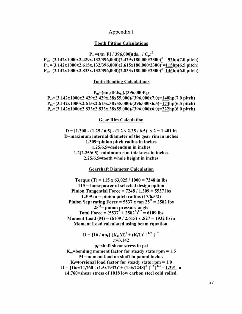
Tooth Pitting Calculations
Pac=(πnpFI / 396,000)(dsac / Cp)2
Pac=(3.142x1000x2.429x.132/396,000)(2.429x180,000/2300)2= 92hp(7.0 pitch) Pac=(3.142x1000x2.615x.132/396,000)(2.615x180,000/2300)2=115hp(6.5 pitch) Pac=(3.142x1000x2.833x.132/396,000)(2.833x180,000/2300)2=146hp(6.0 pitch)
Tooth Bending Calculations
Pat=(πnpdFJsat)/(396,000Pd)
Pat=(3.142x1000x2.429x2.429x.38x55,000)/(396,000x7.0)=140hp(7.0 pitch) Pat=(3.142x1000x2.615x2.615x.38x55,000)/(396,000x6.5)=174hp(6.5 pitch) Pat=(3.142x1000x2.833x2.833x.38x55,000)/(396,000x6.0)=222hp(6.0 pitch)
Gear Rim Calculation
D = [1.308 - (1.25 / 6.5) - (1.2 x 2.25 / 6.5)] x 2 = 1.401 in
D=maximum internal diameter of the gear rim in inches 1.309=pinion pitch radius in inches
1.25/6.5=dedendum in inches 1.2(2.25/6.5)=minimum rim thickness in inches
2.25/6.5=tooth whole height in inches
Gearshaft Diameter Calculation
Torque (T) = 115 x 63,025 / 1000 = 7248 in lbs 115 = horsepower of selected design option
Pinion Tangential Force = 7248 / 1.309 = 5537 lbs 1.309 in = pinion pitch radius (17/6.5/2)
Pinion Separating Force = 5537 x tan 25O = 2582 lbs 25O= pinion pressure angle
Total Force = (55372 + 25822)1/2 = 6109 lbs Moment Load (M) = (6109 / 2.615) x .827 = 1932 lb in
Moment Load calculated using beam equation.
D = {16 / πpt [ (KmM)2 + (KtT)2 ]1/2 }1/3 π=3.142
pt=shaft shear stress in psi Km=bending moment factor for steady state rpm = 1.5
M=moment load on shaft in pound inches Kt=torsional load factor for steady state rpm = 1.0
D = {16/π14,760 [ (1.5x1932)2 + (1.0x7248)2 ]1/2 }1/3 = 1.391 in 14,760=shear stress of 1018 low carbon steel cold rolled.
28
Appendix II
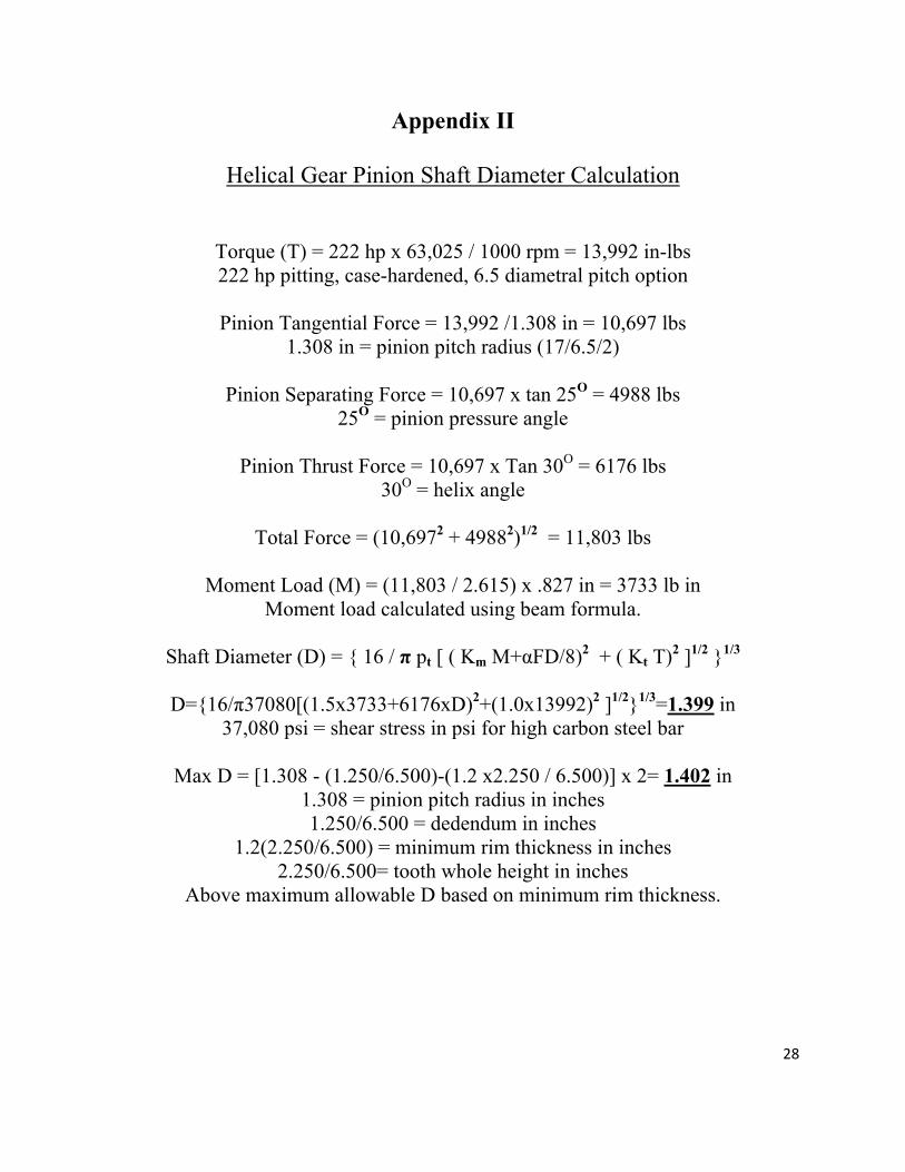
Helical Gear Pinion Shaft Diameter Calculation
Torque (T) = 222 hp x 63,025 / 1000 rpm = 13,992 in-lbs 222 hp pitting, case-hardened, 6.5 diametral pitch option
Pinion Tangential Force = 13,992 /1.308 in = 10,697 lbs
1.308 in = pinion pitch radius (17/6.5/2)
Pinion Separating Force = 10,697 x tan 25O = 4988 lbs 25O = pinion pressure angle
Pinion Thrust Force = 10,697 x Tan 30O = 6176 lbs
30O = helix angle
Total Force = (10,6972 + 49882)1/2 = 11,803 lbs
Moment Load (M) = (11,803 / 2.615) x .827 in = 3733 lb in Moment load calculated using beam formula.
Shaft Diameter (D) = { 16 / π pt [ ( Km M+αFD/8)2 + ( Kt T)2 ]1/2 }1/3
D={16/π37080[(1.5x3733+6176xD)2+(1.0x13992)2 ]1/2}1/3=1.399 in
37,080 psi = shear stress in psi for high carbon steel bar
Max D = [1.308 - (1.250/6.500)-(1.2 x2.250 / 6.500)] x 2= 1.402 in 1.308 = pinion pitch radius in inches 1.250/6.500 = dedendum in inches
1.2(2.250/6.500) = minimum rim thickness in inches 2.250/6.500= tooth whole height in inches
Above maximum allowable D based on minimum rim thickness.