
COURSE FILE - Geethanjali Group of Institutions · COURSE FILE Design of machine ... Syllabus copy...
30
COURSE FILE Design of machine members-ii (Subject Code: 56019) III Year B.Tech. (Mechanical Engineering) II - Semester Prepared by Ravindra Gandhi. Manne DEPARTMENT OF MECHANICAL ENGINEERING GEETHANJALI COLLEGE OF ENGINEERING & TECHNOLOGY Cheeryal (V), Keesara (M), R.R. Dist. - 501 301 (AffiliAted to JNtUH, Approved by AiCte, NeW delHi , ACCREDITED BY NBA) www.geethanjaliinstitutions.com 2015 – 2016
Transcript of COURSE FILE - Geethanjali Group of Institutions · COURSE FILE Design of machine ... Syllabus copy...

COURSE FILE
Design of machine members-ii (Subject Code: 56019)
III Year B.Tech. (Mechanical Engineering) II - Semester
Prepared by Ravindra Gandhi. Manne
DEPARTMENT OF MECHANICAL ENGINEERING GEETHANJALI COLLEGE OF ENGINEERING & TECHNOLOGY
Cheeryal (V), Keesara (M), R.R. Dist. - 501 301 (AffiliAted to JNtUH, Approved by AiCte, NeW delHi, ACCREDITED BY NBA)
www.geethanjaliinstitutions.com
2015 – 2016


GEETHANJALI COLLEGE OF ENGINEERING & TECHNOLOGY
CHEERYAL (V), KEESARA (M), R.R. DIST. 501 301
DEPARTMENT OF MECHANICAL ENGINEERING
INDEX 1. Cover Page
2. Syllabus copy
3. Course objectives and outcomes
4. Instructional Learning Outcomes
5. Course mapping with Programme Outcomes
6. Class Time Table
7. Individual Time Table
8. Micro Plan with dates and closure report
9. Detailed notes
10. Additional/missing topics
11. Tutorial class sheets
12. University previous Question papers
13. Question Bank
14. Assignment Questions
15. Discussion topics
16. Unit-wise objective type questions
17. References, Journals, websites and E-links
18. Quality Control Sheets
19. Students List
20. Group-Wise students list for discussion topics
GEETHANJALI COLLEGE OF ENGINEERING & TECHNOLOGY
CHEERYAL (V), KEESARA (M), R.R. DIST. 501 301
DEPARTMENT OF MECHANICAL ENGINEERING
(Name of the Subject /Lab Course): DESIGN OF MACHINE MEMBERS-II
(JNTU CODE: 56019) Programme: UG
Branch: MECHANICAL ENGINEERING Version No: 01
Year: III Updated on:
Semester: I No. of pages:
Classification status (Unrestricted/Restricted)
Distribution List:
Prepared by:
1) Name : RAVINDRA GANDHI.MANNE 1) Name:
2) Sign. : 2) Sign :
3) Design.: Professor 3) Design:
4) Date : 4) Date :
Verified by: * For Q.C Only.
1) Name : 1) Name : T. Shiva Prasad
2) Sign : 2) Sign :
3) Design : 3) Design. : Professor
4) Date : 4) Date :
Approved by: (HOD)
1) Name : Dr. T. Shiva Prasad
2) Sign :
3) Date :

SYLLABUS COPY
DESIGN OF MACHINE MEMBERS – II
UNIT – I
BEARINGS: Types of Journal bearings – Lubrication – Bearing Modulus – Full and partial bearings –
Clearance ratio – Heat dissipation of bearings, bearing materials – journal bearing design – Ball and
roller bearings – Static loading of ball & roller bearings, bearing life.
UNIT – II
ENGINE PARTS: Connecting Rod: Thrust in connecting rod – stress due to whipping action on
Connecting rod ends – Cranks and Crank shafts, strength and proportions of over hung and center
cranks – Crank pins, Crank shafts. Pistons, Forces acting on piston – Construction Design and
proportions of piston. Cylinder, Cylinder
Liners,
UNIT –III
POWER TRANSMISSIONS SYSTEMS, PULLEYS: Transmission of power by Belt and Rope drives
Transmission efficiencies, Belts – Flat and V types – Ropes - pulleys for belt and rope drives, Materials,
Chain drives
UNIT – VI
SPUR & HELICAL GEAR DRIVES: Spur gears- Helical gears – Load concentration factor – Dynamic
Load factor. Surface compressive strength – Bending strength – Design analysis of spur gears –
Estimation Of centre distance, module and face width, check for plastic deformation. Check for
dynamic and wear Considerations.
UNIT – V
Design of power screws: Design of screw, Square ACME, Buttress screws, design of nut, compound
Screw, Differential screw, ball screw- possible failures. Design of Worm Gears.
TEXT BOOK:
1. Machine Design, V.Bandari Tmh Publishers
2. Machine Design, S MD Jalaludin, Anuradha Publishers
3. Machine Design, Kannaiah/ Scietech.
REFERENCES:
1. Design Data hand Book, S MD Jalaludin, Anuradha Publishers
2. Machine Design / R.N. Norton
3. Data Books : (I) P.S.G. College of Technology (ii) Mahadevan
4. Mech. Engg. Design / JE Shigley
Course Description:
Mechanical design is creating new devices or improving existing ones in an attempt to provide the
\best", or \optimum" design consistent with the constraints of time, money, and safety, as dictated by the
application and the market place. In other words, mechanical design may be de need as an iterative
decision-making process that has as its objective the creation and optimization of a new or improved
mechanical engineering system or device for the fulfilment of a human need or desire, with due regard
for conservation of resources and environmental impact.
Pre-requisites
The trainees should have a basic knowledge Machine design, together with some operational experience
of machine members.
Course Objectives of the Design of Machine Members.
The main objective of any engineering design project is the fulfilment of some human need or
desire. Broadly, engineering may be described as a judicious blend of science and art in which
natural resources, including energy sources, are transformed into useful products, structures, or
machines that benefit humankind.
Science may be defined as any organized body of knowledge. Art may be thought of as a skill or set
of skills acquired through a combination of study, observation, practice, and experience, or by
intuitive capability or creative insight. Thus engineers utilize or apply scientic knowledge together
with artistic capability and experience to produce products or plans for products.
At the end of this subject, the students should be able to understand
Types of loading on machine elements and allowable stresses.
Concept of yielding and fracture.
Different theories of failure.
Construction of yield surfaces for failure theories.
Optimize a design comparing different failure theories.
Instructional learning out Comes :
BELT DRIVES:
At the end of this lesson, the students should be able to understand:
1. Uses and advantages of belt drives
2. Types of belt drives and their nomenclature
3. Relationship between belt tensions
4. Some commonly used design parameters
BEARINGS:
At the end of this lesson, the students should be able to understand:
1. Types of bearings
2. Comparison of bearing friction characteristics
3. Basics of hydrodynamic theory of lubrication
4. Design methods for journal bearings.
ROLLING CONTACT BEARINGS:
At the end of this lesson, the students should be able to understand:
1. About rolling contact bearings
2. Ball bearing and roller bearing
3. Basics definitions of design parameters of rolling contact bearings
4. Selection method for rolling contact bearings.
GEARS: SPUR GEAR, WORM GEAR.
1. Gear tooth profiles, involute profile -basics, Influence of number of teeth and pressure
angle Lecture 4- Analysis of forces on spur, and helical gears
2. Bending and contact stress in gear tooth.
3. Lewise equation for design
4. Gear quality and selection aspects.\
5. Force analysis on bevel and worm gears
6. -Law of gearing-conjugate action and interference in gears
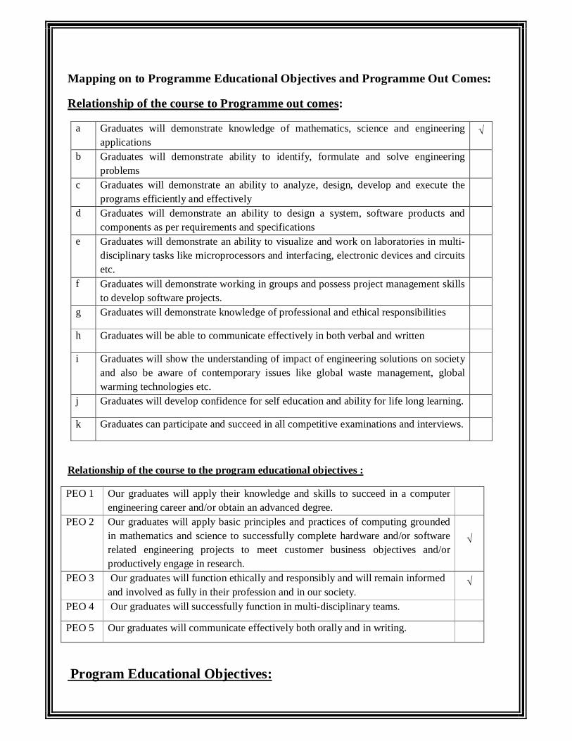
Mapping on to Programme Educational Objectives and Programme Out Comes:
Relationship of the course to Programme out comes:
a Graduates will demonstrate knowledge of mathematics, science and engineering applications
√
b Graduates will demonstrate ability to identify, formulate and solve engineering problems
c Graduates will demonstrate an ability to analyze, design, develop and execute the programs efficiently and effectively
d Graduates will demonstrate an ability to design a system, software products and components as per requirements and specifications
e Graduates will demonstrate an ability to visualize and work on laboratories in multi-disciplinary tasks like microprocessors and interfacing, electronic devices and circuits etc.
f Graduates will demonstrate working in groups and possess project management skills to develop software projects.
g Graduates will demonstrate knowledge of professional and ethical responsibilities
h Graduates will be able to communicate effectively in both verbal and written
i Graduates will show the understanding of impact of engineering solutions on society and also be aware of contemporary issues like global waste management, global warming technologies etc.
j Graduates will develop confidence for self education and ability for life long learning.
k Graduates can participate and succeed in all competitive examinations and interviews.
Relationship of the course to the program educational objectives :
PEO 1 Our graduates will apply their knowledge and skills to succeed in a computer engineering career and/or obtain an advanced degree.
PEO 2 Our graduates will apply basic principles and practices of computing grounded in mathematics and science to successfully complete hardware and/or software related engineering projects to meet customer business objectives and/or productively engage in research.
√
PEO 3 Our graduates will function ethically and responsibly and will remain informed and involved as fully in their profession and in our society.
√
PEO 4 Our graduates will successfully function in multi-disciplinary teams.
PEO 5 Our graduates will communicate effectively both orally and in writing.
Program Educational Objectives:

PEO1: Our graduates will apply their knowledge and skills to succeed in a computer engineering
career and/or obtain an advanced degree.
PEO2: Our graduates will apply basic principles and practices of computing grounded in
mathematics and science to successfully complete hardware and/or software related engineering projects
to meet customer business objectives and/or productively engage in research.
PEO3: Our graduates will function ethically and responsibly and will remain informed and involved
as fully in their profession and in our society.
PEO4: Our graduates will successfully function in multi-disciplinary teams.
PEO5: Our graduates will communicate effectively both orally and in writing.
Outcomes:
a. Graduates will demonstrate knowledge of mathematics, science and engineering applications
b. Graduates will demonstrate ability to identify, formulate and solve engineering problems
c. Graduates will demonstrate an ability to analyse, design, develop and execute the programs
efficiently and effectively
d. Graduates will demonstrate an ability to design a system, software products and components as per
requirements and specifications
e. Graduates will demonstrate an ability to visualize and work on laboratories in multi-disciplinary
tasks like microprocessors and interfacing, electronic devices and circuits etc.
f. Graduates will demonstrate working in groups and possess project management skills to develop
software projects.
g. Graduates will demonstrate knowledge of professional and ethical responsibilities
h. Graduates will be able to communicate effectively in both verbal and written
i. Graduates will show the understanding of impact of engineering solutions on society and also be
aware of contemporary issues like global waste management, global warming technologies etc.
j. Graduates will develop confidence for self education and ability for life long learning.
k. Graduates can participate and succeed in all competitive examinations and interviews.
GEETHANJALI COLLEGE OF ENGINEERING & TECHNOLOGY
CHEERYAL (V), KEESARA (M), R.R. DIST. 501 301
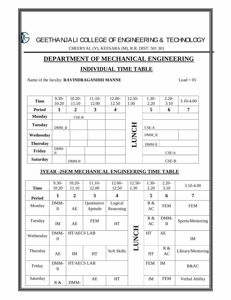
DEPARTMENT OF MECHANICAL ENGINEERING INDIVIDUAL TIME TABLE
Name of the faculty: RAVINDRAGANDHI MANNE Load = 05
Time 9.30-10.20
10.20-11.10
11.10-12.00
12.00-12.50
12.50-1.30
1.30-2.20
2.20-3.10 3.10-4.00
Period 1 2 3 4
LUN
CH
5 6 7 Monday CSE-B Tuesday
DMM_II CSE-A
Wednesday DMM_II
Thursday DMM-II Friday DMM-
II CSE-A
Saturday DMM-II CSE-B 3YEAR -2SEM MECHANICAL ENGINEERING TIME TABLE
Time
9.30-10.20
10.20-11.10
11.10-12.00
12.00-12.50
12.50-1.30
1.30-2.20
2.20-3.10 3.10-4.00
Period 1 2 3 4
LU
NC
H
5 6 7
Monday
DMM-II AE
Quntitative Apttude
Logical Reasoning
R & AC
FEM FEM
Tuesday IM AE
FEM HT
R & AC
DMM-II
Sports/Mentoring
Wednesday
DMM-II
HT/AECS LAB
HT AE IM
Thursday AE IM HT
Soft Skills HT
R & AC
Library/Mentoring
Friday
DMM-II
HT/AECS LAB
FEM IM R&AC
Saturday R & DMM-
AE HT IM FEM Verbal Ability
AC II
Teaching/Learning Methodology
A mixture of lectures, tutorial exercises, and case studies are used to deliver the various topics. Some of
these topics are covered in a problem-based format to enhance learning objectives. Others will be
covered through directed study in order to enhance the students’ ability of “learning to learn.” Some
case studies are used to integrate these topics and thereby demonstrate to students how the various
techniques are inter-related and how they can be applied to real problems in an industry.
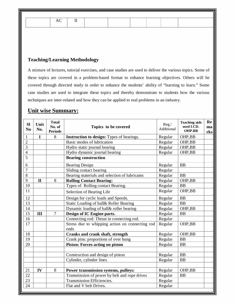
Unit wise Summary:
Sl No
Unit No.
Total No. of
Periods Topics to be covered Reg./
Additional
Teaching aids used LCD. OHP.BB
Remarks
1 I 8 Instruction to design: Types of bearings. Regular OHP,BB 2 Basic modes of lubrication Regular OHP,BB 3 Hydro static journal bearing Regular OHP,BB 4 Hydro dynamic journal bearing Regular OHP,BB 5 Bearing construction
6 Bearing Design Regular BB 7 Sliding contact bearing Regular 8 Bearing materials and selection of lubricants Regular BB 9 II 8 Rolling Contact Bearing: Regular OHP,BB 10 Types of Rolling contact Bearing. Regular BB 11 Selection of Bearing Life Regular OHP,BB
12 Design for cyclic loads and Speeds. Regular BB 13 Static Loading of ball& Roller Bearing Regular BB 14 Dynamic loading of ball& roller bearing Regular OHP,BB 15 III 7 Design of IC Engine parts. Regular BB 16 Connecting rod: Thrust in connecting rod. Regular 17 Stress due to whipping action on connecting rod
ends Regular OHP,BB
18 Cranks and crank shaft, strength Regular OHP,BB 19 Crank pins: proportions of over hung Regular BB 20 Piston: Forces acting on piston Regular BB Construction and design of piston Regular BB Cylinder, cylinder lines Regular BB 21 IV 8 Power transmission systems, pulleys: Regular OHP,BB 22 Transmission of power by belt and rope drives Regular BB 23 Transmission Efficiencies. Regular 24 Flat and V belt Drives. Regular

25 Chain Drives and Materials. Regular OHP,BB 26 V 6 Spur Gear Drives: Regular 27 Load concentration factor Regular OHP,BB 28 VI 8 Helical and Bevel Gear drives: Regular 29 Load concentration factor. Regular 30 Surface compressive strength ,bending strength. Regular OHP,BB 31 Estimation of center distance, module, face width Regular LCD,OHP,BB 32 Check dynamic and wear considerations Regular OHP,BB 33 VII 8 Design of power screws: Regular BB 34 Square ACME, Buttress screws. Regular OHP,BB 35 Design of nut. Regular BB 36 Ball screw possible failures. Regular BB 37 VIII 9 Design of worm Gears: Regular OHP,BB 38 Properties of worm Gears Regular OHPBB 39 Selection of materials. Regular OHP,BB 40 Strength and wear rating of worm gears. Regular OHP,BB
Micro Plan:
Sl. No
Unit No.
Total No. of
Periods Date Topic to be covered in One Lecture
Reg/ Additio
nal
Teaching aids used
LCD/OHP/BB
Remarks
1 I 01 Instruction to design: Regular OHP,BB 2 01 Types of bearings. Regular OHP,BB 3 01 Basic modes of lubrication Regular OHP,BB Tutorial class-1 Regular OHP,BB 4 01 Hydro static journal bearing Regular BB 5 01 Hydro dynamic journal bearing BB 6 01 Bearing construction Regular OHP,BB 7 01 Bearing Design Regular BB
8 01 Tutorial Class-2 Regular OHP,BB Solving University papers Regular BB Assignment test-1 Regular BB 9 01 Rolling Contact Bearing: Addition
al OHP,BB
10 01 Bearing materials and selection of lubricants
BB
11 01 Types of Rolling contact Bearing. BB 12 01 Selection of Bearing Life 13 01 Design for cyclic loads and Speeds. Regular OHP,BB 14 01 Static Loading of ball&Roller Bearing Regular OHP,BB 15 01 Dynamic loading of ball&roller bearing Regular BB 16 01 Numerical problems. Regular OHP,BB Tutorial Class-3 Regular OHP,BB Solving University papers Regular BB Assignment test-2 Regular BB 17 II 01 Design of IC Engine parts. Regular OHP,BB 18 01 Connecting rod:Thrust in connecting
rod. Regular OHP,BB
19 01 Types – Working Principles Regular BB 20 01 Stress due to whipping action on Regular LCD,OHP
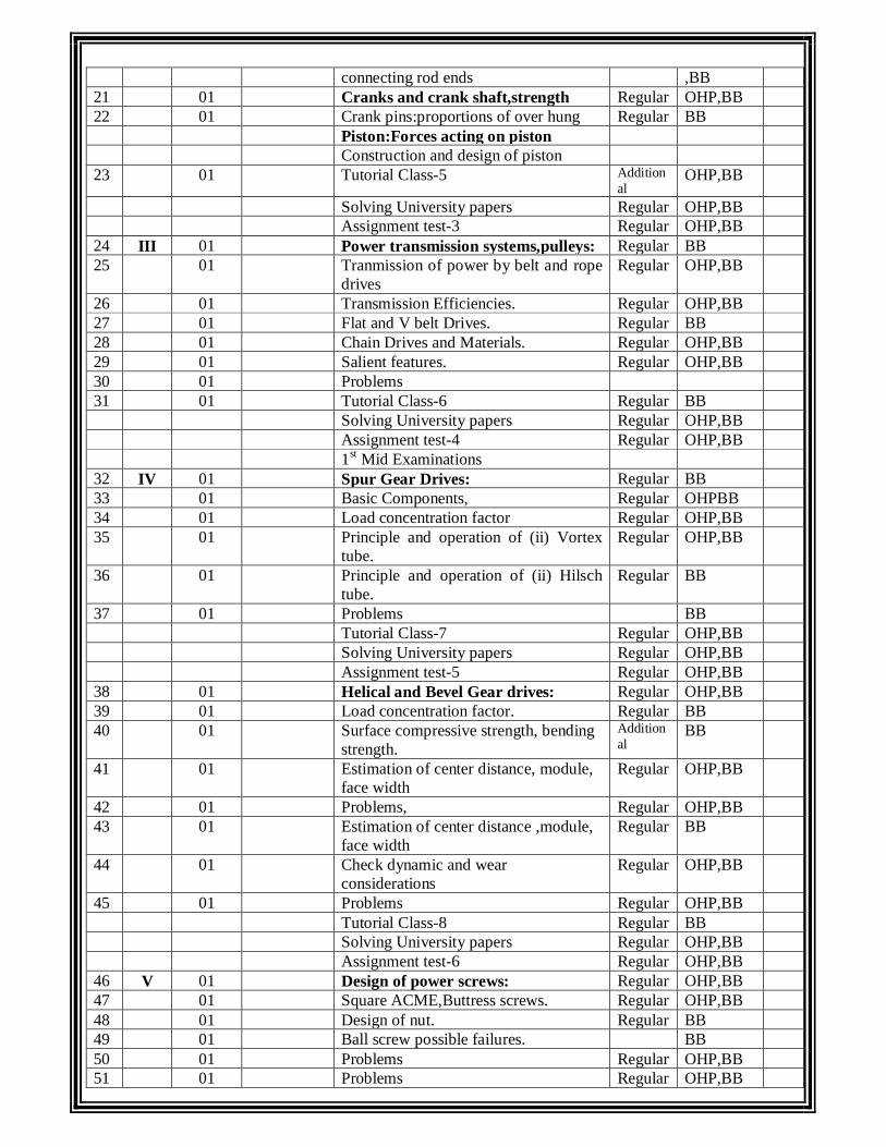
connecting rod ends ,BB 21 01 Cranks and crank shaft,strength Regular OHP,BB 22 01 Crank pins:proportions of over hung Regular BB Piston:Forces acting on piston Construction and design of piston 23 01 Tutorial Class-5 Addition
al OHP,BB
Solving University papers Regular OHP,BB Assignment test-3 Regular OHP,BB 24 III 01 Power transmission systems,pulleys: Regular BB 25 01 Tranmission of power by belt and rope
drives Regular OHP,BB
26 01 Transmission Efficiencies. Regular OHP,BB 27 01 Flat and V belt Drives. Regular BB 28 01 Chain Drives and Materials. Regular OHP,BB 29 01 Salient features. Regular OHP,BB 30 01 Problems 31 01 Tutorial Class-6 Regular BB Solving University papers Regular OHP,BB Assignment test-4 Regular OHP,BB 1st Mid Examinations 32 IV 01 Spur Gear Drives: Regular BB 33 01 Basic Components, Regular OHPBB 34 01 Load concentration factor Regular OHP,BB 35 01 Principle and operation of (ii) Vortex
tube. Regular OHP,BB
36 01 Principle and operation of (ii) Hilsch tube.
Regular BB
37 01 Problems BB Tutorial Class-7 Regular OHP,BB Solving University papers Regular OHP,BB Assignment test-5 Regular OHP,BB 38 01 Helical and Bevel Gear drives: Regular OHP,BB 39 01 Load concentration factor. Regular BB 40 01 Surface compressive strength, bending
strength. Additional
BB
41 01 Estimation of center distance, module, face width
Regular OHP,BB
42 01 Problems, Regular OHP,BB 43 01 Estimation of center distance ,module,
face width Regular BB
44 01 Check dynamic and wear considerations
Regular OHP,BB
45 01 Problems Regular OHP,BB Tutorial Class-8 Regular BB Solving University papers Regular OHP,BB Assignment test-6 Regular OHP,BB 46 V 01 Design of power screws: Regular OHP,BB 47 01 Square ACME,Buttress screws. Regular OHP,BB 48 01 Design of nut. Regular BB 49 01 Ball screw possible failures. BB 50 01 Problems Regular OHP,BB 51 01 Problems Regular OHP,BB

52 01 Problems Regular BB 53 01 Tutorial Class-9 Regular BB Solving University papers Regular BB Assignment test-7 Addition
al OHP,BB
54 01 Design of worm Gears: 55 01 Properties of worm Gears 56 01 Selection of materials. 57 01 Strength and wear rating of worm
gears.
58 01 Design of worm gear. 59 01 Thrust force on gear. 60 01 Problems 61 01 Tutorial Class-8 Regular OHP,BB 62 01 Solving University papers Regular OHP,BB Assignment test-8 Regular BB Mid Test-II Regular OHP,BB
8. Subject Contents 8.1. Synopsis page for each period (62 pages) 8.2. Detailed Lecture notes containing:
a. Ppts b. Ohp slides c. Subjective type questions (approximately 5 t0 8 in no) d. Objective type questions (approximately 20 to 30 in no) e. Any simulations
8.3. Course Review (By the concerned Faculty): (i)Aims (ii) Sample check (iii) End of the course report by the concerned faculty GUIDELINES: Distribution of periods: No. of classes required to cover JNTU syllabus : 60 No. of classes required to cover Additional topics : Nil No. of classes required to cover Assignment tests (for every 2 units 1 test) : 4 No. of classes required to cover tutorials : 2 No. of classes required to cover Mid tests : 2 No of classes required to solve University Question papers : 2
------- Total periods 70
GEETHANJALI COLLEGE OF ENGINEERING & TECHNOLOGY
CHEERYAL (V), KEESARA (M), R.R. DIST. 501 301
SUBJECT NOTES
UNIT-I:
Additional (or) Missing Topics

TUTORIAL CLASS TOPICS
S. No.
Tutorial class Topic Regular / Additional
Teaching aids used LCD/OHP/BB
Date Remarks
1 Hydro static journal bearing Reg BB
2 Hydro Dynamic journal bearing Reg BB
3 Bearing design. Reg BB
4 Bearing construction. Reg OHP
5 Selection of Bearing Life Reg BB
6 Design for cyclic loads and Speeds.
Reg BB
7 Static Loading of ball&Roller Bearing
Reg BB
9 Dynamic loading of ball&roller bearing
Reg BB
10 Cranks and crank shaft, strength Reg BB
11 Crank pins:proportions of over hung
Reg BB
12 Piston:Forces acting on piston Reg BB
13 Construction and design of piston Reg BB
14 Load concentration factor Reg BB
15 Principle and operation of (ii) Vortex tube.
Reg BB
16 Principle and operation of (ii) Hilsch tube.
Reg BB
17 Strength and wear rating of worm gears.
Reg BB
18 Design of worm gear. Reg BB
19 Thrust force on gear. Reg BB
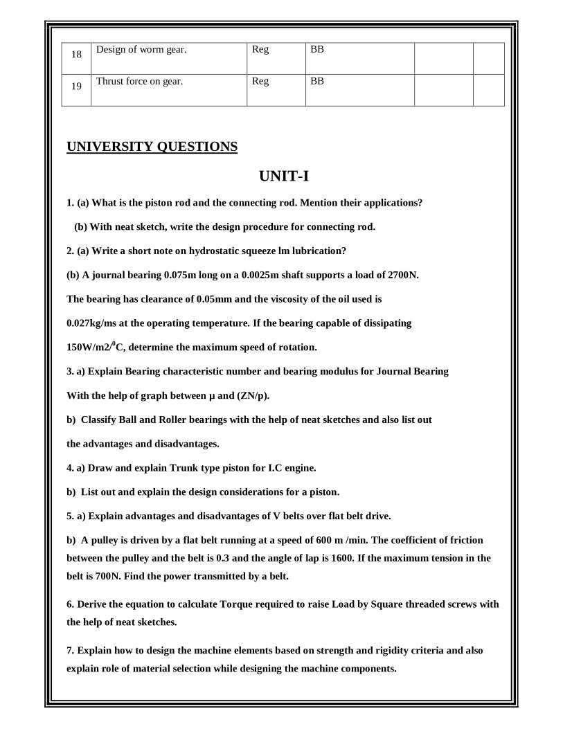
UNIVERSITY QUESTIONS
UNIT-I
1. (a) What is the piston rod and the connecting rod. Mention their applications?
(b) With neat sketch, write the design procedure for connecting rod.
2. (a) Write a short note on hydrostatic squeeze lm lubrication?
(b) A journal bearing 0.075m long on a 0.0025m shaft supports a load of 2700N.
The bearing has clearance of 0.05mm and the viscosity of the oil used is
0.027kg/ms at the operating temperature. If the bearing capable of dissipating
150W/m2/0C, determine the maximum speed of rotation.
3. a) Explain Bearing characteristic number and bearing modulus for Journal Bearing
With the help of graph between µ and (ZN/p).
b) Classify Ball and Roller bearings with the help of neat sketches and also list out
the advantages and disadvantages.
4. a) Draw and explain Trunk type piston for I.C engine.
b) List out and explain the design considerations for a piston.
5. a) Explain advantages and disadvantages of V belts over flat belt drive.
b) A pulley is driven by a flat belt running at a speed of 600 m /min. The coefficient of friction
between the pulley and the belt is 0.3 and the angle of lap is 1600. If the maximum tension in the
belt is 700N. Find the power transmitted by a belt.
6. Derive the equation to calculate Torque required to raise Load by Square threaded screws with
the help of neat sketches.
7. Explain how to design the machine elements based on strength and rigidity criteria and also
explain role of material selection while designing the machine components.

8. What are the advantages of a belt drive?
9. Which one should be the governing pulley to calculate tension ratio?
10. Why the slack side of the belt of a horizontal belt drive is preferable to place on the top side?
11. A crank shaft of the center- crank type is to be designed for a diesel engine developing 7.5kW on brake at 1200r.p.m.The crank shaft is of the forged type and has to carry two y wheels of 500N each on either side of the main bearing. The plane of rotation of each wheel is 100mm from the center line of adjacent main bearing. The maximum load on connecting rod is 35kN.The length of stroke of piston is 160mm and the length of connecting rod 320mm.Maximum torque will be experienced in the crank shaft when the crank turns 300 from the inner dead center position. The maximum permissible stress in crank pin, web and shaft should not exceed 60N/mm2, the safe limit for the bearing stress for the crank pin and the main bearings is 800N/mm2.Design the crank shaft.
12. A ball bearing subjected to a radial load of 4000N is expected to have a satisfactory life of
12000 hours at 720r.p.m with a reliability of 95%.Calculate the dynamic load capacity of the
bearing so that it can be selected from manufacturer's catalogue based on reliability of 95% in a
system. What is the reliability of the complete system?
Assignment Questions for the academic year 2014-2015
UNIT-I
1. (a) What are the characteristics of a good bearing material?
(b) A ball bearing subjected to a radial load of 4000N is expected to have a satisfactory life of
12000 hours at 720r.p.m with a reliability of 95%.Calculate the dynamic load capacity of the
bearing so that it can be selected from manufacturer's catalogue based on reliability of 95% in a
system. What is the reliability of the complete system?
2.. Highlight friction characteristics of bearings.
3. . Can a block moving over a constant height fluid film carry load?
4. Broadly, what are the types of bearings?
UNIT-2

1.(a)Write a short note on hydrostatic squeeze lm lubrication?
(b) A journal bearing 0.075m long on a 0.0025m shaft supports a load of 2700N.The bearing has
clearance of 0.05mm and the viscosity of the oil used is 0.027kg/ms at the operating temperature.
If the bearing capable of dissipating 150W/m2/0C, determine the maximum speed of rotation.
2.. Highlight friction characteristics of bearings.
3.. Can a block moving over a constant height fluid film carry load?
4. What is Sommerfeld number? What importance it has in context of journal
bearing design?
UNIT-3
1.A crank shaft of the center- crank type is to be designed for a diesel engine developing 7.5kW on
brake at 1200r.p.m.The crank shaft is of the forged type and has to carry two y wheels of 500N
each on either side of the main bearing. The plane of rotation of each wheel is 100mm from the
center line of adjacent main bearing.The maximum load on connecting rod is 35kN.The length of
stroke of piston is 160mm and the length of connecting rod 320mm.Maximum torque will be
experienced in the crank shaft when the crank turns 300 from the inner dead center position. The
maximum permissible stress in crank pin, web and shaft should not exceed 60N/mm2, the safe
limit for the bearing stress for the crank pin and the main bearings is 800N/mm2.Design the crank
shaft.
2.Write a design procedure on the following with suitable expressions
(a) Piston head
(b) Piston rings
(c) Piston barrel
(d) Piston skirt
(e) Piston pin.
UNIT-4
1.A CI flat pulley transmits 20kW at a sped of 560 rpm. The pulley overhangs the nearest bearing by
200mm. Assuming the ratio of the belt tension as 2, Determine
(a) Shaft diameter

(b) Pulley diameter and Cross section of eight arms.
A lathe has two flat, CI slide ways of equal width and height half the width. While
turning a 100 mm diameter work piece, the tangential, radial and axial components of the cutting
force were found to be Px=1200N, Py =1300N and Pz =3000Nrespectively . Calculalte the lathe
slide ways width assuming suitable values. Castiron slide ways can with stand a maximum
pressure of 2500 kN/m2.
UNIT-5
1.Why dynamic load is induced in the gear teeth? Explain the procedure of designing the dynamic
load using Buckingham equation.
2. Design a pair of spur pinion and gear made of cast steel and CI respectively .The diameter of
pinion is 140mm and it transmits 30kW at 1250rpm. The gear ratio 3:1 and teeth are 200 full
depth involute. [8+8].
3. What are the causes of failure of gear tooth?
4. Design a pair of spur gears with stub teeth to transmit 55kW from 175 mm pinion running at
2500 r.p.m. to a gear running at 1500 r.p.m. Both the gears are made of steel having B.H.N 260.
Approximate the pitch by means of Lewis equation and then adjust the dimensions to keep within
the limits set by the dynamic load and wear equation
UNIT-6
1.A pair of straight teeth spur gears is to transmit 40kW when the pinion rotates at 300rpm. The
velocity ratio is 1:5. The allowable static stresses for the pinion and gear materials are 120MPa
and 100MPa respectively. The pinion has 15 teeth and its face width is 16 times the module.
Determine the Module; face width and Pitch circle diameters of both the pinion and the gear from
the stand point of strength only, taking into consideration the e
ect of the dynamic loading.The tooth form factor y can be taken as y= 0.154-0.912/no.of teeth and the velocity factor C v = 3/ (3+v), where v is in m/s.
2. What is rating life of a rolling contact bearing?
3. Why determination of equivalent radial load is necessary?
UNIT-7
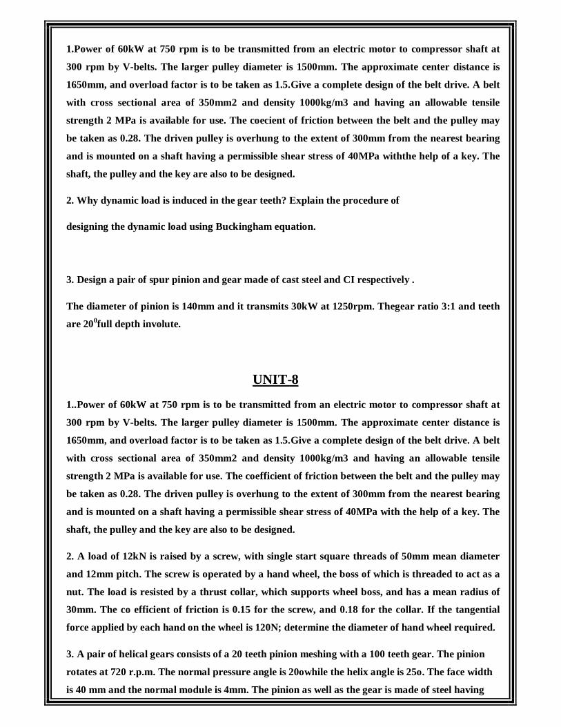
1.Power of 60kW at 750 rpm is to be transmitted from an electric motor to compressor shaft at
300 rpm by V-belts. The larger pulley diameter is 1500mm. The approximate center distance is
1650mm, and overload factor is to be taken as 1.5.Give a complete design of the belt drive. A belt
with cross sectional area of 350mm2 and density 1000kg/m3 and having an allowable tensile
strength 2 MPa is available for use. The coecient of friction between the belt and the pulley may
be taken as 0.28. The driven pulley is overhung to the extent of 300mm from the nearest bearing
and is mounted on a shaft having a permissible shear stress of 40MPa withthe help of a key. The
shaft, the pulley and the key are also to be designed.
2. Why dynamic load is induced in the gear teeth? Explain the procedure of
designing the dynamic load using Buckingham equation.
3. Design a pair of spur pinion and gear made of cast steel and CI respectively .
The diameter of pinion is 140mm and it transmits 30kW at 1250rpm. Thegear ratio 3:1 and teeth
are 200full depth involute.
UNIT-8
1..Power of 60kW at 750 rpm is to be transmitted from an electric motor to compressor shaft at
300 rpm by V-belts. The larger pulley diameter is 1500mm. The approximate center distance is
1650mm, and overload factor is to be taken as 1.5.Give a complete design of the belt drive. A belt
with cross sectional area of 350mm2 and density 1000kg/m3 and having an allowable tensile
strength 2 MPa is available for use. The coefficient of friction between the belt and the pulley may
be taken as 0.28. The driven pulley is overhung to the extent of 300mm from the nearest bearing
and is mounted on a shaft having a permissible shear stress of 40MPa with the help of a key. The
shaft, the pulley and the key are also to be designed.
2. A load of 12kN is raised by a screw, with single start square threads of 50mm mean diameter
and 12mm pitch. The screw is operated by a hand wheel, the boss of which is threaded to act as a
nut. The load is resisted by a thrust collar, which supports wheel boss, and has a mean radius of
30mm. The co efficient of friction is 0.15 for the screw, and 0.18 for the collar. If the tangential
force applied by each hand on the wheel is 120N; determine the diameter of hand wheel required.
3. A pair of helical gears consists of a 20 teeth pinion meshing with a 100 teeth gear. The pinion
rotates at 720 r.p.m. The normal pressure angle is 20owhile the helix angle is 25o. The face width
is 40 mm and the normal module is 4mm. The pinion as well as the gear is made of steel having

ultimate strength of 600MPa and heat treated to a surface hardness of 300B.H.N. The service
factor and factor of safety are 1.5 and 2 respectively. Assume that the velocity factor accounts for
the dynamic load and calculate the power transmitting capacity of the gears.
UNIT WISE OBJECTIVE QUESTIONS
UNIT-1
1. The number of starts on the worm for a velocity ratio of 40 should be [ ]
A) Single B) Double C) Triple D) quadruple
2. The Axial thrust on the worm (WA) is given by [ ]
A) WA=WTTan ΦB) WA=WT/Tan Φ C) WA=WTTan λD) WA=WT/ Tan λ
3. A Screw is specified by [ ]
A) Nominal diameter B) minimum diameter X Length
C) Major diameter X Length D) mean diameter X pitch
4. The initial contact in helical gears is [ ]
A) point contact B) line contact C)Surface contact D) none of the above.
5. The backlash for spur gears depends upon [ ]
A) Module B) pitch line velocity C) Tooth profile D) both (A) and (B.
UNIT-2
1. Lewis equation in spur gears is applied [ ]
A) Only to the pinion B) Only to the gear C) to stronger portion of the pinion or gear D) to weaker portion of the pinion or gear.
2. Longer Helix angles in opposite hand helical gears result in [ ]
A) Smooth and quiet operation B) strong teeth
C) Noisy operation and weaker teeth D) Noisy operation and stronger teeth.

3. If the number of teeth on two bevel gears in mesh is30 and 60, then the cone pitch angle of the pinion
Will be [ ]
A) Tan-1(2) B) Tan-1(0.5) C) Sin-1(0.5) D) Sin -1(1.5).
UNIT-3
1.The allowable static stress for steel gears in approximately _______________ of the ultimate tensile stress.
2. The design of spur gear is safe if the static tooth load should be _____________the dynamic load
3. In helical gears, the right hand helices on one gear will mesh _____________helices on the other gear
4. In bevel gears the velocity ratio is VR then the Pitch angle for the gear is _______________.
5. The worm gears are widely used for transmitting power at ____________velocity ratios between nonintersecting shafts.
6. A screw jack has square threads and the lead angle of the thread Is α. the screw jack will be self-locking when the coefficient of friction (µ) is _______________.
UNIT-4
1. A screw is said to be over hauling screw, if it’s efficiency is _______________.
2. If αdenotes the lead angle and Φis the angle of the friction, then the efficiency of the Screw is _____________.
3. If the lead angle of a worm is 20⁰, then helix angle will be___________________.
4. in Zero bevel gears, the axes are_________________.
5. For a bevel gear having the pitch angle θ, the ratio of formative number of teeth (TE) to actual number of teeth (T)is [ ]
A) 1/sin θ B) 1/cos θ C) 1/Tan θ D) sin θcos θ
UNIT-5
1. The initial contact in helical gears is [ ]

A) Point contact B) line contact C) Surface contact D) none of the above.
2. Oil in journal bearing should be applied at the point where load is [ ]
(A) Nil or lightest (B) Maximum (C) Average D) Any one of the above
3. The usual clearance provided in hydro-dynamic bearing per mm of diameter of shaft is [ ]
(A) 0.1 micron (B) 0.01 micron (C) 1 micron (D) 10 micron
5. In standard taper roller bearings the angle of taper of outer race ways is [ ]
(A) 50 (B) 80 (C) 150 (D) 250
UNIT-6
1. The rolling contact bearings are known as [ ]
(A) Thick lubricated bearings (B) Plastic bearings
(C) Thin lubricated bearings (D) Anti friction bearings.
2. The piston pin bearings in heavy duty diesel engines are
(A) Needle rollers bearings (B) Tapered roller bearings (C) Spherical roller bearings (D) Cylindrical roller bearings.
3. The Rocker arm is used to actuate the inlet and exhaust valves motion as directed by the [ ]
(A) Cam and Followers (B) Crank (C) Crank shaft (D) Piston
4. The standard angle between the sides of the V belt is [ ]
(A) 250 (B) 300 (C) 400 (D) 450.
5. Which one of the following is a Positive Drive? [ ]
(A) Crossed flat belt drive (B) RopeDrive (C) V Belt drive (D) Chain drive.
UNIT-7
1. Bearing characteristics number is more than bearing modules (K) then

Bearing will operate with ________________
2. If the ratio of the length to the diameterl/d is less than one then the bearing is
Called _______________.
3. The ratio of average life and rating life of the ball bearing is _______________.
4 Life of the roller bearing is given in million no. of cycles by ________________
5. For high speed engines a rocker arm of __________________ should be used.
UNIT-8
1. The tension in the slack side of the belt is____ the tension in the tight side of the belt.
2. The chain drives transmits ___________ power as compared to belt drive.
3. The V belts are particularly suitable for ____________________ drives.
4. Belt slip may occur due to __________________.
5. The side thrust on the cylinder liner is usually taken as _______________ of the
Maximum gas load on the piston.

Sources of Information
I.7.1. Text books: 1. Khurmi, R.S. and Gupta J.K., Text book on Machine Design, Eurasia
Publishing House, New Delhi. 2. Sharma, C.S. and Purohit Kamalesh, Design of Machine Elements,
Prentice Hall of India, New Delhi, 2003.
I.7.2. Reference Text Books: 1. V.Maleev and James B. Hartman , Machine Design, CBS Publishers And
Distributors.3rd Edition. 1983. 2. J.E Shigley and C.R Mischke , Mechanical Engineering Design , McGraw
Hill Publication, 5th Edition. 1989. 3. M.F Spotts, Design of Machine Elements, Prentice Hall India Pvt. Limited,
6th Edition, 1991.
1.7.3. Websites: 1. http://www.gmrit.org/resources/syllabus_me.pdf
2. NPTEL Resources
SUBJECT NAME: REFRIGERATION AND AIR CONDITIONING
SUBJECT CODE: 56018.
SCOPE:
The course aims to provide deeper knowledge, a wider scope and improved understanding of the study
of motion and the basic principles of mechanics and strength of materials. It is a concept based subject
and it needs the application capabilities of the concepts on the part of the students.
EVALUATION SCHEME: PARTICULAR WEIGHTAGE MARKS
End Examinations 75% 75 Three Sessionals 20% 20 Assignment 5% 5

TEACHER'S ASSESSMENT(TA)* WEIGHTAGE MARKS *TA will be based on the Assignments given, Unit test Performances and Attendance in the class for a particular student.
QUALITY SHEETS
STUDENT LIST:
GEETHANJALI COLLEGE OF ENGINEERING & TECHNOLOGY
CHEERYAL (V), KEESARA (M), R.R. DIST. 501 301
DEPARTMENT OF MECHANICAL ENGINEERING
GROUP WISE STUDENTS LIST FOR DISCUSSION TOPICS
S.No Group No Hall Ticket No STUDENT NAME
1 1
2 2
3 3
4 4

5 5
6 6
7 7
8 8
9 9
10 10