Course: EE 1103 onic Subject: Basic Electrical Engineering ...
35
Course: EE 1103 Subject: Basic Electrical Engineering Topic: Phasor Algebra – Cont’d Edited and Presented by- Dr. Mohiuddin Ahmad Dept. of EEE, KUET, Khulna-9203, Bangladesh Department of Electrical and Electronic Engineering
Transcript of Course: EE 1103 onic Subject: Basic Electrical Engineering ...
Course: EE 1103
Subject: Basic Electrical Engineering
Topic: Phasor Algebra – Cont’d
Edited and Presented by-
Dr. Mohiuddin Ahmad Dept. of EEE, KUET, Khulna-9203,
Bangladesh
D
ep
artm
en
t o
f El
ect
rica
l an
d E
lect
ron
ic E
ngi
ne
eri
ng

Contents of the Topic
Phasor Relationships For Circuit Elements
Impedance expressed in polar form
Impedance expressed in Cartesian form
Addition and subtraction of voltages and currents
Power calculations employing complex forms
Reactive volt-ampere calculations employing complex
forms
Conjugate method of calculating real and reactive
power
Mathematical problems

Reference Books
References
1. Alternating current circuits – Kerchner & Corcoran
2. Fundamentals of Electric Circuit – Alexander & Sadiku
3. Electrical Circuit analysis - Boylestad
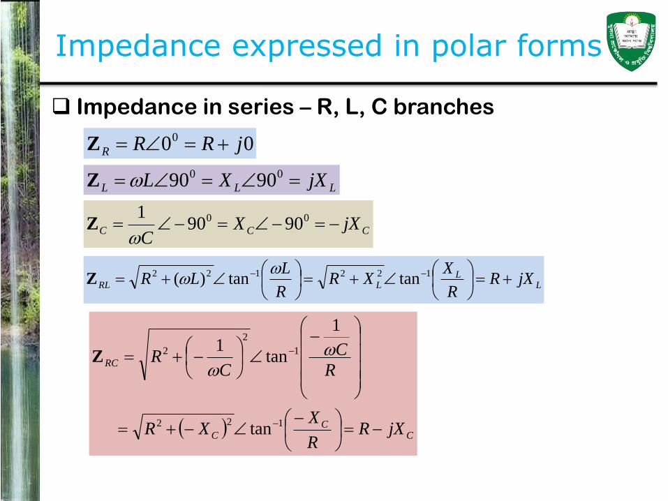
Impedance expressed in polar forms
Impedance in series – R, L, C branches
000 jRRR Z
CC
C
RC
jXRR
XXR
R
C
CR
122
1
2
2
tan
1
tan1
Z
LLL jXXL 00 9090Z
CCC jXXC
00 90901
Z
LL
LRL jXRR
XXR
R
LLR
122122 tantan)(
Z
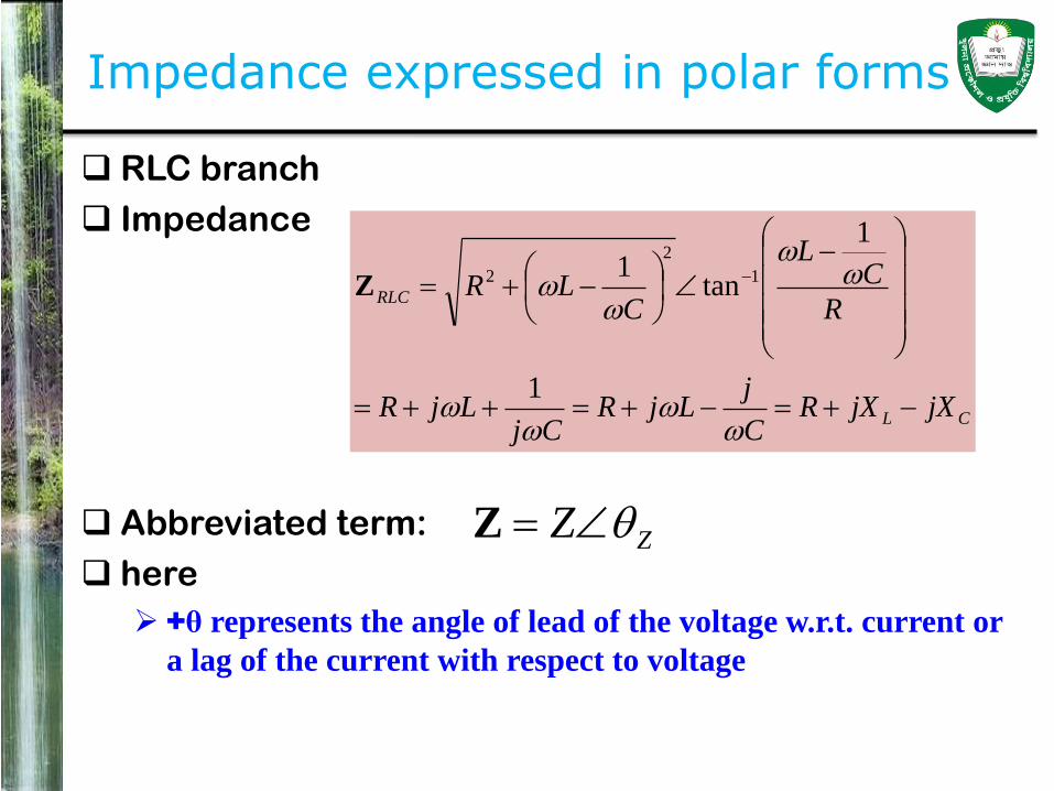
Impedance expressed in polar forms
RLC branch
Impedance
Abbreviated term:
here
+θ represents the angle of lead of the voltage w.r.t. current or
a lag of the current with respect to voltage
CL
RLC
jXjXRC
jLjR
CjLjR
R
CL
CLR
1
1
tan1 1
2
2Z
ZZ Z

Impedance expressed in polar forms
Phasor voltage
Impedance
Resulting current,
vV V
zv
z
v
Z
V
Z
V
I
zZ Z

Impedance expressed in Cartesian forms
The Cartesian form of the impedance function of a
given RLC branch or circuit is, in general
R is the equivalent resistance of the branch or circuit
with respect to the terminals considered
(XL – XC) is the equivalent reactance of the branch or
circuit with respect to the terminals considered.
)( CL XXjR Z

Phasor Diagram
Phasor diagram of an RLC circuit

Phasor Diagram
Phasor diagram of an RLC circuit
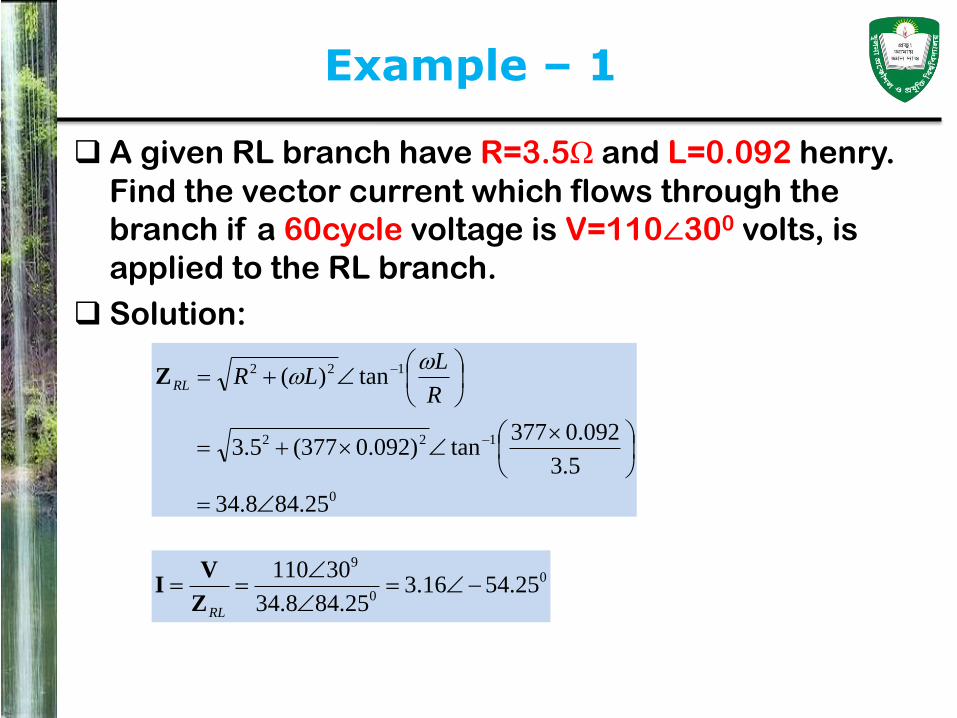
Example – 1
A given RL branch have R=3.5Ω and L=0.092 henry.
Find the vector current which flows through the
branch if a 60cycle voltage is V=110∠300 volts, is
applied to the RL branch.
Solution:
0
122
122
25.848.34
5.3
092.0377tan)092.0377(5.3
tan)(
R
LLRRL
Z
0
0
9
25.5416.325.848.34
30110
RLZ
VI

Example – 1
Vector representation

Example – 2
An RLC series branch consists of R=12.9Ω and L=0.056 henry,
and C=78μF. (a) What is the vector or complex impedance of the
RLC branch? (b) If a 60-cycles vector current I=10∠300 amperes
flows through the branch, find the vector voltage V across the
terminals of series branch. Draw a vector diagram illustrating
the vector positions of V and I and the magnitude of phase
angle V with respect to I.
Solution: (a)
ohms 4524.18 9.12
341.21tan341.219.12
9.12
1078377
1056.0377
tan1078377
1056.03779.12
1
tan1
0122
61
2
6
2
1
2
2
R
CL
CLRRLC
Z

Example – 2
An RLC series branch consists of R=12.9Ω and L=0.056 henry, and C=78μF. (a) What is the
vector or complex impedance of the RLC branch? (b) If a 60-cycles vector current I=10∠300
amperes flows through the branch, find the vector voltage V across the terminals of series
branch. Draw a vector diagram illustrating the vector positions of V and I and the
magnitude of phase angle V with respect to I.
Solution: (b) In Rectangular form
(C) Vector diagram – Draw it by yourself
ohms 341.219.12 jjjXjXR CLRLC Z
volts154.182)4524.18)(3010( 000 RLCIZV

Example – 3
Example: The terminal of an a-c generator which has an internal resistance of 2 –ohm and an equivalent internal inductive reactance of 6-ohms are connected to an RLC series branch, the R of which is 10 ohms, the ωL is 20 ohms, and the 1/ωC of which is 40 ohms. If the magnitude of the internally generated emf is 500 volts, find the current that flows in the series circuit and the terminal voltage of the generator.
Solution:
Internal impedance of the generator
Total impedance of the series circuit
ohms 6.7132.6 ohms 62 0 jgZ
ohms 4.4944.18ohms 1412
40201062
0
j
jjjRLCgtotal ZZZ

Example – 3
Example: The terminal of an a-c generator which has an internal resistance of 2 –ohm and an equivalent internal inductive reactance of 6-ohms are connected to an RLC series branch, the R of which is 10 ohms, the ωL is 20 ohms, and the 1/ωC of which is 40 ohms. If the magnitude of the internally generated emf is 500 volts, find the current that flows in the series circuit and the terminal voltage of the generator.
Solution:
Generated emf
Current flows in the series circuit
Terminal voltage of the generator
volts05000500 0 jg E
amperes 4.491.274.4944.18
0500 0
0
0
total
gI
Z
E
volts14606j147588.3
volts)6.7132.6()4.491.27(0500
0
000
ggg IZEV
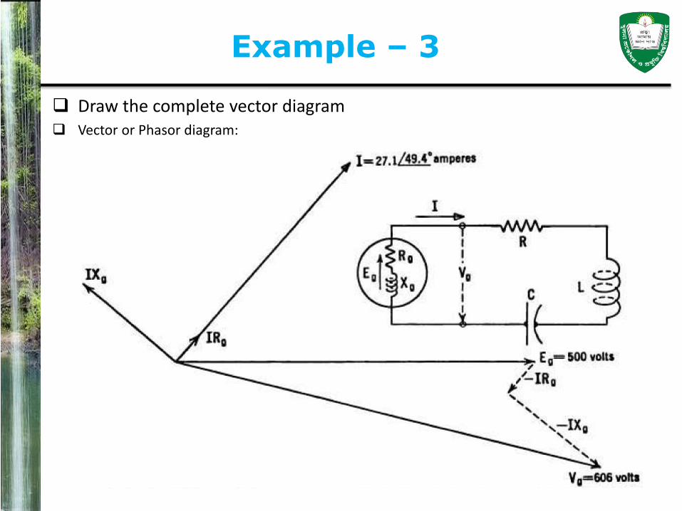
Example – 3
Draw the complete vector diagram Vector or Phasor diagram:
Example – 3
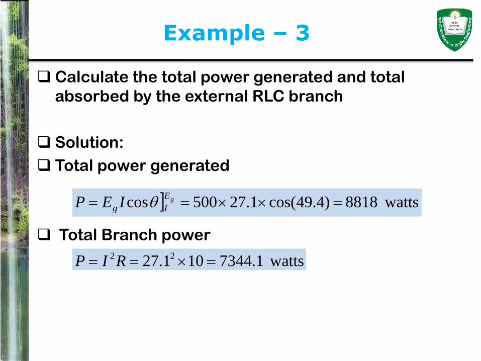
Calculate the total power generated and total
absorbed by the external RLC branch
Solution:
Total power generated
Total Branch power
watts8818)4.49cos(1.27500cos gE
Ig IEP
watts1.7344101.27 22 RIP

Additions and Subtraction of voltages and Currents
Complex expressions for voltages and currents
specify both the magnitudes and relative phase
positions of these quantities.
1. Voltage drops in series may be added to obtain the
combined voltage drop of the series elements
considered.
If the combined voltage drop and one component are
known, the remaining voltage drop may be determined
by subtracting the component in question from the
combined voltage drop.

Additions and Subtraction of voltages and Currents
2. Generated emf'e connected in additive or
subtractive aeries may be added or subtracted,
depending upon the relative polarities of the terminal
which are joined together to found the series
connection.
Series connections of generated emf’s will be
considered in more detail when poly-phase systems
are studied.
3. Two or more currents flowing away from a junction
may be added to find the current flowing toward the
junction, or vice versa.

Circuit Directions of voltages and currents
Average power absorbed by a branch
V is the magnitude of the voltage drop across the
branch or circuit.
I is the magnitude of the current flowing through the
branch or circuit in the same circuit direction as that
which has been taken for the + V direction.
is the angle of lag (or lead) of I with respect to V.
• In a normal dissipative type of branch or circuit, θ will not
be as great as ±900.
VIVIP cos

Circuit Directions of voltages and currents
Similarly, average power generated by a generating
device
E is the magnitude of the generated voltage.
I is the magnitude of the current flowing through the
branch or circuit in the same circuit direction as that
which has been taken for the + E direction.
is the angle of lag (or lead) of I with respect to E.
• In case, the generating device actually delivering power,
θ is less than 900.
EIEIP cos

Power Calculations Employing Complex Forms
Power Expression – absorbed power
VIcosVIP
ivvi
IVIV
IVIV
VIVI
VI
VI
VIP
iviv
iviv
iviv
iviv
iviv
iv
)sin)(sin()cos)(cos(
sinsincoscos
sinsincoscos
)sinsincos(cos
)sinsincos(cos
)cos(
i
v
i
v
Ii
Vv
Ii
Vv
sin
sin
cos
cos
Power Calculations Employing Complex Forms
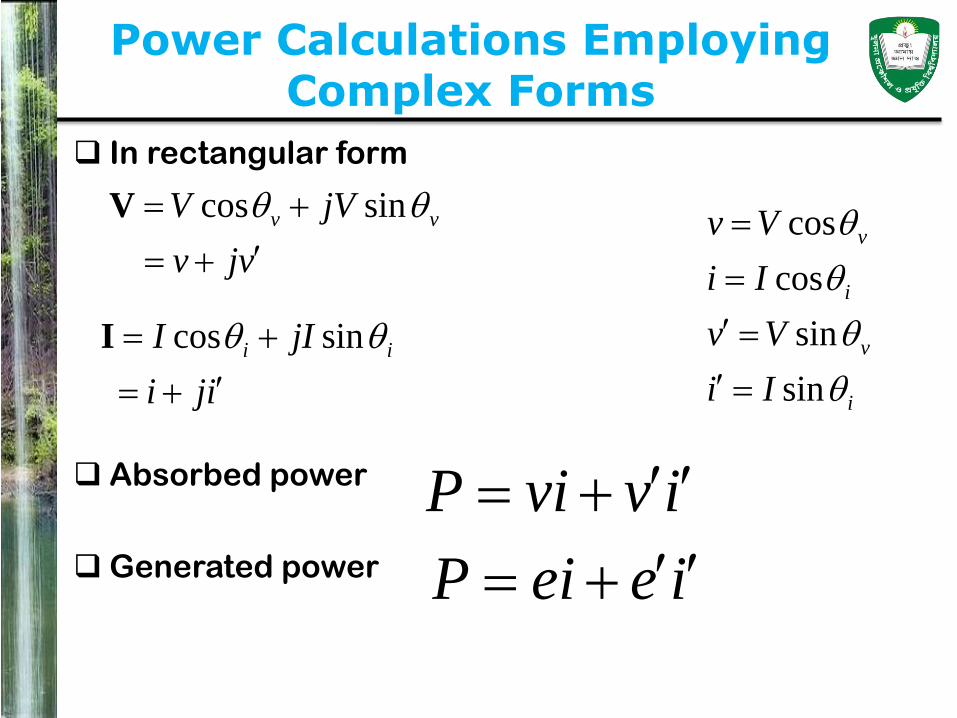
In rectangular form
Absorbed power
Generated power
vjv
jVV vv
sincos V
i
v
i
v
Ii
Vv
Ii
Vv
sin
sin
cos
cos
iji
jII ii
sincos I
ivviP
ieeiP

Power Calculations Employing Complex Forms
Power Expression – Generated power
EIcosEIP
ieei
IEIE
IEIE
EIEI
EI
EI
EIP
iviv
iviv
iviv
iviv
iviv
iv
)sin)(sin()cos)(cos(
sinsincoscos
sinsincoscos
)sinsincos(cos
)sinsincos(cos
)cos(
i
v
i
v
Ii
Ee
Ii
Ee
sin
sin
cos
cos
Example – 4
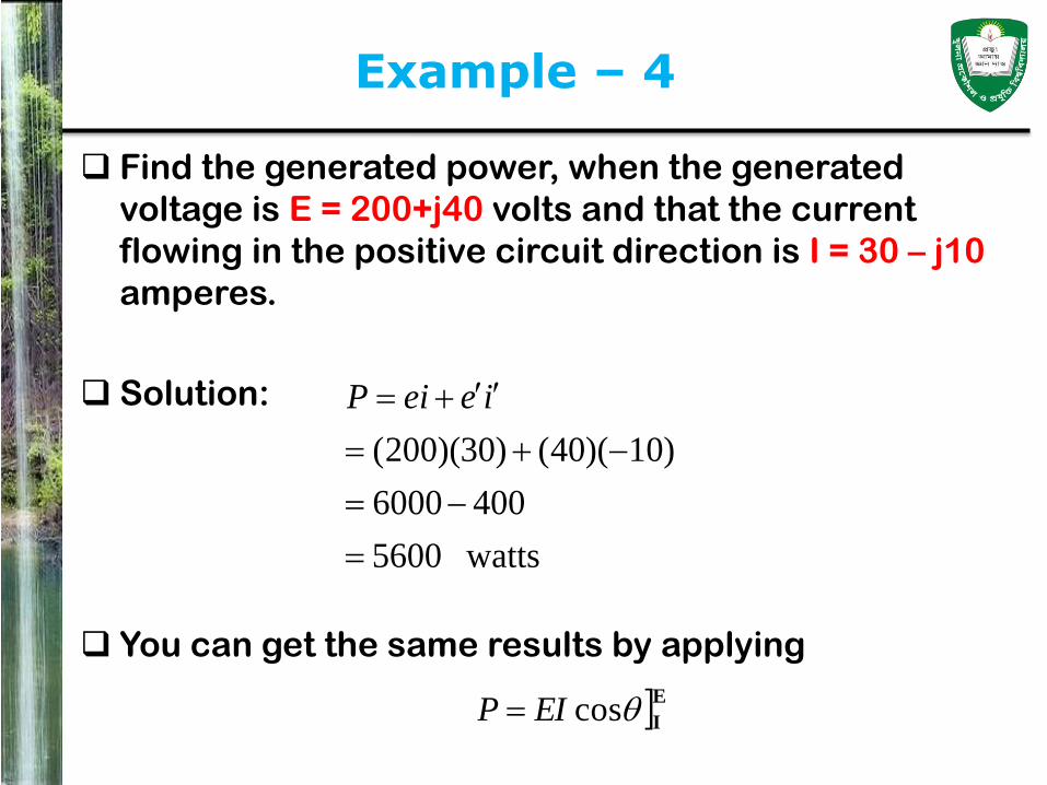
Find the generated power, when the generated
voltage is E = 200+j40 volts and that the current
flowing in the positive circuit direction is I = 30 – j10
amperes.
Solution:
You can get the same results by applying
watts5600
4006000
)10)(40()30)(200(
ieeiP
EIcosEIP

Reactive Volt-ampere Calculations Employing Complex Forms
Volt-ampere calculations
VIsinVIPX
ivivP
IVIV
IVIV
VIVI
VI
VIP
X
iviv
iviv
iviv
iviv
ivX
)sin)(cos()cos)(sin(
sincoscossin
sincoscossin
)sincoscos(sin
)sin(
i
v
i
v
Ii
Vv
Ii
Vv
sin
sin
cos
cos

Reactive Volt-ampere Calculations Employing Complex Forms
Example – 5
If V= 200∠300 =173.2+j100 volts and I= 10∠600
=5+j8.66 amperes, find the real power, the reactive
volt-amperes, and the total voIt-amperes involved.
Solutions:
Real-power,
Reactive volt-ampere,
Volt-ampere,
watts1732866866
)66.8)(100()5)(2.173(
ivviP
vars1500500)66.8)(2.173()5)(100( ivivPX
amperes- volt2000)1000()1732( 22 S
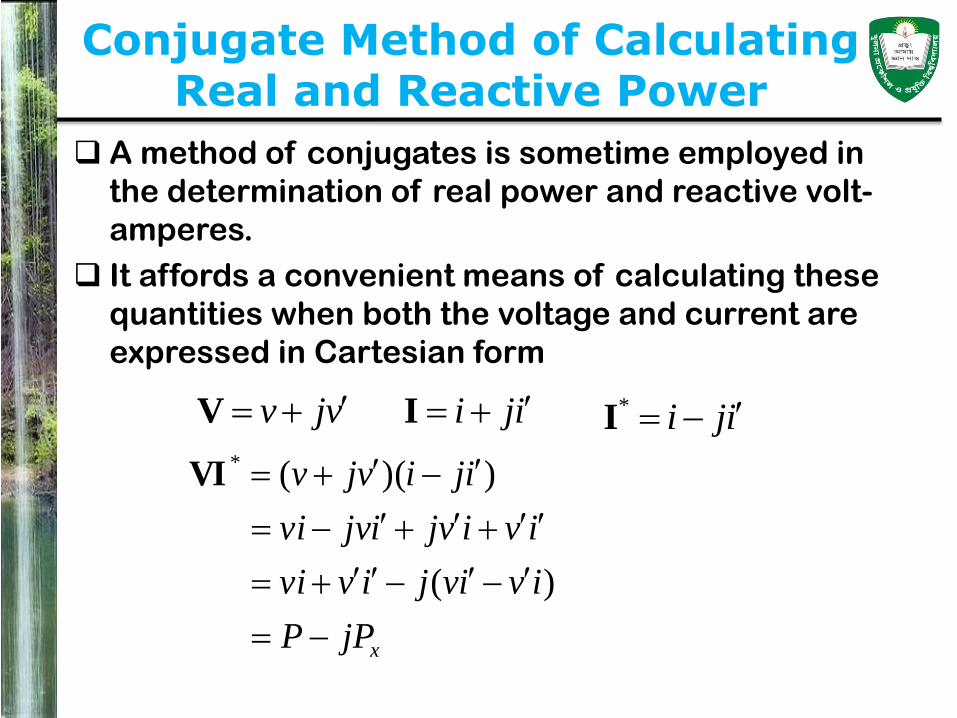
Conjugate Method of Calculating Real and Reactive Power
A method of conjugates is sometime employed in
the determination of real power and reactive volt-
amperes.
It affords a convenient means of calculating these
quantities when both the voltage and current are
expressed in Cartesian form
iji Ivjv V iji *I
xjPP
ivivjivvi
ivivjijvvi
ijivjv
)(
))((*VI

Conjugate Method of Calculating Real and Reactive Power
Example – 6
If V= 173.2+j100 volts and I= 5+j8.66 amperes, find
the real power, the reactive volt-amperes, and the
total voIt-amperes by the method of conjugates.
Solutions:
Volt-ampere,
Real-power,
Reactive volt-ampere
Here, + sign indicates capacitive vars when the
conjugates of the voltage is used.
Volt-ampere,
100017325008661500866
)66.85)(100173(
jjj
jjPva
amperes- volt2000)1000()1732( 22 S
vars1000XP
watts1732P
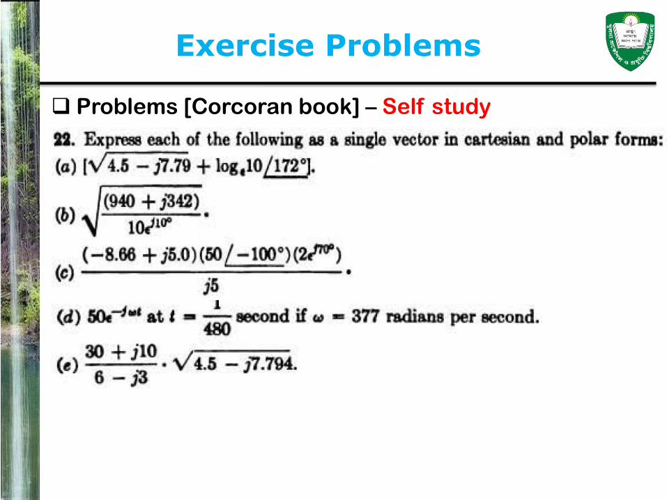
Exercise Problems
Problems [Corcoran book] – Self study
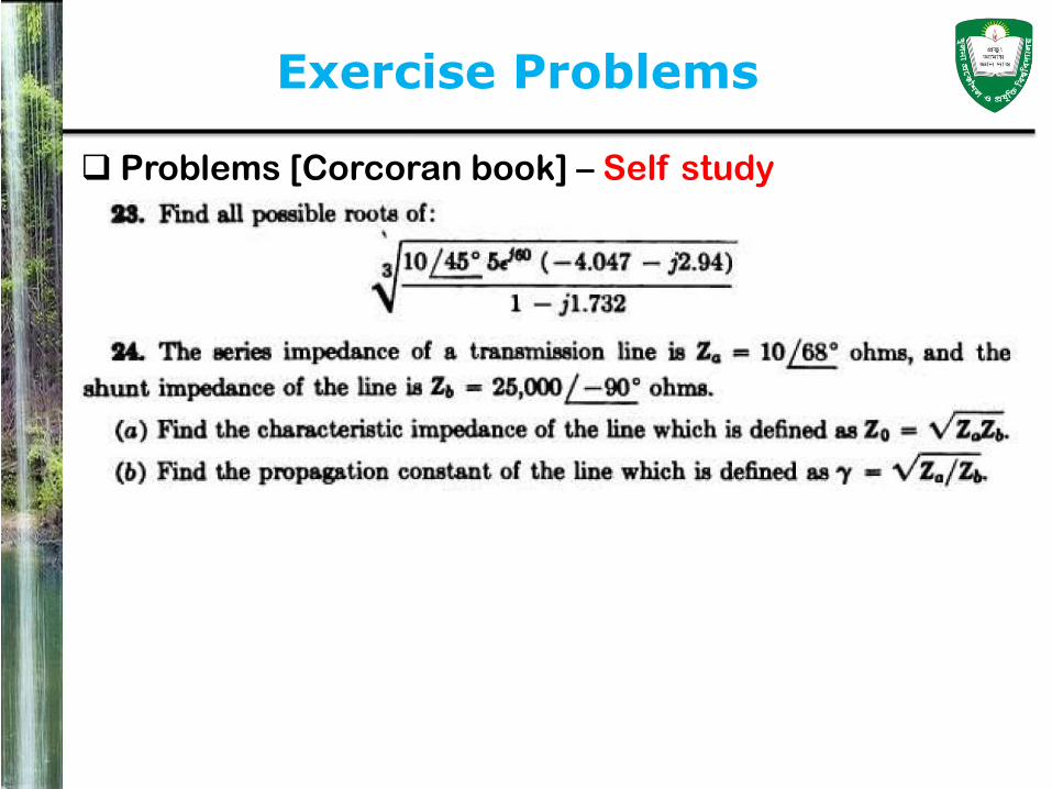
Exercise Problems
Problems [Corcoran book] – Self study
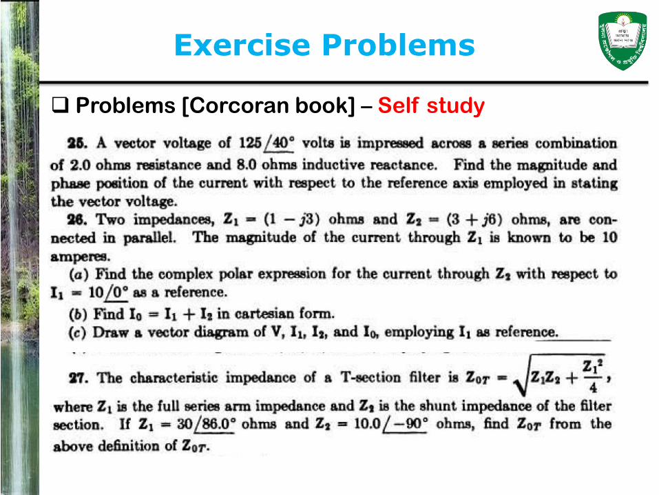
Exercise Problems
Problems [Corcoran book] – Self study

Exercise Problems
Problems [Corcoran book] – Self study
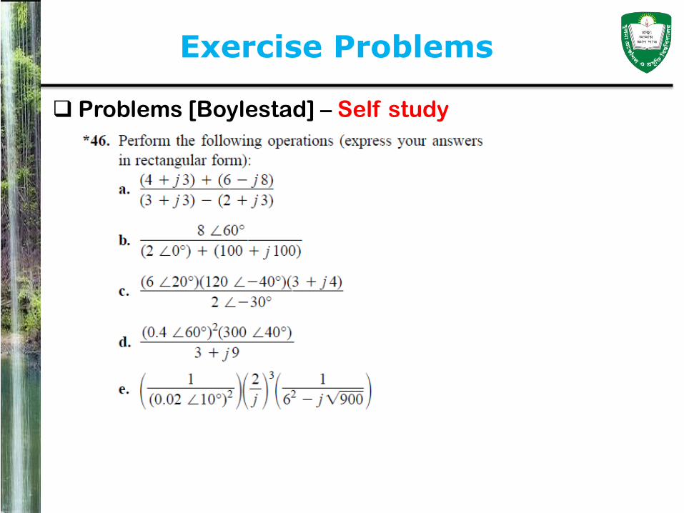
Exercise Problems
Problems [Boylestad] – Self study

সবাইকে ধনযবাদ
স্বাস্থ্য বববধ মেকন চলুন,
বনরাকদ থােুন।