Course 4 Signaling techniques used in classical telephone ...
21
Course 4 Signaling techniques used in classical telephone networks. Zsolt Polgar Communications Department Faculty of Electronics and Telecommunications, Technical University of Cluj-Napoca
Transcript of Course 4 Signaling techniques used in classical telephone ...

Course 4
Signaling techniques used in
classical telephone networks.
Zsolt Polgar
Communications Department
Faculty of Electronics and Telecommunications,
Technical University of Cluj-Napoca

Content of the course
Classification of the signaling techniques;
Access signaling;
“loop start” and “ground start” signaling;
FX (FXS/FXO) signaling;
Trunk signaling;
Basic signaling diagram;
E&M signaling;
MFC-R2 signaling;
Year 2014 – 2015
Semester II Telephony 2

Signaling. General aspects
The signaling in telephony refers to:
Call control signals;
Transmission techniques for control signals;
Call management algorithms;
Purpose of the signaling:
Control of the set up, deployment and interruption of a telephone
connection;
There are several possible classifications:
According to the type of the controlled channel:
subscriber signaling;
used between the subscriber terminal and the local exchange.
trunk signaling;
used on the trunk lines between the exchanges of the public networks, between
PBX and local exchanges and between PBX exchanges.
Year 2014 – 2015
Semester II Telephony 3
Signaling. General aspects
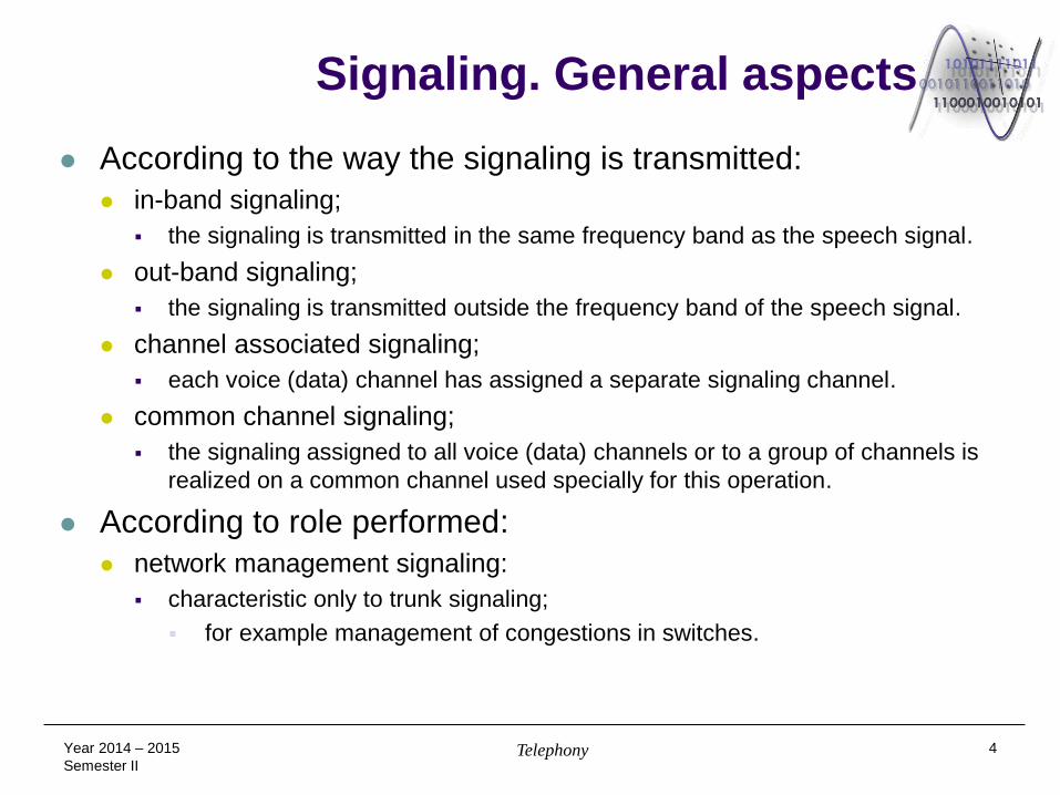
According to the way the signaling is transmitted:
in-band signaling;
the signaling is transmitted in the same frequency band as the speech signal.
out-band signaling;
the signaling is transmitted outside the frequency band of the speech signal.
channel associated signaling;
each voice (data) channel has assigned a separate signaling channel.
common channel signaling;
the signaling assigned to all voice (data) channels or to a group of channels is
realized on a common channel used specially for this operation.
According to role performed:
network management signaling:
characteristic only to trunk signaling;
for example management of congestions in switches.
Year 2014 – 2015
Semester II Telephony 4

Signaling. General aspects alerting signaling;
refers usually to sending to the called terminal (telephone or trunk equipment) of a
ringing signal;
this signal is applied to a line or a trunk.
address signaling;
refers to the transmission of the information related to the called number on
subscriber lines or on trunks;
performed by the terminal or by a switching equipment;
can be accomplished by sending impulses or DTMF tones or special data packets
in digital networks (ISDN);
this information have to be sent in a public network across several links up to the
final completion of the connection;
the address signaling on trunks is realized usually (in classical telephone networks)
by using a MF (Multi-Frequency) type technique:
different to the DTMF technique used on the subscriber line (code 2 of 6);
this signaling has the format: KP + number +ST;
KP (Key Pulse) represents the beginning of the telephone number transmission;
ST (Start) represents the end of this transmission and the beginning of the call
processing – see the following table.
Year 2014 – 2015
Semester II Telephony 5

Signaling. General aspects
MF coding of the characters (digits) used in trunk address signaling:
the frequencies are expressed in Hz;
Year 2014 – 2015
Semester II Telephony 6
Digit/symbol Frequency 1 Frequency 2
KP 1100 1700
KP2 1300 1700
1 700 900
2 700 1100
3 900 1100
4 700 1300
5 900 1300
6 1100 1300
7 700 1500
8 900 1500
9 1100 1500
0 1300 1500
ST 1500 1700

Signaling. General aspects
call supervision (supervisory) signaling;
detects the state or changes the condition of a line or trunk;
there are two possible supervised conditions: ON-HOOK (idle state) and OFF-
HOOK (active state);
when a line/trunk goes OFF-HOOK, it is interpreted as a seizure by the system
and the operating state of the considered line goes from idle to active;
brief changes in the on-hook/off-hook status of a line or a trunk (transition called
wink or hook flash) are also part of the supervision signaling.
out-band signaling is used usually;
an important part of supervisory signaling is represented by the (subscriber)
access signaling and station loop signaling of the exchange.
the access signaling refers to detection of the off-hook state of the calling
(subscriber) terminal or equipment (ex. PBX);
the station loop signaling refers to the answer of the local exchange (or
PBX), signaling related the acceptance or non-acceptance of the access in
the network;
access accepted/granted: the dial tone is transmitted;
unaccepted/rejected access: the busy ton is transmitted.
Year 2014 – 2015
Semester II Telephony 7

Signaling. General aspects
another important component of the supervisory signaling is the answer and
disconnect supervision;
it is important for billing.
call progress indicator signals are tightly related to supervisory signaling;
these signals refer to audible tones that indicate to the calling side the progress
of the telephone call;
these tones are characterized by frequency (or groups of frequencies) and
timing (cadence);
these tones are the following:
dial tone – the CO/PBX is ready to accept the digits of the number from the
subscriber;
busy tone – the called terminal is busy;
reorder tone – the same as the busy tone, but the call is rejected due to
congestion of local/transit exchanges or to unavailability of trunk circuits;
special information tones – faulty line or non existent number, a.s.o.;
ring-back tone – indicates to the calling terminal the establishment of the
connection and the alerting of the called terminal.
Year 2014 – 2015
Semester II Telephony 8

Access signaling The access signaling;
Determines (announces) when a line is off-hook or on-hook;
there are two basic variants of this signaling, namely:
„loop start” type signaling;
„ground start” type signaling.
„loop start” signaling is characteristic to PSTN networks (“Public Switched
Telephone Network”);
when the phone is active a current loop is closed, loop composed of the phone,
wires and the battery located in the exchange;
the current is detected by a current sensing circuit and the exchange responds with
the dial tone;
the incoming call to the phone is signaled by a ringing signal repeated according to
a given on/off pattern;
problems related to this type of signaling:
automatic answer machines could be blocked in off-hook state;
the exchange is not capable to interrupt the connection;
the line/trunk can be seized in the same time from both directions;
the dialing starts in the moment when a call is received;
Year 2014 – 2015
Semester II Telephony 9

Access signaling
the „ground start” type signaling is used especially on the analogue trunk
connections (PBX - CO);
when an equipment tries to access the network (to initiate a call) it connects the
RING lead to the ground;
the exchange (accessed) detects the current through this lead and if it can accept
the call connects the TIP lead to the ground;
the call initiating equipment senses the current through the TIP lead and starts the
call;
the interruption of the connection can be realized by both parts involved in
communication;
a dial tone can be provided to the calling part, but it is optional.
Year 2014 – 2015
Semester II Telephony 10

Access signaling
„loop start” and „ground start” type access signaling;
Year 2014 – 2015
Semester II Telephony 11
Ringing signal
generator
Battery
Current
detector
Ringing signal
generator
Battery
Current
detector
Terminal
Terminal
Ring
Ring
Tip
Tip
PBX (Initiates the call)
Current
detector
Current
detector
Ring
Tip
Trunk module Subscriber module

Access signaling Foreign eXchange (FX) signaling;
called also FXS/FXO signaling – Foreign eXchange Station (FXS) / Foreign
eXchange Office (FXO);
it was developed for connecting PBX exchanges to local exchanges (Central
Office);
an FXS type interface is also used for connecting a multiplexer to the CO;
the interface between the phone device and the CO is similar with the FX
interface;
the FXS interface located in the CO ensures:
the supply voltage;
ringing signal generation;
off-hook detection;
call progress indicator signals.
the FXO interface located in PBX (or phone) ensures:
detection of dial tone;
ringing signal detection;
call progress signal detection.
Year 2014 – 2015
Semester II Telephony 12

Access signaling The principle of FXS/FXO signaling;
Connecting a phone to CO;
Connecting a PCM equipment to CO.
Year 2014 – 2015
Semester II Telephony 13
Central
Office (CO)
switch
Call receiving terminal;
Loop Start
signaling
Call originating terminal;
Loop Start
signaling
Phone goes Off Hook
CO sends ringing signal
CO sends dial tone
Phone goes Off Hook
Central Office
(CO) switch
MU
X P
CM
MU
X P
CM
FXS FXO FXS “FXO”
”
T1/E1
circuit Call receiving
terminal;
Loop Start
signaling
Call originating
terminal;
Loop Start
signaling
FXO goes Off Hook
CO calls FXO
FXO goes Off Hook
CO sends dial tone
FXS calls the terminal
The terminal goes Off Hook
The terminal goes Off Hook
FXS sends dial tone
originating
receiving

Access signaling
Allocation of AB bits to signals associated to FXS/FXO
signaling:
GS: Ground Start;
Year 2014 – 2015
Semester II Telephony 14
Signal / direction Forward (to FXO) Backward (to FXS)
IDLE / ON HOOK AB = 0 1 AB = 0 1
OFF HOOK AB = 1 1
RINGING AB = 0 0
RING GROUND AB = 0 0 (only GS)
TIP CLOSED AB = 0 1 (only GS)
FORWARD DISCONNECT AB = 1 1 (only GS)

Trunk signaling
Signaling sequence associated to a telephone call in a
classical telephone network involving a trunk connection;
Year 2014 – 2015
Semester II Telephony 15
Central
office
Central
office
Subscriber
loop Subscriber
loop Truk
On-hook On-hook On-hook
Off-hook
Dial tone
Number Off-hook (seize)
Off-hook
On-hook Wink
Number
Ringing signal Ring back signal
Off-hook Off-hook Billing starts
On-hook
Ring back signal terminated Ringing terminated
Connected call ; voice path
On-hook Disconnect Billing ends

Trunk signaling
E&M (“Ear and Mouth” sau “recEive and transMit”) signaling;
signaling technique developed for trunk signaling between PBX and PSTN
exchanges;
there were developed different signaling variants (types I - V);
this signaling technique is based on two signals, called M and E;
the M signal is generated by the trunk call initiating exchange;
the E signal is a response sent by the exchange located at the opposite end of the
trunk;
the E&M signaling channel is separated from the voice channel of the trunk;
using these two signals are coded the states of the equipments located at the two
ends of the trunk connection:
equipments which can be in the IDLE / ON HOOK state or in the BUSY (SEIZED)
/ OFF HOOK state;
using some impulses (activation – deactivation : „wink”) other information can be
transmitted on these lines as well.
Year 2011 – 2014
Semester II
Telephony 16

Trunk signaling
E&M signaling basic schematics;
Sending of the called number on the trunk connection is realized
using a MF type (coding) transmission on the voice path;
it is ensured a larger speed of the address signaling;
Year 2014 – 2015
Semester II Telephony 17
PBX-A
PBX-B
Signaling
Signaling
Communication voice path
48V 48V E E
M M
Request Request
Listen Listen
Signaling path

Trunk signaling
Types of E&M signaling:
E&M immediate:
the trunk call initiating equipment goes OFF HOOK and transmits immediately the
called number;
after the reception of the number the trunk equipment on the opposite end goes
OFF-HOOK during the entire duration of the call;
both equipments can terminate the call by going in the ON-HOOK state;
there is the possibility that the called trunk equipment is not ready to receive the
number;
E&M wink: the terminal equipment responds to an OFF-HOOK state of the calling equipment
with a short OFF-HOOK impulse („wink”) in the moment when is ready to receive the
called number;
the opening of the voice path and the starting of the billing process is achieved after
the E signal goes OFF-HOOK.
Year 2014 – 2015
Semester II Telephony 18

Trunk signaling
Signaling sequence corresponding to E&M wink:
E&M wink-wink:
the terminal equipment responds to an OFF-HOOK state of the calling equipment
with a short impulse on signal E;
the call originating equipment sends the number in MF code on the voice path;
the receiving equipment sends another short impulse on signal E, signaling that it
received all the digits.
Year 2014 – 2015
Semester II Telephony 19
Seized / Off Hook
Seized / Off Hook
Calling
equipment
Called
equipment
Idle / On Hook
Idle / On Hook Answer
Call disconnect
Call disconnect
Address signaling
using DTMF tones
Signal M
Signal E
200 ms
Incoming call

Trunk signaling
Allocation of AB(CD) bits to physical signals characteristic to
E&M signaling:
MFC-R2 signaling – „Multifrequency Compelled R2 Signaling
System”, called also R2 signaling;
the R2 term refers to the region 2, considered to be Europe (USA was
considered region 1);
it is called also inter-register signaling;
register – signaling equipment used to control the switching process – is the part
dedicated to address signaling, switching control and (partially) control of the
connection – for ex. billing control);
Year 2014 – 2015
Semester II Telephony 20
Direction State A B C D
Transmission Idle/On-Hook 0 0 0 0
Transmission Seized/Off-Hook 1 1 1 1
Reception Idle/On-Hook 0 0 0 0
Reception Seized/Off-Hook 1 1 1 1
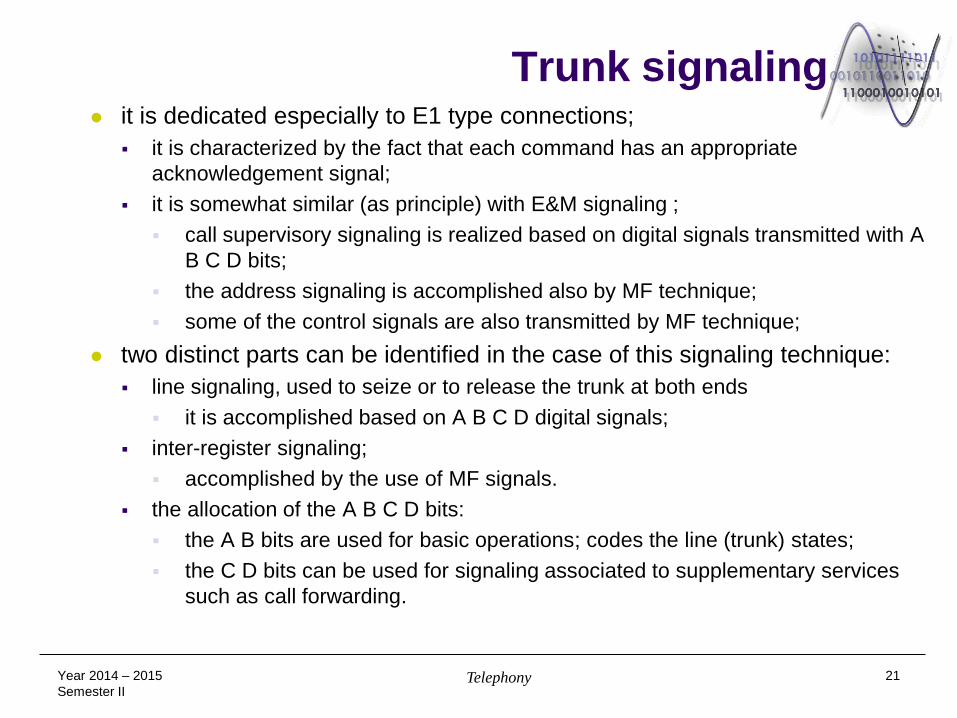
Trunk signaling it is dedicated especially to E1 type connections;
it is characterized by the fact that each command has an appropriate
acknowledgement signal;
it is somewhat similar (as principle) with E&M signaling ;
call supervisory signaling is realized based on digital signals transmitted with A
B C D bits;
the address signaling is accomplished also by MF technique;
some of the control signals are also transmitted by MF technique;
two distinct parts can be identified in the case of this signaling technique:
line signaling, used to seize or to release the trunk at both ends
it is accomplished based on A B C D digital signals;
inter-register signaling;
accomplished by the use of MF signals.
the allocation of the A B C D bits:
the A B bits are used for basic operations; codes the line (trunk) states;
the C D bits can be used for signaling associated to supplementary services
such as call forwarding.
Year 2014 – 2015
Semester II Telephony 21