Coupling efficiency effects of launching a fringe pattern into a single-mode optical fiber
6
Coupling efficiency effects of launching a fringe pattern into a single-mode optical fiber M. Kamel Amara and Noureddine Melikechi Applied Optics Center of Delaware and Department of Physics, Delaware State University, Dover, Delaware 19901 Received December 18, 2002; revised manuscript received May 22, 2003 We discuss the effects on coupling efficiency of launching an optical fringe pattern into a single-mode optical fiber. We show that under some circumstances, coupling efficiencies of ;90% can be obtained by the launch- ing of the central fringe of a two-beam interference pattern into the fiber. Theoretical calculations based on mode overlapping integrals show that, compared with commonly used coupling schemes, it is possible to im- prove greatly the coupling efficiency into an optical fiber. By using a He-Ne laser operating at 633 nm and an optical fiber with a mode field diameter of 3.3 mm and N.A. of 0.16, we have obtained a coupling efficiency of ;91% at an interfering half-angle of ;60 mrad, in good agreement with our theoretical predictions. © 2003 Optical Society of America OCIS codes: 060.0060, 060.1810, 060.2340, 060.2430, 120.3180, 220.2560. 1. INTRODUCTION In the growing field of optical telecommunications, there is a need for a high level of integration and performance of various optical components. This need is driven in part by recent developments of highly efficient optical components such as light sources, wavelength-dense mul- tiplexers, photodetectors, optical couplers, and switches. 1–3 To respond adequately to this need, several problems need to be addressed. These include signal dis- persion, presence of undesired nonlinear effects, signal absorption in glass, and relatively low coupling efficiency, defined as the ratio of the optical power transmitted through a fiber to that of the power incident upon it. 4,5 The relatively low coupling efficiency typically associated with optical fibers remains a key issue that needs to be addressed. To couple light into an optical element such as a single- mode fiber (SMF) or waveguide, it is customary to use a focusing lens with a small f-number. 1,6 This configura- tion yields a diffraction-limited spot size of the focused beam. For an ideal focused Gaussian beam, and by using an aberration-free lens, the minimum spot size can be written as 7,8 D out 5 4 l f # p , (1) where l is the laser wavelength and f # represents the ra- tio of the focal length of the lens to the diameter of the illuminated surface of the lens. In practice, the mini- mum spot size that can be achieved is even larger because an ideal focused Gaussian spot is difficult to obtain as a result of aberrations that the lens may introduce. In the case of SMFs, which typically have core sizes of 3 – 9 mm, this limits the coupling efficiency of non-Gaussian ( M 2 . 1) beams into the fiber to ;50%. Moreover, the smaller the fiber core size, the lower the coupling effi- ciency. As a result, the use of a focusing lens to couple light into an optical fiber is adequate only for large-core multimode fibers and the method becomes increasingly complex and lossy for SMFs. 9 Other alternatives, such as butt coupling and prism coupling techniques, have been proposed but yield limited success. The former technique has been shown to be moderately efficient but suffers considerably from fiber-core-cladding eccentricity and can be utilized only in permanent junctions. 10 The latter approach is suitable only for large fiber-bending- angle configurations and requires stripping of the fiber protections and cladding. 11 In an earlier publication, we demonstrated experimen- tally that by using an interference scheme in nonlinear optical waveguides, we can enhance the generation of second-harmonic optical radiation. 12 Recently, we have shown that it is possible to obtain an optical coupling ef- ficiency of 91% rms with nearly Gaussian beams ( M 2 5 1.1) into a single-mode fiber with a 3.3-mm mode field diameter and a N.A. of 0.16. 13 In this paper, we extend our previous work and provide a discussion of the effects on coupling of light into single-mode fibers of the sizes of the interference fringes generated from two nearly Gauss- ian beams. We compare the behavior of the single-beam technique to the interference coupling method when these setups are subjected to various misalignments. 2. THEORETICAL CONSIDERATIONS The spatial width d of the central fringe of two interfering plane-wave beams (in air) is inversely proportional to the half-angle u of the two interfering beams since d 5 l /2 sin u, where l is the laser wavelength. 7 Figure 1 shows the measured and calculated widths of a fringe. Experimentally, the fringes were generated from two nearly Gaussian ( M 2 nearly equal to 1.6) interfering beams operating at 633 nm and their widths were mea- sured using a CCD camera (Cohu from SensorPhysics™). The calculated fringes were obtained by assuming two in- terfering plane waves and two interfering Gaussian beams. The width of the fringes is estimated by calculat- M. Amara and N. Melikechi Vol. 20, No. 10/October 2003/J. Opt. Soc. Am. B 2031 0740-3224/2003/102031-06$15.00 © 2003 Optical Society of America
-
Upload
noureddine -
Category
Documents
-
view
216 -
download
3
Transcript of Coupling efficiency effects of launching a fringe pattern into a single-mode optical fiber

M. Amara and N. Melikechi Vol. 20, No. 10 /October 2003 /J. Opt. Soc. Am. B 2031
Coupling efficiency effects of launching a fringepattern into a single-mode optical fiber
M. Kamel Amara and Noureddine Melikechi
Applied Optics Center of Delaware and Department of Physics, Delaware State University, Dover, Delaware 19901
Received December 18, 2002; revised manuscript received May 22, 2003
We discuss the effects on coupling efficiency of launching an optical fringe pattern into a single-mode opticalfiber. We show that under some circumstances, coupling efficiencies of ;90% can be obtained by the launch-ing of the central fringe of a two-beam interference pattern into the fiber. Theoretical calculations based onmode overlapping integrals show that, compared with commonly used coupling schemes, it is possible to im-prove greatly the coupling efficiency into an optical fiber. By using a He-Ne laser operating at 633 nm and anoptical fiber with a mode field diameter of 3.3 mm and N.A. of 0.16, we have obtained a coupling efficiency of;91% at an interfering half-angle of ;60 mrad, in good agreement with our theoretical predictions. © 2003Optical Society of America
OCIS codes: 060.0060, 060.1810, 060.2340, 060.2430, 120.3180, 220.2560.
1. INTRODUCTIONIn the growing field of optical telecommunications, thereis a need for a high level of integration and performanceof various optical components. This need is driven inpart by recent developments of highly efficient opticalcomponents such as light sources, wavelength-dense mul-tiplexers, photodetectors, optical couplers, andswitches.1–3 To respond adequately to this need, severalproblems need to be addressed. These include signal dis-persion, presence of undesired nonlinear effects, signalabsorption in glass, and relatively low coupling efficiency,defined as the ratio of the optical power transmittedthrough a fiber to that of the power incident upon it.4,5
The relatively low coupling efficiency typically associatedwith optical fibers remains a key issue that needs to beaddressed.
To couple light into an optical element such as a single-mode fiber (SMF) or waveguide, it is customary to use afocusing lens with a small f-number.1,6 This configura-tion yields a diffraction-limited spot size of the focusedbeam. For an ideal focused Gaussian beam, and by usingan aberration-free lens, the minimum spot size can bewritten as7,8
Dout 5 4lf#
p, (1)
where l is the laser wavelength and f# represents the ra-tio of the focal length of the lens to the diameter of theilluminated surface of the lens. In practice, the mini-mum spot size that can be achieved is even larger becausean ideal focused Gaussian spot is difficult to obtain as aresult of aberrations that the lens may introduce. In thecase of SMFs, which typically have core sizes of 3–9 mm,this limits the coupling efficiency of non-Gaussian (M2
. 1) beams into the fiber to ;50%. Moreover, thesmaller the fiber core size, the lower the coupling effi-ciency. As a result, the use of a focusing lens to couplelight into an optical fiber is adequate only for large-core
0740-3224/2003/102031-06$15.00 ©
multimode fibers and the method becomes increasinglycomplex and lossy for SMFs.9 Other alternatives, suchas butt coupling and prism coupling techniques, havebeen proposed but yield limited success. The formertechnique has been shown to be moderately efficient butsuffers considerably from fiber-core-cladding eccentricityand can be utilized only in permanent junctions.10 Thelatter approach is suitable only for large fiber-bending-angle configurations and requires stripping of the fiberprotections and cladding.11
In an earlier publication, we demonstrated experimen-tally that by using an interference scheme in nonlinearoptical waveguides, we can enhance the generation ofsecond-harmonic optical radiation.12 Recently, we haveshown that it is possible to obtain an optical coupling ef-ficiency of 91% rms with nearly Gaussian beams (M2
5 1.1) into a single-mode fiber with a 3.3-mm mode fielddiameter and a N.A. of 0.16.13 In this paper, we extendour previous work and provide a discussion of the effectson coupling of light into single-mode fibers of the sizes ofthe interference fringes generated from two nearly Gauss-ian beams. We compare the behavior of the single-beamtechnique to the interference coupling method when thesesetups are subjected to various misalignments.
2. THEORETICAL CONSIDERATIONSThe spatial width d of the central fringe of two interferingplane-wave beams (in air) is inversely proportional to thehalf-angle u of the two interfering beams since d5 l/2 sin u, where l is the laser wavelength.7 Figure 1shows the measured and calculated widths of a fringe.Experimentally, the fringes were generated from twonearly Gaussian (M2 nearly equal to 1.6) interferingbeams operating at 633 nm and their widths were mea-sured using a CCD camera (Cohu from SensorPhysics™).The calculated fringes were obtained by assuming two in-terfering plane waves and two interfering Gaussianbeams. The width of the fringes is estimated by calculat-
2003 Optical Society of America

2032 J. Opt. Soc. Am. B/Vol. 20, No. 10 /October 2003 M. Amara and N. Melikechi
ing the distance between the two first-order dark fringesin the interference pattern. In this case, the quality ofthe beams used (M2 5 1.6) has a minor effect on thefringe size (variation ,0.5%) because the intensity distri-bution of the beams is nearly Gaussian.
A. Comparison of the Spot Sizes of Beams Obtained byUsing Interference with Those Obtained by UsingDiffraction-Limited FocusingFigure 1 shows that the interference technique allows thegeneration of minimal spot sizes equal to ;1/2 l at inter-fering half-angles close to 90°. To obtain a similar sizefor a single diffraction-limited beam requires the use of alens with f# ' 0.39 (N.A. ' 1.27). Such a lens is notreadily available because it is difficult to produce goodquality, aberration-free, small-f# lenses. However, by us-ing appropriate interfering angles, it is possible to obtaindiffraction-limited beam spot sizes relatively easily.
Since the spatial profile of a single-mode fiber outputbeam is substantially Gaussian (error , 1%), coupling abeam with an identical Gaussian profile yields an idealcoupling efficiency of 100%. This is referred to as modematching. Commercially available, high-quality, high-N.A. lenses can be used for such tasks. However, theselenses are bulky and their use between each coupling offibers and–or optical component is not practical.14 Incontrast, the interference approach generates a smallerspot size and, as a result, relaxes the limit of acceptanceof the optical fiber and reduces sensitivity to the axial po-sitioning of the fiber.
B. Coupling Efficiency CalculationsTo compare the expected efficiencies of coupling intoSMFs obtained by using the single-beam and the interfer-ence schemes, we perform numerical calculations basedon the overlapping integrals of the fiber mode field andthe intensity distribution of the input light.15 This ap-proach takes into account light coupling and propagationin the fiber cladding. Marcusse has shown that a Gauss-ian radial distribution fits (error , 1%) the step-index fi-ber mode field.16 The diameter 2wD of the SMF Gauss-ian mode field profile can be determined empirically byusing the Marcusse equation relating the radius of themode field to the core size a and the normalized fiber
Fig. 1. Theoretical curves corresponding to two interferingplane-wave beams or two interfering Gaussian beams (solidcurve) fit substantially the measured fringe width data (tri-angles). A He-Ne laser wavelength of 633 nm is used. The ex-perimental error bars are within the presented points
number V.16 The coupling efficiency h can be obtainedby calculating the normalized integral:
h 5
E0
av0
exp~2r2/vD2 !f~r !rdr
S E0
av0
exp~22r2/vD2 !rdrE
0
av0
f 2~r !rdr D 1/2 , (2)
where f(r) is the incident light intensity profile functionand exp(2r2/wD
2 ) is the fiber mode distribution. We esti-mate the coupling efficiencies for the single-focused beamand the interference fringe by using the correspondingprofile functions f(r) coupled into the same SMF. TheGaussian beam profile function is determined by(1/w0)exp(2r2/w0
2), where w0 is the focused beam waist.uE1(r) 1 E2(r)u2 represents the interference intensityprofile function, where Ei(r) stands for the amplitude ofthe two interfering Gaussian beams (i 5 1, 2). The ex-pression for the total power is given in Ref. 17.
To compare the single-beam and the interferenceschemes, the same beam waist w0 at the fiber is consid-ered for the intensity profiles of the interfering beams.The integration boundary constant a has been set suffi-ciently large to take into account light propagation withinthe cladding. For convenience, we define a relative cou-pling factor G:
G 5h int
hsb, (3)
where h int and hsb represent the interference and thesingle-beam efficiencies, respectively. As detailed in Ref.13 the redistribution of optical power along one trans-verse axis due to interference increases the amount ofpower launched into the fiber, which can enhance the cou-pling efficiency. As the angle between the interferingbeams increases, the width of the central fringe decreasesand the secondary dark fringes around the central fringeare coupled into the fiber. As a result the relative cou-pling factor decreases since the mode mismatch betweenthe interference pattern and the fiber mode gradually in-creases.
We calculate the coupling efficiency for a single He-Nebeam with a 1/e2-beam size of 6 mm coupled into a single-mode fiber with a N.A. of 0.16 and a mode field diameterof 3.3 mm. By use of Eq. (2) and for an integration bound-ary constant a of 20, which corresponds to a penetrationdepth into the cladding larger than the core radius bymore than an order of magnitude, we find this couplingefficiency to be 85%. For the same experimental condi-tions, the interference scheme can yield higher couplingefficiencies. In Ref. 13 we show that this enhancementtakes place for interfering half-angles smaller than 90mrad. The relative coupling factor is maximum for theangle at which the mode field and the interference profilesare best matched. This occurs for a half-angle of 53mrad, yielding an efficiency of ;91%. For half-angleslarger than 90 mrad, the single-beam coupling is more ef-ficient because there is a gradual deterioration of themode matching between the interference profile and thefiber mode field distribution.

M. Amara and N. Melikechi Vol. 20, No. 10 /October 2003 /J. Opt. Soc. Am. B 2033
Figure 2 illustrates the case of three different opticalcoupling situations but with the same characteristic pa-rameter V w0 of 76.32. Although different optical fiberswith different normalized fiber numbers and differentwavelengths and beam characteristics are used, the rela-tive coupling factor remains essentially unchanged. Thisshows that the relative coupling factor is quasi-invariantwith the characteristic parameter. The coupling charac-teristics are quasi-identical in the Marcusse approxima-tion (variations , 1%), especially in the region where in-terference is the most efficient coupling scheme. As aresult, we suggest that the characteristic parameter beconsidered a key one when investigating coupling of lightinto optical fibers.
To understand further the effects of two-beam interfer-ence on coupling efficiency, we show in Fig. 3 the behaviorof the relative optical coupling factor as a function of theinterference half-angle for various characteristic param-eters. The relative coupling factor increases with in-creasing values of the normalized fiber number and/or thefocused beam waist. However, for angles larger than 80mrad, single-beam coupling is more efficient since thecoupling factor decreases monotonically from unity for in-creasing interference half-angles. For a given interferinghalf-angle and a growing value of the characteristic pa-rameter, we note that the relative coupling factor in-creases as a result of the decrease in single-beam couplingefficiency. Furthermore, Fig. 3 shows that for differentcharacteristic parameters, the maximum relative factor isobtained for different interfering angles: For a givenvalue of the normalized fiber number, increasing thewaist of the focused beam yields a decrease in the powerintensity of the coupled fringe so that the total power inthe beams is conserved. The maximum efficiency is thusobtained for larger central fringe widths, i.e., small inter-fering angles, to compensate for the loss in total powerlaunched from the same fringe. The same conclusionscan be drawn for a given focused beam waist and varyingnormalized fiber number.
Fig. 2. Invariance of the coupling properties with the character-istic parameter Vwo 5 76.32. The same Corning SMF-28 fiber(a 5 4.1 mm and N.A. 5 0.14) is considered. The wavelengthsand the beam radii are, respectively: a, 1310 nm and 27.72 mm;b, 1550 nm and 32.8 mm; c, 1803 nm and 38.16 mm.
Figure 4 shows the variations of the efficiency of thesingle-beam coupling and the relative coupling factor as afunction of the beam radius. As expected, the single-beam coupling efficiency reaches a maximum value whenthe waist of the focused beam equals the core size of theoptical fiber and decreases in all other cases. Since inmost practical cases, the beam radii are larger than themode field radius of SMFs, we focus our analysis on theinterval where the beam radius is larger than the moderadius. Our calculations show that the interference cou-pling efficiency also decreases with increasing mode mis-match. However, the rate of decrease is slower than inthe single-beam coupling scheme, which explains the in-crease in the relative coupling factor for increasing waistsizes of the beam and for interfering angles smaller than
Fig. 3. Relative coupling factor variations as a function of theinterference half-angle for different characteristic parameter val-ues.
Fig. 4. Variations of the relative coupling factor and the single-beam coupling efficiency as a function of the beam radius for dif-ferent interference half-angle values (in radians). The solidcurve joins the calculated single-beam coupling efficiency. Thenormalized fiber number considered in these calculations isV 5 2.32 for a Corning SMF-28 fiber. The characteristic param-eter ranges from 0 to V15a, or 57.42.

2034 J. Opt. Soc. Am. B/Vol. 20, No. 10 /October 2003 M. Amara and N. Melikechi
80 mrad. Furthermore, Fig. 4 shows that the relativecoupling factor reaches a plateau for decreasing beamwaist values when the interference half-angle increases.This decrease is necessary to compensate for the loss ofpower in the coupled interference fringe. In the plateauthe single beam and the interference coupling efficienciesbehave identically because the power of the coupled lightin both cases decays at about the same rate with increas-ing beam radii.
3. EXPERIMENTAL RESULTS ANDDISCUSSIONTo test the theoretical results obtained, we used a Mich-elson interferometer to generate the two interferingbeams. This is shown in Fig. 5. This scheme permits usto control the difference in path length of the two beamsand to monitor the phase difference. The antireflection-coated lens L serves to focus the beams to obtain the samespatial beam profiles and generate an interference pat-tern at the focal plane of the lens. The focal length f ofthe lens is 14.5 mm with a clear aperture diameter of 8mm. We use a vertically polarized He-Ne laser operatingat 633 nm and delivering a nearly Gaussian beam withM2 ' 1.2. The coupling is tested with a 2-m-long com-mercial step-index SMF (3M, model FS-SC-3314). Thediameters of the fiber mode field and cladding are 3.3 mmand 80 mm, respectively. The optical fiber has a N.A. of0.16 and thus presents an acceptance angle of ;9°. Thisfiber is characterized by a normalized fiber number V5 5 2.62 6 0.66, in agreement with the 2.4048 valuecommonly associated with SMFs.1,2 Since the waist of afocused beam is inversely proportional to the input beamdiameter at the focusing lens, an auxiliary lens is used toexpand the 1-mm-wide (1/e2) incident beam before thebeam splitter by a factor of 3. The 1/e2 size of each beamat the fiber input plane is measured by a 403 microscopeobjective and a CCD camera to be 6 6 1 mm, resulting ina V w0 parameter of 8 6 1.4 mm. Inspection of Fig. 3shows that for this value, the single-beam scheme is ex-pected to be equally efficient as, or more efficient than,the interference scheme. However, the experimental re-sults obtained with the interference coupling scheme aresignificantly better than predicted by our calculations.This discrepancy is due to the fact that in our calcula-tions, the light beams were assumed to be perfectlyGaussian.
Fig. 5. Michelson interferometer setup used to compare the twocoupling techniques. M, mirror; L, lens; BS, beam splitter; FO,fiber optic.
Figure 6 shows the experimental results obtained.The output power from the fiber is plotted as a function oftime for the two schemes. The data at (a) show thepower of the light transmitted from the fiber when thecentral fringe is launched, while the data at (b) show thetransmitted power when only a single beam is launchedinto the fiber. The latter results were obtained by block-ing successively one of the two interfering beams. Thehighest coupling efficiencies are obtained for interferinghalf-angles of about 60 6 10 mrad. The interferencescheme yields a coupling efficiency of 91 6 6%, about 1.7times larger than the coupling efficiency obtained withthe single-beam approach. The values of theinterference-coupling efficiencies are obtained by dividingthe measured output power from the fiber by the sum ofthe measured powers of the two input beams (to the fi-ber). The slight difference between the signals of the twooutput beams shown in Fig. 6(b) is due to a difference ininput powers. This reduces the fringe contrast and therelative coupling factor by less than 8%.
The high coupling efficiency obtained in the two-beaminterference case can be explained by two main factors.First, at half-angles smaller than 90 mrad the interfer-ence pattern at the input facet of the fiber is a unique cen-tral fringe confining about 97% of the optical powerwithin a fringe of half-width of 1.1 wD . Second, at half-angles less than 90 mrad, the mode matching between theprofile of the fiber and that of the field obtained using in-terfering beams is better than that with a non-Gaussiansingle beam. At the interfering half-angle of 606 10 mrad, the 1/e2 fringe size equals 3.5 6 0.5 mm,which fits the fiber mode field diameter of 3.3 mm muchbetter than the diameter—6 mm—of the single beam.The single-beam approach yields a coupling efficiency of54 6 4%. This relatively low efficiency is due to the non-Gaussian profile of the focused laser beam used and theresulting poor matching with the fiber mode. The tightfocusing (the ratio of the beam size at the lens to the beamwaist at the focus is ;500) introduces significant aberra-tions that alter the quality of the Gaussian beam, increas-ing its M2 value.
For small interfering angles, the enhancement in thecoupling efficiency due to the use of the interference ap-
Fig. 6. Comparison, at a wavelength of 633 nm and a charac-teristic parameter Vwo 5 8 6 1.4 mm, of the output powers froma single-mode optical fiber shows a relative coupling factor of 1.7between (a) the two-beam interference coupling and (b) the twosingle focused beams in a Michelson experiment.
M. Amara and N. Melikechi Vol. 20, No. 10 /October 2003 /J. Opt. Soc. Am. B 2035
proach occurs mainly in the direction of the spatial con-finement of the optical power. Along the direction per-pendicular to this direction of propagation, noenhancement in coupling efficiency is possible since thebeam remains spatially unmodified. Therefore, it ispractical to set the interference axis along the directionpresenting the more aberrations.
To show clearly the effects of spatial misalignments onthe coupling efficiency, we used a slightly modified versionof the above setup and performed measurements of cou-pling efficiencies with interfering angles larger than theacceptance angle of the fiber using the same lens L.18,19
The experimental setup is shown in Fig. 7; used com-monly in laser Doppler velocimetry techniques, it offersfine adjustments of the interference angle. Neglectingthe additional off-axis aberrations introduced to the fo-cused beam, this technique allows adjusting the interfer-ence angle by sliding the prism and the beam splitter inopposite directions. In the single-beam scheme, thebeam splitter is removed and the prism is translatedtransversely towards the optical axis of the lens so thatthe single beam is focused in the same manner as the in-terfering beams. For an interfering half-angle of 10°,which exceeds the value set by the fiber N.A., part of the
Fig. 7. Adjustable-angle, two-beam interference set-up. BS,beam splitter; P, Prism. The solid-line beams interfere with alarger half-angle than the dashed-line beams obtained by slidingBS and P in opposite directions equally.
optical power is not guided inside the SMF. In this case,the interference coupling scheme yields an efficiency ofabout 30 6 7%, while the single-beam coupling schemeyields a maximum efficiency of about 54 6 4%. The ex-perimental interference coupling efficiency is lower thanthe theoretical value—76%—predicted by Eq. (2). Thisdiscrepancy may be due to a mismatch between the N.A.of the fiber and that of the coupled fringe.6
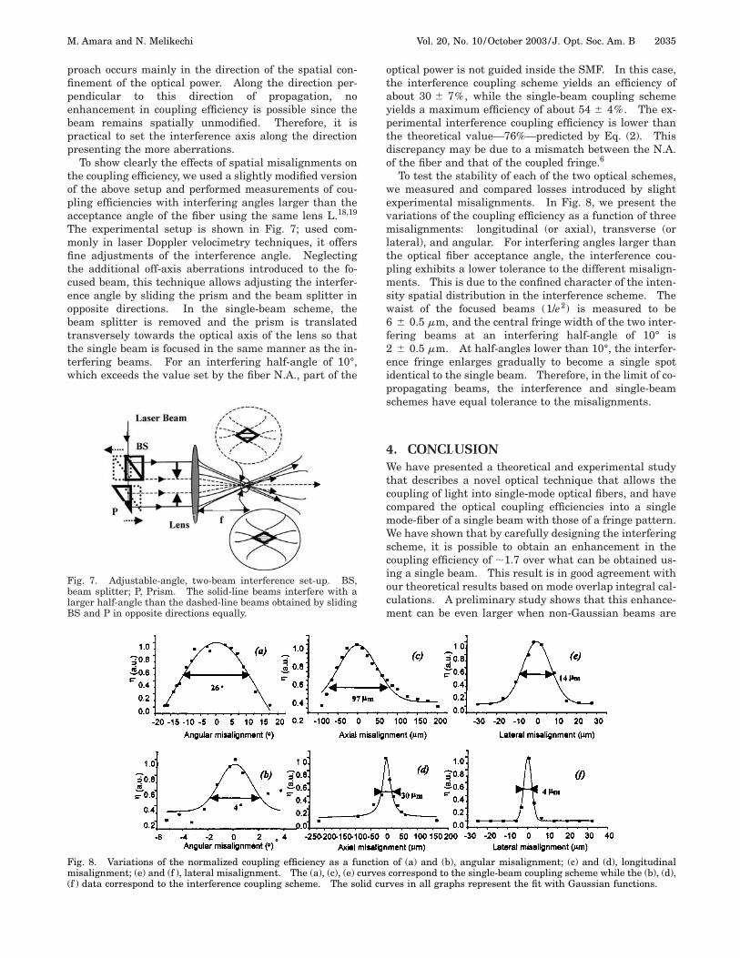
To test the stability of each of the two optical schemes,we measured and compared losses introduced by slightexperimental misalignments. In Fig. 8, we present thevariations of the coupling efficiency as a function of threemisalignments: longitudinal (or axial), transverse (orlateral), and angular. For interfering angles larger thanthe optical fiber acceptance angle, the interference cou-pling exhibits a lower tolerance to the different misalign-ments. This is due to the confined character of the inten-sity spatial distribution in the interference scheme. Thewaist of the focused beams (1/e2) is measured to be6 6 0.5 mm, and the central fringe width of the two inter-fering beams at an interfering half-angle of 10° is2 6 0.5 mm. At half-angles lower than 10°, the interfer-ence fringe enlarges gradually to become a single spotidentical to the single beam. Therefore, in the limit of co-propagating beams, the interference and single-beamschemes have equal tolerance to the misalignments.
4. CONCLUSIONWe have presented a theoretical and experimental studythat describes a novel optical technique that allows thecoupling of light into single-mode optical fibers, and havecompared the optical coupling efficiencies into a singlemode-fiber of a single beam with those of a fringe pattern.We have shown that by carefully designing the interferingscheme, it is possible to obtain an enhancement in thecoupling efficiency of ;1.7 over what can be obtained us-ing a single beam. This result is in good agreement withour theoretical results based on mode overlap integral cal-culations. A preliminary study shows that this enhance-ment can be even larger when non-Gaussian beams are
Fig. 8. Variations of the normalized coupling efficiency as a function of (a) and (b), angular misalignment; (c) and (d), longitudinalmisalignment; (e) and (f ), lateral misalignment. The (a), (c), (e) curves correspond to the single-beam coupling scheme while the (b), (d),(f ) data correspond to the interference coupling scheme. The solid curves in all graphs represent the fit with Gaussian functions.

2036 J. Opt. Soc. Am. B/Vol. 20, No. 10 /October 2003 M. Amara and N. Melikechi
considered. We are currently further developing our the-oretical model by taking into account the N.A. matchingbetween the single beam or the fringe and the optical fi-bers. We believe that this effort will yield better agree-ment between theory and experiment. Furthermore, weshow that to optimize the coupling efficiency of laser lightinto SMFs, the invariant characteristic factor V w0 is animportant descriptive parameter that must be considered.
One serious drawback to the coupling–interferencetechnique is its high sensitivity to mechanical vibrations.To overcome this problem somewhat, we are planning toembed the optical interference components in appropriateMach–Zenhder-like waveguides. This may lead to theuse of these waveguides as active components for digitalmodulation with higher extinction ratios and lower inser-tion losses and driving voltages than the actual modula-tors.
ACKNOWLEDGMENTSWe thank William D. Jemison for valuable discussions,and the Office of Naval Research for financial support un-der award N00014-00-1-0788.
Corresponding author N. Melikechi may be reached bye-mail to [email protected].
REFERENCES1. L. B. Jeunhomme, Single-Mode Fiber Optics: Principles
and Applications (Optical Engineering Series, No. 23) (Mar-cel Dekker, New York, 1983).
2. A. Ghatak and K. Thyagarajan, Introduction to Fiber Optics(Cambridge University, Cambridge, England, 1999).
3. M. Lange, E. Bryant, M. Myers, J. Myers, R. Wu, and C.Hardy, ‘‘High-gain short length phosphate glass erbium-doped fiber amplifier material,’’ Vol. 54 of 2001 OSA OpticalFiber Communications, Trends in Optics and Photonics Se-ries (Optical Society of America, Washington, D.C., 2001).
4. B. Porter, ‘‘Arrayed waveguide gratings,’’ Fiber Optic Prod-uct News, December (2000), pp. 84–85.
5. N. Khan and J. Rue, ‘‘Focus on the 40Gb/s challenge,’’ FiberSystems International 1, 33–36 (2000).
6. G. Keiser, Optical Fiber Communications (McGraw-Hill,New York 1983), Chap. 5.
7. B. A. Saleh and M. C. Teich, Fundamentals of Photonics(Wiley, New York, 1991), Chap. 3.
8. A. E. Siegman, Lasers (University Science, Mill Valley, Ca-lif., 1986), Chap. 2.
9. F. C. Hallard, Fiber Optics Handbook for Engineers and Sci-entists (McGraw-Hill, New York, 1990).
10. V. Vusirikala, S. S. Saini, R. E. Bartolo, R. Whaley, S. Agar-wala, F. G. Johnson, D. R. Stone, and M. Dagenais, ‘‘Highbutt-coupling efficiency to single-mode fibers using a 1.55mm InGaAsP laser integrated with a tapered ridge modetransformer,’’ IEEE Photon. Technol. Lett. 9, 1472–1474(1997).
11. U. Peschel, L. Leine, F. Lederer, and C. Wachter, ‘‘Bendingthe path of light with a microprism,’’ Vol. 56 of 2001 Con-ference on Laser & Electro-Optics, Trends in Optics andPhotonics Series (Optical Society of America, Washington,D.C., 2001).
12. Z. S. Benaich, R. D. Pradhan, S. M. Mian, and N. Melikechi,‘‘Effects of interference in quasi-phase-matched, periodi-cally segmented, potassium titanyl phosphate waveguides,’’Appl. Phys. Lett. 75, 3261–3263 (1999).
13. M. K. Amara and N. Melikechi, ‘‘Enhancement of the cou-pling efficiency in optical fiber using two-beam optical inter-ference,’’ Appl. Phys. Lett. 80, 3494–3496 (2002).
14. S. B. Ippolito, B. B. Goldberg, and M. S. Unlu, ‘‘High-spatial-resolution subsurface microscopy,’’ Appl. Phys. Lett.78, 4071–4073 (2001).
15. A. K. Ghatak and A. Sharma, ‘‘Single mode fiber character-istics,’’ J. Inst. Electron. Telecom. Engrs. (India) 32, 213–219 (1986).
16. D. Marcuse, ‘‘Loss analysis of single mode fiber splices,’’Bell Syst. Tech. J. 56, 703–717 (1977).
17. A. Y. Hamad and J. P. Wicksted, ‘‘Volume grating producedby intersecting Gaussian beams in an absorbing medium:a Bragg diffraction model,’’ Opt. Commun. 138, 354–356(1997).
18. C. Ozkul, N. Anthore, M. K. Amara, S. Leroux, and S. Ras-set, ‘‘Optical amplification of diffraction-free beams by pho-torefractive two-wave mixing and its application to laserDoppler velocimetry,’’ Appl. Opt. 34, 5485–5491 (1995).
19. L. E. Drain, The Laser Doppler Technique (Wiley, New York,1980).