Coupling Effects and Performance of Loran Transmitter...
14
Journal of Communication Engineering, Vol. 3, No. 2, July-Dec. 2014 81 Manuscript Received 7-June-2014 and revised 18-Sept.-2014, P- ISSN: 2322-4088 Accepted on 8- Nov.-2014 E- ISSN: 2322-3936 Abstract— It is known that if a conductor resides in the neighboring of an antenna with a small distance relative to the wavelength, it induces a reverse current on the conductor. This paper involves the unavoidable coupling effects on some common types of LF antennas, due to the large wavelength in this frequency band. In particular, after some discussions about top-loaded antennas, the coupling effect of wire supports is studied for these antennas. In addition, the effect of support masts on the radiation resistance is shown for three kinds of Loran transmitter antennas with four masts. Furthermore, some formulas for the impedance of small monopole antennas with neighboring masts are proposed and some simulation results of practical antennas are reported. Finally it is indicated that the coupling effect is more destructive for sectional Loran transmitter antenna compared with square top loaded antenna. Index Terms— Dipole antenna, LF antennas, Monopole antenna, Wire antennas, Mutual coupling effects. I. INTRODUCTION Loran system uses at least three transmitter antennas to send simultaneous signals and constructs hypothetical analogous hyperbolas between the main antenna and other ones. The cross points of these hyperbolas determine the position of passive receivers. More transmitter antennas are usually used to compensate the ambiguities found where the hyperbolas are tangential. The defined frequency for pulsed hyperbolic navigation system (Loran C) is 100 kHz which is in the low frequency (LF) band. The LF electromagnetic waves have lower attenuations and therefore the Loran system can cover larger regions [1- 4]. Among various kinds of antennas such as ferrite rod antennas [5], loop antennas [6, 7], horn antennas [8], helical antennas [9], microstrip antennas [10], and finally monopole and dipole antennas [11-23], the best candidate for this frequency band as a transmitter antenna are monopoles or dipoles with some modifications due to their vertically polarized omnidirectional pattern and the capability of high power transmission. Coupling Effects and Performance of Loran Transmitter Antennas Mahdi Fartookzadeh 1 , Seyyed Hossein Mohseni Armaki 1 , Seyyed Mohamad Javad Razavi 1 and Jalil Rashed-Mohassel 2 1 Department of Electrical and Electronics Engineering, Malek Ashtar University, Tehran, Iran., 2 Center of Excellence on Applied Electromagnetic Systems, School of ECE, College of Engineering, University of Tehran, Tehran, Iran [email protected], [email protected], [email protected], . [email protected] Corresponding author: Mahdi Fartookzadeh
Transcript of Coupling Effects and Performance of Loran Transmitter...

Journal of Communication Engineering, Vol. 3, No. 2, July-Dec. 2014 81
Manuscript Received 7-June-2014 and revised 18-Sept.-2014, P- ISSN: 2322-4088
Accepted on 8- Nov.-2014 E- ISSN: 2322-3936
Abstract— It is known that if a conductor resides in the neighboring of
an antenna with a small distance relative to the wavelength, it induces a
reverse current on the conductor. This paper involves the unavoidable
coupling effects on some common types of LF antennas, due to the large
wavelength in this frequency band. In particular, after some discussions
about top-loaded antennas, the coupling effect of wire supports is
studied for these antennas. In addition, the effect of support masts on
the radiation resistance is shown for three kinds of Loran transmitter
antennas with four masts. Furthermore, some formulas for the
impedance of small monopole antennas with neighboring masts are
proposed and some simulation results of practical antennas are
reported. Finally it is indicated that the coupling effect is more
destructive for sectional Loran transmitter antenna compared with
square top loaded antenna.
Index Terms— Dipole antenna, LF antennas, Monopole antenna, Wire antennas,
Mutual coupling effects.
I. INTRODUCTION
Loran system uses at least three transmitter antennas to send simultaneous signals and constructs
hypothetical analogous hyperbolas between the main antenna and other ones. The cross points of
these hyperbolas determine the position of passive receivers. More transmitter antennas are usually
used to compensate the ambiguities found where the hyperbolas are tangential. The defined frequency
for pulsed hyperbolic navigation system (Loran C) is 100 kHz which is in the low frequency (LF)
band. The LF electromagnetic waves have lower attenuations and therefore the Loran system can
cover larger regions [1- 4]. Among various kinds of antennas such as ferrite rod antennas [5], loop
antennas [6, 7], horn antennas [8], helical antennas [9], microstrip antennas [10], and finally
monopole and dipole antennas [11-23], the best candidate for this frequency band as a transmitter
antenna are monopoles or dipoles with some modifications due to their vertically polarized
omnidirectional pattern and the capability of high power transmission.
Coupling Effects and Performance of Loran
Transmitter Antennas
Mahdi Fartookzadeh1, Seyyed Hossein Mohseni Armaki
1,
Seyyed Mohamad Javad Razavi1 and Jalil Rashed-Mohassel
2
1Department of Electrical and Electronics Engineering, Malek Ashtar University, Tehran, Iran.,
2Center of Excellence on Applied Electromagnetic Systems, School of ECE, College of Engineering,
University of Tehran, Tehran, Iran
[email protected], [email protected], [email protected], . [email protected]
Corresponding author: Mahdi Fartookzadeh

82 Coupling Effects and Performance of Loran ...
The design considerations for low frequency antennas are quite different from high frequency
antennas, since physically large distances are electrically small for these antennas. The wavelength for
the LF band is from 1 km to 10 km which results in large sizes for transmitter antennas. For example,
the height of a 100 m monopole antenna is in 100 kHz, and therefore it is considered as a short
antenna since short antenna size is considered between and [3, 4]. Consequently, some
limitations for the antenna appear such as radiation resistance, bandwidth, efficiency etc. An
important limitation for LF antennas due to the low radiation resistance is the impedance matching
problem. Usually two methods can be used for the impedance matching: 1) LC circuits with high
power capacitors and inductors. 2) High power transformations with ⁄ √ ⁄ . Moreover,
limitations for the LF antennas are not only related to electrical and electromagnetic considerations,
but the mechanical, environmental and economic issues should be considered as well. One limitation
that can be considered both as mechanical and economical is the unavoidable use of conductive masts
and supports to construct the desired shape for the antenna. It is observed that for almost all antennas
these supports lead to performance deterioration. One theoretical solution is using non-conductive
materials. However, it generally leads to a week structure or an expensive assembly.
This paper studies the effect of these conductive supports on the radiation resistance for a top
loaded antenna and the antenna with four masts. As well as indicating the coupling effects of wire
supports, an improvement at almost no cost is introduced for the monopole antenna with top-loadings
in the following section [19]. In the third section, the effects of supporting masts on the radiation
resistance are shown for three kinds of Loran transmitter antennas with four masts. The first one is the
sectional Loran transmitter (SLT) antenna [20], the second is the inverted cone antenna [21] and the
third is the modified SLT antenna [22, 23] which is named square top loaded (STL) antenna. Some
illustrations and simulations of this paper use NEC [24].
II. STRAIGHT MASTS NEAR A MONOPOLE ANTENNA
In the beginning, let’s see the coupling effect of one mast near an antenna with h = 100 m at 100
kHz. The radius of the antenna is assumed to be 0.25m. The effect of this mast with the same height
and radius as the antenna is shown in Table 1 using NEC for different separations and the schematic is
provided in Fig. 1a. It can be observed that even for a 100m distance the effect on the radiation
resistance is considerable. It is also observed that the coupling reduces performance of the antenna,
since the direction of current on the neighboring mast is in the opposite direction due to the Lenz’s
law.
The next step is to see the coupling effects of multiple (N) neighboring masts on the performance of
the antenna. This is also shown in Table 1 and the schematic is provided in Fig. 1b. The results appear
to be predictable and can be presented as a diagram for a given distance, d, as shown in Fig. 2a and
Fig. 2b. The effects of five and six masts are predicted using exponential and logarithmic curves for

Journal of Communication Engineering, Vol. 3, No. 2, July-Dec. 2014 83
(a) (b)
Fig. 1. Schematic of a monopole with a distance ‘d’ from (a) one grounded mast and (b) two grounded masts.
TABLE I. THE EFFECT OF A NEIGHBORING MAST ON THE RADIATION RESISTANCE AND REACTANCE OF A MONOPOLE ANTENNA
One Mast Two Masts Three Masts Four Masts
d (m) Rr (Ω) X (Ω) Rr (Ω) X (Ω) Rr (Ω) X (Ω) Rr (Ω) X (Ω)
10 0.22 -1330 0.11 -1245 0.066 -1197 0.037 -1157
50 0.38 -1444 0.32 -1437 0.28 -1432 0.24 -1426
100 0.42 -1450 0.4 -1449 0.38 -1449 0.36 -1448
500 0.44536 -1451 0.44505 -1451 0.44474 -1451 0.44444 -1451
∞ 0.44567 -1451 0.44567 -1451 0.44567 -1451 0.44567 -1451
TABLE II. FORMULAS FOR RADIATION RESISTANCES AND REACTANCES AS A FUNCTION OF THE NUMBER OF MASTS IN
DIFFERENT DISTANCES
d Radiation Resistance Reactance
10
50
100
500
radiation resistances and reactances, respectively and the formulas for each distance is shown in Table
2. It can be observed that the equations have similar forms for all situations and one can find a general
equation for the impedance by using curve fitting tools. Consequently, the impedance ,
can be obtained using
[
]
(
) (1a)
and
[
( √
) ]
√ (
) (1b)
with . These equations are obtained by finding the equations of the constants of the

84 Coupling Effects and Performance of Loran ...
(a)
(b)
Fig. 2. Radiation resistances and reactances of a 100 m monopole near mast(s) as a function of (a) distance and (b) the
number of masts.
equations in table 2. For example the term in (1a) is obtained by
curve fitting on the points (10, 0.3793), (50, 0.4388), (100, 0.4427) and (500, 0.4457). Other terms are
obtained, similarly.
A comparison between the radiation resistances of some simulated antennas with equation (1a) is
shown in Fig. 3.
III. LORAN ANTENNAS
A. LF Antennas with One Isolated Mast
A widespread antenna for LF transmitters is the monopole antenna with top-loadings. The height of
this antenna is normally more than 100 meters and it should be isolated from the ground. A typical
structure of this antenna with 12 top-loaded wires and the radiation pattern is shown in Fig. 4a. It
should be mentioned that the ends of wires are attached to the ground with nonconductive ropes and

Journal of Communication Engineering, Vol. 3, No. 2, July-Dec. 2014 85
Fig. 3. Radiation resistance and reactance of the 100m monopole near mast(s); the plane is obtained from equation (1a) and
the dots are for simulated antennas.
for larger angles of the wires with the mast the antenna performance will be enhanced. Therefore the
locations of ropes on the ground should be as far as possible from the mast and this structure is best
suited with a circular ground.
Consequently, when the antenna site is rectangular at least four of the ropes can be placed farther
from the mast and the forms of antenna wires changes as shown in Fig. 4b. Therefore the angles
between four 60m top-loaded wires are changed from 30° to 45° and their lengths are scaled by 1.22.
It is observed that the radiation pattern is not a function of the antenna shape while the antenna is
smaller than . It will be seen for all structures of these antennas that the radiation patterns are
omnidirectional and similar to a simple monopole, since they are all categorized as small antennas.
The radiation resistances and reactances of these antennas with 60m and 190m top-loadings are
shown in Fig. 5a and Fig. 5b. It can be observed that increasing the height of four top-loaded wires
increases the radiation resistance without additional costs. In addition, it can be observed that the
improvement is more significant for the antenna with 60m top-loadings.

86 Coupling Effects and Performance of Loran ...
(a) (b)
Fig. 4. Top-loaded antennas with their radiation patterns, (a) original antenna, (b) modified antenna.
(a)
(b)
Fig. 5. Radiation resistances and reactances of the original and modified antennas, with (a) 60m and (b) 190m top loadings.
It is known that upholding an isolated mast with such a height without wire supports is difficult and
costly. Therefore, it is common to use wire supports for the main mast of this antenna. The wires are
of course isolated from the mast, at more than one point, since the coupling effect is important for this
antenna. For example if the wires are isolated at each 40 m distances, the radiation resistance
decreases about 0.75 while if they are isolated from the mast to ground on the distances 6, 9, 12, 15,
18, 21, 24, 27 and 40 (all in meters) the radiation resistance decreases about 0.25 . The form of the
wire supports are shown in Fig. 6 and the results are provided in Fig. 7.

Journal of Communication Engineering, Vol. 3, No. 2, July-Dec. 2014 87
Fig. 6. Schematic of the original top-loaded antenna with support wires.
Fig. 7. Radiation resistances and reactances of 60m top-loaded antenna with supporting wires isolated on each 40m (uniform
isolation) and on the distances 6, 9, 12, 15, 18, 21, 24, 27 and 40 (all in meters) (modifying isolation).
Fig. 8. SLT antenna without and with the masts and the radiation pattern.
B. Antennas with Four Masts
An alternative for the monopole antenna with an isolated mast is an antenna composed of isolated
wires from the ground. The supports for these wires can be two, three, four or even more non-isolated
masts. A prevalent choice for this kind of antenna is the antenna with four masts. The radii of masts
are 0.25m and their separations are assumed 200m for all structures. For example SLT antenna with
100m height and its radiation pattern is shown in Fig. 8. The radiation resistance and the reactance of
this antenna without and with coupling effects of the masts are shown in Fig. 9. It is observed that the
non-isolated masts cause about 0.14 reduction of the radiation resistance.

88 Coupling Effects and Performance of Loran ...
Fig. 9. Radiation resistances and reactances of SLT antenna without and with the masts.
Fig. 10. TIP antenna without and with the masts and the radiation pattern.
Fig. 11. Radiation resistances and reactances of TIP antenna without and with the masts.
Another example of antennas with four masts is the inverted cone or top inverted pyramid (TIP)
antenna shown in Fig. 10. The results of the input impedance of this antenna are shown in Fig. 11. It
can be observed that the effects of the masts are similar for these antennas.
Also it should be mentioned that the performance of this antenna is almost similar to the SLT
antenna and the small difference is due to the bends of the wires.
Finally, the coupling effect of the masts for the Square Top Loaded antenna, i. e. the modified
version of SLT antenna is studied (Fig. 12). It can be seen in Fig. 13 that both, the radiation resistance
and the reactance of this antenna are significantly better than previous antennas. The effect of the
Journal of Communication Engineering, Vol. 3, No. 2, July-Dec. 2014 89
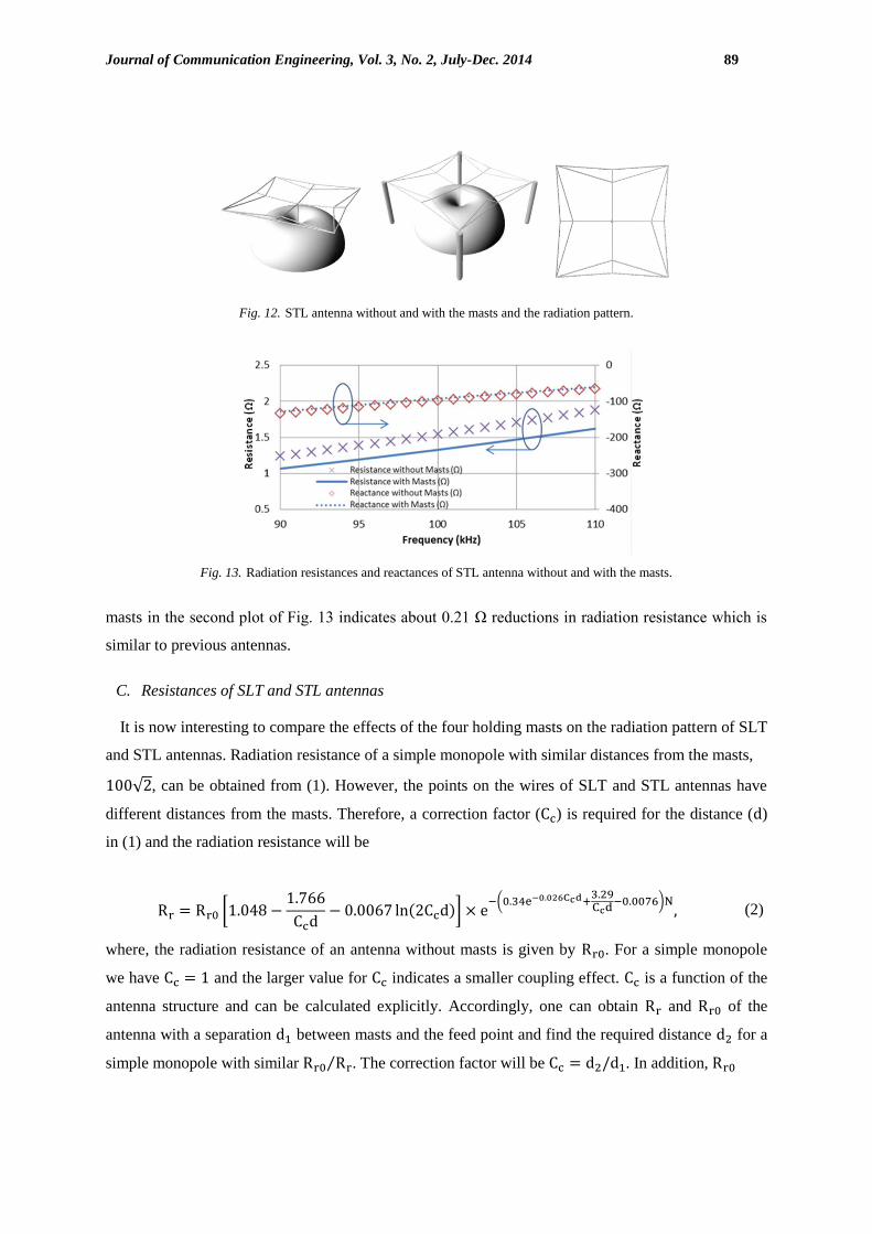
Fig. 12. STL antenna without and with the masts and the radiation pattern.
Fig. 13. Radiation resistances and reactances of STL antenna without and with the masts.
masts in the second plot of Fig. 13 indicates about 0.21 Ω reductions in radiation resistance which is
similar to previous antennas.
C. Resistances of SLT and STL antennas
It is now interesting to compare the effects of the four holding masts on the radiation pattern of SLT
and STL antennas. Radiation resistance of a simple monopole with similar distances from the masts,
√ , can be obtained from (1). However, the points on the wires of SLT and STL antennas have
different distances from the masts. Therefore, a correction factor ( ) is required for the distance ( )
in (1) and the radiation resistance will be
[
]
(
) (2)
where, the radiation resistance of an antenna without masts is given by . For a simple monopole
we have and the larger value for indicates a smaller coupling effect. is a function of the
antenna structure and can be calculated explicitly. Accordingly, one can obtain and of the
antenna with a separation between masts and the feed point and find the required distance for a
simple monopole with similar ⁄ . The correction factor will be . In addition,
90 Coupling Effects and Performance of Loran ...
(a)
(b)
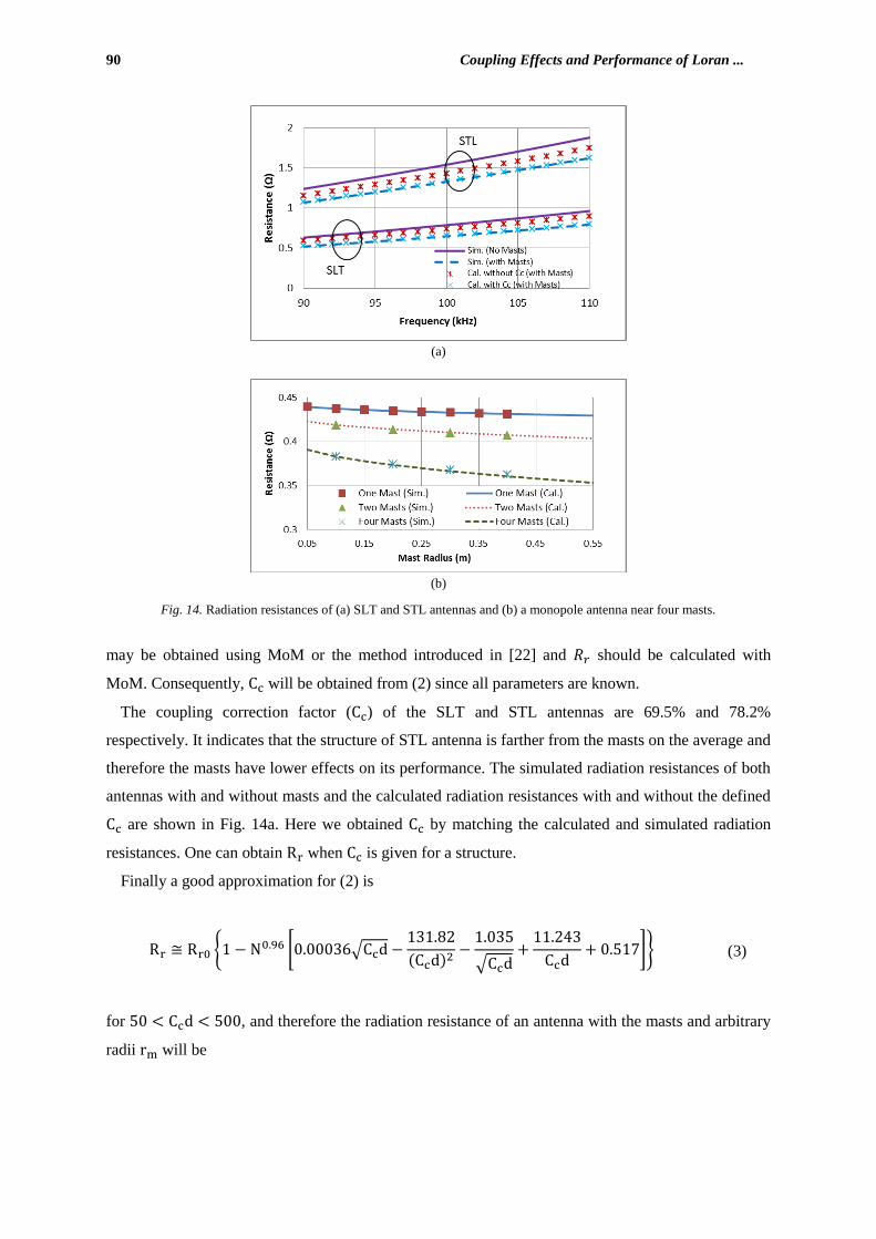
Fig. 14. Radiation resistances of (a) SLT and STL antennas and (b) a monopole antenna near four masts.
may be obtained using MoM or the method introduced in [22] and should be calculated with
MoM. Consequently, will be obtained from (2) since all parameters are known.
The coupling correction factor ( ) of the SLT and STL antennas are 69.5% and 78.2%
respectively. It indicates that the structure of STL antenna is farther from the masts on the average and
therefore the masts have lower effects on its performance. The simulated radiation resistances of both
antennas with and without masts and the calculated radiation resistances with and without the defined
are shown in Fig. 14a. Here we obtained by matching the calculated and simulated radiation
resistances. One can obtain when is given for a structure.
Finally a good approximation for (2) is
{ [ √
√
]} (3)
for , and therefore the radiation resistance of an antenna with the masts and arbitrary
radii will be

Journal of Communication Engineering, Vol. 3, No. 2, July-Dec. 2014 91
(a)
(b)
Fig. 15. FEKO radiation resistances and reactances of STL antenna (a) without and (b) with the masts compared with NEC
results.
{ [√ [ √
]
√
√
]}
(4)
using the same method as for (1). The comparison with simulated results of a simple monopole is
shown in Fig. 14b. The effect of is similar to (2) and the distances of the masts are the same as the
discussed SLT and STL antennas ( √ ) which yield
[ ( √
√ )] (5)
An example of the applications of calculating is to obtain the radiation resistance of an antenna
with the masts and arbitrary radii using (3) and the obtained from one given radius.
D. Ground effect on STL antenna
The effect of lossy ground on the performance of the STL antenna is discussed in this part. FEKO is
used for the simulations to provide another validation for the presented results from calculations and

92 Coupling Effects and Performance of Loran ...
(a)
(b)
Fig. 16. FEKO simulation results of STL antenna on lossy ground ( and ) (a) antenna
resistance (b) efficiency.
Fig. 17. FEKO radiation patterns of STL antenna on lossy ground with and S/m respectively.
NEC simulations. Radiation resistances and reactances of the STL antenna without and with the
masts are indicated in Fig. 15. The results are in agreement with the NEC result in Fig. 13.
Journal of Communication Engineering, Vol. 3, No. 2, July-Dec. 2014 93
If we consider the ground loss the antenna resistance increases. For example, the antenna resistance
on a ground with and S/m are indicated in Fig. 16 (a). As can be
observed in Fig. 16 (a), the ground loss increases the resistance, significantly. Therefore the antenna
efficiency reduces as indicated in Fig. 16 (b). However, the ground conductivity can be increased by
placing a wire grid on the ground. A suitable wire grid can increase the efficiency almost up to the
PEC ground. Finally, the effect of ground loss on the radiation pattern is indicated in Fig. 17. It can be
observed that the ground loss decreases the low angle radiation that should be compensated by using
the wire grid as well.
IV. CONCLUSION
In this paper some practical considerations are discussed for the Loran transmitter antennas. In
particular, some new insights are achieved for this relatively old topic: 1) The coupling effects of one
or multiple masts near a monopole antenna are discussed and illustrated in some plots; explicit
equations are obtained for resistance and reactance of a monopole in the vicinity of conductive masts.
2) The effects of practical neighboring conductors near some types of Loran transmitter antennas are
studied and it is shown that they affect the antenna performance significantly; some new methods are
proposed for reducing the effect of conductors. 3) It is indicated that the masts decrease the
performance of STL antenna less than SLT antenna. In addition, the effect of ground loss is studied on
the antenna resistance, efficiency and radiation pattern.
REFERENCES
[1] N. Bowditch, “The American Practical Navigator,” Washington, WA, USA, US Government Printing Office, 1995.
[2] W. Blanchard, "Hyperbolic Airborne Radio Navigation Aids," The Journal of Navigation, vol. 44, pp. 285-315, 1991.
[3] C.A. Balanis, “Antenna Theory Analysis and Design,” New York, Wiley, 2005.
[4] H. Jasik, “Antenna Engineering Handbook,” New York, McGraw Hill, 1960.
[5] A. Stadler, "Radiated magnetic field of a low-frequency ferrite rod antenna," Compatibility and Power Electronics
(CPE), 7th International Conference-Workshop. IEEE, 2011.
[6] M. Ishii and Y. Shimada, “Reference Calibration Methods for Small Circular Loop Antenna in Low-Frequency Band,”
IEEE Trans. Instrumentation Measurement, vol. 58, pp. 1097-1103, 2009.
[7] R. Barr, W. Ireland and M.J. Smith, “ELF, VLF and LF radiation from a very large loop antenna with a mountain core,”
IEE Proceedings-II, vol. 140, pp. 129-134, 1993.
[8] X. Liu, G. Wang and W. Wang, “Design and Performance of TEM Horn Antenna with Low-Frequency Compensation,”
in IEEE Conference, Proceedings. Asia-Pacific, 2003.
[9] R. Strobbe, “Antennas for 136kHz,” available from www.strobbe.eu/on7yd/136ant, 2009.
[10] R. Araneo and S. Celozzi, “FE Analysis of a Low-Frequency Microstrip Antenna,” IEEE Trans. Magnetics, vol. 38, pp.
729-732, 2002,.
[11] V. Trainotti and L.A. Dorado, “Short low and medium frequency antenna performance,” IEEE Antennas Propag. Mag.,
vol. 47, pp. 66–90, 2005.

94 Coupling Effects and Performance of Loran ...
[12] H.R. Bhojwani and L.W. Zelby, “Spiral Top-Loaded Antenna: Characteristics and Design,” IEEE Trans. Antennas
Propag., vol. AP-21, pp. 293-298, 1973.
[13] D. E. Hurdsman, P. M. Hansen, J. W. Rockway, “LF and VLF Antenna Modeling,” in IEEE Conference, Antennas
Propag. Society International Symposium, 2003.
[14] N. Paravastu, B. Hicks, P. Ray and W. Erickson, “A Candidate Active Antenna Design for a Low Frequency Radio
Telescope Array,” in IEEE Conference, Antennas Propag. Society International Symposium, 2007.
[15] J.P. Casey and R. Bansal, “Analysis and Optimization of an Electrically Small Receiving Antenna,” IEEE Trans.
Electromag. Comp., vol. 33, pp. 197-204, 1991.
[16] V. Trainotti and G. Figueroa, “Vertically Polarized Dipoles and Monopoles, Directivity, Effective Height and Antenna
Factor,” IEEE Trans. on Broadcasting, vol. 56, pp. 379-409, 2010.
[17] K. Paran,K., M. Kamyab and N. Ahmadi Tabatabaei, "FDTD analysis of top-hat monopole antennas loaded with
radially layered dielectric." International Journal of Engineering-Transactions A: Basics vol. 17, pp 251-262, 2004.
[18] F. Taheri and S. Ostadzadeh, “Transient Analysis of the Single-Conductor Overhead Lines Connected to Grid-
Grounded Arrester under Direct Lightning by Means of GA,” Journal of Communication Engineering, vol. 3, no. 1, pp.
45-54, Jan.-June 2014.
[19] P.C. Gailey, “Modeling and Measurement of Electromagnetic Fields Near LORAN-C and OMEGA Stations.” EC Corp
OAK RIDGE TN, 1987.
[20] E.K. Miller, F. J. Dedrick and W.O. Henry, “Computer Evaluation of Large low-frequency Antennas,” IEEE Trans.
Antennas Propag., vol. 21, pp. 386-390, 1973.
[21] Stout, Chris, and Charles Schue. "Designing, developing, and deploying a small footprint Low Frequency System for
Positioning, Navigation, Timing, and Data services," Position Location and Navigation Symposium (PLANS),
IEEE/ION., 2010.
[22] M. Fartookzadeh, S.H. Mohseni Armaki, S.M.J Razavi, and J. Rashed-Mohassel, "Fast method for the calculation of
radiation resistance of a catenary element antenna applied to the optimization of a Loran transmitter antenna and a
scaled model fabrication," Journal of Electromagnetic Waves and Applications, vol. 28, pp. 1044-1055, 2014.
[23] M. Fartookzadeh, S.H. Mohseni Armaki, S.M.J. Razavi, and J. Rashed-Mohassel, “Modification of Square Top Loaded
Low Frequency Antennas with Investigations on Catenary Networks Analysis,” Journal of Electromagnetic Waves and
Applications, vol. 29, pp. 92-103, 2014.
[24] A. Voors, 4nec2, available from www.qsl.net/4nec2.