Coupled Triboelectric Nanogenerator Networks for … · Coupled Triboelectric Nanogenerator...
10
Coupled Triboelectric Nanogenerator Networks for Efficient Water Wave Energy Harvesting Liang Xu, †,‡,# Tao Jiang, †,‡,# Pei Lin, †,‡,# Jia Jia Shao, †,‡ Chuan He, †,‡ Wei Zhong, †,‡ Xiang Yu Chen, †,‡ and Zhong Lin Wang* ,†,‡,§ † Beijing Institute of Nanoenergy and Nanosystems, Chinese Academy of Sciences, Beijing 100083, P. R. China ‡ College of Nanoscience and Technology, University of Chinese Academy of Sciences, Beijing 100049, P. R. China § School of Material Science and Engineering, Georgia Institute of Technology, Atlanta, Georgia 30332, United States * S Supporting Information ABSTRACT: Water wave energy is a promising clean energy source, which is abundant but hard to scavenge economically. Triboelectric nanogenerator (TENG) networks provide an effective approach toward massive harvesting of water wave energy in oceans. In this work, a coupling design in TENG networks for such purposes is reported. The charge output of the rationally linked units is over 10 times of that without linkage. TENG networks of three different connecting methods are fabricated and show better performance for the ones with flexible connections. The network is based on an optimized ball-shell structured TENG unit with high responsivity to small agitations. The dynamic behavior of single and multiple TENG units is also investigated comprehensively to fully understand their performance in water. The study shows that a rational design on the linkage among the units could be an effective strategy for TENG clusters to operate collaboratively for reaching a higher performance. KEYWORDS: triboelectric nanogenerator networks, water wave energy harvesting, coupling behavior, ball-shell structure, blue energy A s threatened by climate change and resource crisis, developing renewable and clean energy has been a focused goal for the world. 1-3 Water wave energy is a promising clean energy source that is especially abundant in the ocean. The power from waves around the coastlines worldwide was estimated to be over 2 TW (1 TW = 10 12 W). 4,5 Although having explored for decades, there still lack economical technologies to extract water wave energy at a large-scale. 6-8 Current machines usually have complex hydraulic or mechan- ical structures to catch wave energy and convert it into rotary motion or linear reciprocal motion for driving an electro- magnetic generator. 9-11 Such designs make the whole device complicated, heavy, and costly. More importantly, the conversion efficiency is so low at low rotation frequency. 12 The concept of using triboelectric nanogenerator (TENG) networks was first proposed by Wang in 2014, and it shows another route toward the goal to harness water wave energy. 13,14 The TENG, as driven by the Maxwell’s displace- ment current, can effectively convert mechanical energy into electricity based on the conjugation of tribo-electrification and electrostatic induction. 15,16 Since its birth, TENGs with different structures have demonstrated versatile abilities to harvest mechanical energy from various sources especially at low frequency, such as wind, human walking, infrastructure vibration, etc. 12,17-22 Among various mechanical energy harvesting technologies, it has the merits of simple structure, large design flexibility, abundant choices of materials, and low cost. 16,23-28 These features render the TENG networks to be a viable technology to catch water waves that are of low frequency. 14 Several TENG prototypes have been fabricated and demonstrated effective harvesting of water wave energy. 5,29-34 Nevertheless, the present works mainly focus on the structure and performance optimization of single devices, while the TENG network still remains to be experimented. In this work, TENG networks based on an optimized ball- shell structured unit are reported. First, we demonstrate a TENG unit using treated silicone rubber as triboelectric materials, which gives a high output at small agitations. The dynamic behavior and angular dependence under harmonic and impact agitations are studied comprehensively to obtain a full Received: December 7, 2017 Accepted: January 12, 2018 Published: January 12, 2018 Article www.acsnano.org Cite This: ACS Nano XXXX, XXX, XXX-XXX © XXXX American Chemical Society A DOI: 10.1021/acsnano.7b08674 ACS Nano XXXX, XXX, XXX-XXX
Transcript of Coupled Triboelectric Nanogenerator Networks for … · Coupled Triboelectric Nanogenerator...

Coupled Triboelectric NanogeneratorNetworks for Efficient Water Wave EnergyHarvestingLiang Xu,†,‡,# Tao Jiang,†,‡,# Pei Lin,†,‡,# Jia Jia Shao,†,‡ Chuan He,†,‡ Wei Zhong,†,‡ Xiang Yu Chen,†,‡
and Zhong Lin Wang*,†,‡,§
†Beijing Institute of Nanoenergy and Nanosystems, Chinese Academy of Sciences, Beijing 100083, P. R. China‡College of Nanoscience and Technology, University of Chinese Academy of Sciences, Beijing 100049, P. R. China§School of Material Science and Engineering, Georgia Institute of Technology, Atlanta, Georgia 30332, United States
*S Supporting Information
ABSTRACT: Water wave energy is a promising clean energy source, whichis abundant but hard to scavenge economically. Triboelectric nanogenerator(TENG) networks provide an effective approach toward massive harvestingof water wave energy in oceans. In this work, a coupling design in TENGnetworks for such purposes is reported. The charge output of the rationallylinked units is over 10 times of that without linkage. TENG networks ofthree different connecting methods are fabricated and show betterperformance for the ones with flexible connections. The network is basedon an optimized ball-shell structured TENG unit with high responsivity tosmall agitations. The dynamic behavior of single and multiple TENG units isalso investigated comprehensively to fully understand their performance inwater. The study shows that a rational design on the linkage among the unitscould be an effective strategy for TENG clusters to operate collaborativelyfor reaching a higher performance.
KEYWORDS: triboelectric nanogenerator networks, water wave energy harvesting, coupling behavior, ball-shell structure, blue energy
As threatened by climate change and resource crisis,developing renewable and clean energy has been afocused goal for the world.1−3 Water wave energy is a
promising clean energy source that is especially abundant in theocean. The power from waves around the coastlines worldwidewas estimated to be over 2 TW (1 TW = 1012 W).4,5 Althoughhaving explored for decades, there still lack economicaltechnologies to extract water wave energy at a large-scale.6−8
Current machines usually have complex hydraulic or mechan-ical structures to catch wave energy and convert it into rotarymotion or linear reciprocal motion for driving an electro-magnetic generator.9−11 Such designs make the whole devicecomplicated, heavy, and costly. More importantly, theconversion efficiency is so low at low rotation frequency.12
The concept of using triboelectric nanogenerator (TENG)networks was first proposed by Wang in 2014, and it showsanother route toward the goal to harness water waveenergy.13,14 The TENG, as driven by the Maxwell’s displace-ment current, can effectively convert mechanical energy intoelectricity based on the conjugation of tribo-electrification andelectrostatic induction.15,16 Since its birth, TENGs withdifferent structures have demonstrated versatile abilities toharvest mechanical energy from various sources especially at
low frequency, such as wind, human walking, infrastructurevibration, etc.12,17−22 Among various mechanical energyharvesting technologies, it has the merits of simple structure,large design flexibility, abundant choices of materials, and lowcost.16,23−28 These features render the TENG networks to be aviable technology to catch water waves that are of lowfrequency.14 Several TENG prototypes have been fabricatedand demonstrated effective harvesting of water waveenergy.5,29−34 Nevertheless, the present works mainly focuson the structure and performance optimization of singledevices, while the TENG network still remains to beexperimented.In this work, TENG networks based on an optimized ball-
shell structured unit are reported. First, we demonstrate aTENG unit using treated silicone rubber as triboelectricmaterials, which gives a high output at small agitations. Thedynamic behavior and angular dependence under harmonic andimpact agitations are studied comprehensively to obtain a full
Received: December 7, 2017Accepted: January 12, 2018Published: January 12, 2018
Artic
lewww.acsnano.orgCite This: ACS Nano XXXX, XXX, XXX−XXX
© XXXX American Chemical Society A DOI: 10.1021/acsnano.7b08674ACS Nano XXXX, XXX, XXX−XXX

understanding of such kinds of TENG units. The aggregatedperformance of multiple TENG units is also investigated, andquasi-continuous direct current can be observed for groups ofTENGs. Based on these, a coupling behavior for units linkedwith each other in TENG networks is presented. The chargeoutput for rationally designed coupled units is over 10 times ofthat without coupling. TENG networks with three differentconnection methods were fabricated and characterized; theones with flexible connections show higher efficiency. Thecoupled TENG network is an effective way to harvest waterwave energy, which is a direction for future development forblue energy.
RESULTS AND DISCUSSION
Structure and Working Principle. A photograph of a splitball-shell structured TENG (BS-TENG) unit is shown inFigure 1a, and Figure 1e illustrates its detailed structure. TheTENG unit consists of one ball and two semispherical shellswith metal electrodes and dielectric layers on their innersurfaces. Figure 1c and d shows a group of fabricated balls andshells. Here, silicone rubber was used to prepare the ball andthe dielectric layer, where its softness would enhance the realcontact area and contribute to the durability of the device.Ultraviolet (UV) treatment was applied to the ball, which has amodification effect to the surface as shown in Figure 1g; theFourier transform infrared (FTIR) spectra of the original and
the UV treated silicone rubber indicate decreased bandintensity characteristic of the Si−O−Si signal (band 4 notedin the figure), accompanied by weakened Si-CH3 signal (band1) and enhanced Si−OH signals (bands 2 and 3) after thetreatment, implying Si−O−Si chain scission and oxidativeconversion of radical groups.35 This seems to introduce adifference in the affinity to electrons for the ball and thedielectric layer, manifesting a strong tribo-electrification effectin the context of good surface contact (Figure 1h). To furtherenhance the contact electrification, polyformaldehyde (POM)particles were mixed into the dielectric layer, fabricatingmicrostructures on the surface,36,37 as shown in Figure 1b(bare silicone rubber surface is shown in Figure S1 forcomparison). The UV treatment and the microstructures alsomake the surface less sticky,38 enabling smooth roll of the ballon the dielectric layer with relative low damping force, which iscrucial for the performance of the TENG unit agitated by slowwater waves. The electrodes were fabricated by paintingcommercial Ag-Cu conductive paint on the inner surface ofthe shell.The operation mechanism of the BS-TENG unit is mainly
based on the conjugation of tribo-electrification and electro-static induction.17 As shown in Figure 1f, when the ball rolls inthe spherical shell, the surfaces of the dielectric layer and theball would be tribo-electrified, with static charges of the sameamount and opposite signs. Accompanying the back and forth
Figure 1. Structure and working principle of the TENG unit. (a, c, d) Photographs of a split ball-shell structured TENG unit, silicone rubberballs, and outer shells. (b) SEM image of silicone rubber mixed with POM particles. (e) Schematic structure of the TENG unit. (f) Workingprinciple of the TENG unit. (g) FTIR spectra of the UV treated and the original balls. (h) Tribo-electrification performance for different pairsof the ball and the shell under the same harmonic agitation.
ACS Nano Article
DOI: 10.1021/acsnano.7b08674ACS Nano XXXX, XXX, XXX−XXX
B
movement of the ball, the positive charges on its surface wouldinduce negative charges to flow between the two electrodes onthe shell through an external circuit, generating alternatecurrent in the circuit. To stimulate the roll of the ball in theshell, various mechanical agitations can be adopted, like rotateor linearly shake the shell. Such mechanism of the device can beclassified into the freestanding triboelectric layer mode,17,39
where the ball acts as the freestanding layer.Characterization of a Single TENG Unit. To compre-
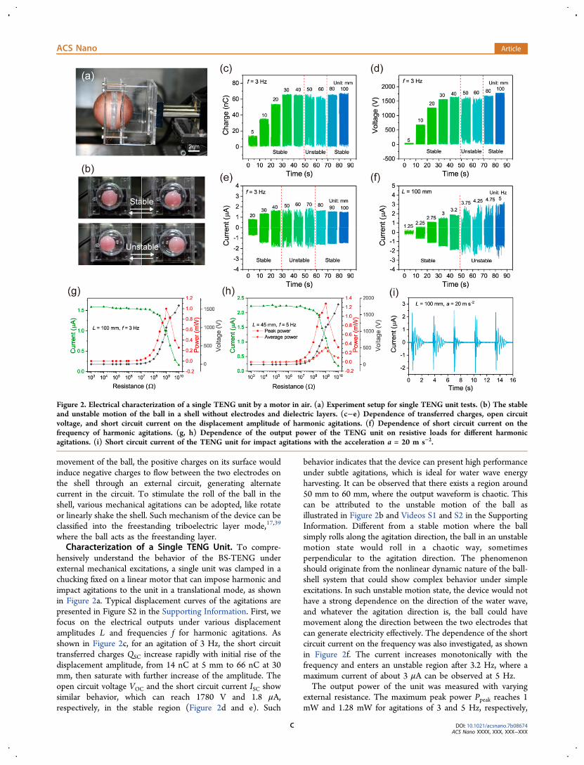
hensively understand the behavior of the BS-TENG underexternal mechanical excitations, a single unit was clamped in achucking fixed on a linear motor that can impose harmonic andimpact agitations to the unit in a translational mode, as shownin Figure 2a. Typical displacement curves of the agitations arepresented in Figure S2 in the Supporting Information. First, wefocus on the electrical outputs under various displacementamplitudes L and frequencies f for harmonic agitations. Asshown in Figure 2c, for an agitation of 3 Hz, the short circuittransferred charges QSC increase rapidly with initial rise of thedisplacement amplitude, from 14 nC at 5 mm to 66 nC at 30mm, then saturate with further increase of the amplitude. Theopen circuit voltage VOC and the short circuit current ISC showsimilar behavior, which can reach 1780 V and 1.8 μA,respectively, in the stable region (Figure 2d and e). Such
behavior indicates that the device can present high performanceunder subtle agitations, which is ideal for water wave energyharvesting. It can be observed that there exists a region around50 mm to 60 mm, where the output waveform is chaotic. Thiscan be attributed to the unstable motion of the ball asillustrated in Figure 2b and Videos S1 and S2 in the SupportingInformation. Different from a stable motion where the ballsimply rolls along the agitation direction, the ball in an unstablemotion state would roll in a chaotic way, sometimesperpendicular to the agitation direction. The phenomenonshould originate from the nonlinear dynamic nature of the ball-shell system that could show complex behavior under simpleexcitations. In such unstable motion state, the device would nothave a strong dependence on the direction of the water wave,and whatever the agitation direction is, the ball could havemovement along the direction between the two electrodes thatcan generate electricity effectively. The dependence of the shortcircuit current on the frequency was also investigated, as shownin Figure 2f. The current increases monotonically with thefrequency and enters an unstable region after 3.2 Hz, where amaximum current of about 3 μA can be observed at 5 Hz.The output power of the unit was measured with varying
external resistance. The maximum peak power Ppeak reaches 1mW and 1.28 mW for agitations of 3 and 5 Hz, respectively,
Figure 2. Electrical characterization of a single TENG unit by a motor in air. (a) Experiment setup for single TENG unit tests. (b) The stableand unstable motion of the ball in a shell without electrodes and dielectric layers. (c−e) Dependence of transferred charges, open circuitvoltage, and short circuit current on the displacement amplitude of harmonic agitations. (f) Dependence of short circuit current on thefrequency of harmonic agitations. (g, h) Dependence of the output power of the TENG unit on resistive loads for different harmonicagitations. (i) Short circuit current of the TENG unit for impact agitations with the acceleration a = 20 m s−2.
ACS Nano Article
DOI: 10.1021/acsnano.7b08674ACS Nano XXXX, XXX, XXX−XXX
C
with matched resistance of around 1 GΩ (Figure 2g and h).The high matched resistance should originate from the lowinherent capacitance of the device.28,40 We also calculated theaverage power Pave for the 5 Hz case, using the followingequation:28,40
∫=
+
PI Rdt
Tt
t T
ave0
0 2
(1)
where R represents the resistive load, I is the correspondingcurrent, and T is the period of the current waveform. Amaximum average power of 0.31 mW can be obtained withmatched resistance, which is about 24% of the peak power.Here, the average power shows less decay relative to the peakpower, since the TENG is in freestanding triboelectric modewhere single current pulses have much longer durationcompared to the vertical contact-separation mode.40,41
Under impact agitations, a short circuit current of 2.4 μA canbe obtained (Figure 2i), and the ball will oscillate to outputabout 10 pulses of current after single impacts. This shows thatthe device can store the mechanical energy and continuouslytranslate it into electricity through internal vibrations afterward.While in operation, the soft surface of the inner ball prohibits
the ball from violently colliding with the shell. Thus, the deviceis expected to have excellent durability. A TENG unit tested forseveral days can still have very stable output without any decay
in our experiments, and an 1 h continuous test is shown inFigure S3 in the Supporting Information.The exact matching between the water wave propagation
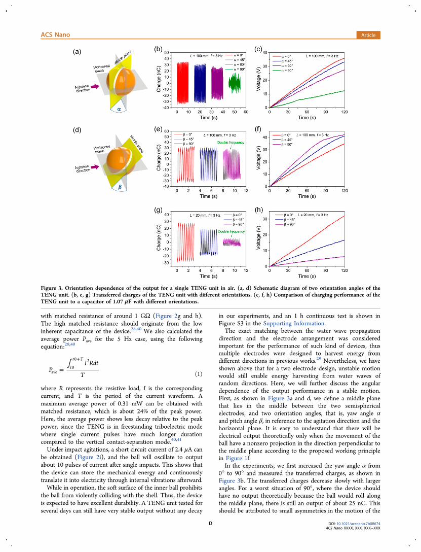
direction and the electrode arrangement was consideredimportant for the performance of such kind of devices, thusmultiple electrodes were designed to harvest energy fromdifferent directions in previous works.29 Nevertheless, we haveshown above that for a two electrode design, unstable motionwould still enable energy harvesting from water waves ofrandom directions. Here, we will further discuss the angulardependence of the output performance in a stable motion.First, as shown in Figure 3a and d, we define a middle planethat lies in the middle between the two semisphericalelectrodes, and two orientation angles, that is, yaw angle αand pitch angle β, in reference to the agitation direction and thehorizontal plane. It is easy to understand that there will beelectrical output theoretically only when the movement of theball have a nonzero projection in the direction perpendicular tothe middle plane according to the proposed working principlein Figure 1f.In the experiments, we first increased the yaw angle α from
0° to 90° and measured the transferred charges, as shown inFigure 3b. The transferred charges decrease slowly with largerangles. For a worst situation of 90°, where the device shouldhave no output theoretically because the ball would roll alongthe middle plane, there is still an output of about 25 nC. Thisshould be attributed to small asymmetries in the motion of the
Figure 3. Orientation dependence of the output for a single TENG unit in air. (a, d) Schematic diagram of two orientation angles of theTENG unit. (b, e, g) Transferred charges of the TENG unit with different orientations. (c, f, h) Comparison of charging performance of theTENG unit to a capacitor of 1.07 μF with different orientations.
ACS Nano Article
DOI: 10.1021/acsnano.7b08674ACS Nano XXXX, XXX, XXX−XXX
D

ball to the middle plane and the sensitive response of the deviceto subtle agitations as shown in Figure 2c. We also charged acapacitor of 1.07 μF to get a reliable comparison of theaccumulative output charges, which shows similar trend, andthe charging rate is about 77% for 60° and 35% for 90°, ascompared to the data at 0° (Figure 3c), indicating that thedevice with simple two-electrode design can have excellentenergy harvesting performance for water waves from mostdirections.For the pitch angle β, although the transferred charges
reduce from 64 nC at 0° to 54 nC at 90°, the fluctuationfrequency of charge output shows an unexpected doublingeffect at 90°. As a result, the charging rate is even higher at 90°than at 0° (Figure 3e and f). This is due to the relative motionbehavior of the ball to the electrodes; when the pitch angle is90°, the middle plane would coincide with the horizontal plane,and the ball would have two chances to move back and forth tothe upper electrode in a single roll cycle, producing two pulsesof output. For a smaller amplitude of the drive motion, the
transferred charges would decrease much faster for 90° (Figure3g), thus although there is still a double frequency effect, thecharging rate at 90° is much lower than at 0°, as shown inFigure 3h. For the rest of the report, the yaw angle and thepitch angle are both set to 0° unless otherwise specified.
Characterization of a Rigid Network. For the applicationof water wave energy scavenging, TENG networks are requiredfor large-scale energy harvesting.5,13,14 To understand thedependence of the output on the amount of TENG units andthe performance of TENG groups, a 4 × 4 TENG array wasfabricated, where the units were mechanically connected byrigid acrylic plates, as shown in Figure 4a. The electricalconnection of the array is shown in Figure 4b. Considering itdoes not necessarily have the same phase, the output of eachunit is rectified first, and all of them are connected in parallel.The array was tested with harmonic agitations and impact
agitations, respectively. We first tested the transferred chargesof each unit without rectification under harmonic agitations, asshown in Figure 4c. The performance of each unit shows good
Figure 4. Electrical characterization of the 4 × 4 TENG array in air. (a) Photograph of the 4 × 4 TENG array. (b) Schematic diagram of therectification circuit for the array. (c−g) Output of the TENG array for harmonic agitations with L = 40 mm and f = 3 Hz: (c) is transferredcharges for each TENG unit in the array, (e) shows rectified short circuit current with different amounts of TENG units, and (d, f, g) showcharge output, short circuit current, and open circuit voltage of the array with rectification. The TENG units are numbered as noted in (c) and(e). (h, i) Rectified short circuit current of the array under impact agitations of different accelerations and frequencies. (j, k) Dependence ofthe output power of the array on resistive loads for harmonic agitations and impact agitations, respectively. (l) Charging performance of thearray for different capacitors with harmonic agitations.
ACS Nano Article
DOI: 10.1021/acsnano.7b08674ACS Nano XXXX, XXX, XXX−XXX
E

uniformity, with an average value of 66.9 nC and a maximum of72.6 nC, which is about 3 times as high as the highest valuereported.29 The rectified total transferred charges of 16 unitsfor a single cycle QSC,16 can be calculated as 2.138 μC fromFigure 4d. The value is almost precisely the add-up of theoutput from each single unit in Figure 4c multiplying by afactor of 2 due to the rectification effect. The short circuitcurrent shows a linear dependence on the amount of units,reaching 18.1 μA for 16 parallel connected units, as shown inFigure 4e and f. This is reasonable considering that the currentis related to the rate of charge transfer:
=IdQ
dtSC,nSC,n
(2)
where ISC,n and QSC,n represent short circuit current andtransferred charges of n units, respectively. In the present array,the rigid connection makes the ball in each unit roll in roughlythe same pace, thus with the linear increase of QSC,n by n, ISC,nwill also increase linearly. The measured open circuit voltage ofthe array VOC,16 is about 1020 V (Figure 4g), which is lowerthan the voltage of a single unit mentioned above. This couldpossibly be attributed to the adoption of the rectifier. The chipused here has a maximum blocking voltage of about 1000 V,thus it cannot reliably hold a higher voltage between thepositive and the negative pins due to a rapid increasing reversecurrent in internal diodes with higher voltage. Because the opencircuit state with a high voltage is not used for applications here,
we still use this rectifier in the research for its low cost andcommercial availability.The performance of the array under impact agitations is
shown in Figure 4h and i. While the acceleration of agitations aincreases, the peak short circuit current also rises almost linearlyand achieves 34.5 μA with an acceleration of 10 m s−2. For eachcurrent pulse, there is a long tail lasting about 1.8 s, where thecurrent gradually decays to zero (Figure 4h). Due to suchcurrent tails, with shorter impact intervals, the current pulsescorresponding to successive impacts would have influence witheach other and finally present a continuous current of about 3μA in addition to a fluctuating one, as shown in Figure 4i.The output power for different resistive loads was measured
under harmonic and impact agitations, respectively. Forharmonic agitations, the measured data show a maximumpeak power of 5.93 mW at 52.88 MΩ (Figure 4j), and amaximum average power of 2.04 mW (0.128 mW for each unit)can be obtained at 70.5 MΩ using Equation 1. The tinydiscrepancy in the above optimum resistances could beattributed to that the average power is not just related to thepeak point of the current as the peak power.40 Whileconsidering the volume of the ball, the array produces a peakpower density of about 2.06 W m−3 and an average powerdensity of about 0.71 W m−3. If the network covers a water areaof 1 km2 and extends into 5 m in depth of water, with each unitspaced about 7.5 cm, a maximum average power of 1.51 MW isexpected to be delivered.
Figure 5. Schematic diagram and output comparison of mechanical connections for TENG units in water. (a) Schematic diagram of theexperiment setup for a single TENG unit in water. (b, c) Transferred charges and short circuit current for the TENG unit in different states.(d) Charging performance to a capacitor of 1.07 μF for the TENG unit in different states. (e, f) Schematic diagram of network connectingstrategies. (g) Force analysis for a TENG unit in the network.
ACS Nano Article
DOI: 10.1021/acsnano.7b08674ACS Nano XXXX, XXX, XXX−XXX
F

For impact agitations, as shown in Figure 4k, the measureddata show a maximum peak power of 12.83 mW, withcorresponding peak power density of 4.47 W m−3.To test the performance of the array for capacitive load,
different capacitors were charged with the array, as shown inFigure 4l. Typically, the BS-TENG array can charge a capacitorof 44.2 μF to 3 V within 22.9 s, and the stored energy can beused to power small electronics, like thermometers, anemom-eters, etc.Coupled TENG Networks in Water. The TENG network
is proposed to harvest water wave energy in a large area.5,13,14
However, it is still not clear how the network should beorganized to receive the maximum output power, and what isthe function of the networking besides harvesting energy fromdistributed local sites. In this section, we investigate TENGarrays in real water circumstances and show a coupling behaviorbetween TENG units by networking, which acts as a crucialrole for TENGs to operate effectively in water waves.In the study, wave tank experiments were carried out to test
single TENG units and 4 × 4 TENG arrays with differentnetwork connection methods. The setup of the wave tank isshown in Figure S4 in the Supporting Information. First, asillustrated in Figure 5a, two sorts of TENG units were tested,referred to as the free-unit and the linked-unit. For the free-unit, the TENG floats freely on water surface, mimicking theunit in an array with no mechanical connections. For thelinked-unit, the TENG is connected to a fixed pole above thewater surface by a polycarbonate (PC) strip of 1 cm width and
0.3 cm thickness, mimicking units with certain mechanicalcoupling to a network.The transferred charges of such units are shown in Figure 5b.
For the free TENG unit, obvious drifts of the baseline of chargeoutput can be observed, which reflect that the inner ball rolls tocertain sites without completely rolling back due to orientationchanges of the whole unit. Without effective constraints of alinkage, the orientation of the unit would vary arbitrarily,sometimes in a “dead” state where there is almost no output(Video S3 in the Supporting Information). Even in goodorientations, the transferred charges can only reach about 30nC for 2 Hz water waves. For the linked-unit, the performanceimproves significantly, with transferred charges of 63 nC and 55nC in 2 and 1 Hz water waves, respectively, and the drift of thebaseline is suppressed. The comparison shows the crucial rolesplayed by the linkage that couples TENG units for properoperation in water. Two effects can be concluded: First, theconstraint effect of the linkage helps the unit to maintain anoptimum orientation as discussed above; and second, thelinkage would transfer force and energy between units andimpose a torque to the unit accompanied by the push of waterwaves, which drives the unit to rotate and to be excitedeffectively by slow water motion. The second effect can explainwhy even both in good orientations, the output improvessubstantially for the unit in the linked state versus that in thefree state. The short circuit current shown in Figure 5c furtherconfirms the role played by the linkage. We also tested chargingperformance of the units to a capacitor of 1.07 μF, to show thelong-term charge output and suppress short-term randomness
Figure 6. Comparison of the TENG networks with three different types of connecting strategies in water. (a) Photograph of the stringconnected TENG network. (b) Imaginary picture of future large-scale TENG networks for harvesting water wave blue energy. (c, d) Rectifiedshort circuit current and transferred charges of three different types of TENG networks. (e) Charging performance of the three types ofnetworks to a capacitor of 11.2 μF. (f) Charging performance of the elastic strip connected network to different capacitors under water wavesof 2 Hz. (g) Photograph of the string connected network to power a thermometer. (h) Schematic diagram of the circuit for powering thethermometer. (i) Charging and discharging processes for a capacitor of 108 μF to power the thermometer.
ACS Nano Article
DOI: 10.1021/acsnano.7b08674ACS Nano XXXX, XXX, XXX−XXX
G

(Figure 5d). Charging curves for the free-unit show obviousplateaus where the voltage of the capacitor hardly has anyincrease for a long time. For the linked-unit, the charging ismuch faster, improving to about 11.6 times for 2 Hz waterwaves, to charge the capacitor to 7.5 V.The above data indicate that the effects of proper linkage are
musts for such TENG units to operate in water. For a group ofTENGs, the harvesting efficiency could be very low asdispersed units covering large areas without linkage. Thus,mechanical connections between units in the TENG networksto effectively couple each unit play crucial roles. In thenetworks, each unit is mechanically linked to other units, sothat the correlative mechanical movement by coupling amongthem gives a high output. To further illustrate the idea and testdifferent connections, networks with three types of connectionswere proposed, that is, rigid plate connection which will notdeform, elastic strip connection that can deform to some extent,and string connection that can freely deform without extension,as shown in Figure 5e. The connection topology is shown inFigure 5f. Details of the connection methods can be found inthe Experimental Section. Figure 5g further clarifies the effectsfrom unit coupling, using one-dimensional string connection asan example. In general, the connection can maintain the unit ina proper orientation, and meanwhile the force components atthe link points, F21y and F23y, would impose a torque to the unit,along with the interaction force from the water, making the unitrotate or vibrate.To test their performance in water, the above three types of
networks were fabricated and tested in the wave tank withsimulated water waves of frequencies 1 and 2 Hz, respectively(Figure 6a). As shown in Figure 6c, for the rigid connection, itcan reach a rectified short circuit current of 8.3 μA at 1 Hz and2.2 μA at 2 Hz. The rigid connection provides a strongconstraint for the units in the network, which makes themmove in a synchronized mode, resulting in relative large currentpeaks at 1 Hz. For 2 Hz, the wavelength and vibrationamplitude reduce dramatically, and the output decreases rapidly(Video S4 in the Supporting Information). For the cases withthe string connection and the elastic strip connection, whichcan be regarded as flexible connections, the networks performwell at both 1 and 2 Hz, and an internal vibration behaviorbetween units can be observed, as shown in Video S5 in theSupporting Information. Their current signals have similarfeatures that are composed by a continuous part of about 1 μAand a fluctuating part, with total current peaks ranging from 6μA to 7.5 μA. The rectified charge outputs are shown in Figure6d, the elastic strip connection at 2 Hz shows the highestoutput rate of 2.7 μC every second. For each unit in suchnetwork, the charge output is about 10.8 times as that for freeunits shown in Figure 5a. To observe charge outputs in longertime scale and suppress possible randomness, a capacitor of11.2 μF was charged with these networks, as shown in Figure6e. The two flexible connections have similar performance forthe same water wave frequency, with the cases at 2 Hz a bithigher than at 1 Hz. The rigid connection shows weaker outputat 1 Hz and the worst result at 2 Hz. The above experimentsindicate that flexible connections are better networkingstrategies than the rigid one which imposes too much internalconstraints between units.With excellent performance in water, the flexible networks
can charge different capacitors efficiently (Figure 6f), capable ofpowering various small electronic devices, like sensors, wirelesstransmission modules, etc. Here, we demonstrate an application
for the network to supply electricity for a thermometer tomeasure the temperature of the water. The electrical circuit isshown in Figure 6h. The output of each unit is rectified andthen parallel connected together to charge a capacitor of 108μF. After the voltage rose to about 1.5 V, the switch was closed,and the thermometer started to work to display the righttemperature of the water, as shown in Figure 6g and Video S6in the Supporting Information. The initial charging processtook only about 78 s at 2 Hz using the string connectednetwork (Figure 6i). A more profound idea is to harvest waterwave energy from large areas with scaled up TENG networks,that is, blue energy,5,13,14 as shown in Figure 6b. With couplingbetween units, the TENG network is proved to be an effectiveway to harvest water wave energy. The aggregated power ofunits in large areas can be huge. Such electricity can betransferred to the grid on land or to small islands throughsubmarine cables, providing an inexhaustible clean energysource for humans.
CONCLUSIONSIn summary, coupled TENG networks based on optimized BS-TENG units for water wave energy harvesting are reported. Arational design on the coupling among units greatly enhancesthe operating efficiency of the network. The charge output ofthe coupled units is over 10 times of that without coupling.TENG networks of three different connection methods werefabricated and characterized, with flexible connections perform-ing much better than the rigid one for extra internal degrees offreedom. The unit of the TENG network adopts a typical ball-shell structure with optimized designs that have highresponsivity to small agitations. The dynamic behavior andangular dependence under harmonic and impact agitations arestudied comprehensively to obtain a full understanding of suchkind of TENG units. The aggregated performance of multipleTENGs is also investigated, and a quasi-continuous directcurrent can be observed for groups of TENGs. The reportdemonstrates that the coupled TENG network is an effectiveway to harvest water wave energy, toward the blue energydream.
EXPERIMENTAL SECTIONFabrication of the TENG Unit. For the inner ball, the base and
the curing agent of the silicone rubber (PS6605) were mixed uniformlyby volume ratio 1:1 and then poured into a ball-shaped mold withinner diameter of 4 cm. A hollow plastic ball of 3 cm was placed in thecenter of the mold to be wrapped up by the silicone rubber. Aftercuring for 1 h at the temperature of 60 °C, a hollow silicone rubberball was prepared. The ball was then UV treated for 10 min using anUV cleaner (BZS250GF-TC). For the outer shell, Ag-Cu conductivepaint (Changyuan 6330) was painted on the inner surface of the shellwhich has a diameter of 7 cm and baked at the temperature of 60 °Cfor 0.5 h to form a tough layer of metal electrode. The silicone rubber(PS6605) was then smeared over the electrode with POM particlessprayed on and cured for 1 h at the temperature of 60 °C.
Fabrication of the Network. For the rigid plate connectednetwork, the 16 TENG units were placed between two acrylic plateswhich have 16 round holes with a diameter of 6.3 cm in a 4 × 4 array,and the TENG units were seated firmly in the holes. For the elasticstrip connected network, plastic strips with a width of 1 cm were gluedon every two neighboring TENG units to form a 4 × 4 arrangedTENG array, according to the topology shown in Figure 5f. For thestring connected network, every two neighboring TENG units in thearray were bunched with strings by a distance of about 1 cm.
Electrical Characterization. The open circuit voltage wasmeasured by an electrostatic voltmeter (Trek 344). The transferred
ACS Nano Article
DOI: 10.1021/acsnano.7b08674ACS Nano XXXX, XXX, XXX−XXX
H

charges and the current were measured by an electrometer (Keithley6514).
ASSOCIATED CONTENT*S Supporting InformationThe Supporting Information is available free of charge on theACS Publications website at DOI: 10.1021/acsnano.7b08674.
SEM images of bare silicone rubber surface; typicaldisplacement curves for agitation movement of themotor; transferred charges of the TENG unit under long-time operation; setup for wave tank experiments (PDF)Video S1: Stable motion of the ball in a shell withoutelectrodes and dielectric layers (AVI)Video S2: Unstable motion of the ball in a shell withoutelectrodes and dielectric layers (AVI)Video S3: Free TENG unit under water waves of 2 HzAVI)Video S4: Rigid network under water waves of 2 Hz(AVI)Video S5: String connected network under water wavesof 2 Hz (AVI)Video S6: Powering a thermometer by the stringconnected network (AVI)
AUTHOR INFORMATIONCorresponding Author*E-mail: [email protected] Lin Wang: 0000-0002-5530-0380Author Contributions#These authors contributed equally to this work. L. Xu and Z.L. Wang conceived the idea, analyzed the data, and preparedthe paper. L. Xu, T. Jiang, P. Lin, and W. Zhong fabricated thedevice. L. Xu, P. Lin, and C. He did the experiments. T. Jianghelped in the FEM calculation. J. J. Shao helped in the FTIRcharacterization and analysis. X. Y. Chen helped in improvingthe material. Z. L. Wang guided the whole project.NotesThe authors declare no competing financial interest.
ACKNOWLEDGMENTSWe thank Chao Ran Deng for helping render the pictures ofthree-dimensional model. Research was supported by theNational Key R & D Project from Minister of Science andTechnology, China (2016YFA0202704), National NaturalScience Foundation of China (grant nos. 51605033,51432005, 5151101243, and 51561145021), the “ThousandsTalents” Program for Pioneer Researcher and His InnovationTeam, China, China Postdoctoral Science Foundation (grantno. 2015M581041), and Beijing Municipal Science &Technology Commission (grant no. Z171100000317001).
REFERENCES(1) Schiermeier, Q.; Tollefson, J.; Scully, T.; Witze, A.; Morton, O.Electricity without Carbon. Nature 2008, 454, 816−823.(2) Gielen, D.; Boshell, F.; Saygin, D. Climate and Energy Challengesfor Materials Science. Nat. Mater. 2016, 15, 117−120.(3) Jacobson, M. Z.; Delucchi, M. A.; Bazouin, G.; Bauer, Z. A. F.;Heavey, C. C.; Fisher, E.; Morris, S. B.; Piekutowski, D. J. Y.; Vencill,T. A.; Yeskoo, T. W. 100% Clean and Renewable Wind, Water, andSunlight (WWS) All-Sector Energy Roadmaps for the 50 UnitedStates. Energy Environ. Sci. 2015, 8, 2093−2117.
(4) Khaligh, A.; Onar, O. C. Energy Harvesting: Solar, Wind, andOcean Energy Conversion Systems; CRC Press: Boca Raton, 2009; pp223−225.(5) Wang, Z. L.; Jiang, T.; Xu, L. Toward the Blue Energy Dream byTriboelectric Nanogenerator Networks. Nano Energy 2017, 39, 9−23.(6) Salter, S. H. Wave Power. Nature 1974, 249, 720−724.(7) Falcao, A. F. D. Wave Energy Utilization: A Review of theTechnologies. Renewable Sustainable Energy Rev. 2010, 14, 899−918.(8) Drew, B.; Plummer, A. R.; Sahinkaya, M. N. A Review of WaveEnergy Converter Technology. Proc. Inst. Mech. Eng., Part A 2009, 223,887−902.(9) Tollefson, J. Power from the Oceans: Blue Energy. Nature 2014,508, 302−304.(10) Callaway, E. Energy: To Catch a Wave. Nature 2007, 450, 156−159.(11) Scruggs, J.; Jacob, P. Engineering. Harvesting Ocean WaveEnergy. Science 2009, 323, 1176−1178.(12) Zi, Y. L.; Guo, H. Y.; Wen, Z.; Yeh, M. H.; Hu, C. G.; Wang, Z.L. Harvesting Low-Frequency (< 5 Hz) Irregular Mechanical Energy:A Possible Killer Application of Triboelectric Nanogenerator. ACSNano 2016, 10, 4797−4805.(13) Wang, Z. L. Triboelectric Nanogenerators as New EnergyTechnology and Self-Powered Sensors - Principles, Problems andPerspectives. Faraday Discuss. 2014, 176, 447−458.(14) Wang, Z. L. Catch Wave Power in Floating Nets. Nature 2017,542, 159−160.(15) Fan, F. R.; Tian, Z. Q.; Wang, Z. L. Flexible TriboelectricGenerator! Nano Energy 2012, 1, 328−334.(16) Wang, Z. L. On Maxwell’s Displacement Current for Energy andSensors: the Origin of Nanogenerators.Mater. Today 2017, 20, 74−82.(17) Wang, Z. L.; Chen, J.; Lin, L. Progress in TriboelectricNanogenerators as a New Energy Technology and Self-PoweredSensors. Energy Environ. Sci. 2015, 8, 2250−2282.(18) Zhu, G.; Peng, B.; Chen, J.; Jing, Q. S.; Wang, Z. L. TriboelectricNanogenerators as a New Energy Technology: From Fundamentals,Devices, to Applications. Nano Energy 2015, 14, 126−138.(19) Niu, S. M.; Wang, X. F.; Yi, F.; Zhou, Y. S.; Wang, Z. L. AUniversal Self-Charging System Driven by Random BiomechanicalEnergy for Sustainable Operation of Mobile Electronics. Nat. Commun.2015, 6, 8975.(20) Zhu, G.; Zhou, Y. S.; Bai, P.; Meng, X. S.; Jing, Q. S.; Chen, J.;Wang, Z. L. A Shape-Adaptive Thin-Film-Based Approach for 50%High-Efficiency Energy Generation Through Micro-Grating SlidingElectrification. Adv. Mater. 2014, 26, 3788−3796.(21) Zhu, G.; Su, Y. J.; Bai, P.; Chen, J.; Jing, Q. S.; Yang, W. Q.;Wang, Z. L. Harvesting Water Wave Energy by Asymmetric Screeningof Electrostatic Charges on a Nanostructured Hydrophobic Thin-FilmSurface. ACS Nano 2014, 8, 6031−6037.(22) Wang, J.; Li, S. M.; Yi, F.; Zi, Y. L.; Lin, J.; Wang, X. F.; Xu, Y.L.; Wang, Z. L. Sustainably Powering Wearable Electronics Solely byBiomechanical Energy. Nat. Commun. 2016, 7, 12744.(23) Wang, Z. L.; Song, J. H. Piezoelectric Nanogenerators Based onZinc Oxide Nanowire Arrays. Science 2006, 312, 242−246.(24) Dagdeviren, C.; Joe, P.; Tuzman, O. L.; Park, K.; Lee, K. J.; Shi,Y.; Huang, Y. G.; Rogers, J. A. Recent Progress in Flexible andStretchable Piezoelectric Devices for Mechanical Energy Harvesting,Sensing and Actuation. Extreme Mech. Lett. 2016, 9, 269−281.(25) El-hami, M.; Glynne-Jones, P.; White, N. M.; Hill, M.; Beeby, S.;James, E.; Brown, A. D.; Ross, J. N. Design and Fabrication of a NewVibration-Based Electromechanical Power Generator. Sens. Actuators,A 2001, 92, 335−342.(26) Wang, H. S.; Jeong, C. K.; Seo, M. H.; Joe, D. J.; Han, J. H.;Yoon, J. B.; Lee, K. J. Performance-Enhanced Triboelectric Nano-generator Enabled by Wafer-Scale Nanogrates of Multistep PatternDownscaling. Nano Energy 2017, 35, 415−423.(27) Zhang, C.; Tang, W.; Han, C. B.; Fan, F. R.; Wang, Z. L.Theoretical Comparison, Equivalent Transformation, and ConjunctionOperations of Electromagnetic Induction Generator and Triboelectric
ACS Nano Article
DOI: 10.1021/acsnano.7b08674ACS Nano XXXX, XXX, XXX−XXX
I

Nanogenerator for Harvesting Mechanical Energy. Adv. Mater. 2014,26, 3580−3591.(28) Niu, S. M.; Wang, Z. L. Theoretical Systems of TriboelectricNanogenerators. Nano Energy 2015, 14, 161−192.(29) Wang, X. F.; Niu, S. M.; Yin, Y. J.; Yi, F.; You, Z.; Wang, Z. L.Triboelectric Nanogenerator Based on Fully Enclosed RollingSpherical Structure for Harvesting Low-Frequency Water WaveEnergy. Adv. Energy Mater. 2015, 5, 1501467.(30) Chen, J.; Yang, J.; Li, Z. L.; Fan, X.; Zi, Y. L.; Jing, Q. S.; Guo, H.Y.; Wen, Z.; Pradel, K. C.; Niu, S. M.; Wang, Z. L. Networks ofTriboelectric Nanogenerators for Harvesting Water Wave Energy: APotential Approach toward Blue Energy. ACS Nano 2015, 9, 3324−3331.(31) Yang, Y.; Zhang, H. L.; Liu, R. Y.; Wen, X. N.; Hou, T. C.;Wang, Z. L. Fully Enclosed Triboelectric Nanogenerators forApplications in Water and Harsh Environments. Adv. Energy Mater.2013, 3, 1563−1568.(32) Zhang, L. M.; Han, C. B.; Jiang, T.; Zhou, T.; Li, X. H.; Zhang,C.; Wang, Z. L. Multilayer Wavy-Structured Robust TriboelectricNanogenerator for Harvesting Water Wave Energy. Nano Energy 2016,22, 87−94.(33) Xu, L.; Pang, Y. K.; Zhang, C.; Jiang, T.; Chen, X. Y.; Luo, J. J.;Tang, W.; Cao, X.; Wang, Z. L. Integrated Triboelectric Nano-generator Array Based on Air-Driven Membrane Structures for WaterWave Energy Harvesting. Nano Energy 2017, 31, 351−358.(34) Wen, Z.; Guo, H.; Zi, Y.; Yeh, M. H.; Wang, X.; Deng, J.; Wang,J.; Li, S.; Hu, C.; Zhu, L.; Wang, Z. L. Harvesting Broad FrequencyBand Blue Energy by a Triboelectric-Electromagnetic HybridNanogenerator. ACS Nano 2016, 10, 6526−6534.(35) Efimenko, K.; Wallace, W. E.; Genzer, J. Surface Modification ofSylgard-184 Poly(dimethyl siloxane) Networks by Ultraviolet andUltraviolet/Ozone Treatment. J. Colloid Interface Sci. 2002, 254, 306−315.(36) Yang, Y.; Zhang, H. L.; Chen, J.; Lee, S. M.; Hou, T. C.; Wang,Z. L. Simultaneously Harvesting Mechanical and Chemical Energies bya Hybrid Cell for Self-Powered Biosensors and Personal Electronics.Energy Environ. Sci. 2013, 6, 1744−1749.(37) Li, H. Y.; Su, L.; Kuang, S. Y.; Pan, C. F.; Zhu, G.; Wang, Z. L.Significant Enhancement of Triboelectric Charge Density byFluorinated Surface Modification in Nanoscale for ConvertingMechanical Energy. Adv. Funct. Mater. 2015, 25, 5691−5697.(38) Li, S. M.; Peng, W. B.; Wang, J.; Lin, L.; Zi, Y. L.; Zhang, G.;Wang, Z. L. All-Elastomer-Based Triboelectric Nanogenerator as aKeyboard Cover To Harvest Typing Energy. ACS Nano 2016, 10,7973−7981.(39) Wang, S. H.; Xie, Y. N.; Niu, S. M.; Lin, L.; Wang, Z. L.Freestanding Triboelectric-Layer-Based Nanogenerators for Harvest-ing Energy from a Moving Object or Human Motion in Contact andNon-contact Modes. Adv. Mater. 2014, 26, 2818−2824.(40) Niu, S. M.; Liu, Y.; Chen, X. Y.; Wang, S. H.; Zhou, Y. S.; Lin,L.; Xie, Y. N.; Wang, Z. L. Theory of Freestanding Triboelectric-Layer-Based Nanogenerators. Nano Energy 2015, 12, 760−774.(41) Niu, S. M.; Wang, S. H.; Lin, L.; Liu, Y.; Zhou, Y. S.; Hu, Y. F.;Wang, Z. L. Theoretical Study of Contact-Mode TriboelectricNanogenerators as an Effective Power Source. Energy Environ. Sci.2013, 6, 3576−3583.
ACS Nano Article
DOI: 10.1021/acsnano.7b08674ACS Nano XXXX, XXX, XXX−XXX
J