Counter Experiments - INFN · Counter Experiments Paolo Franzini ... GM counters with 100 ns or...
41
Counter Experiments Paolo Franzini Universit` a di Roma, La Sapienza Karlsruhe University Karlsruhe, Fall 2002
Transcript of Counter Experiments - INFN · Counter Experiments Paolo Franzini ... GM counters with 100 ns or...
Counter Experiments
Paolo Franzini
Universita di Roma, La SapienzaKarlsruhe University
Karlsruhe, Fall 2002
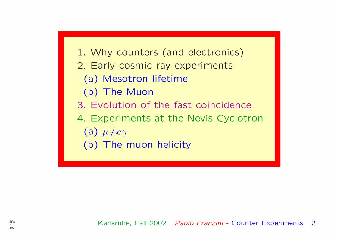
1. Why counters (and electronics)
2. Early cosmic ray experiments
(a) Mesotron lifetime
(b) The Muon
3. Evolution of the fast coincidence
4. Experiments at the Nevis Cyclotron
(a) µ→/ eγ
(b) The muon helicity
thisistex
Karlsruhe, Fall 2002 Paolo Franzini - Counter Experiments 2
While the visual impact of Wilson chamber nuclear emulsions
and bubble chambers were enormously important in the be-
ginning of elementary particle physics, there was always the
necessity of dealing with large samples of events of the same
kind.
Typical example are the measurement of a particle lifetime,
of a decay spectrum or an angular distribution in a scattering
experiment. For an accuracy at the 10−2 level one needs typ-
ically 104 events, today we can reach 10−5: τµ=(2.19703 ±0.00004) × 10−6 s.
Visual techniques then become useless, you cannot commit the
labor of hundreds of people for hundreds of years to examining
and measuring billion of pictures!!
thisistex
Karlsruhe, Fall 2002 Paolo Franzini - Counter Experiments 3
Use of counters requires however electronics. In general we
need to amplify tiny signals best defined by giving the number
of electrons
While means for counting particles were early developed few
more steps were necessary, foremost the possibility of detect-
ing some happenings in temporal coincidence. They first coin-
cidences were observed by Bothe by electromechanical means.
Rossi first introduced in 1930, the use of thermoionic valves
or vacuum tubes: triodes or pentodes if anybody ever heard
about them.
Together with the Geiger-Muller counter, the Rossi coincidence
was used in the 30’s and 40’s to study cosmic rays, em shower,
measuring the muon lifetime to ∼1% accuracy and to prove
the special properties of the muon.
thisistex
Karlsruhe, Fall 2002 Paolo Franzini - Counter Experiments 4
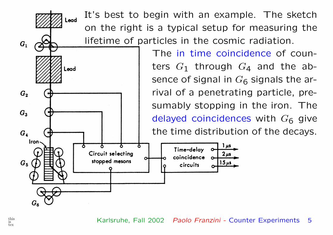
It’s best to begin with an example. The sketch
on the right is a typical setup for measuring the
lifetime of particles in the cosmic radiation.
The in time coincidence of coun-
ters G1 through G4 and the ab-
sence of signal in G6 signals the ar-
rival of a penetrating particle, pre-
sumably stopping in the iron. The
delayed coincidences with G6 give
the time distribution of the decays.
thisistex
Karlsruhe, Fall 2002 Paolo Franzini - Counter Experiments 5

In 1937 Anderson and Neddermeyer proved the existence of
a particle of mass � me, it did not radiate in a 1 cm plat-
inum plate. Street and Stevenson measured 130×me. It could
have been Yukawa’s mesotron, expected mass ∼1/rp∼200 MeV
(mµ=105 MeV). The mass is now 105.658357 MeV.
In 1947 Conversi, Pancini and Piccioni observed that the life-
time of negative muons stopped in carbon equals that of pos-
itive muons. A definitive proof that the muon is not Yukawa’s
mesotron.
During the last war years the Rome group had developed a
method to select positive and negative muons in the cosmic
radiation at sea level. This was done with the so-called mag-
netic lenses.
thisistex
Karlsruhe, Fall 2002 Paolo Franzini - Counter Experiments 6
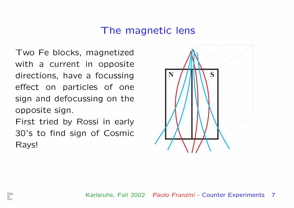
The magnetic lens
Two Fe blocks, magnetized
with a current in opposite
directions, have a focussing
effect on particles of one
sign and defocussing on the
opposite sign.
First tried by Rossi in early
30’s to find sign of Cosmic
Rays!
SN
thisistex
Karlsruhe, Fall 2002 Paolo Franzini - Counter Experiments 7

The Conversi Pancini Piccioni experiment
A late signal from
the D counters in
coincidence with
the A and B
counters delayed,
signals the arrival
of a positive
(negative) muon
which stops in the
absorber and then
decays into an
electron.
A·B·D gives a
background count.
A
B
A
D
C
DD D D D D D
B
C
C
C
C
C
AbsorberPbPb
MagnetizedFe
N '
N
thisistex
Karlsruhe, Fall 2002 Paolo Franzini - Counter Experiments 8

So what?
The muon lifetime in vacuum is 2.2 µs, measured since the
early days. This immediately tells us that the decay is due to
the weak interaction.
The Yukawa mesotrons have however strong interaction with
nucleons. This means that a mesotron interacts with a nucleon
with a reaction rate of ∼3 × 10²³ per second (s−1).
When muons come at rest in matter, (<10 ps), positive muons
can only decay as in vacuum while negative muons will bind in
hydrogen-like structures. In condensed matter, thermal muons
bind into S-wave orbits also in very short times. Mostly by
Stark effect.
thisistex
Karlsruhe, Fall 2002 Paolo Franzini - Counter Experiments 9
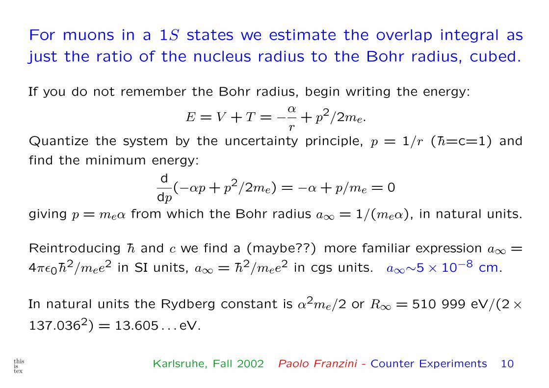
For muons in a 1S states we estimate the overlap integral as
just the ratio of the nucleus radius to the Bohr radius, cubed.
If you do not remember the Bohr radius, begin writing the energy:
E = V + T = −α
r+ p2/2me.
Quantize the system by the uncertainty principle, p = 1/r ( h=c=1) and
find the minimum energy:
d
dp(−αp + p2/2me) = −α + p/me = 0
giving p = meα from which the Bohr radius a∞ = 1/(meα), in natural units.
Reintroducing h and c we find a (maybe??) more familiar expression a∞ =
4πε0 h2/mee2 in SI units, a∞ = h2/mee2 in cgs units. a∞∼5 × 10⁻⁸ cm.
In natural units the Rydberg constant is α2me/2 or R∞ = 510 999 eV/(2×137.0362) = 13.605 . . . eV.
thisistex
Karlsruhe, Fall 2002 Paolo Franzini - Counter Experiments 10
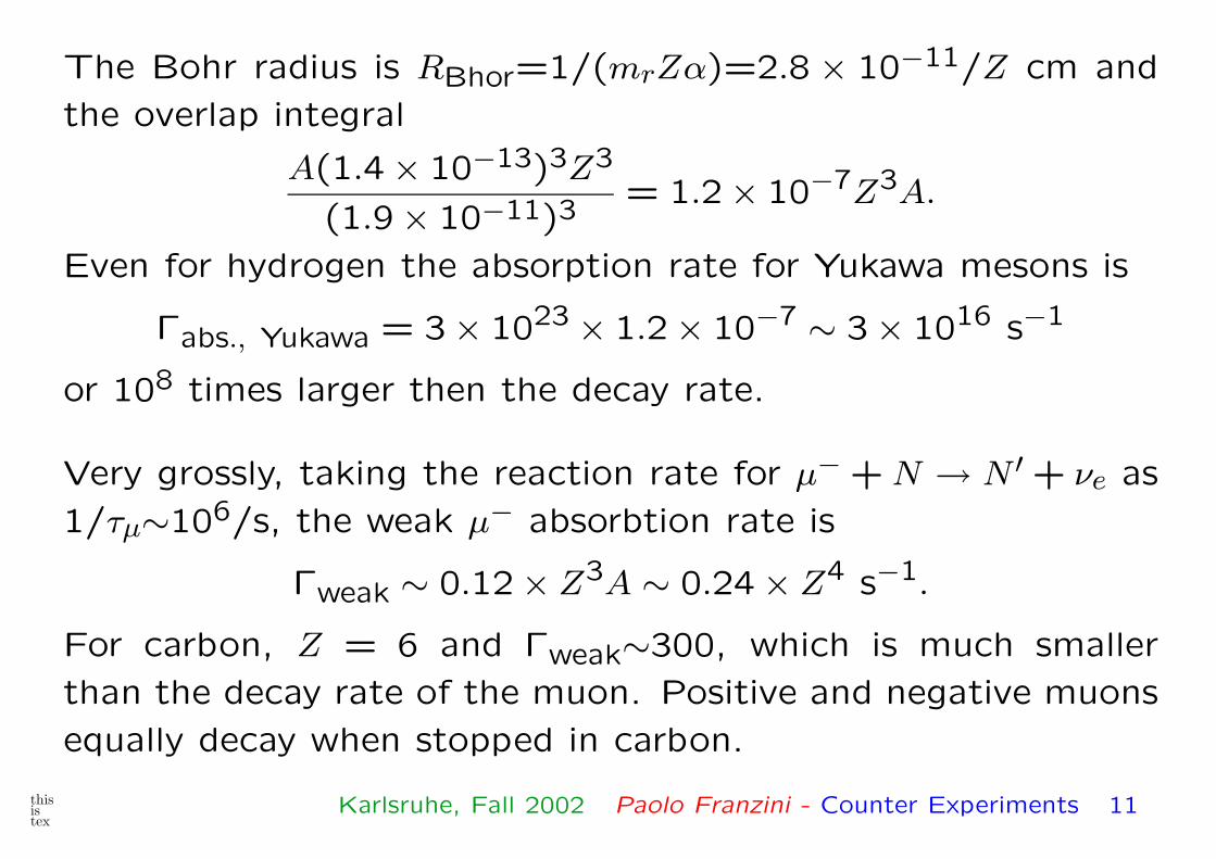
The Bohr radius is RBhor=1/(mrZα)=2.8 × 10−11/Z cm and
the overlap integral
A(1.4 × 10⁻¹³)3Z3
(1.9 × 10⁻¹¹)3= 1.2 × 10⁻⁷Z3A.
Even for hydrogen the absorption rate for Yukawa mesons is
Γabs., Yukawa = 3 × 1023 × 1.2 × 10−7 ∼ 3 × 10¹⁶ s−1
or 108 times larger then the decay rate.
Very grossly, taking the reaction rate for µ− + N → N ′ + νe as
1/τµ∼106/s, the weak µ− absorbtion rate is
Γweak ∼ 0.12 × Z3A ∼ 0.24 × Z4 s−1.
For carbon, Z = 6 and Γweak∼300, which is much smaller
than the decay rate of the muon. Positive and negative muons
equally decay when stopped in carbon.
thisistex
Karlsruhe, Fall 2002 Paolo Franzini - Counter Experiments 11
However, for Z = (106/.24)1/4∼45, the weak capture rate be-
comes significant. Conversi et al. did observe that for negative
muons stopping in Fe, Z=26, the free decay is almost not
present.
The estimates above are of course very crude. The Z3A de-
pendence of the capture rate has been however verified (later)
by measuring τµ = 1/(Γ(dec) + Γ(cap)) in different materials.
From the observation of Conversi et al. the muon was born.
The names π, µ are due to the Bristol nuclear emulsion group of
Lattes, Occhialini and Powell. The muon is a basic constituent
of the so called standard model and as best as we can tell an
elementary particle. The π-meson is the Yukawa mesotron.
thisistex
Karlsruhe, Fall 2002 Paolo Franzini - Counter Experiments 12

Evolution of counters and electronics
Geiger-Muller dominated the early days but had one basic lim-
itation. Coincidence resolving time is limited to the µs level.
This is not really a failing of the G-M tube but but is due to
the (drift) time elapsed before the initial ionization reaches the
multiplication region near the central wire.
GM counters with 100 ns or less resolving time can be built.
They go under different names, streamer tubes, etc. and are
sometimes used.
This slow drift is used today for measuring position to ∼1/10
mm accuracy in the drift chamber.
thisistex
Karlsruhe, Fall 2002 Paolo Franzini - Counter Experiments 13
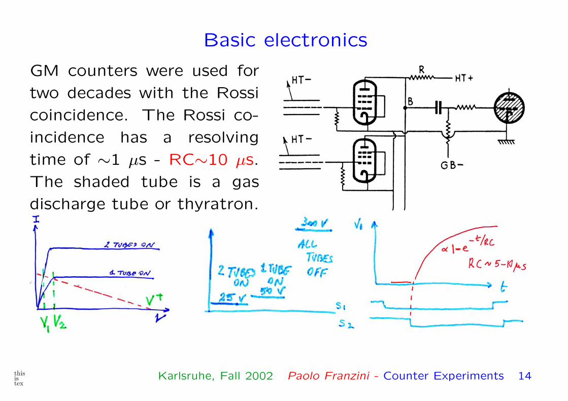
Basic electronics
GM counters were used for
two decades with the Rossi
coincidence. The Rossi co-
incidence has a resolving
time of ∼1 µs - RC∼10 µs.
The shaded tube is a gas
discharge tube or thyratron.
thisistex
Karlsruhe, Fall 2002 Paolo Franzini - Counter Experiments 14
At accelerators the GM counter has been replaced by scintillator
and photomultipliers. Typical fast scintillator has the following
characteristics: 1. Bulk material plastic, density ∼1 gr/cm3;
light output ≤10,000 blue photons per MeV of energy loss, rise
and fall time around 1 ns.
10,000 photons are a large number. Only a few % can be
guided to a photocathode where the photons extract electrons,
photoelectric effect, efficiency <30%.
It is easy to obtain a signal of 100 p-e’s from a min. ion. par-
ticle crossing a 2 mm thick plastic scintillator viewed through
a long light guide. Since a photomultiplier is a noise-less am-
plifier (kT � hω), it is “easy” to have efficient counters with
time resolution �1 ns, 50 ps being possible.
thisistex
Karlsruhe, Fall 2002 Paolo Franzini - Counter Experiments 15

scint
PM
photocathode
photon
dyN
dy1
dy2
A
2N
e
LG
output
particle
Photocathode and elec-
tron multiplier are en-
closed in a glass envelope,
under high vacuum.
The counter at left is
typical of 1950-80 and
even today is seen in test
beams.
Plastic scintillator can be
machined or molded to
any shape.
thisistex
Karlsruhe, Fall 2002 Paolo Franzini - Counter Experiments 16
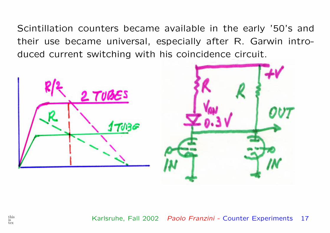
Scintillation counters became available in the early ’50’s and
their use became universal, especially after R. Garwin intro-
duced current switching with his coincidence circuit.
thisistex
Karlsruhe, Fall 2002 Paolo Franzini - Counter Experiments 17
There is another important difference between the GM counter
and fast scintillation counters.
The first produces a large signal through a saturated gain
mechanism, the signal amplitude is constant. Both scintilla-
tion and the photomultiplier tube (PM, photube) are linear
and the final signal is proportional to the initial energy loss in
the scintillator.
This is in general more information, but it is often necessary
to accept only signals larger than a threshold, or signals in an
interval: Smin < S < Smax.
By the end of the ’50’s solid state devices are fully available.
Ultimately they did change experimental particle physics.
thisistex
Karlsruhe, Fall 2002 Paolo Franzini - Counter Experiments 18
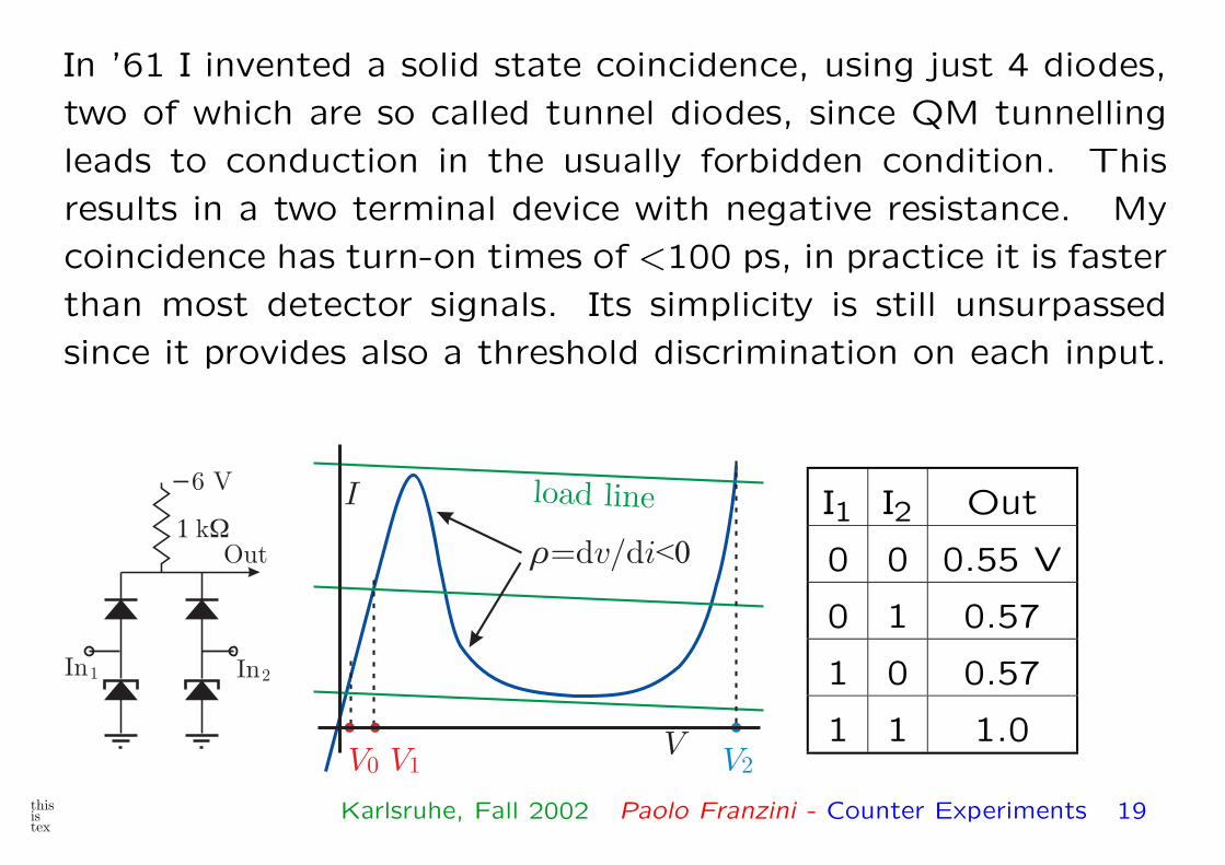
In ’61 I invented a solid state coincidence, using just 4 diodes,
two of which are so called tunnel diodes, since QM tunnelling
leads to conduction in the usually forbidden condition. This
results in a two terminal device with negative resistance. My
coincidence has turn-on times of <100 ps, in practice it is faster
than most detector signals. Its simplicity is still unsurpassed
since it provides also a threshold discrimination on each input.
In2
Out� �k
In1
�6 VI
V V0 1 V2V
�=d /dv i<0
load line I1 I2 Out
0 0 0.55 V
0 1 0.57
1 0 0.57
1 1 1.0
thisistex
Karlsruhe, Fall 2002 Paolo Franzini - Counter Experiments 19
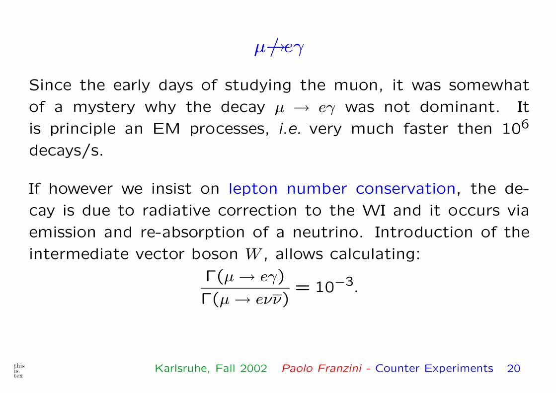
µ→/ eγ
Since the early days of studying the muon, it was somewhat
of a mystery why the decay µ → eγ was not dominant. It
is principle an EM processes, i.e. very much faster then 106
decays/s.
If however we insist on lepton number conservation, the de-
cay is due to radiative correction to the WI and it occurs via
emission and re-absorption of a neutrino. Introduction of the
intermediate vector boson W , allows calculating:
Γ(µ → eγ)
Γ(µ → eνν)= 10−3.
thisistex
Karlsruhe, Fall 2002 Paolo Franzini - Counter Experiments 20
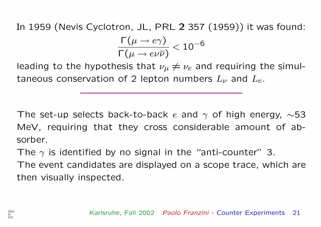
In 1959 (Nevis Cyclotron, JL, PRL 2 357 (1959)) it was found:
Γ(µ → eγ)
Γ(µ → eνν)< 10−6
leading to the hypothesis that νµ �= νe and requiring the simul-
taneous conservation of 2 lepton numbers Lν and Le.
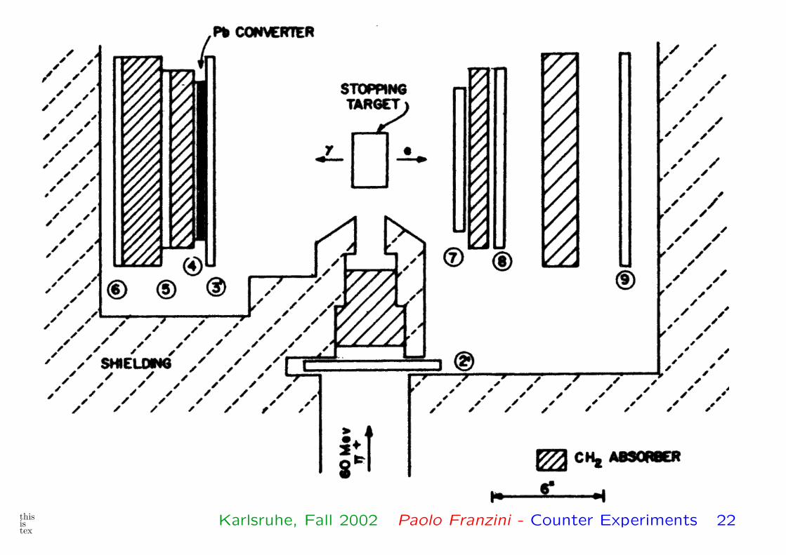
The set-up selects back-to-back e and γ of high energy, ∼53
MeV, requiring that they cross considerable amount of ab-
sorber.
The γ is identified by no signal in the “anti-counter” 3.
The event candidates are displayed on a scope trace, which are
then visually inspected.
thisistex
Karlsruhe, Fall 2002 Paolo Franzini - Counter Experiments 21
thisistex
Karlsruhe, Fall 2002 Paolo Franzini - Counter Experiments 22
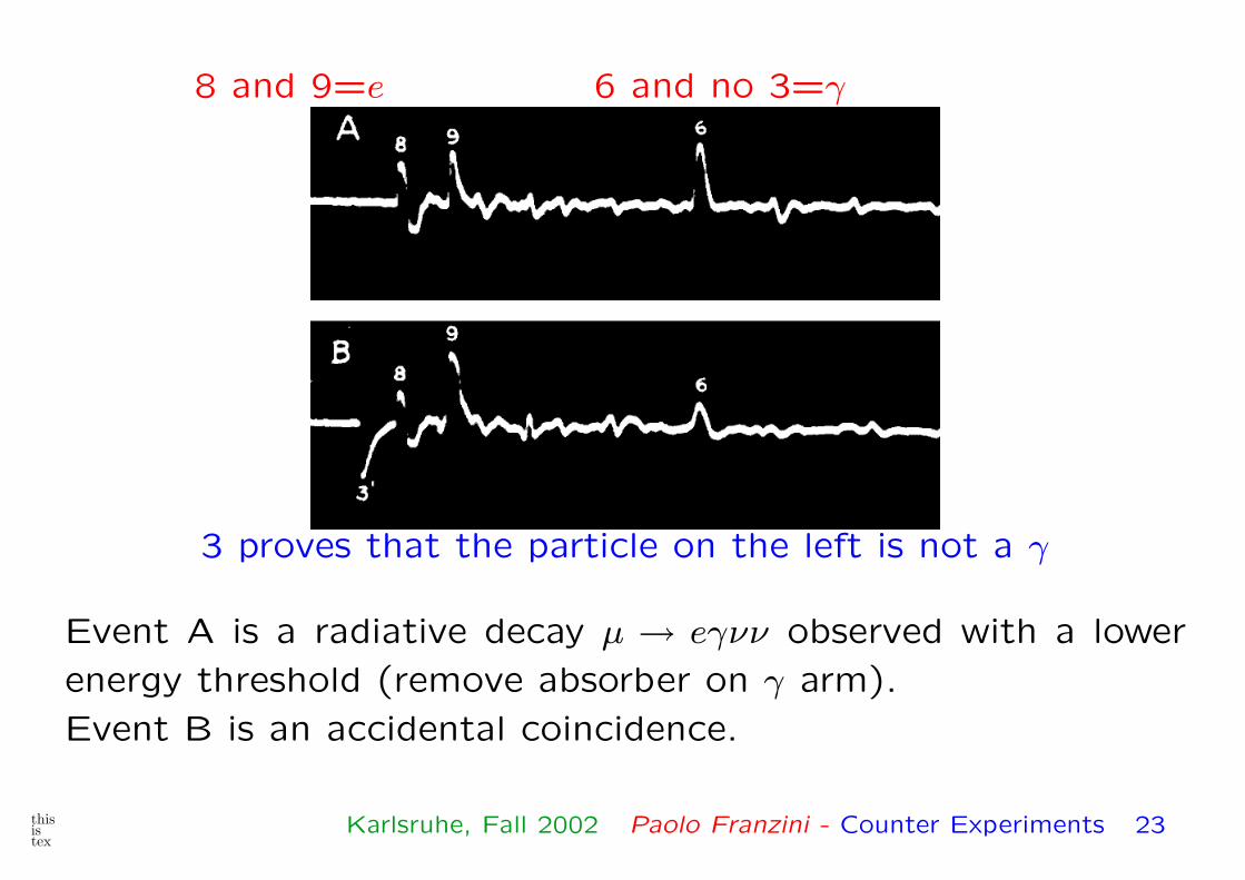
8 and 9=e 6 and no 3=γ
3 proves that the particle on the left is not a γ
Event A is a radiative decay µ → eγνν observed with a lower
energy threshold (remove absorber on γ arm).
Event B is an accidental coincidence.
thisistex
Karlsruhe, Fall 2002 Paolo Franzini - Counter Experiments 23
The muon neutrino helicity
Soon after the discovery of parity violation a large electron
polarization 〈�σ · pe〉 ∼ −1(β) was observed, also proving P\. The
negative helicity of the electron could be due to a eγµ(1− γ5)ν
or a e(1 + γ5)ν coupling (V,A or S,T). The observed helicity
of the neutrino in β-decay, −1, together with other results,
confirms the V −A interaction of Feynman and Gell-Mann and
of Marshak and Sudarshan.
The emerging evidence that there is an independent conserva-
tion of electrons and muons and their associated neutrino, or
just that νe �= νµ begs for a measurement of the νµ helicity.
Of course one does not measure the neutrino polarization –
but, by angular momentum conservation, the neutrino helicity
thisistex
Karlsruhe, Fall 2002 Paolo Franzini - Counter Experiments 24
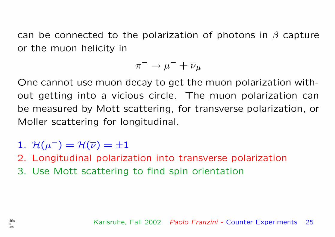
can be connected to the polarization of photons in β capture
or the muon helicity in
π− → µ− + νµ
One cannot use muon decay to get the muon polarization with-
out getting into a vicious circle. The muon polarization can
be measured by Mott scattering, for transverse polarization, or
Moller scattering for longitudinal.
1. H(µ−) = H(ν) = ±1
2. Longitudinal polarization into transverse polarization
3. Use Mott scattering to find spin orientation
thisistex
Karlsruhe, Fall 2002 Paolo Franzini - Counter Experiments 25
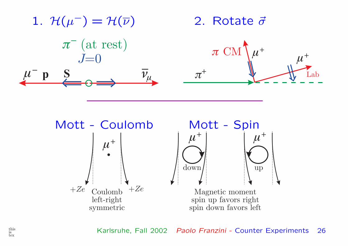
1. H(µ−) = H(ν) 2. Rotate �σ
����
�� (at rest)J=0
p S ���� CM
Lab��
��
Mott - Coulomb Mott - Spin
+Ze +Ze
��
Coulombleft-right
symmetric
����
updown
Magnetic momentspin up favors rightspin down favors left
thisistex
Karlsruhe, Fall 2002 Paolo Franzini - Counter Experiments 26

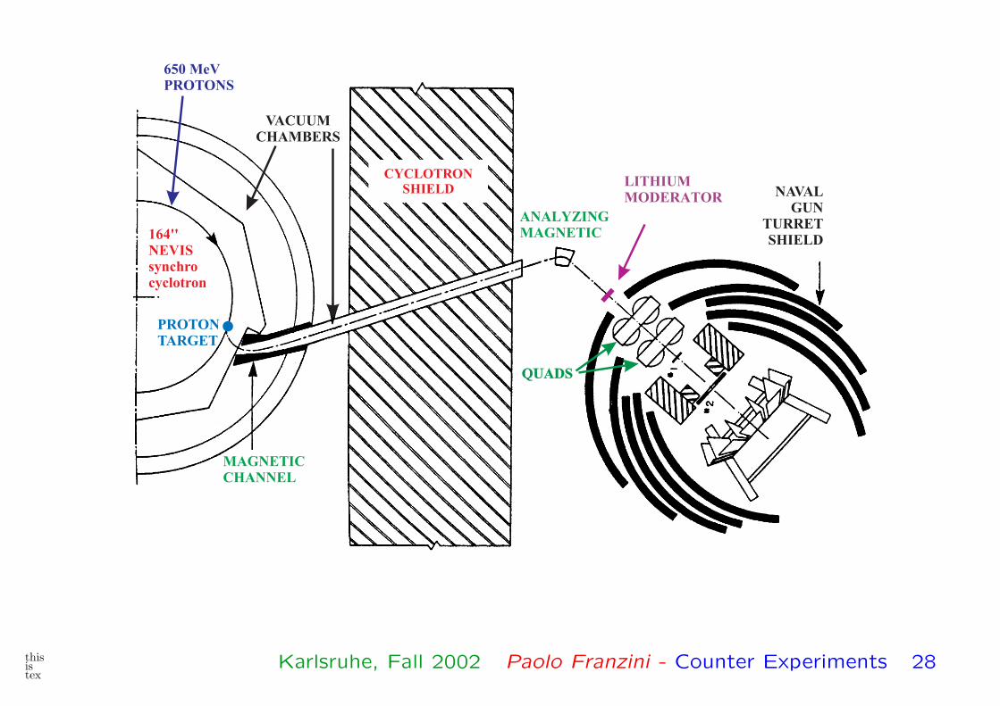
The basic arrangement
Measure left-right asymmetry of back-scattered negative muons.
Gives maximum asymmmetry.
�
�
L
RC+Pb
Tπ=43 MeV
thisistex
Karlsruhe, Fall 2002 Paolo Franzini - Counter Experiments 27
thisistex
Karlsruhe, Fall 2002 Paolo Franzini - Counter Experiments 28
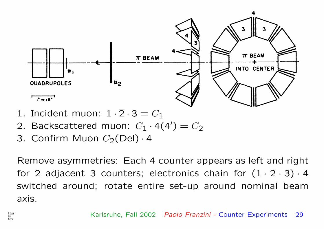
1. Incident muon: 1 · 2 · 3 = C1
2. Backscattered muon: C1 · 4(4′) = C2
3. Confirm Muon C2(Del) · 4
Remove asymmetries: Each 4 counter appears as left and right
for 2 adjacent 3 counters; electronics chain for (1 · 2 · 3) · 4switched around; rotate entire set-up around nominal beam
axis.
thisistex
Karlsruhe, Fall 2002 Paolo Franzini - Counter Experiments 29
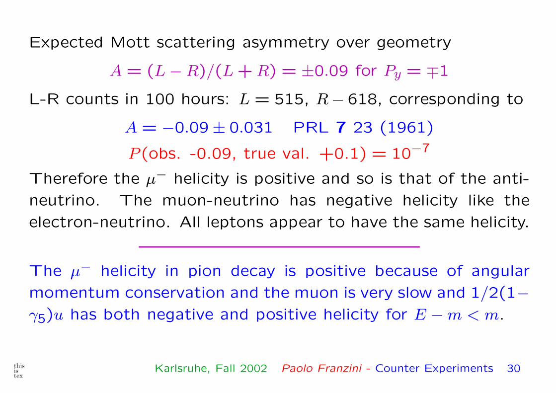
Expected Mott scattering asymmetry over geometry
A = (L − R)/(L + R) = ±0.09 for Py = ∓1
L-R counts in 100 hours: L = 515, R− 618, corresponding to
A = −0.09 ± 0.031 PRL 7 23 (1961)
P (obs. -0.09, true val. +0.1) = 10−7
Therefore the µ− helicity is positive and so is that of the anti-
neutrino. The muon-neutrino has negative helicity like the
electron-neutrino. All leptons appear to have the same helicity.
The µ− helicity in pion decay is positive because of angular
momentum conservation and the muon is very slow and 1/2(1−γ5)u has both negative and positive helicity for E − m < m.
thisistex
Karlsruhe, Fall 2002 Paolo Franzini - Counter Experiments 30
µ→/ eγ - Again, 20 years later
The absence of mixing of (νe e−) with (νµ µ−) compared
to (u d) and (c s) is guaranteed if the neutrino have
zero mass. This is not so, but the limits on the neutrino
masses ensure that µ → eγ remains unmeasurably small.
There are however other mechanisms and I refer you to
Marciano’s lectures.
Historically, the upper limit for Γ(µ → eγ)/Γ(µ → eνν)
was lowered to 2.2 × 10⁻⁸ in 1964 at the Chicago Cy-
clotron.
In the late 70’s, rumors spread out to the effect that the
decay was observed. This led to a spate of predictions,
mostly (15 of them) in ’77, in the range 10−8 to 10−26.
thisistex
Karlsruhe, Fall 2002 Paolo Franzini - Counter Experiments 31
Most of them could be abandoned today. Supersymmetry
was not yet in fashion.
Anyway, in 1978 we set up an experiment at the old venera-
ble, partly renewed Nevis Cyclotron aiming to reach 10−10.
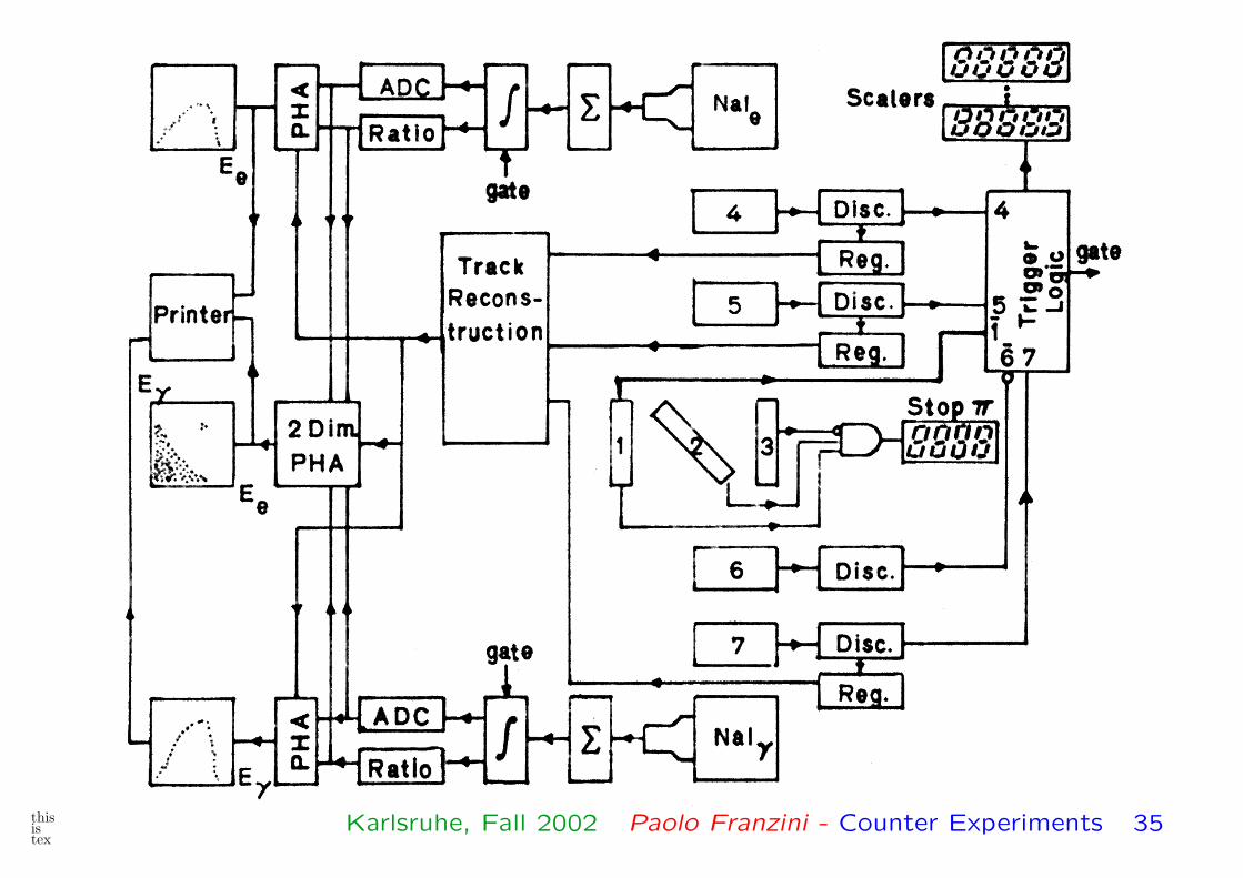
The experiment is an example of very extensive use of
electronics in order to extract digital information from the
apparatus in the form of final physical results.
The entire analysis was done by hardware, in real time as
compared to past, present and future experiments which,
beginning about that time, extract and store data for off-
line analysis.
thisistex
Karlsruhe, Fall 2002 Paolo Franzini - Counter Experiments 32
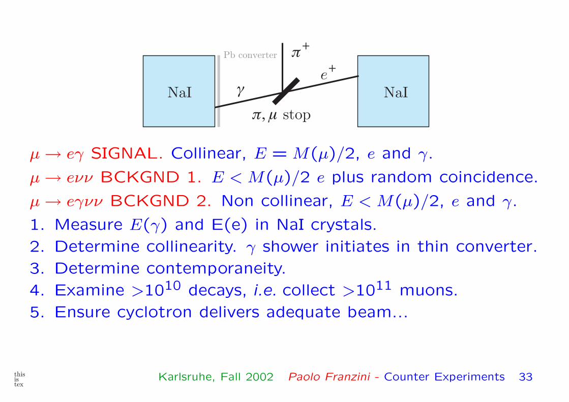
NaINaI
��
e�
���� stop
Pb converter
µ → eγ SIGNAL. Collinear, E = M(µ)/2, e and γ.
µ → eνν BCKGND 1. E < M(µ)/2 e plus random coincidence.
µ → eγνν BCKGND 2. Non collinear, E < M(µ)/2, e and γ.
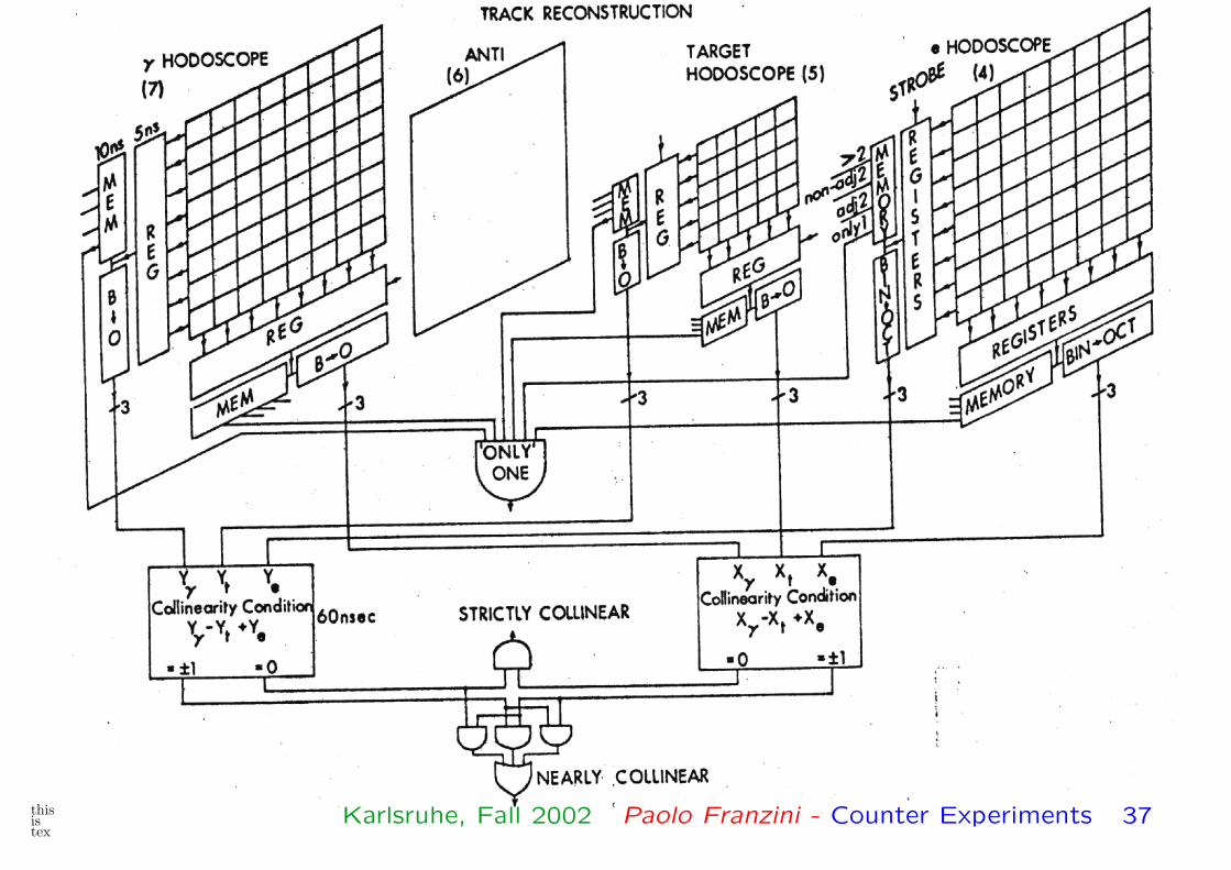
1. Measure E(γ) and E(e) in NaI crystals.
2. Determine collinearity. γ shower initiates in thin converter.
3. Determine contemporaneity.
4. Examine >1010 decays, i.e. collect >1011 muons.
5. Ensure cyclotron delivers adequate beam...
thisistex
Karlsruhe, Fall 2002 Paolo Franzini - Counter Experiments 33
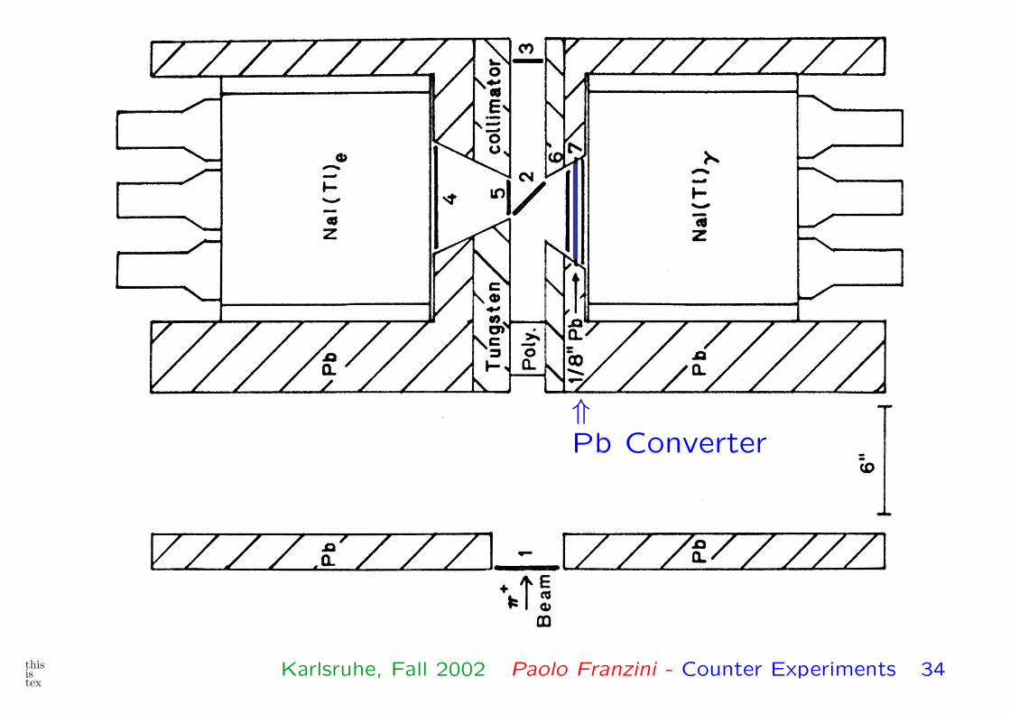
⇑Pb Converter
thisistex
Karlsruhe, Fall 2002 Paolo Franzini - Counter Experiments 34
thisistex
Karlsruhe, Fall 2002 Paolo Franzini - Counter Experiments 35

TRIGGER
thisistex
Karlsruhe, Fall 2002 Paolo Franzini - Counter Experiments 36
thisistex
Karlsruhe, Fall 2002 Paolo Franzini - Counter Experiments 37

Producing histograms
thisistex
Karlsruhe, Fall 2002 Paolo Franzini - Counter Experiments 38

A 100 kW HIFI amplifier
Those were the last
days that physicists
still worked on machine
and experiment.
To improve, by almost
1000-fold, the duty
cycle we built a super
HIFI amp, water
cooled no less.
thisistex
Karlsruhe, Fall 2002 Paolo Franzini - Counter Experiments 39

No µ → eγ found
We got to a limit of
<2×10⁻⁹ without find-
ing a single candidate
for µ → eγ decay.
We could have eas-
ily reached the goal of
10−10.
The Nevis cyclotron
was however retired af-
ter 30 years of honor-
able service.
thisistex
Karlsruhe, Fall 2002 Paolo Franzini - Counter Experiments 40
Today it is hard to “see” a coincidence in an experiment.
Modern trigger systems, for instance, consist of manipula-
tions of large amounts of information through vast logic arrays,
equivalent to hundreds or tens of thousand coincidences.
We then measure time intervals between signals, with digital
output, i.e. as numbers.
Computers, running a complicated set of program, further ma-
nipulate the event information. Or, more likely, builds up dis-
tributions which are then again manipulated to obtain a (hope-
fully) relevant result.
That’s the way today, still coincidence were used for well over
fifty years. The concept remains valid today.
thisistex
Karlsruhe, Fall 2002 Paolo Franzini - Counter Experiments 41