COST EFFECTIVE FILTRATION OF STEEL CASTINGS · PDF file1 COST EFFECTIVE FILTRATION OF STEEL...
22
1 COST EFFECTIVE FILTRATION OF STEEL CASTINGS David HRABINA Vesuvius Slavia a.s., Trinec (Czech Republic) ABSTRACT Foundries face a constant challenge to produce high quality castings to satisfy their customer requirements and expectations. Those that can produce high quality castings with minimal or no welds, cost effectively, and with short lead time, win the contracts. Ceramic Foam Filtration is a recognised technology for reducing casting upgrading by removing non-metallic inclusions and oxide films from the metal stream as the mould fills. The ability of the filters to remove the energy that causes turbulence, and introduce laminar flow to the metal stream, is also considered a major benefit resulting in improved casting homogeneity and surface finish. Keywords: Steel Casting, Metal Stream, Filtration, Ceramic Foam, remove Inclusions Selection of an optimal filtration method for the casting according to casting weight, cast material, filtration requirements and casting geometry is the key to success. A number of alternative filter application methods can be used, these include: Conventional filter application in specifically designed filter prints Direct pour KALPUR offers filter applications with the added benefit of improved casting yield. Optimal thermal gradient extends the feeding distances, and eliminates the running system, providing the opportunity to use smaller moulding box. TURBOPRINT is a new technology based on swirling the metal at the filter inlet face. This has the effect of assisting the priming of the filter by heating the filter before the metal has to pass through it, which is especially important for steel grades sensitive to freezing on the filter surface. HOLLOTEX FSt provides an opportunity to easily implement filters into ceramic tiles as part of running system located under the casting particularly designed for medium weight castings. HOLLOTEX CFU is an efficient ceramic centrifugal filtration unit developed for heavy castings. A high metal flow rate is achieved through the filter system ensuring the required fill time for the casting is not compromised. The use of several CFU units in a mould allows practically unlimited filtration capacity.
Transcript of COST EFFECTIVE FILTRATION OF STEEL CASTINGS · PDF file1 COST EFFECTIVE FILTRATION OF STEEL...
1
COST EFFECTIVE FILTRATION OF STEEL CASTINGS
David HRABINA
Vesuvius Slavia a.s., Trinec (Czech Republic)
ABSTRACT
Foundries face a constant challenge to produce high quality castings to satisfy their
customer requirements and expectations. Those that can produce high quality castings with
minimal or no welds, cost effectively, and with short lead time, win the contracts.
Ceramic Foam Filtration is a recognised technology for reducing casting upgrading by
removing non-metallic inclusions and oxide films from the metal stream as the mould fills.
The ability of the filters to remove the energy that causes turbulence, and introduce laminar
flow to the metal stream, is also considered a major benefit resulting in improved casting
homogeneity and surface finish.
Keywords: Steel Casting, Metal Stream, Filtration, Ceramic Foam, remove Inclusions
Selection of an optimal filtration method for the casting according to casting weight, cast
material, filtration requirements and casting geometry is the key to success. A number of
alternative filter application methods can be used, these include:
Conventional filter application in specifically designed filter prints
Direct pour KALPUR offers filter applications with the added benefit of improved
casting yield. Optimal thermal gradient extends the feeding distances, and eliminates
the running system, providing the opportunity to use smaller moulding box.
TURBOPRINT is a new technology based on swirling the metal at the filter inlet face.
This has the effect of assisting the priming of the filter by heating the filter before the
metal has to pass through it, which is especially important for steel grades sensitive to
freezing on the filter surface.
HOLLOTEX FSt provides an opportunity to easily implement filters into ceramic tiles
as part of running system located under the casting particularly designed for medium
weight castings.
HOLLOTEX CFU is an efficient ceramic centrifugal filtration unit developed for heavy
castings. A high metal flow rate is achieved through the filter system ensuring the
required fill time for the casting is not compromised. The use of several CFU units in a
mould allows practically unlimited filtration capacity.

2
There is no single filtration technique suitable for application to castings of all weighs and
metal grades. This paper focuses on the key benefits, and limiting factors, of the various
application techniques available.
1. INTRODUCTION
The filtration of molten steel traps non-metallic inclusions and reduces turbulence during
mould filling. Foam filters are particularly efficient at consuming dynamic energy and
converting turbulent mould filling to laminar mould filling through frictional forces. This
reduces mould erosion, improves the casting surface, and minimizes subsequent re-
oxidation. In addition capture of non-metallic inclusions increases metal cleanliness and
improves mechanical properties such as: fatigue, notch toughness, and elongation
properties. Foam filtration is globally recognized as an efficient tool to improve castings
quality and reduce supply time and production cost.
2. STEEL VERSUS IRON
Why filtration of iron castings is already commonly used whilst so many steel foundries are
still reluctant to filter?
There are many reasons that might be sorted into two main categories.
Evidence of steel filtration profitability
Technical issues with to filtering steel castings
3. EVIDENCE OF STEEL FILTRATION PROFITABILITY
Is not so visible like for iron. Steel filters are much more expensive than filters for iron and
defective iron castings are usually scrapped while steel castings are welded.
Often times foundries primarily focus on purchasing costs and attempt to avoid the need of
use for filters rather than focusing on an overall operational cost reduction- leading to
optimized operational profitability. Foundries that have an understanding of their overall
welding costs typically do not lack evidence of profitability improvements with use of steel
filtration technologies. For example, welding labour costs associated with casting upgrade -
which can vary from 150 to 200 USD / hour - is typically a direct variable that can be
associated with the value that steel filtration offers. Other additional foundry costs
including: overheads for crane manipulation, inspection and repeat inspection, additional
heat treatment, shot blasting, additional machining, throughput, etc. are other variables of
added-value that are often overlooked.
4. TECHNICAL ISSUES WITH FILTERING TO STEEL CASTINGS
Is much more challenging than filtration of iron for reasons following, but not limited to:
Fluidity of molten steel is much lower due to lower carbon levels

3
Higher melting temperatures
Higher gas solubility/affinity
Narrow solidification interval and higher heat thermal conductivity having a
tendency to freeze on the filter facial surface.
The methoding and metallurgical staff at the foundry must be well experienced and
knowledgeable to implement steel filtration successfully to achieve targeted benefits.
5. IMPORTANCE OF FILTERED RUNNING SYSTEMS DESIGN AND
METALLURGY
Critically important to producing high quality steel castings - cost effectively - is close
cooperation of foundry methoding and metallurgical departments. It is not possible to filter
metal that is damaged by unacceptable metallurgical process. Conversely, excellent
metallurgy cannot independently overcome application mistakes.
For example, final alloying in the ladle will always have a negative impact on filtration of
molten steel. Similarly, such practice will likely cause a quality problem even for
unfiltered castings. Oxides such as MnO, SiO2 and Cr2O3 cause internal friction and tend to
reduce steel fluidity, which promotes filters prematurely clogging with slag [Figure 1].
Well prepared filtered metal exposed to a pressurized running system will cause a fountain
effect as the metal enters the mould. This likely leads to mould erosion, metal splashing,
and re-oxidation leading to casting surface defects [Figure 2].
Melting, alloying, de-oxidation, and metal transfer of steel is extremely important to casting
quality. Due to the complex nature of the process – it is not possible for all details to be
covered in this paper. More details related to metallurgy and its impact on filtration
performance is addressed in supplemental presentations.

4
Figure 1: Ellingham diagram
Figure 2: Fountain effect of pressurized running system

5
6. THE BEST FILTRATION METHOD
Various filtration application techniques are available today. Every option provides a trade-
off and is more or less suitable for certain casting groups and metal grades. There is no
single filtration method suitable for all steel castings. Achieving success with selection of
an optimal filtration method is subject to the following key factors:
Melting process
De-oxidation practice
Chemical composition of cast metal
Moulding material
Pouring temperature
Fill time
Castings geometry
Quality requirements
Total cast weight
7. CONVENTIONAL IN-LINE FILTRATION
By foam filters located in vertical [Figure 3] and/or horizontal [Figure 4] filter prints are
still the most common type of filtration. This method was initially developed for filtration
of iron in the 1980’s and was first adopted by steel foundries implementing filtration
according to the iron foundry experiences and knowledge.
Figure 3: Vertical Print

6
Figure 4: Horizontal Print
Positive effects from steel filtration, such as improvements to casting surface, was clearly
visible and encouraged foundries to utilize filtration of steel castings more regularly.
Although fettling/welding cost reduction has been found to be very positive - some
disadvantages discouraged expansion to filter more steel castings.
Figure 5: Bolster for Railway from low alloy steel

7
Figure 6: Flap from stainless steel
Both vertical [Figure 5] and horizontal [Figure 6] prints are used for green sand as well as
for chemically bonded sand. This method is relatively inexpensive and easy to adopt
because the filters are inserted into the mould from the parting line just before mould
assembly. Cast weight is typically ranges from 20 kg up to 500 kg, but might be also
exceptionally heavier. Vertical prints are more efficient when located in close proximity to
the downsprue. Horizontal prints often suffer from metal by-pass [Figure 7] and there is a
filter clogging risk when metal leaks from the ladle nozzle onto the filter surface located
directly under the downsprue [Figure 8] which can be a problem for steel foundries.
Figure 7: Drowned filter under the parting line – By pass present

8
Figure 8: Filter is clogged by leaking metal from the nozzle
Both vertical and horizontal prints introduce a risk for metal freezing along with an
extension of pouring time. This typically occurs when filters are located further distance
from the downsprue and cast metal is carbon or low alloy steel with a short freezing range.
Foundries typically increase pouring temperature compared to unfiltered production to
overcome this problem. The pouring time is influenced by heat distribution in the ladle
[Figure 9] and by low initial nozzle temperature. For bottom pour ladles, a smaller nozzle
diameter accelerates the cooling effect on the metal. Cast metal cools down also within the
running system and partially freeze partially on the filter surface and blocking it. Such part
of the filter might not be re-melted again and does not allow metal to pass through it. This
might lead to filtration capacity reduction and extension in filling time or even result in a
blocked filter (or ‘short pour’) [Figure 10].
Figure 9: Cold metal at the bottom comes out firstly

9
Figure 10: Frozen metal blocks the filter
8. DIRECT POUR – KALPUR
is likely the easiest filtration method to implement. Pattern modifications are often not
required and can this filtration technique can be tried very quickly. Direct pour is less
sensitive to short pours compared to in-line filtration, however small castings with minimal
KALPUR volume suffer from the cold nozzle effect - especially with low carbon alloy steel
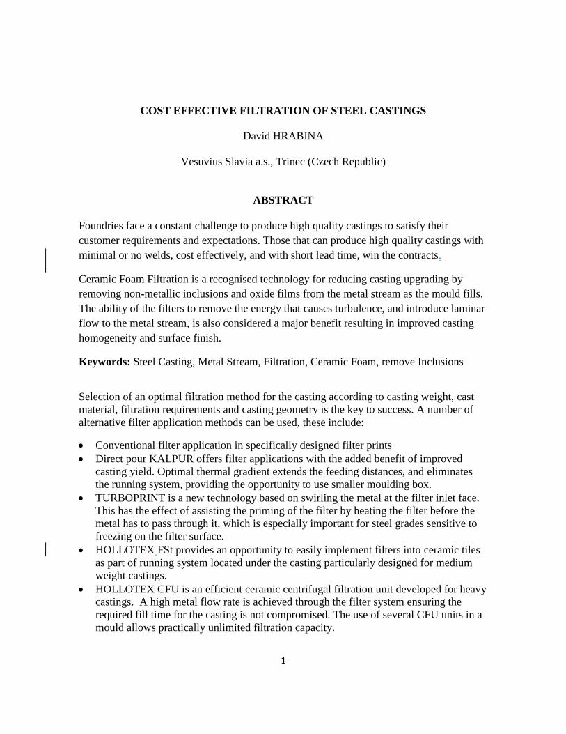
[Figure 11]. Excellent metallurgy and de-oxidation practice complimented by argon
purging through a porous plug at the bottom of the ladle that is lined with a highly
insulating lining [Figure 12] reduces this risk of short pours significantly. However, there is
no guarantee that the risk is completely eliminated – especially for the first castings poured
from the ladle when the nozzle is relatively cold.
Figure 11: Short pour with Zr filter Ø50mm
10
Figure 12: Ladle with argon purging plug
In addition to casting surface improvements, KALPUR offers additional overall operational
improvements. There are two primary advantages over other filtration techniques.
Running system elimination – yield enhancement
Temperature distribution optimisation
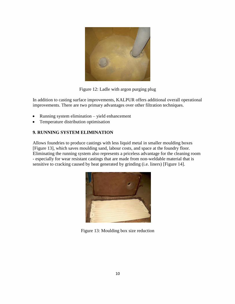
9. RUNNING SYSTEM ELIMINATION
Allows foundries to produce castings with less liquid metal in smaller moulding boxes
[Figure 13], which saves moulding sand, labour costs, and space at the foundry floor.
Eliminating the running system also represents a priceless advantage for the cleaning room
- especially for wear resistant castings that are made from non-weldable material that is
sensitive to cracking caused by heat generated by grinding (i.e. liners) [Figure 14].
Figure 13: Moulding box size reduction

11
Figure 14: Runner fettling elimination
10. TEMPERATURE DISTRIBUTION OPTIMISATION
Allows the hottest metal to be located inside the riser, which in turn reduces the thermal
gradient and increases the distance from this riser. This extends feeding distances and
allows reduction in the number of sleeves required [Figure 15] versus gating with a
conventional running system, [Figure 16] which distributes hot metal into the casting and
the cold metal fills the sleeve cavities.
Figure 15: Direct pour by single sleeve
Figure 16: Convention runner with 2 sleeves
Special attention must be paid to ensure that filters are properly covered by molten metal.
Particularly, lip pour ladles might not provide sufficient metal flow rate to fill up the
KALPUR unit completely and as a consequence air can become entrapped. This can
reduce filtration efficiency and cause gas bubbles on the casting surface. When using a
direct pour technique, it becomes extremely critical to have a metal flow that aligns and

12
exceeds the filter capacity when carbon bonded filters are used. Zirconia filters are more
oxidation resistance, but filtration efficiency is reduced if sufficient metal flow rate is not
applied. Direct pour is more suitable for higher carbon content steel, which is less sensitive
to gas pick up when metal falls into the mould cavity after the filter.
Distance from ladle nozzle to filter surface needs to be considered carefully as well. This
depends on metal head in the ladle, nozzle diameter, cast metal grade, pouring temperature,
and importantly on experience of the ladle operator. Every effort should be made to
minimize the ladle spout distance above the filter so that risk for filter breakage is
mitigated. Practical experience is needed to design an optimal solution.
11. TURBOPRINT
is a new patented innovative technology based on metal swirling at the filter inlet face. It
has been developed to overcome existing deficiency of in-line and direct pour methods.
The TURBOPRINT concept has promoted success with filtration to foundries who have
failed in the past.
The TURBOPRINT concept uses initial cold and polluted metal from the ladle to wash the
filter surface and heat it up. This first metal is washed away by incoming clean and hot
metal, which enacts inward centrifugal forces to disperse the slag/containments from the
filter surface to the centre of spinning chamber [Figure 17]. Slag and non-metallic low
density inclusions are centrifuged into the low velocity swirling centre [Figure 18] and the
filter surface is kept clean by fresh metal. This principle eliminates short pour risk and
increases filtration capacity and efficiency at the same time. This filtration technology also
eliminates filter breakage risk by metal impact because the initial metal impacts the filter
surface tangentially and not directly.
Figure 17: Metal swirling at inlet face of filters

13
Figure 18: Swirl inclusions entrapment
With high quality metallurgy TURBOPRINT allows for similar mould filling time as
unfiltered castings poured at the same. The swirling effect is more efficient with a higher
metal flow rate since high metal velocity increases the centrifuge effects on slag and
inclusion removal. There is more benefit when bottom pour ladles are used in conjunction
due to a higher dynamic energy of metal spinning. This deficiency might be mitigated by
pouring cup extension over the mould.
To achieve maximum filtration benefits it is important to fill the mould from the bottom to
minimize any turbulence and metal splashing leading to secondary re-oxidation. In [Figure
19], TURBOPRINT is located under the core of the valve casting so that it fills from the
bottom rather than from the parting line. Cope mark of the TURBOPRINT is in the core,
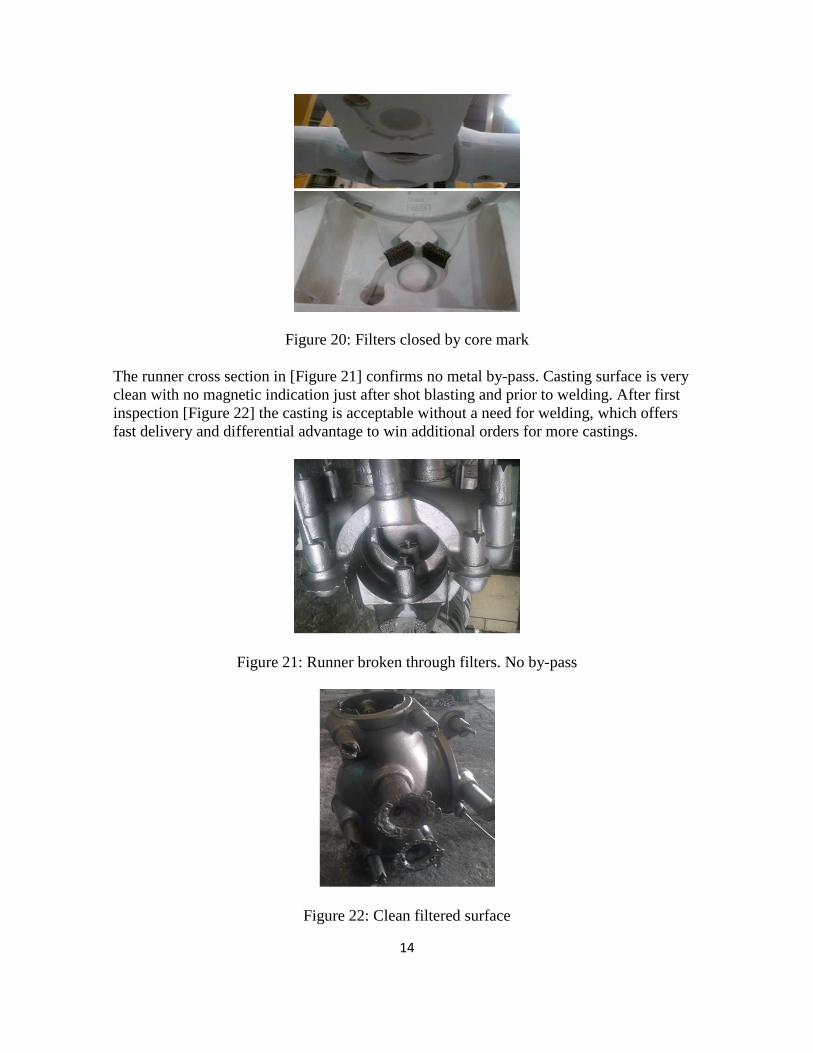
which closes filters inside to avoid any metal by-pass over the filters [Figure 20].
Figure 19: Horizontal TURBOPRINT under the core
14
Figure 20: Filters closed by core mark
The runner cross section in [Figure 21] confirms no metal by-pass. Casting surface is very
clean with no magnetic indication just after shot blasting and prior to welding. After first
inspection [Figure 22] the casting is acceptable without a need for welding, which offers
fast delivery and differential advantage to win additional orders for more castings.
Figure 21: Runner broken through filters. No by-pass
Figure 22: Clean filtered surface

15
The butterfly valve [Figure 23] is made from high alloy CF8M steel has a high sensitivity
to filter freezing. Therefore, to reduce the risk of the filter freezing and causing a short
pour – the casting is filtered with a vertical TURBOPRINT located partially under the core
with the top half inside the core. This vertical TURBOPRINT provides higher filtration
capacity and flow rate compare to a horizontal TURBOPRINT design. The quality
inspection for this casting [Figure 24] requires a dye penetration test. Implementation of
the vertical TURBOPRINT reduced welding costs by approximately 50% compared to an
unfiltered casting design. TURBOPRINT is used for cast weights from 50 kg to 1500kg.
Figure 23: Vertical TURBOPRINT
Figure 24: No ceramic part of running system
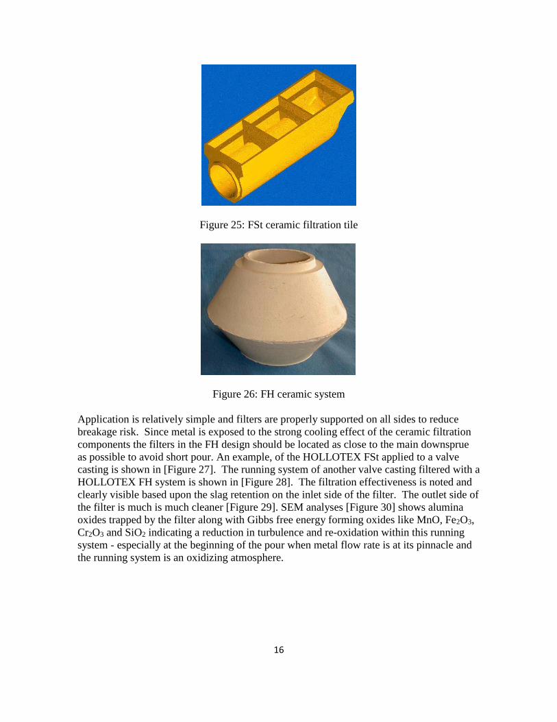
12. HOLLOTEX FST AND FH
Is a filtration technology where filters are used in ceramic running systems [Figure 25 &
Figure 26] typically under the casting, which allows access to connect in-gates to an
optimal part of the casting to achieve laminar filling without metal splashing, mould
erosion, and secondary re-oxidation. This technique is typically used for heavier castings
that exceed the capabilities of in-line, direct pour, and TURBOPRINT.
16
Figure 25: FSt ceramic filtration tile
Figure 26: FH ceramic system
Application is relatively simple and filters are properly supported on all sides to reduce
breakage risk. Since metal is exposed to the strong cooling effect of the ceramic filtration
components the filters in the FH design should be located as close to the main downsprue
as possible to avoid short pour. An example, of the HOLLOTEX FSt applied to a valve
casting is shown in [Figure 27]. The running system of another valve casting filtered with a
HOLLOTEX FH system is shown in [Figure 28]. The filtration effectiveness is noted and
clearly visible based upon the slag retention on the inlet side of the filter. The outlet side of
the filter is much is much cleaner [Figure 29]. SEM analyses [Figure 30] shows alumina
oxides trapped by the filter along with Gibbs free energy forming oxides like MnO, Fe2O3,
Cr2O3 and SiO2 indicating a reduction in turbulence and re-oxidation within this running
system - especially at the beginning of the pour when metal flow rate is at its pinnacle and
the running system is an oxidizing atmosphere.

17
Figure 27: FSt filtration of Valve
Figure 28: FH Ceramic system
Figure 29: Effective slag retention by filters

18
Figure 30: Detailed SEM inclusions analyses
13. HOLLOTEX CFU
is a new patent protected filtration technology especially developed for filtration of the
heaviest and most complicated castings that demand a high metal flow rate and critical
level of quality requirements without compromising filling time or pouring temperature
modification. This filtration system is based upon the principal of metal spinning around
the filters and heating them up before passing through. This filtration unit [Figure 31]
accommodates the first cold and dirty metal and centrifuges it away from the filters’ surface
in a similar fashion as TURBOPRINT. The swirling action of the metal reduces the risk of
direct impact on the filter surface [Figure 32] and overcomes the challenge of filters failing,
which has been observed with other swirling filtration devices. The swirling action also
promotes the low density slag and inclusions to float, which keeps the filter surface clean.
The HOLLOTEX CFU design allows for an equal amount of metal to pass through each
filter resulting in an optimal filtration capacity.
Figure 31: HOLLOTEX CFU
19
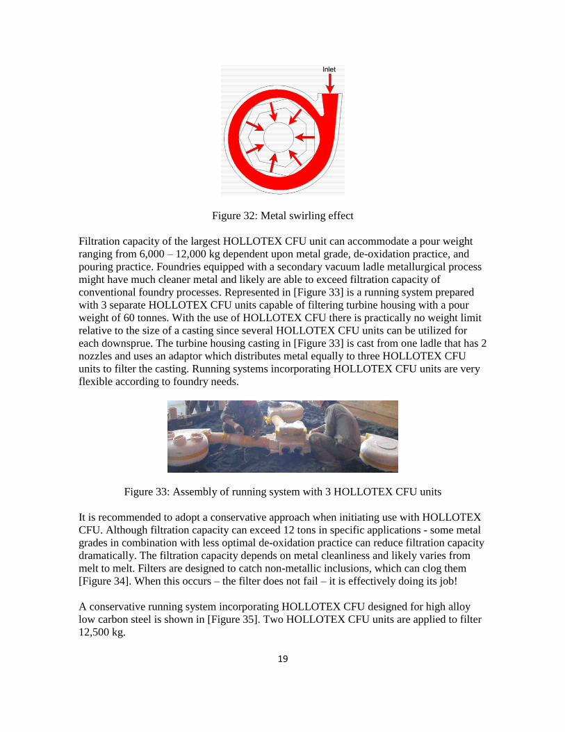
Figure 32: Metal swirling effect
Filtration capacity of the largest HOLLOTEX CFU unit can accommodate a pour weight
ranging from 6,000 – 12,000 kg dependent upon metal grade, de-oxidation practice, and
pouring practice. Foundries equipped with a secondary vacuum ladle metallurgical process
might have much cleaner metal and likely are able to exceed filtration capacity of
conventional foundry processes. Represented in [Figure 33] is a running system prepared
with 3 separate HOLLOTEX CFU units capable of filtering turbine housing with a pour
weight of 60 tonnes. With the use of HOLLOTEX CFU there is practically no weight limit
relative to the size of a casting since several HOLLOTEX CFU units can be utilized for
each downsprue. The turbine housing casting in [Figure 33] is cast from one ladle that has 2
nozzles and uses an adaptor which distributes metal equally to three HOLLOTEX CFU
units to filter the casting. Running systems incorporating HOLLOTEX CFU units are very
flexible according to foundry needs.
Figure 33: Assembly of running system with 3 HOLLOTEX CFU units
It is recommended to adopt a conservative approach when initiating use with HOLLOTEX
CFU. Although filtration capacity can exceed 12 tons in specific applications - some metal
grades in combination with less optimal de-oxidation practice can reduce filtration capacity
dramatically. The filtration capacity depends on metal cleanliness and likely varies from
melt to melt. Filters are designed to catch non-metallic inclusions, which can clog them
[Figure 34]. When this occurs – the filter does not fail – it is effectively doing its job!
A conservative running system incorporating HOLLOTEX CFU designed for high alloy
low carbon steel is shown in [Figure 35]. Two HOLLOTEX CFU units are applied to filter
12,500 kg.

20
Figure 34: Inclusions trapped by foam filter
Figure 35: Two CFU Units for 12,500kg
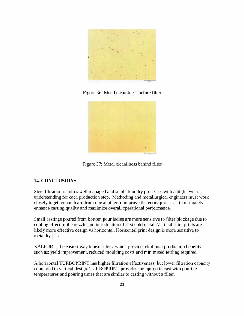
Effective filtration helps to achieve higher metal cleanliness by trapping non-metallic
inclusions created by metal splashing when taping to ladle, de-oxidizing, and pouring.
Well-designed running systems after the filter must provide laminar mould filling as to not
spoil this filtration effect. A sample taken from the filtration unit just before filter [Figure
36] and just after it [Figure 37] demonstrates metal cleanliness improvement.
Although metal cleanliness influences final mechanical properties - foundries are more
focused on variable operating costs like welding cost, which can be quantified and
recorded. It has been proven that filtration reduces fettling & welding cost by 50 – 85 %.
The highest welding reduction is achieved with large castings, less sensitive to hot tear
defects. Filtration cannot reduce linear stress during solidification so hot tears and cracks
cannot be eliminated. However, welding of hot tears in clean metal without sand and slag
inclusions is much easier and faster. Slag and mixed sand might be found often very deep
under the surface of the casting and usually does not float out, which can be challenging
and expensive to weld. Cost for this additional time and effort in cleaning the casting can
be notably reduced by filtration.
21
Figure 36: Metal cleanliness before filter
Figure 37: Metal cleanliness behind filter
14. CONCLUSIONS
Steel filtration requires well managed and stable foundry processes with a high level of
understanding for each production step. Methoding and metallurgical engineers must work
closely together and learn from one another to improve the entire process – to ultimately
enhance casting quality and maximize overall operational performance.
Small castings poured from bottom pour ladles are more sensitive to filter blockage due to
cooling effect of the nozzle and introduction of first cold metal. Vertical filter prints are
likely more effective design vs horizontal. Horizontal print design is more sensitive to
metal by-pass.
KALPUR is the easiest way to use filters, which provide additional production benefits
such as: yield improvement, reduced moulding costs and minimized fettling required.
A horizontal TURBOPRINT has higher filtration effectiveness, but lower filtration capacity
compared to vertical design. TURBOPRINT provides the option to cast with pouring
temperatures and pouring times that are similar to casting without a filter.

22
HOLLOTEX FSt and FH allows for use of filters within ceramic running systems. In-gates
can be positioned at an optimal part of the casting and bottom-filled to achieve laminar
filling without metal splashing, mould erosion, and secondary re-oxidation.
HOLLOTEX CFU is designed to filter the heaviest castings with extremely high metal flow
rates. Running systems must be carefully designed according to existing foundry filtration
experience and metallurgical practice. Care must be given to keep the ceramic running
systems void of sand and other debris.
REFERENCES:
1) Foseco internal investigation
2) Foseco internal studies