Avenir: Managing Data Plane Diversity with Control Plane ...

Cost-Driven Design of a Large Scale X-Plane
Jason R. Welstead*
NASA Langley Research Center, Hampton, VA, 23681, United States of America
Peter C. Frederic�
Tecolote Research, Inc., Santa Barbara, CA, 93111, United States of America
Michael A. Frederick� and Steven R. Jacobson�
NASA Armstrong Flight Research Center, Edwards, CA, 93523, United States of America
Jeffrey J. Berton§
NASA Glenn Research Center, Cleveland, OH, 44135, United States of America
A conceptual design process focused on the development of a low-cost, large scale X-plane was developed as part of an internal research and development effort. One of theconcepts considered for this process was the double-bubble configuration recently developedas an advanced single-aisle class commercial transport similar in size to a Boeing 737-800 orAirbus A320. The study objective was to reduce the contractor cost from contract awardto first test flight to less than $100 million, and having the first flight within three years ofcontract award. Methods and strategies for reduced cost are discussed.
Nomenclature
AR = aspect ratiob = spanCL = lift coefficientCt = target contractor cost to first flightF = cost adjustment factorOEW = operating empty weightS = wing reference areat/c = thickness to chord ratioTOGW = takeoff gross weightWe = target empty weightΛ = wing quarter chord sweep
I. Introduction
Since the 1990’s, NASA has had few large scale, non-military manned experimental planes. With therelease of the 2017 proposed Presidential Budget, a new NASA vision for a series of large scale X-planes
has been laid out called New Aviation Horizons, consisting of as many as five large scale subsonic transportdemonstrators over the next decade. A challenge with any large scale demonstrator is the associated high
*Aerospace Engineer, ASAB, NASA Langley Research Center, 1 N Dryden St. M/S 442, Hampton, VA, 23681, MemberAIAA.
�Chief Scientist, Software Products and Services Group, Tecolote Research, Inc., 5266 Hollister Ave., Ste. 301, SantaBarbara, CA, 93111.
�Aerospace Engineer, Research Engineering Directorate, Aerodynamics and Propulsion Branch, NASA Armstrong FlightResearch Center, PO Box 273, MS 2228, Edwards, CA, 93523.
§Aerospace Engineer, Propulsion Systems Analysis Branch, M/S 5-11, NASA Glenn Research Center, Cleveland, OH, 44135,AIAA Senior Member.
1 of 18
American Institute of Aeronautics and Astronautics
https://ntrs.nasa.gov/search.jsp?R=20170000732 2018-07-15T19:50:22+00:00Z

cost which, in the past, has proven prohibitive for the constrained NASA Aeronautics budget. Even withthe New Aviation Horizons directive and supporting budget, containing cost to a reasonable level requiresappropriate selection of research objectives, scale, and vehicle requirements.
In October 2014, an internal research and development (IRAD) effort started under the ConvergentAeronautics Solutions (CAS) project within the Transformative Aeronautics Concepts Program (TACP) toresearch solutions and approaches on how to design, build, and operate a low cost X-plane. The effort,originally called the Towed X-Plane study, initially had a charter to determine the feasibility of gaining highresearch value at low cost by towing the X-plane, but was later expanded in scope to include towed andself-powered X-plane concepts and renamed the CAS X-plane project. The motivation of the study wasnot to select a specific concept to recommend as a future low-cost X-plane, but rather to employ innovativemethods for cost reduction, identify unintended cost drivers typically associated with requirements, andexplore alternative approaches for technology maturation with acceptable levels of risk. This study couldthen provide invaluable insight to the NASA Aeronautics Research Mission Directorate (ARMD) stakeholdersto enable future X-plane request for proposal (RFP) that is shaped by the low-cost approach.
Ten advanced concepts were initially proposed for the study. To narrow the list of potential conceptsfor study, subject matter experts (SMEs) throughout NASA Aeronautics were consulted to rank the variousconcepts on the following criteria:
� Alignment with ARMD strategic thrusts1
� Degree of need for large scale flight test
� Commercial market entry potential
� Synergy with partners
� Technology readiness level (TRL) progression value
� Complexity and risk
� Concept heritage within NASA
� Vehicle class applicability
� Weight class as a surrogate for cost
� Suitability for towed test technique
� Concept appeal to public
Following the qualitative ranking by the SMEs, the list of ten potential concepts was narrowed to four:hybrid-wing-body, truss-braced-wing, double-bubble, and a modular testbed aircraft. A detailed descriptionof the down select process is beyond the scope of this paper. Each concept was conceptually designed withboth powered and unpowered configurations, with the scale of each configuration driven by concept specificselected research objectives and cost. The design process consisted of two iterations where a concept datapackage was populated and used in the cost estimation process employing a parametric cost estimation tool.
The focus of this paper is the conceptual design of a NASA D8 X-plane (ND8X) where the researchobjectives and cost were the design drivers. The ND8X is a scaled version of the NASA D8 (ND8), an in-houseversion of the D8 concept,2–7 a double-bubble fuselage concept with top-mounted, rear fuselage boundarylayer ingesting engines. Modeling tools for sizing, mission analysis, performance and cost estimates aredescribed in Section II. A full description of the ND8X concept, starting with the development of a full-scalebaseline, is discussed in Section III. Concluding remarks are found in Section IV.
II. Modeling and Cost Estimation Approach
A. Geometry Modeling Using Open Vehicle Sketch Pad
Open Vehicle Sketch Pad (OpenVSP)a is a open source parametric geometry modeler used for a broadrange of applications, but the software’s strength lies in the conceptual modeling of aircraft components.8–16
In this study, OpenVSP was driven through an in-house custom JAVA plug-in for the Phoenix Integration®
ModelCenter v11.2 software. Global design parameters such as wing area (S), span (b), quarter chord sweep(Λ), thickness-to-chord ratio (t/c), and scale factor were provided to OpenVSP by the custom plug-in asdesign variables, and the geometry was automatically updated to reflect the changes. The updated geometryinformation was then fed back to ModelCenter from OpenVSP and used to drive the geometry inputs of theFlight Optimization System (FLOPS)17 sizing and synthesis software discussed in Section II-B.
ahttp://www.openvsp.org
2 of 18
American Institute of Aeronautics and Astronautics
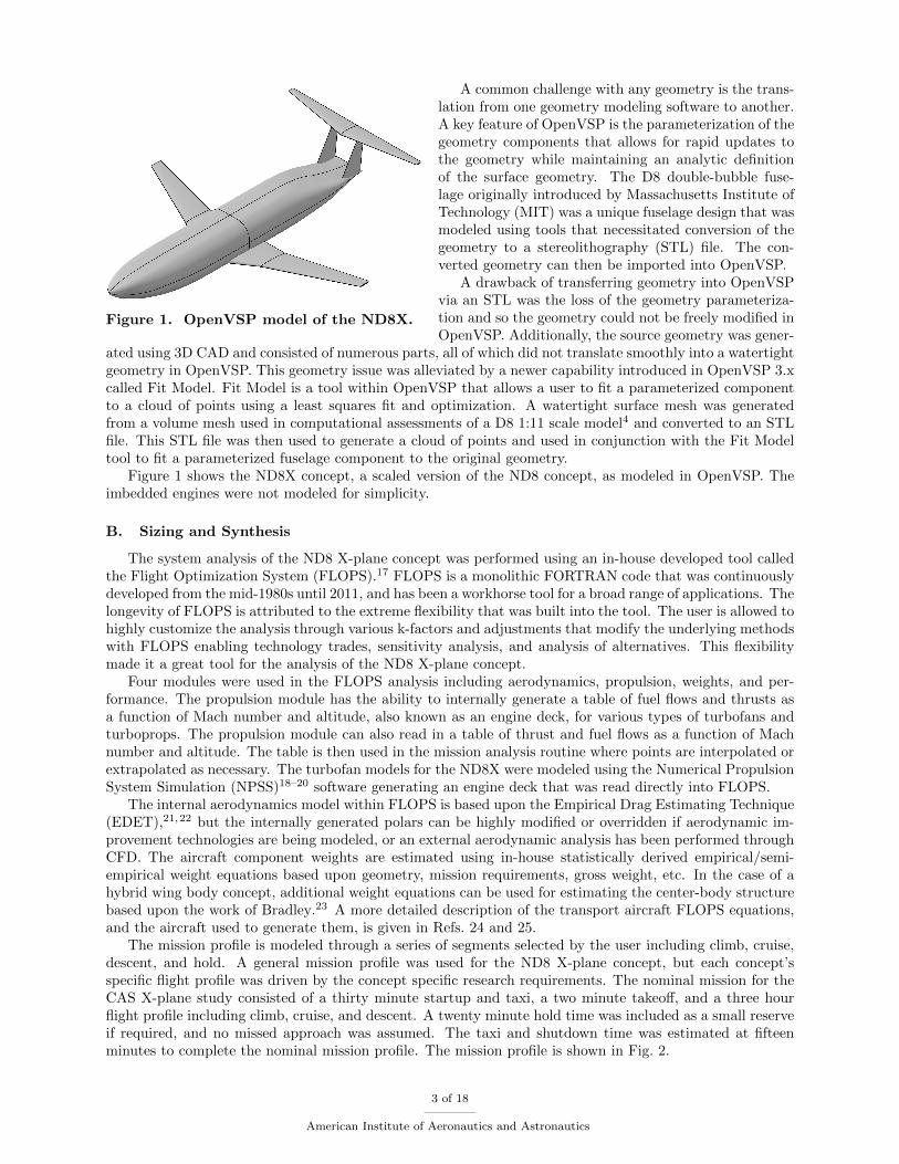
Figure 1. OpenVSP model of the ND8X.
A common challenge with any geometry is the trans-lation from one geometry modeling software to another.A key feature of OpenVSP is the parameterization of thegeometry components that allows for rapid updates tothe geometry while maintaining an analytic definitionof the surface geometry. The D8 double-bubble fuse-lage originally introduced by Massachusetts Institute ofTechnology (MIT) was a unique fuselage design that wasmodeled using tools that necessitated conversion of thegeometry to a stereolithography (STL) file. The con-verted geometry can then be imported into OpenVSP.
A drawback of transferring geometry into OpenVSPvia an STL was the loss of the geometry parameteriza-tion and so the geometry could not be freely modified inOpenVSP. Additionally, the source geometry was gener-
ated using 3D CAD and consisted of numerous parts, all of which did not translate smoothly into a watertightgeometry in OpenVSP. This geometry issue was alleviated by a newer capability introduced in OpenVSP 3.xcalled Fit Model. Fit Model is a tool within OpenVSP that allows a user to fit a parameterized componentto a cloud of points using a least squares fit and optimization. A watertight surface mesh was generatedfrom a volume mesh used in computational assessments of a D8 1:11 scale model4 and converted to an STLfile. This STL file was then used to generate a cloud of points and used in conjunction with the Fit Modeltool to fit a parameterized fuselage component to the original geometry.
Figure 1 shows the ND8X concept, a scaled version of the ND8 concept, as modeled in OpenVSP. Theimbedded engines were not modeled for simplicity.
B. Sizing and Synthesis
The system analysis of the ND8 X-plane concept was performed using an in-house developed tool calledthe Flight Optimization System (FLOPS).17 FLOPS is a monolithic FORTRAN code that was continuouslydeveloped from the mid-1980s until 2011, and has been a workhorse tool for a broad range of applications. Thelongevity of FLOPS is attributed to the extreme flexibility that was built into the tool. The user is allowed tohighly customize the analysis through various k-factors and adjustments that modify the underlying methodswith FLOPS enabling technology trades, sensitivity analysis, and analysis of alternatives. This flexibilitymade it a great tool for the analysis of the ND8 X-plane concept.
Four modules were used in the FLOPS analysis including aerodynamics, propulsion, weights, and per-formance. The propulsion module has the ability to internally generate a table of fuel flows and thrusts asa function of Mach number and altitude, also known as an engine deck, for various types of turbofans andturboprops. The propulsion module can also read in a table of thrust and fuel flows as a function of Machnumber and altitude. The table is then used in the mission analysis routine where points are interpolated orextrapolated as necessary. The turbofan models for the ND8X were modeled using the Numerical PropulsionSystem Simulation (NPSS)18–20 software generating an engine deck that was read directly into FLOPS.
The internal aerodynamics model within FLOPS is based upon the Empirical Drag Estimating Technique(EDET),21,22 but the internally generated polars can be highly modified or overridden if aerodynamic im-provement technologies are being modeled, or an external aerodynamic analysis has been performed throughCFD. The aircraft component weights are estimated using in-house statistically derived empirical/semi-empirical weight equations based upon geometry, mission requirements, gross weight, etc. In the case of ahybrid wing body concept, additional weight equations can be used for estimating the center-body structurebased upon the work of Bradley.23 A more detailed description of the transport aircraft FLOPS equations,and the aircraft used to generate them, is given in Refs. 24 and 25.
The mission profile is modeled through a series of segments selected by the user including climb, cruise,descent, and hold. A general mission profile was used for the ND8 X-plane concept, but each concept’sspecific flight profile was driven by the concept specific research requirements. The nominal mission for theCAS X-plane study consisted of a thirty minute startup and taxi, a two minute takeoff, and a three hourflight profile including climb, cruise, and descent. A twenty minute hold time was included as a small reserveif required, and no missed approach was assumed. The taxi and shutdown time was estimated at fifteenminutes to complete the nominal mission profile. The mission profile is shown in Fig. 2.
3 of 18
American Institute of Aeronautics and Astronautics

Figure 2. Standard mission profile used in the X-plane analysis.
Table 1. Summary of FLOPS input weight assumptions specific to an X-plane.
Group Weight Assumption Comment
Anti-icing 0 lb X-plane will not fly through icing conditions
Air conditioning 500 lb Piloted cockpit only, cooling for crew, avionics, and in-strumentation
Air conditioning 130 lb Unpiloted (avionics/instrumentation need to be cooled)
Instruments 200 lb Based upon 33,000 pound X-plane, scaled based upon X-plane gross weight
Avionics 500 lb Based upon 33,000 pound X-plane, scaled based upon X-plane gross weight
Furnishings 256 lb Includes the furnishings for crew, but not traditional fur-nishings of a commercial transport aircraft
Auxiliary power unit weight 375 lb Weight per auxiliary power unit
Crew 2 Two crew on board, a pilot and flight test engineer
Cargo 500 lb Test instrumentation (min = 200, max = 500)
To ensure commonality in the modeling assumptions between the four X-plane concepts, a standard setof assumptions were made concerning some of the component weights of the vehicle. FLOPS was designedto model aircraft ranging from general aviation, regional and large commercial transports, to fighter aircraft.These types of aircraft contain all the subsystems for standard flight operations of a production vehicle, nota uniquely built X-plane that will not adhere to all operations and certification requirements. To account forthis, some of the inputs for the subsystems and payload weights were modified or overridden based on flighttesting experience of NASA Armstrong Flight Research Center team members. A summary of the weightassumptions are described in Table 1.
C. Parametric Cost Estimation Tool
A parametric cost model called the Probabilistic Technology Investment Ranking System (PTIRS) wasused to estimate the development and production cost of the ND8X. PTIRS is a complete life cycle cost modelfor commercial aircraft development, production, and operations. The PTIRS development and productioncost estimating relations (CERs) are calibrated to reproduce published prices for commercial transportaircraft, given reasonable assumptions regarding amortization of development costs, return on investmentcapital, and manufacturer’s pricing mark-ups. PTIRS operations CERs are derived directly from actualairline operations data from the U.S. Department of Transportation’s Bureau of Transportation Statistics
4 of 18
American Institute of Aeronautics and Astronautics

Figure 3. Sample PTIRS CER.
Form 41 database. The PTIRS CERs are all simple in form, and are all based on current technologies. Forexample, Fig. 3 represents the PTIRS CER for jet engine fan blade production. The CER in Fig. 3 estimatesfirst engine fan blade set production costs based on weight. It is based on a database of 18 engines currentlyin production.
The PTIRS CERs include no subjective adjustment terms that magically address as yet undiscoveredtechnologies. However, the PTIRS CERs differ from other widely-used aircraft cost models such as theRAND DAPCA-III model in that the PTIRS CERs estimate costs at the subsystem, and in some cases theassembly level, whereas DAPCA-III and others estimate costs at the total airframe level. The ability tobreak costs out to lower levels of detail enables the PTIRS tool to accurately reflect the implementationimpacts of new technologies. For non-recurring costs, simple cost adjustment factors are applied directly tothe PTIRS core CER results to reflect design re-use. For example, if a wing design from a prior aircraft is tobe used with minor modifications, and the modifications are judged to be equivalent to 10% of the originaldesign and tooling effort, then a new design factor of 0.1 will be applied to the CER results. Additionaladjustment factors were developed and applied to reflect the unique requirements of flight demonstrationprojects:
� Design requirements for operability, reliability, maintainability, etc. were less stringent.
� Reduced, focused performance requirements and wider design margins allowed less detailed designanalysis.
� High production rate tooling was not required.
� Less stringent production requirements for minimizing weight and wider design margins.
� “Rapid prototyping” fabrication methods with less stringent quality control were acceptable.
� Program management can be streamlined by reduction of reviews and government oversight.
� Engineering documentation requirements were reduced.
These factors were based on proprietary data provided by major airframe developers in the course of previousflight demonstration studies.
A custom data package was used to transfer the vehicle level inputs into the cost analysis. Requiredinformation for the data package included vehicle subsystem weights, fuel and payload weights, static thrustrequirements, and a high level approximation of the use of composites. Salvaged subsystems were indicatedin the data package along with an input for the new design factors, a parameter that captures the amountof design engineering required to integrate that subsystem into the vehicle. Any technologies a weight basedcost estimating relation would not be able to capture, such as an active flow control system, was included inthe data package. The programmatic cost were captured in the data package through the development of aprogram schedule and an estimate of required personnel resources. All the information in the data packagewas then fed to PTIRS for the cost analysis.
5 of 18
American Institute of Aeronautics and Astronautics
0.20
0.25
0.30
0.35
0.40
0.45
0.50
0.55
0.60
0.65
0.70
0 5000 10000 15000 20000 25000
TSFC
, lb/
lb/h
r
Net thrust, lbSLS M0.2164/0M0.3722/10147ft M0.4584/20293ftM0.7202/40587ft
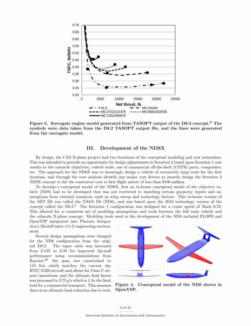
Figure 5. Surrogate engine model generated from TASOPT output of the D8.2 concept.3 Thesymbols were data taken from the D8.2 TASOPT output file, and the lines were generatedfrom the surrogate model.
III. Development of the ND8X
By design, the CAS X-plane project had two iterations of the conceptual modeling and cost estimation.This was intended to provide an opportunity for design adjustments in Iteration 2 based upon Iteration 1 costresults to the research objectives, vehicle scale, use of commercial off-the-shelf (COTS) parts, composites,etc. The approach for the ND8X was to knowingly design a vehicle of excessively large scale for the firstiteration, and through the cost analysis identify any major cost drivers to smartly design the Iteration 2ND8X concept to hit the contractor cost to first flight metric of less than $100 million.
To develop a conceptual model of the ND8X, first an in-house conceptual model of the objective ve-hicle (ND8) had to be developed that was not restricted to matching certain geometry inputs and as-sumptions from external resources, such as wing sweep and technology factors. This in-house version ofthe MIT D8 was called the NASA D8 (ND8), and was based upon the 2010 technology version of theconcept called the D8.2.3 The Iteration 1 configuration was designed for a cruise speed of Mach 0.72.This allowed for a consistent set of modeling assumptions and tools between the full scale vehicle andthe subscale X-plane concept. Modeling tools used in the development of the ND8 included FLOPS and
Figure 4. Conceptual model of the ND8 shown inOpenVSP.
OpenVSP integrated into Phoenix Integra-tion’s ModelCenter v11.2 engineering environ-ment.
Several design assumptions were changedfor the ND8 configuration from the origi-nal D8.2. The taper ratio was increasedfrom 0.135 to 0.35 for improved tip-stallperformance using recommendations fromRaymer,26 the span was constrained to118 feet which matches the current dayB737/A320 aircraft and allows for Class C air-port operations, and the ultimate load factorwas increased to 3.75 g’s which is 1.5x the limitload for a commercial transport. This assumesthere is no ultimate load reduction due to tech-
6 of 18
American Institute of Aeronautics and Astronautics
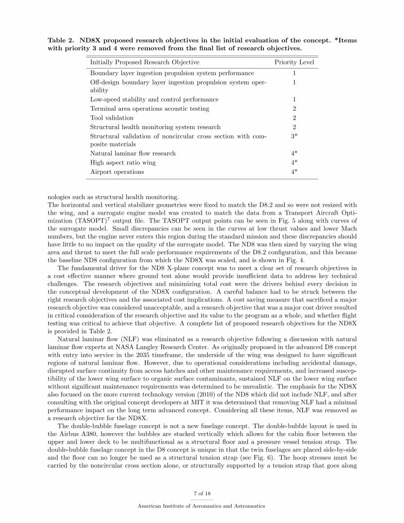
Table 2. ND8X proposed research objectives in the initial evaluation of the concept. *Itemswith priority 3 and 4 were removed from the final list of research objectives.
Initially Proposed Research Objective Priority Level
Boundary layer ingestion propulsion system performance 1
Off-design boundary layer ingestion propulsion system oper-ability
1
Low-speed stability and control performance 1
Terminal area operations acoustic testing 2
Tool validation 2
Structural health monitoring system research 2
Structural validation of noncircular cross section with com-posite materials
3*
Natural laminar flow research 4*
High aspect ratio wing 4*
Airport operations 4*
nologies such as structural health monitoring.The horizontal and vertical stabilizer geometries were fixed to match the D8.2 and so were not resized withthe wing, and a surrogate engine model was created to match the data from a Transport Aircraft Opti-mization (TASOPT)7 output file. The TASOPT output points can be seen in Fig. 5 along with curves ofthe surrogate model. Small discrepancies can be seen in the curves at low thrust values and lower Machnumbers, but the engine never enters this region during the standard mission and these discrepancies shouldhave little to no impact on the quality of the surrogate model. The ND8 was then sized by varying the wingarea and thrust to meet the full scale performance requirements of the D8.2 configuration, and this becamethe baseline ND8 configuration from which the ND8X was scaled, and is shown in Fig. 4.
The fundamental driver for the ND8 X-plane concept was to meet a clear set of research objectives ina cost effective manner where ground test alone would provide insufficient data to address key technicalchallenges. The research objectives and minimizing total cost were the drivers behind every decision inthe conceptual development of the ND8X configuration. A careful balance had to be struck between theright research objectives and the associated cost implications. A cost saving measure that sacrificed a majorresearch objective was considered unacceptable, and a research objective that was a major cost driver resultedin critical consideration of the research objective and its value to the program as a whole, and whether flighttesting was critical to achieve that objective. A complete list of proposed research objectives for the ND8Xis provided in Table 2.
Natural laminar flow (NLF) was eliminated as a research objective following a discussion with naturallaminar flow experts at NASA Langley Research Center. As originally proposed in the advanced D8 conceptwith entry into service in the 2035 timeframe, the underside of the wing was designed to have significantregions of natural laminar flow. However, due to operational considerations including accidental damage,disrupted surface continuity from access hatches and other maintenance requirements, and increased suscep-tibility of the lower wing surface to organic surface contaminants, sustained NLF on the lower wing surfacewithout significant maintenance requirements was determined to be unrealistic. The emphasis for the ND8Xalso focused on the more current technology version (2010) of the ND8 which did not include NLF, and afterconsulting with the original concept developers at MIT it was determined that removing NLF had a minimalperformance impact on the long term advanced concept. Considering all these items, NLF was removed asa research objective for the ND8X.
The double-bubble fuselage concept is not a new fuselage concept. The double-bubble layout is used inthe Airbus A380, however the bubbles are stacked vertically which allows for the cabin floor between theupper and lower deck to be multifunctional as a structural floor and a pressure vessel tension strap. Thedouble-bubble fuselage concept in the D8 concept is unique in that the twin fuselages are placed side-by-sideand the floor can no longer be used as a structural tension strap (see Fig. 6). The hoop stresses must becarried by the noncircular cross section alone, or structurally supported by a tension strap that goes along
7 of 18
American Institute of Aeronautics and Astronautics

the centerline of the fuselage through the passenger cabin. Designing the fuselage structure to handle loadsexperienced in flight along with the pressure load from the cabin pressurization at altitude is a challengingtask. The use of state of the art composites and manufacturing practices, such as automated fiber placement,is envisioned to reduce the structural penalty associated with the noncircular cross section.
Figure 6. Cross-section view ofthe double-bubble fuselage of theD8concept.6
When interfacing with some aircraft fabricators, it was sug-gested that a cost savings could be achieved for the X-plane ifpressurization could be avoided as the vehicle structural re-quirements are reduced, and the required subsystems for pres-surization are eliminated. Additionally, when talking to struc-tural SMEs at NASA Langley Research Center, it was high-lighted that a flight test is not required to validate the struc-tural design, and that there are adequate ground test facilitiesto apply the appropriate loads to validate the noncircular fuse-lage structural design. Given the feedback from the aircraftfabricators to avoid pressurization, and the ample ground testfacilities to properly test the structural design, the research ob-jective to validate the structural design on a noncircular com-posite fuselage in flight was removed. It should be acknowl-edged that the load paths from flight loads measured in flightwould be beneficial for validating the load models, but this was
sacrificed in light of previous discussion.High aspect ratio wing technologies were not a fundamentally enabling technology for the ND8 concept
in that enhancements to transonic wing design and structural efficiency for higher aspect ratios would applyequally to a conventional configuration as it would to the ND8. As such, a more conventional, span restrictedwing was selected as a risk reduction measure and applied the full scale ND8, and then scaled to the ND8X.
A. Iteration 1 ND8X Design
An emphasis was placed on a large scale X-plane, and the selection of the vehicle scale is driven by multiplefactors including the ability to integrate subsystems such as crew accommodations and propulsions systems,vehicle cost correlated to the vehicle empty weight, but most importantly the ability to successfully meetthe research objectives. Based upon feedback from aircraft manufacturers, even with advanced compositematerials and their potential weight reductions, a strong correlation still exists between vehicle cost andempty weight for a one-off vehicle like an X-plane. To successfully meet the boundary layer ingestion (BLI)propulsion system performance research objective, guidance from the testing experts of the Boundary LayerIngesting Inlet Distortion Tolerant Fan (BLI2DTF) wind tunnel test occurring at NASA Glenn ResearchCenter in Fall 2016 emphasized that both Reynolds number and Mach number matching of the full scalevehicle was of utmost importance. Reducing vehicle scale reduces the total vehicle cost, but matching bothReynolds number and Mach becomes increasingly difficult. The ND8X vehicle scale was selected based uponmatching the full scale Mach number, and reducing the testing altitude to match Reynolds number withoutreaching excessive levels of dynamic pressure.
The emphasis for the first iteration of the ND8X configuration was to select a large scale vehicle, mostlylikely too large from a cost perspective, that gave a test flight condition under 25,000 feet, avoiding crewpressurization for the manned vehicle. As part of the CAS X-plane study, a comprehensive trade studywas performed to understand the cost implications of an unmanned versus manned X-plane.27 From theresults of this study, a manned vehicle was chosen as the lower cost option as autonomy was not part of theconcept’s research objectives.
Boundary layer ingestion research was the highest priority and a fundamental enabling technology forthe ND8 concept as a potential future commercial transport. It was known that two design iterations wouldbe performed and design changes could be made after the Iteration 1, so 70% scale was selected which gavea design flight condition of Mach 0.72 at 24,500 feet. With the 70% scale selected, a sensitivity of cost toconcept scale and design could be established which would then drive the Iteration 2 design.
The ND8X was modeled using FLOPS and OpenVSP where the cruise segment of the mission wasconstrained to the target altitude at the design velocity of Mach 0.72, and the cruise length was varied togive a mission endurance of four hours. This was the target endurance that was selected for the Iteration 1ND8X, but was later reduced to three hours in Iteration 2 (see Section III-B) to be consistent with the other
8 of 18
American Institute of Aeronautics and Astronautics

Figure 7. Conceptual geometry for the 70% scale ND8X modeled in OpenVSP.
Table 3. Summary of varied FLOPS inputs to feed the cost estimate.
Input Minimum Most Likely Maximum
Fuselage Structural Weight Factor 0.9 1 1.1
Maximum Mach Number 0.77 0.77 0.82
Instrumentation Payload 200 lb 500 lb 500 lb
Cargo Floor Reinforcement No No Yes
Taxi Out Time 20 min 30 min 45 min
Ultimate Load Factor 2.5 3.75 4.5
X-plane concepts being modeled as part of the CAS X-plane study. An isometric view of the scaled conceptis shown in Fig. 7.
No specific engine was selected for the first iteration of the ND8X, so the surrogate engine model wasscaled to the sea level static thrust required to successfully complete the mission. The surrogate model wasa high bypass ratio turbofan, so scaling this engine model to this extreme means that the thrust lapse, cycleperformance, and thrust specific fuel consumptions (TSFC) were not representative of a turbofan in the 6000lb thrust class. Given that the design would be refined in Iteration 2, and that the additional fuel requireddue to the less efficient, smaller turbofans would have a minor impact on the total vehicle gross weight, thismodeling error was determined to be acceptable at this point in the study.
For the cost estimate it was assumed that several subsystems would be used from donor aircraft orcommercial off the shelf (COTS). The subsystems included landing gear, APU, instrumentation, hydraulics,the flight control subsystem, electrical subsystems, environmental control systems, and a COTS engine thatwas refanned to handle the inflow distortion. This makes the large assumption that an off-the-shelf enginecan be refanned and safely perform in the BLI environment. New design engineering was required for theairframe, the inlet and nacelle, and half of the engine, with new design engineering required to integratethe donated systems and new airframe. All airframe structural components were assumed to be compositematerials except the landing gear.
To complete the cost data package for the concept cost estimate, variations on the inputs were selectedto provide the minimum, most-likely, and maximum values. Since most of the CERs have a weight basedcorrelation, inputs were selected that have an impact on the vehicle structural weight, and therefore thevehicle gross weight. A summary of the varied FLOPS inputs for the cost estimate is provide in Table 3.
A summary of the ND8X design at the end of Iteration 1 is provided in Table 4. From the cost estimate,the ND8X had a total program cost of $446M at the 50% confidence level, and $506M at the 80% confidencelevel. This total program cost includes all government and contractor costs. The contractor cost to firstflight, the key metric for the study, was $394M which well exceeds the target of $100M. Reducing this totalcost requires several design changes that were performed during Iteration 2.
9 of 18
American Institute of Aeronautics and Astronautics
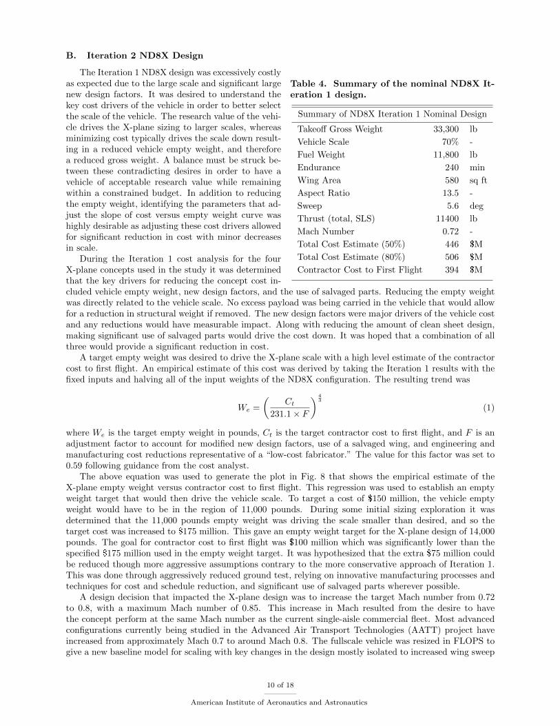
B. Iteration 2 ND8X Design
Table 4. Summary of the nominal ND8X It-eration 1 design.
Summary of ND8X Iteration 1 Nominal Design
Takeoff Gross Weight 33,300 lb
Vehicle Scale 70% -
Fuel Weight 11,800 lb
Endurance 240 min
Wing Area 580 sq ft
Aspect Ratio 13.5 -
Sweep 5.6 deg
Thrust (total, SLS) 11400 lb
Mach Number 0.72 -
Total Cost Estimate (50%) 446 $M
Total Cost Estimate (80%) 506 $M
Contractor Cost to First Flight 394 $M
The Iteration 1 ND8X design was excessively costlyas expected due to the large scale and significant largenew design factors. It was desired to understand thekey cost drivers of the vehicle in order to better selectthe scale of the vehicle. The research value of the vehi-cle drives the X-plane sizing to larger scales, whereasminimizing cost typically drives the scale down result-ing in a reduced vehicle empty weight, and thereforea reduced gross weight. A balance must be struck be-tween these contradicting desires in order to have avehicle of acceptable research value while remainingwithin a constrained budget. In addition to reducingthe empty weight, identifying the parameters that ad-just the slope of cost versus empty weight curve washighly desirable as adjusting these cost drivers allowedfor significant reduction in cost with minor decreasesin scale.
During the Iteration 1 cost analysis for the fourX-plane concepts used in the study it was determinedthat the key drivers for reducing the concept cost in-cluded vehicle empty weight, new design factors, and the use of salvaged parts. Reducing the empty weightwas directly related to the vehicle scale. No excess payload was being carried in the vehicle that would allowfor a reduction in structural weight if removed. The new design factors were major drivers of the vehicle costand any reductions would have measurable impact. Along with reducing the amount of clean sheet design,making significant use of salvaged parts would drive the cost down. It was hoped that a combination of allthree would provide a significant reduction in cost.
A target empty weight was desired to drive the X-plane scale with a high level estimate of the contractorcost to first flight. An empirical estimate of this cost was derived by taking the Iteration 1 results with thefixed inputs and halving all of the input weights of the ND8X configuration. The resulting trend was
We =
(Ct
231.1 × F
) 43
(1)
where We is the target empty weight in pounds, Ct is the target contractor cost to first flight, and F is anadjustment factor to account for modified new design factors, use of a salvaged wing, and engineering andmanufacturing cost reductions representative of a “low-cost fabricator.” The value for this factor was set to0.59 following guidance from the cost analyst.
The above equation was used to generate the plot in Fig. 8 that shows the empirical estimate of theX-plane empty weight versus contractor cost to first flight. This regression was used to establish an emptyweight target that would then drive the vehicle scale. To target a cost of $150 million, the vehicle emptyweight would have to be in the region of 11,000 pounds. During some initial sizing exploration it wasdetermined that the 11,000 pounds empty weight was driving the scale smaller than desired, and so thetarget cost was increased to $175 million. This gave an empty weight target for the X-plane design of 14,000pounds. The goal for contractor cost to first flight was $100 million which was significantly lower than thespecified $175 million used in the empty weight target. It was hypothesized that the extra $75 million couldbe reduced though more aggressive assumptions contrary to the more conservative approach of Iteration 1.This was done through aggressively reduced ground test, relying on innovative manufacturing processes andtechniques for cost and schedule reduction, and significant use of salvaged parts wherever possible.
A design decision that impacted the X-plane design was to increase the target Mach number from 0.72to 0.8, with a maximum Mach number of 0.85. This increase in Mach resulted from the desire to havethe concept perform at the same Mach number as the current single-aisle commercial fleet. Most advancedconfigurations currently being studied in the Advanced Air Transport Technologies (AATT) project haveincreased from approximately Mach 0.7 to around Mach 0.8. The fullscale vehicle was resized in FLOPS togive a new baseline model for scaling with key changes in the design mostly isolated to increased wing sweep
10 of 18
American Institute of Aeronautics and Astronautics

Figure 8. Empirical estimate of empty weight versus high level estimate of contractor cost tofirst flight.
and vehicle structural weight. The horizontal stabilizer and vertical stabilizers were kept fixed for simplicity,but will most likely have to be resized with increased sweep due to the higher Mach number and new wingsweep.
The regression of Fig. 8 assumed that a salvaged wing was been used for the X-plane. Because the ND8concept does not depend on an advanced wing, and because wing development is particularly expensive interms of dollars per pound, the wing was identified as the principal candidate for reuse of legacy hardware.A search of numerous general aviation aircraft was conducted to find a wing that was of relevant size (wingarea and span), certified to a Mach number in excess of 0.8, was a low-wing configuration, and was ona vehicle certified to a higher MTOW than the proposed ND8X concept. The Gulfstream G150 was oneof the few general aviation aircraft that met all the criteria, the most challenging criteria being the hightransonic Mach number. The G150 wing span was approximately 50% scale of the ND8 baseline wingspan,and a comparison of the baseline geometry at half scale (red wing) and the G150 wing (blue wing) is shown
Figure 9. Baseline configuration at 50% scaleshowing the baseline wing (red) and the G150wing (blue). G150 wing was moved forwardfor visual clarity. Note, empennage was un-changed from Iteration 1 for simplicity.
in Fig. 9. The wing weight was estimated using FLOPSto be 2,150 pounds using the G150 gross weight of26,100 pounds. Since the salvaged wing structurewould be fixed and could not be resized, the wingweight was fixed.
Boundary layer ingestion research was of highestpriority (see Table 2) and was not directly dependenton the wing geometry. The ND8X at fifty percent scalewas under the target empty weight discussed previ-ously, so the fuselage and empennage scale to be de-coupled from the wing. This allowed the fuselage andempennage to be sized at 60% scale with the fixed ge-ometry G150 wing giving an empty weight near thetarget of 14,000 pounds.
An engine model of the CF34-8C5 was readily avail-able and was much closer to the relevant engine thrustclass, TSFC, and weight than the originally used D8.2surrogate engine deck of Iteration 1. A sized ND8Xrequired 5,080 pounds of thrust per engine which wasvery similar to a PW305B engine. The PW305B en-gine has half the thrust of a CF34-8C5 engine, butthe cycle was more representative than the surrogatemodel. A specific engine model of the PW305B wouldimprove the accuracy of the vehicle performance and
11 of 18
American Institute of Aeronautics and Astronautics
fuel burn, but would have minimal impact on the finalresult, especially since the TSFC of the scaled engine was adjusted to match the PW305B.
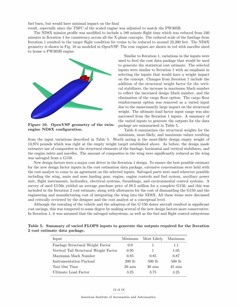
The ND8X mission profile was modified to include a 180 minute flight time which was reduced from 240minutes in Iteration 1 for consistency across all the X-plane concepts. The reduced scale of the fuselage fromIteration 1 resulted in the target flight condition for cruise to be reduced to around 22,200 feet. The ND8Xgeometry is shown in Fig. 10 as modeled in OpenVSP. The rear engines are shown in red with nacelles sizedto house a PW305B engine.
Figure 10. OpenVSP geometry of the twin-engine ND8X configuration.
Similar to Iteration 1, variations in the inputs wereused to feed the cost data package that would be usedto generate the statistical cost estimate. The selectedinputs were similar to Iteration 1 with an emphasis inselecting the inputs that would have a weight impacton the concept. Changes from Iteration 1 include theaddition of the structural weight factor for the verti-cal stabilizers, the increase in maximum Mach numberto reflect the increased design Mach number, and theelimination of the cargo floor option. The cargo floorreinforcement option was removed as a varied inputdue to the unnecessarily large impact on the structuralweight. The ultimate load factor input range was alsonarrowed from the Iteration 1 inputs. A summary ofthe varied inputs to generate the outputs for the datapackage are summarized in Table 5.
Table 6 summarizes the structural weights for theminimum, most-likely, and maximum values resulting
from the input variations described in Table 5. Worth noting is the most-likely design empty weight of13,974 pounds which was right at the empty weight target established above. As before, the design madeextensive use of composites in the structural elements of the fuselage, horizontal and vertical stabilizers, andthe engine inlets and nacelles. The amount of composites in the wing were significantly reduced as the wingwas salvaged from a G150.
New design factors were a major cost driver in the Iteration 1 design. To ensure the best possible estimatefor the new design factor inputs in the cost estimation data package, extensive conversations were held withthe cost analyst to come to an agreement on the selected inputs. Salvaged parts were used wherever possibleincluding the wing, main and nose landing gear, engine, engine controls and fuel system, auxiliary powerunit, flight instruments, hydraulics, electrical systems, furnishings, and environmental control systems. Asurvey of used G150s yielded an average purchase price of $8.5 million for a complete G150, and this wasincluded in the Iteration 2 cost estimate, along with allowances for the cost of dismantling the G150 and theengineering and manufacturing cost of integrating the wing into the ND8X. All these items were discussedand critically reviewed by the designer and the cost analyst at a conceptual level.
Although the rescaling of the vehicle and the adoption of the G-150 donor aircraft resulted in significantcost savings, this was tempered to some degree by making several of the new design factors more conservative.In Iteration 1, it was assumed that the salvaged subsystems, as well as the fuel and flight control subsystems
Table 5. Summary of varied FLOPS inputs to generate the outputs required for the Iteration2 cost estimate data package.
Input Minimum Most Likely Maximum
Fuselage Structural Weight Factor 0.9 1 1.1
Vertical Tail Structural Weight Factor 0.95 1 1.05
Maximum Mach Number 0.85 0.85 0.87
Instrumentation Payload 200 lb 500 lb 500 lb
Taxi Out Time 20 min 30 min 45 min
Ultimate Load Factor 3.25 3.75 4.25
12 of 18
American Institute of Aeronautics and Astronautics
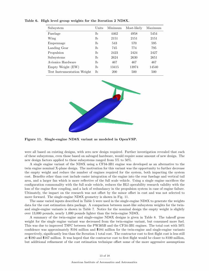
Table 6. High level group weights for the Iteration 2 ND8X.
Subsystem Units Minimum Most-likely Maximum
Fuselage lb 4462 4958 5454
Wing lb 2151 2151 2151
Empennage lb 543 570 595
Landing Gear lb 745 774 795
Propulsion lb 2423 2424 2427
Subsystems lb 2624 2630 2651
Avionics Hardware lb 467 467 467
Empty Weight (EW) lb 13415 13974 14540
Test Instrumentation Weight lb 200 500 500
Figure 11. Single-engine ND8X variant as modeled in OpenVSP.
were all based on existing designs, with zero new design required. Further investigation revealed that eachof these subsystems, even those based on salvaged hardware, would require some amount of new design. Thenew design factors applied to these subsystems ranged from 5% to 50%.
A single engine variant of the ND8X using a CF34-3B1 engine was developed as an alternative to thetwin engine nominal X-plane design. The motivation for this variant was the opportunity to further decreasethe empty weight and reduce the number of engines required for the system, both impacting the systemcost. Benefits other than cost include easier integration of the engine into the rear fuselage and vertical tailarea, and a larger fan which is more reflective of the full scale vehicle. Using a single engine sacrifices theconfiguration commonality with the full scale vehicle, reduces the BLI operability research validity with theloss of the engine flow coupling, and a lack of redundancy in the propulsion system in case of engine failure.Ultimately, the impact on the research was not offset by the minor offset in cost and was not selected tomove forward. The single-engine ND8X geometry is shown in Fig. 11.
The same varied inputs described in Table 5 were used in the single-engine ND8X to generate the weightsdata for the cost estimation data package. A comparison between most-like subsystem weights for the twin-and single-engine variants is shown in Table 7. Notice for the nominal design the empty weight is slightlyover 13,000 pounds, nearly 1,000 pounds lighter than the twin-engine ND8X.
A summary of the twin-engine and single-engine ND8X designs is given in Table 8. The takeoff grossweight for the single engine variant was decreased from the twin-engine variant, but consumed more fuel.This was due to improved TSFC between the PW305B and the CF34-3B1 engines. The total cost with 50%confidence was approximately $194 million and $184 million for the twin-engine and single-engine variantsrespectively, significantly less than the Iteration 1 total cost. The contractor cost to first flight cost is less stillat $180 and $167 million. It was hoped that the contractor cost to first flight would be closer to $100 million,but additional refinement of the cost estimation technique offset some of the more aggressive assumptions
13 of 18
American Institute of Aeronautics and Astronautics

Table 7. Comparison of the twin- and single-engine ND8X most-likely subsystem weights.
Subsystem Units Twin Single
Fuselage lb 4958 4733
Wing lb 2151 2151
Empennage lb 570 565
Landing Gear lb 774 748
Propulsion lb 2424 2089
Subsystems lb 2630 2302
Avionics Hardware lb 467 467
Empty Weight (EW) lb 13974 13055
Test Instrumentation Weight lb 500 500
Figure 12. Cumulative probably distribution of total project cost for the twin-engine ND8X.
that were made in Iteration 2. A detailed breakout of cost estimate including the project management costcan be seen in Table 9, and a cumulative probability distribution of the total project cost is shown in Fig. 12with markers shown for the 50% and 80% confidence level costs. It should also be noted that the finalcontractor cost to first flight fell very close to the initial estimate using the regression shown in Eq 1.
IV. Conclusions
A conceptual model of a large scale configuration with a double-bubble fuselage with top-mounted bound-ary layer ingesting engines called the ND8X was designed. This design effort was part of a much larger studycalled the Convergent Aeronautic Solutions (CAS) X-plane study under the Transformative AeronauticsConcepts Program (TACP) at NASA. As part of this study, four configuration were modeled to develop alow-cost approach to design, build, and test a large scale X-plane where the contractor cost to first flight wasless than $100 million, of which the ND8X concept was one of the configurations. Achieving the researchobjectives of the X-plane was the major design driver while trying to find innovative low-cost solutions.Additional efforts in the CAS X-plane study include a broad range of trade studies to identify cost drivers,one of which was a trade of a manned versus unmanned concept. Through this particular trade study, itwas determined that a manned system was more effective for a large scale ND8X.
Particular emphasis should be placed an establishing a set clear research objectives where flight test isthe best or only way to achieve the research objectives. Excess research objectives will result in an increasedset of requirements, requirements drive vehicle weight, and vehicle weight drives cost.
Two design iterations were performed on the ND8X. A vehicle scale of 70% was selected for the first
14 of 18
American Institute of Aeronautics and Astronautics
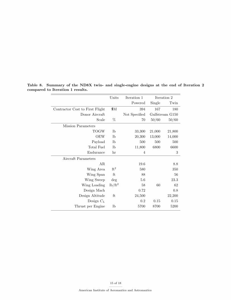
Table 8. Summary of the ND8X twin- and single-engine designs at the end of Iteration 2compared to Iteration 1 results.
Units Iteration 1 Iteration 2
Powered Single Twin
Contractor Cost to First Flight $M 394 167 180
Donor Aircraft Not Specified Gulfstream G150
Scale % 70 50/60 50/60
Mission Parameters
TOGW lb 33,300 21,000 21,800
OEW lb 20,300 13,000 14,000
Payload lb 500 500 500
Total Fuel lb 11,800 6800 6600
Endurance hr 4 3
Aircraft Parameters
AR 19.6 8.8
Wing Area ft2 580 350
Wing Span ft 88 56
Wing Sweep deg 5.6 23.3
Wing Loading lb/ft2 58 60 62
Design Mach 0.72 0.8
Design Altitude ft 24,500 22,200
Design CL 0.2 0.15 0.15
Thrust per Engine lb 5700 8700 5200
15 of 18
American Institute of Aeronautics and Astronautics

Table 9. Detailed costs breakdown for the Iteration 2 twin- and single-engine ND8X at the0.5 probability in FY2015$K.
Contractor Cost to First Flight Total Project Cost
2 Engines 1 Engine 2 Engines 1 Engine
X-Plane Project 180,475 167,637 197,158 184,311
Project Management 7,274 6,757 7,408 6,891
Project Analysis - - 8,757 8,757
Advanced Concepts - - 887 887
Technology Development 173,201 160,880 173,201 160,880
Air Vehicle 171,711 159,391 171,711 159,391
Vehicle Integration 18,727 17,519 18,727 17,519
Donor Aircraft 16,146 12,468 16,146 12,468
Airframe 75,336 73,017 75,336 73,017
Fuselage 51,929 49,684 51,929 49,684
Wing 4,360 4,373 4,360 4,373
Empennage 18,455 18,385 18,455 18,385
Landing Gear 592 575 592 575
Propulsion 24,218 21,406 24,218 21,406
Subsystems 31,680 29,353 31,680 29,353
Avionics Hardware 1,901 1,906 1,901 1,906
Software 3,703 3,722 3,703 3,722
Test Instrumentation 1,489 1,489 1,489 1,489
Validation & Test - - 6,905 6,896
iteration resulting in a vehicle contractor cost to first flight of $394M. As expected, the cost far exceededthe goal of $100M. The Iteration 1 design was then used to identify the major cost drivers that could thenbe used in the Iteration 2 ND8X design. The Iteration 2 design was scaled down to a selected target emptyweight and made extensive use of salvaged parts including a wing from a Gulfstream G150 business jet.This resulted in a fuselage and empennage that was at 60% scale and a wing that was at 50% scale. Asingle engine variant of the ND8X was explored as a potential lower cost savings, but resulted in vehicle withreduced research value. As such, the twin-engine variant of the ND8X was preferred and had a contractorcost to first flight of $180M. The Iteration 2 ND8X cost was significantly reduced from the Iteration 1 design,but fell short of the study goal. There is still opportunity for reduced vehicle cost by reducing the fuselageand empennage scale from 60% and this could be explored in future studies.
Acknowledgments
The authors would like to thank Craig Nickol of the NASA Langley Research Center for coordinating thedesign team leads as part of the CAS X-Plane study while providing design decision support, Shishir Pandyaof the NASA Ames Research Center for generating a stereolithography (STL) file from the CFD mesh ofthe D8 wind tunnel model, and Rob McDonald for generating the OpenVSP fuselage component from theSTL file using OpenVSP’s Fit Model. This work was funded under the Convergent Aeronautics Solutionsproject, under the Transformative Aeronautics Concepts Program at NASA.
References
1 “NASA Aeronautics Strategic Implementation Plan,” 2014.
2 Drela, M., “Development of the D8 Transport Configuration,” 29th AIAA Applied Aerodynamics Confer-ence, American Institute of Aeronautics and Astronautics, Honolulu, HA, June 2011, pp. 1–14, AIAA-
16 of 18
American Institute of Aeronautics and Astronautics

2011-3970.
3 Uranga, A., Drela, M., Greitzer, E. M., Titchener, N. A., Lieu, M. K., Siu, N. M., and Huang, A. C.,“Preliminary Experimental Assessment of the Boundary Layer Ingesting Benefit for the D8 Aircraft,”52nd Aerospace Sciences Meeting , American Institute of Aeronautics and Astronautics, National Harbor,MD, January 2014, pp. 1–25, AIAA-2014-0906.
4 Pandya, S. A., Huang, A., Espitia, A., and Uranga, A., “Computational Assessment of the BoundaryLayer Ingesting Nacelle Design of the D8 Aircraft,” 52nd Aerospace Sciences Meeting , American Instituteof Aeronautics and Astronautics, National Harbor, MD, January 2014, pp. 1–14, AIAA-2014-0907.
5 Pandya, S. A., “External Aerodynamics Simulations for the MIT D8 “Double-Bubble” Aircraft Design,”Seventh International Conference on Computational Fluid Dynamics, Big Island, HA, July 2012, pp. 1–16,ICCFD7-4304.
6 Greitzer, E. M., et al., “N+3 Aircraft Concept Designs and Trade Studies, Final Report,” ContractorReport Volume I, National Aeronautics and Space Administration, 2010, NASA/CR-2010-216794.
7 Greitzer, E. M., et al., “N+3 Aircraft Concept Designs and Trade Studies, Final Report,” ContractorReport Volume II, National Aeronautics and Space Administration, 2010, NASA/CR-2010-216794.
8 Hahn, A. S., “Vehicle Sketch Pad: A Parametric Geometry Modeler for Conceptual Aircraft Design,”48th AIAA Aerospace Sciences Meeting , American Insittue of Aeronautics and Astronautics, Orlando,FL, 2010, pp. 1 – 11, AIAA-2010-0657.
9 Hahn, A. S., “Vehicle Sketch Pad Aircraft Modeling Strategies,” 61st AIAA Aerospace Sciences Meeting ,American Insittue of Aeronautics and Astronautics, Grapevine, TX, 2013, pp. 1 – 9, AIAA-2013-0331.
10 Fredericks, W. J., Antcliff, K. R., Costa, G., Deshpande, N., Moore, M. D., San Miguel, E. A., and Snyder,A. N., “Aircraft Conceptual Design Using Vehicle Sketch Pad,” 48th AIAA Aerospace Sciences Meeting ,American Institute of Aeronautics and Astronautics, Orlando, FL, January 2010, pp. 1–17, AIAA-2010-0658.
11 Belben, J. B. and McDonald, R. A., “Enabling Rapid Conceptual Design Using Geometry-Based Multi-Fidelity Models In VSP,” 51st AIAA Aerospace Sciences Meeting , American Institue of Aeronautics andAstronautics, Grapevine, TX, January 2013, pp. 1–13, AIAA-2013-0328.
12 Olson, E. D., “Three-Dimensional Modeling of Aircraft High-Lift Components with Vehicle Sketch Pad,”54th AIAA Aerospace Sciences Meeting , American Institute of Aeronautics and Astronautics, San Diego,CA, January 2016, pp. 1–14, AIAA-2016-1274.
13 Waddington, M. J. and McDonald, R. A., “Development of an Interactive Wave Drag Capability forthe OpenVSP Parametric Geometry Tool,” 15th AIAA Aviation Technology, Integration, and OperationsConference, American Institute of Aeronautics and Astronautics, Dallas, TX, June 2015, pp. 1–11, AIAA-2015-2548.
14 Gary, A. M. and McDonald, R. A., “Parametric Identification of Surface Regions in OpenVSP for ImprovedEngineering Analysis,” 53rd AIAA Aerospace Sciences Meeting , American Institute of Aeronautics andAstronautics, Kissimmee, FL, January 2015, pp. 1–13, AIAA-2015-1016.
15 McDonald, R. A., “Interactive Reconstruction of 3D Models in the OpenVSP Parametric Geometry Tool,”53rd AIAA Aerospace Sciences Meeting , American Institute of Aeronautics and Astronautics, Kissimmee,FL, January 2015, pp. 1–10, AIAA-2015-1014.
16 Gloudemans, J. R. and McDonald, R. A., “User Defined Components in the OpenVSP Parametric Geom-etry Tool,” 15th AIAA Aviation Technology, Integration, and Operations Conference, American Instituteof Aeronautics and Astronautics, Dallas, TX, June 2015, pp. 1–7, AIAA-2015-2547.
17 McCullers, L., “Aircraft Configuration Optimization Including Optimized Flight Profiles,” Proceedings ofthe Symposium on Recent Experiences in Multidisciplinary Analysis and Optimization, No. NASA CP-2327, 1984, pp. 395–412.
17 of 18
American Institute of Aeronautics and Astronautics

18 Lytle, J., “The Numerical Propulsion System Simulation: An Overview,” Technical Memo NASA TM-2000-209915, NASA, 2000.
19 NPSS Consortium, NPSS User Guide Software Release: 2.3.0 , The Ohio Aerospace Institute, Cleveland,OH, 2010.
20 NPSS Consortium and NASA Glenn Research Center, NPSS Reference Sheets Software Release: NPSS1.6.5 , NASA, Cleveland, OH, 2008.
21 Elliott, R. D., “Empirical Drag Estimation Technique (EDET) User’s Manual,” Company Report LR28788, Lockheed-California, December 1978.
22 Feagin, R. C. and Morrison, W. D., “Delta Method, An Empirical Drag Buildup Technique,” ContractorReport NASA/CR-151971, Lockheed-California Co., Burbank, CA, December 1978.
23 Bradley, K. R., “A Sizing Methodology for the Conceptual Design of Blended-Wing-Body Transports,”Contractor Report NASA/CR-2004-213016, NASA Langley Research Center, Hampton, VA, 2004.
24 Welstead, J., Conceptual Design Optimization of an Augmented Stability Aircraft Incorporating DynamicResponse Performance Constraints, Ph.D. thesis, Auburn University, 2014.
25 Wells, D. P., Horvath, B. L., and McCullers, L. A., “The Flight Optimization System PreliminaryWeights Estimation Method,” Technical Memo NASA TM-2016-XXXXXX, NASA Langley Research Cen-ter, Hampton, VA, 2016, (submitted for publication).
26 Raymer, D. P., Aircraft Design: A Conceptual Approach, 3rd ed., American Institute of Aeronautics andAstronautics, Reston, VA, 2006.
27 Lechniak, J. A. and Melton, J. E., “Manned vs. Unmanned Considerations for Future X-planes,” Aviationand Aeronautics Forum and Exposition, American Insitute of Aeronautics and Astronautics, Denver, CO,June 2017, (submitted for publication).
18 of 18
American Institute of Aeronautics and Astronautics