Cossar, C. and Popescu, M. and Miller, T.J.E. and McGilp ...
9
Cossar, C. and Popescu, M. and Miller, T.J.E. and McGilp, M.I. and Olaru, M. (2008) A general magnetic-energy-based torque estimator: validation via a permanent-magnet motor drive. IEEE Transactions on Industry Applications 44(4):pp. 1210-1217. http://eprints.gla.ac.uk/4545/ 12 th August 2008 Glasgow ePrints Service https://eprints.gla.ac.uk
Transcript of Cossar, C. and Popescu, M. and Miller, T.J.E. and McGilp ...

Cossar, C. and Popescu, M. and Miller, T.J.E. and McGilp, M.I. and Olaru, M. (2008) A general magnetic-energy-based torque estimator: validation via a permanent-magnet motor drive. IEEE Transactions on Industry Applications 44(4):pp. 1210-1217.
http://eprints.gla.ac.uk/4545/ 12th August 2008
Glasgow ePrints Service https://eprints.gla.ac.uk

1210 IEEE TRANSACTIONS ON INDUSTRY APPLICATIONS, VOL. 44, NO. 4, JULY/AUGUST 2008
A General Magnetic-Energy-BasedTorque Estimator: Validation via aPermanent-Magnet Motor Drive
Calum Cossar, Mircea Popescu, Senior Member, IEEE, T. J. E. Miller, Fellow, IEEE,Malcolm McGilp, and Mircea Olaru
Abstract—This paper describes the use of the current–flux-linkage (i−ψ) diagram to validate the performance of a gen-eral magnetic-energy-based torque estimator. An early step in thetorque estimation is the use of controller duty cycles to reconstructthe average phase-voltage waveform during each pulsewidth-modulation (PWM) switching period. Samples over the funda-mental period are recorded for the estimation of the averagetorque. The fundamental period may not be an exact multipleof the sample time. For low speed, the reconstructed voltagerequires additional compensation for inverter-device losses. Ex-perimental validation of this reconstructed waveform with theactual PWM phase-voltage waveform is impossible due to thefact that one is PWM in nature and the other is the averagevalue during the PWM period. A solution to this is to determinethe phase flux-linkage using each waveform and then plot theresultant i−ψ loops. The torque estimation is based on instanta-neous measurements and can therefore be applied to any electricalmachine. This paper includes test results for a three-phase interiorpermanent-magnet brushless ac motor operating with both sinu-soidal and nonsinusoidal current waveforms.
Index Terms—Brushless permanent-magnet (PM) motor drives,electromagnetic average torque, torque estimator.
I. INTRODUCTION
IN THE last decade, brushless permanent-magnet (PM)motor drives have been widely used in many industrial
applications such as robots, rolling mills, or machine tools. Theadvantages of these machines include high power density, lowinertia, and high-speed capabilities. However, the control per-formance of the PM motors is greatly affected by the uncertain-ties related to the motor parameters, external load disturbance,and unmodeled and nonlinear dynamics [3]. Advanced controltechniques such as nonlinear control [4], adaptive control [5],robust control [6], variable structure control, and intelligent
Paper IPCSD-MT08-02, presented at the 2006 Industry Applications SocietyAnnual Meeting, Tampa, FL, October 8–12, and approved for publication in theIEEE TRANSACTIONS ON INDUSTRY APPLICATIONS by the Industrial DrivesCommittee of the IEEE Industry Applications Society. Manuscript submittedfor review November 4, 2006 and released for publication December 6, 2007.Published July 23, 2008 (projected).
C. Cossar, M. Popescu, T. J. E. Miller, and M. McGilp are with the SPEEDLaboratory, Department of Electronics and Electrical Engineering, Univer-sity of Glasgow, Glasgow, G12 8LT, U.K. (e-mail: [email protected];[email protected]; [email protected]; [email protected]).
M. Olaru is with ICNDMF-CEFIN, 70314 Bucharest, Romania (e-mail:[email protected]).
Color versions of one or more of the figures in this paper are available onlineat http://ieeexplore.ieee.org.
Digital Object Identifier 10.1109/TIA.2008.926231
control have been developed. However, the overall stability maynot be guaranteed in these schemes due to certain assump-tions introduced, complicated controller design, and feedbacklinearization.
This paper proposes a new torque estimator that can be usedfor online measurement of the average torque for any type ofbrushless PM motor drive. From the phase-current and phase-voltage measurements, the flux-linkage values are estimated.With phase currents and flux linkages available, the averagetorque is estimated online with high accuracy. The proposedestimator avoids the classical dq transformation [4], [6] and,thus, is applicable to any PM motor drive, regardless of thecontrol strategy, winding distribution, saturation level, and/ornumber of slots/pole. This robust scheme may be implementedin a digital signal processor (DSP) and used not only for mea-surement of the average torque without any torque transducersbut it may be successfully implemented in any torque controllerthat requires the average torque estimation. The proposed algo-rithm is validated experimentally and theoretically through theusage of the i−ψ diagram.
II. MATHEMATICAL MODEL
The method of energy functional variation, which uses aderivative of the magnetic energy with respect to position atconstant flux linkages or the derivative of magnetic coenergywith respect to position at constant current to compute theelectromagnetic torque, is generally accepted as a method wellsuited for torque estimation [1], [2].
The instantaneous electromagnetic torque may be found asa derivative of the magnetic energy with respect to position atconstant flux linkages or the derivative of magnetic coenergywith respect to position at constant current
Te = −∂W
∂θ
∣∣∣∣ψ=ct
=∂W ′
∂θ
∣∣∣∣i=ct
. (1)
The total magnetic-field energy produced by a system ofn coils having the flux linkages ψ1, ψ2, . . . , ψn and thecurrents i1, i2, . . . , in is given by
W + W ′ =n∑
k=1
ikψk. (2)
In a conservative (lossless) system, this energy equals the sumof the magnetostatic energy of the system (i.e., motor) and the
0093-9994/$25.00 © 2008 IEEE

COSSAR et al.: GENERAL MAGNETIC-ENERGY-BASED TORQUE ESTIMATOR: VALIDATION VIA PM MOTOR DRIVE 1211
mechanical work
∆(W + W ′) =
(n∑
k=1
ik∆ψk +n∑
k=1
ψk∆ik
)
= ∆Wm + Te∆θ. (3)
From (1)–(3), if we neglect the stored magnetostatic energy, weobtain
Te =12·
n∑k=1
ik∆ψk
∣∣∣∣i=ct
∆θ− 1
2·
n∑k=1
ψk∆ik
∣∣∣∣ψ=ct
∆θ. (4)
By integrating over a fundamental cycle, we can obtain theaverage electromagnetic torque
Tavg =1
2T∆θ·
T∫0
(n∑
k=1
ik∆ψk −n∑
k=1
ψk∆ik
)dt. (5)
If we use the relation
ψk =
T∫0
(vk − rkik)dt (6)
and dividing a fundamental cycle in N samples, expression (5)becomes
Tavg =p
2π·
N∑i=1
n∑
k=1
ik∆n∑
j=1
(vj − rkij)k
−n∑
k=1
∆ik
n∑j=1
(vj − rkij)k
. (7)
Relation (7) suggests that, if the phase currents and volt-ages are measured online, a general torque estimator may beimplemented for any motor type. When demonstrating (7), noassumption was made to restrict this approach to a certain motortype or to a linear system. This paper is dedicated to the imple-mentation and validation of a new torque estimator based on (7)to the PM motor drives. The average electromagnetic torqueis equivalent to the torque predicted by the i−ψ diagram [1]or the flux–MMF diagram [2] and is proportional to the areaenclosed by the i−ψ locus over one fundamental cycle
Tavg =mp
2π∆W ′ (8)
where ∆W ′ is the coenergy or energy converted per phaseduring the fundamental period, m is the number of phases, andp is the number of pole pairs.
III. AVERAGE TORQUE ESTIMATOR
The proposed average torque estimation is based around therelationship between coenergy and average torque. As we haveseen, the coenergy is proportional to the area enclosed by the
i−ψ locus over one fundamental cycle, but it can also be calcu-lated from measuring the energy supplied to the phase over onefundamental cycle and subtracting the energy loss associatedwith the phase resistance. Given a digital implementation usinghigh-frequency sampling, the total energy supplied to the phaseduring a fundamental cycle is
(W )cycle =
(N∑0
iphvph
)τcycle (9)
where N is the number of samples in one fundamental cycleand τcycle is the fundamental period.
The resistive energy loss over one complete cycle is given by
WCu = (Irms)2Rphτcycle. (10)
(Irms)2 is equivalent to the mean-squared current and, in asampling system, can be calculated for any current waveformas follows:
(Irms)2 =1N
[N∑0
(iph)2]
. (11)
Hence, corresponding to the fundamental cycle, the phase-energy/coenergy variation can be calculated using the followingexpression and then substituted in (8):
∆W ′ =
(N∑0
iphvph
)τcycle −
1N
(N∑0
(iph)2)
Rphτcycle.
(12)
In measurement terms, the torque estimator is thereforerequired to sample the phase current and phase voltage everyswitching period over a complete fundamental cycle and alsodetermine the time taken for the fundamental cycle and therelated number of samples during this time. It is worthwhileconsidering the effects on precision when the fundamentalperiod is not an integral number of samples. For a 50-µs sampleperiod, there are 1200 samples for a motor speed of 1000 r/min;similarly for 3600 r/min, there are 333 samples; therefore,the effect becomes more significant as the speed increases. Ifhigh-speed operation is required, then the solution would be todecrease the sample period; for the test platform described inthe next section, a sample period of 10 µs is achievable.
The torque estimator is implemented on a general-purposemotor control platform which may be used to implement arange of control strategies for brushless PM and switched-reluctance machines. The controller is based on a low-costTI C280 150-MHz 32-bits fixed-point DSP; a summary of itsapplicable hardware peripherals being as follows: synchronizedsix-phase 12-bits pulsewidth-modulation (PWM) outputs at20 kHz; dedicated incremental encoder interface; 16–12-bitsanalog-to-digital converter channels; and asynchronous andsynchronous communication ports. The controller hardwarealso includes a four-channel 12-bits digital-to-analog converterto allow analog representations of controller parameters suchas sampled phase currents to be output to an oscilloscope.This becomes very useful in facilitating the validation of the

1212 IEEE TRANSACTIONS ON INDUSTRY APPLICATIONS, VOL. 44, NO. 4, JULY/AUGUST 2008
Fig. 1. Experimental test stand.
Fig. 2. Controller and torque estimator for a PMAC motor.
torque estimator as described later. The motor-control strategiesand associated torque estimator are all implemented in DSPsoftware with an inner current/torque control loop running at20 kHz. Note that, as the torque estimator is using instantaneousmeasurements and the subsequent calculations are based onstored-energy conservation, the technique can be applied toany electrical machine—for example, brushless PM, induction,and switched-reluctance motors. The bandwidth response ofthis torque estimator limits its application to the case of drivesystems where it is required to find an optimized high-efficiencysteady-state operating point.
IV. EXPERIMENTAL TESTS AND VALIDATION
Experimental tests are carried out on a three-phase wye-connected PM ac motor running with both sinusoidal andnonsinusoidal phase currents. A photograph of the experimentaltest rig is shown in Fig. 1. The laboratory test machine is a
TABLE ITHREE-PHASE INVERTER SWITCHING STATES
Fig. 3. Example of the PWM switching pattern.
fractional horsepower two-pole machine developed for use inan electrical appliance.
An outline of the interior PM (IPM) ac-motor control strategy(for one phase only) and the associated torque estimator isshown in Fig. 2. The basic requirement of the controller is
COSSAR et al.: GENERAL MAGNETIC-ENERGY-BASED TORQUE ESTIMATOR: VALIDATION VIA PM MOTOR DRIVE 1213
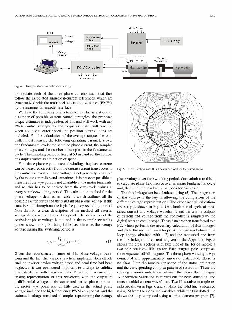
Fig. 4. Torque-estimation validation test rig.
to regulate each of the three phase currents such that theyfollow the associated sinusoidal-current references, which aresynchronized with the rotor-back electromotive forces (EMFs),by the incremental encoder interface.
We have the following points to note. 1) This is just one ofa number of possible current-control strategies; the proposedtorque estimator is independent of this and will work with anyPWM control strategy. 2) The torque estimator will functionwhen additional outer speed and position control loops areincluded. For the calculation of the average torque, the con-troller must measure the following operating parameters overone fundamental cycle: the sampled phase current, the sampledphase voltage, and the number of samples in the fundamentalcycle. The sampling period is fixed at 50 µs, and so, the numberof samples varies as a function of speed.
For a three-phase wye-connected winding, the phase currentscan be measured directly from the output current transducers inthe controller/inverter. Phase voltage is not generally measuredby the motor controller, and sometimes, it is not even possible tomeasure if the wye point is not available at the motor terminals,and so, this has to be derived from the duty-cycle values atevery sample/switching period. The calculation method for thephase voltage is detailed in Table I, which outlines all thepossible switch states and the resultant phase-one voltage if thisstate is valid throughout the high-frequency switching period.Note that, for a clear description of the method, all invertervoltage drops are omitted at this point. The derivation of theequivalent phase voltage is outlined in the example switchingpattern shown in Fig. 3. Using Table I as reference, the averagevoltage during this switching period is
vph =VDC
3τsw(t2 − t1). (13)
Given the reconstructed nature of this phase-voltage wave-form and the fact that various practical implementation effectssuch as inverter-device voltage drops and dead time had beenneglected, it was considered important to attempt to validatethis calculation with measured data. Direct comparison of ananalog representation of this waveform with the output ofa differential-voltage probe connected across phase one andthe motor wye point was of little use, as the actual phasevoltage included the high-frequency PWM component, and theestimated voltage consisted of samples representing the average
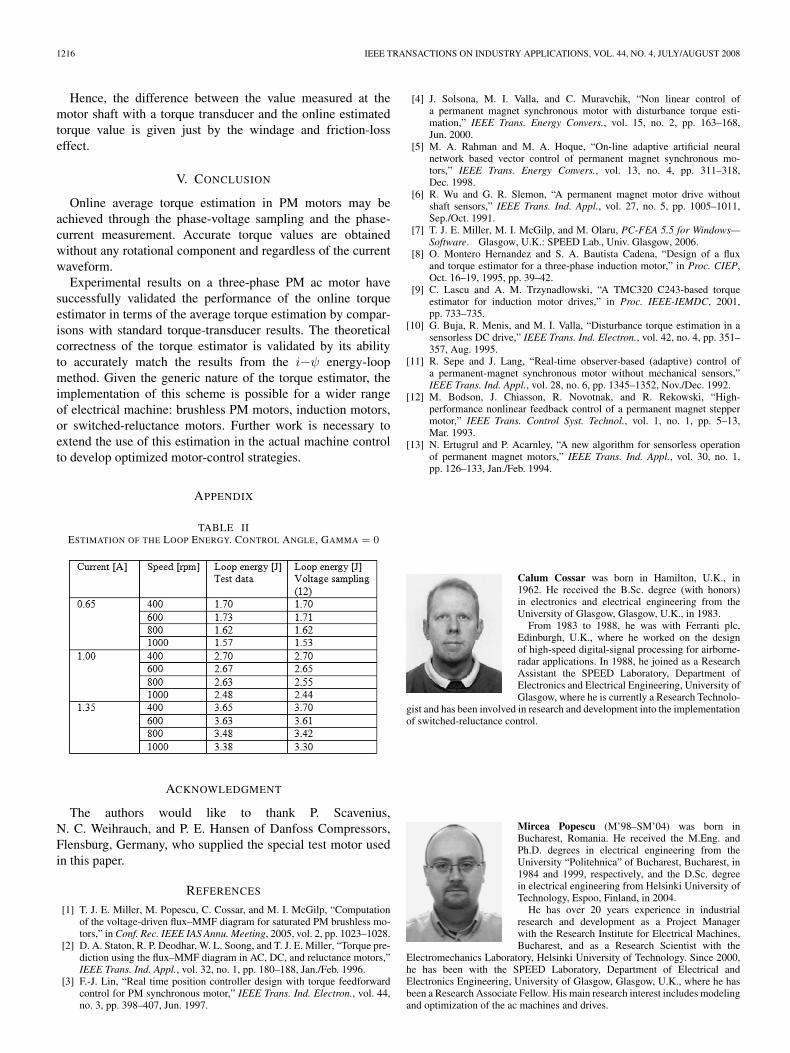
Fig. 5. Cross section with flux lines under load for the tested motor.
phase voltage over the switching period. One solution to this isto calculate phase flux linkage over an entire fundamental cycleand, then, plot the resultant i−ψ loops for each case.
The flux linkage can be calculated using (5). The integrationof the voltage is the key in allowing the comparison of thedifferent voltage representations. The experimental validation-test setup is shown in Fig. 4. One fundamental cycle of mea-sured current and voltage waveforms and the analog outputsof current and voltage from the controller is sampled by thedigital storage oscilloscope. These data are then transferred to aPC, which performs the necessary calculation of flux linkagesand plots the resultant i−ψ loops. A comparison between theloop energy obtained with (12) and the measured one fromthe flux linkage and current is given in the Appendix. Fig. 5shows the cross section with flux plot of the tested motor: atwo-pole brushless IPM motor. Each magnet pole comprisesthree separate NdFeB magnets. The three-phase winding is wyeconnected and approximately sinewave distributed. There isno skew. Note the noncircular shape of the stator laminationand the corresponding complex pattern of saturation. These arecausing a minor imbalance between the phase flux linkages.A theoretical validation is carried out for both sinusoidal andnonsinusoidal current waveforms. Two illustrative example re-sults are shown in Figs. 6 and 7, where the solid line is obtainedusing (5) from the measured variables, while the thin dotted lineshows the loop computed using a finite-element program [7].

1214 IEEE TRANSACTIONS ON INDUSTRY APPLICATIONS, VOL. 44, NO. 4, JULY/AUGUST 2008
Fig. 6. (a) Sinusoidal current waveform. (b) Flux-linkage waveform forsinusoidal phase current. (c) i−ψ loop for sinusoidal phase current.
There is a close correlation of the i−ψ loops for both operatingcases, both in terms of the resultant area of the loops and, moreimportantly, in terms of the shape of the loops. An experimentalvalidation is carried out to compare online estimated torquewith measured torque from a rotational torque transducer. Ini-tial results are shown in Fig. 8(a), highlighting the increasing er-ror in the online torque measurement as the speed is decreased.
Fig. 7. (a) Nonsinusoidal current waveform. (b) Flux-linkage waveform fornonsinusoidal phase current. (c) i−ψ loop for nonsinusoidal phase current.
A subsequent modification to the torque estimation to includea fixed voltage drop due to inverter-device losses during the“0 V” switching states improved performance considerably, asshown in Fig. 8(b). The “0 V” states are increasingly dominantat low speed due to the reduced-voltage requirements, so evenalthough the device voltage drops are low, the time spent in

COSSAR et al.: GENERAL MAGNETIC-ENERGY-BASED TORQUE ESTIMATOR: VALIDATION VIA PM MOTOR DRIVE 1215
Fig. 8. Comparison of estimated versus measured torque values for sinusoidalphase currents with control angle (gamma) = 0. (a) No voltage compensationduring “0 V” switching states. (b) Voltage compensation during “0 V” switch-ing states.
these states becomes significant, and compensation is increas-ingly required. Very low speed testing (< 100 r/min) was notpossible with this machine due to dynamometer limitations, butit is expected that voltage compensation becomes even morecritical in this speed range with the possible need for a morecomplex compensation strategy as compared to the presentedfixed voltage drop set by the peak current.
This, however, would not be relevant in the main applicationof this technique; to optimize, online, the efficiency of variable-speed drives at any given operating point.
The possibility of extracting and displaying the informationrelated to the i−ψ loops from the data stored by the onlinetorque estimator represents a very useful diagnosis tool. Weget a measure of the torque ripple from the loop shape, andany unbalanced condition on the stator winding can be tracedif the i−ψ loops per phase are not identical in shape andarea. As the estimated values through the online estimatoralgorithm described at Section III are practically identical withthose obtained through the i−ψ loop area (7), further resultsshow just the comparison between the measured torque values(torque transducer) and the estimated torque values with theonline estimator. Fig. 8 shows the torque variation with speed
Fig. 9. Sinusoidal current case. Torque versus control angle (gamma) withspeed = 700 r/min and voltage compensation during “0 V” switching states.
Fig. 10. Nonsinusoidal current case. Torque versus speed without voltagecompensation during “0 V” switching states.
for three sinewave current levels, with amplitudes 1, 1.5, and2 A and with current phasor aligned with the back EMF phasor,i.e., control angle (gamma) is zero. Note the difference due tothe compensation voltage factor at low speed.
Fig. 9 shows the average torque variation for a sinusoidalcurrent waveform with 2-A peak value, 700 r/min, and variouscontrol-angle (gamma) ranges.
For a complete analysis, the flux-weakening region re-sults are shown in Fig. 10, when the current waveform isnonsinusoidal.
As motor speed increases, the required phase voltages tomaintain sinusoidal phase currents also increases such that,at a given speed, the voltage demand exceeds that which ispossible from the inverter/dc link; the result being increaseddistortion on the phase current waveforms, an example of whichis shown in Fig. 7(a). Note that this condition is limited tohigh-speed operation, and thus, the “0 V” compensation haslittle effect and torque estimation is equivalent with and withoutthis compensation.
It is important to observe that, for all cases, once the torqueis known, it is possible to achieve even the speed from a powerbalance similar to (11).
1216 IEEE TRANSACTIONS ON INDUSTRY APPLICATIONS, VOL. 44, NO. 4, JULY/AUGUST 2008
Hence, the difference between the value measured at themotor shaft with a torque transducer and the online estimatedtorque value is given just by the windage and friction-losseffect.
V. CONCLUSION
Online average torque estimation in PM motors may beachieved through the phase-voltage sampling and the phase-current measurement. Accurate torque values are obtainedwithout any rotational component and regardless of the currentwaveform.
Experimental results on a three-phase PM ac motor havesuccessfully validated the performance of the online torqueestimator in terms of the average torque estimation by compar-isons with standard torque-transducer results. The theoreticalcorrectness of the torque estimator is validated by its abilityto accurately match the results from the i−ψ energy-loopmethod. Given the generic nature of the torque estimator, theimplementation of this scheme is possible for a wider rangeof electrical machine: brushless PM motors, induction motors,or switched-reluctance motors. Further work is necessary toextend the use of this estimation in the actual machine controlto develop optimized motor-control strategies.
APPENDIX
TABLE IIESTIMATION OF THE LOOP ENERGY. CONTROL ANGLE, GAMMA = 0
ACKNOWLEDGMENT
The authors would like to thank P. Scavenius,N. C. Weihrauch, and P. E. Hansen of Danfoss Compressors,Flensburg, Germany, who supplied the special test motor usedin this paper.
REFERENCES
[1] T. J. E. Miller, M. Popescu, C. Cossar, and M. I. McGilp, “Computationof the voltage-driven flux–MMF diagram for saturated PM brushless mo-tors,” in Conf. Rec. IEEE IAS Annu. Meeting, 2005, vol. 2, pp. 1023–1028.
[2] D. A. Staton, R. P. Deodhar, W. L. Soong, and T. J. E. Miller, “Torque pre-diction using the flux–MMF diagram in AC, DC, and reluctance motors,”IEEE Trans. Ind. Appl., vol. 32, no. 1, pp. 180–188, Jan./Feb. 1996.
[3] F.-J. Lin, “Real time position controller design with torque feedforwardcontrol for PM synchronous motor,” IEEE Trans. Ind. Electron., vol. 44,no. 3, pp. 398–407, Jun. 1997.
[4] J. Solsona, M. I. Valla, and C. Muravchik, “Non linear control ofa permanent magnet synchronous motor with disturbance torque esti-mation,” IEEE Trans. Energy Convers., vol. 15, no. 2, pp. 163–168,Jun. 2000.
[5] M. A. Rahman and M. A. Hoque, “On-line adaptive artificial neuralnetwork based vector control of permanent magnet synchronous mo-tors,” IEEE Trans. Energy Convers., vol. 13, no. 4, pp. 311–318,Dec. 1998.
[6] R. Wu and G. R. Slemon, “A permanent magnet motor drive withoutshaft sensors,” IEEE Trans. Ind. Appl., vol. 27, no. 5, pp. 1005–1011,Sep./Oct. 1991.
[7] T. J. E. Miller, M. I. McGilp, and M. Olaru, PC-FEA 5.5 for Windows—Software. Glasgow, U.K.: SPEED Lab., Univ. Glasgow, 2006.
[8] O. Montero Hernandez and S. A. Bautista Cadena, “Design of a fluxand torque estimator for a three-phase induction motor,” in Proc. CIEP,Oct. 16–19, 1995, pp. 39–42.
[9] C. Lascu and A. M. Trzynadlowski, “A TMC320 C243-based torqueestimator for induction motor drives,” in Proc. IEEE-IEMDC, 2001,pp. 733–735.
[10] G. Buja, R. Menis, and M. I. Valla, “Disturbance torque estimation in asensorless DC drive,” IEEE Trans. Ind. Electron., vol. 42, no. 4, pp. 351–357, Aug. 1995.
[11] R. Sepe and J. Lang, “Real-time observer-based (adaptive) control ofa permanent-magnet synchronous motor without mechanical sensors,”IEEE Trans. Ind. Appl., vol. 28, no. 6, pp. 1345–1352, Nov./Dec. 1992.
[12] M. Bodson, J. Chiasson, R. Novotnak, and R. Rekowski, “High-performance nonlinear feedback control of a permanent magnet steppermotor,” IEEE Trans. Control Syst. Technol., vol. 1, no. 1, pp. 5–13,Mar. 1993.
[13] N. Ertugrul and P. Acarnley, “A new algorithm for sensorless operationof permanent magnet motors,” IEEE Trans. Ind. Appl., vol. 30, no. 1,pp. 126–133, Jan./Feb. 1994.
Calum Cossar was born in Hamilton, U.K., in1962. He received the B.Sc. degree (with honors)in electronics and electrical engineering from theUniversity of Glasgow, Glasgow, U.K., in 1983.
From 1983 to 1988, he was with Ferranti plc,Edinburgh, U.K., where he worked on the designof high-speed digital-signal processing for airborne-radar applications. In 1988, he joined as a ResearchAssistant the SPEED Laboratory, Department ofElectronics and Electrical Engineering, University ofGlasgow, where he is currently a Research Technolo-
gist and has been involved in research and development into the implementationof switched-reluctance control.
Mircea Popescu (M’98–SM’04) was born inBucharest, Romania. He received the M.Eng. andPh.D. degrees in electrical engineering from theUniversity “Politehnica” of Bucharest, Bucharest, in1984 and 1999, respectively, and the D.Sc. degreein electrical engineering from Helsinki University ofTechnology, Espoo, Finland, in 2004.
He has over 20 years experience in industrialresearch and development as a Project Managerwith the Research Institute for Electrical Machines,Bucharest, and as a Research Scientist with the
Electromechanics Laboratory, Helsinki University of Technology. Since 2000,he has been with the SPEED Laboratory, Department of Electrical andElectronics Engineering, University of Glasgow, Glasgow, U.K., where he hasbeen a Research Associate Fellow. His main research interest includes modelingand optimization of the ac machines and drives.

COSSAR et al.: GENERAL MAGNETIC-ENERGY-BASED TORQUE ESTIMATOR: VALIDATION VIA PM MOTOR DRIVE 1217
T. J. E. Miller (M’74–SM’82–F’96) was born inWigan, U.K. He received the B.Sc. degree from theUniversity of Glasgow, Glasgow, U.K., and the Ph.D.degree from the University of Leeds, Leeds, U.K.
From 1979 to 1986, he was an Electrical Engi-neer and Program Manager with GE Research andDevelopment, Schenectady, NY. His industrial ex-perience includes periods with GEC (U.K.), BritishGas, International Research and Development, anda student apprenticeship with Tube Investments Ltd.He is currently a Professor of electrical power engi-
neering and Founder and Director of the SPEED Consortium with the SPEEDLaboratory, Department of Electronics and Electrical Engineering, Universityof Glasgow. He is the author of over 100 publications in the fields of motors,drives, power systems, and power electronics, including seven books.
Prof. Miller is a Fellow of the Institution of Electrical Engineers, U.K.
Malcolm McGilp was born in Helensburgh, U.K., in1965. He received the B.Eng. degree (with honors) inelectronic systems and microcomputer engineeringfrom the University of Glasgow, Glasgow, U.K.,in 1987.
From 1987 to 1996, he was a Research Assis-tant with the SPEED Laboratory, Department ofElectronics and Electrical Engineering, University ofGlasgow, where he has been a Research Associatesince 1996. He is responsible for the software archi-tecture of the SPEED motor-design software and has
developed the interface and user facilities, which allow it to be easy to learn andintegrate with other PC-based software.
Mircea Olaru received the M.Sc. degree inmathematics from Bucharest University, Bucharest,Romania.
He has more than 35 years experience in finite-element analysis in electromagnetics and mechan-ics. He is currently an Analyst and Programmerwith ICNDMF-CEFIN, Bucharest. He has authored35 published articles and has presented 54 essays atnational and international scientific meetings.