COSC 393: Lecture 2 Radio Fundamentals. Radio Communication Radio signals Spectrum Transmitter...
40
COSC 393: Lecture 2 Radio Fundamentals
-
Upload
lee-charles -
Category
Documents
-
view
225 -
download
2
Transcript of COSC 393: Lecture 2 Radio Fundamentals. Radio Communication Radio signals Spectrum Transmitter...
COSC 393: Lecture 2
Radio Fundamentals
Radio Communication
• Radio signals
• Spectrum
• Transmitter
• Signal propagation
• Modulation
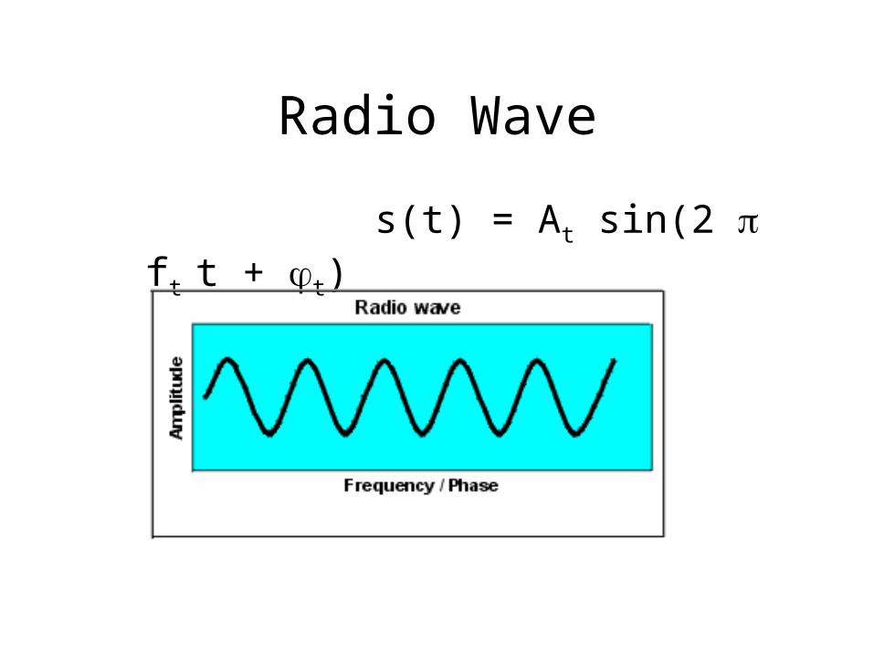
Radio Wave
s(t) = At sin(2 ft t + t)

Frequency and Wave length
• Relationship:
= c/f
• wave length ,
• speed of light c 3x10⁸m/s,
• frequency f
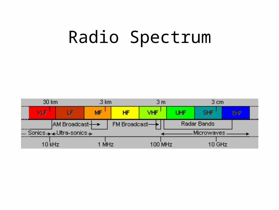
Radio Spectrum
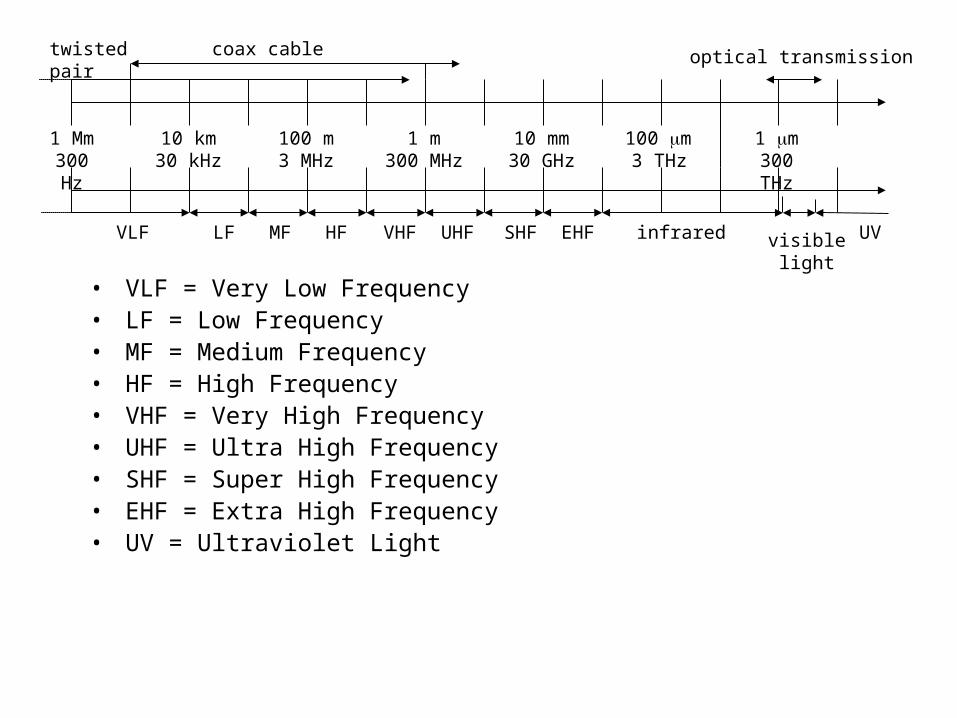
• VLF = Very Low Frequency• LF = Low Frequency • MF = Medium Frequency• HF = High Frequency• VHF = Very High Frequency• UHF = Ultra High Frequency• SHF = Super High Frequency• EHF = Extra High Frequency• UV = Ultraviolet Light
1 Mm300 Hz
10 km30 kHz
100 m3 MHz
1 m300 MHz
10 mm30 GHz
100 m3 THz
1 m300 THz
visible lightVLF LF MF HF VHF UHF SHF EHF infrared UV
optical transmissioncoax cabletwisted pair
• Isotropic radiator: Equal radiation in all directions (3D) - theoretical antenna
• Real antennas always have directive effects (vertically and/or horizontally)
• Different antennas have different radiation pattern.
Antennas
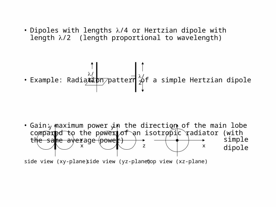
• Dipoles with lengths /4 or Hertzian dipole with length /2 (length proportional to wavelength)
• Example: Radiation pattern of a simple Hertzian dipole
• Gain: maximum power in the direction of the main lobe compared to the power of an isotropic radiator (with the same average power)
side view (xy-plane)
x
y
side view (yz-plane)
z
y
top view (xz-plane)
x
z
simpledipole
/4 /2

side view (xy-plane)
x
y
side view (yz-plane)
z
y
top view (xz-plane)
x
z
top view, 3 sector
x
z
top view, 6 sector
x
z
• Often used for base stations in a cellular system (e.g., covering a valley)
directedantenna
sectorizedantenna
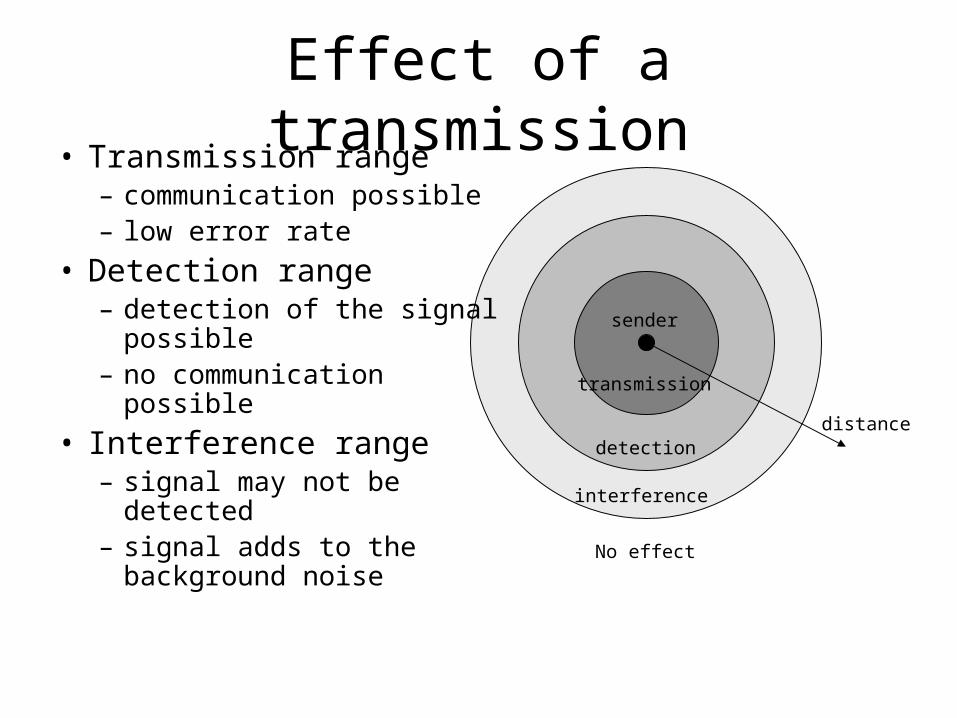
Effect of a transmission
distance
sender
transmission
detection
interference
• Transmission range– communication possible– low error rate
• Detection range– detection of the signal
possible– no communication
possible
• Interference range– signal may not be
detected – signal adds to the
background noise
No effect
Signal propagation property
• Radio signal behaves like light in free space (straight line)
• Receiving power proportional to 1/d² (d = distance between sender and receiver)
• So ideally, the transmitter and a receiver must see each other!
Really?
Three means of propagation
• Ground wave
• Tropospheric wave
• Ionospheric or sky wave
Ground Wave
• travels in contact with earth’s surface• reflection, refraction and scattering by objects on
the ground• transmitter and receiver need NOT see each other• affects all frequencies• at VHF or higher, provides more reliable
propagation means• signal dies off rapidly as distance increases

Tropospheric Wave
• bending(refraction) of wave in the lower atmosphere
• VHF communication possible over a long distance
• bending increases with frequency – so higher frequency more chance of propagation
• More of an annoyance for VHF or UHF (cellular)
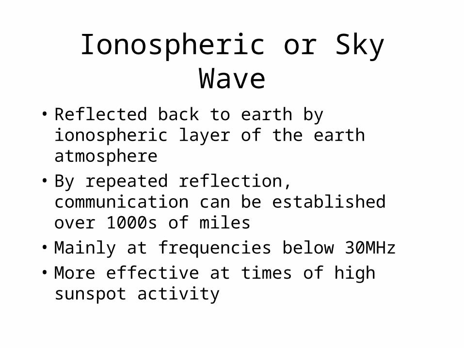
Ionospheric or Sky Wave
• Reflected back to earth by ionospheric layer of the earth atmosphere
• By repeated reflection, communication can be established over 1000s of miles
• Mainly at frequencies below 30MHz
• More effective at times of high sunspot activity

reflection
scattering
diffraction
shadowing
4 possible events
Radio wave Radio wave
Radio wave
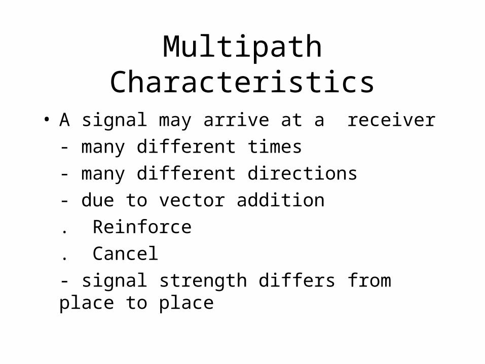
Multipath Characteristics
• A signal may arrive at a receiver
- many different times
- many different directions
- due to vector addition
. Reinforce
. Cancel
- signal strength differs from place to place
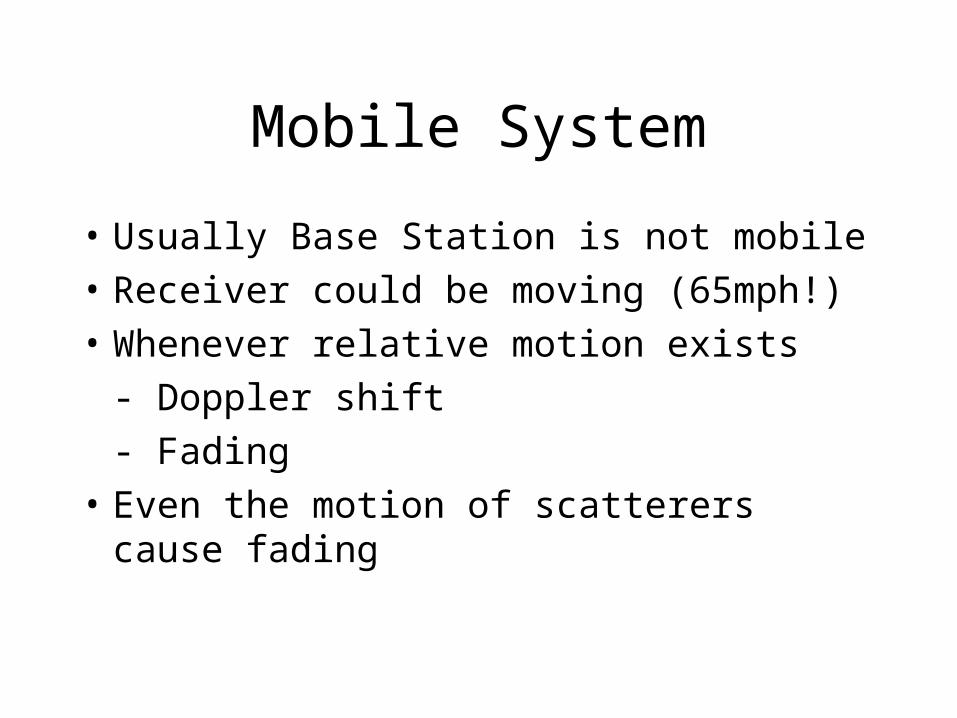
Mobile System
• Usually Base Station is not mobile
• Receiver could be moving (65mph!)
• Whenever relative motion exists
- Doppler shift
- Fading
• Even the motion of scatterers cause fading
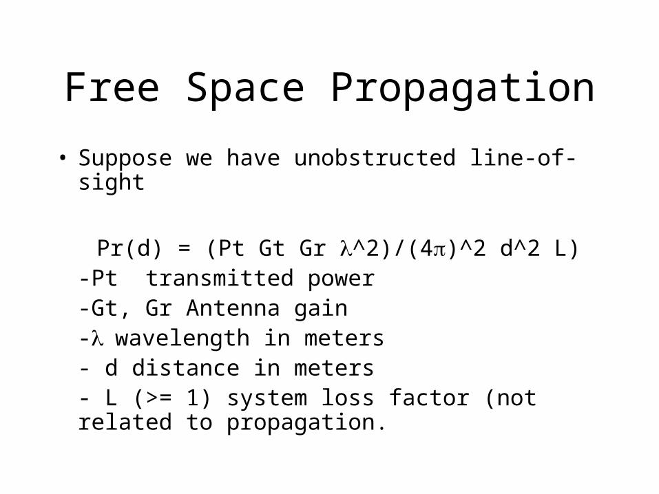
Free Space Propagation
• Suppose we have unobstructed line-of-sight
Pr(d) = (Pt Gt Gr ^2)/(4)^2 d^2 L)-Pt transmitted power-Gt, Gr Antenna gain-wavelength in meters- d distance in meters- L (>= 1) system loss factor (not related to propagation.

Propagation Losses
• Two major components
- Long term fading m(t)
- Short term fading r(t)
Received signal s(t)
s(t) = m(t) r(t)

dB - decibel
• Decibel, a logarithmic unit of intensity used to indicated power lost or gained between two signals. Named after Alexander Graham Bell.
10 log (P1/P2)

Radio Signal Fading
T
Sig
nal s
tre n
g th
(dB
)
Time
Long term fading
Short term fading
Short term fading
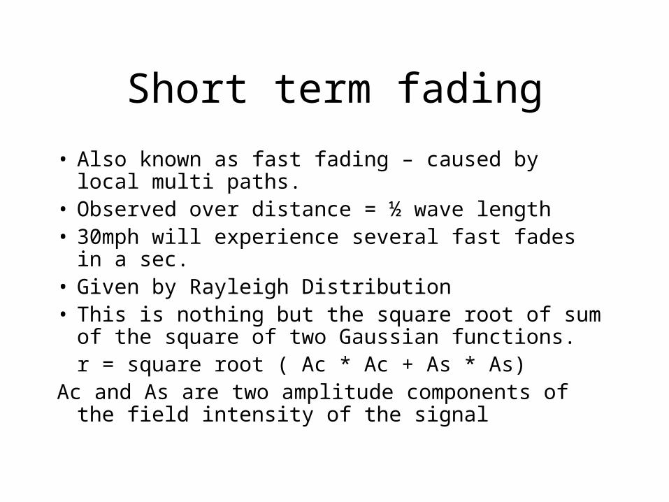
• Also known as fast fading – caused by local multi paths.
• Observed over distance = ½ wave length• 30mph will experience several fast fades in a sec.• Given by Rayleigh Distribution• This is nothing but the square root of sum of the
square of two Gaussian functions.r = square root ( Ac * Ac + As * As)
Ac and As are two amplitude components of the field intensity of the signal

Long term fading
• Long term variation in mean signal level is also known as slow fading
• Caused by movement over large distances.• The probability density function is given by
a log-normal distribution- normal distribution on a log scale
P(m) = (1/m (m) 2) e^[-(log m – E(m))^2/(2 (m)^2)]
Delay Spread
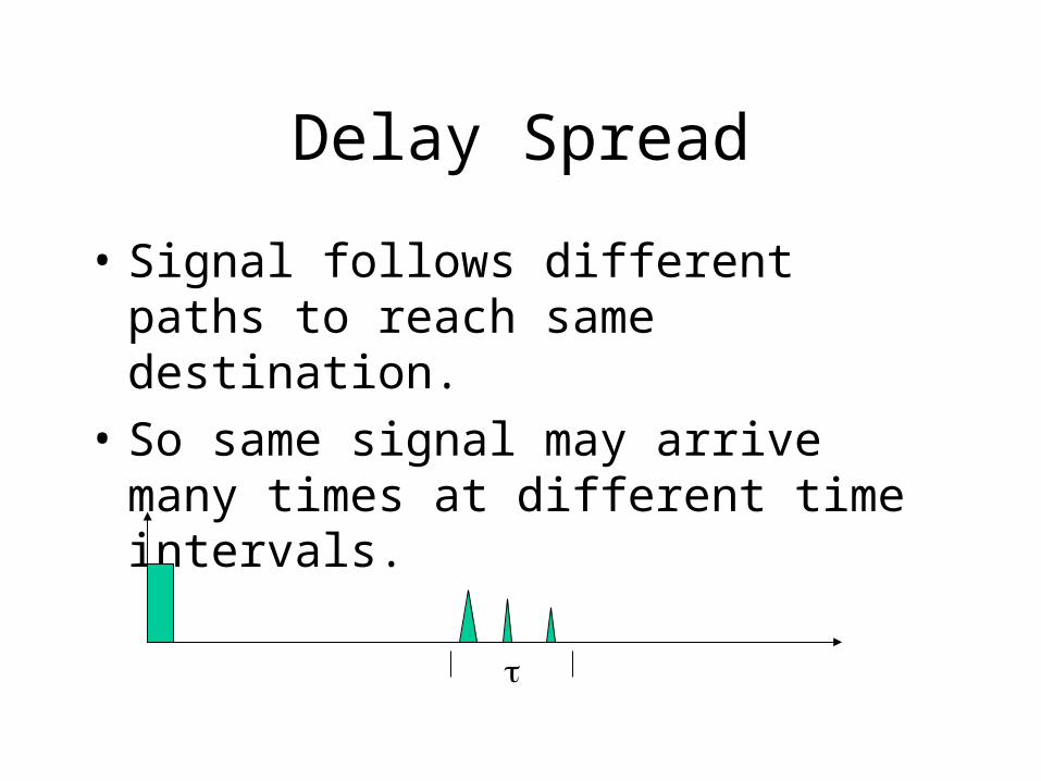
• Signal follows different paths to reach same destination.
• So same signal may arrive many times at different time intervals.
Delay Spread
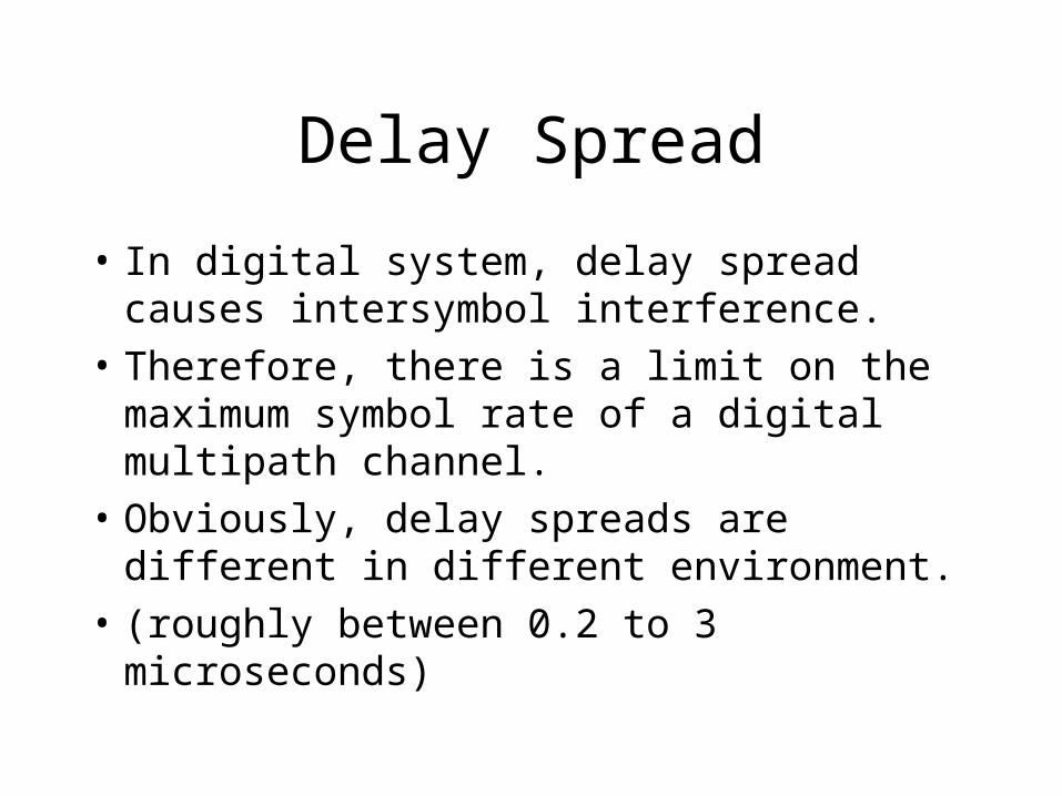
• In digital system, delay spread causes intersymbol interference.
• Therefore, there is a limit on the maximum symbol rate of a digital multipath channel.
• Obviously, delay spreads are different in different environment.
• (roughly between 0.2 to 3 microseconds)

Capacity of Channel
• What is the maximum transmission rate so that the channel has very high reliability?
- error free capacity of a channel
• C.E. Shannon’s work suggest that signaling scheme exists for error-free transmission if the rate of transmission is lower than the channel capacity.
Shannon’s work
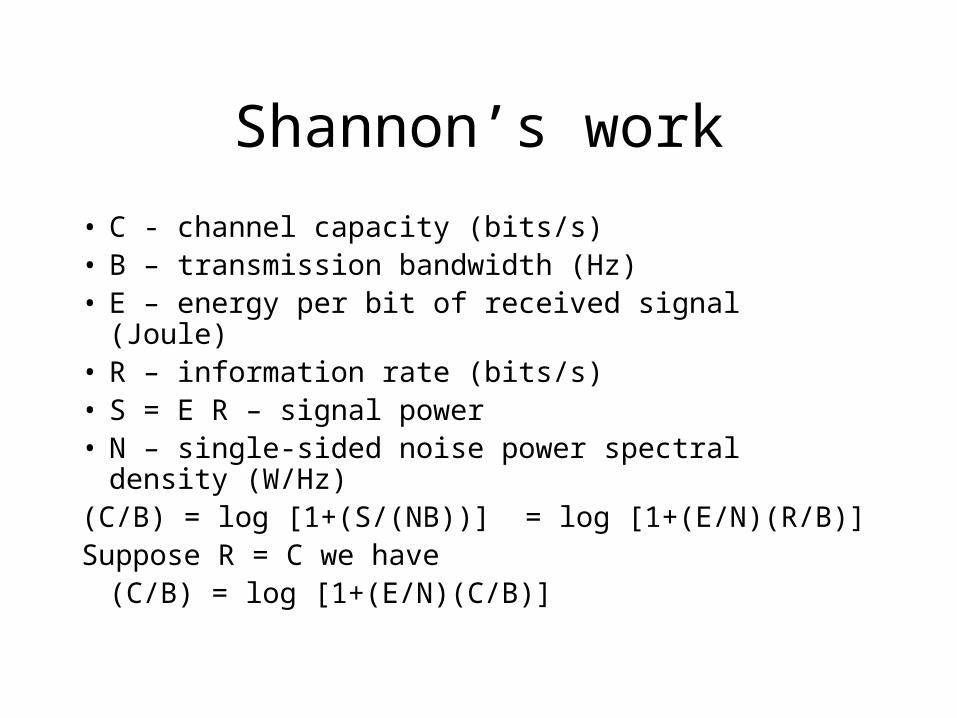
• C - channel capacity (bits/s)• B – transmission bandwidth (Hz)• E – energy per bit of received signal (Joule)• R – information rate (bits/s)• S = E R – signal power• N – single-sided noise power spectral density (W/Hz)(C/B) = log [1+(S/(NB))] = log [1+(E/N)(R/B)]Suppose R = C we have
(C/B) = log [1+(E/N)(C/B)]
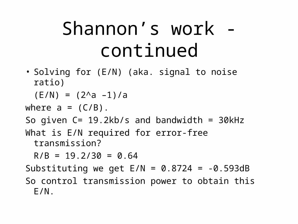
Shannon’s work - continued
• Solving for (E/N) (aka. signal to noise ratio)
(E/N) = (2^a –1)/a
where a = (C/B).
So given C= 19.2kb/s and bandwidth = 30kHz
What is E/N required for error-free transmission?
R/B = 19.2/30 = 0.64
Substituting we get E/N = 0.8724 = -0.593dB
So control transmission power to obtain this E/N.

Propagation models in built-up areas
• Propagation is strongly influenced by the environment
- building characteristics
- vegetation density
- terrain variation
• Perfect conductors reflect the wave where as nonconductors absorb some energy!
Empirical models to predict propagation losses
• Okumura’s model- based on free space path loss + correction
factors for suburban and rural areas, irregular terrain, street orientations
• Sakagmi and Kuboi model- extend Okumura’s model using regression
analysis of data.• Hata’s model
- empirical formula to describe Okumura’s data
More models
• Ibrahim and Parsons model
- equations developed to best fit data observed at London. (freq. 168-900 MHz)
• Lee’s model– Use at 900MHZ– 3 parameters (median trasmission loss, slope of
the path loss curve and adjustment factor)
Freq. for mobile communication
2.2.1
• VHF-/UHF-ranges for mobile radio– simple, small antenna
• SHF and higher for directed radio links, satellite communication– small antenna, focusing– large bandwidth available
• Wireless LANs use frequencies in UHF to SHF spectrum– limitations due to absorption by water and oxygen
• weather dependent fading, signal loss due to by heavy rainfall etc.

Modulation
• Digital modulation– digital data is translated into an analog signal – ASK, FSK, PSK (… Shift Keying)– differences in spectral efficiency, power efficiency,
robustness
• Analog modulation– shifts center frequency of baseband signal up to the
radio carrier
• Motivation– smaller antennas (e.g., /4)

Types of Modulation
• Amplitude modulation
• Frequency modulation
• Phase modulation
• Combination modulation

synchronizationdecision
digitaldataanalog
demodulation
radiocarrier
analogbasebandsignal
101101001 radio receiver
digitalmodulation
digitaldata analog
modulation
radiocarrier
analogbasebandsignal
101101001 radio transmitter
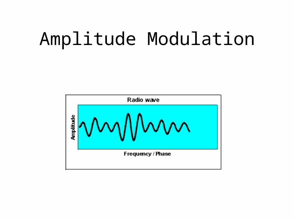
Amplitude Modulation
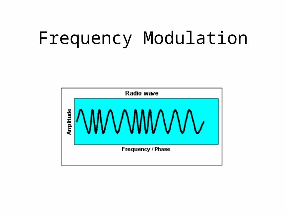
Frequency Modulation

Phase Modulation
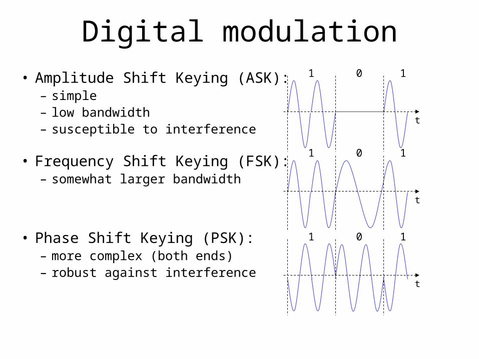
Digital modulation
• Amplitude Shift Keying (ASK):– simple– low bandwidth – susceptible to interference
• Frequency Shift Keying (FSK):– somewhat larger bandwidth
• Phase Shift Keying (PSK):– more complex (both ends)– robust against interference
1 0 1
t
1 0 1
t
1 0 1
t