Corsa Jul 2004
264
VAUXHALL Corsa & Combo Owner’s Manual
-
Upload
zorana-rakic -
Category
Documents
-
view
107 -
download
4
description
Opel Corsa user manual
Transcript of Corsa Jul 2004

VAUXHALL Corsa & Combo
Owner’s Manual

0
Data specific to your vehiclePlease enter your vehicle’s data here to keep it ea sily accessible.This information is available under the section "Technical da ta " as well as on the identification plate.
Fuel
Designation
Engine oil
Grad e
Viscosity
Tyre inflation pressure
Tyre size with up to 3 persons with full load
Sum mer tyres Front R ear Front R ea r
Winter tyres Front R ear Front R ea r
Weights
Permissible gross vehicle weig ht
– EC kerb weight
= Loading
Level control
Bump er H eig ht see page 92

1
Your CorsaDeveloped to the la test findings of vehic le research, it offers technical sophistication and exceptiona l comfort.
Your vehicle represents an ideal synthesis of ad vanced technolog y, outsta nding safety, environm ental compatibility and economy in opera tion.
It now lies with you to drive your vehicle safely and to see it performs perfectly.
This Owner's Manual provides you with all the necessary information to tha t end.
The Owner's Manual should a lways be kept in the vehicle: ready to hand in the g love com partment.
Make use of the Owner's Manual: z Its “In brief” section will give you an initial overview. z Its index will help you find what you want. z It will familiarize you with the sophisticated technology. z It will increase your pleasure in your vehicle. z It will help you to handle your vehicle expertly.
The Owner's Manual is designed to be clearly laid-out and easily understood.
This symb ol:6 signifies: continue reading on next page.
3 The asterisk sig nifies equipment op tions not in all vehicles (model variants, engine options, models specific to one country, op tional equipment, Genuine Vauxhall Parts and Accessories).
Yellow arrows in the illustrations serve as points of reference or ind icate some action to be performed.
Black arrow s in the illustrations indicate a reaction or a second ac tion to be perform ed.
We w ish you m any hours of pleasurable drivingYour Va uxhall team
Text highlighted in yellow in p artic ular indica tes possible risk of accident and injury. Disregard of these notes can lead to injuries which may b e fatal. Vehicle passengers must b e informed accordingly.

2

Contents
3
Comm itment to custom er satisfaction:Our aim: to keep you happy with your vehicle. All Vauxhall Authorised Repairers offer first class service at competitive prices. Experienced, factory-trained technicians w ork according to factory instructions.Your Authorised Repairer can supply you with GENUINE VAU XHALL-APPROVED PARTS, which have und ergone stringent quality and precision chec ks, and of course useful and a ttrac tive VAUXHALL-APPROVED ACCESSORIES.Our nam e i s your guara ntee!
For d eta ils of theVa uxhall Authorised Rep airer Netw orkplease r ing this number; 01582 - 427200
In Brief . ..... .... ..... .... .... ..... .... ..... .... ..... .... .... . 4Instrum ents ... ..... .... .... ..... .... ..... .... ..... .... .. 29Keys, doors, b onnet .. ..... .... ..... .... ..... .... .. 50Seats, Interior ..... .... .... ..... .... ..... .... ..... .... .. 64Safety system s ... .... .... ..... .... ..... .... ..... .... .. 78Lighting ..... .... ..... .... .... ..... .... ..... .... ..... .... .. 99Windows, sun roof,
folding top ..... .... .... ..... .... ..... .... ..... .... 103Clim ate c ontrol .. .... .... ..... .... ..... .... ..... .... 112Easytronic . .... ..... .... .... ..... .... ..... .... ..... .... 126Automatic transm ission 3 ..... .... ..... .... 132Driving hints . ..... .... .... ..... .... ..... .... ..... .... 138Saving fuel,
protecting the environment ... ..... .... 140Fuel consum ption,
fuel, refuelling ... .... ..... .... ..... .... ..... .... 142Catalytic converter, exhaust gases .... 144Drive Control Systems ... .... ..... .... ..... .... 148Brakes ... ..... .... ..... .... .... ..... .... ..... .... ..... .... 152Wheels, tyres . ..... .... .... ..... .... ..... .... ..... .... 156Roof racks, c aravan and trailer towing . ....
160Self-help .... .... ..... .... .... ..... .... ..... .... ..... .... 170If you ha ve a problem ... .... ..... .... ..... .... 208Maintenance,
inspection System . ..... .... ..... .... ..... .... 210Vehicle care .. ..... .... .... ..... .... ..... .... ..... .... 221Technical Data . .... .... ..... .... ..... .... ..... .... 226Index . .... ..... .... ..... .... .... ..... .... ..... .... ..... .... 254

4
In Brief
Key num bers, code numbers Remove key number from keys.
The key number is specified in the vehic le docum ents and in the Car Pass 3.
Alloy wheels 3, tow ing equip ment 3 : M ake a note of the key identifier cod es.
Elec tronic imm obiliser, infotainment system 3: The code numb ers are specified in the Ca r Pass.
Do not keep the Car Pass in the vehic le.
6 Further information – see pa ges 50, 51.
To unlock vehicle :Press button q 3, l ift door handleTo unlock using the key in the driver’s door lock: Turn key tow ards front of vehic le, lift door handle.
Locking from the inside: Press lock buttons.
6 Door locks, child safety locks 3 – pag e 50,electronic immobiliser – page 51,radio remote control 3 – page 52,central loc king system 3 – pag e 54,Vauxhall alarm system 3 – page 60.

5
To unlock luggage compartment:Turn key clockwise as faras it will go In order to avoid being locked out, the key cannot be removed.
Position of key slot in lock:– Horiz ontal Lug gage compartment
locked andunloc ked tog etherwith centrallocking system.
– Vertica l Lug gage compartmentis always locked.
Radio remote control 3 – page 52,central lock ing system 3 – page 54,Vauxhall alarm system 3 – page 60.
Seat adjustment 3:Pull handle, slide seat,release handle,allow seat to audibly latch into positionNever adjust the driver’s seat whilst d riv ing. It could move in an uncontrolled manner when the handle has been pulled.
6 Seat position – see page 64.
Adjusting seat backrest:Turn handwheel Move seat bac krest to suit sea ting position.
Do not lea n on seat back rest whilst adjusting it.
6 Sea t position – see pa ge 64.
Im porta nt : Do not sit nearer than 10 inches (25c m) from the steering wheel, to permit safe airbag dep loyment.
6
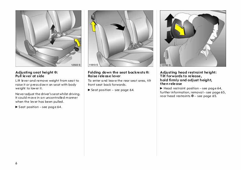
Adjusting seat height 3:Pull lever at s ide Lift lever and remove weight from sea t to raise it or p ress d ow n on seat with body weight to low er it.
Never adjust the driver’s seat whilst driving. It could m ove in a n uncontrolled m anner when the lever has been pulled .
6 Seat position – see pag e 64.
Folding down the seat backrests 3:Raise release lever To enter a nd leave the rear sea t area, tilt front seat back forwards.
6 Seat position – see page 64.
Adjusting head restraint height:Tilt forwards to re lease, hold firmly and adjust height,then release 6 Head restraint position – see pag e 64,further information, remova l – see page 65,rear head restra ints 3 – see page 65.

7
Adjusting interior m irror:Swivel mirror hous ing Swivel lever on underside of mirror housing to red uce daz zle a t nig ht.
Adjusting automatic anti-dazzleinterior mirror 3 :Swivel mirror housing Dazzle at night is automa tic ally red uc ed.
The mirror does not reduc e da zzle when:
z the ig nition is sw itc hed off,
z reverse gear is eng aged or selector lever set to R,
z interior lighting has been switched on.
8
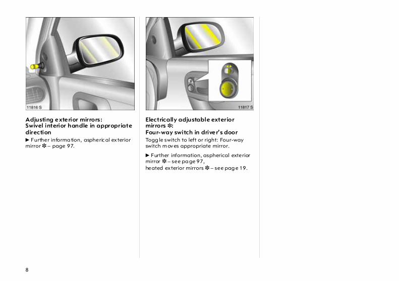
Adjusting exterior mirrors :Swivel interior handle in appropriate direction 6 Further informa tion, aspheric al exterior mirror 3 – page 97.
Electrically adjustable exterior mirrors 3: Four-way switch in driver’s door Togg le switch to left or right: Four-way switch m oves appropriate mirror.
6 Further information, aspherical exterior mirror 3 – see pa ge 97,heated exterior mirrors 3 – see pag e 19.

9
Fitting seat belt:Draw seat belt smoothly from inertia reel, guide over shoulderand engage in buckle The b elt must not be twisted at any point. The lap belt must lie snugly against the body. The backrest must not be tilted bac k too far (recomm ended tilting angle approx. 25°).
To release belt, press red button on belt buckle.
6 Safety belts – see pa ges 79 to 83,airbag systems 3 – see p age 84,seat p osition – see page 64.
Disengaging steering column lock:To re lease the lock, move the steering wheel slightlyand turn the key to position I Positions: o = Ignition offI = Steering released, ig nition offII = Ignition on,
with diesel engine: PreheatingIII = Start (transmission in neutral)
6 Starting – page 23,electronic im mobiliser – pa ge 51,Remove key and lock steering wheel– see page 24.
Steering wheel adjustment 3: Swivel lever down,adjust height,swivel lever up,engage Adjust steering wheel only when vehicle is stationary and steering colum n loc k is released.
6 Airbag systems – see pag e 84.

1010

11
Page1 Side air vents ... ..... .... ..... .... .... ..... ... 115
2 Front pa ssenger airbag 3 .... ..... .... . 84
3 Infotainm ent system 3 . .... .... ..... .... . 48
4 Haza rd warning lights .. .... .... ..... .... . 17LED for Vauxhall alarm system 3 ..60
5 Display 3 for tim e, date,outside tem perature,infotainment system 3 . .... .... ..... .... . 37
6 Centre air vents .... .... ..... .... .... ..... .... 115
7 Turn signal, headlight flash,dipped and main beam ... .... ..... .... . 15Door-to-door light function 3 ... .... ..... .... .... ..... .... . 16Cruise control 3 .... .... ..... .... .... ..... .... 150
8 Horn .... .... ..... .... ..... .... ..... .... .... ..... .... ..17
9 Infotainm ent system remote control 3 . ..... .... ..... .... ..... .... .... ..... .... . 26
10 Instruments .. .... ..... .... ..... .... .... ..... .... . 29
Pa ge11 Lever for w indscreen wiper
and wash system as well as headlight wash system 3 and rear window w ash system 3 .... ..... .. 17
12 Light switch ..... .... ..... .... .... ..... .... .15, 99
13 Head lig ht range adjustment 3 ..... 100Fog tail lig ht .... .... ..... .... .... ..... .... ..... 101Fog lights 3 ..... .... ..... .... .... ..... .... ..... 101Instrument illumination ... ..... .... ..... 101
14 Bonnet release lever . .... .... ..... .... ..... . 63
15 starter switchwith steering wheel lock .. ..... .... ..... ... 9
16 Steering wheel adjustm ent 3 ... ..... ... 9
17 Ac celera tor pedal .... .... .... ..... 138, 139
18 Brake peda l ..... .... ..... .... .... ..... 138, 153
19 Clutch ped al 3 .... ..... .... .... ..... .... .... 139
Page20 Heated seats 3 .. ..... .... ..... .... ..... .... 115
21 Accessory socket orcigarette lighter . ..... .... ..... .... ..... .... .. 75
22 Ashtray 3 .... .... .... ..... .... ..... .... ..... .... .. 76
23 Air conditioning system 3 ... ..... .... 114 Heated rear w indow 3 ... .... .... 19, 114
Air recirc ulation system 3 .... ..... .... 114
24 Heating and ventilation system .. 112Clim ate c ontrol system 3 .... ..... .... . 119
25 Glove compartment ... ..... .... ..... .... .. 77

12
Control indicators X Sea t belt 3:
see p age 29.
q Hea dlight range adjustm ent 3:see p age 100.
> Fog l ights 3: see p ages 29, 101.
A Engine electronics,immob iliser 3,automat ic tra nsm ission 3,Easyt ronic 3,fault:see p ages 29, 51, 146.
Z Exhaust em ission 3:see p ages 30, 51, 146.
v Airbag systems 3,bel t tensioners:see p ages 80, 89.
I Oil pressur e: see page 30.
O Turn signal l ights: see pages 16, 31.
C Main beam: see pages 15, 31.
! Prehea ting 3 for diesel engines see page 31.
1 Elec tronical ly controlled driv ingprog ramm es forautom atic transmission 3,sporty driv ing pr og ramm e: see page 134.
T Autom atic t ransmission 3,Easytronic 3,winter program me:see pages 128, 134.
r Fog tai l light:see pages 31, 101.
p Alternator: see page 31.
R Brake system,clutch system : see page 32.
u Anti-lock brake system 3: see page 154.
S Engine oil level 3: see pages 32, 212.
EPS Electr onic power steering 3: see page 32.
v Traction Control System (TCPlus) 3:Electr onic Sta bility Program(ESPPlus)3: see pag e 148.
g Trailer turn signa l 3:see page 32.
Y Fuel level: see pages 32, 36, 170.
y Seat occup ancy recog nition 3: see pages 89, 90.

13
LightingLig ht switch,stalk p osi tions: see p ages 15, 99,
7 Lights off,
8 Park ing lights,
9 Dip ped and main beam.
0 Courtesy lig ht:see p age 101.
C Main beam : see p age 15.
O Turn sig na l lights: see p age 16.
> Fog l ights 3: see p age 101.
r Fog tail lig ht:see p age 101.
k Instrument illum ination: see p age 101.
? Hea dlight range adjustm ent 3: see p age 100.
¨ Haza rd wa rning lig hts: see p age 17.
Clim ate control x Air flow:
see pages 113, 122.
Air distribut ion: see pages 113, 122,
V To windscreen andfront door wind ow s,
J To windscreen, frontdoor windowsand footwell,
K To footwell,
L To hea d area and footwell,
M To hea d area .
Ü Hea ted rear window 3 : see pages 114, 121.
n Air condi tioning system 3:see page 114.
4 Air recirculation system 3: see page 114.
AUTO Automa tic mod e 3: see page 120.
ECO AC com pressoractivation/deact ivat ion 3: see page 122.
ß Hea ted sea ts 3: see page 115.

14
Sun roof 3
l Sun roof op ening/lowering:see p age 106.
\ Sun roof closing/raising:see p age 106.
Folding sun roof 3\ Folding sun roof
op ening:see p ages 107, 109.
l Folding sun roof closing:see p ages 107, 109.
Windscreen wiper Stalk positions: see p age 17,
§ Off,
$ Interval operation orautomat ic wiperwith ra in sensor 3;
% Slow,
& Fast.
Date, time, information display,Infotainment system
Inform ation d isp lay 3: see page 37.
Ö On button for date and time,
; Setting buttons for date and time
Infotainment systemremote contr ol 3: see page 26.
Cruise control 3 Buttons on turn sig na l stalk:see page 150.
I Activate, store, a ccelerate
R Resumestored speed, decelerate
§ Deactivate.
Miscellaneous p Central locking system 3:
loc king – see pag e 54.
q Central locking system 3: unlocking – see page 54.
j Horn: see page 17.
T Winter program , automa tic tr ansm ission 3,Easytronic 3 : see pages 128, 134.
+ Fir st- aid kit (cushion) 3 : see page 174.
¨ Wa rning triangle 3: see page 174.

15
Light switches: 7 = Off 8 = Parking lights 9 = Dipped or m ain beam
Press 0 = Courtesy lig ht
Press > = Fog lights 3
Press r = Fog tail light
6 Further informa tion – page 99,head lig ht warning device – page 24,head lig ht ra nge adjustment 3 – pa ge 100,daytim e running lights – page 99.
Dipped and main beam switch:Main beam = Push lever forwardDipped beam = Push lever forward
again Blue control ind ic ator C is lit when main beam is activated .
Headlight flash:Pull stalk towards steering wheel

16
To activate door-to-door light function: Key to o and remove,open driver’s door,pull turn signal stalk tow ard steering wheelThe d ip ped beam remains on for a further 30 second s a fter closing the driver’s door.
If the driver’s door is left open, the lights will go out after tw o minutes.
Door-to-door lighting can be deactivated by inserting the key in the starter switch or by pulling the turn signal stalk toward the steering wheel again.
Operating turn signal lights :Lever in rest pos itionright = upleft = downWhen the steering wheel is turned bac k, the lever automatically returns to its orig inal position. This will not happen when mak ing a minor steering m anoeuvre such as cha ng ing lane.
When lane changing, m ove lever to resistance point. When released, the lever will spring b ack.
To operate cruise control 3 :Press buttons on stalk Switc h on: tap button I.
Switc h off: tap button §.
Resume at stored speed: tap button R.
6 Cruise control 3 – see p age 150.

17
Hazard warning lights:On = Press ¨Off = Press ¨ againTo aid location of the pushbutton, the red surface is illum ina ted when the ignition switched on. When the button is p ressed, its c ontrol ind ic ator flashes in time with the hazard warning lig hts.
Horn operation: Press j 6 Airbag systems 3 – pa ge 84, remote control for radio and Infota inm ent system 3 – see pag e 26.
Windscreen wiper:Stalk up § = Off $ = Adjustable interval % = Slow & = Fast Setting wiper interva l to a va lue between 2 and 15 seconds:
Stalk to interval switching $,Stalk to §,Wa it for d esired interval,Stalk b ack to interval sw itc hing $.
The interval remains stored until the next change or until the ig nition is switched off. Switc hing the ignition off and m oving the stalk to $ sets the interval to 7 seconds.

18
Autom atic w iper with rain sensor 3:Move lever up § = Off $ = Automatic wiper
with rain sensor % = Slow (constant) & = Fast (constant) Autom atic wiping $ : The rain sensor detects the a mount of wa ter on the windscreen and automatically regulates the w indscreen wiper.
Push lever down to sw itch off.
If necessary, the positions % or & can be selected m anually .
Operating windscreen and headlight wash systems 3:Pull stalk towards steering wheel The wiper will swipe for a few strokes.
The head lig ht wash system 3 ca n be op erated when the lights are on.
On vehicles fitted w ith ra in sensor 3, keep the sensor area c lean.
6 Further information – see p ages 218, 224.
Operating rear window wiper and wash system s 3: Wiper on = Push lever forwardWiper off = Pull lever towards
steering wheelwash = Push lever forward
and hold The rear window w iper swipes in timed interva l mode.
The wip er will swip e for a few strokes when washing.
6 Further inform ation – see pages 218, 224.

19
Heated rear window 3,heated exterior mirrors 3:On = Press ÜOff = Press Ü again Rear window and exterior m irror heating with ignition sw itched on. Control indicator in switch.
6 Further inform ation – see pages 114, 121.
Clearing misted or icy window s:Turn rotary switches for temperature and air flow clockwise,set air distribution to V,press air conditioning switch n 3 Close centre air vents; p ush sliders inw ards. Direct side air vents towards d oor windows.
6 Clim ate control – see pa ge 112,air conditioning system 3 – see pa ge 114,electronic air conditioning system 3 – see p age 119.
To set autom atic m ode ofautomatic climate control system 3:Press AUTO button,set tem peratureusing rotary knob Open a ll air vents.
6 Electronic air c onditioning system 3 – see pag e 119.

20
Inform ation display 3:Display of information – Tim e,– Outside temperature,– Radio 3 or da te,– Navigation 3,– Telephone 3,– Trip computer 3 .
6 Information Display – see page 37.
Manual transmiss ion: Reverse gear: With vehicle stationary , pull the ring up three seconds after de-clutching and eng age gear.
If the gear does not engage: With lever in neutra l, briefly release clutch pedal and depress again, then repeat gear selection.
Easytronic 3:N = Neutral/Start position o = Centre pos ition
(Drive position) + = Higher gear - = Low er gearA/M = Change between
Automatic andManual mode
Only start in N with foot brake applied.
6 Further inform ation – page 126.

21
Easytronic 3:R = Reverse
(with selector lever lock) To move the selector lever from N to R press the b utton on the lever.
6 Further inform ation – page 126.
Automatic transmiss ion 3:P = Park
(with selector lever lock)R = ReverseN = Neutral Only start in P or N , to leave P switch ignition on, app ly foot brake and pull ha ndle beneath selector lever.
To engage P or R pull release under selector lever.
P: Only w ith vehicle stationary, first apply hand brake
R: Only w ith vehicle stationary
6 Autom atic transmission – see page 132.
Automatic transmission 3:D = 1st to 4th gear3 = 1st to 3rd gear2 = 1st and 2nd gear1 = 1st gearalsoS = sporty driving programm e Selec t 3, 2 or 1 if c ertain gears a re not desired, e.g. 4-3-4 . . . on winding roads, or in order to utiliz e the engine braking effect when driving downhill.
To select 3 or 1 pull ha ndle beneath selector lever.
6 Automatic transmission – see pa ge 132.

22
Autom atic transmission 3:Protection against unintentional engagem ent of P, R, 3 or 1 Pull relea se under selector lever 1, P: U p to final stop.
When selecting any p osition from 1 to N or from R to D d o not pull handle beneath selector lever.
6 Automatic transmission – see page 132.
Exhaust gases are poisonous Exhaust gases contain carbon monoxide, whic h is extrem ely poisonous b ut is od ourless and colourless.
Therefore never inhale exhaust gases, and never run the engine in an enc losed space.
Also avoid driving with the lugga ge compartment op en. Otherwise exhaust fumes could penetrate the vehicle interior.
Before starting off, check: z Tyre pressure and condition –
see pages 157, 243.
z Engine oil level a nd fluid levels in engine compartment – see pages 211 to 218.
z All windows, mirrors, exterior lig hting and number plates are free from dirt, snow and ice a nd operational.
z Do not place any objec ts in front of the rear window, on the instrument panel or in the area in which the a irba gs inflate.
z Seats, seat belts and mirrors are correctly a djusted .
z Check brakes.
23
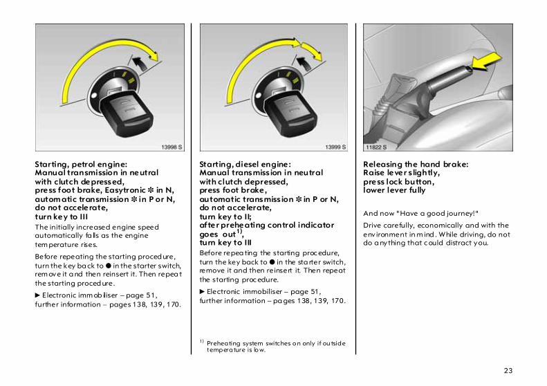
Starting, petrol engine:Manual transmission in neutralwith clutch depressed,press foot brake, Easytronic 3 in N,autom atic transmission 3 in P or N,do not accelerate,turn key to III The initially increased engine speed automatically fa lls as the engine tem perature rises.
Before repeating the starting proced ure, turn the key ba ck to o in the starter switch, rem ove it a nd then reinsert it. Then repea t the starting proced ure.
6 E lectronic imm ob iliser – page 51,further information – pages 138, 139, 170.
Starting, diesel engine: Manual transmiss ion in neutralwith clutch depressed,press foot brake,automatic transmiss ion 3 in P or N,do not accelerate,turn key to II;after preheating control indicatorgoes out1),turn key to III Before repea ting the starting proc edure, turn the key back to o in the sta rter switch, remove it and then reinsert it. Then repeat the starting proc edure.
6 Electronic immobiliser – page 51,further information – pa ges 138, 139, 170.
Releasing the hand brake:Raise lever s lightly,press lock button,lower lever fully
And now "Have a good journey!"
Drive carefully, economically and with the env ironment in m ind . While driving, do not do a nything that c ould distract you.
1) Preheating system switches o n only if ou tside temperature is lo w.

24
Warning buzzers While driving: z If seat belt is not fastened 3,
z If a specified maximum speed is exceed ed 3.
When the vehicle is parked and the d river’s door is opened: z When the ignition key is in the starter
switch,
z If parking lights or d ipped beam are on,
z If the turn signal stalk is engaged.
Parking the vehicle:Apply handbrake firm ly,engine off,rem ove key,lock steering wheel,lock doors To lock , press button p or turn key in lock tow ards rear of vehicle. To activate anti-theft lock ing system 3 and Vauxhall alarm system 3, press button p twice.
6 Further information – p ages 51, 138,ra dio remote control 3 – page 52,central locking system 3 – page 54,Vauxhall a la rm system 3 – p age 60.
Advice when parking: z Alw ays apply hand brake firmly. On
slopes app ly the hand brake a s firmly as possible.
z With m anual transmission, engage first gear or reverse gear. With Easytronic 3, place selector lever in mid position before switching off ignition. With autom atic transmission 3 , p la ce selector lever in P.
z Close window, sun roof 3 and folding top 3.
z On vehicles with Easytronic 3 the control ind ic ator R fla shes for a few seconds after the ignition is switched off if the ha nd brake has not b een applied .
z In vehicles with autom atic tra nsmission 3 the key ca n only be removed when the selector lever is in P.
z Turn steering wheel until lock is felt to engage (anti-theft protection).
z Engine cooling fan m ay run on after the engine has been switched off.
z Do not park vehicle on easily ignitable surfaces as the hot exhaust system temperatures could cause the surfa ce to ignite.

25
Service work,Maintenance We recomm end tha t you entrust all w ork to your Vauxhall Authorised R epairer, who can provide you w ith reliable service and correctly perform all work according to factory instructions.
6 Vauxhall Service – page 208,service interval display – page 210.
Genuine Vauxha ll Parts and Accessories We rec om mend that you use "Genuine Vauxhall Parts and Accessories" a nd conversion p arts released expressly for your vehicle type. These parts ha ve undergone spec ia l tests to establish their reliability, safety a nd specific suitability for Vauxhall vehicles. Despite continuous market monitoring, we ca nnot assess or guarantee these attributes for other prod uc ts, even if they have b een granted approval by the releva nt authorities or in some other form.
"Genuine Vauxhall Parts and Accessories" and conversion parts approved by Vauxhall c an be ob tained from your Vauxhall Authorised Repairer, of c ourse. Here you will also be given comprehensive advice about permitted technical changes and correct installation w ill take place.
That was a brief lookat the most importantinform ation for your f irst drive inyour Corsa/Combo.
The other pagesof this chaptercontain a description of some interesting functionsin your vehicle .
The rem aining chaptersof the Owner’s Manualcontain important informationon operation, safetyand maintenanceas well as a fullindex.
For your safety Carry out regularly the checks rec om mended in the indiv idual sections of this Owner’s M anual.
Ensure that your vehicle is serv iced as specified in the Service Booklet. We rec om mend that you consult your Vauxhall Authorised R epairer.
Have faults remedied without d elay! Consult a workshop. We recommend your Vauxhall Authorised Repairer. If necessary , interrupt your journey.
6 Maintenance – see page 210.

26
Infotainm ent system operation Functions are selected and executed in the menu on the display using the four-way button, the m ultifunction b utton 3 on the Infotainm ent system or the buttons 3 on the steering wheel. Corresp onding m enu options are shown on the display.
Selecting with four-way button: Press four-way button up, down, right or left.
Selecting with multifunction button: Press and turn multifunction button.
To exit a menu, turn m ultifunc tion button left or right to Return or Main and select.
Selec ting with steering wheel buttons: Selec t menu options via the menus using the buttons.
For further information, see Infotainm ent system instructions.

27
Trip computer 3 The trip com puter shows vehicle data tha t is continually recorded and evaluated electronic ally .
Functions:z Rang ez Instantaneous consumptionz Distancez Average speedz Trip consumptionz Average consump tionz Stop watch
Vauxhall Full Size airbag system The Vauxhall Full S ize a irb ag system comprises severa l ind ividual systems.
Front a irbag system The front airb ag system is triggered in the event of a serious accident involving a frontal impa ct and forms sa fety cushions for the driver and front passenger. The forward movement of the driver a nd front passenger is checked a nd the risk of injuries to the up per body and head thereby substantially reduced.
Side airba g system 3 The side airbag system triggers when a side-on collision occurs and provides a safety barrier for the driver a nd/or passenger in the respective front door area. This reduces the risk of injury to the upper body considera bly in case of a side impa ct.
Cur tain ai rbag system 3 The curtain a irba g system triggers in case of a side-on collision and provid es a safety barrier in the hea d area on the respective side of the vehic le. This reduces the risk of injury to the hea d considerab ly in case of a side-on collision.
6 Further inform ation – page 84.

28
Active head restraints 3 In the event of a rear-end impa ct, the active head restraints automatically tilt forward a little. The head is more effectively supported by the head restraint and the danger of injuries caused by whiplash in the a rea of the neck is reduced.
Active head restraints can be identified by the lettering ACTIVE on the head restraint guide bushes.
Parking distance sensor 3 The parking dista nce sensor automatically switches itself on when reversing.
If the vehicle a pproaches an obstacle w hen reversing, a series of signals c an be heard in the vehicle interior. The interval betw een the signa ls b ecomes shorter as the distance is reduced. If the distanc e is less than 30 cm, the signal will be continuous.
6 Further information – page 151.
ECOService-Flex The oil cha nge and service intervals are flex ible, based on a num ber of different param eters and the conditions under which the vehicle is used. Various eng ine-spec ific d ata is continuously recorded and used to c alcula te the remaining distance until the next service is due.
To display remaining distance:
z Ignition off.
z Press reset button below speedometer.
z InsP and the remaining distance a re displa yed.

29
Instruments
Control indicators The c ontrol indicators described here are not present in all vehicles. The description applies to all instrument versions.
X Seat belt 3 Warning light lights up (accompanied by an acoustic w arning) when ignition is switched on: Fasten your seat belt – see page 81.
? Automat ic head light range adjustment 3 Lit: Fault in system. Contact a w orkshop immed iately. We recommend your Vauxhall Authorised Repairer. See page 100.
> Fog l ights 3 Control indica tor lights up when fog lights are switched on.
A Engine elect ronics, transmission electronics, imm obiliser, d iesel fuel fi lter 3 Control indicator lights up for a few seconds when engine is switched on.
Lights w hen the engine is runningFault in engine electronics or transm ission electronics. Electronics switch to emergency running programme. Fuel consum ption may increase and driveability of the vehicle may be impaired – see pag e 146. Contact a w orkshop. We recommend your Vauxhall Authorised Repairer.
If it flashes when the ignition is onFault in the electronic immobiliser system ; the engine c annot be started – see pag e 51.

30
Z Exhaust emission Control indicator lights up when ignition is switched on and goes out shortly after engine sta rts.
Lights when the eng ine is runningFault in emission control system. The permitted emission limits may be exceeded. Consult a workshop . We recom mend your Vauxhall Authorised Repairer.
If it flashes when the engine is runningFor fault that can lead to destruction of the catalytic converter, see page 146. Consult a w orkshop imm ediately. We recomm end that you consult your Vauxhall Authorised Repairer.
v Airbag systems 3,belt tensioners see p ages 81, 89.
I Oil p ressure Control indica tor lights up when ignition is switched on and goes out shortly after engine starts. Ca n lig ht up intermittently when idling with hot engine; must go out when engine speed is increased.
Lights w hen the engine is runningEng ine lubrication m ay be interrup ted. This ma y result in damage to the eng ine and/or locking of the drive wheels:
1. Depress clutch.
2. Move gear shift lever to neutral; with autom atic transmission 3 and Easytronic 3 m ove selector lever to N .
3. Move out of the flow of traffic a s quickly as possible without impeding other vehicles.
4. Switching the ignition off (Position I ).
Consult a workshop . We recommend your Vauxhall Authorised Repairer.
When the ignition is off, c onsiderab ly more force is needed to brake and steer.
Do not remove key until vehicle has come to a stand still, otherwise the steering column lock c ould engage unexpectedly .
31
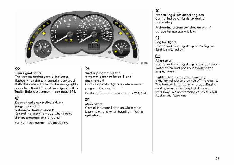
O Turn signal l ights The c orresponding control indicator flashes when the turn signal is activated. Both flash when the hazard warning lights are active. Rapid flash: A turn signal bulb is faulty. Bulb replacement – see page 194.
1 Elec tronically contr ol led driv ing prog ramm es for autom atic transmission 3 Control indicator lights up when sporty driving program me is enabled.
Further information – see pa ge 134.
T Winter program me forautomat ic tra nsm ission 3 and Easytronic 3 Control indica tor lights up when winter prog ra m is enabled.
Further inform ation – see pages 128, 134.
C Main beam Control indica tor lights up when main beam is on and when headlight flash is op erated.
! Prehea ting 3 for diesel engines Control indicator lights up during preheating.
Preheating system switches on only if outside temperature is low.
r Fog tai l lights Control indicator lights up when fog tail light is switc hed on.
p Alterna tor Control indicator lights up when ignition is switched on a nd goes out shortly a fter eng ine starts.
Lights w hen the engine is runningStop the vehicle and switch off the engine. The battery is not being charged. Eng ine cooling may be interrupted. Contact a workshop. We recommend your Vauxhall Authorised Repa irer.

32
R Brake system ,clutc h system The c ontrol indicator lights w hen the ignition is switched on if the hand brake is applied or if the brake or clutch fluid level is too low. Further informa tion – see pages 154, 216.
On vehicles w ith Easytronic 3 control indicator R flashes for a few sec onds after the ig nition is switched off if the hand brake has not been applied.
u Anti-lock brake system 3 see p age 154.
S Engine oil level 3 Lit: Eng ine oil level is too low. Check engine oil level and top up if necessary. See page 212.
EPS1) Electric power steering 3 The control indica tor lig hts up for a few second s w hen the ignition is switched on. Illum ination while driving ind icates a fault. Driv ing may be continued. More force is required for steering. Consult a workshop . We rec om mend your Vauxhall Authorised Repairer.
If lit when hand brake is not applied: Stop the vehicle; interrupt your journey im med ia tely. Consult a workshop. We recommend your Vauxhall Authorised Repairer.
1) EPS = Electric P ower Steerin g.
v Trac tion Control System (TC Plus) 3,Electronic S tabil ity Prog ram (ESPPlus) 3 see pages 148, 149.
g Trai ler turn signal 3 When tow ing a trailer or caravan, indicator light fla shes at sa me speed as turn signals. Does not flash if tra iler or towing vehicle turn signal fa ils.
Y Fuel level 3 Lit: Low fuel level. Fuel gauge in reserve area.
Flashing: Fuel supply used up, fill tank imm ediately.
Never let the tank run dry!
Petrol engines: Erratic fuel supp ly can cause catalytic converter to overheat. See pag e 144.
Diesel engines: I f the tank is run dry, bleed the fuel system as desc rib ed on pag e 170.

33
y Seat oc cupancy recognition 3 see pages 84, 89.
Transmission display 3 Display of selector lever position for autom atic transmission 3 or current gea r or mode for Easytronic 3.
Further inform ation – see pages 126, 132.

34
Tachometer
Indicates engine speed.
Warning zone: M aximum p ermissible engine sp eed exceeded ; danger to engine.
Speedometer Indicates the vehicle speed .
Odometer Records the k ilom etres driven.
Trip odometer To return to zero, depress reset knob with ignition switched on and trip odometer display activated .
Vehicles with clock in odometerTo set to z ero, hold reset knob down for app rox . 2 seconds with ignition switched on and trip od om eter activated .
To switch between trip od om eter and clock display 3 give reset knob a brief p ress – see next page.
Service interval d isplay , see page 210.

35
Time display in odometer 3 To sw itc h b etween trip odometer and time display 3 give reset knob a short press.
When the vehicle lights are on, the brightness of the display ca n be adjusted using the right-hand adjuster wheel k below the light switch – see pa ge 101.
Setting the t ime With time displayed, press reset knob in instrument:
Press for approx . 2 seconds, Hours flash,
Press briefly ,Set hours,
Press for approx . 2 seconds,Minutes flash,
Press briefly ,Set minutes,
Press for approx . 2 seconds,Clock is started .
36
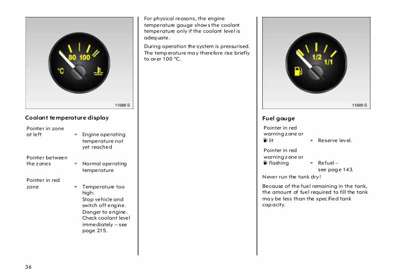
Coolant temperature display
For physical reasons, the engine temperature gauge show s the coolant temperature only if the coolant level is adeq uate.
During operation the system is pressurised. The temp erature ma y therefore rise briefly to over 100 °C.
Fuel gauge
Never run the tank dry !
Because of the fuel remaining in the tank, the amount of fuel required to fill the tank ma y be less than the spec ified tank cap acity.
Pointer in zone at left = Engine operating
temperature not yet reached
Pointer between the z ones = Normal operating
temperature
Pointer in red zone = Temperature too
high:Stop vehicle and switch off eng ine. Danger to engine. Check coolant level immediately – see page 215.
Pointer in red warning z one or Y lit = Reserve level.
Pointer in red warning z one or Y flashing = Refuel –
see pag e 143.

37
Inform ation display Triple inform ation d isp lay 3 Display of time, outside tempera ture and date/Infotainment system is switched on.
When the ignition is off, the time, date and outside tem perature can be made to appear for approx. 15 seconds by briefly pressing one of the two buttons adjacent to the d isplay .
Graphica l Informa tion Display 3 Display of time, outside temp erature a nd date/Infotainment system is switched on.
The information that is d isplayed depend s on the Infota inm ent system c onfiguration.
Fault d isplay --.-° C or F on the display ind icates a fault. Have the cause of the fa ult remedied. We recommend that you consult your Vauxhall Authorised Repa irer.

38
Triple inform ation display Setting tim e a nd dateInfotainm ent system off. Press Ö and ; next to the display as follows:
Correcting time 3 Some RDS tra nsmitters do not send correct tim e signals. If the incorrect time is displayed often, deactivate the automatic tim e synchronisation 3 a nd set the tim e manually.
The automatic setting is indicated by Ö in the display.
Correcting using RDS:Infotainment system off. Press Ö a nd ; next to the display as follows:
Graphical inform ation display 3,se lecting functionsThe functions a nd setting s of some equipment 3 can be accessed via the graphical information display.
Functions are selected and executed in the menu on the display using the four-way button, the multifunction button 3 on the infota inm ent system or the buttons 3 on the steering wheel.
Press Ö for ap prox . 2 seconds: Day fla shes
;: Set day
Ö : Month fla shes ;: Set month
Ö : Year flashes;: Set year
Ö : Hours flash;: Set hours
Ö : Minutes flash ;: Set minutes
Ö : Clock is started.
Hold down Ö for approx. 2 sec., c lock display is now in setting mode,
Press Ö twice (until year flashes),
Press Ö and hold down for ap prox . 3 seconds until } flashes in display a nd text "RDS TIM E" a ppears (years fla sh during this time),
Press ; ; Display ofRDS TIME 0 = Off.
Press ; ; Display ofRDS TIME 1 = On
Press Ö three times.

39
Selecting with four-way button:
Select menu options v ia the m enus using the b uttons or the four-way button on the infotainment system.
Selecting with multifunction button 3:
Turn Mark menu options,functions or comma nds,
Press Select marked item orconfirm comma nd.
To exit a menu, turn the multifunction button left or rig ht to Return or Main and select.
Selec ting with steering wheel buttons 3 :
Selec t menu options via the menus using the buttons.
6

40
Some displays and menus ca n b e selected by selecting the function in the top row of the d isplay :
z Audio z Navigation 3 z Telephone 3 z Trip computer 3
For audio, navigation 3 and telephone func tions 3, see Infotainment system instructions.
System setting s Settings are made in the S et tings menu.
Press Ma in button 3 (not found on all Infotainment systems) on Infotainment system (call up m ain displa y).
Press S ett ings button on Infotainment system.
The Setting s menu will b e displayed.
Sett ing tim e a nd dateSelec t menu item Time, Da te from the Sett ings menu.
The Time, Date menu will be disp layed .
Selec t the menu items required.
Make the desired setting .

41
Correcting time 3 On systems with GPS rec eiver1), tim e a nd date are a utoma tica lly set upon receipt of a GPS satellite sig nal. If the displayed time does not correspond to local time, time can be manually corrected in 30-minute increments or automa tica lly corrected via receipt of an RDS time signal2) 3.
Some RDS transm itters do not send c orrect time sig nals. I f the incorrect time is displayed often, deactivate the a utomatic time synchronisation 3 and set the time manually.
The a utomatic setting is indicated by Ö in the d isplay .
To correct with the help of R DS, select Synchron. clock autom atica l. from the Time, Date menu.
The fie ld for Synchron. clock a utomat ical. is ticked .
Lang uage selectionYou can select the d isplay language for some func tions.
Select menu item Lang ua ge from the Settings m enu.
The ava ilab le languages are d isplayed.
Selec t the desired language.
Selec tions are indic ated b y a 6 in front of the menu item.
On system s with language version 3, upon change of the language setting for the display, you will be asked if the m essag e language is also to be c hanged. See Infotainment system instructions.
1) GPS = G lo bal P o sitioning Sys tem,Satellite system for w orld-w ide positioning.
2) RDS = Radio Data Sys tem .

42
Setting units of measureYou ca n select w hich units of measure a re to be used.
Select menu item Units from the Settings menu.
The a vailable units are disp la yed .
Select the desired unit.
Selections are indicated by a o in front of the m enu item .
Adjust contra st 3 Select menu item Contrast from the Settings m enu.
The Contrast menu will be displa yed.
Confirm the required setting.
Sett ing display m ode 3 The display can be ada pted to lig ht conditions: black text on a light bac kground or white text on a da rk bac kground.
In m enu item Da y/Nig ht from the Sett ings menu.

43
The a lternatives are displayed.
Autom atic: adapted based on vehicle lighting .
Alw ays da y design: black text on light background.
Alw ays night design: white text on da rk background.
Selections are indicated by a o in front of the m enu item .
Ig ni tion logic 3 See Infotainment system instructions.
Graphical information display, trip com puter 3 The trip computer shows vehicle data that is continually rec orded and eva luated electronically.
There a re two trip c om puters which independ ently gather and evaluate d ata.
To display trip computer driving data, press the BC button on the infotainment system 3 or select the Board computer function via the display.
The Board com puter menu opens and range a nd insta ntaneous consumption a re displayed.
Som e functions are listed in the display in abb reviated form.

44
RangeRange is calculated based on the current amount of fuel in the tank and instantaneous consumption. Average values a re displayed.
After refuelling, the vehicle upd ates range automatically after a b rief delay.
If the tank only holds fuel sufficient for less than 30 miles (50 km), the message "Range" appears on the display.
Instantaneous consumption Information is displayed differently depending on sp eed :
Display in gal/h below 8 mp h (13 km /h)
Display in mpg above 8 mph (13 km/h)
Distanc e Shows the numb er of kilometres travelled. The measurement can be re-started at any time. See next column.
Avera ge sp eed Calcula tion of average speed. The measurement c an be re-started at any time. See next column.
Stopp ages in the journey with the ignition off are not included in the c alcula tions.
Trip consum ption Shows amount of fuel consum ed. The measurement c an be re-started at any time. See next column.
Avera ge consum ption Calcula tion of average consump tion. The measurement c an be re-started at any time. See next column.

45
Resetting trip comp uterinforma tion The following trip computer information can be reset (re-start of mea surem ent):
z Trip consumptionz Average consump tionz Average speedz Distance
Select BC1 or BC2 from the Board comp uter menu.
Select the desired trip computer information.
The value of the selected function is reset and a new value will be obtained.
To reset all information of a trip computer, select menu item Al l values.
Upon reset, "- - -" will b e shown for the selected trip computer information. The new ly obtained va lue will be shown a fter a brief delay .

46
Stop watchSelect menu item Timer from the Board com puter menu.
The Tim er menu w ill be d isplayed.
Select menu item Sta rt to start.
Select menu item Reset to reset.
Stop watch settings can be ma de v ia the Opt ions 3 menu:
Tr avel tim e without stop pages Measurement of the am ount of time the vehicle is in motion. Stoppages are not included.
Tr avel tim e with stop pages Measurement of the am ount of time the vehicle is in motion. Stoppages where the key rema ins in the ignition are includ ed.
Trip time Measurement of the time from manual activa tion via S tart to ma nual deac tivation via Reset.

47
Outs ide temperature A fall in temperature is indica ted immediately and a rise in temp erature after a time delay .
If outside tempera ture drops below 3 °C, the sym bol : appears in the triple inform ation d isplay as a warning for icy road conditions. When temperature increases to at least 5 °C, the : symbol goes out.
In vehicles with graphical inform ation display 3, a warning message appears on the display to warn of icy road c onditions. No message is disp la yed below -5 °C.
Caution: The road surface may already be icy even though the display indicates a few deg rees ab ove 0 °C.

48
Radio reception 3 Ca r radio reception differs from domestic radio reception:
As the vehicle aeria l is relatively near the ground, the broadcasting compa nies cannot g uarantee the sa me quality of reception a s is obtained with a domestic ra dio using an overhead aerial.
z Changes in distance from the transm itter,
z multi-path rec eption due to reflection and
z sha dowing may c ause hissing , noise, distortion or loss of reception a ltogether.
Infotainment system 3 The Infotainm ent system is operated as described in the operating instructions supplied.
Electronic data acquisition in toll system sOn vehicles with heat-reflecting windscreens1) 3, mount the chipcard for electronic data a cquisition and billing in the black shaded zone of the windsc reen on the left or the right behind the interior mirror, see illustration. If the chipcard is mounted outside this zone, there may be ma lfunctions in da ta acquisition.
1) Solar Reflect.

49
Mobile te lephones and radio equipment (CB) 3 The Vauxhall installa tion instructions and the operating guidelines p rov id ed by the telephone manufa cturer m ust be observed when fitting and operating a m ob ile telephone. Failure to d o so could invalida te the vehicle’s operating perm it (EU Directive 95/54/EG).
Prerequisites for fault-free op eration:
z Professionally installed exterior aerial to ob ta in the maximum range possible,
z Maximum transmission power 10 Watt,
z Installation of the telephone in a suitab le spot (see note on pag e 92).
Obtain ad vice on p redetermined installation loc ations for the external antenna and equipment holder and ways of using dev ices w ith transmission power of more than 10 Wa tts. We recom mend that you consult your Vauxhall Authorised Repairer, who will have brackets and various installation k its available as accessories and will install them in accordance with regulations.
Be sure to use the handsfree attachment if using the telephone w hilst driving. Even this can be a distraction while driving. Please ob serve country-spec ific regulations.
When used in the vehicle interior, mobile telephones and radio equipment (CB) with integrated aerial may cause malfunctions in the vehicle electronics.
Mobile telephones and radio equipm ent (CB) should only be used with an aerial fitted on the vehicle exterior.

50
Keys, doors, bonnet Replacement keys The key is a c onstituent of the electronic immobiliser. Ordering keys from a Vauxhall Authorised Repairer g uarantees problem -free op eration of the electronic immobiliser.
Keep the sp are key accessible in a safe place.
Locks – see page 224.
Locking / Unlocking From outside Radio rem ote control 3 – see p age 52,Central lock ing system 3 – see page 54,Mechanical operation – see pages 4, 56.
From inside Push down or pull up lock button. To prevent the driver from being inad vertently locked out, the button on the driver’s door cannot b e depressed when the d oor is op en.
Child safety locks 3
Turn rota ry knob at rear door lock from vertical position using key: Door cannot be opened from the inside.
Use the child safety lock whenever child ren a re oc cup ying on the rear seats. Disregard may lea d to injuries or endanger life. Vehicle p assengers should be informed accordingly.

51
Electronic imm obiliser The system checks whether the vehicle m ay be sta rted using the key that has been inserted. If the key is recognised as "authorised" the vehicle can be started. The c heck is carried out via a transponder housed in the key – see page 53.
The electronic immobiliser is automatically activated when the key is removed from the ig nition switch.
Control ind icator for imm obiliser A Control indicator A lights up briefly when the ignition is switched on.
If the control indicator flashes w hen the ignition is on, there is a fault in the system. The engine cannot be started.
1. Remove key .
2. Reinsert key in ignition switch.
3. Then repeat starting procedure.
If control indicator A continues to flash, try to start the eng ine using the spare key and consult a workshop. We recomm end your Vauxhall Authorised Repairer.
If c ontrol indicator A lig hts up after the eng ine has started, there is a fault in the eng ine electronic s or the automatic transmission – see pages 136, 146.
Note The immobiliser does not lock the doors. Therefore, alwa ys lock vehicle before leaving unattended and ena ble Vauxhall alarm system 3 – see page 60.
The Car Pass contains all of the vehicle’s data and should therefore not be kept in the vehicle.
Have your Car Pass on hand when consulting a Vauxhall Authorised Repa irer.

52
Radio rem ote control 3 The rad io remote control is integrated in the key.
Used to op erate:z central locking system, z mechanical anti-theft locking system 3, z Vauxhall ala rm system 3 .
The rad io remote control has a ra nge of approx. 3 metres. This range can be affected by outside influenc es. Aim the rem ote control at the vehicle to operate.
Handle the rad io remote control with ca re, protect from moisture and high temperatures and avoid unnecessary op eration.
The hazard warning lig hts come on to indica te that the remote control is op erational.
Central loc king system , see p age 54.
Va uxhall alarm system 3, see p age 60.
Fault If the central locking system cannot be operated w ith the radio remote control, it ma y be due to the following :
z The range of the radio remote control ha s b een exc eeded.
z Remote control battery voltage is too low . Battery rep la cement – see next page.
z Frequent, repeated operation of the radio rem ote control outside the reception ra nge of the vehicle (e.g. too far from vehicle, remote c ontrol is then no longer recognised). Remote control synchronisation –see next page.
z Overload of the central locking system by operating at freq uent intervals; the power supply is b riefly cut off.
z Interferenc e from higher-power radio waves from other sources.
We recommend that you contact your Vauxhall Authorised Repairer to have the cause of the fault remedied . Operating central loc king system with key – see following pages.

53
Remote contr ol battery replac em ent Replace the battery as soon a s the range of the rad io remote control begins to shrink.
Separate the key p art from the radio rem ote control using a screwdriver as illustrated.
The transponder for the immobiliser is in the front of the key. Make sure that it is not dam aged or detached.
Position screwdriver and open remote control by m aking a gentle rotary movement – see figure above.
Open the rem ote control. Prise out ba ttery with screwdriver. Rep lace b attery (b attery type – see page 247), ensuring that it is inserted correctly. C lose the remote control and audibly engage. Insert the remote control in the key part and engage.
Battery replacement m ust be performed within 3 minutes. Otherwise the rem ote control will have to be resynchronised – see next column.
Make sure that you dispose of old batteries in accordance with environmental protection regulations.
Remote control synchronisation If functionality is lost, synchronise the radio remote control:
1. Switch on ignition; system will then remain in synchroniz ing mode for 30 seconds.
2. Briefly press button p or q on the radio remote c ontrol unit with the unit inserted in the ignition.
3. The central lock ing system locks and unlocks to show that the remote c ontrol ha s b een synchronized.

54
Central locking system 3 for doors, sliding d oors, luggage compartment and tank flap 3.
Locking Press button p on the rad io rem ote control – or – Push the lock button on the driver’s door when the doors are closed.
Securing wi th the mechanica l anti-theft locking system 3 All d oors must b e closed. The driver’s door must have been opened after the ig nition was switched on. Within 10 seconds of lock ing , press button p on the radio remote control ag ain
Lock buttons on all doors are p ositioned such that doors cannot be opened.
To unlock Press button q on the radio remote control – or – Pull lock button on driver’s d oor.
When the mechanical anti-theft lock ing system 3 is enabled, the doors cannot be unlocked by p ulling up the lock buttons.
Do not use the system if there are peop le in the vehicle! The d oors cannot be unloc ked from inside.

55
Note z To prevent the driver from being
inad vertently locked out, the button on the driver’s door cannot b e d epressed when the d oor is open.
z If the driver’s door is not closed properly , the central lock ing system will unlock again immediately after locking.
z 30 seconds after unlocking using the ra dio remote control the doors lock again automatically if no door is op ened.
z To lock the doors from inside (e.g. to prevent unwanted entry from outside), push down lock button on driver’s d oor.
z Locked doors unloc k automatically if an accident of a certain severity occurs (to permit outside assistance). Prerequisite: Ignition must not be switched off.
z In the Combo the central lock ing will unloc k a gain immediately a fter locking if the sliding door is open. The doors lock again a utomatica lly when the sliding door is closed.
Overload If the central locking system is overloaded as a result of repeated operation at short interva ls, the power sup ply is briefly cut off.
The system is protected by a fuse in the fuse box – see page 188.
56
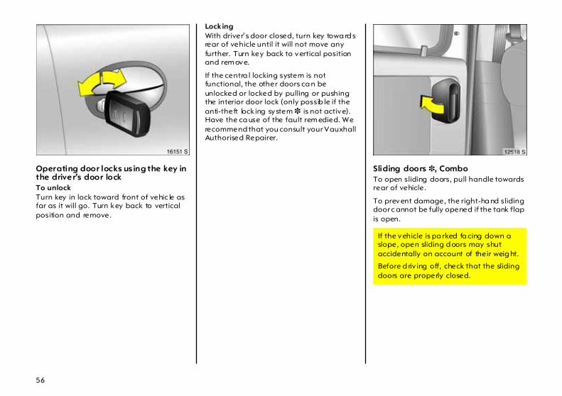
Operating door locks us ing the key in the driver’s door lock To unlock Turn key in lock toward front of vehic le as far as it will go. Turn key back to vertical position and remove.
Locking With driver’s door closed, turn key towa rd s rear of vehicle until it will not move any further. Turn key back to vertical position and rem ove.
If the centra l locking system is not functional, the other doors ca n be unlocked or locked by pulling or pushing the interior door lock (only possib le if the anti-theft lock ing system 3 is not active). Have the ca use of the fault rem edied. We recommend that you consult your Vauxhall Authorised Repairer.
Sliding doors 3, Combo To open sliding doors, pull handle towards rear of vehicle.
To prevent damage, the right-ha nd sliding door c annot be fully opened if the tank flap is open.
If the vehicle is pa rked fa cing down a slope, open sliding d oors may shut accidentally on account of their weig ht.
Before d riv ing off, check that the sliding doors are properly closed.

57
Luggage compartmentLocking Turn key to vertica l position.
To unlock Turn key to horiz ontal p osition.
The lock is released by pressing the button.
Using the central locking system with the luggag e c om partment The luggage compartment lock cannot b e used to lock or unlock the central locking system or the a nti-theft locking system 3.
When unlocked, open the luggag e compartment by pressing the b utton.
Key slot in loc k in horiz ontal p osition The luggage compartment is loc ked and unlocked using the central lock ing system.
If the key is turned to the horizontal position after unlocking via the central lock ing system, the lugga ge com partment remains locked.
Key slot in lock in vertical p ositionThe lugg age compartment a lso remains locked when unlocking v ia the central locking system . Choose this position if the luggage compa rtm ent is to always b e locked. Turn the key anticlockwise past the resistance p oint as far as it w ill go.

58
Unlocking lugg age comp artment w hen doors are locked via central loc king system Turn key clockwise a s far as possible beyond the resistance from the vertical or horiz ontal position. Key cannot be withdrawn to safeguard a gainst being locked out.
Relock the luggage compartment by closing it and turning the key to the horizontal or vertical position.
In the horizonta l position, the lug gage compartment will be unlocked the next tim e the vehicle is unlocked via the central lock ing system.
Tailgate, Combo Open right-hand door from outside by raising door handle or from inside by pressing handle.
Release left-hand door from inside by pressing handle.
The doors are arrested at a 90° angle. To close, push the doors beyond the slight resistance.

59
Both doors c an be op ened up to 180°: Close the door slig htly from the 90° position, diseng age the stop lug from the guide rail and open the door completely .
If the rear doors are opened up to 180°, the rea r exterior lights are no long er visible. When driving in the dark, therefore, do not open the rear doors beyond the point at which they lock into position.
When closing, make sure that the stop lug properly engag es in the guide rail.
Notez The saloon has a handle on the inside of
the ta ilg ate to a ssist c losing.
z Fitting of acc essories on the tailga te will increase its w eight. If it becomes too hea vy, it will then not sta y open.
z The registration plate can only b e clearly seen if the tailgate is closed. I t is therefore not p ermitted to d rive with the tailgate open.
Do not drive with the luggag e compa rtm ent open when transporting bulky goods, since poisonous exhaust fumes ca n penetrate the interior d ue to air turbulence.

60
Vauxhall alarm system 3monitors
z doors, luggag e com partment, b onnet,
z the passenger c om partment,
z vehicle tilt, e.g. if it is raised,
z the ignition.
To activateAll d oors, windows, sun roof 3 and bonnet must b e closed. Press button p on the remote control ag ain within 10 seconds of lock ing .
Sw itching system on exclud ing m oni toring of the pa ssenger com partm ent and the vehicle t ilt e.g. if anim als a re to be left in the vehic le.
1. Close luggage comp artm ent and bonnet.
2. Press button in front of the c ourtesy light (with ig nition off); LED in the haz ard warning light button flashes a maximum of 10 seconds.
3. Close doors.
4. Switch on Vauxhall alarm system . LED lights up. After approx. 10 sec onds the system is activated, without monitoring of the p assenger compa rtm ent or vehicle tilt. The LED flashes until the system is switched off.

61
Light emit ting d iode (LED) During the first 10 seconds of Vauxhall alarm system activation:
z LED lights up = Test, switch-ondelay,
z LED flashes = Door, tailgate,bonnet openor system error,
After the first 10 second s of Vauxhall alarm system activation:
z LED flashes = System on,
z LED lights up forapprox . 1 second = Switch-off.
If a system fa ult occ urs, consult a workshop. We recom mend your Vauxhall Authorised Repairer.
To deact ivatePress button q on remote control.
If there is a fault in radio remote control, turn key in driver’s door lock toward front of vehic le as far as it will go. Then turn key bac k to vertical position and remove.
If the alarm is triggered w hen the driver’s door is opened, d eactivate the alarm by switching on the ignition.

62
Opening and closing tailg ate with Vauxha ll ala rm system a ctivated 1. To unlock: Turn key cloc kwise as far as
possible. Luggag e com partment is unlocked and m onitoring of the interior and vehicle tilt is disa bled.
2. Open lug gage compartment.
3. C lose lug gage compartment.
4. Locking: Turn key back to prev ious position. Monitoring of the interior a nd the vehicle tilt is enabled again after approx . 10 second s.
Ala rm Only a certain num ber of a la rm s are allowed to be triggered while the Vauxhall alarm system is switched on (this number is stipula ted b y law).
The alarm takes the form of z an acoustic signal (horn) a nd z a visual sig nal (haz ard warning lights).
The duration of the a larm signals is limited due to lega l regulations.
Alarm c an be cancelled by pressing a button on the radio remote control. The anti-theft warning system is switched off at the sam e time by pressing the button q.
63
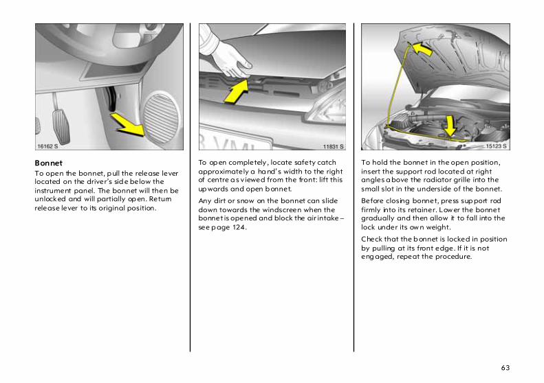
Bonnet To open the bonnet, p ull the release lever located on the driver’s sid e below the instrument panel. The bonnet will then be unlocked and will partially op en. Return release lever to its original position.
To op en completely , locate safety catch approximately a ha nd’s width to the right of centre a s v iewed from the front: lift this up wards and open b onnet.
Any dirt or snow on the bonnet can slide down towards the windscreen when the bonnet is opened and block the air intake – see p age 124.
To hold the bonnet in the open position, insert the support rod located at right angles a bove the radiator grille into the small slot in the underside of the bonnet.
Before closing bonnet, press sup port rod firmly into its retainer. Low er the bonnet gradually and then allow it to fall into the lock under its ow n weight.
Check that the b onnet is locked in position by pulling at its front edge. If it is not eng aged, repeat the procedure.

64
Seats, Interior
Seat adjustment see page 5.
Seat position Ad just driver’s seat such that with the driver sitting upright the steering wheel is held in the area of its upper spokes with the driver’s arm s slightly bent.
The seat b ackrests must not be tilted too fa r back (recommend ed tilting angle approx. 25°).
Head restraint position The centre of the head restraint should be at eye level. Ad just to highest position if this is not possib le for extremely tall people, and adjust to lowest position for extrem ely small people.
Setting – see pa ge 6 and the next page.
Disregard can lead to injuries which could be fatal. Vehicle passengers should b e informed accordingly.
Disregard can lead to injuries which could be fa tal. Vehicle passengers should be informed ac cord ingly .

65
Head restraints Adjustment – see pag e 6.
To rem ove head restraints, release both springs by pressing and detach head restraint.
The rear, centre head restraint 3 in the Com bo cannot be removed.
Rea r hea d restraints 3 , Corsa In order to im prove v ision when rear seats are unoccupied, push hea d restraints as far down as possible. Push detent springs to relea se.
If the rear seats are occupied, adjust the rear head restraints to the occupants’ body size – see p age 6.
To increase luggage comp artm ent size – see p age 66, removing rear head restra ints 3: Push both detent springs to relea se, remove head restraint.
Rear, centre head restra int 3, Combo The head restraint can b e pushed right down to improve visib ility if the centre rear seat is unoccupied or to allow the rear seat bac krests to be folded down. To d o so, release b oth springs by p ressing.
If the centre seat is oc cup ied, set the head restraint to the first or second position acc ording to the height of the passenger.

66
Extending the luggage compartment, Corsa Cha ng ing angle of rear seat backrestRelease one-piece rea r seat back rest or split rea r set backrests 3 using ha ndles and tilt forward a little.
The rear seat b ackrests can be locked in two positions.
Fold ing down the rear seat backrestsSlot the latch plates of the seat belts in the holders 3 in the side trim cover.
Removing rear head restraints 3 – p ush detent springs to release – see page 65.
Remove the push-in sleeves for mounting the ISO-FIX child restraint system; see the accompanying instructions for the ISO-FIX child restraint system .
Unlock the single-piece rea r seat back rest or split rear seat backrests 3 b y pulling on the handles and fold it/them down onto the rear seat.

67
– or –Slot the latch plates of the seat belts in the holders in the sid e trim c over – see Fig . 11585 S on prev ious pag e.
Removing rea r head restraints 3 – push detent springs to release – see page 65.
Remove the push-in sleeves for m ounting the ISO-FIX child restraint system; see the accomp any ing instructions for the ISO-FIX child restraint system.
Raise front edge of single-piece ba ckrest or split backrest 3 and tilt forward.
Unlock the single-piece rear seat backrest or split rear seat bac krests 3 by pulling on the handles and tilt it/them forwards.
Repositioning the rea r sea tsAfter repositioning, audibly engage the bac krest in the intermediate position or full upright position. There is a lock indicator 3 on the handles. If the backrest is properly eng aged, the red field 3 will not be visible on the handle.
Fold the rear seat d ow n and push it into place b etween the back rest and the vehicle floor. Press on the front edge of the rear seat to lock it audibly into p la ce.
Refit the hea d restraints 3 .
The three-point seat belt on the centre rear seat can only be pulled out of the retrac tor 3 if the rear seat b ackrest is eng aged.

68
Removing lugga ge compa rtment coverTo rem ove, unhook the retaining strap s from the ta ilg ate.
Remove the cover from the side guides and place it behind the seat backrests.
Fit in reverse order.
Notes on load ing see page 74.
Luggage com partm ent ex tension,Combo Fold ing down the rear seat backrestsRemove rear, outer head restraints 3 . Push detent springs to release, see pa ge 65. Push rear, centre head restraint 3 down as fa r as possible. Push detent spring s to relea se – see pag e 65.
Remove the push-in sleeves for mounting the ISO-FIX child restraint system; see the accompanying instructions for the ISO-FIX child restraint system .
Unlock one single-piece rear sea t backrest or both using pushbuttons and fold down onto rear seat.
– Or –Remove rear, outer head restraints 3. Push detent springs to release – see pag e 65. Push rea r, centre head restra int 3 down as far as possib le. Push detent springs to release – see page 65.
Hook seat belt buckles on rea r seat bac krests.
Remove the push-in sleeves for m ounting the ISO-FIX child restraint system; see the acc om panying instructions for the ISO-FIX child restraint system.
Pull up one or both rear seat cushions using straps provided .

69
Disengage one or b oth rea r seat backrests using the pushbuttons and fold down.
Rep osi tioning the rear seatsEngage rear seat back rest audibly in position.
Push back rear sea t cushions.
Insert outer rear head restraints 3.
The three-point sea t belt on the centre rea r seat can only b e pulled out of the retractor 3 if the rear sea t backrest is engaged.
Folding d own the front pa ssenger sea t 3 Push p assenger seat head restraint down and remove – see pa ge 65.
Tilt passenger seat back rest forwa rd by lifting the release lever.
To move upright, push release lever forwards and audibly latch front passenger seat back rest.
Notes on load ing see page 74.
Lashing eyes 3 The lashing eyes in the lug gage compa rtm ent are for securing transported items to prevent them from slipping around.
70
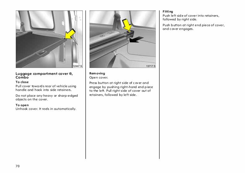
Luggage compartment cover 3, Combo To closePull cover towa rd s rear of vehicle using handle and hook into side retainers.
Do not place any heavy or sharp-edged objects on the cover.
To open Unhook cover. It reels in automatically.
Rem oving Open cover.
Press button at right side of c over and engage by pushing right-hand end p iece to the left. Pull right side of cover out of retainers, followed by left side.
Fitting Push left sid e of cover into retainers, followed by right side.
Push b utton at right end piece of cover, and c over engages.

71
Safety net 3, Com bo The safety net ca n be fitted behind the rear seats or, with the rear seat backrest folded down, b ehind the front seats.
Passeng ers m ust not be carried behind the safety net.
There are two installation openings in the roof frame: Open cover. Suspend upper net rod at one side and engage in position. Pull net rod apart, suspend at other side and enga ge in p osition. Close c over.
Fit ting behind the rear seats Fold d own both rear seat backrests, hook tensioning stra ps into lashing eyes in vehicle floor a nd tighten them. Rep osition rear seat backrests and lock them into position.
Fitting behind front seats Pull up both rear seat cushions. Fold down rear seat backrests. Hook tensioning stra ps into lashing eyes in vehicle floor a nd tighten them.
Removing Swivel tensioning strap length adjusters upward and unhook straps. Open the cover. Unhook upper net rod and close cover.

72
Load compartment grille 3, Com bo A load c om partment g rille is provided behind the front seats to prevent the vehic le occupants from being injured by loose cargo.
Sp lit load comp artment g rille 3 To enlarge the load compartment, the grille can be moved forwards on the front passenger’s side.
Push head restraint on front pa ssenger’s seat down as far as it will go – see page 65.
Tilt front p assenger’s seat bac krest forward by raising release lever and p ush down to lock in position.
Engage lever on load c om partment g rille at top position, as shown in illustration.
Engaging the lever prevents dama ge to the front passenger’s seat.
Position load compartment grille ab ove retainer in front passeng er’s seat backrest.
Lock load com partment g rille in retainer. To do so, engage lever at bottom position, as show n in illustration.
Notes on load ing see page 74.
Lashing eyes 3 Lashing eyes are provid ed in the load compa rtm ent so that cargo can be secured to prevent it from slipping.
The load c om partment grille must always be locked in one of the retainers when the vehicle is in use, and the lever must be engaged at its bottom position.

73
Bag hangers 3 On the back of the rear seat back rest there are two fixtures on which carrier b ags can be hung. Maxim um load: 10 kg.
Stow age compartment 3 beneath passenger seatLift tray by grasping recessed edge and pull forwards. Maximum load : 1 kg. To close the tray push it in and lock it in plac e.
Stowage compartment above front seats, Combo The compartment is only suitable for stowing light objects. Max imum load: 15 kg.
Secure objects to prevent them from falling out a nd causing injury.

74
Notes on loading the vehicle
z Heavy objec ts in the lug gage/load com partment should be placed as far forward as p ossible against the rear seat backrests or, if the rear seat backrests are folded down, ag ainst the front seat backrests. If objects are to be stacked, the heav ier objects should be placed at the bottom. Unsecured objects in the lugga ge/load compartm ent would be thrown forward with great force, for instance in the event of heavy brak ing.
z Secure heavy objec ts with lashing straps 3 a ttac hed to lashing eyes 3 – see page 72. If heavy loads slip when the vehicle is braked heavily or driven around a bend, the handling of the vehicle may chang e.
z Com bo: If objects are transported in the load c om partment, the split load compa rtm ent grille 3 must always be locked in one of the retainers and the lever m ust be enga ged at its bottom position – see page 72.
z Com bo: C lose the luggage compartment cover so there is no reflection in the rear window.
z If objects are being transp orted in the luggage/load compartment, the rear seat backrests must be locked in position – see p ages 67, 69.
z Do not a llow the load to protrude ab ove the upp er edge of the rear seat back rests, or above the upper ed ge of the front seat b ackrests if the rear seat back rests a re folded down.
z The warning triangle 3 and first-aid kit (cushion) 3 m ust always be freely accessible.
z Do not place any objects in front of the rea r window or on the instrument pa nel. They are reflected in the glass, obstruct the driver’s view and will be thrown through the vehicle, for insta nce in the event of heavy b ra king.
z Com bo: when stowing objects in the stow age compartment above the front seats, sec ure against falling out.
z No objects must be placed in the area in which the airbags inflate, as they could cause injury when the airbags are trig gered.
z The load must not obstruct the operation of the hand brake and the gears or restric t the driver’s freed om of movement.
z Do not drive with lugga ge compa rtm ent open when tra nsporting bulky objects, for exam ple, since toxic exhaust fumes could penetra te the interior.
z Weights, payload and roof loa d – see page 234.
z Driv ing with a roof load (see pages 138, 141, 160) increases the sensitivity of the vehicle to crosswinds and has a detrimenta l effec t on vehicle handling owing to the vehicle’s higher centre of gravity.
Disregarding instructions ca n lead to injuries which could be fatal. Vehicle passeng ers should be inform ed accordingly.

75
Cigarette lighter ) 3 In front centre console
Press in cigarette lighter with ignition switched on. Switches off autom atically when elem ent is glowing. Withdraw cigarette lighter.
Accessory socket 3 The accessory socket or cigarette lighter socket can be used to c onnect electrical accessories. The socket is op erational when the ignition is switched on. Use of the socket disc harges the battery if the engine is not running. Do not damage the socket by using unsuitable plug s.
The maximum power c onsumption of electrical ac cessories m ust not exceed 120 w atts.
Do not connect any current-delivering acc essories, e.g. electrical charging devices or b atteries.
E lectrical ac cessories connected to the socket must c om ply with the electromagnetic compatibility requirements la id d ow n in DIN VDE 40 839, otherwise vehicle malfunctions may oc cur.

76
Ashtray 3 To be used only for ash and not for combustible rubbish.
Front ashtray 3 Open the ashtray cover to the resista nce point.
To empty , open the ashtra y cover fully beyond its resistance p oint, causing the insert to lift. Grip both sides of the ashtra y insert a nd pull upwards.
To enlarge the stora ge c om partment remove the ashtray com pletely.
Rear a shtray 3 To open, swivel the cover upwards.
To empty, lift the cover and pull the ashtray out upwards by its c over.
Disreg ard c an lead to injuries which may be fatal. Vehicle pa ssengers should be informed accordingly.

77
Glove com partm ent To open, pull hand le upwards.
On the inside of the glove c om partment cover there is a pen holder.
In vehicles w ith Infotainment system 3, the telematics unit 3 can be housed in the glove compartment.
Stow age compartment 3 for glasses On driver’s sid e: Fold down to open.
Coin holder 3 In the centre console.
Sun visors Use the sun v isor to protect from glare by pulling it d ow n and swivelling it to the side.

78
Safety systems Three-stage restraint system Comprising:
z Three-point seat belts,
z Belt tensioners at the front seats,
z Airbag system s for driver’s seat, passenger seat 3 and outboard rear seats 3.
The three stag es are a ctivated in sequence depending on the seriousness of the accident:
z The automa tic seat belt locking devices prevent the belt strap from being pulled out and thus ensure that the vehicle occupants are retained in their seats.
z The front seat b elt buckles are p ulled downwards. As a result, the seat b elts are instantaneously tightened and the occupants are made aware of the deceleration of the vehicle at a very ea rly stage. This reduces the stress placed on the body.
z The airbag systems a re also triggered in the event of serious accidents and form a safety cushion for the occupants.
Be sure to rea d the a ccompanying desc ription of the child restraint system !
The airbag systems 3 serve to supplement the three-p oint sea t belts and belt tensioners. The seat belts must therefore always be worn. Disregard of these instructions may lead to injuries or endanger life. Vehicle p assengers should be informed accordingly.

79
Seat belts In the event of an accident, persons not wearing sea t belts enda ng er their fellow oc cup ants and themselves.
Warning light X for the seat belt – see page 29.
Sea t belts are desig ned to be used by only one person at a time. They are not suitable for c hildren under 12 yea rs of ag e or 150 cm unless an appropriate child restra int system is used .
For children up to 12 years of age we recommend the Vauxhall child restraint system – see pa ge 95.
Three-point seat belts The vehicle is equipped with three-point seat belts with automatic retrac tors and locking d evices, allowing freedom of body movement although the spring tensioned belts always ensure a snug fit. Correct seat position – see page 85.
The belt has a "vehicle sensitive retra ctor" which is designed to lock during hea vy acc eleration or deceleration in any direction.
Alwa ys wea r your seat belt, and that means also in urb an traffic and when you are a rear seat passenger. It can save your life!
Pregnant women m ust alwa ys wear a seat belt – see page 82.

80
Belt tens ioners The front seat belts are equip ped w ith belt tensioners. In the event of a head -on or rea r-end collision of a certain severity, the buckles are pulled downwards, thereby tightening the belts.
Actuation of belt tensioners is indicated by illum ina tion of control indica tor v, see next p age.
The belt tensioners must be replaced after activation. We recommend that you consult your Va uxha ll Authorised Repairer.
If the seat belts are undama ged the operation thereof is unaffec ted, even if the belt tensioners have b een trigg ered .
Further information – see page 83.
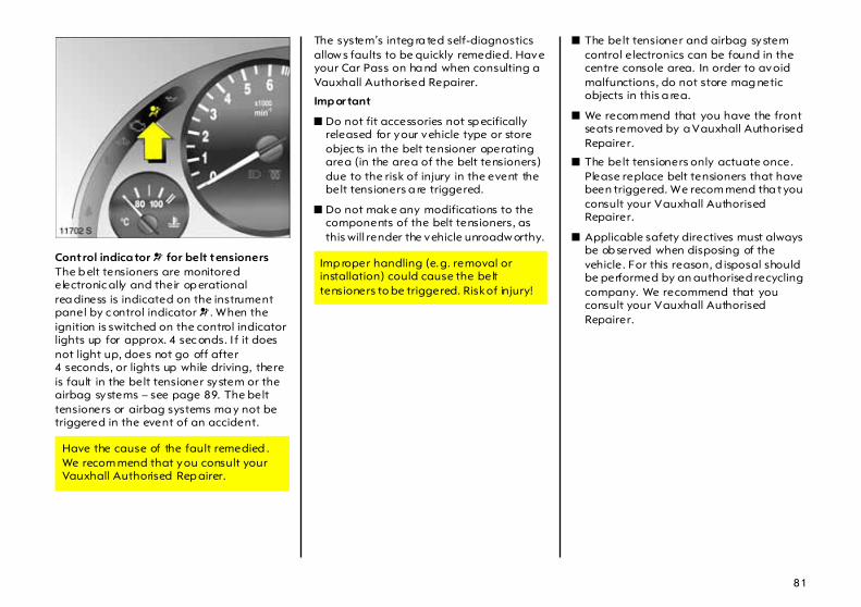
81
Control indica tor v for belt tensioners The b elt tensioners are monitored electronic ally and their op erational rea diness is indicated on the instrument panel by c ontrol indicator v . When the ignition is switched on the control indicator lights up for approx. 4 sec onds. I f it does not light up, does not go off after 4 seconds, or lights up while driving, there is fault in the belt tensioner system or the airbag systems – see page 89. The belt tensioners or airbag systems ma y not be triggered in the event of an accident.
The system’s integ ra ted self-diagnostics allow s faults to be quickly remedied. Have your Car Pass on ha nd when consulting a Vauxhall Authorised Repairer.
Imp or tant
z Do not fit accessories not sp ecifically released for your vehicle type or store objec ts in the belt tensioner operating area (in the area of the belt tensioners) due to the risk of injury in the event the belt tensioners a re triggered.
z Do not make any modifications to the components of the belt tensioners, as this will render the vehicle unroadw orthy.
z The belt tensioner and airbag system control electronics can be found in the centre console area. In order to avoid malfunctions, do not store mag netic objects in this a rea.
z We recom mend that you have the front seats removed by a Vauxhall Authorised Repairer.
z The belt tensioners only actuate once. Please replace belt tensioners that have been triggered. We recom mend tha t you consult your Vauxhall Authorised Repairer.
z Applicable safety directives must always be ob served when disposing of the vehicle. For this reason, d isposal should be performed by an authorised recycling company. We recommend that you consult your Vauxhall Authorised Repairer.
Have the cause of the fault remedied . We recom mend that you consult your Vauxhall Authorised Rep airer.
Imp roper handling (e.g. removal or installation) could cause the belt tensioners to be triggered. Risk of injury!

82
Using the belts Fitting seat bel ts Pull the belt out of the retractor and guide it across the body, making certain that it is not twisted.
Insert latch plate into buckle. Backrest must not be tilted too far back as this would affect the opera tion of the seat belts; recommended tilting a ng le app rox . 25°. The lap belt must be straight and lie snugly against the body. Tighten lap belt at frequent intervals whilst driving by tugging diagonal pa rt of belt.
Bulky clothing prevents the belt from fitting prop erly. The belt must not rest against ha rd or fragile objects in the pockets of your clothing (e.g. ballpoint pens, keys, spectacles) because these could cause injury. Do not place any objec ts (e.g. ha ndb ags, mobile phones) b etween the belt and your body.
Height adjustm ent of front seat belt upper a nchorage points:
1. Pull b elt out slig htly.
2. Press b elt guide or, in 5-door saloon, push button down.
3. Set desired height.
4. Allow to loc k audibly into p osition.
Do not adjust height while driving .
Adjust height setting such that seat belt runs over and lies against the shoulder. The belt must not run over the neck or upper arm – see page 79, Fig . 13190 S.
On pregnant women in particular, the lap belt must be positioned as low as possible ac ross the pelv is so as not to put too much pressure on the abdomen.

83
Removing the belt To rem ove the belt, depress the red pushbutton on the buck le; the belt will retract autom atic ally.
Three-point seat b el t on centre rear sea t The belt can only be pulled out of the retractor 3 if the rear seat backrests are engaged in their retainers – see page 67.
Testing the belts Plea se check all parts of the b elt system occasionally for dama ge a nd correct operation. H ave da maged parts replaced . In ca se of an accident, please replace overstretc hed belts and triggered belt tensioners. We recom mend consulting your Vauxhall Authorised Repairer.
Do not perform any altera tions on the belts, their anchorages, the automatic retrac tors or the belt buck les.
Make sure that b elts are not da maged or trapped by sharp-edged objec ts.

84
Vauxhall Full Size airbag system Front airb ag The front airbag system is identified by the word AIRBAG on the steering wheel and above the glove c om partment 3.
The front airbag system comprises:
z an airbag with inflator in the steering wheel and a second one in the instrum ent panel 3,
z the control elec tronics with impact sensor,
z the a irba g system s control indicator v in the instrument panel.
z seat occ upa ncy rec og nition 3,
z the control indicator for Va uxha ll child restraint systems y with transponders 3 in the courtesy light.
The front airb ag system will be trigg ered :
z depending on the severity of the accident,
z depending on the type of impact,
z within the range shown in the illustration,
z indep endently of the side airb ag system 3 and curtain airbag system 3.
Exception: Passenger sea t with seat occupancy recognition system 3 . The seat occupancy recognition system deactiva tes the passenger front and side airbags if the passenger seat is unoccupied or a Vauxhall child restraint system with transponders 3 has been fitted to the passenger seat. Seat occupa ncy recognition – see p age 89. Vauxhall child restraint system with transponders 3 – see pag e 96.
Examples of events triggering the front airbag system:
z Impact against a non-y ielding obstacle: The front airbags are trigg ered at low vehicle speed.
z Impact against a yield ing obstacle(such as another vehicle): The front airbags are only triggered at a hig her vehicle speed.

85
When trigg ered , the front airbags inflate in milliseconds and form a safety cushion for driver and front passeng er. The forw ard movement of the driver and front passenger is checked and the risk of injuries to the upper body a nd head thereby substantially reduced.
No im pairment of view will occur, because the a irb ags inflate and deflate so quickly that it is often not even noticed in an accident.
The front airbag system will not be triggered in the event of z the ignition is switched off, z minor frontal collisions,z accidents in which the vehicle overturns, z collisions involving a side or rear impa ct, that is to say, if it w ould not be of benefit to the oc cup ants.
The front airbag system provides optimum p rotection when the seat, back rest and head restra int are correctly adjusted: Adjust the driver’s seat according to the occupant’s height so that when the driver is sitting up rig ht, the steering wheel is held in the a rea of its upper sp okes with the d river’s arms slightly bent. The pa ssenger seat should be as far back as possible, with the back rest upright (see pa ges 5, 64, 82). Do not place the head, b od y, hands or feet on the covers of the airbag systems.
Do not place any objects in the area in which the airb ags inflate. Im portant inform ation – see page 92.
The three-point seat belt must be correctly fitted – see page 82.

86
In addition, the front airb ag system will not be triggered for the front passenger in versions with seat occupancy recognition 3 if
z the front passenger’s seat is unoccupied,
z there is a prop erly fitted Va uxha ll child restraint system with transponders 3 . Seat oc cup ancy recognition, see page 89. Vauxhall child restraint system with transponders 3 – see page 96.
Side airb ag 3 The side a irb ag system is identified by the word AIRBAG on the outb oa rd sides of the front seat backrests.
The side a irb ag system c om prises:
z An airbag with inflator in the bac k of the driver’s and front passenger’s seat respectively ,
z The control electronics,
z The side impact sensors,
z The airb ag systems control ind icator v in the instrum ent panel,
z Seat occupancy recognition 3,
z The control indicator for Va uxha ll child restraint systems y with transponders 3 in the courtesy light.
The side airbag system will be triggered:
z Depending on the severity of the accident,
z Depending on the type of impa ct,
z Within the range shown in the illustra tion on the centre d oor pillar of the driver’s or front passenger side,
z Independently of the front a irba g system.
Exception: Pa ssenger seat with seat occupancy recognition system 3. The seat occupancy recognition system dea ctivates the pa ssenger front and sid e airbags if the passenger seat is unoccupied or a Vauxhall child restraint system with transponders 3 has been fitted to the passenger seat. Seat occupa ncy recognition – see p age 89. Vauxhall child restraint system w ith transponders 3– see page 96.
Seat belts must therefore always be worn. The front airbag system serves to supplement the three-point seat belts. If you do not wea r your seat belt you risk being seriously injured, or even thrown from the vehic le, in the event of an accident.
In the event of an accident the belt helps to keep you in the correct seating position, so that the front airb ag system can provide you with effective protection.

87
When triggered, the sid e airbag inflates in milliseconds to form a safety cushion for the d river or front passenger in the respective door area. This substantially red uces the risk of injury to the upper body in the event of a sid e-on collision.
The side airba gs will not be triggered in the event of
z the ig nition is sw itc hed off,
z fronta l collisions,
z accidents in which the vehicle overturns,
z collisions involving a rear impac t,
z collisions involving a side imp act outside the passenger cell.
In addition, the side airbag system w ill not be triggered for the front passenger in versions with seat occupa ncy recognition 3 if z the front p assenger’s seat is unoccupied
z there is a properly fitted Vauxhall child restraint system with transpond ers 3. Seat occupancy recognition, see page 89. Va uxha ll c hild restraint system with transp onders 3 – see p age 96.
Cur tain ai rbag 3 The curtain a irba g system is identified by the word AIRBAG on the roof pillar trim.
The curtain a irba g system com prises:
z an airbag w ith inflator in the roof frame on the d river’s and front passenger’s side respectively,
z the control electronics,
z the side im pact sensors,
z the airb ag system s control indicator v in the instrument panel.
There must be no objects in the area in which the airb ag inflates or in the a rea between the seat backs and the vehicle body. Do not place the hands or arms on the covers of the airba g systems. Imp ortant information – see page 92.
The three-p oint seat b elt m ust always b e correctly fitted – see page 82.

88
The curtain airbag system will be triggered:
z Depend ing on the severity of the accident,
z Depend ing on the type of impac t,
z Within the range show n in the illustration on the centre door pillar of the driver’s or front passenger side,
z Together with the side airbag system,
z Irrespective of seat occupa ncy recognition,
z Ind ependently of the front airbag system .
When triggered, the curtain airbag inflates in millisecond s to form a sa fety cushion in the head area on the side of the vehicle affected . This substantially reduces the risk of injury to the head in the event of a side-on c ollision.
The curtain airbags will not b e triggered in the event of
z the ignition is switched off,
z frontal collisions,
z accidents in which the vehicle overturns,
z collisions involving a rear impact,
z collisions involving a side impact outside the passenger cell.
There m ust be no objec ts in the area in which the airbag inflates. Do not place the hands or arms on the covers of the airbag systems. Important information – see page 92.
The three-point seat belt must always be correctly fitted – see pag e 82.

89
Control indica tor v for airb ag systemsThe a irb ag systems are monitored electronic ally together with seat occupancy recognition 3 and the belt tensioners. Their opera tional readiness is shown b y control ind icator v in the instrument panel. When the ignition is switched on, the control indic ator lights up for approx. 4 seconds. If it does not light up, d oes not go out after 4 seconds or lights up while driving, there is a fault in the airbag systems, seat occupancy recognition 3 or the belt tensioners – see page 81. The system s m ay fail to trigg er in the event of an accident.
The system’s integ ra ted self-diagnostics allow s faults to be quickly remedied. Have your Car Pass on ha nd when consulting a Vauxhall Authorised Repairer.
Seat occup ancy r ecog ni tion 3 The seat occupa ncy recognition system deactivates the front and side passeng er airbags if the front passenger seat is unoccupied or a Vauxhall child restraint system with transponders 3 has been fitted to the front passenger seat. The curtain airbag system remains activated.
The control indica tor for sea t occupancy recognition is located in the courtesy light. If this control indicator lights up after the ignition is switc hed on for approx. 4 seconds, the vehic le is equip ped with seat occupancy recognition – see Fig. 12097 S on page 90.
If a Vauxhall child restraint system w ith tra nsponders 3 is installed, this control indica tor remains on after the ignition has been sw itched on as soon as the system ha s d etec ted the seat. Only then c an the child restraint system be used on the passenger seat.
In ad dition, vehicles with seat occupancy recognition can be id entified by the sticker on the front passenger seat.
Vauxhall child restraint systems with transponders 3 are autom atically detected if correctly fitted to the front passenger seat. When these child restraint systems are being used on the front passenger seat, the front and side airbag systems for the front passenger seat are deactivated. The curta in a irb ag system remains a ctivated. Pay a ttention to the seat oc cup anc y recog nition 3 control indicator – see p age 90.
6
Have the cause of the fa ult remedied. We recommend that you consult your Vauxhall Authorised R epairer.

90
Vauxhall child restraint systems with transponders 3 are identified by a sticker.
Wa rning lig ht y for Vauxhal lchild restraint systems with transponders 3 The presence of an Vauxhall child restraint system with transponders 3 is ind ic ated after the ig nition has been switched on by permanent illum ination of the c ontrol indica tor y in the courtesy light, as soon as the seat occupa ncy recognition system ha s d etec ted the child restraint system.
If the control indicator d oes not illuminate whilst driving, the front and side airbag have not been deactivated on the passenger side. Risk of fatal injury to the child – fit child restraint system to rear seat. Have c ause of fault remedied. We recommend that you consult your Vauxhall Authorised Repa irer.
If a child restraint system is incorrectly fitted or the transp onders are faulty, the control indicator will flash. Chec k that child restraint system has been fitted correctly. Fitting child restraint system with transponders 3 – see p age 96.
Only Vauxhall child restraint systems with transp onders 3 can be fitted on the front passenger seat; the use of systems without transponders poses a danger to life.

91
If the control indicator does not illuminate with a c orrectly insta lled child restraint system there is a fault – risk of fa ta l injury to the c hild. Fit child restra int system to rea r seat. Ha ve cause of fault remedied . We recommend that you consult your Vauxhall Authorised Repairer.
If no Vauxhall child restraint system with transponders 3 is installed the control indicator must neither illuminate nor flash, since the passenger side airb ag systems would not be trigg ered . Have the c ause of fault remedied. We recommend that you consult your Vauxhall Authorised Repairer.
If the Vauxhall child restraint systemwith transp onders 3 has been fitted according to the instructions, the control indicator for Va uxha ll restra int system s with transp onders must light up in the courtesy light when the ignition is switched on.
If the control indicator does not illuminate w hilst driving, the airbag systems have not been deactivated on the passenger sid e. Risk of fatal injury. In this case, fit child restraint system to rear seat. Have cause of fault remedied. We rec om mend that you consult your Vauxhall Authorised R epairer.
92
Im portant
z Acc essories and other objects must not be affixed or placed in the a rea in which the airbags inflate a s they could cause injury if the airbags are trig gered.
z Do not p la ce a ny objects between the airb ag systems and the vehicle occ upa nts; d ang er of injury .
z Use the hooks in the roof frame only to hang up light articles of clothing or c oa t hangers. Do not place any objects in the pockets of the hanging items – risk of injury.
z The airbag system s and belt tensioner control electronics c an be found in the centre c onsole area. In ord er to avoid malfunctions, do not store magnetic ob jects in this area.
z Do not stick a nything on the steering wheel, instrument p anel, front seat backrests or roof fram e in the vicinity of the airbags, or on the front pa ssenger’s seat cushion, or cover any of those areas with other materials.
z Use only a dry cloth or interior cleaner to clean the steering wheel, instrum ent panel, front seat b ackrests, roof fram e and seat cushion of the front passenger seat. Do not use any a ggressive cleaning agents.
z Only protective covers whic h are approved for your Corsa/Combo w ith side airb ag may be fitted on the front seats. When fitting the protective covers, make sure that the airbag units on the outboard sides of the front seat back rests a re not covered.
z The airb ag systems are triggered indep endently of each other depending on the severity of the accident and the type of impa ct. The side airbag system and the curtain airbag system are triggered together.
z Each airbag can be trig gered only once. Onc e triggered, an airbag must be rep laced without delay. We recomm end that you consult your Vauxhall Authorised Repairer.
z The speeds, d irections of m ovement and deform ation p roperties of the vehicles, and the properties of the obstac le concerned, determine the severity of the accident and triggering of the airbags. The degree of da mage to your vehic le and the resulting repair costs alone are not indicative tha t the criteria for triggering of the airbags were m et.
z Do not perform any alterations on the components of the airbag system, as this would render the vehicle unroadworthy.
z We recom mend ha ving the steering wheel, the instrument panel, all panelling parts, the door sea ls, the handles and the seats removed by your Vauxhall Authorised Repairer.
z Applicable safety directives must always be ob served when disposing of the vehicle. For this reason, d isposal should be performed by an authorised recycling company. We recommend that you consult your Vauxhall Authorised Repairer.
The systems can b e triggered abrup tly and cause injury if they are ha nd led improperly.
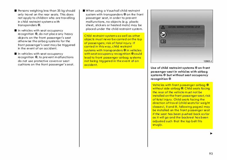
93
z Persons weighing less than 35 kg should only tra vel on the rear seats. This does not ap ply to children who are travelling in c hild restra int system s w ith transponders 3.
z In vehicles with seat occupancy recognition 3, do not plac e any heavy ob jects on the front passenger’s seat otherw ise the airba g systems for the front passenger’s seat ma y be trigg ered in the event of an acc id ent.
z In vehicles with seat occupancy recognition 3, to prevent m alfunctions do not use protective covers or sea t cushions on the front passenger’s seat.
z When using a Vauxhall child restraint system with transponders 3 on the front passenger seat, in order to prevent malfunctions, no objects (e.g. plastic sheet, stickers or heated mats) may be placed under the child restraint system.
Use of child restra int systems 3 on fr ont pa ssenger sea t in vehicles wi th airba g systems 3 but wi thout sea t occupa ncy recognit ion 3
6
Child restraint system s a s well as other objec ts must never b e carried on the la p of passengers; risk of fatal injury. I f carried in this w ay, c hild restraint systems with transp onders 3 in vehicles with seat occupancy recog nition 3 could lead to front passenger airbag systems not being trig gered in the event of a n accident.
Vehic les with front p assenger airbag 3 without side airbag 3: Child seats fa cing the rear of the vehicle m ust not be installed on the front passenger sea t, risk of fa ta l injury. Child sea ts facing the direction of travel (child seats for weig ht classes I, II and III , following pag es) may be installed on the front p assenger seat if the seat has been p ushed back a s far as it will go and the backrest ha s b een adjusted such that the lap b elt fits snugly.

94
Vehicles with front passeng er airbag can be identified by the word AIRBAG above the g love com partment and the warning stic ker on the side of the instrum ent panel, visible when the p assenger door is open.
A vehicle with side a irba gs can be identified b y the word AIRBAG on the outboard sides of the front seat backrests.
Sea t occupancy recognition 3 – see p age 89.
Use of child restra int systems 3 on fr ont pa ssenger sea t in vehicles wi th airba g systems 3 and wi th sea t occupa nc y recognit ion 3
Vehicles with side airbag 3: No child restraint system 3 ma y be fitted on the front passenger’s sea t; risk of fatal injury.
Only Vauxhall child restraint systems with tra nsponders 3 should be fitted on the front passeng er seats. Use of systems without transpond ers poses a danger to life.

95
Seat occupancy recognition in a vehicle is indicated by the control indica tor in the courtesy light. I f this control indicator lig hts for approx. 4 seconds when the ignition is switched on, it indica tes that the vehicle is equipp ed with seat occupancy rec ognition – see pa ge 89.
Seat occupancy recognition in a vehicle is also indicated by a sticker on the front passenger seat – see pa ge 94, Fig. 12106 A.
The seat occupancy recognition system detects Vauxhall child restraint systems with transponders 3 and switches off the front a nd side airbag systems for the front passenger’s sea t. The curtain airbag system rem ains activated. Seat occ upa ncy recognition – see pa ge 89.
Vauxhall child restraint systems with transponders 3 can be identified by the stic ker on the child restraint system.
Child restraint systems 3 The Vauxhall child restraint system is designed sp ecifically for your Vauxhall and thus provides optimum safety for your child in the event of impa ct. If a different child safety seat is used, follow the manufac turers’ instructions for fitting a nd use.
Selec ting the rig ht system Your child should be transported facing backwards in the car as long as p ossible. It is ap propria te to change the system when the child’s head c an no longer be p roperly supported at eye height. The child’s neck is still very weak and in an accident they suffer less stress in the semi-prone backwards position than w hen sitting up right.
Note z Children und er 12 years or under 150 cm
tall should only travel in an ap prop ria te child sa fety sea t.
z When transporting c hildren, use the child restra int system s suitable for the child’s weight.
z Ensure that the c hild restraint system is fitted correctly .
z The covers of the Vauxhall child restraint system can b e wiped clean.
z Do not stick anything on the child restra int systems and do not cover them with any other m aterials.
z Only allow child ren to enter and exit at the side fa cing away from the traffic.
z A child restraint system which has been subjected to stress in an accident must be replaced.
z You should also ob serve the instructions on installa tion and use supplied with the child restraint system.

96
Permissible options for fi tting a child safety sea t in your Corsa/Comb o
Weightandage class
Onfr ont
p assenger sea t
Ona rear
outb oard seat
Oncentre rear
seat
0:up to 10 kgor approx.10 months
B 1, + + U+ U
0+: up to 13 kg or approx.2 years
B 1, + + U+ U
I: 9 to 18 kgor approx.8 months to 4 years
B 2, + + U+ U
II : 15 to 25 kgor approx.3 to 7 years
B2 U U
II I: 22 to 36 kgor approx.6 to 12 years
B2 U U
B1 = p rov id ed: no front passenger airbagor with seat oc cup anc y recog nitionand Vauxhall child restraint system
withtransponders. Front passengerseat height adjustm ent also required .Front p assenger seat in highestposition a nd slid all the wa y back .Height adjustm ent of front p assengerseat belt set to low est position.
B2 = p rov id ed: without side airbag,with front passeng er seat slid all the way back or withseat oc cup anc y recog nition and
Vauxhallchild restraint system withtransponders. Front passenger seatheig ht a djustment also required. Front p assenger seat in highestposition a nd slid all the wa y back .Make sure vehicle seat beltis as straig ht a s p ossible b etweenshoulder and deviation pointin vehicle.
U = universally suitable in conjunction withthree-point seat belt.

97
+ = seat with ISO-FIX m ountingava ila ble. When mounting with ISO-FIX, only ISO-FIX child restraintsystems that have been approved forthe vehicle may be used .We recommend that you contactyour Vauxhall Authorised Repairer.
++ = seat with ISO-FIX m ounting availab lefor Corsa only; only child safetysystems approved for the vehicle may be used
Exterior mirrors For the safety of pedestrians, the exterior mirrors will swing out of their normal mounting position if they are bumped. Reposition the mirror by applying slight pressure 3.
Aspherical ex terior mirror 3 increases the fie ld of view . Estimating the distance away of vehicles following you is only possible to a limited extent b ecause of slight distortion.
Sport exterior mirrors 3 For the safety of pedestrians, the mirrors are released from their mountings if they are bumped with sufficient force.
Relocate the d isenga ged m irror housing in its mountings and engage by applying pressure.

98
Head restraints Do not attach objec ts or com ponents that are not approved for your Corsa/Combo to the head restraints, since they can red uce the p rotection prov ided by the head restraints a nd could be catapulted uncontrollably through the vehicle in the event of hard brak ing or an accident.
Safety accessories 3 The wide range of Vauxhall a ccessories allow s you to equip your Corsa/Comb o as you desire. In addition to safety accessories, items for improving com fort and a comp lete rang e of vehicle care prod uc ts, there are m any articles which will be of g reat va lue to you when needed.
"Genuine Vauxhall Parts and Accessories" guarantee high q ua lity and accurate fit.
Your Va uxha ll Authorised Repairer w ill be ha ppy to ad vise you, for exam ple w ith regard to: z Vauxhall child restraint systems, z Tow ropes, z Tow rods, z Jump lead s, z Sp are bulb kit, z Sp are fuse kit,z Halogen fog lights, z Mud flaps, z Magnetic light, z Warning tria ngle, z First-aid k it, z First-aid k it (cushion).
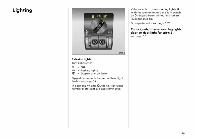
99
Lighting
Exterior lightsTurn light switch:
7 = Off 8 = Parking lights 9 = Dipp ed or m ain beam
Dip ped beam , main b eam and head lig ht flash – see p age 15.
In positions 8 and 9, the tail lights a nd numb er plate light are also illuminated.
Vehicles with d aytime running lights 3: With the ignition on and the light switch on 7 , dipped beam w ithout instrument illumination is on.
Driving ab road – see pag e 102.
Turn s ignals, hazard warning lights,door-to-door light function 3 see page 16.

100
Headlight range adjustm ent ? Manual hea dlight range adjustm ent 3 Adjust headlight range to four stages of vehic le load ing with dipped beam switched on: Turn adjuster wheel to desired position.
Correct adjustment of the headlight range red uces dazzle for other road users.
Corsa Sa loon, Com bo Comb i,Comb o Tour
z Front sea ts occupied = 0
z All seats occupied = 1
z All seats occupied andluggage compa rtm ent load = 2
z Driver’s seat occupied andluggage compa rtm ent load = 3
Corsa deliver y va n, Com bo Van
z Seats occupied = 0
z Seats occupied andhalf load in load compartment = 1
z Seats occupied andfull load in load c om partment = 2
z Driver’s seat occupied andfull load in load c om partment = 3
Correct ad justment of the headlight rang e reduces d azzle for other roa d users.
Autom atic headlig ht ra nge ad justment 3 Controls headlight range in vehicles with Xenon head lig ht system . If c ontrol indicator q lights w hile driving, there is a fault. Have the cause of the fault remedied imm ediately. We recomm end that you consult your Vauxhall Authorised Repa irer.

101
Fog lights >3 On = Press > . > lights in instrum ent
panelOff = Press > again or
switch ignition or light off
Fog tail l ight r On = Press r. r lights in instrument
panelOff = Press r again or
switch ignition or light off
The fog ta il lights on the vehicle are deactivated when towing a caravan/trailer.
Reversing lightsCom e on when reverse gear is engaged and ignition is switched on.
Courtesy light 0 Comes on when a door is opened. Once the door ha s b een shut it goes out after a certain delay 3 or when the ignition is turned on 3.
To keep the courtesy light on, press the lig ht switch.
Automatically regulated centre console lighting 3 Spotlight in housing of interior mirror.
Daylight-dependent, automa tic ally regulated centre console lig hting with ignition switched on.
Instrument il lumination k Com es on with exterior driving lights. Brightness can be adjusted with adjuster wheel.
Information display illumination 3 Com es on when the ignition or infota inm ent system is on. Brightness can be adjusted w ith a djuster w heel.

102
Front reading lights 3 With ignition switched on:
On = Press buttonOff = Press button again
Rear courtesy light,rear reading light 3 On = Move switch to right
Off = Move switch to left
Light switches on w hen adoor is opened = Switch in middle
Luggage com partm ent and loading area lighting 3 Comes on when the tailgate is opened.
Safeguarding the battery 3 Som e consum ers such a s the interior lighting switch them selves off after approx. 30 minutes if the ignition is off in order to protec t the battery charge.
Headlights when driving abroad The asymmetrica l dipped beam increa ses the fie ld of vision on the passenger side of the lane.
This causes g la re for oncom ing traffic if the vehicle is driven in countries where traffic drives on the opposite side of the road.
To avoid glare, place masking strip s on both hea dlights. We recomm end that you consult your Vauxhall Authorised Repa irer.

103
Windows, sun roof,folding top
Door windows The door w indows can b e operated with a crank.
Rear vent windows 3 To open = Push catch To close = Pull knee lever,
engage
Care must be taken w hen operating the electric windows 3 a nd electric sun roof 3. There is a risk of injury, particularly for children, and a d anger that articles could b ecome trapped.
Vehicle passeng ers should be inform ed accordingly.
Keep a close watch on the windows and sun roof when closing them. Ensure tha t nothing becomes trapped in them a s they move.
Before lea ving the vehicle, remove the ignition key in order to p revent unauthorized opera tion of the wind ow s and sun roof.

104
Electric windows 3 Operation with ignition switched on.
Two rocker sw itc hes in the driver’s door handle for the driver and front p assenger side d oor w indows. Ad ditional rocker switch in the front p assenger door handle.
Control ind icators in the switches show the opera tional status.
To opera te window in stages, tap appropriate switch. For automatic opening or closing, keep switch pressed for slightly longer; to stop window movem ent, tap switch again.
Safety func tion If the window g lass enc ounters resistanc e above the midd le of the window during autom atic closing, it is im med ia tely stopped and the window opened ag ain.
If the windows do not move easily (e.g . on account of frost), repeated ly ta p the switch for the wind ow in question until the wind ow ha s b een closed in sta ges.
Overload If the windows a re repeatedly operated at short intervals, the power sup ply is briefly cut off.
The system is protec ted by fuses in the fuse box – see page 188.
Fault If a utomatic opening or closing of the windows is not possible, activate window electronics as follows:
1. Close doors.
2. Switch on ignition.
3. Window com pletely open.
4. Close window a nd hold down rocker switch for at least another 5 seconds.
5. Repeat for ea ch window.

105
Sun roof 3 Tilt crank out of rec ess.
To open: Press unlocking b utton. Turn crank to left.
When the crank will not turn any further the sun roof ha s reached the comfort position, and air noise w ill be reduced .
To open beyond the comfort position: press unlock ing button a gain. Continue to turn crank to the left.
To close: Turn crank to rig ht.
When the crank will not turn any further the sun roof has reached the comfort position. Press unlocking button aga in and continue to turn crank to rig ht until sun roof is closed.
The unlock ing button is automatically relea sed when the sun roof rea ches the closed position.
To raise: Close sun roof a nd p ress unloc king button. Turn crank to rig ht.
To low er: Turn crank to left.
The unlocking b utton is autom atically released when the sun roof reaches the closed position.
After opera ting the sun roof, always return the crank to the recess.
Sun shad e The sun sha de c an be op ened and closed with the sun roof either closed or raised.
When the sun roof is opened, the sun sha de is also opened.
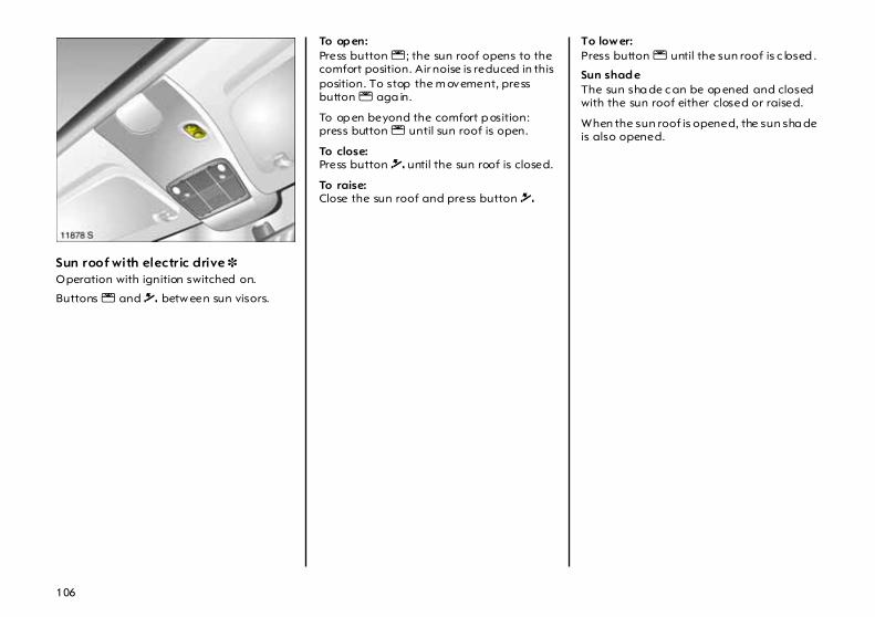
106
Sun roof with electric drive 3 Operation with ignition switched on.
Buttons l and \ betw een sun visors.
To op en: Press button l ; the sun roof opens to the comfort position. Air noise is reduced in this position. To stop the m ovement, press button l aga in.
To op en beyond the comfort p osition: press button l until sun roof is open.
To close: Press button \ until the sun roof is closed.
To raise: Close the sun roof and press button \
To low er: Press button l until the sun roof is c losed .
Sun shad eThe sun sha de c an be op ened and closed with the sun roof either closed or raised.
When the sun roof is opened, the sun sha de is also opened.

107
Fault If the electric drive fails, the system is protected by a fuse in the fuse box – see page 188. Until the fault is remedied, opera te the sun roof as follows:
Slide drive cover toward rear. Push in spring-load ed centre pa rt of drive shaft using screwdriver and rotate drive shaft until sun roof is closed .
Electrically operated folding sun roof 3, Saloon Operation with ig nition switched on.
Buttons \ and l between the sun visors.
To op en:Press button \ until folding roof is open.
To close: Press button l until folding sun roof is closed.
Note Release switch as soon as roof has rea ched end position.
Roof ca n only be operated at speeds of less than 75 mph (120 km/h).
Do not open frozen, icy or snow-covered roof.
When using a roof rack, check freedom of movement of electric folding sun roof in order to prevent dama ge.

108
Fault If a fault occurs, check relevant fuse in fuse box – see page 188. M anual op eration if e lectric drive fails:
Release c ourtesy light lens at side recess using screwdriver and remove.
Position screwdriver in vicinity of flights, relea se and remove light insert.
Unscrew b oth screws from drive cover and remove cover in d irection of arrow .

109
Take the emergency spanner from the glove compartment, insert it in the drive of the folding sun roof and turn until the roof is closed.
Electrically operated folding sun roof 3, ComboOperation with ig nition switched on.
Buttons l and \ between sun v isors.
To op en:Press button \ until folding roof is open.
To close: Press button l until folding roof is closed.
Note Release switch as soon as roof has rea ched end position.
Roof ca n only be operated at speeds of less than 75 mph (120 km/h).
Do not open frozen, icy or snow-covered roof.
When using a roof rack, check freedom of movement of electric folding roof in order to prevent d amage.
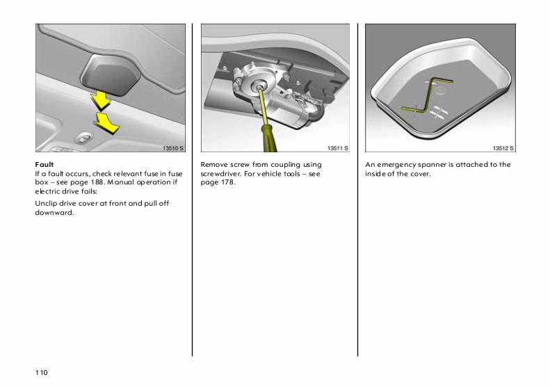
110
Fault If a fault occurs, check relevant fuse in fuse box – see page 188. M anual op eration if e lectric drive fails:
Unclip drive cover at front and pull off downward.
Remove screw from coupling using screwdriver. For vehicle tools – see page 178.
An emergency spanner is attached to the insid e of the cover.

111
Place screwdriver part of emergency spanner at m ark on side of coupling and extract coupling. If coupling cannot be extracted, insert emergency spanner into drive and sla cken by turning forwards a nd backwards.
Insert hexagon side of emergency spanner into hexagon socket and turn to close roof.

126
Easytronic
The semi-autom atic Ea sytronic transm ission permits manual (manual mode) or automatic gear shifting (automatic mode), both with fully automatic clutch control.
Transmission display The current gear or mode is indicated in the transm ission display .
Selector level positions Selec tor lever in N Neutral.
The engine can only be started with the lever in position N a nd with the foot brake depressed . The transmission display shows "N" . If the foot brake is not depressed, "N" flashes.
Selector lever in centre positionWhen the selec tor lever is moved from N to the mid position w ith the foot brake depressed, Easytronic is in Automatic mode and first gear is engaged. The transmission displa y show s "A" . When the foot brake is released, the vehicle begins to "c reep ". If the foot brake is not depressed, "A" flashes. Press the accelerator pedal directly to drive away or return the selector lever to N and repeat the process with the foot brake depressed.
In Automatic m od e the transmission shifts to other gears autom atically dependent on driving c onditions.
Disreg ard of these instructions may lead to injuries or end ang er life.

127
In Manual m od e the gea rs can be shifted manually. The transm ission displa y shows the c urrently engaged gear.
If the eng ine speed is too low the Easytronic will a utoma tica lly shift to a lower gea r even in Manual mode. This prevents the engine from stalling.
Selector lever in + or - + Shift to a higher gear.
- Shift to a lower gear.
If a higher gear is selected when the running speed is too low, or a lower g ear when the speed is too hig h, no shift is effected. This prevents the engine from running at too low or too high revs.
Gears ca n be skipp ed b y jogging the selector lever repea tedly at short intervals.
When the vehicle is in Automatic m ode, Ea sytronic shifts to Manua l mode when the selector lever is set to position + or -. The transm ission display shows the currently selected g ear.
Selec tor lever in A/MSwitch between Automa tic and Manual mode.
Selec tor lever in RReverse gear. Engage only when the vehicle is stationary. Press the button on the selector lever and select R. The tra nsmission display will show "R".
If R is selected when the vehic le is in motion, "R" flashes in the transm ission display and no g ear is eng aged.
Electronically controlled driving programm es in automatic mode z By m eans of delayed gear cha nging
(higher engine speed s) following a cold start, the opera ting temperature programme quickly and automatically bring s the catalytic converter to the temperature required for optimum pollutant reduction.
z Adaptive programmes autom atically adapt gear shifting to suit the d riv ing cond itions, suc h as if the vehic le is tow ing a caravan/trailer, ha s a hig h payload, or is being driven on inclines.

128
Winter programm e T In the event of diffic ulties starting off on slip pery road s, p ress button T ("A" and T are shown in the tra nsmission display). Ea sytronic switches to Automatic mode and the vehicle sets off in second gea r.
The w inter program is switched off by : z pressing button T a gain, z switching to Manual mode z turning off the ignition.
In order to protect the Easytronic the winter programme automatically sw itches itself off at extremely high clutch temperatures.
Kickdown Ac celera tor pedal pressed past the pressure point: Below certain speeds, the tra nsmission shifts down into a lower gear. Full engine power is a vailable for acceleration.
During kickdown no manual gear shifting is possible.
When the engine speed approaches its up per limit, the transm ission shifts to a higher gea r during kickdown even in Manua l mode.
Without kickdown this automatic shift is not effected in Manual mode.
Engine braking assistance frommotor Autom atic mode:When driving d ow nhill, Ea sytronic does not shift into the higher gea rs until a relatively high engine speed has been reac hed. When brak ing, Easytronic shifts down into a lower gear in good time.
Ma nua l mode:To utilize the engine braking effect, select a lower gear in good time when driving downhill.

129
Stopping the vehicle When the selector lever is in the mid position and the vehicle at a standstill, first gear (second gear with active sta rting-off aid) is automatically engaged and the clutch opened.
If a warning signal sound s w hen the driver’s door is opened (foot brake not depressed), m ove the selector lever to N and ap ply the ha nd brake.
When stopping on gradients engage hand brake or depress brake ped al. To prevent overheating of the automatic clutch, do not increase engine speed to ensure smooth id ling while standing if a gear is enga ged.
Switch off eng ine if stop ping for a lengthy period, e.g. in traffic jams or at level crossings.
Vehicle storageBefore leaving the vehicle: z eng age hand brake,z rem ove ignition key.
The last gea r engaged is retained. When the selector lever is in position N no gea r is engaged.
When the ignition is switched off the Easytronic no longer responds to movem ent of the selector lever.
If the ignition key is not removed, the battery m ay be discharged if the vehicle is then left to stand for a lengthy period of tim e.
If the hand b ra ke has not been applied , the control indicator R flashes for a few second s a fter the ignition is switched off.
Rocking the car If it becomes necessary to rock the vehicle to free it from sand, m ud , snow or a hole, move the selector lever between the mid position a nd R in a repea t pattern while simultaneously applying light p ressure to the accelerator ped al. Do not race the eng ine and avoid sudd en acceleration.
This applies only to the exceptional circumstances mentioned above.

130
Manoeuvring the vehicle To manoeuvre the vehicle back and forth during attem pts to park or in garage entrances the creeping movement can be utilized by releasing the foot brake.
Never actuate a ccelerator and brake pedals simultaneously.
In order to protect Easytronic, it automatically disengages the "creep func tion" a t extremely high clutch tem peratures.
Fault If a fault occurs in Easytronic , control indica tor A lights up . In the event of serious faults, an "F" also appears in the tra nsmission display.
It is possible to continue driving if only warning lig ht A lights up . Manual mode can then no longer be selected.
If an "F" is also shown in the transmission display , it is not possible to continue driving.
Have the ca use of the fault rem edied. We recommend that you consult your Vauxhall Authorised Repairer. The system’s integrated self-diag nostics a llows faults to be q uick ly remedied.
Interruption of power supply The clutch is not disengaged if the vehicle battery is d ischarged and a gea r has been selected. The vehicle c annot m ove.
If the battery is fla t, sta rt the vehicle using jump leads – see pa ge 170.

131
If the c ause of the interruption to the p ow er sup ply is not the discharged battery , consult a workshop. We rec om mend consulting your Vauxhall Authorised Repairer. If the vehicle has to be rem oved from moving traffic, relea se clutch as follow s:
1. Ap ply hand brake and switch off ig nition.
2. Open bonnet and engage support.
3. C lean Easytronic around the cap (see figure) so that no dirt can get into the opening w hen the ca p is removed.
4. Rotate cap to slacken and remove by lifting upwards – see figure.
5. Turn the a djusting screw clockwise using a flat-head screwdriver (vehicle tools – see page 178) until clear resistance can be felt. The clutch has now been disengaged.
Do not turn beyond the resista nce, since this can damag e the Easytronic.
6. Fit cleaned cap again. The cap m ust be in full conta ct with the housing.
Towing the vehic le and starting the eng ine is not perm itted when the clutch has been released in this way, although the vehicle can b e m oved a short distance.
Contact a workshop immediately. We recommend that you consult your Vauxhall Authorised Repa irer.

132
Automatic transmission 3
After sta rting the engine and before shifting into a gea r, depress the brake pedal. If the brake peda l is released when a gea r is eng aged , the vehicle will "c reep ". Never depress the ac celera tor and brake pedals simultaneously .
Once D has been selected, the economy driving p rogra mme is operative. Position D is g enerally ideal for d riv ing.
If the accelerator peda l is depressed gently and evenly the transmission w ill shift into the fuel-saving gears at an early stage. The drive ra nge needs be changed manually only in exceptional c ases. Select 3, 2 a nd 1 only when automatic shifting up is to be avoided or if additional use is to be made of the engine braking effect.
Select D ag ain as soon as driving conditions perm it.
Transmiss ion display The current selector lever position is shown in the tra nsmission display in the tachometer.
Failure to follow the description can lead to injuries or endanger life.

133
Selector lever in P, R and N P Park. Front wheels locked.
Enga ge only when the vehicleis stationary and the hand b ra ke isapplied.
R Reverse. Only engage whenvehic le stationa ry .
N Neutra l.
The selector lever can only be moved from the P position with the ignition switched on and the foot brake operated (selec tor lever lock).
To engage P or R pull release under selector lever.
The engine can only be started with lever in position P or N. When position N is selected, press foot brake or engage hand brake before starting.
Do not a ccelerate d uring the selection proc edure.
Drive ranges D, 3, 2, 1 D Position for normal driving
cond itions in 1st to 4th gea r.
3, 2, 1 The transm ission does not shiftbeyond the selected gear.
To select 3 or 1 pull ha ndle beneath selector lever.
After the engine has been started and D selected, the economy driving programme is always operative.

134
Electronically controlled driving programmes z Sporty programm e: Tra nsmission shifts
at high engine speeds:Ta p button S (1 illuminates in the transmission display).
z Economy p rogram me: Transmission shifts a t lower engine speeds: Ta p button S again.
z Winter prog ra m: Press T button.
z Automatic neutral shift function automatically sets the transmission to N to reduc e fuel consumption, e.g. at traffic lights.
The automa tic neutral shift isactiva ted if: – selector lever is in D, 3, 2 or 1
and– the foot brake is operated
and– the vehicle is stationary
and– the accelerator is not being operated.
As soon as the brake is released and the accelerator pedal is depressed, the vehicle starts off in the usual m anner.
z By mea ns of delayed gear changing (higher eng ine speeds) following a cold start, the operating tem perature programm e quickly and automatically brings the ca ta lytic converter to the temperature required for op tim um pollutant reduction.
z Adaptive programm es automatically adap t gea r shifting to suit the driving conditions, such as if the vehicle is towing a c aravan/trailer, has a high pay loa d, or is being driven on inclines.
Winter program me T In the event of difficulties starting off on slippery roads, press button T, which can be opera ted in P, R, N , D and 3 (T illuminates in the transmission display). The vehicle starts off in third gea r.
The winter program is switched off b y: z pressing b utton T again, z shifting to 2 or 1 m anua lly ,z turning off the ignition.
The winter programme automatically switched off a t speeds in excess of app rox . 50 mph (80 km/h).
The winter programme automatically switches off at extremely high transmission oil temperatures in order to prevent dam age.

135
Kickdown Accelerator pedal pressed past the pressure point: below certa in speeds, the transm ission shifts down into a lower gear. Full engine power is availab le for acceleration.
Engine braking assistance frommotor In order to utiliz e the eng ine braking effect when driving downhill, select d rive range 3, 2 or, if necessary, 1 in good time.
The braking action is most effective in drive range 1. If drive range 1 is selected at too high a speed, the transm ission remains in second gear until the shift p oint for first gear is reached, e.g. as a result of deceleration.
Rocking the car If it becomes necessary to rock the vehicle to free it from sand, mud, snow or a hole, move the selector lever from D to R in a repeat pattern w hile sim ultaneously applying light pressure to the accelerator pedal. Do not race the engine and avoid sudden acceleration.
This applies only to the exceptional circum stances mentioned a bove.
Manoeuvring the vehicle To ma noeuvre the vehicle back and forth during attempts to park or in ga ra ge entrances, the vehicle’s creeping movement can be utilised by releasing the brake pedal.
Never actuate accelerator and brake pedals sim ultaneously.
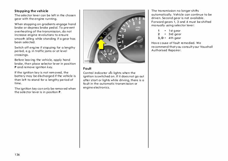
136
Stopping the vehicle The selector lever can be left in the chosen gear with the engine running.
When stopping on gradients engage hand brake or depress brake ped al. To prevent overheating of the transmission, do not increase engine revolutions to ensure smooth id ling while standing if a gear has been selected.
Switch off eng ine if stop ping for a lengthy period, e.g. in traffic jams or at level crossings.
Before leav ing the vehicle, apply hand brake, then place selector lever in position P and remove ignition key.
If the ignition key is not rem oved, the battery may be d ischarged if the vehicle is then left to stand for a lengthy period of time.
The ignition key ca n only be removed when the selector lever is in position P.
Fault Control indica tor A lights when the ignition is switched on. If it does not go out after start or lights while driving, there is a fa ult in the automatic transm ission or engine electronics.
The tra nsmission no longer shifts automatically. Vehicle can continue to be driven. Second gear is not available. Forward gears 1, 3 and 4 must be shifted ma nually using selector lever:
1 = 1st g ear 2 = 3rd gear 3, D = 4th gear
Have c ause of fault remedied. We recommend that you consult your Vauxhall Authorised Repa irer.
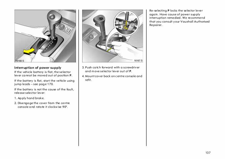
137
Interruption of power supply If the vehicle battery is flat, the selector lever ca nnot be moved out of position P.
If the battery is flat, start the vehicle using jump leads – see pag e 170.
If the battery is not the cause of the fault, release selector lever:
1. Ap ply hand brake.
2. Disenga ge the cover from the centre console a nd rota te it clockw ise 90°.
3. Push ca tc h forward with a screwdriver and m ove selector lever out of P.
4. Mount cover back on c entre console and refit.
Re-selecting P locks the selector lever aga in. Have cause of power sup ply interruption remedied . We recommend that you consult your Vauxhall Authorised Repairer.

112
Climate control
Dep ending on how the vehicle is equipped , the c lim ate w ill be controlled by a heating and ventilation system with optiona l air conditioning system 3 or by a clima te control system 3.
Heating and ventilation system with optional air conditioning system 3 Ventilation, heating and cooling 3 a re combined into one unit that is d esigned to prov ide com fort regardless of the season, weather or outside temperature.
When cooling 3 is activated, the air is cooled and dried.
The heating unit heats the air a s required in all operating m od es depending on the position of the temperature switch. The air supply can be adjusted to suit requirements by means of the fan.
Button n for cooling and 4 for recirculation are only found on vehic les equipped with the optional air conditioning system 3. See pa ge 114.
Electronic air conditioning system 3 The electronic air conditioning system provides maxim um comfort under any weather conditions, at any outside temperature and at a ll tim es of the year.
To ensure a constant and com fortable climate in the vehicle, the temperature of the inflowing air, the air-flow rate and the air distribution are changed a utomatically acc ording to clim atic conditions outside the vehicle.
C lim ate c ontrol system – see page 119.

113
Heater controls Left -hand rota ry switch: Temperature red zone = warmblue zone = cold
Centre rotary switch: Fan Four speeds: x Off 4 Maximum air flow
The rate of air flow is determined b y the fa n. The fan should therefore a lso be switched on during a journey.
Rig ht-hand rotary swi tch: Air distribut ion V to the windscreen and
front door windows
J to the windscreen, front doorwindows and to foot well
K to foot w ell
L to head area a nd to foot w ell
M To head a rea
Open the air vents when the switch is set to L or M.

114
Heated rear window 3,heated exterior mirrors 3 Operation with ignition switched on:
On = Press ÜOff = Press Ü again
Control indicator in pushbutton.
Air conditioning system 3Air recircula tion system 4 Air recirculation button 4 is used to switch the air conditioning system to air recirculation mode (control indicator).
If fum es or unpleasant odours penetrate from outside: tem pora rily sw itc h on a ir recirculation system 4 .
The air recirculation system minim ises the entry of outside air. The humidity increases, and the windows can mist up. The qua lity of the passenger compartment air deteriora tes which may cause the vehicle occupants to feel d row sy.
Switch the a ir distribution to V: the air circulation system is a utoma tica lly shut off to provide faster dem isting of the windows.
Cool ing n The cooling unit (AC compressor) of the air conditioning system is activated using switch n (control indica tor). Operation with cooling is only possible if the engine is running and the fan is on.
When the cooling unit is on, the air is cooled and dehum id ified. Switch off cooling to conserve fuel whenever cooling or dehum idifica tion is not required.
At low outsid e temperatures the cooling unit sw itc hes off a utomatica lly .

115
Centre and side (1) air vents Pleasant ventilation to the head area controlled by the position of the tem perature switch. Temperature sw itch in the m id position: Cooler air flows from the centre vents than from the side vents.
The a ir flow can be directed as desired by tilting and swivelling the sla ts.
To close the vents, p ush the slider towards the centre of the vehicle.
To increase the air supply , set the fan to a higher sp eed.
Windscreen defroster nozzles (2 ) Air distribution switch set to V or J:Air is directed onto the windscreen and the door wind ow s.
Additional vents Located in front of the wind screen, in front of the door windows and in the front foot wells.
Heated seats 3 Two buttons ß in the centre console; operational for the respective front seat when the ignition is switched on.
On = Press ßOff = Press ß again
Control indicators in the pushbuttons.
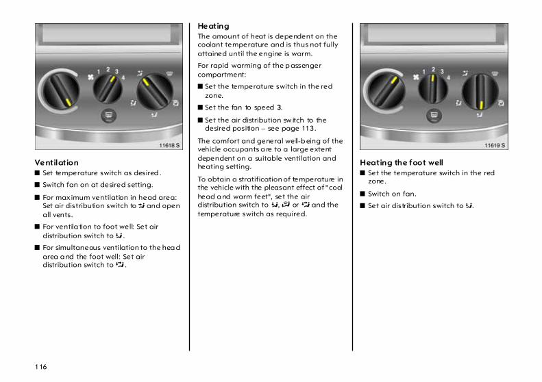
116
Ventilation z Set temperature switch as desired .
z Switch fan on at desired setting.
z For maximum ventilation in head area: Set air distribution switch to M and open all vents.
z For ventila tion to foot well: Set air distribution switch to K .
z For simultaneous ventilation to the hea d area a nd the foot well: Set air distribution switch to L .
Heating The amount of heat is dependent on the coolant temperature and is thus not fully attained until the engine is warm.
For rapid warming of the p assenger compartment:
z Set the temperature switch in the red zone.
z Set the fan to speed 3.
z Set the air distribution sw itch to the desired position – see page 113.
The comfort and general well-b eing of the vehicle occupants a re to a large extent dependent on a suitable ventilation and heating setting.
To obtain a stratification of temperature in the vehicle with the pleasant effect of "cool head a nd warm feet", set the air distribution switch to K, J or L and the temperature switch as required.
Heating the foot well z Set the temperature switch in the red
zone.
z Switch on fan.
z Set air distribution switch to K.

117
Demisting and defrostingthe windows
z Turn the temperature switch as far into the red zone as possib le,
z Set fan to 3 or 4,
z Set air distribution sw itch to V,
z Switch on the heated rear window 3,
z Direct the side air vents a s required towa rd s the door windows.
z For simultaneous w arming of the foot well, set air distribution switch to J.
Operation of the system 3Comfort sett ing
z Air rec irculation system 4 off,
z Set cooling n as desired,
z Set temperature switch a s d esired,
z Sw itch on fan at desired level of air flow,
z Set air distribution switch to M or L,
z Open vents as required.
Temperature switch in centre of adjustment range: Warmer a ir will flow into the foot well a nd cooler air into the upp er zone, with warm er air coming from the side air vents and cooler air from the c entre vents.
Ma xim um cooling (Max imum A ir Conditioning) Open w indows and sun roof 3 briefly so that warm air can esca pe rap idly.
z Air circulation system 4 on.
z Cooling n on.
z Turn the temp erature switch as far into the blue zone (cold) as possible.
z Set fa n to 4.
z Set air distribution switch to M.
z Open all vents.
Disreg ard can cause the windows to become misted up , which can lead to accidents due to lack of proper vision.

118
Window dem istingWind ow m isting e.g. during d amp wea ther or with dam p clothing:
z Cooling n on,
z Set temperature switch as desired ,
z Switch on fan at desired level of air flow,
z Air d istribution switch to V, air recirculation system 4 automatically switches off,
– or –
if there is still moisture in the system after previous air c onditioning operation, the windows may mist up. To prevent this, set air distribution to K before sta rting eng ine and set to V approx. 5 sec onds after starting.
Window de-icing
z Cooling n off,
z Set temperature switch as desired,
z Set fa n to desired speed ,
z Air distribution switch to V, air recirculation system 4 automa tic ally switches off,
z Open sid e air vents.
Operation with cooling (AC comp ressor) is not possible when outsid e temperatures are low.
Note see page 124.
Maintenance see page 125.
Disregard can cause the wind ow s to become misted up, whic h can lead to accidents due to lack of proper v ision.

119
Autom atic climate control system 3 The electronic air conditioning system provides maximum comfort under any weather conditions, a t any outsid e tem perature and at all tim es of the year.
To ensure a constant and com fortable climate in the vehicle, the tempera ture of the inflowing air, the air-flow rate a nd the air distrib ution are cha nged automatically according to clim atic conditions outside the vehicle.
Temperature changes d ue to external influences, such as direct sunlight, are autom atic ally compensated.
When the cooling unit (AC compressor) is on, the air is cooled and dehum id ified.
When no c ooling or dry ing is required press the ECO button to save fuel – see page 122.
When set to automa tic mode, the automatic climate control system p rov ides the op tim al settings for a lmost all conditions. If necessary, a utomatic clima te control system settings can be modified ma nually.
The autom atic climate control system is only operational when the engine is running.
At low outsid e temperatures the cooling unit (AC comp ressor) switches off automatically.

120
Autom atic m ode Basic setting for max imum comfort:
z Press AUTO button.
z Open all air vents.
z Switch on AC com pressor – see page 122.
z Preset tem perature to 22 °C with turn knob .
If nec essary , the pre-selected tem perature can be set higher or low er.
Deactivating the AC c om pressor (ECO appea rs in the air conditioning display) may restric t the level of c om fort and safety. See pag e 122.
All air vents are regulated automatically in autom atic mode. The a ir vents should therefore always be open. See pag e 115.
Pre-selected tem peratures The preselected tem perature ca n b e set to va lues between 16 °C and 28 °C using the left-hand rotary knob.
For the sake of comfort, only change the pre selec ted temperature in small steps.
If a temp erature b elow 16 °C is set, LO app ears in the air cond itioning display : the automatic c lim ate control system runs consta ntly with maxim um cooling. The temperature is not regulated.
If a temp erature a bove 28 °C is set, HI app ears in the air cond itioning display : the automatic c lim ate control system runs consta ntly with maxim um heating. The temperature is not regulated.
The preset temperature is retained when the ignition is switched off.

121
Manual sett ings Under certain circumstances (e.g. iced or misted wind ow s), the functions of the automatic clima te control system can be modified manually.
Manual settings are stored when the ignition is switched off.
Make ma nual settings as follow s w hen necessary:
Wind ow demist ing and d e-icing
Press button V. V appears in the air conditioning display.
The tem perature, air distrib ution and fan are set automatically, windows are quickly demisted and de-iced
To return to autom atic mode: Press button V or AUTO.
Heated r ear window ,heated exter ior mirror s 3 Heating operational only w ith engine running.
Press button Ü . Ü appears in the air conditioning display .
The rear window a nd exterior mirrors w ill quickly be cleared of ice and cond ensa tion.
Heating is switched off a utomatica lly after app rox . 15 m inutes. To switch it off before that time: Press button Ü again.
Disregard can cause the wind ow s to become misted up, whic h can lead to accidents due to lack of proper v ision.

122
AC compressor activation/deact ivatePress the ECO button. ECO appears in the air conditioning display .
Switch on to save fuel. In this mode cooling (AC com pressor) is switc hed off.
Inflowing air is neither cooled nor dehumid ified. This restricts the level of comfort provid ed by the autom atic clima te control system. This may cause the windows to mist up, for example.
To return to opera tion with cooling: p ress the ECO button. ECO d isappears.
Air distribution Press one or more of the following buttons. The corresponding symbol app ears in the air conditioning display:
s: Air distribution to windscreenand front side windows.
M: Air distribution to vehicle occupantsvia adjustable air vents.
K: Air distribution to foot w ell.
To return to autom atic mode: press the appropriate buttons ag ain, or press AUTO.
Air flow Set air flow using the right-hand rotary knob. The selected fan speed is indicated by the number of bars.
To deactivate the fan and thereby the climate control system: Turn the right rotary knob antic lockwise until the display goes out.
To activa te: Turn the right-hand rotary knob c lockwise.
To return to automatic m ode: press the AUTO button.

123
Air reci rculation systemThe a ir recirculation system prevents the entry of outside air and the air in the passenger com partment is circulated .
Press button 4 . % appears in the air conditioning d isplay .
The exchange of fresh air is reduced in air circulation mode. The quality of the passenger com partment a ir deteriorates which may cause the vehicle occupants to feel drowsy. In op eration without c ooling the a ir humid ity increases, so the wind ow s may mist up. Conseq uently , the air circulation system should only be run for short periods of tim e.
To switch off a ir recirculation: Press button 4 again.
Air condit ioning wi th the eng ine not running When the vehicle is stop ped and the ignition off, the heat or cooling power still in the system can b e used to condition the passenger compa rtm ent, for example when stop ped at a level crossing.
Press AUTO with the ignition off. The preselected temperature appea rs in the air conditioning display. The temperature can be a djusted with the left-ha nd rotary knob.
The air conditioning will operate for a limited period of tim e.
To deactivate air conditioning, press the AUTO button.

124
Air intake The air intakes in front of the wind screen on the far left and right-hand sides of the engine compartment must be kept free of lea ves, d irt and snow.
Air outletDo not cover the air outlets when storing item s in the luggage com partment storage compartments.
Pollen filter The pollen filter cleans the air entering from outside and filters dust, soot, pollen and spores from the interior air if the air recirculation system 3 is active. The active carbon layer 3 e liminates m ost odours a nd ha rm ful a mbient ga ses from the air.
The pollen filter must b e replaced at the intervals specified in the Service Booklet.
Note If the windsc reen is misted due to damp weather, temporarily set the system as desc ribed under "Wind ow dem isting".
Cooling 3 functions most efficiently when the wind ow s a nd sun roof 3 are closed. If the passenger compa rtm ent has heated up considerably after a long period in direct sunlight, briefly open the windows and sun roof 3 so that the hot air can esca pe q uick ly .

125
When cooling 3 (AC compressor) is switched on, c ondensation forms, which is expelled from the underside of the vehicle.
At lea st one air vent must b e open while cooling 3 (air conditioning compressor) is on in order to prevent the evaporator from icing up due to lack of air movement.
For trouble-free operation of the automatic climate control system 3, d o not c over the sensor between the air vents in front of the windscreen.
Maintenance In order to ensure consistently good op eration, the AC compressor 3 m ust be switched on for severa l minutes once per month irrespective of the weather or time of year. Op eration with cooling (AC compressor) 3 is not possib le when outside temperatures are low .
If a fault occurs, consult a w orkshop. We recommend your Vauxhall Authorised Repairer.

138
Driving hints
The first 600 miles (1000 km) Drive your vehicle at various speeds. Do not use full throttle. Never allow the eng ine to labour at low revs.
Make good use of all gea rs. Depress the accelerator pedal a maximum of around three quarters of the ava ila ble ped al travel in all gears.
Do not drive faster than three quarters of max imum speed.
Do not brake unnecessarily hard for the first 125 miles (200 km ).
Never coast with engine not running Many units w ill not function in this situation (e.g. brake servo unit, power steering 3 ). Driv ing in this ma nner is a danger to yourself and others.
Brake servo unit When the engine is not running, the brake servo unit is no longer effective once the brake peda l has been depressed once or twice. Braking effect is not reduced , but significantly greater force is required for braking.
Power steering 3 If the power-assisted steering fails when being towed with the engine switched off, the vehicle can still be steered, but considera bly more forc e is req uired.
Driving in mountainous terrain or with a trailer/caravan The cooling fan is electrically operated. Its cooling p ow er is therefore independent of the engine speed.
Since a considerable amount of heat is genera ted at high engine speeds and less at slower speeds, do not shift d ow n when climbing hills whilst the vehicle is still coping with the gradient in the higher g ear.
Diesel engines: On gradients of 10 % or more, do not drive fa ster tha n 20 mph (30 km/h) in first gea r or 30 mp h (50 km/h) in second gea r.
Driving with a roof load Do not exceed the perm issible roof load – see page 234. For reasons of safety, distribute the loa d evenly a nd secure it properly with reta ining straps so that it cannot slip. Adjust ty re pressure to the load conditions. Do not d rive fa ster than 75 mph (120 km /h). Check and retighten the straps freq uently .
Switching off the engine When you switch off, fans in the eng ine compa rtm ent may continue running for a time to cool the engine.
If the engine temperature is very high, e.g. after driving in mountainous terrain: Allow the engine to id le for approx im ately two minutes in order to prevent heat acc um ulation.
Vehicles with turb ocharged engine After running at high eng ine speeds or high eng ine loads, op erate the engine briefly at a low load or run in neutral for approx. 30 seconds before switching off in ord er to protec t the turbocharger.

139
Save energy – more miles Please observe the running-in hints on the previous pag e and the tips for energ y saving on the following pages.
Good, technica lly correct and economical driving ensures ma ximum durability and performance for your vehic le.
Overrun The fuel supply is autom atically shut off during overrun, e.g. when the vehicle is being driven down long gradients or when braking. To enable the overrun cut-off to take effect, do not acc elerate during overrun and, if in manual transm ission mode, do not de-clutch. To prevent dam age to the cata lytic converter, overrun cut-off is temp orarily deactivated when the catalytic converter temperature is high.
Vehicles w ith turb ocharged engine Flow -g enerated noises may be aud ible if the a ccelerator is released quickly on account of air flow in the turbocharger.
Engine speed Drive in a low engine speed range for each gear a s m uc h as possible.
Warming up Allow the engine to warm up while driving. Do not warm it up by letting it run at idling speed. Do not apply full throttle until the engine has reached op erating temperature.
After a cold start, the automatic tra nsmission 3 a nd Easytronic 3 do not shift into higher gears until higher engine speeds have been reached. This allow s the catalytic converter to quickly reac h the temperature required for optimum pollutant reduction.
Correct gear selection Do not race your engine whilst in neutral or with a low gea r selected. Driving too fast in indiv idua l gea rs as well as stop-a nd -g o tra ffic increases engine wear a nd fuel consumption.
Change down When decreasing speed, shift down into the next lowest gear. Do not slip the clutch with a high-revving engine. This is especially important when hill climb ing.
Clutch operation Always d epress the c lutch pedal hard to the floor to p revent shifting difficulties and transmission damage.
When driving do not use the pedal as a foot rest; this will cause substantial clutch wear.
PedalsDo not place any ob jects in the foot well which could slip under the ped als and inhibit the pedal travel.
To ensure the pedal travel is uninhibited, there must be no mats in the area of the pedals.
Battery care When driving slowly or when the vehicle is stationary , e.g. in slow urban traffic, stop-and-go traffic or traffic jams, turn off all unnecessary electrical load s w here possible (e.g. heated rear window, heated front seats, etc. ).
Declutch w hen sta rting in order to relieve the strain on the starter and the ba ttery.

140
Saving fuel,protecting the environment
Trend-setting technologyWhen developing and manufac turing your vehic le, Vauxhall used environment-friendly and in the m ain recyc la ble materials. The production methods used to make your vehicle are likewise env ironmenta lly -compatible.
Recycling of production wastes keeps the circulation of material closed. Reduction of energy a nd water requirements a lso help s to conserve natural resources.
A highly advanced design mea ns that your vehic le can be easily disassembled at the end of its working life, and the individual materials separated for subsequent re-use.
Materia ls such as asbestos and cadmium are not used . The refrigerant in the air conditioning system 3 is CFC-free.
New painting techniques employ wa ter as a solvent.
End-of-life vehicle recovery Information on end-of-life vehicle recovery centres and the recycling of end-of-life vehicles is available at www.Vauxhall.co.uk.
Energy and environment-conscious driving z High noise levels and exhaust em issions
are often a result of driving w ithout due attention to saving energy and protecting the environment.
z You should therefore drive with energy in mind – "more miles with less fuel" .
Reduce the noise level and exhaust emissions b y adopting an environment-consc ious driving style. This is extremely worthwhile and im proves the quality of life.
Fuel consum ption d epend s to a great extent on your own personal d riv ing style. The following hints are intended to help you consume fuel at a rate that is as close as possible to the specified levels – see page 231.
Check your vehicle’s fuel consumption every time you refuel. This facilitates early detection of any irregula rities causing increased fuel consumption.
Warming up z Full throttle and w arming up at idle
speed increase w ear, fuel consumption, exhaust em ission, the am ount of pollutant in the exhaust and the am ount of noise.
z Drive off imm ediately after starting. Wa rm up the engine b y running it at moderate eng ine speeds.
Uniform speed z Hectic driving significantly increases fuel
consumption, the exhaust emissions, the proportion of pollutant in the exhaust gas and the noise level.
z Do not accelerate a nd brake unnecessarily . Drive at uniform speed, watching the road.
Avoid frequent starting off and stopping e.g . at traffic lights, in short distance tra ffic and in queues of traffic by m eans of clever planning . Select road s w ith good traffic flow .
Idling z The eng ine also consumes fuel when
idling .
z If you have to wait for more than one minute, it is worthwhile switching off the engine. Five m inutes of idling corresponds to ap prox imately one kilometre of driving.

141
Overrun z The fuel supply is automatically shut off
during overrun, e.g. when the vehicle is being driven down long gradients or when braking – see page 139.
z To enable the overrun cut-off to come into action and save fuel, do not accelerate or d eclutch during overrun.
Correct gear selection z High revs increase engine w ear and fuel
consumption.
z Do not race your engine. Avoid d riv ing at high engine speeds.
Making use of the tachom eter helps to save fuel. Drive in a low engine speed ra nge for each gear as much a s possible with uniform engine speeds. Drive as often as possible in top gear, select the next higher gear a s soon as possible, and only chang e down when the engine is no longer running perfectly smoothly .
High speed z The higher the speed , the higher the
consumption and the noise level. At top speed, you consume a great deal of fuel and produce excessive noise and exhaust em issions.
z Slightly relea sing the accelerator ped al results in distinct fuel savings with no major loss of speed.
Drive at no more tha n around three quarters of max imum speed and you will use up to 50 % less fuel, without losing a great deal of time.
Tyre pressure z Inadequate ty re p ressure, leading to
higher road resistance, costs m oney in two wa ys: for more fuel and increased tyre wear.
z Regular checks (every 14 d ays) pay off.
Electrical loadsz The power consum ption of electrical
equip ment increa ses fuel consumption.
z Sw itch off all aux iliary electrical loads (e.g. air c onditioning 3, heated rear window) when not needed.
Roof racks, ski-holders z Due to air resistance, a roof load can
increase fuel consump tion by approx. 3.5 gal/1000 m iles (1 l/100 km ).
z Remove them if they are not being used.
Repair and maintenance z Improper repairs or adjustm ent and
maintenance work can increase fuel consumption. Do not carry out w ork on the eng ine yourself.
You may out of ignorance infringe environmental law s b y not disposing of materials properly.
Appropriate parts might not b e recycled.
Contact with some of the materia ls involved may p ose a hea lth haz ard.
z We recom mend that repair and maintenance be entrusted to your Vauxhall Authorised Repairer.
Extreme driving conditionsz Going up steep slopes, cornering, driving
on poor road s a nd winter driving a ll increase fuel consumption.
Fuel consumption increa ses dramatically in urba n tra ffic a nd at winter temperatures, especially on short trip s when the engine operating tempera ture is not reached.
z Follow the hints given above to keep consumption to a m inimum under suc h cond itions.

142
Fuel consumption,fuel, refuelling
Fuel consumption Fuel consump tion is determined und er specific driv ing conditions – see page 231.
Special equipment increases the weight of the vehicle. As a result, they can increase fuel consump tion and reduce the specified maximum speed.
There is increased friction betw een engine and transmission parts during the first 1000 kilometres. This increases fuel consump tion.
Fuel for petrol engines Commercially available high-quality fuels a re suita ble (cata lytic converter – see p age 144, octane numbers – see pages 228, 229). Fuel quality has a dec isive influence on the power output, running behaviour and serv ice life of the engine. The additives contained in the fuel play an important role in this regard. You should therefore only use high-q uality fuels containing add itives.
Fuel with too low an octane number can cause pinking. Vauxhall cannot be held lia ble for resulting dama ge.
Petrol with a higher octane number can always be used.
Pump noz zles for lead ed fuel cannot be inserted into the filler neck of vehicles that op erate on unleaded fuel.
The ignition tim ing is a utoma tica lly adjusted according to the grade of fuel used (octane number) – see pages 228, 229.
Use of petrol w ith a n oc ta ne rating of 95 will ensure economica l driving.
Fuel for diesel engines Diesel engines m ust be operated only on comm ercially available diesel fuel meeting the specifications of DIN EN 590. Do not use m arine diesel oils, heating oils or entirely or partially plant-based diesel fuels, such as rape seed oil or bio diesel, Aquazole and similar diesel-water emulsions.
The flow and filterability of diesel fuel a re temperature-dependent.
Diesel fuels with improved low-temperature properties a re therefore available on the market during the winter months. Make sure that you fill the tank with winter fuel before the start of the cold weather season.
Additives can be used with diesel fuels with winter prop erties that are guaranteed by the manufa cturer and when using diesel fuel filters that are heated depending on the outside temperature.

143
Fuel fil ler cap If the fuel filler cap must be replaced, use only the Genuine Vauxhall fuel filler c ap designed for your model to ensure that full func tionality is retained. Vehicles with diesel engine ha ve a sp ecial fuel filler cap.
Refuelling
Fuel filler neck at right rear sid e of vehicle.
On Corsas eq uipp ed with a centra l lock ing system 3, the tank flap is unlocked together with the doors – see pag e 54.
Open the tank flap . To prevent dam age, the right-hand sliding door cannot be fully op ened if the tank flap is op en.
To unloc k the fuel filler cap, unlock with the ignition key 3 , unscrew and susp end from tank flap.
The fuel tank has a limiting system which prevents overfilling of the tank.
Correct filling depends to a la rg e extent on prop er operation of the fuel dispensing pump:
1. Fully insert the pump nozzle and switch it on.
2. After the automatic cut-off, the nominal capacity of the tank ca n be obtained by top ping up with two doses of fuel. Make sure the nozzle is fully inserted.
To c lose, place fuel filler cap in position and turn, overcom ing the resistance until the ratchet on the cap engages audibly. Lock the fuel filler cap with the ignition key 3.
C lose fuel tank cover.
Wipe off a ny overflowing fuel immediately .
Care must be taken when handling fuel.
Before refuelling , switch off the engine Switch mobile phones off. Petrol is flam mable and explosive. Please therefore avoid na ked fla mes and sp arks when handling fuel, even when you are in the v icinity of fuel. Do not smoke! This also applies in places where petrol can only be detected by its cha ra cteristic smell. If you can smell petrol in the vehicle, have ca use thereof remedied immed iately. We recommend that you consult your Vauxhall Authorised Repairer.

144
Catalytic converter, exhaust gases
Catalytic converter for petrol enginesLeaded fuel will da mage the cata lytic converter and parts of the electronic system, rend ering them inoperative.
Use of high-qua lity fuels other than those specified on p age 142 (e.g. LR P1)) could damage the catalytic converter.
On vehicles with a c atalytic converter, the fuel ta nk filler nec k is of a narrow design so that a dispensing pump for leaded fuel cannot b e inserted .
Dama ge to the catalytic converter or the vehicle m ay result if the following points are not observed :
z Consult a workshop, such as your Vauxhall Authorised Repairer, as quic kly as possible in the event of misfiring, irregular engine running following a cold start, a significant loss of engine power or other unusual malfunctions which may indica te a fa ult in the ignition system. If necessary, d riv ing may be continued for a short time at a low speed and with a low engine speed.
Irregular engine running a nd a loss of engine power when the Traction Control System 3 or the Electronic S tability Program 3 com e into action are determined b y the op erating conditions and are therefore of no significance – see pages 148, 149.
z If unb urnt fuel enters the c atalytic converter, this may result in overheating and irreparable damage to the c atalytic converter.
You should therefore avoid unnecessarily long use of the starter when setting off, running the tank dry (an erratic fuel supply leads to overhea ting) and starting the engine by pushing or towing.
1) LRP = Lead Replacement Petrol.

145
z If the emission control indicator Z flashes, slow down until the flashing stops a nd the control indicator is steady. Conta ct a workshop immediately . We recommend your Vauxhall Authorised Repairer. Em ission control ind ic ator Z – see pa ge 146.
Catalytic converter for diesel engines Damage to the ca talytic converter or the vehicle may result if the follow ing points are not observed:
z Consult a workshop, such a s your Vauxhall Authorised Repairer, as quickly as possible in the event of irregular eng ine running, a sig nificant loss of eng ine power or other unusual malfunctions. I f necessary, driving may be continued for a short tim e a t a low speed and with a low engine speed.
Irregular engine running and a loss of eng ine power when the Traction Control System 3 or the Electronic Stability Program 3 come into ac tion are determined by the opera ting conditions and a re therefore of no sig nificance – see pages 148, 149.
Controlling exhaust emission Throug h design-rela ted measures – mainly in the a rea of the fuel-injection and ignition systems – the proportion of nox ious ma terials in the exhaust, such as carbon monoxide (CO), hydrocarbons (HC) a nd nitrogen oxides (NOx), is reduced to a minimum.

146
Control indica tor Z for exhaust Lights up w hen the ignition is switched on and during the start a ttempt. Goes off shortly after the engine starts running.
If it lights while the engine running there is a fault in the emission control system. The permitted emission values may b e exceeded. Consult a workshop immediately . We recomm end your Vauxhall Authorised Repairer.
Flashing with the engine running indicates a fault that may damage the catalytic converter. You can continue to drive without causing damage by slowing down until the fla shing stop s and the control indica tor is stead y. Consult a workshop immed iately. We recommend tha t you consult a Vauxhall Authorised Repairer.
Control indic ator A for eng ine electronics Lights up for a few second s when ignition is switched on.
If the light comes on when the eng ine is running, there is a fault in the engine or transmission electronics. The electronics switch to the emerg ency running programm e, fuel consumption ma y increa se and the driveability of the vehicle ma y be affected. In some cases the fa ult can b e eliminated b y switching the engine off and ba ck on again. If the control indicator lights up again when the engine is running, consult a workshop to have the cause of the fault eliminated. We recommend your Vauxhall Authorised Repairer.

147
If it lights briefly, but does not recur, it is of no sig nificance.
If it flashes w hen the ignition is on there is a fault in the imm obiliser system – see page 51.
Exhaust gases
When the vehicle is driven for the first tim e, wax a nd oil on the exhaust system may evap orate, producing sm oke. After driving the vehicle for the first time, allow it to stand in open air to allow the fum es to evap orate and d o not inhale.
Maintenance Have a ll maintenance work carried out at the intervals sp ecified by Vauxhall. We recommend that you entrust this work to your Vauxhall Authorised Repairer, who has proper equipment and trained personnel a vailable. Electronic testing systems permit rapid diagnosis and remedy of faults. This way you can b e certain that all com ponents of the vehicle’s electrical, injection a nd ignition systems operate correctly, that your vehicle ha s a low level of pollutant emission a nd that the catalytic converter system will have a long service life.
You are thereby making an im portant contribution towards keeping the air clean and c om pliance w ith emissions legislation.
Checking and adjustment of the fuel-injection and ignition systems is part of the scope of inspec tion. For this reason you should have a ll maintenance work carried out a t the intervals specified in your Serv ice Booklet.
Engine exhaust gases contain poisonous carbon monoxide, which is colourless and odourless and could be fatal if inhaled.
If exhaust fumes penetrate the vehicle interior, open the windows and consult a workshop immediately . We recommend that you consult a Va uxhall Authorised Repairer.

148
Drive Control Systems
Traction Control System (TCPlus) 3 The TCPlus prevents the driving wheels from spinning, irrespective of the road conditions and tyre grip.
The system monitors the rotational speed of all wheels. As soon as at least one driving wheel starts to spin, the eng ine output is reduced (the sound of the engine changes) a nd the spinning wheel is braked. This im proves the vehicle’s directional control and driving power, particularly on snow and ice as well a s on wet or slippery roads.
TCPlus is ready for operation as soon as the ignition is switc hed on and the warning lig ht v g oes out.
When the TCPlus c om es into action, v flashes.
The vehic le is now in a critical situation; TCPlus a llows you to keep control of the vehicle and remind s you to match your speed to the road c onditions.
Control ind icator v Lights up for a few seconds when ignition is switched on. The system is now ready for op eration.
Flashing during drivingThis shows the system has come into action. The engine output ma y be reduced (the sound of the engine changes) and the vehicle may be braked automatically to a sma ll degree.
Lights w hile driving Fault in the system: Driving can continue. Spinning drive wheels can cause d riv ing stability to worsen unless driving style is ada pted, depending on acceleration and road surface.
Have the cause of the fa ult remedied. We recommend that you consult your Vauxhall Authorised Repa irer. The system’s integrated self-diagnostics allows faults to be quickly remedied .
Do not let this special safety fea ture tempt you into ta king risks when d riv ing.
Traffic safety c an only be achieved by adopting a responsible driving style.
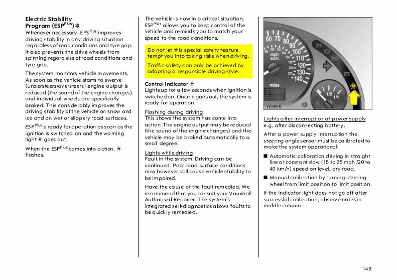
149
Electric StabilityProgram (ESPPlus) 3 Whenever nec essary , EPSPlus imp roves driving stability in any driving situation reg ardless of road conditions and tyre grip. It also prevents the d rive wheels from spinning regard less of road conditions and tyre grip.
The system monitors vehicle m ovements. As soon as the vehicle starts to swerve (und ersteers/oversteers) engine outp ut is red uced (the sound of the engine changes) and individual wheels are specifically braked. This considerably im proves the driving stability of the vehicle on snow and ice and on wet or slipp ery road surfaces.
ESPPlus is ready for operation as soon as the ignition is switched on and the wa rning light v goes out.
When the ESPPlus comes into a ction, v flashes.
The vehic le is now in a critical situation; ESPPlus allows you to keep c ontrol of the vehicle and remind s you to match your speed to the road c onditions.
Control ind icator v Lights up for a few seconds when ignition is switched on. Once it goes out, the system is ready for operation.
Flashing during drivingThis shows the system has come into action. The engine output ma y be reduced (the sound of the engine changes) and the vehicle may be braked automatically to a sma ll degree.
Lights while driv ingFault in the system. Driving ca n be continued. Poor road surface conditions may however still cause vehicle stability to be im paired.
Have the ca use of the fault rem edied. We recommend that you consult your Vauxhall Authorised Repairer. The system’s integrated self-diag nostics a llows faults to be q uick ly remedied.
Lights a fter interruption of p ow er supplye.g. after disconnecting battery .
After a power supply interrup tion the steering angle sensor must be calibrated to ma ke the system operational:
z Automatic calibration d riv ing in straight line a t consta nt slow (15 to 25 mph /20 to 40 km /h) speed on level, dry road.
z Manual calibration by turning steering wheel from limit position to limit position.
If the indicator light does not go off after successful calibration, observe notes in midd le column.
Do not let this special safety fea ture tempt you into ta king risks when d riv ing.
Traffic safety c an only be achieved by adopting a responsible driving style.
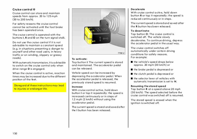
150
Cruise control 3 Cruise control can store and maintain speeds from approx. 20 to 125 m ph (30 to 200 km/h).
For safety reasons the cruise control cannot be activated until the foot brake has been operated once.
The c ruise c ontrol is operated with the buttons I , R and O on the turn signal stalk.
Do not use the c ruise control if it is not adv isable to maintain a c onstant sp eed (e.g. in situations presenting a danger to yourself and other road users, in heavy traffic or on winding , slippery or greasy roads).
With autom atic transmission, it is a dvisa ble to switch on the cruise control only when drive range D is engaged.
When the cruise control is active, reaction times may be increased due to the different position of the feet.
To activate: Ta p button I: The current speed is stored and maintained. The acc elera tor p edal can be released.
Vehicle speed ca n be increased by depressing the a ccelerator peda l. When the accelerator pedal is released, the previously stored speed is resumed.
Increase With cruise control active, hold down button I or tap it repeatedly: the speed is increased c ontinuously or in steps of 1.2 m ph (2 km/h) without using the accelerator ped al.
The current speed is stored and saved a fter the I button has been released.
Decelerate With cruise control a ctive, hold down button R or tap it repeatedly : the speed is reduc ed c ontinuously or in steps.
The current speed is stored and sa ved after the R button ha s b een relea sed.
To deact ivate: Tap button O : The cruise control is switched off. The vehicle slowly decelerates. To continue driving, dep ress the accelerator ped al in the usua l way.
The cruise control switches off automatically under certa in driving conditions for safety reasons.For example:
z the vehicle’s speed drops belowapprox. 20 mp h (30 km/h) or
z the brake pedal is depressed or
z the clutch pedal is dep ressed or
z the selector lever of vehicles with autom atic transmission is set to N.
Resuming the stored speed Tap button R at a speed a bove 20 mph (30 km/h): The speed selected before the cruise control w as switched off is resumed.
The stored speed is erased when the ignition is switched off.
Disreg ard of these instructions may lead to injuries or end ang er life.

151
Parking distance sensor 3 Park distance sensor ma kes reverse parking easier by measuring the distance between the rear of the vehicle a nd an obstacle through ultrasonic reflection a nd warning you with an a coustic signal in the passenger com partment.
The system record s the distance using four sensors in the rear bumper.
When the ig nition is on, Parking distance sensor switches on automatically when reverse g ear is enga ged. Its operational rea diness is indicated by a brief acoustic signa l.
If the vehicle slowly gets close to an obstacle w hile reversing, an intermittent acoustic signal is audible in the passenger compartment when the vehicle tail is less than one m etre from the obstacle. The interval between the signals becomes shorter as the distance is reduced. If the distance is less than 30 c m, a continuous signa l is aud ible.
Fitting rear load racks 3 Rear load racks, e. g. bicycle ra cks, fitted nea r the sensors could disrupt the system .
Fault In the event of a system fault, a continuous acoustic signal is sounded at a dista nce of one metre from the obstacle. Have the cause of the fault remedied . We recommend that you consult your Vauxhall Authorised Repa irer.
In order to avoid operationa l problems or erroneous information, the sensors m ust be undamag ed a nd free of soiling, snow and ice.
Under certain circumstances, various reflective surfaces on objects or clothing as well as external noise sources may cause the system to fail to d etec t obstacles in the rear. For this reason, care must be taken when reversing even if Pa rk ing distance sensor is op erational. This is of pa rticular im portance when in the vicinity of pedestria ns.

156
Wheels, tyres
Tyres See page 243 for suitable tyres a nd restrictions.
Tyres fitted in the factory are a dapted to the c hassis a nd provide optimum driving comfort and safety .
Changing tyre/wheel typeBefore changing to tyres or w heels of a different size, seek ad vice as regards tec hnical possibilities. We recom mend that you consult your Vauxhall Authorised Repairer, who will be aware of any necessary chang es.
If tyre of a size d ifferent than those mounted at the factory are mounted, the electronic speedometer m ay need reprogramming in order to ensure that the speed disp la y is correct.
Fit ting new tyres Fit ty res in pairs or in sets, which is even better. Ensure that tyres on one axle are z the sam e size z the sam e desig n z the sam e ma ke z and have the sam e tread pa ttern.
Fit directional tyres such tha t they roll in the direction of travel. The rolling direc tion is indica ted b y a sym bol (e.g . an arrow) on the sidewall.
Tyres fitted op posing the rolling direction (such as when changing a tyre) should be refitted as soon as possible. This is the only way to b enefit fully from the design prop erties of the ty re.
Som e brands of ty res have a beaded edge for alloy w heels to protec t against dam age. If wheel covers are used on steel wheels with beaded-edge tyres, the following procedure must be followed:
z Use of wheel covers and tyres that are approved by Vauxhall a nd fulfil all requirem ents for the wheel/tyre combination.
z If the wheel c overs and tyres used are not Vauxhall-approved, the tyres m ust not have a bea ded edge.
Use of unsuitab le tyres or wheels m ay lead to accidents and render the vehicle unroa dworthy .
We recommend that you have your ty res chang ed b y your Vauxhall Authorised Repairer, who will b e familiar w ith the requirem ents of the law a s regards disposal of tyres and can thus help to protect the environment and your health.
Use of unsuitable tyres or wheel covers could lead to sudden pressure loss and thereby accidents.

157
Tyre pressure Check ty re pressures, including the spare wheel, at least every 14 days and prior to any long journey; the ty res should be checked when cold. Don’t forget to check the spare.
Use the valve cap key to make unscrewing the valve caps easier. The key is located on the inside of the tank flap.
Tyre pressure – see pa ge 243 and the adhesive foil on the insid e of the fuel tank flap. H ave adhesive foil replaced after changing to different tyre size.
Do not reduce tyre pressure when the ty res are warm. Otherwise the pressure m ay drop below the permissible minim um when the ty res cool down.
After having checked the ty re p ressures, tighten the valve caps using the valve cap key.
Incorrect infla tion pressures will imp air safety, vehicle handling, comfort and fuel economy and will increase tyre wear.
If the pressure is too low, this can result in considera ble ty re warm -up and internal damage, leading to trea d separation and even to tyre blow-out at high sp eeds.
Hidden tyre d amage is not eliminated by adjusting inflation p ressure.
Tyre condition, wheel condition Drive over edges slowly and at a right angle if possible. Driv ing over sharp edg es can lead to hidd en tyre damage and wheel dam age which is only noticed later on.
When p arking, ensure that the tyres are not pressed against the edge of the kerb.
Check ty res regularly for d amage (foreign bodies, punctures, cuts, cracks, bulges in sidewa lls). Check wheels for dam age. In the event of damag e or ab normal wear, consult a workshop. We recommend your Vauxhall Authorised Repairer.
Incorrect ty re p ressure can lead to tyre rupture.
Damage may lead to tyre blow-out.

158
Tread depth Check tread depth regularly.
Should the front tyres show greater wear than the rear tyres, ha ve both front wheels exchanged with the rear wheels so that the tyres w ith deeper tread are on the front axle.
Correct tyre pressure.
For reasons of safety, tyres should be rep la ced when their tread depth has worn down to 2 to 3 mm (winter tyres: 4 mm).
The leg ally permissible minimum trea d depth (1.6 mm) has been reached when the tread has worn down as far as one of the wear indicators (TWI1)). A number of wear indicators are sp aced at eq ual intervals around the tyre within the trea d. Their position is indicated by m arkings on the tyre sid ewall.
General information
z The risk of aq ua planing is greater if the tyres are worn.
z Tyres age, even if they a re used only very little or not at all. A spare wheel which has not b een used for six years should be used only in emergencies; drive slowly when using suc h ty res.
z Never fit used tyres the previous history and use of which you do not know.
z So as not to impair b ra ke cooling, use only wheel trims approved for use on your vehicle.
Tyre d esigna tions Meaning s:
e.g. 155/80 R 13 79 T
155 = Tyre width in mm 80 = Aspect ratio
(ty re height to tyre width in %) R = Belt type: Radial 13 = Wheel d ia meter in inches 79 = Load ind ex
e. g.: 79 corresponds to 437 kg T = Speed cod e
Speed code letters:
Q Up to 100 mph (160 km /h) S Up to 112 mph (180 km /h) T Up to 118 mph (190 km /h) H Up to 130 mph (210 km /h) V Up to 150 mph (240 km /h) W Up to 168 mph (270 km /h)
1) TWI = Tread Wear Indicator.
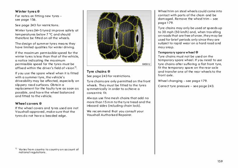
159
Winter tyres 3 For notes on fitting new tyres – see page 156.
See page 243 for restric tions.
Winter tyres (M+ S tyres) im prove safety at tem peratures below 7 °C and should therefore be fitted on all the wheels.
The d esign of summ er tyres mea ns they have limited qualities for winter driving.
If the maxim um perm issible speed for the winter ty res is less than that of the vehicle, a notice ind icating the ma ximum permissible speed for the tyres must be affixed within the driver’s field of v ision1).
If you use the spare wheel when it is fitted with a summer tyre, the vehicle’s driveability may be affected, espec ia lly on slip pery roa d surfaces. Ob ta in a rep la cement for the faulty ty re as soon a s possible, and have the wheel balanced and fitted to the vehicle.
Wheel covers 3 If the wheel covers and tyres used are not Vauxhall-approved , make sure that the tyres d o not have a bea ded edge.
Tyre chains 3 See pag e 243 for restrictions.
Tyre chains are only p ermitted on the front wheels. They must be fitted to the tyres symmetrically in order to a chieve a concentric fit.
Alw ays use fine mesh chains that add no more than 15 m m to the ty re tread and the inboard sides (including chain lock).
We rec om mend that you consult your Vauxhall Authorised Repairer.
Wheel trim on steel wheels could come into contact with parts of the cha in and be dam aged . Remove the wheel trim – see pag e 179.
Tyre cha ins may only be used at sp eeds up to 30 mph (50 km/h) and, when travelling on roads that are free of snow , they m ay be used for brief periods only since they are subject to rap id wea r on a hard road a nd ma y sna p.
Tempora ry spar e w heel 3 Tyre chains must not be used on the temporary spare wheel. If you need to use tyre chains after suffering a flat front tyre, fit the temporary spa re on the rear ax le and transfer one of the rea r wheels to the front axle.
Wheel changing – see pag e 179.
Correct tyre pressure – see pa ge 243.
1) Varies fro m country to country o n account of national regulations .

152
Brakes Brake system The brakes are a n important factor for tra ffic safety .
To improve effectiveness, do not brake unnec essarily ha rd for the first 120 miles (200 km) after new brake p ads ha ve been fitted.
Brake pad wear must not exceed a specified lim it. Reg ular maintenance as detailed in the Service Booklet is therefore of the utmost im porta nce for traffic sa fety.
Have w orn b ra ke p ads replaced. We recommend that you consult your Vauxhall Authorised Repa irer, who will fit pa ds that have been tested and a pproved by Vauxhall and guarantee optim um braking power.
Brake pad s that have worn down to the minimum thic kness will squeal. Driving may be continued. H ave the brake pad s replaced as soon as possible. Consult a workshop for brake pad replacement. We recommend your Vauxhall Authorised Repairer.

153
Brake servo unit When the brake peda l is q uick ly and forcefully depressed, the vehicle is automatically braked with ma ximum b ra ke force a mplification in order to obtain the shortest possib le brak ing distance during full-on bra king (brake servo unit).
Maintain the p ressure on the brake pedal for as long as full-on braking is required. Max imum brake force amplification is deactivated as soon as the brake ped al is released.
Foot b rake The foot brake comp rises two independent brake circuits.
If a brake circuit fails, the vehicle can still be braked using the other brake circuit. If this oc curs, however, the brake pedal m ust be depressed quite far using considerable force before braking effect occurs. The distance required for braking will b e greater. Consult a workshop before continuing your journey. We recomm end your Vauxhall Authorised Repairer.
To ensure the full pedal travel can be utilized, esp ecially in c ase of a fault in one of the brake circuits, there must be no mats in the vicinity of the peda ls – see p age 139.
When the engine is not running, the support of the brake servo unit disap pears once the brake pedal has been depressed once or twice. Braking effect is not reduc ed, but braking requires signific antly greater force. This is especially im portant to bear in mind w hen towing .
Check the brake lights before starting out on a journey.
Shortly a fter sta rting each journey the effectiveness of the brake system should be tested at low speed a nd without inconveniencing other traffic, especially if the brakes are wet, e.g. a fter the vehicle has been washed.
The brake fluid level should be checked regula rly . If the brake fluid level is too low and the ha nd brake is not applied, control indicator R on the instrument panel lights up – see page 32.

154
Hand brake Always apply hand brake firm ly. On slopes apply the hand brake as firmly as possible.
The m echanical hand b ra ke a cts on the brakes on the rea r wheels. It engag es automatically when applied.
To relea se the ha nd b ra ke pull the lever up slig htly , press the ratchet knob, a nd fully lower the lever.
Brake system c ontrol indic ator RThe control indica tor lig hts when the ignition is switc hed on if the ha nd brake is applied or if the brake or clutc h fluid level is too low. Brake fluid – see page 216.
ABS u 3 The Anti-lock Brake System (ABS) continuously monitors the vehicle’s brake system and prevents the wheels from locking regardless of the road condition and tyre grip.
It starts to regulate the braking pressure as soon a s a wheel shows a tendency to lock. The vehicle rema ins steerable, even in the event of very heavy braking, for insta nce on bends or when swerving to a void an obstacle. Even in the c ase of full-on brak ing, the ABS makes it possible to drive round an obstacle w ithout releasing the brakes.
ABS control is mad e ap parent thoug h a pulse in the brake pedal and the noise of the regulation process.
If the control indicator lights when the hand brake is not applied: S top. Interrupt your journey immediately. Consult a workshop. We recommend your Vauxhall Authorised Repairer.

155
Control ind icator u for ABSWhen the ignition is switched on, the control indicator lights for a few second s while the system performs a self-check, whic h ma y be audible. The system is ready for operation when the control indicator goes out.
If the control indicator does not go out after a few seconds, or if it lights up while driving, there is a fault in ABS. The vehicle’s brake system rem ains operational without AB S reg ulation.
You can continue driving, provided you drive with care and anticipation.
Have the cause of the fa ult remedied. We recommend that you consult your Vauxhall Authorised Repa irer. The system’s integrated self-diagnostics allows faults to be quickly remedied .
For optimum b ra king, keep the brake pedal fully depressed throughout the braking process, despite the fac t tha t the p edal is pulsating. Do not reduce the pressure on the pedal.
Do not let this special safety feature tempt you into taking risk s when driving.
Traffic safety can only be achieved by adopting a responsib le driving style.
If there is a fault in ABS, the wheels m ay be sub ject to locking due to braking tha t is heavier than normal. The a dvantages of AB S are no longer opera tional. The vehicle may sw erve.

160
Roof racks, caravan and trailer towing
Roof racks 3 For reasons of safety and to avoid damaging the roof, we recommend that you use the Vauxhall roof rack system approved for your vehicle. Consult your Vauxhall Authorised Repairer.
Disenga ge c overs concealing roof rack mounts by pushing sliders in direc tion of arrow (e.g. with coin) and remove. To close roof rack mounts, insert covers at front a nd engage slid ers at rear.
Fasten the roof ra ck follow ing the instructions the a ccompany the system.
Driv ing hints – see pa ge 138.
Towing equipment 3 Always use trailer towing equipment that is app roved for the vehicle. We recommend that you entrust retrofitting of tow ing equipment to your Vauxhall Authorised Repairer, who will be able to provide inform ation about possible towed load increa ses. The Vauxhall Authorised Repairer has instructions on how to install the tow ing equipment and any possible modifications to the vehicle that affec t the cooling system or other equipment.
Retrofitting of towing equipm ent is not possible for vehicles with Parking distanc e sensor.
For installation dimensions of the trailer towing equipment – see pages 251, 252.
Disregard of these notes can lead to injuries whic h may be fatal. Vehicle passengers should be informed accordingly.
When operating without a trailer, remove the coupling b all bar.

161
Towing equipment with rem ovable coupling ball bar 3 , Corsa Stow age of coupl ing bal l bar The c oupling ba ll bar is fastened benea th the sp are wheel in a b ag next to the vehic le tools.
Fit ting the coupl ing bal l bar Remove the sealing plug from the hole for the coupling ball ba r and stow it away in the luggage compartment.
Tensioning coupling ball bar: hold safety slider 1 at top a nd b ottom, pull ba ckwards as far as possible and hold. Push release lever 2 to the left.
6

162
Insert coupling ball b ar into housing of coupling using a little pressure until it audibly engages.
Pull coupling ball bar to chec k that it is engaged.
If coupling ball bar is correctly enga ged
z the red fie ld on release lever 2 will not be visible,
z and release lever 2 can be pushed no more than 5 mm toward the coupling ball b ar.
Repeat procedure if coupling ba ll ba r does not engage.
Press red button. Put on protective cap and eng age.

163
Red button must spring up when safety cap engages. Check that protective cap is firmly sea ted.
Imp or tant Tra iler operation is only permitted if
z coupling ball b ar is correctly engaged ,
z and protec tive cap has been put on and eng aged.
Eye for break-awa y stopp ing cab le For carava ns/trailers with brake, attach the break-away stopp ing cable to the eye to the right of the coup ling ball bar; see arrow in figure.
Towing a c aravan/trailer is only permitted w ith a properly attached coupling b all bar. If the coup ling ball bar cannot be properly attached, consult a workshop . We recommend that you consult your Vauxhall Authorised Repairer.
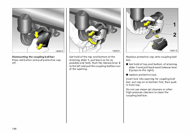
164
Dismounting the coupling b all ba r Press red b utton and p ull p rotective cap off.
Get hold of the top and bottom of the retaining slider 1, pull bac k as far as possible a nd hold. Push the release lever 2 to the left and pull the coupling ball ba r out of the opening.
Replace protective cap onto coupling ball bar:
z Get hold of top and bottom of retaining slider 1 and pull backward (relea se lever 2 jump s to the right),
z replace protective ca p.
Insert lock into opening for coupling b all bar: put cap on a t bottom first, then push in from top.
Do not use steam -jet cleaners or other high-pressure clea ners to clean the coupling ball b ar.

165
Stow age of coupl ing bal l barPlace the coupling ball b ar in the ba g as shown on pa ge 161 in fig. 11755 S and attach next to the vehicle tools beneath the spare wheel.
Towing equipment with fixed coupling ball bar 3 , Combo In the case of trailers/caravans with b ra ke, attach break-away stop ping cable to eye to right of coupling ball bar.
Caravan and trailer loads1)
The permissible caravan/trailer loads are vehicle- and eng ine-dependent m aximum values which must not be exceed ed. The actual caravan/trailer load is the difference between the actual gross weight of the caravan/trailer and the actual coupling socket load with the caravan/trailer coupled. When the carava n/trailer load is being checked, therefore, only the caravan/trailer w heels – and not the jockey wheel – must be standing on the weighing apparatus.
The permissib le caravan/trailer load s for your vehicle are given in the vehicle documents. Unless otherwise stated, they are valid for g ra dients up to max. 12%.
The permissible c aravan/trailer load should be fully utilised only by drivers w ho a re adequately exp erienced in tow ing large or hea vy ca ravans/trailers.
6
1) Obs erve national regulatio ns.

166
The p ermissible caravan/trailer load applies up to the specified incline and up to an altitude of 1000 m etres above sea level. Since engine power decreases as altitude increases because the air becomes thinner (thereb y reduc ing climbing ability), the permissible tow ing weight also decreases by 10% for every 1000 metres of additional altitude. The towing weight does not have to be reduced when driving on roads with slig ht inclines (less than 8%, e. g. motorways).
The actual caravan/trailer load plus the actual gross vehicle w eight must not exc eed the m aximum p ermitted towing weight. For example, if the permitted gross vehicle weig ht is utilised, the trailer/caravan load must only b e used until the maximum permitted towing weight is reached . The maximum permitted towing weight is shown on the id entific ation p la te – see page 226.
Coupling socket load The coupling socket load is the load exerted by the trailer/caravan on the coupling ball. It can be va ried by changing the weight distribution when loading the trailer/caravan.

167
The ma ximum permissible coup ling socket load (50 kg) is specified on the towing equipm ent identification plate and in the vehic le documents. Alw ays aim for the maximum load, especia lly in the ca se of heavy caravans/trailers. The c oupling soc ket load should never fall below 25 kg.
When mea suring the coup ling socket load, make sure that the drawbar of the loa ded trailer/caravan is at the sa me height as it will be when the trailer/caravan is coupled with the towing vehicle load ed. Particularly important for trailers/caravans w ith tandem axle.
Rear axle load during towing Corsa saloonWhen the caravan/trailer is coupled and the towing vehic le fully loaded (including all occupants), the perm issible rear ax le loa d (see identification plate or vehicle docum ents) may be exceeded by 45 kg and the permissible gross vehicle weight by 15 kg. If the permissib le rear axle load is exc eeded, a maximum speed of 60 mph (100 km/h) a pplies. If national regula tions specify a low er ma ximum speed for vehicles towing a caravan/trailer, this must be observed.
Corsa deliver y va n, Com bo The permissible axle loads must not be exc eeded.
Tyre pressure Increase tyre pressure on the towing vehicle to the value specified for a full load (see pages 243, 244). Also check the inflation pressure of the spare wheel and the caravan/trailer wheels.

168
Driving characteristics, towing tips For caravans/trailers with brake, a tta ch the break-away stopping cable to the eye (see arrow in figure).
Before attaching the trailer/caravan, lubricate the ball of the trailer/c aravan towing device. However, do not lub rica te the b all if a stabiliser, which acts on the coupling ball, is being used to da mp hunting.
Handling is greatly influenced by the loading of the trailer/caravan. Loads should therefore be secured so that they cannot slip and be placed in the c entre of the trailer/caravan if possible, i.e. above the a xle.
In the case of trailers with low driving stability, do not exceed a speed of 50 mph (80 km /h); the use of a friction-type stabiliser is highly recommend ed.
Check caravan/trailer lighting before starting to drive. The fog tail lights on the vehicle are deactivated w hen towing a caravan or trailer.
Do not d rive faster than 50 mph (80 km/h) if possible, even in countries where hig her speeds are permitted.
Make sure that you ha ve enoug h room when cornering and avoid sudden ma noeuvres.
If the trailer/caravan starts to sway, drive more slowly , do not attem pt to correct the steering and brake sha rp ly if necessary .
The cooling fan is electrically operated. Its cooling power is therefore independent of the engine speed.
S ince a c onsiderab le am ount of heat is generated at high engine speeds and less at slower speeds, do not shift down when climb ing hills whilst the vehic le is still coping with the gradient in the hig her gear.

169
Diesel engine: On rising g ra dients of 10% or more, do not drive faster than 20 mph (30 km/h) in 1st gear or 30 mph (50 km/h) in 2nd gear; with autom atic transmission, d o not exceed 25 mph (40 km/h) in position 1.
When driving downhill, towing a caravan/trailer subjects the brakes to a heavier load than norm al. For this reason, select the same gear as when driving uphill and drive at a similar speed. With automa tic transm ission, engage position 3, 2 or even 1.
Select D again as soon as driv ing conditions permit.
Ea sytronic 3 in autom atic mode or automatic transmission 3 in D will automatically select the driving programme with optimum engine b ra king effect.
If full-on braking is required , depress the brake pedal as hard as possib le.
Remem ber that the braking distance for vehic les towing caravans/trailers w ith a nd without brake is a lways grea ter than that for vehicles not towing a caravan/trailer.
Starting on inclines For vehicles with manual transm ission, the most favourable eng ine speed when starting off on an incline is between 2500 and 3000 rpm for petrol engines and between 2000 and 2500 rpm for diesel engines. Hold engine rp m constant, engage clutch gradually (let slip), release brake and open throttle. If possible, the engine speed should not drop during this proc edure.
On vehicles with Easytronic 3 in autom atic mode or automatic transmission 3 in D, it is sufficient to apply full throttle.
Before starting off under extreme conditions (high combination weight, mountainous terrain w ith steep inclines), switch off all unnecessary electrical loads (e.g. heated rear window, air conditioning system 3, heated front seats 3).

170
Self-help
Diesel fuel system, bleeding Never let the tank run dry! If control indicator Y lights up, refuel as soon as possible. Refuel immediately if it flashes.
It is p ossib le to restart the engine if the ta nk ha s b een run dry . A delayed start is to be exp ected. Sw itc h on the ignition for approx. 40 seconds. Then attem pt to start the engine for approx. 40 seconds. If the engine d oes not start, wait a few minutes and try again. I f the engine does not start, consult a workshop. We recommend your Vauxhall Authorised Repairer.
Do not start with quick charger This prevents damag e to electronic components.
Do not start by pushing or towing Because your vehicle is fitted with a catalytic converter, it must not be started by pushing or tow ing – see page 144.
Starting the engine with jump leads 3 A vehicle with a discha rg ed battery can be started using jump leads and the battery of another vehicle.
z Never expose the battery to naked fla mes or sparks.
z A disc ha rg ed b attery c an freez e at temperatures as low a s 0 °C. Defrost the battery before connecting jum p leads.
z Do not allow battery fluid to come into contac t with eyes, skin, fabrics or painted surfaces. The fluid contains sulphuric acid w hich ca n cause injuries and dama ge in the event of direc t contac t.
z Wear eye protection and protec tive clothing when handling a battery.
Disreg ard of these notes ca n lead to injuries which may be fatal. Vehicle passengers should be informed according ly .
This must be done with extreme care. Any deviation from the following instructions could lead to persona l injury or dam age resulting from b attery explosion, a s w ell as to dam age to the electrical systems in both vehicles.

171
z Use auxiliary battery with sam e voltag e (12 volts). Its capacity (Ah) must not be considerab ly less than that of the discharged battery. Voltage and capacity information can be found on the batteries.
z Use jump leads with insulated terminals and a width of a t least 16 mm 2 (25 mm2 for diesel eng ines).
z Do not d isconnect the disc ha rg ed battery from the vehicle.
z Switch off all unnecessary electrical consumers.
z Do not lean over the battery during jump starting.
z Do not allow the terminals of one lead to touch those of the other lead.
z Do not touch the vehicles w hile jump starting.
z Ap ply hand brake. Transmission in neutra l (automa tic transmission 3 in P, Easytronic 3 in N).
Connect the leads in the order shown in the illustration:
1. Connec t one end of the first jump lead to the positive terminal 1 of the battery providing the jum p start (identified b y "+ " sign on battery case or terminal).
2. Connec t the other end of this lead to the positive terminal 2 of the discharged battery ("+" sig n).
3. Connec t the first end of the other jum p lead to the negative terminal 3 of the battery providing the sta rt ("–" sign).
4. Connec t the other end of the second jump lead 4 to ground on the other vehicle, e.g. engine block or screw connection in the engine suspension.
z Do not connect lead s to negative terminal of discharged battery !
z The connection point should be as far away from the discharged battery as possible.
z Route the leads so tha t they cannot catch on rotating parts in the engine compartment.
z Start the engine of the vehicle prov iding the jump start.
z After 5 minutes, start the other engine. Start attempts should be made at intervals of 1 minute not last longer than 15 seconds.
z After starting, allow both eng ines to idle for approx. 3 m inutes with the leads connected.
z In order to a void excess voltage in the electric al system, b efore removing a lead, sw itc h on a n electrica l consumer (e.g. light, heated rear window) in the vehicle receiving the jump sta rt.
z Reverse above seq uence exac tly when removing leads.
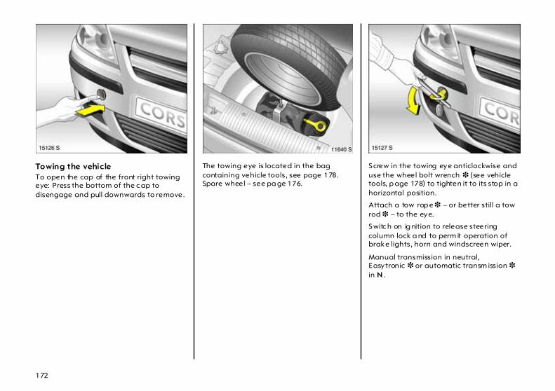
172
Towing the vehicle To open the cap of the front right towing eye: Press the bottom of the c ap to disengage and pull downwards to remove.
The towing eye is located in the bag containing vehicle tools, see page 178. Spare wheel – see pa ge 176.
Screw in the towing eye anticlockwise and use the wheel bolt wrench 3 (see vehicle tools, p age 178) to tighten it to its stop in a horizontal position.
Attach a tow rop e 3 – or better still a tow rod 3 – to the eye.
Switc h on ig nition to release steering column lock a nd to perm it operation of brake lights, horn and windscreen wiper.
Manual transmission in neutral, Easytronic 3 or automatic transm ission 3 in N .

173
Drive slowly . Do not drive jerkily . Excessive tractive forc e ca n damage the vehicle.
Vehicles with automatic transmission 3 should be towed facing forwa rd s only a nd must not be towed faster than 50 mph (80 km/h) or further tha n 60 miles (100 km). If the tra nsmission is defective, or if the above speed or d istance is to be exceeded, the front axle must be raised off the ground .
Consult a workshop. We recom mend your Vauxhall Authorised Repairer, w ho w ill serve you best to get your vehicle ba ck on the road.
If the automatic clutch has been manually relea sed in vehic les with Easytronic 3 because of an interrup tion to the power supply, towing is not permitted – see page 130. In this c ase, consult a workshop as soon as possible. We recommend that you consult your Vauxhall Authorised Repairer.
Towing service Entrust your vehicle only to the towing service of your choice and obtain an estimate on towing costs before employing any tow ing service. In this way you avoid unnecessary c osts and possible insurance problems during claim processing.
Significa ntly g reater force is required for braking: The brake servo unit is only op erational when the engine is running.
Considerably g reater steering force is necessary since this unit is operative only when the engine is running.
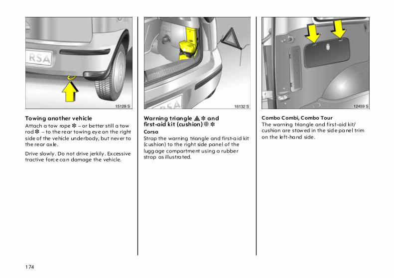
174
Towing another vehicle Attach a tow rope 3 – or better still a tow rod 3 – to the rear towing eye on the right side of the vehicle underbody, but never to the rear ax le.
Drive slowly . Do not drive jerkily . Excessive tractive forc e ca n damage the vehicle.
Warning triangle ¨ 3 and first-aid kit (cushion) + 3 Corsa Strap the warning triangle and first-a id kit (c ushion) to the right side panel of the lugg age compartment using a rubber strap as illustra ted.
Combo Combi, Combo Tour The warning triangle and first-aid kit/cushion are stow ed in the sid e pa nel trim on the left-ha nd side.

175
Release flap by p ressing retaining lugs. Comb o van Plac e the warning triangle and first-aid kit/cushion in the stow age compartment behind the driver’s seat. Disengage the flap 3 by pressing the retaining lug and remove.

176
Spare w heel 3 CorsaThe spare wheel is in the luggage compartment and is secured beneath a floor cover p late using a wing nut. Undo clips beneath the loading sill and lift the floor cover p late.
Comb o The spare wheel 3 is stowed at the rea r underneath the vehicle floor.
1. Fully release the hexagon b olt in the loa d compa rtm ent floor using the wheel bolt wrench. Vehicle tools – see page 178.
2. Lift the spare wheel holder.
3. Unhook the catch and lower the spare wheel.
4. Detach the safety ca ble.
5. Lower the holder fully and take out the spa re wheel.
Vehic les with a temporary spare wheel 3 ha ve a spacer ring between the temporary sp are and the vehic le underbody.
6. Wheel changing – see page 179.

177
7. Place the repla ced wheel in the spare wheel hold er with the outside of the wheel facing upwards.
If a full specification w heel is stow ed, do not fit the spacer ring between the wheel and the vehicle und erbody.
8. Lift the spa re wheel holder, insert the sa fety ca ble.
9. Lift the spare wheel holder and engage in the c atch. The open sid e of the catch must point towards the rear.
10. Turn the hexa gon bolt in the load compartment floor with the wheel bolt wrench to raise the spare w heel holder all the w ay up.
General informationThe spare wheel is d esigned for use as a temporary spa re 3 . The temporary spare is d esigna ted by a sticker on the rim . Follow the instructions on this page and pages 159, 243.
On vehicles with alloy w heels 3 the spare wheel may ha ve a steel rim .
If you use winter ty res 3, the spare wheel may still be fitted with a summ er tyre. If you use the spare wheel the vehicle’s handling may be a ltered. Ob tain a repla cement for the faulty tyre as soon a s p ossible, and ha ve the wheel balanced and fitted to the vehicle.
The spare wheel may be fitted with a sma ller tyre and a sma ller rim than the other tyres on the vehicle: using the spare wheel may alter the handling of the vehicle. Replace a defective ty re as soon as possible, balance the wheel and have it mounted on the vehicle.
Notes on temp orary sp are wheel 3
z Using a temp orary spare w heel may chang e the driving behaviour of the vehicle, particularly if using winter tyres 3 . Replace defective ty re a s quickly as possible, balance wheel and fit to vehicle.
z Mount only one tem pora ry spare w heel.
z Do not drive faster than 50 mph (80 km/h).
z Take curves slow ly .
z Do not use for a lengthy period.
z Replac e temporary spare w heel with full specification wheel without delay.
z Do not use tyre cha ins. I f tyre c hains must b e used when one of the front wheels has a flat ty re, mount the temporary sp are wheel on the rear ax le and transfer one of the rear axle wheels to the front a xle. Check tyre pressure and correct if nec essary . See page 243.
z Note the inform ation on the temporary spa re wheel on pag es 159, 243.

178
Jack £ and vehicle tools CorsaThe jac k and vehicle tools are stowed in a bag underneath the spare wheel in the luggage compartment.
Comb o Comb i, Com bo Tour The jack and vehicle tools are located in a stowage compa rtm ent in the side panel trim on the right-hand sid e.
Release flap by pressing retaining lugs.
The ja ck is secured in place by a wing screw. The vehicle tools are secured to the jack with rub ber ba nd s.

179
Com bo va nThe jac k and vehicle tools are secured behind the driver’s seat.
The jac k is secured in place by a wing screw. The vehicle tools are secured to the jack with rubb er bands.
Changing wheels In order to reduce the chance of possible injuries, m ake the following prepa ra tions and note the procedure:
z Park on a level, firm a nd non-slippery surface.
z Sw itch on haz ard warning lights, apply hand brake, selector lever in P (automatic transm ission 3) / engage 1st gear or reverse (manual transmission or Easytronic 3 ).
z Correctly set up the warning triangle. Warning tria ngle – see page 174.
z Take the spare wheel from the lugg age compa rtm ent or from undernea th the vehicle floor.
z Before raising the vehicle, set the front wheels to the straight-ahead p osition.
z Never change m ore than one w heel at once.
z Block the wheel diagonally opposite the wheel to be chang ed b y placing wedge blocks or equivalent in front and behind the wheel.
z Use the ja ck only to change wheels.
z If the ground on which the vehicle is standing is soft, a solid board (max. 1 cm thick ) should be placed under the jack. Using a thicker board could damage the jack and the vehic le.
z No people or a nima ls m ay be in the vehicle when it is jacked up.
z Never cra wl und er a ja cked-up vehicle.
z Do not start or run the engine while the vehicle is on the jack.
6

180
1. Prise off the hub cap using a screwdriver, positioning the sc rewdriver at the recess at the side of the hub cap. Vehicle tools – see page 178.
Prise off the wheel cover 3 using the hook included with the vehicle tools. Vehicle tools – see p age 178.
Alloy wheels 3: Prise off the hub c ap using a screwdriver, positioning the screwdriver at the recess at the side of the hub cap.
Remove wheel b olt caps 3 from wheel bolts.

181
Alloy wheels w ith a nti-theft lock 3: Release hub cap using key included in vehicle tools and remove it.
2. Slac ken wheel b olts using wheel bolt wrench, p utting on wheel b olt wrench a s far as possible.
3. The jacking p oints on the vehicle underbody are ma rked by depressions on the lower body sill.
6

182
On som e vehicles, the jac king points are concealed by flap s. Fold the flap outwards.
4. Before attaching jack, set to req uired height b y hand. Fit jack arm at front – and rear – in such a w ay that jack claw (arrow in illustration) goes around the vertical ridge and eng ages into the rec ess in the ridge.
When turning the crank , ensure that the edge of the ja ck base on the ground is vertically in line with the contac t point.
If this is not the case when jacking up the vehicle, lower vehicle immediately and reposition the jack.
Raise vehicle b y turning crank handle.
5. Unscrew w heel bolts and put somewhere where the thread s w ill not b e soiled.
6. Change the wheel. For inform ation on the spare wheel – see page 176; for information on the temporary spare wheel – see pages 159, 177, 243.
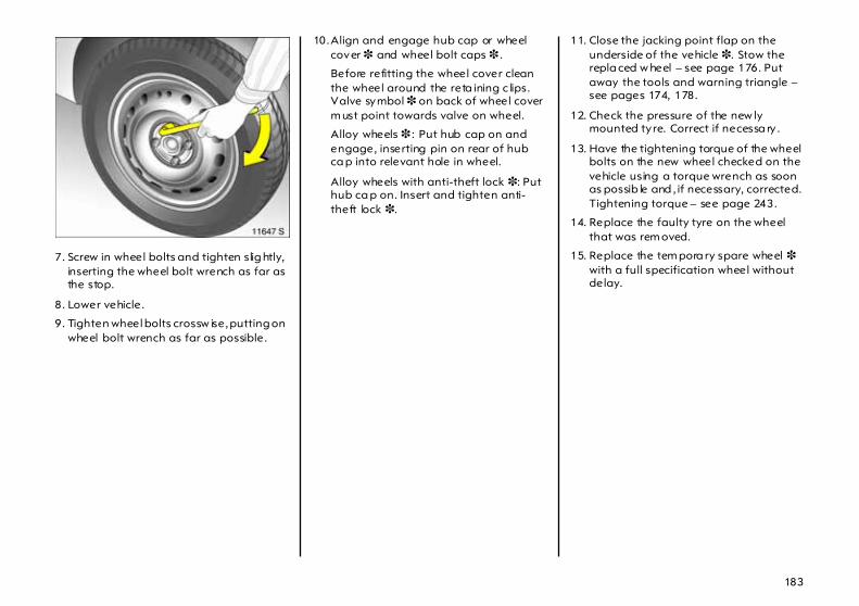
183
7. Screw in wheel bolts and tighten slig htly, inserting the wheel bolt wrench as far as the stop.
8. Lower vehicle.
9. Tighten wheel bolts crossw ise, putting on wheel bolt wrench as far as possible.
10.Align and engage hub cap or wheel cover 3 and wheel bolt caps 3 .
Before refitting the wheel cover clean the wheel around the reta ining c lips. Valve symbol 3 on back of wheel cover m ust point towards valve on wheel.
Alloy wheels 3 : Put hub cap on and engage, inserting pin on rear of hub ca p into relevant hole in wheel.
Alloy wheels with anti-theft lock 3: Put hub ca p on. Insert and tighten anti-theft lock 3.
11. Close the jacking point flap on the underside of the vehicle 3. Stow the repla ced w heel – see page 176. Put away the tools and warning triangle – see pages 174, 178.
12. Check the pressure of the new ly mounted tyre. Correct if necessa ry .
13. Have the tightening torque of the wheel bolts on the new wheel checked on the vehicle using a torque wrench as soon as possib le and , if necessary, corrected. Tightening torque – see page 243.
14. Replace the faulty tyre on the wheel that was rem oved.
15. Replace the tem pora ry spare wheel 3 with a full specification wheel without delay.

184
Tyre repair kit 3 Com bo Minor dam age to the tread and w alls of the tyre by foreign bodies or the like c an be rem edied using the tyre repa ir kit.
Do not rem ove foreign bodies from the tyres.
Damag ed a reas bigger than 4 mm a nd dam age at the tyre rim cannot be repaired using the tyre repair kit.
For important information – see pa ge 187.
If you have a fla t tyre: z Switch on hazard wa rning lights, apply
hand brake, selec tor lever in P (automatic tra nsmission 3) / eng age 1st gear or reverse (manual transmission or Easytronic 3).
z Correctly set up the w arning triangle. Warning triangle – see page 202.
On Com bo Comb i and Com bo Tour, the tyre repair kit is located behind a cover to the left in the sid e trim of the luggage compartment; on the Com bo Va n, it is loca ted in a stowage compartment behind the driver’s seat.
To op en the cover, press to relea se the retaining lugs.
1. Remove bag containing tyre repair kit from compa rtm ent. Carefully remove parts from bag.
2. Remove compressor.
3. Remove electric c onnec ting cable and air hose from stowa ge c om partments beneath compressor.
Driv ing w ith ty re pressure that is too low can cause hidden damage to the tyres. This damag e cannot be remedied using the tyre repair kit. Park vehicle and consult a workshop . We recommend your Vauxhall Authorised Repairer.

185
4. Screw compressor air hose to sealant bottle connection.
5. Press the sealant bottle into the holder on the compressor.
Position the compressor as close as possible to the wheel with the sealant bottle in an upright position.
6. Unscrew dust cap from defective tyre.
7. Sc rew tyre inflation hose to valve.
8. Sw itch on c om pressor m ust be set to § .
9. Plug the c om pressor connec tor into the accessory socket or the ciga rette lig hter socket. Accessory sockets – see page 75.
10. Switch on ignition.
11. Move rocker switch on compressor to I, and tyre is filled w ith sealant.
12. The comp ressor pressure gauge briefly indicates up to 6 bar whilst the sealant bottle is emptying (app rox . 30 seconds). Then the pressure starts to drop.
13. All of the sea la nt is pump ed into the tyre. Then the tyre is inflated.
14. The presc rib ed tyre pressure (see page 243) should b e obtained within 10 m inutes. Switch the compressor off when the pressure is obtained.

186
If the p rescrib ed tyre p ressure is not obtained w ithin 10 minutes, the ty re is too badly damaged. Park the vehicle and contact a workshop. We recomm end your Vauxhall Authorised Repa irer.
Release excess tyre pressure with the button a bove the pressure gauge.
Do not operate compressor for more tha n 10 minutes – see "Important notes" on page 187.
15.Remove the ty re repair kit. Screw the ty re inflation hose onto the free sea la nt bottle connection. This prevents sealant bottle leakage. Stow the tyre repair k it in the lug gage compartment.
16.Remove any excess sea lant using a cloth.
17.Colla pse the warning triangle and stow it in the stowa ge com partment. See pa ge 202.
18.Affix enclosed stic ker indicating m aximum p ermitted sp eed in driver’s fie ld of view.
19.Continue driving immediately so that sea lant is evenly distributed in the ty re. After driving approx. 6 miles (10 km) (but no more than 10 m inutes), stop and check tyre p ressure. Screw com pressor air hose d irectly onto tyre valve when doing this (see Fig. 15798 T).
If tyre pressure is m ore than 1.3 b ar, fill it to the correct value. Repeat the proced ure until there is no more loss of pressure.
If the tyre p ressure ha s d ropp ed b elow 1.3 bar, the vehicle must not be used . Contact a workshop. We rec om mend your Vauxhall Authorised Repairer.
20. Stow the tyre repair k it. See page 184.

187
Im portant
The d riv ing comfort of the rep aired ty re is severely affected, therefore have this ty re rep la ced.
If unusual noise is heard or the compressor becomes hot, turn compressor off for at lea st 30 minutes.
The b uilt-in safety valve opens at a pressure of 7 bar.
Protect comp ressor from moisture and rain.
The sealant can only be stored for approximately 4 yea rs, after w hich time its sealing capability is not longer guaranteed. Pay a ttention to storage information on sealant bottle.
The sealant bottle can only be used once. Replace used sealant bottle.
The compressor and the sealant can be used up to approx im ately -30 °C.
Dispose of used tyre repair kits in accordance with the applicab le laws.
Do not d rive faster than 50 mph (80 km/h).
Do not use for a lengthy period.
Steering and handling may be affected .

188
Electrical system
Fuses A defective fuse can be recog nized b y its melted w ire. A new fuse should only be installed after the cause of the trouble has been rectified.
Fuse box The fuse box is located in the engine compartment next to the coolant exp ansion tank.
Disenga ge c over of fuse box from lug and lift off.
Also remove the cover from over the fuses (marked in yellow in the fig ure).
Elec tronic ig nition system s genera te very high voltag es. Do not touch the ignition system ; high voltage can be fatal.

189
It is advisable to carry a com plete spare set of fuses, obtainable from any Vauxhall Authorised Repairer. Store sp are fuses in the place p rov ided in the fuse box (marked in yellow in the illustration).
To help in replac ing fuses, there is a special fuse-gripping tool on the right-ha nd side in the fuse b ox.
Before replacing a fuse, turn off the respective switch and the ignition.
Slot fuse-gripping tool onto fuse and withdra w it.
Always use fuses with the correct current va lue. This is shown on eac h fuse, and is also indicated by the fuse colour and the plug-in location in the fuse box.
Fuse Fuse
colour ratingGrey 2 A
Brow nish yellow 5 ABrow n 7.5 A
Red 10 ABlue 15 A
Yellow 20 ALight green 30 A
Pink (Maxi-Fuse) 30 AOrange 40 A
Red (M axi-Fuse) 50 AYellow (Maxi-Fuse) 60 A
Black (Max i-Fuse) 80 A

190
Fuses and the most importantcircuits they protectSome circuits m ay be protected by severa l fuses.
The figures on pag es 190, 191 depict the fuse boxes of vehicles w ith engine Z 13 DT1). Fuse boxes of other engines are depicted on pages 192, 193.
1) Sa les designation – see page 229.
Fuse Circuit Rating
1 Central control unit 7.5 A
2 Eng ine control unit 7.5 A
Fuse Circ ui t Rat ing
3 Instruments,information display,light switch,horn,hazard wa rning lights,immobiliser
7.5 A
4 Towing equipment,num ber pla te lights
20 A
Fuse Circuit Rating
5 Electric w indow (left) 20 A
6 Automatic transmission 10 A
7 H eadlight wash system 30 A
8 Starter 10 A
9 Fuel injec tion system,fuel pump,stationa ry heater
20 A
10 H orn 10 A
11 Central control unit 15 A
12 Information display,Infotainment system : engine1) Z 13 DT,Z 17 DTH
20 A
10 A
13 Vauxhall alarm system 7.5 A
14 Exterior m irrors 7.5 A
15 Windscreen wash system
15 A
16 Courtesy light 7.5 A
17 Central control unit 20 A
18 Sun roof 20 A

191
Fuse Circuit Rating
19 Electric window (right)
Eng ine Z 12 XEP1)
with Easytronic:Vauxhall alarm system
20 A
5 A
20 Xenon head lig hts
Eng ine Z 12 XEP1)
with Easytronic:electric window (right)
1) Sa les designation – see page 228.
5 A
20 A
21 Xenon head lig hts 5 A
22 Central control unit,imm ob iliser
5 A
23 Windscreen w ip er 30 A
24 Infotainment system,inform ation display ,light switch,courtesy light,instruments,EPS
5 A Fuse Circ ui t Rat ing
25 Reversing lights, cigarette lighter,accessory socket
Engine Z 12 XEP1)
with Easytronic:brake lights
20 A
10 A
Fuse Circuit Rating
26 Seat heater (right)
Motor Z 12 XEP1)
with Easytronic:automatic tra nsmission,injec tion system,reversing lights,cig arette lig hter,ac cessory socket
15 A
20 A

192
Fuse Circuit Rating
27 Seat heater (left)
Eng ine Z 12 XEP1)
with Easytronic:hea ted seat (rig ht)
1) Sa les designation – see page 228.
15 A
15 A
Fuse Circ ui t Rat ing
28 ABS
Engine Z 12 XEP1)
with Easytronic:heated seat (left)
25 A
15 A
29 Rear wind ow wiper 20 A
Fuse Circuit Rating
30 Engine control unit 15 A
31 Air conditioning system 15 A
32 ABS,Easytronic,automatic tra nsmission,airba g
5 A
33 Petrol engine:Engine control unitDiesel engine:Engine control unit
15 A
7.5 A
34 Diesel filter heater 30 A
35 Sun roof,electric w indow,Infotainment system
5 A
36 Dipp ed b eam (left)
Xenon headlights
10 A
15 A
37 Dipp ed b eam (right)
Xenon headlights
10 A
15 A

193
Fuse Circuit Rating
38 Tail light (left),park ing lig ht (left)
5 A
39 Tail light (right),park ing lig ht (right)
5 A
40 Brake lights,cruise control
10 A
41 Fog lights 15 A
42 Fog tail lights 10 A
43 Main b eam (left) 10 A
44 Main b eam (right) 10 A
45 Ventilation fan 30 A
46 Eng ine control unit 20 A
47 Heated rear w indow 30 A
48 Sta rter 30 A
49 EPS 50 A
50 ABS,TC, ESP
40 A
51 Petrol engine:EasytronicDiesel engine:Eng ine control unit
60 A
80 A
Fuse Circ ui t Rat ing
52 Cooling fan: Petrol engine with air conditioningEngine Z 10 XE,Z 12 XEP1)
without air conditioningEngine Z 14 XE, Z 18 XE1)
without air conditioningDiesel engine
1) Sales designation – s ee page 228.
30 A
20 A
40 A40 A
Fuse Circuit Rating
53 Air conditioning systemcooling fan:Petrol engineDiesel engine
30 A40 A
54 Easytronic 60 A

194
Bulb replacem ent Before replacing a bulb , switch ignition off and switch relevant switch off.
Only hold new b ulb at base! Do not touc h the b ulb glass with b are hands, otherwise fingerprints on the glass evap orate. Residue builds up on the reflector eventually resulting in a dull reflector. Inadvertently stained bulbs may b e cleaned with a clean non-fluffy cloth, using alcohol or white spirits.
The replacement bulb must be in accordance with the d ata on the ba se of the defective bulb . Do not exceed wattage given on bulb base.
Headlight aiming We recommend that head light a im ing be carried out by your Vauxhall Authorised Repairer, who will have special equipment.
Halogen headlight systemdipped and main beam Head lig ht system with separate bulbs for dipped bea m 1 (outer bulbs) and main beam 2 (inner bulbs).
Dipped beam
1. Open bonnet and eng age support.
2. When replacing bulbs on the left-hand side, open the cover of the fuse box.
When replacing bulb s on the right-hand side, detach the air hose from the air filter. Lift off the filler neck of the headlight wash bottle 3 .
3. Rotate the cap anticlockwise and rem ove.

195
4. Push bulb on plug connec tor downward.
5. Rem ove b ulb with connector from reflec tor housing.
6. Detach plug c onnec tor from bulb base.
7. Fit connector onto new b ulb, without touching the gla ss.
8. Insert the bulb with connector so that the lug engag es in the recess in the reflector.
9. Place head lig ht protective cover in position and close.
10. When repla cing bulbs on the left-hand sid e, close the cover of the fuse b ox.
When replacing bulbs on the right-hand sid e, reattach the air hose to the air filter. Refit the filler neck of the headlight w ash bottle 3.

196
Main bea m
1. Open bonnet and engage supp ort.
2. When replacing bulb s on the left-hand side, open the cover of the fuse box.
When rep la cing bulbs on the right-hand side, d etach the air hose from the a ir filter.
3. Rotate the cap a nticlockw ise and remove.
4. Detach plug connector from bulb.
5. Disengag e spring wire clip from retaining lugs by m ov ing it forw ard a nd swivelling it to the side.
6. Remove bulb from reflector housing.
7. When fitting a new bulb, eng age the lugs in the rec esses on the reflector without touching the g lass.
8. Engag e sp ring wire clip, p lug connector onto bulb .
9. Place headlight protec tive cover in position and close.
10. When repla cing bulbs on the left-hand sid e, close the cover of the fuse b ox.
When replacing bulbs on the right-hand sid e, reattach the air hose to the air filter.

197
Halogen headlight system,parking lights 1. Open bonnet and engage supp ort.
2. When replacing bulb s on the left-hand side, open the cover of the fuse box.
When rep la cing bulbs on the right-hand side, d etach the air hose from the a ir filter.
3. Rotate the main beam headlight cap anticloc kwise and remove.
4. Detach p lug connector from main bea m bulb.
5. Remove side light b ulb mounting from reflector.
6. Remove bulb from socket.
7. Insert new bulb, without touching the gla ss.
8. Insert bulb socket in reflector.
9. Attach connector to main beam bulb .
10. Place headlight protec tive cover in position and close.
11. When repla cing bulbs on the left-hand sid e, close the cover of the fuse b ox.
When replacing bulbs on the right-hand sid e, reattach the air hose to the air filter.

198
Halogen headlight system,front indicator lights 1. Open bonnet and engage supp ort.
2. When replacing bulb s on the left-hand side, open the cover of the fuse box.
When rep la cing bulbs on the right-hand side, d etach the air hose from the a ir filter. Lift off the filler neck of the headlight wa sh bottle 3.
3. Rotate b ulb holder to left a nd disengage.
4. Push b ulb into holder a little, rota te left and remove.
5. Insert new bulb, without touching the gla ss.
6. Engage holder into reflector by rotating to the right.
7. When repla cing bulbs on the left-hand sid e, close the cover of the fuse b ox.
When replacing bulbs on the right-hand sid e, reattach the air hose to the air filter. Refit the filler neck of the headlight w ash bottle 3.
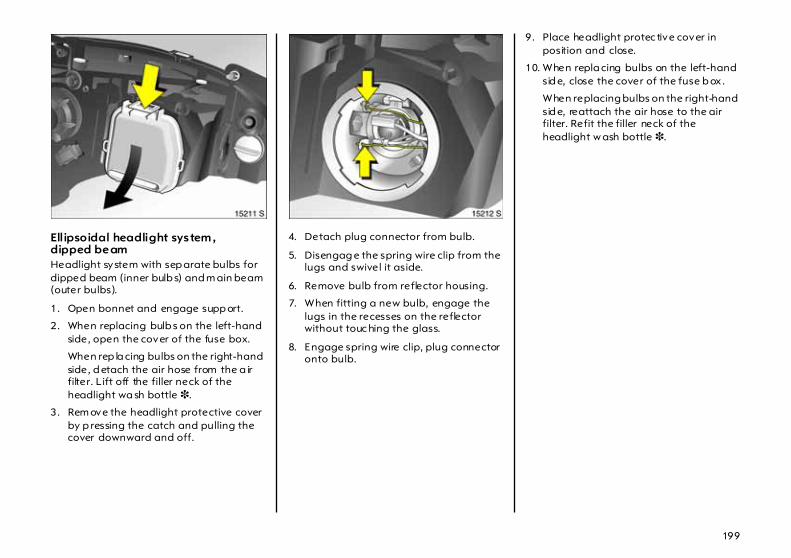
199
Ellipsoidal headlight system ,dipped beam Headlight system with sep arate bulbs for dipped beam (inner bulb s) and m ain beam (outer bulbs).
1. Open bonnet and engage supp ort.
2. When replacing bulb s on the left-hand side, open the cover of the fuse box.
When rep la cing bulbs on the right-hand side, d etach the air hose from the a ir filter. Lift off the filler neck of the headlight wa sh bottle 3.
3. Rem ove the headlight protective cover by p ressing the catch and pulling the cover downward and off.
4. Detach plug connector from bulb.
5. Disengag e the spring wire clip from the lugs and swivel it aside.
6. Remove bulb from reflector housing.
7. When fitting a new bulb, engage the lugs in the recesses on the reflector without touc hing the glass.
8. Engage spring wire clip, plug connector onto bulb.
9. Place headlight protec tive cover in position and close.
10. When repla cing bulbs on the left-hand sid e, close the cover of the fuse b ox.
When replacing bulbs on the right-hand sid e, reattach the air hose to the air filter. Refit the filler neck of the headlight w ash bottle 3.

200
Ellipsoidal headlight system ,front indicator lights 1. Open bonnet and engage supp ort.
2. When replacing bulb s on the left-hand side, open the cover of the fuse b ox. For engine Z 13 DT1), also pull the relay box (in front of the fuse b ox) up and out of the guides.
When rep la cing bulbs on the right-hand side, d etach the air hose from the a ir filter.
3. Rotate b ulb holder to left a nd disengage.
4. Push b ulb into holder a little, rota te left and remove.
5. Insert new bulb, without touching the gla ss.
6. Engage holder into reflector by rotating to the right.
7. When replacing bulbs on the left-hand side, c lose the cover of the fuse box. For engine Z 13 DT1), also position and engage the relay box.
When replacing bulb s on the right-hand side, rea ttac h the air hose to the air filter.
Ellipsoidal headlight system,main beam , parking lights We recommend that you have bulbs changed by your Va uxha ll Authorised Repairer.
1) Sa les designation – see page 228.

201
Xenon headlight system,dipped beam Headlight system with sep arate bulbs for dipped beam (inner bulb s) and m ain beam (outer bulbs).
Xenon headlight system,front indicator lights 1. Open bonnet and eng age support.
2. When replacing bulbs on the left-hand side, open the cover of the fuse box. For engine Z 13 DT1) , also pull the relay box (in front of the fuse box) up and out of the guides.
When replacing bulb s on the right-hand side, detach the air hose from the air filter.
3. Rotate bulb holder to left and disenga ge.
4. Push bulb into holder a little, rotate left and remove.
5. Insert new bulb, without touching the glass.
6. Engag e holder into reflector by rotating to the right.
7. When repla cing bulbs on the left-hand sid e, close the cover of the fuse box. For engine Z 13 DT1), also position and engag e the relay box.
When replacing bulbs on the right-hand sid e, reattach the air hose to the air filter.
The Xenon headlight dipp ed beam op erates at very hig h voltage. Do not touch the ignition system; danger to life. We recomm end that you ha ve the b ulbs cha nged by your Vauxhall Authorised Repairer.
1) Sales designation – s ee page 228.
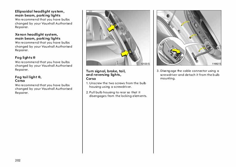
202
Ellipsoidal headlight system ,main beam, parking lights We recommend that you have bulbs changed by your Vauxhall Authorised Repairer.
Xenon headlight system,main beam, parking lights We recommend that you have bulbs changed by your Vauxhall Authorised Repairer.
Fog lights 3 We recommend that you have bulbs changed by your Vauxhall Authorised Repairer.
Fog tail l ight 3,CorsaWe recommend that you have bulbs changed by your Vauxhall Authorised Repairer.
Turn signal, brake, tail,and revers ing lights ,Corsa 1. Unscrew the two screws from the bulb
housing using a screwdriver.
2. Pull bulb housing to rear so that it disengages from the locking elem ents.
3. Diseng age the cable connector using a screwdriver and detach it from the b ulb mounting.

203
4. Unscrew the four sc rews from the b ulb mounting using a screwdriver. Detach the bulb mounting from the housing.
Lights from top to bottom:Ind icator lightBra ke lig ht/rear lightReversing light
5. Remove bulb from socket.
6. Insert new bulb (without touc hing the glass), fit bulb m ounting into housing and secure w ith screws. Engage cable connector, insert b ulb housing in vehicle body with fixing p ins and secure with screws.
Brake lights, rear lights, indicator lights , reversing lights andfog tail l ights,Combo 1. Disengage cover by pressing retaining
lugs and rem ove.
2. Detach plug connector from bulb mounting.
3. Grip the bulb housing from the outside, slacken the two knurled nuts using the wheel bolt key and unscrew b y hand.
4. Detach bulb housing.

204
5. Press reta ining lugs on bulb m ounting together and remove bulb mounting, as shown in illustration.
Lights from top to bottom:Reversing light/brake lightInd icator lightReversing lightFog tail light1)
6. Remove bulb from socket.
7. Insert new bulb, without touching the glass. Engage bulb mounting in bulb housing. Insert bulb housing into vehicle body. Screw fix ing nuts onto setsc rews by hand and tig hten. Enga ge p lug connector. Place cover in position and close.
Number plate light Corsa
1. Insert screwd river vertically on right-hand side of bulb housing , exert pressure towards the right and disengage spring. Remove the bulb housing downw ards.
2. Rotate bulb holder to left and disengage.
1) Co untry-specific versio n: Fog ta il light on left only.

205
3. Remove bulb from socket.
4. Insert new bulb, without touching the glass.
5. Rotate bulb m ounting clockwise and engage. Insert bulb housing and engage.
Comb o
1. Unscrew b oth screw s. Remove light insert.
2. Press b ulb slightly towards spring clip and rem ove.
3. Insert new b ulb, without touching the glass.
4. Insert light insert and secure using a screwdriver.

206
Courtesy light,rear reading lights 3,luggage compartment lights Close doors or hold down contact switch before removing lights so that they are not live.
1. Prise lig ht out of recess using a screwdriver.
2. Press bulb slig htly towards spring c lip and remove.
3. Insert new bulb, without touc hing the glass.
4. Insert light in opening a nd engage in position.
Front courtesy light and reading lights 3 Close doors before rem oving lights so that they are not live.
1. Lever lens out of housing.
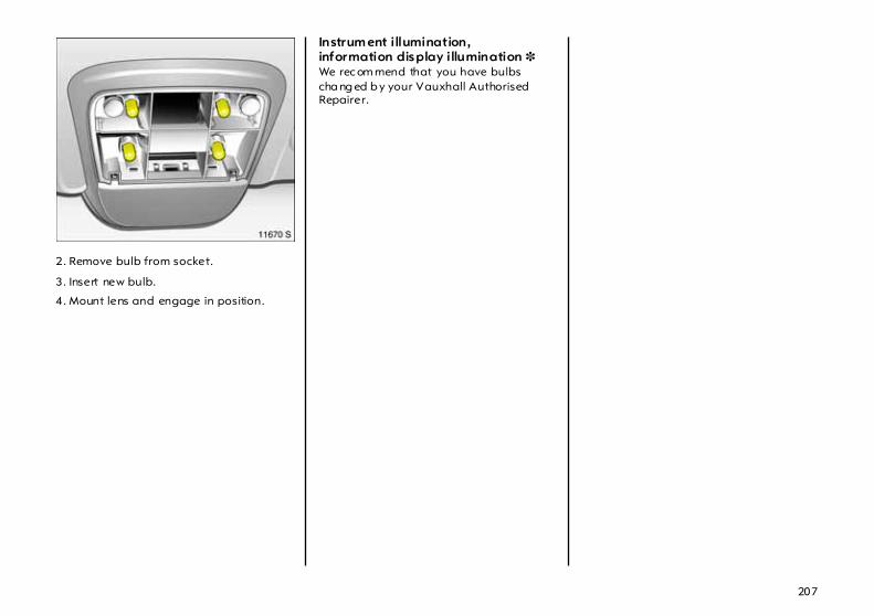
207
2. Remove bulb from socket.
3. Insert new bulb.
4. Mount lens and engage in position.
Instrum ent illumination,information display illumination 3 We rec om mend that you have bulbs cha ng ed b y your Vauxhall Authorised Repairer.

208
If you have a problem
In our experience the m ost comm on ca use of all comp la ints is the result of misundersta nding or la ck of communication between the customer and the Vauxhall Authorised Rep airer.
We sincerely hope you will never have cause to c om plain about your vehicle. However, if things do g o wrong, the b est course of action for you to take is to contact your Vauxhall Authorised Repairer’s Service Rec eption Staff and explain the d ifficulty you are having. We are confident they will do their utmost to resolve the problem to your comp lete satisfaction.
Sometimes, however, despite the b est of intentions of all c oncerned, misundersta ndings can occur. If your problem has not been resolved to your satisfaction, please make an app ointment to discuss the matter with the Manager of
the department c oncerned.
The majority of areas of concern can be quic kly resolved in this way.
Should you wish to pursue the matter further, the Principal of the Vauxhall Authorised Repairer should be made aware of your concern. It is ad visab le in cases such as this to write to him to confirm your problem and the solutions that have been offered.
You can be assured the Authorised Repairer’s Principal w ill only be too anxious to fully investigate your prob lems and correct any errors m ade. After a ll, he has a large investm ent in his business and is proud of his reputation and professionalism and fully realises that satisfied c ustomers are his key to success.
In the unlikely event that you are still not ha ppy with the answer your Vauxhall Authorised Repairer has given, or the action he prop oses to correct the problem, you may conta ct the Customer Care Department1) w here a team of Custom er Care Consultants will spare no effort to ensure your complete satisfa ction.
Va uxhall Motors Ltd.Customer Ca re,Griffin House,Osborne Road, LUTON, Beds., LU1 3YTTelep hone: 01582 427200
They w ill review all the facts involved. Then if it is felt some further action can be taken, the Vauxhall Authorised Repairer will b e adv ised accordingly. In any case, your contact will b e ac knowledged confirm ing Vauxhall Motors’ position in the m atter.
If you are not satisfied with the outcome, you ca n if you wish, seek advice from an independent third p arty suc h as:
Autom obile Association (A.A. )Fanum House, BASINGSTOKE,Hants., R G21 2EA
Royal Autom obile Club (R.A.C.),R.A.C. M otoring Services Ltd.,89-91 Pall Mall,LONDON, SW1Y S45
The Customer Relations Dep artment,Soc iety of Motor Manufactur ers and Trad ers Ltd. (S .M.M.T.),Forbes House, H alkin Street, LONDON, SW1X 7DS
Customer Complaints Service,Sc ottish Motor Tra de Association, (S.M.T.A.),3 Palmerston Place,EDINBURGH, EH 12 5AQ
The National Conciliation Serv ice,Retai l Motor Indust ry Federation,9 North Street, RUGBY, CV21 2AB
I f you have a problem w hilst ab road:The Service Departm ents of Adam Op el AG and General M otors branches everywhere will provid e information and assistance:
1) Calls may be mo nito red and recorded fo r tra in in g purposes.

209
Opel Austria Vertriebs GmbHGroß-Enzersdorfer S tr. 59 1220 Vienna – AustriaTel. 01-2 88 77 444 or 01-2 88 77 0
Opel Belgium N.V.Prins Boudewijnlaa n 30 2550 Kontich – Belgium Tel. 03-4 50 63 11
Opel C & S spol. s. r.o.Na Pank ráci 26 140 00 Pra gue 4 – Czech R epub lic Tel. 02-61 21-88 21
General Motors Da nm arkJaegersborg Alle 4 2920 Charlot tenlund – Denmark Tel. 39 97 85 00
Vauxhall Motors Ltd.Customer CareGriffin H ouse, Osborne Road Luton, Bedfordshire, LU1 3YT – Eng land Tel. 0 15 82-42 72 00
General Motors Finland OyPajuniityntie 5 00320 Helsinki – Finland Tel. Helsinki 61 58 81
General Motors France1 – 9, avenue du MaraisAngle Quai de Bezons 95101 Ar genteuil Cedex – Franc e Tel. 1-34 26 30 00
ADAM OPEL AGBahnhofsplatz 1 65423 Rüsselsheim – Germany Tel. 0 61 42-77 50 00 or 0 61 42-7 70
General Motors Hellas S.A.56 Kifisias Avenue & Delfon str.Am arousion 151 25 Athens – Greece Tel. 1-6 80 65 01
Opel Southeast Europe Ltd .Szabad sag utc a 117 2040 Buda örs – Hungary Tel. 06-23 446 100
General Motors IndiaSixth Floor, Tow er AGlob al Business ParkMehrauli – Gurgaon Road Gurgaon 122 022, Ha ryana – India Tel. 0124 280 3333
Opel Irela nd Ltd.Opel House, Unit 60, Heather Road Sandyford, Dublin 18 – I reland Tel. 01-216 10 00
Opel Italia S .p.A.Piaz zale dell’Industria 40 00144 Rome – Italy Tel. 06-5 46 51
For Luxemb ourg – contactOpel Service Department inKontich – Belgium
Opel Nederland B.V.Lage Mosten 49 – 63 4822 N K Breda – Netherlands Tel 0 76-5 44 88 00
General Motors Norge ASKjeller-Vest 6 2027 Kjeller – N or way Tel. 23 50 01 04
General Motors Poland Sp. z o. o.Domaniewska 41 06- 672 Wa rsa w – Pola nd Tel. 0 22-606 17 00
General Motors PortugalQuinta da FonteEdific ío Fernão Magalhães, Piso 2 2780-190 Paço d’Arcos – Portugal Tel. 21 440 75 00
Opel España de Autom óv iles S.A.Paseo de la Castellana, 91 28046 Madrid – Sp ain Tel. 902 25 00 25
Saab Opel Sverig e ABEsboga ta n 8 164 74 Kista – Sw eden Tel. 08-632 85 00
General Motors Suisse S.A.Salzhausstra ße 21 2501 Biel/Bienne – S witzerland Tel. 0848 810 820 or 0 32-3 21 51 11
Opel Türkiye Ltd. S ti.Kemalp asa yolu üzeri 35861 Torb ali / Izmi r – Turkey Tel. 02 32-8 53-14 53
In Albania, Bosnia -Her zegovina ,Bulga ria, Croatia , Macedonia ,Rom ania, S lovenia and Yugosla via please contact the OpelService Depa rtm ent in Budaörs – HungaryTel. 00 36-23 446 100

210
Maintenance,inspection System
In ord er to guarantee economical and sa fe vehic le operation a nd to maintain the value of your vehicle, it is of vital importance tha t all maintenance work is carried out at the p roper intervals as specified by Vauxhall.
The oil c hange and serv ice intervals are flex ible, based on a numb er of different param eters and the conditions under which the vehicle is used. Various engine-specific da ta is c ontinuously record ed a nd used to ca lc ulate the remaining distance until the next service is due.
This rem aining distance can be shown on the speedometer display w ith the ignition off and the mileage odometer off: Press the actuating knob und er the odometer, InsP and the remaining dista nce will b e displayed.
If the remaining dista nce is less than 1000 miles (1500 km), InsP is displayed w ith a remaining distanc e of 600 miles (1000 km) when the ig nition is sw itched on. InsP is displayed for several second s if the remaining distance is less than 300 miles (500 km ). Have the serv ice work that is due carried out within one week or 300 miles (500 km). H ave this work c arried out by a Vauxhall Authorised Repairer in order to avoid loss of wa rranty claims.
The service interval display takes acc ount of off-the-road periods during which the battery is disconnected.
Further information on maintenance and the inspection system can be found in the service booklet, which is in the glove compa rtm ent.
Have maintena nce work, as well as repairs to the b odywork and units, ca rried out by a professional. We recommend your Vauxhall Authorised Repairer, who is familiar w ith Vauxhall vehicles and in possession of the necessary special tools and the latest service instructions from Vauxhall. In order to avoid inva lid ation of any warranty claim, it is espec ially important to entrust work to a Vauxhall Authorised Repa irer during the wa rra nty period . For further information, see the Service Booklet.
Sepa rate anti-c orrosion service Have this service performed once a year, either as part of an Annual Insp ection or sepa ra tely; see Servic e Booklet. To avoid invalidation of any warranty claim aga inst rust-through, we recomm end that you consult your Vauxhall Authorised Repa irer.

211
A note on safety Always switch ignition off when performing checks in the engine compartment (e.g. check ing the b ra ke fluid level or the eng ine oil level) due to risk of injury from live cables and rotating parts.
Never ca rry out any repairs or a djustment and maintenance work on the vehicle yourself. This especially applies to the engine, cha ssis a nd safety parts. You m ay unwittingly infringe the provisions of the law and, by not performing the work prop erly, endanger yourself and other road users.
Checking and topping up fluids The ca ps for topping up the engine oil, the coolant, the washing fluid and the oil dipstick handle are yellow for ease of identification.
The cooling fan is controlled by a thermo-switch a nd can therefore start unexpectedly even if the ignition is switched off. Risk of injury.
Elec tronic ig nition system s genera te very high voltag es. Do not touch the ignition system ; high voltage can be fatal.

212
Engine oil Information on engine oils is available in the Service Booklet.
Eng ine oi l level and consum ption All engines c onsume oil for technica l rea sons. The engine oil consump tion ca n only be assessed after d riv ing a long distance, and may be above the specified value during the initial stage (run-in period). Frequent driving a t hig h revs causes oil consumption to increa se.
Therefore, chec k the engine oil level, particularly before undertak ing a long journey.
Engine oil level chec k,topping up engine oilThe illustrations show chec king and top ping up of various petrol and diesel engines.
The oil level m ust be checked with the vehicle horizontal and with the engine (w hich m ust be at operating temp erature) switched off. Wait at least five minutes before checking the level to allow the normal oil accumulation in the engine to drain back into the oil pan.
To chec k the oil level, wipe oil d ip stick and insert up to stop on handle. Top up if the oil level is near the MIN m ark.
The oil level must not go above the upper ma rk MAX on the dipstick. Excess oil must be dra ined or extracted by suction. If the oil level does go above the mark MAX there is a risk of damage to the engine or ca ta lytic converter.
The amount filled must be between the MIN and MA X marks – see pag e 248.
Im porta nt : I t is the owner’s responsibility to maintain the proper level of an appropriate quality oil in the engine.

213
When topping up, use the same type of oil as used during the la st oil chang e and pay strict attention to the instructions in the Service Booklet.
Ca pacities – see p age 248.
Oil c hange, oil fil ter change Change the oil at the disp la yed service intervals.
We rec om mend that you use genuine Vauxhall oil filters.
Used oil filters and empty oil containers should not be disp osed of as domestic refuse. We recomm end that you entrust oil and oil filter changes to a Va uxha ll Authorised Repa irer, who is familiar with legal requirem ents reg arding disposa l of used oil and can thus help to p rotect both the env ironment and your hea lth.
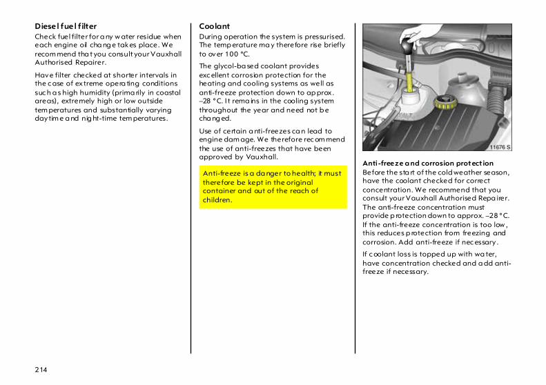
214
Diesel fuel f ilter Check fuel filter for a ny w ater residue when each engine oil cha ng e takes place. We recom mend tha t you consult your Vauxhall Authorised Repairer.
Have filter checked at shorter intervals in the c ase of extreme opera ting conditions suc h a s high humidity (prima rily in coastal areas), extremely high or low outside tem peratures and substantially varying daytim e a nd nig ht-time tem peratures.
Coolant During operation the system is pressurised. The temp erature ma y therefore rise briefly to over 100 °C.
The glycol-ba sed coolant provides exc ellent corrosion protection for the heating and cooling systems as well as anti-freeze protection down to ap prox . –28 °C. I t rema ins in the cooling system throughout the year and need not b e cha ng ed.
Use of certain a nti-freezes ca n lead to engine dam age. We therefore rec om mend the use of anti-freezes that have been approved by Vauxhall.
Anti -freeze a nd corrosion protect ionBefore the sta rt of the cold weather season, have the coolant checked for correct concentration. We recommend that you consult your Vauxhall Authorised Repa irer. The anti-freeze concentration must provide p rotection down to approx. –28 °C. If the anti-freeze concentration is too low , this reduces p rotection from freezing and corrosion. Add anti-freeze if nec essary .
If c oolant loss is topped up with wa ter, have concentration checked and a dd anti-freeze if necessary.
Anti-freeze is a da nger to health; it must therefore be kept in the original container and out of the reach of children.

215
Coola nt level Hardly any losses occur since the cooling system is sealed and it is thus rarely necessary to top up the c oolant.
The c oolant in the compensation tank should b e slightly above the mark KALT/COLD with the cooling system cold. It rises when the engine is wa rm and falls again as it c ools. If it drop s b elow the marking in this case, it should be topped up to a level just above the marking.
Top up anti-freeze. I f no anti-freeze is available, top up w ith c lean tap water. If tap water is unavailable, distilled water can be used.
After topping up w ith tap or distilled water, ha ve the anti-freez e concentration checked, a nd anti-freeze added if necessary. H ave the cause of the coolant loss remedied. We recommend that you consult your Vauxhall Authorised Rep airer.
When closing, tighten coola nt filler cap as fa r as it will go.
Coolant temp era ture For physical reasons, the engine temperature gauge shows the coolant temperature only if the coolant level is adequate.
During operation the system is pressurised. The tem perature may therefore rise to over 100 °C.
If the temp erature g auge enters the red zone, check the coolant level immediately. z Low coolant level:
Top up coolant. Pay attention to the instructions given under "Anti-freeze and corrosion protection" and "Coolant level". Have the cause of coolant loss remedied . We recommend that you consult your Vauxhall Authorised Repairer.
z Coolant level OK:Have the c ause of inc reased coolant temperature remed ied. Contact a workshop. We rec om mend that you consult your Vauxhall Authorised Repairer.
Allow engine to cool d ow n before removing coola nt filler ca p. Remove filler cap carefully so that p ressure can escape slowly, otherwise there is a risk of scalding.

216
Brake fluid Brake fluid is hygroscopic, i. e. it ab sorbs water. If the brakes b ecome hot, suc h as when d riv ing on long downhill stretches, vap our bubb les can occur in the w ater, which can have an extrem ely adverse effect on braking power (depending on the proportion of w ater).
The fluid change intervals specified in the Service Booklet m ust therefore be observed.
Windscreen wiper Clea r vision is essential for safe driv ing.
The cleaning effect of the windscreen wiper and the windscreen washing system 3 should therefore be checked at regular intervals. We recommend repla cing the wiper b la des at least once a yea r.
If the windscreen is dirty, operate the screen wash before switching on the wind screen wiper or setting the w iper to autom atic opera tion w ith the rain sensor 3 . This will avoid wiper blade wear.
Do not switch on the wind screen wiper or set them to automa tic operation with the ra in sensor 3 if the windscreen is iced up as this could dama ge the wiper b la des or the wiper system .
If the wiper bec om es frozen on to the glass, we rec om mend that they be released with the aid of Vauxhall De-icer Spray .
Smearing wiper blades c an be cleaned with a soft c loth and Vauxhall Clea ning Solvent and Anti-Freez e.
Wiper blades whose lips have become hardened, cracked or covered with silicone must be replac ed. This may be necessary as a result of the effects of ic e, thawing salt or hea t, or the incorrect use of cleaning agents.
Switc h off w indscreen wiper or autom atic wiper system w ith rain sensor 3 in ca r washes – see pages 17, 222.
Windscreen wiper blade maintenance – see pag e 224.
We recom mend that you ha ve brake fluid changed by a Va uxha ll Authorised Repairer, who will be familiar with the requirements of the law as regards disposal of brake fluid and can thus help to protect the environment and your health.
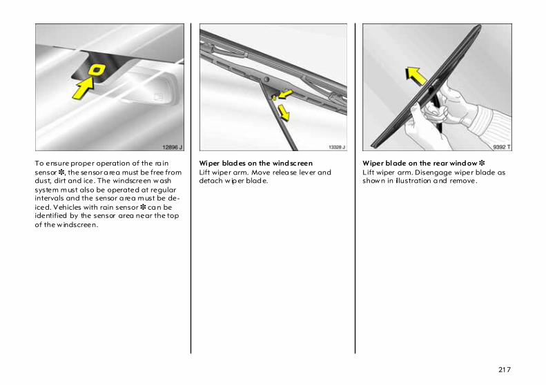
217
To ensure proper operation of the ra in sensor 3, the sensor a rea must be free from dust, dirt and ice. The windscreen w ash system m ust also be operated at regular intervals and the sensor a rea m ust be de-iced. Vehicles with rain sensor 3 ca n be identified by the sensor area near the top of the w indscreen.
Wiper blad es on the wind sc reen Lift wiper arm. Move relea se lever and detach w ip er blad e.
Wiper blade on the rear wind ow 3 Lift wiper arm. Disengage wiper blade as show n in illustration a nd remove.

218
Windscreen and headlight wash systems 3 Reservoir for wind screen wash and rear windscreen wash at driver’s side in engine compartment.
In vehicles with head lig ht washing system 3, the filler opening is in the engine compartment behind the right-hand head lig ht – see Fig. 14246 S.
Fill only with clean w ater to prevent the nozzles from clogging. To improve cleaning efficiency, we recommend that you add a little Vauxhall Wind screen Wash Solvent.
The windscreen wash system and headlight wash system w ill not freeze in winter:
When closing the container, press the lid firmly over the beaded ed ge a ll the way round.
Battery The battery is m aintenance-free.
Retrofitted electrical or electronic acc essories can p lace an additional load on the battery or even discha rg e the battery. We recom mend that you consult a Vauxhall Authorised Repairer regarding technical possibilities, suc h as fitting a more powerful battery.
Frost protection down to
M ixture – Vauxhall Windscreen Wash
Solvent: Water
– 5 °C 1 : 3
– 10 °C 1 : 2
– 20 °C 1 : 1
– 30 °C 2 : 1
We recom mend ha ving the ba ttery chang e ca rried out by a Vauxhall Authorised Repa irer, who will be fam ilia r with the requirements of the law as regards disposa l of old batteries and can thus help to p rotect the env ironment and your health.

219
Parking the vehicle for more than 4 weeks can lead to ba ttery discharging. This may red uce the service life of the b attery. Disconnect battery from on-board power sup ply by disconnecting the neg ative term inal (Vauxhall alarm system 3 is then disabled ).
Ensure that ignition is switched off before connecting battery. Then perform the follow ing actions:
z Set da te and time in information d isplay – see page 38.
z If necessary, activate window elec tronics 3. See pag e 104.
z Calibrate steering angle sensor (ESP) 3 – see pa ge 149.
In order to prevent the b attery from discharging , som e c onsumers suc h as the courtesy light automatically switch off after approx. 30 minutes.
Protecting electronic com ponents In order to prevent faults in electronic components in the electrica l system, never connect or disconnect battery with engine running or ignition switched on. Never start engine w ith b attery disconnected, e.g. when starting using jump leads.
To avoid damaging the vehic le, d o not ma ke a ny modifications to the electrical system, e. g. c onnec ting additional consum ers or tampering with electronic control units (chip tuning).
Disconnect/connec t vehicle ba ttery fr om/to electrical systemDisconnect the b attery from the vehic le electrical system before charging : First detach the negative and then the positive lead. Do not reverse the polarity of the battery, i.e. do not confuse the terminals for the p ositive and neg ative leads. When connecting, sta rt with the positive lead and then c onnec t the neg ative lead.
Electronic ignition system s generate very hig h voltages. Do not touch the ignition system; high voltage can b e fatal.
220
Vehicle decom missioning Observe na tional regulations.
If the vehicle is decomm issioned for several months, the follow ing work must be ca rried out in order to prevent damage. We recom mend tha t you consult your Vauxhall Authorised Repairer.
z Wash and preserve the vehicle – see page 222.
z Check protective coating in engine com partment a nd on underbody a nd rectify where necessary .
z Clean and preserve rubber seals on bonnet and doors.
z Change engine oil – see page 213.
z Check anti-freeze and c orrosion protection – see page 214.
z Check the coola nt level, top up with anti-freeze if nec essary – see pag e 215.
z Empty windsc reen w ash system and headlight wash system.
z Inc rease ty re pressure to value sp ecified for m aximum load – see page 243.
Vehicle storag e z Park vehicle in dry and well-ventilated
premises. With manua l transmission, eng age first gear or reverse gear. With Easytronic 3 , place selector lever in mid position b efore switching off ignition. With autom atic transmission 3, place selector lever in P. Place wheel choc ks or suc hlike under wheels to prevent vehic le from rolling away.
z Do not apply hand brake.
z Disconnect battery by disengaging neg ative terminal from vehicle electrical system – see page 218.
Vehicle recomm issioningObserve national regulations.
Perform the following work before recommissioning the vehicle:
z Connect ba ttery – see page 218.
z Check tyre pressure and correc t if necessary. See pag e 243.
z Fill up w indscreen wash system – see page 218.
z Check engine oil level – see p age 212.
z Check the coolant level ; top up with anti-freez e if necessa ry – see pa ge 215.
z Fit the num ber p la te if necessary .
221
Vehicle care Obtain adv ice from a Vauxhall Authorised Repairer regarding cleaning materials tha t ha ve b een tested a nd recomm ended by Vauxhall.
When caring for your vehicle, observe all na tional environm ental reg ulations, particula rly when wa shing it.
Regular, thorough care helps to improve the appearance of your vehicle and maintain its value over the years. It is a lso a prerequisite for warranty claims for any paint or corrosion damag e. The following pages contain tips for vehicle care which, if used properly , will help combat the unavoida ble d amaging effects of the environment.
Vehicle care aids 3 Vehicle wash: z Wa sh brush z Shampoo z Sponge z Insect Removal Sponge z Chamois
Vehicle care: z Paintwork Clea ner z Paintwork Polish z Metallic Paintwork Wax z Hard wa x z Vauxhall Touch-Up Paint z Vauxhall Touch-Up / Aerosol Paint z Wheel Preserver z Tar Rem over z Insect Remover z Window Cleaner,z Vauxhall Windscreen Wa sh Solvent z Silicone Oil for Rubber Sea ls z Cleaner

222
Washing The paintwork of your vehicle is exposed to env ironmenta l influences, e.g. continuous changes in weather conditions, ind ustrial waste gases and dust or tha wing sa lts, so wash and wax your vehicle regularly. When using a utoma tic car washes, select a programme which includes wax ing.
Bird droppings, dead insects, resin, pollen and the like should be cleaned off immediately , as they contain aggressive constituents which can cause paint dam age.
When using c ar washes, follow the relevant instructions of the car wash facility. The windscreen wiper or a utomatic wiper system w ith rain sensor 3 and the rea r window wiper 3 m ust be switched off – see page 18. Remove the aerial 3 and the roof rack 3.
If you w ash your vehicle by hand, make sure that the insides of the wing s a re also thoroughly rinsed out.
Clea n edges and folds on op ened doors and flaps as well a s the area s they cover.
Thoroughly rinse off and leather-off the vehicle. Rinse leather frequently . Use separate leathers for paint and w indow surfaces: remnants of wax on the wind ow s will impair vision.
Observe national regulations.
Waxing Wax your vehicle regularly, in pa rticular after it has been washed using shampoo and at the latest when wa ter no longer forms beads on the pa intwork, otherwise the paintwork will d ry out.
Also wax edg es a nd folds on op ened doors and flaps as well a s the area s they cover.
Polishing Polishing is necessary only if the pa int has become dull or if solid deposits have become attached to it.
Paintwork polish with silicone forms a protec tive film, making w axing unnecessary.
Plastic body parts should not be treated with wax and polish.
Use Metallic Paintwork Wax on vehicles with a metallic-effect paint finish.
Wheels Use a pH-neutral w heel c leaning agent to clean the wheels.
Wheels a re painted and ca n be treated with the same ag ents as the body. For alloy wheels we recomm end use of Alloy Wheel Preserver.

223
Paintwork damage Repair small area s of p aint damage suc h as stone impacts, scratches etc. immediately using a n Vauxhall touch-up applicator or Vauxhall sp ra y and touch-up paint before rust can form . If rust has alrea dy formed, ha ve the c ause remedied. We recommend that you consult your Vauxhall Authorised Repairer. Please also pay attention to surfaces and edg es beneath the vehicle where which rust ma y have form ed unnoticed for some time.
Tar spots Tar spots must not be rem oved with ha rd objects, b ut instead immediately cleaned off with Tar Removal Spray. Do not use tar rem oval spray on headlight and other exterior light bezels.
Exterior lights Headlight and other protective lig ht bezels are made of plastic. If they require additional cleaning after the vehicle has been washed, clea n them with Car Shamp oo. Do not use any ab ra sive or caustic agents, do not use an ice scraper, and do not clean them dry.
Plastic and rubber parts If the carw ash does not c lean plastic and rubb er parts adequately , use cleaner suitable for vehicle interiors. Do not use a ny other agent, and in particular do not use solvents or petrol.
Do not use high-pressure jet clea ners on wheels and tyres.
Wheels and tyres Do not use high-pressure jet clea ners on wheels and tyres.
Interior and upholstery Clean the vehicle interior, including the instrument panel fascia, using interior cleaner.
C lean fabric upholstery w ith a vacuum cleaner and brush. To remove stains, use cleaner tha t is suitable for both fabrics and vinyl.
Do not use cleaning agents suc h as acetone, c arbon tetrachlorid e, paint thinner, paint remover, nail varnish remover, washing pow der or b leach to clean fabrics, carpets, the dashboard or leather trim 3 in the vehicle interior. Benzine is also unsuita ble.
Seat belts Always keep seat b elts clean a nd dry.
C lean only with lukewarm w ater or Cleaner.

224
Windows When cleaning the heated rea r window 3, make sure tha t the heating element on the inside of the wind ow is not d amaged.
Use a soft lint-free cloth or chamois leather in conjunction with Wind ow Cleaner and Insect Remover.
Vauxhall C leaning Solvent and Anti-Freeze is suitable for de-icing wind ow s.
For mechanical removal of ice, use a commercially a vailable sharp-edged ice scraper. Press the sc ra per firmly against the g lass so that no dirt can get und er it and scratch the glass.
Windscreen wiper blades Wax such as the wax used in car w ashes can cause smearing on the windscreen when the w indscreen wiper is switched on.
Smearing wiper blades can be c leaned with a soft cloth a nd Vauxhall Cleaning Solvent and Anti-Freeze, and replaced if necessary – see page 216.
Locks The locks are lubricated with a hig h-grad e lock cylinder grease at the fac tory . Vauxhall lock cylinder grease prevents the locks from freezing up. Only use de-ic ing agent in emerg encies, a s they have a degreasing effect a nd will impair the function of the locks. After using a de-icing agent, have the locks re-greased. We recommend that you entrust this to your Vauxhall Authorised Repairer.
Engine compartment Clean painted surfaces in the engine compa rtm ent like any other painted surfac e. For best results, wash and w ax the eng ine compartm ent before and after winter. Before washing the engine, cover the alternator and brake fluid reservoir with plastic sheeting.
When washing the engine with a steam -jet cleaner, d o not direct the steam jet at components of the Anti-lock Brake System 3 , the a utoma tic air conditioning system 3 or the belt drive and its components.
Protective wax that has been applied is also rem oved during the engine wash. For this reason, have the engine, brake system components in the engine c om partment, ax le components with steering , body parts and c avities thoroughly preserved with protec tive w ax after the wash. We recommend that you consult your Vauxhall Authorised Repa irer.
An eng ine wash can be performed in the spring in order to remove dirt that has adhered to the engine compartment, which ma y also have a high salt content. Check protective wax layer and make good if nec essary .
Do not use high-pressure jet c leaners on wheels and tyres.

225
Underbody Your vehicle has a fa ctory-applied PVC undercoating in the wheel arches (includ ing the longitudinal members) w hich provides permanent protection and needs no special m aintenance. The surfaces of the vehicle underbody not covered b y PVC are provided with a durable protective w ax coating in critical areas.
On vehicles which are washed frequently in automatic car washes with underbody washing facility , the protective wax coating may be imp aired by dirt-dissolving additives, so check the underbody after washing and have it waxed if necessary. Before the start of the cold weather season, check the PVC coating and protective wax coating and, if necessary, have them restored to perfec t cond ition.
Ca ution – com mercially available bitumen/rubber materials can d amage the PVC coating. We recomm end that you have underbody work carried out by a Vauxhall Authorised Repairer, who knows the prescribed materials a nd has experience in the use thereof.
The underbody should be washed follow ing the end of the cold w eather season to remove any dirt adhering to the underbody, since this may also c ontain salt. Check protective wax coating a nd , if necessary, have it restored to p erfect condition.
Folding roof 3 The operation, ap pearance and service life of the folding roof mainly depend on correct opera tion and cleaning.
Brush clea n in front to rear direction using soft brush (dry).
Rinse with clean w ater.
In case of heavy soiling: brush roof in one direction with car shampoo and lukewarm water. Rinse with clean w ater.
Alw ays wash the entire roof.
Allow wet roof to dry - keep c losed .
z Do not use high-pressure jet c leaners on wheels a nd tyres.
z Remove bird droppings im med ia tely.
z Do not use aggressive cleaning agents or stain removers.
z With roof open, clean slide rails a nd sliding p arts and grease with acid-free grease once per annum . C lean rubber parts as described in "Plastic and Rubber Parts" – page 223.
z Check wind deflector water drains for blockages and clean if necessary.
z Do not remove snow and ice using sharp objects.

226
Technical Data
Vehicle docum ents, identification plate The tec hnical d ata is determined in accor-dance w ith European Community stan-dards. We reserve the right to ma ke m odi-fica tions. Sp ecifications in the vehicle doc-um ents always have priority over those giv-en in this manual.
The identification plate is affixed to the front right door frame.
In other versions the type plate is attached to the right spring strut dome in the engine compa rtm ent.

227
Information on id entific ation p la te:
1 Manufacturer 2 Type approval number 3 Vehicle identification number 4 Permissible gross vehicle w eight 5 Permissible gross train weight 6 Maximum permissible front axle load 7 Maximum permissible rear axle load 8 Vehicle-sp ecific or
country-specific d ata
Vehicle identification data The vehic le identification number is stamp ed on the id entific ation pla te and in the vehicle floor on the right-hand sid e un-der a cover between the front pa ssenger door and seat.
In other design variants, the identification plate m ay also be affixed to the d ash-board.
Engine c od e and engine number. Ma rked on engine b lock at left side of engine in petrol engines, and beneath diesel injec-tion pump at right side of engine in diesel engines.
Coolant, brake fluid, oils When topping up – coola nt,– brake fluid, – manual transmission oil,– autom atic transmission oil we rec om mend that you consult your Vauxhall Authorised Rep airer, who can ad-vise you on the correct products to use.
Caution: Use of unsuitable fluids can cause serious damage to the vehicle.
Engine oils Information on engine oils is availab le in the Serv ice Booklet.

228
Engine data
Sales designationEng ine identifier code
1.0 TWINPORTZ 10 XEP
1.2 TWINPORTZ 12 XEP
1.4Z 14 XE
1.4 TWINPOR TZ 14 XEP
1.8 Z 18 XE
Numb er of cylinders 3 4 4 4 4
Bore dia. (mm ) 73.4 73.4 77.6 73.4 80.5
Stroke (mm) 78.6 72.6 73.4 80,6 88.2
Piston displacement (cm 3) 998 1229 1389 1364 1796
Max. engine outp ut (kW)at rpm
445600
595600
666000
665600
926000
Torque (Nm ) at rpm
883800
1104000
1254000
1254000
1654600
Com pression ratio 10.5 10.5 10.5 10.5 10.5
Octane requirement (RON)1)
unleadedor unleadedor unleaded
1) Stan dard high-quality fuels , e.g . unleaded DIN EN 228; value printed in bold: reco mmended fuel.
95 (P)2)
98 (PP)2)
91 (R)2)3)
2) Kn ock contro l s ys tem automatically adjus ts ignition tim ing according to type o f fuel used (octane nu mber). 3) Slight reduction in engine ou tput and to rque if 91 RON is used.
95 (P)2)
98 (PP)2)
91 (R)2)3)
95 (P)2)
98 (PP)2)
91 (R)2)3)
95 (P)2)
98 (PP)2)
91 (R)2)3)
95 (P)2)
98 (PP)2)
91 (R)2)3)
–
Max. permissible engine speed,continuous operation (rpm) approx. 6200 6200 6500 6200 6500
Oil consumption (l/1000 km) 0.6 0.6 0.6 0.6 0.6

229
Engine data
Sales designationEng ine identifier code
1.3 CDTIZ 13 DT
1.7 DTY 17 DTL
1.7 CDTIZ 17 DTH
Numb er of cylinders 4 4 4
Bore dia. (mm ) 69,6 79.0 79.0
Stroke (mm) 82.0 86.0 86.0
Piston displacement (cm 3) 1248 1686 1686
Max. engine outp ut (kW)at rpm
514000
484400
744400
Torque (Nm ) at rpm
1701750 to 2500
1302000 to 3000
2402300
Com pression ratio 18.0 18.4 18.4
Cetane requirement (CN)1)
1) Stan dard qu ality fuels, e.g . Diesel D IN EN 590; D = Diesel; va lu e in bold = reco mmen ded fuel.
49 (D)2)
2) A lo wer value is pos sib le with w inter diesel fu els.
49 (D)2) 49 (D)2)
Max. permissible engine speed,continuous operation (rpm) approx. 5100 to 5300 5100 to 5300 5050 to 5150
Oil consumption (l/1000 km) 0.6 0.6 0.6

230
Perform ance (ap prox . mp h;km/h1)), Corsa
1) The maxim um s peed is ach ievable with a m aximum of h alf payload. Optional equipm ent m ay reduce th e specified m aximum speed of the vehicle.
Eng ine2)
2) Sa les designation – see pages 228, 229.
Z 10 XEP ECO3)
3) Usage-optimised equipm ent version, in conjunction with En gine Z 10 XEP.
Z 10 XEP Z 12 XEP Z 14 XE
Maximum speed5-speed ma nual transmissionSports transmissionEasytronicAutomatic transmission
––98;159–
–97;15697;156–
–108;175108;175–
–––106;170
Eng ine2)Z 14 XEP Z 18 XE Z 13 DT Z 17 DTH
Maximum speed5-speed ma nual transmissionSports transmissionEasytronicAutomatic transmission
–111;179110;177–
–126;202––
165–103;165–
188–––
Driving values (approx. km/h1)), Com bo
Eng ine2) Z 14 XEP Z 13 DT Y 17 DTL Z 17 DTH
Maximum speed5-speed ma nual transmission 102;164 92;150 91;147 106;170

231
Fuel consumption,CO2 emiss ions Directive 80/1268/EEC (last c hanged by 1999/100/EC) has applied for the measure-ment of fuel consumption sinc e 1996.
The direc tive is oriented to actual driving practices: Urban driv ing is rated at approx. 1/3 and off-road driving with ap prox . 2/3 (urban a nd extra-urban c onsumption). Cold starts and acceleration phases are also taken into consideration.
The specification of CO2 emission is also a constituent of the directive.
The figures given m ust not be taken as a guarantee for the actual fuel consumption of a p artic ular vehicle.
The calculation of fuel consumption as spec ified by directive 1999/100/EC takes acc ount of the vehicle’s kerb weight, ascer-tained in accordance with the said regula -tion. Optional extras ma y result in slig htly higher fuel consump tion and CO2 emission levels than those quoted.
To convert 1/100km into m pg, div id e 282 by num ber of litres/100km.
Save fuel, protec t the env ironment – see page 140.

232
Fuel consumption, CO2 emission Corsa
Eng ine1)
1) Sa les designation – see pages 228, 229.
Z 10 XEPECO 2)
2) Usage-optimised equipm ent version, in conjunction with En gine Z 10 XEP.
Z 10 XEP Z 12 XEP Z 14 XE
Manual/Sports/Easytronic/Automatic transm ission
Fuel consumption (approx. l/100 km )UrbanExtra-urb anCom bined
CO2 emission (app rox . g/km)UrbanExtra-urb anCom bined
–/–/ 6,3/––/–/ 3,9/––/–/ 4,8/–
–/–/151/––/–/ 94/––/–/115/–
–/ 6,9/ 6,7/––/ 4,4/ 4,3/––/ 5,3/ 5,2/–
– /166/161/–– /106/103/–– /127/125/–
– / 7,8/ 6,8/–– / 4,6/ 4,4/–– / 5,8/ 5,3/–
– /187/163/–– /110/106/–– /139/127/–
–/–/– /10,4–/–/– / 5,8–/–/– / 7,5
–/–/– / 250–/–/– / 139–/–/– / 180
Eng ine1) Z 14 XEP Z 18 XE Z 13 DT Z 17 DTH
Manual/Sports/Easytronic/Automatic transm ission
Fuel consumption (approx. l/100 km )UrbanExtra-urb anCom bined
CO2 emission (app rox . g/km)UrbanExtra-urb anCom bined
–/ 7,9/ 7,7/––/ 4,7/ 4,5/––/ 5,9/ 5,7/–
–/190/185/––/113/108/––/142/137/–
–/10,8/–/––/ 5,6/–/––/ 7,5/–/–
–/ 259/–/––/ 134/–/––/ 179/–/–
5,7/–/ 5,5/–3,8/– / 3,7/–4,5/– / 4,4/–
154/–/149/–103/–/100/–122/–/119/–
6,3/–/–/–3,8/–/–/–4,7/–/–/–
170/– /–/–108/– /–/–127/– /–/–

233
Fuel consumption, CO2 Emission Combo Eng ine1)
1) Sa les designation – see pages 228, 229.
Z 14 XEP Z 13 DT Y 17 DTL Z 17 DTH
Manual transm ission Fuel consumption (approx. l/100 km )
UrbanExtra-urb anCom bined
CO2 emission (app rox . g/km)UrbanExtra-urb anCom bined
8,05,36,3
192127151
6,54,35,1
176116138
6,64,75,4
178127146
2)
2) No valu es were available w hen this do cum ent went to press.

234
Weights, payload and roof load The p ayload is the difference between the permitted g ross vehicle weight (see identi-fication plate, page 226) and the EC kerb weight.
To calculate the kerb weight, enter the data for your vehicle below: z Kerb weight from
Ta ble 1,pages 235 to 241 + ... ..... .... .. kg
z Weight of heavyaccessories from Table 2,page 242 + ... ..... .... .. kg
The total = ... ..... .... .. kg
is the EC kerb w eight.
Optional equipment and accessories in-crea se the kerb w eight, which means tha t the p ayload will also change slig htly.
Note the weights given in the vehicle docu-ments.
The combined total of front a nd rear ax le loa ds must not exceed the perm issible gross vehicle weight. For exa mple, if the front axle is b earing its m aximum p ermissi-ble load, the rear ax le can only bear a load that is equal to the gross vehicle weight mi-nus the front axle load.
Corsa saloonWhen the caravan/trailer is coupled and the towing vehic le fully loaded (including all occupants), the perm issible rear ax le loa d (see identification plate or vehicle docum ents) may be exceeded by 45 kg and the permissible gross vehicle weight by 15 kg. If the permissib le rear axle load is exc eeded, a maximum speed of 60 mph (100 km/h) a pplies. If national regula tions specify a low er ma ximum speed for vehi-cles towing a ca ra van/trailer, this m ust be ob served.
See the identification p la te or vehicle docu-ments for permissible ax le load s.
Corsa deliver y va n, Com boThe permissible axle loads must not be ex-ceeded.
See the identification p la te or vehicle docu-ments for permissible ax le load s.
General inform ationThe permissib le roof load is 100 kg . The roof load consists of the weight of the roof rack plus the load carried.
Driving hints – see page 138.

235
Weights (kg), Table 1 , Kerb w eight1), Corsa Saloon
1) According to EC D irective 70/ 156/EC, including assum ed w eights fo r driver (68 kg), luggage (7 kg) and all fluids (tank 90 % full).
Model Eng ine2)
2) Sa les designation – see pages 228, 229.
3-d oor Manua l tra nsmission
Ea sytronic Automatic transmission
5-d oor Manua l tra nsmission
Easytronic Automatic transmission
Corsa Life ECO Z 10 XEP – 1030 – – 1055 –
Corsa Life ECO wi th air cond i-tioning system
Z 10 XEP – 1055 – – 1080 –
Corsa Life, Corsa Expression
Z 10 XEP 980 980 – 1005 1005 –
Z 12 XEP 1010 1010 – 1035 1035 –
Z 14 XE – – 1075 – – 1100
Z 14 XEP 1035 1035 – 1053 1053 –
Z 13 DT 1110 – – 1135 – –
Z 17 DTH 1155 – – 1163 – –
Corsa Life, Corsa Expression with air conditioningor climate control system
Z 10 XEP 1015 1015 – 1040 1040 –
Z 12 XEP 1035 1035 – 1060 1060 –
Z 14 XE – – 1100 – – 1125
Z 14 XEP 1060 1060 – 1078 1078
Z 13 DT 1135 – – 1160 – –
Z 17 DTH 1180 – – 1188 – –

236
Weights (kg), Table 1 , Kerb w eight1), Corsa Saloon
1) According to EC D irective 70/ 156/EC, including assum ed w eights fo r driver (68 kg), luggage (7 kg) and all fluids (tank 90 % full).
Model Eng ine2)
2) Sa les designation – see pages 228, 229.
3-d oor Manua l tra nsmission
Ea sytronic Automatic transmission
5-d oor Manua l tra nsmission
Easytronic Automatic transmission
CorsaActive
Z 10 XEP 1020 1020 – 1045 1045 –
Z 12 XEP 1040 1040 – 1065 1065 –
Z 14 XE – – 1095 – – 1120
Z 14 XEP 1055 1055 – 1073 1073 –
Z 18 XE 1110 – – 1135 – –
Z 13 DT 1130 – – 1155 – –
Z 17 DTH 1185 – – 1193 – –
CorsaActive with air condit ioning orclim ate control system
Z 10 XEP 1045 1045 – 1070 1070 –
Z 12 XEP 1065 1065 – 1090 1090 –
Z 14 XE – – 1120 – – 1145
Z 14 XEP 1080 1080 – 1098 1098 –
Z 18 XE 1135 – – 1160 – –
Z 13 DT 1155 – – 1180 – –
Z 17 DTH 1210 – – 1218 – –

237
Weights (kg), Table 1 , Kerb w eight1), Corsa Saloon
1) According to EC D irective 70/ 156/EC, including assum ed w eights fo r driver (68 kg), luggage (7 kg) and all fluids (tank 90 % full).
Model Eng ine2)
2) Sa les designation – see pages 228, 229.
3-d oor Manua l tra nsmission
Ea sytronic Automatic transmission
5-d oor Manua l tra nsmission
Easytronic Automatic transmission
SXi Z 12 XEP 1045 1045 – 1070 1070 –
Z 14 XE – – 1100 – – 1125
Z 14 XEP 1060 1060 – 1078 1078 –
Z 18 XE 1115 – – 1140 – –
Z 13 DT 1135 – – 1160 – –
Z 17 DTH 1180 – – 1188 – –
SXi w ith air con-dit ioningor climate control system
Z 12 XEP 1070 1070 – 1095 1095 –
Z 14 XE – – 1125 – – 1150
Z 14 XEP 1085 1085 – 1103 1103 –
Z 18 XE 1140 – – 1165 – –
Z 13 DT 1160 – – 1185 – –
Z 17 DTH 1205 – – 1213 – –

238
Weights (kg), Table 1 , Kerb w eight1), Corsa Saloon
1) According to EC D irective 70/ 156/EC, including assum ed w eights fo r driver (68 kg), luggage (7 kg) and all fluids (tank 90 % full).
Model Eng ine2)
2) Sa les designation – see pages 228, 229.
3-d oor Manua l tra nsmission
Ea sytronic Automatic transmission
5-d oor Manua l tra nsmission
Easytronic Automatic transmission
Design Z 10 XEP 1030 1030 – 1055 1055 –
Z 12 XEP 1070 1070 – 1095 1095 –
Z 14 XE – – 1125 – – 1150
Z 14 XEP 1085 1085 – 1103 1103 –
Z 18 XE 1135 – – 1160 – –
Z 13 DT 1160 – – 1185 – –
Z 17 DTH 1205 – – 1213 – –
Design with a ir condit ioning orclim ate control system
Z 10 XEP 1055 1055 – 1080 1080 –
Z 12 XEP 1095 1095 – 1120 1120 –
Z 14 XE – – 1150 – – 1175
Z 14 XEP 1110 1110 – 1128 1128 –
Z 18 XE 1160 – – 1185 – –
Z 13 DT 1185 – – 1210 – –
Z 17 DTH 1230 – – 1238 – –

239
Weights (kg), Table 1, Kerb weight1), Corsa Saloon
1) According to EC D irective 70/ 156/EC, including assum ed w eights fo r driver (68 kg), luggage (7 kg) and all fluids (tank 90 % full).
Model Eng ine2)
2) Sa les designation – see pages 228, 229.
3-d oor Manua l tra nsmission
Ea sytronic Automatic transmission
5-d oor Manua l tra nsmission
Easytronic Automatic transmission
SRi Z 12 XEP 1070 1070 – 1095 1095 –
Z 14 XE – – 1125 – – 1150
Z 14 XEP 1085 1085 – 1103 1103 –
Z 18 XE 1130 – – 1155 – –
Z 17 DTH 1205 – – 1213 – –
SRi with a ir condit ioningor climate control system
Z 12 XEP 1095 1095 – 1120 1120 –
Z 14 XE – – 1150 – – 1175
Z 14 XEP 1110 1110 – 1128 1128 –
Z 18 XE 1155 – – 1180 – –
Z 17 DTH 1230 – – 1238 – –

240
Weights (kg), Table 1, Kerb weight 1), Corsavan
1) According to EC D irective 97/ 27/EC, in cludin g assum ed w eights for driver (6 8 kg), luggage (7 kg) and all fluids (tank 90 % full).
Model Eng ine2)
2) Sa les designation – see pages 228, 229.
Manua l tra nsmission
Ea sytronic Automatic transmission
Corsavan Z 12 XEP 1040 – –
Z 14 XEP 1055 – –
Z13 DT 1130 – –
Z17 DTH 1175 – –
Corsavanwith air con.
Z 12 XEP 1065 – –
Z 14 XEP 1080 – –
Z13 DT 1155 – –
Z17 DTH 1200 – –

241
Weights (kg), Table 1 , Kerb w eight1), Combo
Model Eng ine2) Ma nual transmission
Com bova n
Z 14 XEP 1190
Z 13 DT 1278
Y 17 DTL 1278
Z 17 DTH 1320
Com bo va nwith air condit ioning
Z 14 XEP 1350
Z 13 DT 1413
Y 17 DTL 1413
Z 17 DTH 1455
Com bo Com bi, Com bo Tour
Z 14 XEP 1235
Z 13 DT 1325
Y 17 DTL 1278
Z 17 DTH 1365
Com bo Com bi, Com bo Tourwi th air condit ioning
Z 14 XEP 1265
Z 13 DT 1355
Y 17 DTL 1308
Z 17 DTH 1395
1) According to EC D irective 97/ 27/EC, in cludin g assum ed w eights for driver (6 8 kg), luggage (7 kg) and all fluids (tank 90 % full). 2) Sa les designation – see pages 228, 229.

242
Weights (kg), Table 2 , heavy accessories, Corsa
Accessories Sun roof Towing equip ment
Anti-lock brakesystem (ABS)
Elect ronicpow er steering
Electric w indows
Side air bags Loa ding floor ma t, Corsavan
Weight 18 15 7 8 5 6 7
Weights (kg), Table 2, heavy accessories, Combo
Accessories Sun roof Towing equip ment
Anti-lock brakesystem (ABS)
Sliding door (front passen-ger’s side)
Rear ventw indows
Loa d compa rtmentgrille
Spli t loadcompa rtment grille
Weight 18 18 7 23 9 8 10

243
Tyres Restrictions Not a ll tyres ava ila ble on the market cur-rently meet the structural requirements. We recom mend that you consult a Vauxhall Authorised Repairer concerning suitable tyre makes.
These ty res have und ergone special tests to establish their reliability, safety and spe-cific suita bility for Vauxhall vehicles. De-spite continuous m arket monitoring, we are unable to assess these a ttributes for other tyres, even if they have been granted ap-proval b y the relevant authorities or in som e other form.
Further information – see pa ge 156.
Winter tyres 3 Tyre sizes 195/45 R 16 and 205/40 R 17 are not perm itted for use as winter ty res (M+S tyres).
Tyre siz e 185/55 R 15 is only permitted on vehic les with engine Z 17 DTH1) or Combos in the " increased p ayload" version.
In the case of vehicles with Z 18 XE1) en-gine, siz e 175/65 R 14 tyres are only per-mitted as winter ty res (M+ S ty res), and ma y only be used in the winter months.
If winter tyres are used, the spare wheel may still be fitted w ith a summ er ty re. Use of the spare w heel may a lter vehicle han-dling . Obtain a rep lacement for the faulty tyre a s soon as possible, and have the wheel balanced and fitted to the vehic le.
Further inform ation – see page 159.
Tyre chains 3 Tyre c hains may be used on the front wheels only.
We recomm end the use of Vauxhall tested fine mesh chains that add no m ore than 15 mm to the ty re tread and the inboard sides (including chain lock).
Tyre c hains are not permitted on the tem-pora ry spare wheel or on ty res of siz e185/60 R 15, 195/45 R 16 and 205/40 R 17.
Tyre c hains are only perm itted on tyres of size 185/55 R 15 on vehicles with engine Z 17 DTH1) or Com bos in the "increased payload" version.
Further inform ation – see page 159.
Wheels Wheel bolt tightening torque: 110 Nm.
On vehicles with alloy wheels 3 the spa re wheel m ay have a steel rim.
The spare wheel ma y have a smaller tyre and a sm aller rim: using the sp are wheel ma y cause d ifferent driving behaviour. Re-place defective tyre as soon as possib le, bala nce wheel and have it fitted to the ve-hicle.
Tyre pressure in bar/ ps i2) The specified ty re pressures are valid for cold tyres. Increased tyre pressure resulting from extensive driving must not be re-duced. The specified pressures a pply to both summer and winter ty res.
Further inform ation – see p ages 157 to 159.
1) Sa les designation – see pages 228, 229. 2) 1 bar correspon ds to 100 kPa/14.5 psi.

244
(ctd.)
Tyre pressure in bar/psi Corsa Tyre pressure
for load ofup to 3 persons
Tyre pressurefor full load
Engine1) Tyres Front Rear Front Rear
Z 10 XEP ECO 155/80 R 13 (M+ S)2) 2.4/35 2.4/35 2.7/39 3.0/44
175/65 R 143) 2.7/394) 2,5/354) 2.7/39 3.0/44
175/65 R 143) 2.4/355) 2,4/355) 2.7/39 3.0/44
Z 10 XEP,Z 12 XEP
155/80 R 13,175/65 R 14,185/55 R 156),195/45 R 167)
2.2/32 1.8/26 2.4/35 2.8/41
Z 14 XE 175/65 R 14,185/55 R 156)
2.3/33 2.1/30 2.4/35 2.8/41
195/45 R 167),205/40 R 17
2.4/35 2.2/32 2.6/38 3.0/44
Z 14 XEP 175/65 R 14,185/55 R 156),195/45 R 167)
2.3/33 2.1/30 2.4/35 2.8/41
1) Sales designation – s ee pages 228, 22 9. 2) Us e only in the w in ter months.3) Only Co ntinen tal Eco Contact.4) "ECO" tyre press ure for achieving fuel consu mption that is as lo w as po ssible. 5) "COMFORT" tyre pressure for improving driving com fort w ith little in crease in fu el co nsum ption.6) Recom mended: M ichelin XH1, Continental Premium Con tact, Firestone FH 700
or Goo dyear Eagle Ventu ra, Pirelli P 6 000. 7) Recom mended: D unlop SP Sport 900 0, Goodyear Eagle F1 .

245
(ctd.)
Tyre pressure in bar/psi Corsa Tyre pressure
for load ofup to 3 persons
Tyre pressurefor full load
Engine1) Tyres Front Rear Front Rear
Z 18 XE 175/65 R 14 (M+ S)2) ,185/55 R 153)
2.3/33 2.1/30 2.4/35 2.8/41
195/45 R 164),205/40 R 17
2.6/38 2.4/35 2.6/38 3.0/44
Z 14 XEP SRi,Z 18 XE SRi
175/65 R 14 (M+ S)2),185/55 R 153),195/45 R 164)
2.4/35 2.2/32 2.6/38 3.0/44
Z 13 DT 175/65 R 14,185/55 R 153)
2.3/33 2.1/30 2.4/35 2.8/41
195/45 R 164),205/40 R 17
2.4/35 2.2/32 2.6/38 3.0/44
Z 17 DTH 185/55 R 153) 2.6/38 2.4/35 2.6/38 3.0/44
185/60 R 155) 2.4/35 2.2/32 2.6/38 3.0/44
195/45 R 164),205/40 R 17
2.7/39 2,5/36 2.7/39 3.0/44
1) Sales designation – s ee pages 228, 22 9. 2) Us e only in the w in ter months.3) Recom mended: M ichelin XH1, Continental Premium Con tact, Firestone FH 700
or Goo dyear Eagle Ventu ra, Pirelli P 6 000. 4) Recom mended: D unlop SP Sport 900 0, Goodyear Eagle F1 .5) Recom mendation: Pirelli P 6000, Con tinental ECO CP.

246
Tyre pressure in bar/psi Comb o van Tyre pressurefor load ofup to 2 personsand 100 kg lugg age
Tyre pressurefor full load
Engine1) Tyres Front Rear Front Rear
Z 14 XEP,Z 13 DT,Y 17 DTL,Z 17 DTH
175/70 R 142)3) ,185/60 R 15,185/55 R 15
2.4/35 2.4/35 2.4/35 3.5/51
all T 115/70 R 16 4.2/61 4.2/61 4.2/61 4.2/61
Comb o/Crew Cab Tyre pressurefor load ofup to 3 persons
Tyre pressurefor full load
Engine1) Tyres Front Rear Front Rear
Z 14 XEP,Z 13 DT,Y 17 DTL,Z 17 DTH
175/70 R 144),185/60 R 155),185/55 R 15
2.4/35 2.4/35 2.4/35 3.5/51
195/45 R 166) 2,5/36 2,5/36 2,5/36 3.5/51
all T 115/70 R 16 4.2/61 4.2/61 4.2/61 4.2/61
1) Sales designation – s ee pages 228, 22 9. 2) Not permitted in vers io n with "increased paylo ad". 3) Recom mendation: Du nlop SP 10 , Firestone F 580, Pirelli P 3000. 4) Recom mendation: Michelin Agilis 4 1, Co ntinen tal VancoContact. 5) Recom mended: P irelli P 6000 , Co ntinental ECO CP , Co ntinen tal CPC. 6) Not on vehicles with engin e Z 17 DTH.

247
Electrical system
Battery Voltage 12 Volt
Amp hours 36 Ah / 44 Ah 3 / 55 Ah 3 / 60 Ah 3 / 70 Ah 3
Battery for radio rem ote control CR 20 32

248
Capacities (app rox . in litres)
Eng ine1)
1) Sa les designation – see pages 228, 229.
Z 10 XEP Z 12 XEP Z 14 XE Z 14 XEP Z 18 XE
Cooling systems in vehicles withmanual transmission, Ea sytronic
without air conditioningwith air cond itioning
4.94.9
4.94.9
––
4.94.9
5.35.4
Cooling system in vehicles w ithautomatic transmission
without air conditioningwith air cond itioning
––
––
6.56.7
––
––
Fuel tank (nominal capa city )CorsaCombo
45–
45–
45–
4552
45–
Engine oil with filter change 3.0 3.5 3.5 3.5 4.25
Engine oil betw een MIN a nd MAXon d ip stick 1.0 1.0 1.0 1.0 1.0
Wind screen wash reservoir 2.2 2.2 2.2 2.2 2.2
Headlight wash reservoir 3.5 3.5 3.5 3.5 3.5
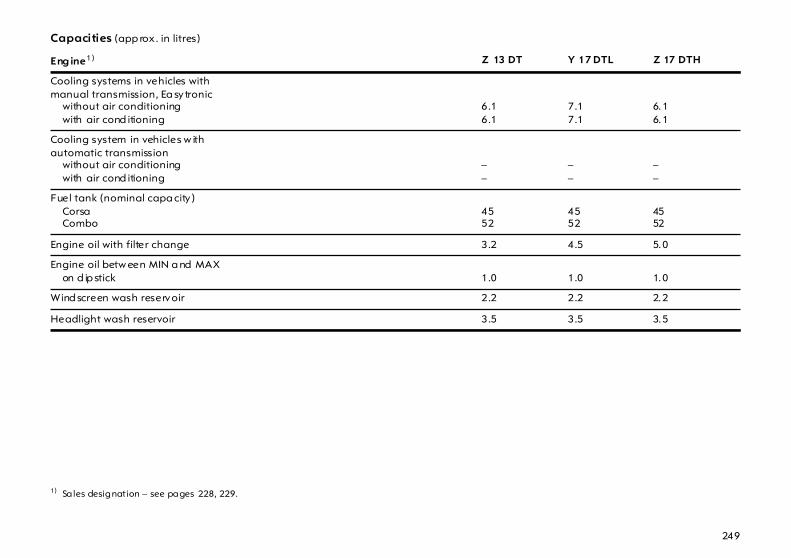
249
Capacities (app rox . in litres)
Eng ine1)
1) Sa les designation – see pages 228, 229.
Z 13 DT Y 17 DTL Z 17 DTH
Cooling systems in vehicles withmanual transmission, Ea sytronic
without air conditioningwith air cond itioning
6.16.1
7.17.1
6.16.1
Cooling system in vehicles w ithautomatic transmission
without air conditioningwith air cond itioning
––
––
––
Fuel tank (nominal capa city )CorsaCombo
4552
4552
4552
Engine oil with filter change 3.2 4.5 5.0
Engine oil betw een MIN a nd MAXon d ip stick 1.0 1.0 1.0
Wind screen wash reservoir 2.2 2.2 2.2
Headlight wash reservoir 3.5 3.5 3.5
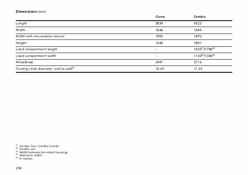
250
Dimensions (mm)
Corsa Comb o
Length 3839 4322
Width 1646 1684
Width with two exterior mirrors 1955 1892
Height 1440 1801
Loa d compartment length – 10201)/17802)
1) Co mbo Tou r, Combo Com bi. 2) Co mbo van
Loa d compartment width – 11203)/13004)
3) Width betw een th e wheel hou sin gs. 4) Maximum width.
Wheelb ase 2491 2716
Turning c ircle diam eter, wall to wall5)
5) In metres.
10.45 11.25

251
Mounting dim ensions oftowing equipment withremovable coupling ball bar,Corsa All dimensions relate to trailer towing equipm ent app roved b y Vauxhall.
Dimension mm
A 330.5
B 649
C 465
D 430
E 71.5
F 81.5
G 487.5
H 470.5
I 173
J 485
K 120
We recom mend hav ing tow ing equip-ment retrofitted by a Va uxha ll Autho-rised Rep airer.

252
Mounting dim ensions oftrailer hitch withrigid coupling ball bar,Combo All dimensions relate to trailer towing equipm ent app roved b y Vauxhall.
Dimension mm
A 71
B 929
C 515
D 506.3
E 274.3
F 149
G 401.7
H 384
I 398
We recom mend hav ing tow ing equip-ment retrofitted by a Va uxha ll Autho-rised Rep airer.

253

254
Index A
AB S (Anti-lock Brake System ).. ..... .... ..... 154Ac cessories. ..... .... ..... .... ..... ....93, 95, 98, 174Ac cessory socket ..... .... ..... .... .... ..... .... ..... .. 75Aerial .. .... .... ..... .... ..... .... ..... .... .... ..... .... ..... .. 48Air intake.... ..... .... ..... .... ..... .... .... ..... .... ..... 124Air recirculation system .... .... .... ..... .114, 123Air vents . .... ..... .... ..... .... ..... .... .... ..... .... ..... 115Airba gs... .... ..... .... ..... .... ..... .... .... ..... .... ..... .. 84Ala rm .. .... .... ..... .... ..... .... ..... .... .... ..... .... ..... .. 62Alterna tor ... ..... .... ..... .... ..... .... .... ..... .... ..... .. 31Anti-corrosion service.. ..... .... .... ..... .... ..... 210Anti-freeze . ..... .... ..... .... ..... .... .... ..... .... ..... 214Anti-freeze protection. ..... .... .... ..... .214, 218Anti-knock q ua lity of fuel .... .... ..... .... ..... 142
Octane number.... .... ..... .... .... ..... .... ..... 228Anti-theft lock
Alloy wheels .... ..... .... ..... .... .... ..... .... ..... 181Anti-theft protection ... ..... .... .... ..... .... ..... .. 24Aq ua planing ... .... ..... .... ..... .... .... ..... .... ..... 158Ashtray ... .... ..... .... ..... .... ..... .... .... ..... .... ..... .. 76Automatic anti-da zzle interior mirror ... .... 7Automatic climate control system ... ..... 119Automatic tra nsmission ... .... .... ..21, 22, 132
Control indicator.. .... ..... .... .... ..... .... ..... 134Driving programm es .... .... .... ..... .... ..... 134Fault.... .... ..... .... ..... .... ..... .... .... ..... .... ..... 136Interruption of power supply .... .... ..... 137Kic kdown ..... .... ..... .... ..... .... .... ..... .... ..... 135Selector lever... ..... .... ..... .... .... ..... .... .21, 22Winter programm e.. ..... .... .... ..... .... ..... 134
Automatic wiping .... .... ..... .... .... ..... .... ..... .. 18
B
Battery .. ..... .... ..... .... .... ..... .... ...139, 218, 247Interruption of power supply .. .... ..... .56, 104, 130, 137
Before starting off .. .... ..... .... ..... .... ..... .... ... 22Belt tensioners .... .... .... ..... .... ..... .... ..... .... ... 80Bleeding, diesel fuel system .... .... ..... .... . 170Bonnet ... ..... .... ..... .... .... ..... .... ..... .... ..... .... ... 63Brake servo unit.. .... .... ..... .... ..... .... ..... .... . 153Brake system . ..... .... .... ..... .... ..... .... ..... .... . 152Brakes.... ..... .... ..... .... .... ..... .... ..... .... ..... .... . 152
ABS .... ..... .... ..... .... .... ..... .... ..... .... ..... .... . 154Brake fluid .. ..... .... .... ..... .... ..... .... ..... .... . 227Brake lights ..... .... .... ..... .... ..... .... ..202, 203Brake servo unit.. .... ..... .... ..... .... ..138, 153Foot brake.. ..... .... .... ..... .... ..... .... ..... .... . 153Hand brake..... .... .... ..... .... ..... .... ..... .... . 154
Bulb replacem ent ... .... ..... .... ..... .... ..... .... . 194Bulbs.. .... ..... .... ..... .... .... ..... .... ..... .... .... 98, 194

255
C
Ca pacities ... .... ..... .... ..... .... ..... .... .... .248, 249Ca r Pass... .... .... ..... .... ..... .... ..... .... .... ..... .... .... 4Ca re .... ..... .... .... ..... .... ..... .... ..... .... .... ..... .... 221Ca ta lytic converter .. ..... .... ..... 144, 147, 170Central locking system . .... ..... .... .... .....52, 54Centre console lighting .... ..... .... .... ..... .... 101Changing the remote control b attery.. .... .... ...53, 247
Changing ty re/w heel type..... .... .... ..... .... 156Changing wheels . .... ..... .... ..... .... .... ..... ....179Child restraint systems . .... ..... .... .... .....95, 98Child safety locks . .... ..... .... ..... .... .... ..... .... ..50Child safety seats .... ..... .... ..... .... .... ..... .... ..95Ciga rette lig hter... .... ..... .... ..... .... .... ..... .... ..75Clim ate control system . .... ..... .... .... ..... ....119Clock ... ..... .... .... ..... .... ..... .... ..... .... .... ..... .... ..35Clutch operation .. .... ..... .... ..... .... .... ..... .... 139CO2 em issions. ..... .... ..... .... ..... .... .... ..... .... 231Code numbers. ..... .... ..... .... ..... .... .... ..... .... .... 4Coin holder .. .... ..... .... ..... .... ..... .... .... ..... .... ..77Cold start . .... .... ..... .... ..... .... ..... .... .... ..... ....139
C (continued)
Contra st.. .... ..... .... ..... .... ..... .... .... ..... .... ..... .. 42Control indica tor
ABS (Anti-lock Brake System) ... .... ..... 155Airbag. .... ..... .... ..... .... ..... .... .... ..... .... ..... .. 89Engine electronics .... ..... .... .... ..... .... ..... 146Exhaust ... ..... .... ..... .... ..... .... .... ..... .... ..... 146Imm obiliser.. .... ..... .... ..... .... .... ..... .... ..... .. 51TC (Traction Control system) .... .... ..... 148Transm ission ... ..... .... ..... .... .... ..... .... ..... 134
Control indica tors .... .... ..... .... .... ..... .... .12, 29belt tensioners. ..... .... ..... .... .... ..... .... ..... .. 81EPS (Electric Power Steering) .... .... ..... .. 32
Coolant... .... ..... .... ..... .... ..... .... .... ..... .... ..... 214Coolant level ... .... ..... .... ..... .... .... ..... .... ..... 215Coolant temp erature d isplay .. ..... .... ..... .. 36Coolant thermometer.. ..... .... .... ..... .... ..... .. 36Correcting time ... ..... .... ..... .... .... ..... .... ..... .. 41Coupling socket load .. ..... .... .... ..... .... ..... 166Courtesy light.. .... ..... .... ..... .... .... ..... .... ..... 101Courtesy lights
Bulb replacem ent .... ..... .... .... ..... .... ..... 206Cruise control .. .... ..... .... ..... .... .... ..... .... ..... 150Curtain airbags... ..... .... ..... .... .... ..... .... ..... .. 87
D
Data .. .... ..... .... ..... .... .... ..... .... ..... .... .... 51, 226Date... .... ..... .... ..... .... .... ..... .... ..... .... ..... .... ... 38Daytim e running lights ... .... ..... .... ..... .... ... 99Decommissioning ... .... ..... .... ..... .... ..... .... . 220Demisting a nd Defrosting
With the air conditioning system . .... .118Demisting a nd defrosting
Windows . .... ..... .... .... ..... .... ..... .... ..... .... .117with autom atic climate control system .... ..... .... ..... .... . 121
Diesel fuel filter ... .... .... ..... .... ..... .... ..... .... . 214Diesel fuel system ... .... ..... .... ..... .... ..170, 214Dimensions. .... ..... .... .... ..... .... ..... .... ..... .... .250Dipped beam. ..... .... .... ..... .... ..... .... ..... . 15, 99
Bulb replacement ... ..... .... ...194, 199, 201Display .. ..... .... ..... .... .... ..... .... ..... .... ..... .... ... 37Display m ode. ..... .... .... ..... .... ..... .... ..... .... ... 42Door locks .. .... ..... .... .... ..... .... ..... .... .... 50, 224Door-to-d oor light function ..... .... ..... .... ... 16Door-to-d oor lighting. ..... .... ..... .... ..... .... ... 16Driving ab road ... .... .... ..... .... ..... .... ..142, 209
Head lig hts.. ..... .... .... ..... .... ..... .... ..... .... . 102Toll system s..... .... .... ..... .... ..... .... ..... .... ... 48
Driving hints... ..... .... .... ..... .... ..... .... ..... .... . 138

256
E
Ea sytronic .... .... ..... .... ..... .... ..... .... .... ...20, 126driv ing programmes . .... ..... .... .... ..... ....127fault. ..... .... .... ..... .... ..... .... ..... .... .... ..... .... 130Interrup tion of power sup ply .... ..... .... 130Kickdown . .... ..... .... ..... .... ..... .... .... ..... .... 128Selector lever .... .... ..... .... ..... .... .... ...20, 126winter programme .... .... ..... .... .... ..... .... 128
Ec onomical driving .. ..... .... ..... .... .... .138, 140Electric folding roof . ..... .... ..... .... .... ..... .... 107Electric folding sun roof ... ..... .... .... ..... .... 109Electric power steering . .... ..... .... .... ..... .... ..32Electric sun roof ... .... ..... .... ..... .... .... ..... .... 106Electric windows... .... ..... .... ..... .... .... ..... .... 104Electrical system .. .... ..... .... ..... 188, 219, 247Electronic components . .... ..... .... .... ..... ....219Electronic immobiliser... .... ..... .... .... ..... .... ..51Electronic Stability Program ..... .... ..... ....149Ellipsoidal headlight system . .... .... ..... ....199
E (continued)
Engine c od e .... .... ..... .... ..... .... .... ..... .228, 229Engine c ontrol indicator... .... .... ..... .... ..... 146Engine oil .... ..... .... ..... .... ..... .... .... ..... .... ..... 212Engine oil c hange .... .... ..... .... .... ..... .... ..... 213Engine oil c onsumption.... .... ..212, 228, 229Engine oil filter .... ..... .... ..... .... .... ..... .... ..... 213Engine oil level .... ..... .... ..... .... .... ..... .... ..... 212Engine speed .. .... ..... .... ..... .... .... ..... .... ..... 139Engine w ash .... .... ..... .... ..... .... .... ..... .... ..... 224Environmental protection .... ..212, 213, 221EPS. ..... .... .... ..... .... ..... .... ..... .... .... ..... .... ..... .. 32ESP (Electronic Stab ility Prog ra m).... ..... 149Exhaust control indicator . .... .... ..... .... .....146Exhaust gases . .... ..... .... ..... .... .... ..... ...22, 147Exhaust system ... ..... .... ..... .... .... ..... .... ..... 147Exterior mirrors ... ..... .... ..... .... .... ....8, 97, 114
F
Fan .... .... ..... .... ..... .... .... ..... .... ...113, 211, 212Fault .. .... ..... .... ..... .... .... ..... .... ..... .... ..... .... . 104Filling station
Capac ities .. ..... .... .... ..... .... ..... .... ..248, 249Engine oil level .... .... ..... .... ..... .... ..... .... . 212Fuel .... ..... .... ..... .... .... ..... .... ...142, 228, 229Ignition key ..... .... .... ..... .... ..... .... ..... .... .... ..4Opening the bonnet .... .... ..... .... ..... .... ... 63Tyre pressure .. .... .... ..... .... ..... .... ..... .... . 243Vehic le da ta .... .... .... ..... .... ..... .... ..226, 227Windscreen wash system ..... .... ..... .... . 218
First-aid kit . .... ..... .... .... ..... .... ..... .... ....98, 174Flat tyre. ..... .... ..... .... .... ..... .... ..... .... ..... .... . 184Fog lights ... .... ..... .... .... ..... .... ..... .... ..... .... . 101
Bulb replacement ... ..... .... ..... .... ..... .... . 202Fog tail light
Bulb replacement ... ..... .... ..... .... ..... .... . 202Fog tail lights. ..... .... .... ..... .... ..... .... ..... .... . 101Folding sun roof
Manual operation... ..... .... ..... .... ..108, 110Foot brake . .... ..... .... .... ..... .... ..... .... ..... .... .153Front p assenger airbag .. .... ..... .... ..... .... ... 84Fuel .... .... ..... .... ..... .... .... ..... .... ...142, 228, 229Fuel consum ption ... .... ..... .... ...140, 142, 230Fuel gauge . .... ..... .... .... ..... .... ..... .... ..... .... ... 36Fuel level .... .... ..... .... .... ..... .... ..... .... ..... .... ... 36Fuel system, diesel . .... ..... .... ..... .... ..... .... . 170Fuses . .... ..... .... ..... .... .... ..... .... ..... .... ..... .... . 188

257
G
Gears .. ..... .... .... ..... .... ..... .... ..... .... .... ..... .... ..20Genuine Vauxhall Parts and Accessories25Glasses compartment .. .... ..... .... .... ..... .... ..77Glove compartment ..... .... ..... .... .... ..... .... ..77Graphical information displa y.. .... ..... .... ..37Gross vehicle w eight ..... .... ..... .... .... ..... .... 234Gross vehicle w eight rating... .... .... ..... .... 234
H
Halogen headlight system .... .... .... ..... .... 194Hand b rake. .... ..... .... ..... .... ..... .... .23, 24, 154Haza rd warning lights.. .... ..... .... .... ..... .... ..17Head restraints .... .... ..... .... ..... .28, 64, 65, 98Headlight flash .... .... ..... .... ..... .... .... ..... .... ..15Headlight range adjustment .... .... .100, 194Headlight sw itc h.. .... ..... .... ..... .... .... ..... 15, 99Headlight wash system .... ..... .... .... ...18, 218Headlights... .... ..... .... ..... .... ..... .... .... ..... .... ..15
Da ytime running lights. ..... .... .... ..... .... ..99Driv ing abroad . .... ..... .... ..... .... .... ..... ....102Fog lights. .... ..... .... ..... .... ..... .... .... ..... .... 101Reversing lights .... ..... .... ..... .... .... ..... .... 101Warning device .... ..... .... ..... .... .... ..... .... ..24
HeadlightsChanging bulbs.... ..... .... ..... .... .... .194, 199
Heated exterior mirrors .... ..... ...19, 114, 121
H (continued)
Heated front seats .. .... ..... .... .... ..... .... ..... 115Heated rear window ... ..... .... ....19, 114, 121Heating .. .... ..... .... ..... .... ..... .... .... ..... .112, 116
Seats ... .... ..... .... ..... .... ..... .... .... ..... .... ..... 115with automatic climate control system . .... .... ..... .... .....120With the air conditioning system.. ..... 112
Height ad justmentseat b elts ..... .... ..... .... ..... .... .... ..... .... ..... .. 82Steering wheel. ..... .... ..... .... .... ..... .... ..... .... 9
Horn.... .... .... ..... .... ..... .... ..... .... .... ..... .... ..... .. 17
I
Identifica tion plate. .... ..... .... ..... .... ..226, 227Ignition logic .. ..... .... .... ..... .... ..... .... ..... .... ... 43Ignition system ... .... .... ..... .... ..... .... ..211, 219Im mobiliser .... ..... .... .... ..... .... ..... .... ..... .... ... 51Information disp lay .... ..... .... ..... .... ..... .... ... 37Infotainment system .. ..... .... ..... .... ..... .... ... 37Inspection system ... .... ..... .... ..... .... ..... .... . 210Instrum ent illumination ... .... ..... .... ..... .... . 101
Bulb replacement ... ..... .... ..... .... ..... .... . 207Instrum ent panel .... .... ..... .... ..... .... ..... .... ... 10Instrum ents .... ..... .... .... ..... .... ...10, 29, 34, 35Interior m irror. ..... .... .... ..... .... ..... .... ..... .... .... ..7Interruption of power supply
Easytronic... ..... .... .... ..... .... ..... .... ..... .... . 130Electric sun roof .. .... ..... .... ..... .... ..... .... . 107Electric windows . .... ..... .... ..... .... ..... .... . 104Electronic S tability Program .... ..149, 219folding sun roof .. .... ..... .... ..... .... ..108, 110Selector lever lock ... ..... .... ..... .... ..... .... . 137
ISO-FIX .. ..... .... ..... .... .... ..... .... ..... .... ..... .... ... 95

258
J
Jac k . .... ..... .... .... ..... .... ..... .... ..... .... .... .178, 181Jump leads .. .... ..... .... ..... .... ..... .... .... ..... .... 170
K
Keyig nition lock . ..... .... ..... .... ..... .... .... ..... .... ..23Locking d oors... .... ..... .... ..... .... ...50, 52, 54Remove .... .... ..... .... ..... .... ..... .... .... ..... .... ..24Starting .... .... ..... .... ..... .... ..... .... .... .9, 23, 51
Key numbers, .. ..... .... ..... .... ..... .... .... ..... .... .... 4Keys .... ..... .... .... ..... .... ..... .... ..... .... .... ..... ..4, 50
L
Langua ge selection. ..... .... ..... .... .... ..... .... ..41Lashing eyes ... ..... .... ..... .... ..... .... .... ..... 69, 72Leather trim .... ..... .... ..... .... ..... .... .... ..... .... 223Light switch . .... ..... .... ..... .... ..... .... .... ..... .... ..15Lighting ... .... .... ..... .... ..... .... ..... .... .... ..... 15, 99
Driv ing abroad . .... ..... .... ..... .... .... ..... ....102Loa d compartment grille. ..... .... .... ..... .... ..72Loa ding ... .... .... ..... .... ..... .... ..... ...74, 165, 234Loa ding area
load ing . .... .... ..... .... ..... .... ..... .... .... ..... .... ..74Loa ding the vehicle. ..... .... ..... .... .... ..... .... ..74Loc k buttons ... ..... .... ..... .... ..... .... .... ..... .... ..50
L (continued)
Locking d oors . .... ..... .... ..... .... ....4, 50, 52, 54Locking from the inside ... .... .... ..... .... .50, 54Locks... .... .... ..... .... ..... .... ..... .... .... ..... .... ..... 224Lubricants .. ..... .... ..... .... ..... .... .... ..... .212, 227Luggag e comp artm ent ... .... .... ..... .... ..... .. 57
Bulb replacem ent .... ..... .... .... ..... .... ..... 206Cover .. .... ..... .... ..... .... ..... .... .... ..... .... ..... .. 70Extension ..... .... ..... .... ..... .... .... ..... .... .66, 68Lashing eyes ... ..... .... ..... .... .... ..... .... ..... .. 69Lighting .. ..... .... ..... .... ..... .... .... ..... .... ..... 102Loading .. ..... .... ..... .... ..... .... ....74, 165, 234Locking ... ..... .... ..... .... ..... .... .... ..... .... ..... .. 57
Luggag e comp artm ent cover . ..... .... ..... .. 70
M
M+S tyres .... ..... .... ..... .... ..... .... .... ..... .... ..... 159Main bea m. ..... .... ..... .... ..... .... .... ..... .... .15, 99
Bulb replacem ent .... ..... .... .... ..... .... ..... 196Control indicator.. .... ..... .... .... ..... .... ..... .. 31
Maintenance... .... ..... .... ..... .... .... ..... ... 25, 210Air conditioning system .... .... ..... .... ..... 125Anti-freeze protec tion .. .... .... ..... .... ..... 214Brakes. .... ..... .... ..... .... ..... .... .... ..... .... ..... 152Catalytic converter .. ..... .... .... ..... .... ..... 147Engine oil ..... .... ..... .... ..... .... .... ..... .212, 213Fuel consum ption .... ..... .... .... ..... .... ..... 141Tyre pressure... ..... .... ..... .... .... ..... .... ..... 157Tyres ... .... ..... .... ..... .... ..... .... .... ..... .157, 158Windscreen wiper .... ..... .... .... ..... .... ..... 216
Mirrors .... .... ..... .... ..... .... ..... .... .... ..... .... ... 7, 97Misted windows .. ..... .... ..... .... ..117, 118, 121Mobile telephone..... .... ..... .... .... ..... .... ..... .. 49
N
Num ber plate lightsBulb replacement ... ..... .... ..... .... ..... .... . 204
Num ber plate lighting .... .... ..... .... ..... .. 204OOctane numbers. .... .... ..... .... ...142, 228, 229Odometer... .... ..... .... .... ..... .... ..... .... ..... .... ... 34Oil change . .... ..... .... .... ..... .... ..... .... ..... .... .213Oil consumption . .... .... ..... .... ...212, 228, 229Oil filter change.. .... .... ..... .... ..... .... ..... .... . 213Oil level.. ..... .... ..... .... .... ..... .... ..... .... ..... .... . 212Operating temperature .. .... ..... .... ..... .... . 139Operation of the system . .... ..... .... ..... .... .117Outside tem perature g auge ... .... ..... .... ... 47Overrun . ..... .... ..... .... .... ..... .... ..... .... ..139, 141
P
Paintwork dam age. .... ..... .... ..... .... ..... .... . 223Parking distance sensor.. .... ..... .... ..... .... . 151Parking .. ..... .... ..... .... .... ..... .... ..... .... .... 24, 151Parking lights. ..... .... .... ..... .... ..... .... ..... .... ... 15
Bulb replacement ... ..... .... ..... .... ..... .... . 197Parking the vehicle. .... ..... .... ..... .... ..... .... ... 24Parts .. .... ..... .... ..... .... .... ..... .... ..... .... ..... . 25, 98Pedals.... ..... .... ..... .... .... ..... .... ..... .... ..... .... . 139Performance .. ..... .... .... ..... .... ..... .... ..... .... . 230Petrol . .... ..... .... ..... .... .... ..... .... ...142, 228, 229Pinking... ..... .... ..... .... .... ..... .... ..... .... ..... .... . 142Pollen filter . .... ..... .... .... ..... .... ..... .... ..... .... .124Power steering .... .... .... ..... .... ..... .... ..... .... . 138
tow ing ..... .... ..... .... .... ..... .... ..... .... ..... .... . 172Preheating . .... ..... .... .... ..... .... ..... .... ..... .23, 31Preheating sw itch ... .... ..... .... ..... .... ..... .... ... 23Pushing, towing .. .... .... ..... .... ..... .... ..... .... . 170

259
R
Radio .. ..... .... .... ..... .... ..... .... ..... .... .... ..... .... ..48Radio equipment (CB).. .... ..... .... .... ..... .... ..49Radio remote control ... .... ..... .... .... ..... .... ..52Rain sensor.. .... ..... .... ..... .... ..... ...18, 216, 222Reading lights. ..... .... ..... .... ..... .... .... ..... .... 102Rear light cluster.. .... ..... .... ..... .... .... ..... .... ..99
Bulb replacement. ..... .... ..... .... .... .202, 203Rear seat ba ckrests. ..... .... ..... .... .... ..... 66, 68Rear window wash system .... ...18, 218, 222Refuelling . .... .... ..... .... ..... .... ..... .... .... ..... ....143
Fuel filler cap .... .... ..... .... ..... .... .... ..... .... 143Relays . ..... .... .... ..... .... ..... .... ..... .... .... ..... .... 188Remote control
Central locking system . ..... .... .... ..... .... ..52Replacem ent keys ... ..... .... ..... .... .... ..... .... ..50Reversing lights.... .... ..... .... ..... .... .... ..... .... 101
Bulb replacement. ..... .... ..... .... .... .202, 203Roof load . .... .... ..... .... ..... ...74, 138, 141, 234Roof rack . .... .... ..... .... ..... .... ..... .... .... .141, 160Roof racks ... .... ..... .... ..... .... ..... .... .... .141, 160Running-in ... .... ..... .... ..... .... ..... .... .... ..... .... 138
Bra kes .. .... .... ..... .... ..... .... ..... .... .... ..... .... 152
S
Safeguard against unauthorised use ..4, 9, 24, 50, 51
Safety . .... .... ..... .... ..... .... ..... .... .... ..... .... ..... ..78Safety accessories ... .... ..... .... .... ..95, 98, 174Safety net ... ..... .... ..... .... ..... .... .... ..... .... ..... .. 71Safety systems .... ..... .... ..... .... .... ..... .... ..... .. 78Saving energy . .... ..... .... ..... .... .... ..... .... .....140Sea t belts ... ..... .... ..... .... ..... .... .... ..79, 82, 224Sea t height adjustm ent ... .... .... ..... .... ..... .... 6Sea t occupancy recognition .... ..... .... ..... .. 89Sea ts ... .... .... ..... .... ..... .... ..... .... .... ..... .... ..... .... 5
Extending the lugg age com partment .. ..... .... ..... .. 66hea ted .... ..... .... ..... .... ..... .... .... ..... .... ..... 115
Selector lever lock .... .... ..... .... .... ..21, 22, 133Self-diagnosis . .... ..... .... ..... ..81, 89, 148, 155Self-help . .... ..... .... ..... .... ..... .... .... ..... .... ..... 170
Automatic transm ission ... .... ..... .... ..... 136Electric windows... .... ..... .... .... ..... .... ..... 103Fold ing sun roof... .... ..... .... .... ..... .108, 110Information disp la y . ..... .... .... ..... .... ..... .. 38Radio remote control ... .... .... ..... .... ..... .. 52
Serv ic e Booklet.... ..... .... ..... .... .... ..... .... ..... .. 25
S (continued)
Service interval d isplay ... .... ..... .... .... 28, 210Service work ... ..... .... .... ..... .... ..... .... .... 25, 210S id e airba gs... ..... .... .... ..... .... ..... .... ..... .... ... 86S ig nal system. ..... .... .... ..... .... ..... .... ..... . 15, 17S lid ing doors .. ..... .... .... ..... .... ..... .... ..... .... ... 56Spare keys.. .... ..... .... .... ..... .... ..... .... ..... .... ... 50Spare w heel ... ..... .... .... ..... .... ..... .... ..176, 179Speed .... ..... .... ..... .... .... ..... .... ..... .... ..140, 141
Fuel consumption ... ..... .... ..... .... ..140, 141Speedometer . ..... .... .... ..... .... ..... .... ..... .... ... 34Sta rter switch. ..... .... .... ..... .... ..... .... ..... .... ... 51Sta rting the engine .... ..... .... ..... .... 9, 51, 170
Self-help ... .... ..... .... .... ..... .... ..... .... ..... .... . 170Steering column lock .. ..... .... ..... .... ..... ... 9, 24Steering w heel a djustment . ..... .... ..... .... .... ..9Steering w heel remote control .... ..... .... ... 26Stowa ge c om partments . .... ..... .... ..... .73, 77Sun roof. ..... .... ..... .... .... ..... .... ..... .... ..105, 106
fault ... ..... .... ..... .... .... ..... .... ..... .... ..... .... . 107Sun shade .. .... ..... .... .... ..... .... ..... .... ..105, 106Sun v isors ... .... ..... .... .... ..... .... ..... .... ..... .... ... 77System settings... .... .... ..... .... ..... .... ..... .... ... 40

260
T
Tachometer. .... ..... .... ..... .... ..... .... .... ..... .... ..34Tail lights . .... .... ..... .... ..... .... ..... .... .... ..... .... ..99
Bulb replacement. ..... .... ..... .... .... .202, 203Tailgate ... .... .... ..... .... ..... .... ..... .... .... ..... .... ..57Tank
Fuel gauge .. ..... .... ..... .... ..... .... .... ..... .... ..36TC (Traction Control System) ... .... ..... .... 148Technical d ata ..... .... ..... .... ..... .... .... ..... .... 226Tem perature regulation... ..... .... .... ..... .... 113Tem porary spare wheel ... ..... .... .... .159, 177The first 600 miles/1000 km .. .... .... ..... .... 138Tightening torque.... ..... .... ..... .... .... .183, 243Time .... ..... .... .... ..... .... ..... .... ..... .... .... ..... .... ..38Toll systems. .... ..... .... ..... .... ..... .... .... ..... .... ..48Tools ... ..... .... .... ..... .... ..... .... ..... .... .... ..... .... 178Towing ..... .... .... ..... .... ..... .... ..... .... .... ..... .... 172Towing eq uipm ent .. ..... .... ..... .... .... ..... .... 160Towing eye.. .... ..... .... ..... .... ..... .... .... .172, 174Traction Control system ... ..... .... .... ..... .... 148Trailer/caravan towing . .... ..... .... .... .138, 160
T (continued)
Tra nsmission, automatic . .... .... ..21, 22, 132Driving programm e. ..... .... .... ..... .... ..... 134Fault.... .... ..... .... ..... .... ..... .... .... ..... .... ..... 136Interruption of power supply .... .... ..... 137Kic kdown ..... .... ..... .... ..... .... .... ..... .... ..... 135Selector lever... ..... .... ..... .... .... ..21, 22, 133Selector lever loc k .... ..... .... .... ..... .... .21, 22Winter programm e.. ..... .... .... ..... .... ..... 134
Tra nsmission, Easytronic . .... .... ..... .... .....126driving p rogram mes ..... .... .... ..... .... ..... 127fault .... .... ..... .... ..... .... ..... .... .... ..... .... ..... 130Interruption of power supply .... .... ..... 130Kic kdown ..... .... ..... .... ..... .... .... ..... .... ..... 128Selector lever... ..... .... ..... .... .... ..... ... 20, 126winter p rog ra mme... ..... .... .... ..... .... ..... 128
Tread d epth .... .... ..... .... ..... .... .... ..... .... ..... 158Trip computer . .... ..... .... ..... .... .... ..... .... .27, 43Trip odometer . .... ..... .... ..... .... .... ..... .... ..... ..35Triple inform ation d isplay .... .... ..... .... ..... .. 37Turn signal lights ..... .... ..... .... .... ..... .... ..... .. 16Turn signals
Bulb replacem ent198, 200, 201, 202, 203Tyre c hains. ..... .... ..... .... ..... .... .... ..... .... ..... 159Tyre c ondition . .... ..... .... ..... .... .... ..... .... .....157Tyre p ressure .. .... ..... .... ..... .... .... ..... .157, 243Tyre repair kit . .... ..... .... ..... .... .... ..... .... .....184
U
Units of mea sure .... .... ..... .... ..... .... ..... .... ... 42Unlea ded fuel ..... .... .... ....142, 144, 228, 229Used oil . ..... .... ..... .... .... ..... .... ..... .... ..212, 213
V
Vauxhall alarm system ... .... ..... .... ..... .... ... 60Vauxhalll Service .... .... ..... .... ..... 25, 208, 209Vehicle care ... ..... .... .... ..... .... ..... .... ..... .... . 221Vehicle decom missioning ... ..... .... ..... .... . 220Vehicle identification numb er . .... ..... .... .227Vehicle recomm issioning .... ..... .... ..... .... . 220Ventilation . .... ..... .... .... ..... .... ...112, 116, 122

261
W
Warning buzzers.. .... ..... .... ..... .... .... ..... .... ..24Warning lig hts
ESP (Electronic Stability Program ) . ....149Warning triangle.. .... ..... .... ..... .... .... ...98, 174wash bottle, wind screen wa sh system .. 218Weights.... .... .... ..... .... ..... .... ..... .... .... ..... .... 234Wheels ..... .... .... ..... .... ..... .... ..... .... .... ..... .... 156Wheels, ty res ... ..... .... ..... .... ..... .... .... ..... .... 156Wind ow s.. .... .... ..... .... ..... .... ..... .... .... ..... .... 103
Demisting and defrosting . 117, 118, 121Wind screen wash system . ..... .... .... ...18, 218
Anti-freeze protection .. ..... .... .... ..... .... 218Capacities.... ..... .... ..... .... ..... .... .... .248, 249wash b ottle.. ..... .... ..... .... ..... .... .... ..... .... 218
Wind screen wiper .... ..... .... ..... .... .... ...17, 216
W (continued)
Winter modestarting-off aid ..... .... ..... .... .... ..... .128, 134
Winter op erationBattery .... ..... .... ..... .... ..... .... .... ..... .... ..... 139Coolant, a nti-freeze ..... .... .... ..... .... ..... 214Fuel consum ption .... ..... .... .... ..... .... ..... 141Fuel for diesel engines.. .... .... ..... .... ..... 142Heating... ..... .... ..... .... ..... .... .... ..... .... ..... 112Locks... .... ..... .... ..... .... ..... .... .... ..... .... ..... 224Tyre chains.. .... ..... .... ..... .... .... ..... .... ..... 159Window demisting and d efrosting ..... .... ..... .... ..117, 118, 121Windscreen wa sh system,anti-freeze p rotection .. .... .... ..... .... ..... 218
Winter prog ra mme.. .... ..... .... .... ..... .128, 134Winter tyres ..... .... ..... .... ..... .... .... ..... .159, 243
X
Xenon head lig ht systemBulb replacement ... ..... .... ..... .... ..... .... . 201

262