Corrosion Survey of Valdez Marine...
58
0 Final report: Corrosion Survey of Valdez Marine Terminal Contract Number 559.12.01 Submitted to: Tom Kuckertz, Project Manager Prince William Sound Regional Citizens’ Advisory Council 3709 Spenard Road Anchorage, AK 99503 Submitted by: R. Heidersbach Dr. Rust, Inc. 425 Buchanan Avenue, Unit 501 Cape Canaveral, FL 32920 [email protected] December 20, 2012
Transcript of Corrosion Survey of Valdez Marine...

0
Final report:
Corrosion Survey of Valdez Marine Terminal Contract Number 559.12.01
Submitted to:
Tom Kuckertz, Project Manager
Prince William Sound Regional Citizens’ Advisory Council 3709 Spenard Road
Anchorage, AK 99503
Submitted by:
R. Heidersbach Dr. Rust, Inc.
425 Buchanan Avenue, Unit 501 Cape Canaveral, FL 32920
December 20, 2012

1
Table of Contents
1.0 Executive summary ............................................................................................................ 2
1.1 Key Recommendations: ...................................................................................................... 3
2.0 Introduction ........................................................................................................................ 4
2.1 Acknowledgements ..................................................................................................... 4
2.2 DRI project team ......................................................................................................... 4
2.3 Objectives ................................................................................................................... 5
2.4 Changes in oilfield environments ................................................................................ 6
2.5 Project timeline ............................................................................................................ 6
2.6 Abbreviations and acronyms used in this report .......................................................... 7
3.0 Field observations .............................................................................................................. 7
3.1 Systems with corrosion concerns ................................................................................... 8
3.1.1 Corrosion under insulation (CUI) ............................................................................. 8
3.1.2 Internal Corrosion of Piping at the Valdez Marine Terminal .................................. 25
3.1.3 Corrosion monitoring using coupons and other means ......................................... 27
3.1.4 Reporting methods and training of field personnel ................................................ 33
3.1.5 Cathodic protection questions associated with industrial waste water lines ......... 36
3.1.6 Above-ground storage tanks ................................................................................. 37
3.2 Systems found to be generally in accordance with appropriate industry standards and regulatory requirements .......................................................................................................... 43
3.2.1 Structural integrity of berths and pilings ................................................................ 43
3.2.2 Protective coating systems used at the VMT ........................................................ 44
3.2.3 Fire fighting foam systems .................................................................................... 44
3.2.4 Cathodic protection ............................................................................................... 47
3.3 Subjects not considered in this report. ......................................................................... 49
4.0 Findings F1 through F15 and associated Recommendations .......................................... 50
2
1.0 Executive summary This project was undertaken in accordance with the Prince William Sound Regional Citizens Advisory Council (PWSRCAC) goals of minimizing the risks of hydrocarbon releases or other environmental damage associated with on-shore and berthing facility operations at the Alyeska Pipeline Service Company (APSC) Valdez Marine Terminal (VMT). Dr. Rust, Inc. (DRI), a corrosion and engineering consulting firm from Cape Canaveral, Florida was contracted for this project. A three-person team, all of whom have over 40 years of experience in corrosion control, was organized for the project. The project involved a review of records and procedures sent to the project team prior to a visit to VMT plus a three-day visit to the VMT from August 6-8, followed by an exit briefing with selected APSC personnel on Thursday, August 9, 2012. The results of this effort are summarized below, with detailed discussions in the main body of the report. Systems and procedures with significant corrosion concerns were:
Corrosion under insulation (CUI) Internal corrosion of piping at the Valdez Marine Terminal Corrosion monitoring using coupons and other means Reporting methods and training of field personnel Cathodic protection questions associated with industrial waste water lines Above-ground storage tanks
Systems and procedures found to be generally in accordance with appropriate industry standards and regulatory requirements were:
Structural integrity of berths and pilings Protective coating systems used at VMT Fire fighting foam systems Cathodic protection
3
1.1 Key Recommendations:
The VMT crude oil piping should have internal inspection (smart pigging) capabilities installed as soon as possible. This will allow periodic inspections on a timely basis and the ability to inspect for internal and external corrosion at the same time.
Until this smart-pigging capability is installed, the VMT should emphasize
inspection of all above-water piping systems to determine if corrosion under insulation (CUI) has occurred. This emphasis on above-water piping is in accordance with international guidelines on inspection priorities.
Repairs to external jacketing on piping systems necessitated by mechanical
damage during snow removal in 2012 and other damage from previous years should be implemented as soon as possible.
The instructions to contractor organizations conducting corrosion inhibitor
injection and corrosion coupon removal/replacement need to be updated to insure that corrosion-related observations such as wet piping exteriors are brought to the attention of the appropriate VMT decision makers.
The system of reporting maintenance problems to appropriate VMT personnel
and the responses back to the reporting personnel needs to be upgraded. The results of the summer 2012 inspections of Crude Oil Storage Tanks 13 and
14 need to be reviewed and compared with the recommendations in the 2002 Alaska Anvil report on tank roofs.

4
2.0 Introduction
2.1 Acknowledgements The following PWSRCAC personnel accompanied provided invaluable help in achieving the project goals:
Tom Kuckertz, Project Manager, Terminal Operations Anna Carey, Project Manager Assistant, Valdez Linda Swiss, Contingency Plan Project Manager
APSC Pipeline Services Company and contractor personnel who helped with this project include:
Barry Roberts, PWSRCAC Liaison, V MT Steve Lacatena, Integrity Management Engineering Supervisor, Anchorage Doug Fleming, Senior Operations Coordinator, VMT Tony Balowski, Sr. Program Support Engineer, VMT Clay Forsyth, Corrosion Engineer-Cathodic Protection, Anchorage Carl Wang, Corrosion Engineer—Inhibitors and Monitoring, Anchorage Tawna Beer-Burns, Coffman Engineers, Inc. Cecilia Sanchez, Baker Hughes
It should be noted that Lacatena and Forsyth both came to Valdez to assist with this project when the DRI project team was in Valdez.
2.2 DRI project team The Doctor Rust, Inc. project team included the following personnel:
Bob Heidersbach was the project leader and was responsible for internal and
external corrosion of piping, to include corrosion inhibitor treatment and corrosion

5
rate monitoring. Dr. Heidersbach has a PhD in metallurgical and materials engineering from the University of Florida and over 40 years of experience as a corrosion consultant. He is recognized as a NACE (National Association of Corrosion Engineers) certified corrosion specialist and is registered as both a metallurgical and a corrosion engineer by the State of California.
Kash Prakash was the team member responsible for marine terminals, above-
ground storage tanks, fire suppression systems, coatings and other non-metallic materials. Dr. Prakash has a PhD in chemistry from Florida State University and has spent over 40 years in the specialty chemicals and power industries.
Bob Guise is the team member most responsible for cathodic protection and
pipeline operations. He retired after over 40 years with the New Orleans utility system, working for the company that first introduced cathodic protection of buried pipelines as a standard means of corrosion control. He is also the team member most familiar with current, and past, regulatory agency guidelines and requirements associated with hazardous materials and pipeline operations. He has been a NACE-certified corrosion technologist since 1984.
2.3 Objectives The objectives of this project include:
Review recent corrosion-related projects and reports associated with VMT. Review appropriate State of Alaska, US government, and international
standards associated with corrosion control. Review APSC procedures as they relate to corrosion to insure compliance with
the appropriate guidelines listed in section 2.3.2 above. Visit the Valdez Marine Terminal to determine if the appropriate corrosion
control monitoring and inspection procedures are in effect. Because of the nature of the PWSRCAC charter, all of the work on this project emphasized corrosion control as it might affect hydrocarbon (crude oil and associated by-products) releases into the environment. While the VMT operates a power plant and other facilities that can corrode, the emphasis for this project was on the following equipment, the corrosion of which could result in releases of crude oil or associated chemicals into the environment:
Crude oil piping systems Crude oil storage tanks

6
Oily water piping systems Vapor recovery systems Above ground storage tanks Berth structures and pilings
The emphasis on this project was on procedures, and no attempt was made at detailed corrosion inspection of the VMT. We did, however, note corrosion whenever we saw it, and this report does discuss those instances of corrosion noted during our visit to the VMT. It was expected that corrosion-related inspections and maintenance would be underway by other contractors while the DRI team was at the terminal, and this was the case. We tried to minimize any disruption of these inspections or repair efforts.
2.4 Changes in oilfield environments As oilfields age, the corrosivity of the crude oil usually becomes more aggressive. Inspection and control efforts need to be increased in aging terminals, but decreased volumes of product usually result in lowered maintenance and inspection budgets at the same time that need for these efforts increase.
2.5 Project timeline
• Prior to July 31, 2012 – Request documentation prior to visit
• Anchorage, July 31-August 3, 2012 – Document review by one team member (Heidersbach)
• Valdez, August 6-9, 2012 – Monday
• Request escorts (same as previous week in Anchorage) • Request documents • Request access to Berth 4 (same as previous week request)
– Tuesday • Look at Berth 4—all of the team • Look at selected locations with APSC escorts
– Wednesday • Look at Berth 5
– Thursday • Exit briefing
• Draft report—due to PWSRCAC August 2012 • Final report after review

7
2.6 Abbreviations and acronyms used in this report AFFF Aqueous Film Forming Foam. Fire control foam used on berths and at
metering facilities API American Petroleum Institute APSC Alyeska Pipeline Service Company AST Above-ground storage tank ASTM Formerly the American Society for Testing and Materials), ASTM
International, formerly known as the American Society for Testing and Materials
CFR Code of Federal Regulations CUI Corrosion under insulation DRI Dr. Rust, Inc., a consulting firm based in Cape Canaveral, Florida,
specializing in corrosion control and related subjects ER Electrical resistance FFFP Film Forming FluoroProtein used for fire control in above-ground storage
tanks (ASTs) IWWS Industrial waste water system NACE Formerly the National Association of Corrosion Engineers NDT Non-destructive testing. Also called non-destructive inspection (NDI) or
non-destructive evaluation (NDE). The abbreviation NDT is most common and used for all purposes. The most common forms of NDT used for corrosion of piping and similar structures are visual inspection, radiography (usually X-ray) inspection (RT), and ultrasonic inspection.
PHMSA U.S. Dept. of Transportation Pipeline and Hazardous Materials Safety Administration
PWSRCAC Prince William Sound Regional Advisory Council RT Radiography, usually X-ray inspection SSPC The Coatings Society, the initials once stood for the name Steel Structures
Painting Council, but the organization's scope has expanded and the name has been changed.
TAPS Trans-Alaska Pipeline System VMT Valdez Marine Terminal UT Ultrasonic inspection or testing. Used to determine wall thickness in a
localized area of a metal structure.
3.0 Field observations This discussion is divided into discussions of the limited number of systems/procedures where corrosion control could be improved and of those systems where no significant corrosion concerns were identified after the three-day visit to the Valdez Marine Terminal.

8
APSC uses the term "pipeline" to refer to the Trans-Alaska Pipeline System (TAPS) which APSC operates to bring crude oil to the VMT. Once the crude oil enters the VMT, APSC uses the term “facilities piping” rather than "pipelines." APSC guidance on corrosion inspection and monitoring considers "facilities piping" to include both buried and above-ground piping.1 This report will use terms like "buried piping" to discuss piping on the VMT property. The industrial standards for pipelines issued by NACE - the Corrosion Society, API (American Petroleum Institute), ASTM (formerly the American Society for Testing and Materials), the U.S. Department of Transportation and similar organizations may apply to this buried piping. The Alaska Department of Environmental Conservation (ADEC) regulation on Oil Pollution and Other Hazardous Substance Pollution Control at 18 AAC 75 references these industrial standards for guidance on corrosion control, inspection, and monitoring.2-4
3.1 Systems with corrosion concerns The following discussion is about several subjects where significant improvements in corrosion control can be obtained at VMT.
Corrosion under insulation (CUI) Internal corrosion of piping at the Valdez Marine Terminal Corrosion monitoring using coupons and other means Reporting methods and training of field personnel Cathodic protection questions associated with industrial waste water lines Above-ground storage tanks
3.1.1 Corrosion under insulation (CUI)
The VMT has many insulated piping systems containing crude oil, oily water, and vapor. This means that corrosion underneath insulation must be addressed. This issue, while well-known in the chemical process industries, was not addressed adequately during the design of the VMT. NACE SP0198, the international standard on how to address CUI, was not published until 1998, many years after the VMT was designed, built, and put into operation.3
The Trans-Alaska Pipeline System (TAPS) and the VMT were designed and built at a time when the petroleum industry was not fully aware of the problems associated with CUI, so it is not surprising that inspection methods for controlling this problem were not addressed during design and construction. Current industrial practice suggests that insulated carbon steel piping must be protected from corrosion using protective coatings
9
rated for immersion service at the expected operating temperatures of the fluid in the piping or the piping exterior, whichever is most aggressive to coatings.3
A 2005 corrosion report done by Coffman Engineering for PWSRCAC made several references to corrosion under insulation, but did not indicate that this was a serious problem.5 The following quotes are from that report:
Page 12 of 39
..., “opportunistic inspections” are always performed when a pipe is exposed due to removal of insulation or excavation. SOP at the VMT is to have a CFE present at excavations to make and record a visual evaluation of exposed piping, conduit, and metal structure. If dents, dings, or other irregularities are observed then further investigation and repair is performed as warranted.
4) Following-Up on Corrosion Report Recommendations:... f. The 2002 PIT report recommends development of a new plan for investigation of piping under insulation. The 2003 report describes the new plan of using RT to screen for areas of >20% wall loss prior to UT testing. It should be mentioned that this is the new plan and so noted that the recommendation was followed through.”
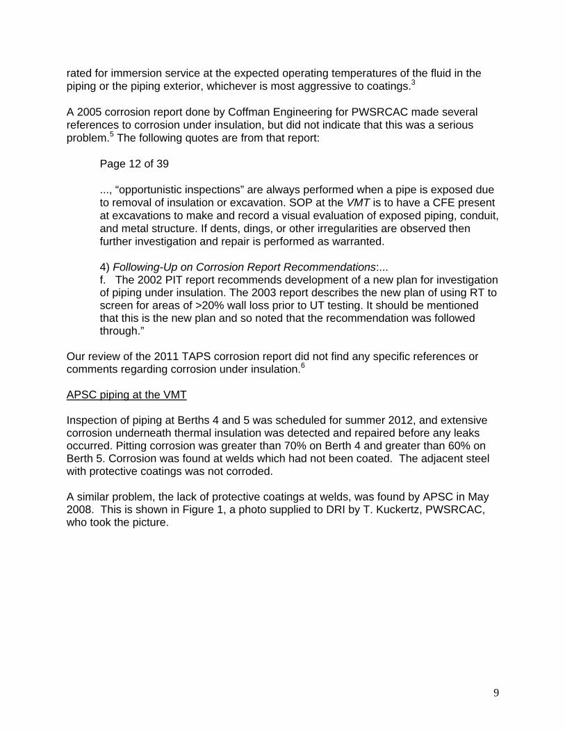
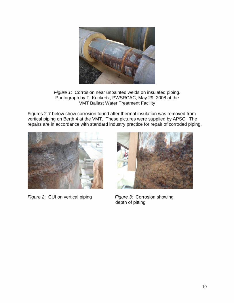
Our review of the 2011 TAPS corrosion report did not find any specific references or comments regarding corrosion under insulation.6 APSC piping at the VMT Inspection of piping at Berths 4 and 5 was scheduled for summer 2012, and extensive corrosion underneath thermal insulation was detected and repaired before any leaks occurred. Pitting corrosion was greater than 70% on Berth 4 and greater than 60% on Berth 5. Corrosion was found at welds which had not been coated. The adjacent steel with protective coatings was not corroded. A similar problem, the lack of protective coatings at welds, was found by APSC in May 2008. This is shown in Figure 1, a photo supplied to DRI by T. Kuckertz, PWSRCAC, who took the picture.
10
Figure 1: Corrosion near unpainted welds on insulated piping. Photograph by T. Kuckertz, PWSRCAC, May 29, 2008 at the
VMT Ballast Water Treatment Facility
Figures 2-7 below show corrosion found after thermal insulation was removed from vertical piping on Berth 4 at the VMT. These pictures were supplied by APSC. The repairs are in accordance with standard industry practice for repair of corroded piping.
Figure 2: CUI on vertical piping Figure 3: Corrosion showing depth of pitting

11
Figure 4: Vertical piping showing that Figure 5: Ultrasonic (UT) test grid for corrosion is associated with unpainted determining maximum wall loss at steel at welded joints corroded location
Figure 6: Epoxy repairs to corroded Figure 7: Steel sleeve installed over vertical piping repaired metal Figure 8 below, taken on Berth 5, shows a similar pattern of corrosion underneath insulation on vertical piping. The same lack of protective coating at welds shown in Figure 1 (2008 ballast water treatment facility) and Figures 2-7 (Berth 4) is apparent.

12
Figure 8: Corrosion under insulation (CUI) at unpainted welds on Berth 5 Note the ultrasonic (UT) inspection grid markings similar to those shown in Figure 5.
Finding F1: Figures 1-8 show that a pattern of corrosion at unpainted welds has been noted on piping under insulation since at least 2008. The corrosion discovered in 2012 was deep enough to warrant repair sleeves, and, equally important, it was on piping over the water. If the corrosion had not been discovered in time, it could have led to crude oil releases into Port Valdez. APSC reports that this condition was found as part of their planned CUI inspection project Z683 titled “VMT crude header external condition survey.” Sources of moisture underneath insulation weather-proofing
Figure 9 shows insulated piping at the VMT. Only the weather-proofing aluminum jacketing is visible.
Figure 9: Insulated piping systems at the air-to-soil interface on VMT
Carbon steel piping (or duplex stainless steel piping for the vapor recovery lines) is intended to be protected from external corrosion by immersion-grade coating systems rated for the intended operating temperatures. The coated steel piping is then surrounded by thermal insulation (plastic foam is used at VMT), and the outside of the

13
piping is covered with a moisture barrier (usually a metal jacket, most often sheet metal aluminum or galvanized steel). Buried pipes at the VMT run underground for hundreds of feet before being exposed to air (and atmospheric corrosion) where they are suspended on supports along the causeways leading to Berths 4 or 5. It is very difficult to inspect these buried locations for leaks in the external moisture barriers over the insulation. Liquid water or water vapor can enter into the piping systems at seams or defects in the sheet metal barrier, and this can lead to corrosion of the carrier pipe. Standard industrial practice for elevated piping is to locate the seams on the external barrier jacketing near the bottom (6 o'clock position) so that any moisture that might enter through defects in the seams will be allowed to drain out and cause minimal damage. The jacketing on the VMT causeways (and elsewhere at VMT) has seams not only at the 6 o'clock position. The large diameter of the piping at the VMT precludes having only one seam around the piping, and in most locations inspected in August 2012, one of the seams was located at the top (12 o'clock) position. Imperfections in the seams at this location can lead to water ingress into the piping system. Damage to Weather Barriers Damage to weather barriers is a common source of water ingress into insulation, and it is important to inspect and repair these weather barriers on a frequent basis. NACE SP0198 states:
In the long term, the weather barriers and vapor barriers break down or are damaged to the point that they can no longer keep the insulation dry. Therefore, maintenance and inspection of weatherproofing are essential to ensure the integrity of the insulation/fireproofing system.3
Figure 10 shows a defective seam at the 12 o'clock position on insulated piping along the causeway leading to Berth 5 at the VMT.
Figure 10: Open seam on insulation jacketing on piping leading to Berth 5 at the VMT

14
Other defects in the jacketing can also lead to moisture ingress. Openings in jacketing at attachment points for the crude oil and oily water lines on the causeway leading to Berth 5 are shown in Figures 11-13.
. Figure 11: Opening in weather Figure 12: Opening in weather jacketing on piping leading to Berth 5 jacketing on piping leading to Berth 5
Figure 13: Opening in weather jacketing on piping leading to Berth 5
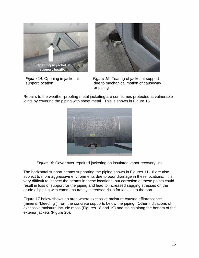
Figures 14 and 15 show similar openings where movement of the piping has caused damage to the sheet metal of the jacketing at the attachment openings.
15
Figure 14: Opening in jacket at Figure 15: Tearing of jacket at support support location due to mechanical motion of causeway or piping Repairs to the weather-proofing metal jacketing are sometimes protected at vulnerable joints by covering the piping with sheet metal. This is shown in Figure 16.
Figure 16: Cover over repaired jacketing on insulated vapor recovery line
The horizontal support beams supporting the piping shown in Figures 11-16 are also subject to more aggressive environments due to poor drainage in these locations. It is very difficult to inspect the beams in these locations, but corrosion at these points could result in loss of support for the piping and lead to increased sagging stresses on the crude oil piping with commensurately increased risks for leaks into the port.
Figure 17 below shows an area where excessive moisture caused efflorescence (mineral "bleeding") from the concrete supports below the piping. Other indications of excessive moisture include moss (Figures 18 and 19) and stains along the bottom of the exterior jackets (Figure 20).

16
Figure 17: Repaired insulation jacket indicated by top (vertical) arrow. Bottom (horizontal) area shows efflorescence indicating excessive moisture on the concrete
support at this location
Figure 18: Moss growing at Figure 19: Moss growing at another excessive moisture on thermal barrier location on the Berth 5 causeway jacketing on the Berth 5 causeway
Figure 20: Moisture indications at the bottom of insulated piping
17
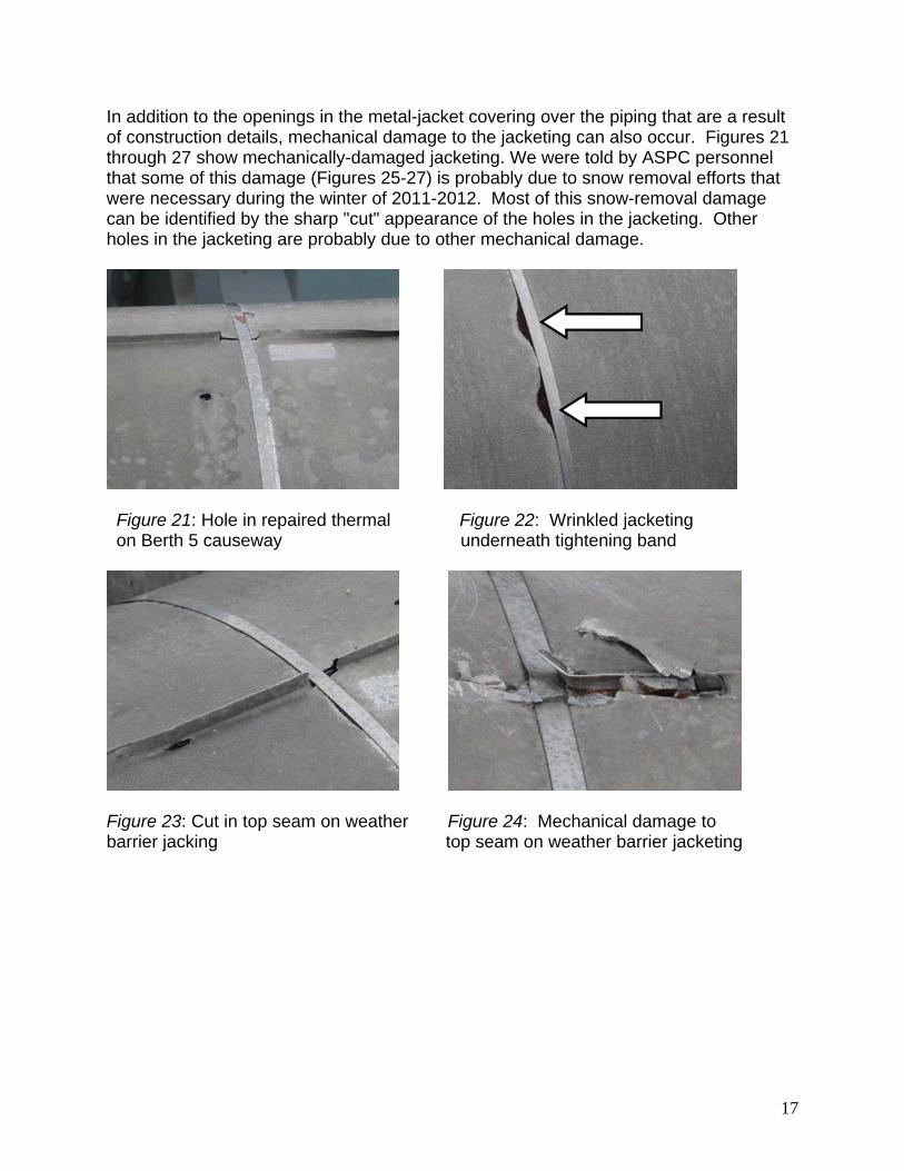
In addition to the openings in the metal-jacket covering over the piping that are a result of construction details, mechanical damage to the jacketing can also occur. Figures 21 through 27 show mechanically-damaged jacketing. We were told by ASPC personnel that some of this damage (Figures 25-27) is probably due to snow removal efforts that were necessary during the winter of 2011-2012. Most of this snow-removal damage can be identified by the sharp "cut" appearance of the holes in the jacketing. Other holes in the jacketing are probably due to other mechanical damage.
Figure 21: Hole in repaired thermal Figure 22: Wrinkled jacketing on Berth 5 causeway underneath tightening band
Figure 23: Cut in top seam on weather Figure 24: Mechanical damage to barrier jacking top seam on weather barrier jacketing

18
Figure 25: Snow removal damage Figure 26: Snow removal damage
Figure 27: Snow removal damage Water can be trapped between the foam insulation and the surface of metal piping. According to NACE SP0198-2010:
The more breaks there are in the equipment surface, the more likely that water will enter or bypass insulation and drain poorly from equipment. Therefore, high-quality, immersion-grade protective coatings must be used to protect steel and should be included in the design specifications.3
It should also be noted that the DRI team recorded the damage indicated in Figures 10-27 and that these damages were readily observable from well trafficked areas of the VMT. Numerous additional instances of such damage substantially similar to those presented in this report were observed but not recorded. APSC personnel pointed out snow-removal damage shown like that shown in Figures 25-27, but no actions seem to have been taken or planned to assess whether corrosion has resulted from the defects in the external weather jacketing on the over-water piping leading to Berths 4 and 5. Finding F2: While APSC has reported and provided multiple written procedures (OMS 4.60, 4.61, and 3.16) designed to report and address observed damages, many of the
19
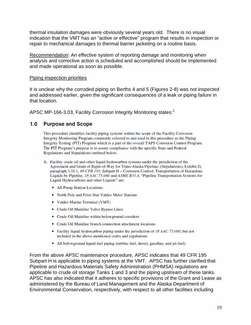
thermal insulation damages were obviously several years old. There is no visual indication that the VMT has an “active or effective” program that results in inspection or repair to mechanical damages to thermal barrier jacketing on a routine basis. Recommendation: An effective system of reporting damage and monitoring when analysis and corrective action is scheduled and accomplished should be implemented and made operational as soon as possible. Piping inspection priorities It is unclear why the corroded piping on Berths 4 and 5 (Figures 2-8) was not inspected and addressed earlier, given the significant consequences of a leak or piping failure in that location. APSC MP-166-3.03, Facility Corrosion Integrity Monitoring states:1
From the above APSC maintenance procedure, APSC indicates that 49 CFR 195 Subpart H is applicable to piping systems at the VMT. APSC has further clarified that Pipeline and Hazardous Materials Safety Administration (PHMSA) regulations are applicable to crude oil storage Tanks 1 and 3 and the piping upstream of these tanks. APSC has also indicated that it adheres to specific provisions of the Grant and Lease as administered by the Bureau of Land Management and the Alaska Department of Environmental Conservation, respectively, with respect to all other facilities including

20
piping at the VMT. Therefore, as indicated by APSC, it satisfies the requirements of 49 CFR 195 in a variety of ways depending on the regulator having cognizance. This is the reason that the apparently more restrictive requirements of PHMSA apply only to a small portion of the VMT facilities, namely, the incoming 48-inch mainline pipe into the terminal and the terminal’s relief system which is comprised of relief valves and 36-inch relief piping to crude oil storage Tanks 1 and 3 (designated for relief service). Consequently, this has resulted in certain portions of the over water piping not having been inspected since new construction (i.e., over 30 years). 49 CFR 195.583, the Federal guideline for corrosion control on liquid hydrocarbon pipelines, provides federally defined best-practice for atmospheric corrosion (corrosion of piping not buried or immersed in water):4
The following is noted from 49 CFR 195.583:
The above quotes are from a US government document intended to cover corrosion of liquid pipelines carrying hazardous liquids. These are best management practices and are generally what applies to most terminals. However, at the Valdez Marine Terminal it appears to only apply to Tanks 1 and 3 and the pipeline upstream of those tanks.
Most liquid pipelines are on shore.

21
The concerns listed in Paragraph 195.583(b) above are, in the order stated: Pipe at soil-to-air interfaces Under thermal insulation Under disbonded coatings (this statement assumes that the coating is visible to an inspector, i.e., the coating is not covered by thermal insulation) At deck penetrations Spans over water The definitions section of APSC MP-166-3.03 quotes 49 CFR 195.583 in defining atmospheric corrosion and then states:1
These inspections will normally take place in accordance with the required interval as prescribed in the above noted regulatory code sections for 49 CFR 195. (emphasis added)
The ordered listing of these areas of concern in the CFR should not be misconstrued to imply a rank-ordering or relative prioritization. It is the authors’ opinion that this misunderstanding has led some pipeline operators to incorrectly conclude that they should place priorities on inspecting piping (pipelines) at air-to-soil interfaces before inspecting under thermal insulation or under disbonded coatings before looking at deck penetrations or spans over water. There is no objective indication that such corrosion monitoring prioritization confusion exists at the VMT. Statements in the previous report submitted to PWSRCAC by Coffman Engineers, Inc.5 and the 2011 APSC TAPS report on facilities corrosion monitoring6 both emphasize corrosion monitoring at air-to-soil interfaces. This emphasis is in significantly more detail when compared to discussions of monitoring efforts relative to managing corrosion that may have occurred over water. The overarching idea is that triennial inspections of all five "particular attention" locations are required by the applicable federal regulation for onshore locations where those regulations are applicable. It is the authors’ opinion that annually inspecting over water piping when not required by specific regulation would certainly be a best management/engineering practice. Appendix C to the same federal liquid pipeline document gives guidance on how to identify high consequence areas.7

22
The above quote indicates that piping (pipelines) over navigable waters should be considered high-consequence areas. This means that priorities should be placed on inspecting all piping (pipelines) over the waters of Port Valdez. There is no objective reason to conclude that the corrosion found in 2012 is the deepest corrosion penetration to oil piping at the VMT. The entire system needs to be inspected as soon as possible. Follow-up inspections should also be conducted on an annual basis in accordance with the best-practice requirements applicable to the rest of the pipeline beyond the VMT as outlined in 49 CFR 195.583, as damage to the jacketing around the piping, which is the most probable source of leaks and water penetration to the piping, can occur at any time, even shortly after previous nearby leaks have been repaired. Finding F3: Depending on the regulatory authority having cognizance, the above quotations are partially applicable to the VMT. In those instances wherein the above quotations may not be regulatory, the Federal regulation should be considered a best management practice and lists two important ideas:
1. Onshore inspections must be conducted triennially. 2. Particular attention must be given to spans over water, in addition to the other
items requiring "particular attention." Regardless of the geographic and jurisdictional boundaries on the VMT where one set of regulations ceases to apply, the risks and consequences of corrosion to crude oil

23
piping on either side of that boundary are substantially identical. APSC does not seem to have any program designed to accomplish these triennial or other fixed-periodicity physical corrosion inspections for the VMT crude-oil piping, similar to those mandated by regulation for the piping upstream of the terminal. Finding F4: Absent a complete physical inspection of the VMT over-water crude-oil piping covered by external insulation, it is entirely possible that additional and deeper corrosion under insulation may exist at locations on Berths 4 and 5 that were not inspected as part of project Z683 during the summer of 2012. Finding F5: APSC has not embraced the best management practice of annual inspections of piping over water contained in 49 CFR 195 and contained in APSC MP-166-3.03 and applicable to other parts of the pipeline. Recommendation: APSC should take immediate steps to conduct the annual inspections outlined by CFR for piping over water and at the other inspection locations listed in 49 CFR 195.583 and 49 CFR 195 Appendix C. Comments on inspectability The above discussion is intended to be a strong argument for changes in how APSC identifies priorities for corrosion under insulation inspection. Corrosion under insulation is recognized worldwide in the marine terminal, petroleum, and other industries. Figure 28 shows locations where moisture ingress and resulting corrosion are likely to occur in elevated insulated piping systems. The locations shown in Figure 28 are similar to locations discussed in NACE SP0198, the recognized industry standard for this problem.3 This standard was first adopted in 1998, many years after the VMT was designed and constructed, so it is not surprising that the original design for the VMT did not develop inspection and corrosion control measures considered standard by 2012.

24
Figure 28: Problem locations for insulated above-ground piping 8
Unfortunately, the most well-planned localized inspection program cannot be expected to identify the precise location where the greatest corrosion damage (most likely pitting corrosion) will occur. Figure 29 shows a pipe at the VMT where corrosion-caused leaks occurred only one year after non-destructive inspection (non-destructive testing) nearby failed to identify where the leak would happen.
Figure 29: Corrosion leaking on a pipe at the VMT Ballast Water Treatment Facility one year after the piping had passed a non-destructive inspection.
Figure 29 is from a briefing by T. Kuckertz to the PWSRCAC, 9/18/2006

25
Recommendation: A possible solution to the problem of inspecting for corrosion (to include CUI) on VMT piping is to alter the existing piping systems so that they can be inspected using "smart" inspection pigs. This would also allow for inspection for internal corrosion. This modification of the VMT is the most important recommendation in this report (See Section 4 below for this and other recommendations). Until the VMT pipes become internally inspectable, localized external inspection priorities, which require removal of the thermal insulation so that the pipe surfaces can be inspected, should emphasize piping systems over the port instead of on-shore. These locations have the greatest possibility of producing high-consequence leaks and environmental damage. Conducting annual inspections on above-water insulated piping would also put VMT in conformance with best management practices as outlined in federal hydrocarbon piping regulations. While not directly applicable to the VMT, it is likely that in the near future external corrosion direct inspection (ECDA) of buried piping may be required in accordance with NACE SP0502.9 APSC reports that their upcoming project W051 will address currently buried VMT piping and is expected to provide future inspection options.
3.1.2 Internal Corrosion of Piping at the Valdez Marine Terminal
The petroleum industry has found that many corrosion leaks in piping systems are due to internal corrosion. The predominant corrosion leak mechanism is pitting corrosion for carbon steel piping, although other forms of corrosion such as the various forms of environmental embrittlement (stress corrosion cracking, hydrogen embrittlement, etc.) are also possible sources of leaks. In most stress-related corrosion fractures, cracking does not occur from high pressure inside the pipe. APSC MP-166-3.02, Internal Corrosion Investigation and Monitoring Program, describes the corrosion monitoring system guidelines in use at the VMT. Most of the corrosive fluid piping at the VMT is carbon steel, but the vapor recovery lines are duplex stainless steel (UNS S31803). The most likely internal corrosion mechanism for the stainless steel vapor recovery lines is stress corrosion cracking in various modes. In low pressure applications like the VMT vapor lines, stress corrosion cracking most often occurs in areas of locked-in residual forming stresses. For this reason, corrosion monitoring, and more importantly, corrosion inspection of vapor recovery piping needs to emphasize these typical failure modes and locations. Commercial inspection services that specialize in stress corrosion cracking detection should be retained for these lines. The same techniques cannot be used to check for cracking that are used for general wall thinning and pitting corrosion—the two most likely corrosion problems on carbon steel piping.

26
Corrosion Inhibitors Oil companies and crude oil marine terminals typically control internal corrosion on carbon steel piping using corrosion inhibitors, proprietary chemicals sold by various vendors that do not release the exact chemistries of their products. The comparative effectiveness of corrosion inhibitors, and of the oxygen scavengers and biocides that are also used to control corrosion, are monitored by the use of corrosion coupons or corrosion probes—pieces of metal inserted into piping systems downstream of the inhibitor/biocide injection ports and pulled on a periodic basis to determine if the corrosion inhibitors are effective in lowering corrosion rates. Corrosion rates in inhibited systems can be reduced to 5 to 10% of the corrosion rates that would be experienced if no inhibitors were used. The chemical treatment vendor treats the system on a monthly basis with a team that also services the pipeline.6 The teams treat the system from the northern end of the pipeline south to the VMT, and then return to the north end of the pipeline and repeat the process. This periodic batch treatment system of corrosion inhibitors is common in the pipeline and petroleum production industry. Continuous injection of corrosion inhibitors is also common. The coupon corrosion rates reported in the 2011 corrosion report are reported to be within accepted ranges in accordance with APSC and NACE guidelines.1, 6, 9 APSC (to include VMT) changed their corrosion inhibitor supplier in 2011, so there is no comparative information available on the effectiveness of the current inhibitors being used and whether or not the corrosion rates have been lowered due to the change in inhibitor suppliers.. We asked for inspection reports to determine if the piping in the vicinity of the injection quills had suffered erosion corrosion, a problem sometimes noted in other oilfield systems. This information has not been provided. Finding F6: No information is available on the comparative effectiveness of the current and previous chemical inhibitor programs. Recommendation: APSC should compare the coupon corrosion rates of the current and previous chemical treatment (to include corrosion inhibitors) suppliers. This information should appear in the 2012 TAPS report, which can use data from earlier reports to determine if the current chemical treatment is effective and to compare 2012 corrosion rates with those reported for previous years.

27
3.1.3 Corrosion monitoring using coupons and other means
The terms inspection and monitoring overlap, and their purposes are often confused.8 For the purposes of this report, the following definitions will be used:
Inspection is used to determine the condition of a system Monitoring is used as a tool for assessing the need for corrosion control or the
effectiveness thereof. The information available to the DRI team prior to our visit to the VMT led us to believe that problems might be found with corrosion inhibitor injection ports being too close to the coupon locations. We found no problems with the relative location of corrosion inhibitor injection ports and corrosion coupon locations. Guidance on the relative location of corrosion inhibitor injection ports and corrosion coupon monitoring locations is contained in APSC MP-166.3.02,10 which states:
The above practices warrant the following comments: 1. The ideas in this section are correct. Average corrosion rates are not of primary
interest. Most corrosion is localized in the dead legs and other low-flow rate locations described in this paragraph.
2. Choosing typical flow-rate locations for corrosion monitoring means that flow
rates are unlikely to represent the most corrosive conditions (see the previous paragraph comments on Item 1).
3. This is appropriate as written. An alternative idea would be to position the
coupon stations immediately upstream of the next injection port.
28
The idea of placing the corrosion coupons just upstream of the next inhibitor injection point has been suggested by another PWSRCAC consultant.11 The idea behind this alternative suggestion is to measure the corrosion rate at the farthest point from inhibitor injection, in other words, where the effectiveness of the corrosion inhibitor is likely to be least effective. This idea, which has some merit, does not account for the fact that the most severe corrosion is not expected to occur along the main stream of piping runs. The most severe corrosion is likely to be found in dead legs, underneath deposits (crevice or under-deposit corrosion), at welds or other surface roughness locations, etc.1,8
4. Several of the available coupon monitoring locations are not in use. APSC
reports that the unused and inactive coupon monitoring locations are on piping that has been abandoned or removed.
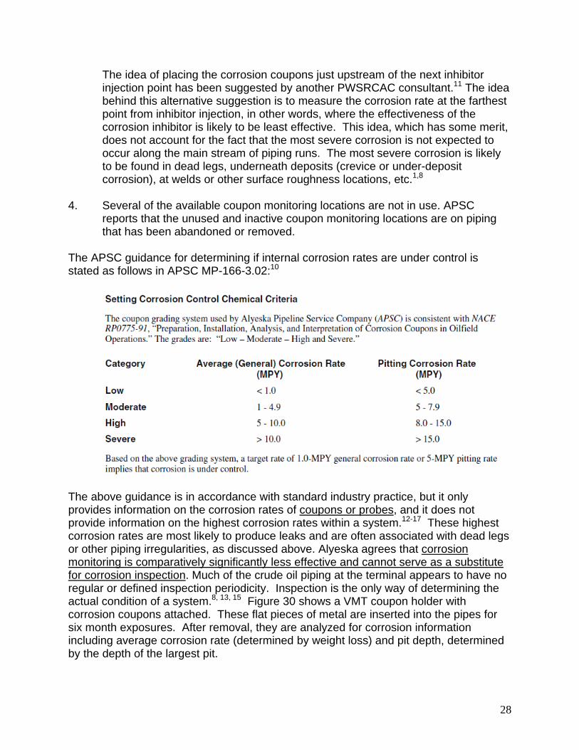
The APSC guidance for determining if internal corrosion rates are under control is stated as follows in APSC MP-166-3.02:10
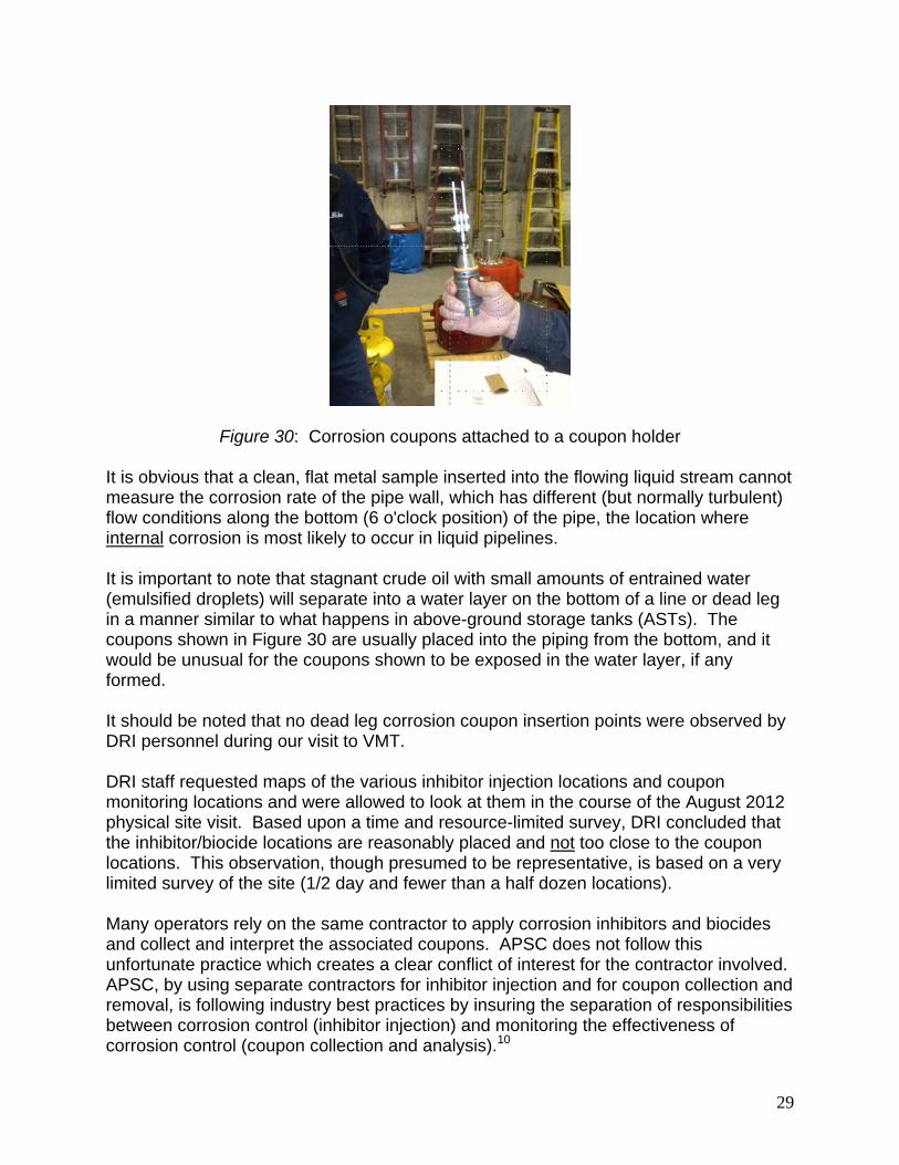
The above guidance is in accordance with standard industry practice, but it only provides information on the corrosion rates of coupons or probes, and it does not provide information on the highest corrosion rates within a system.12-17 These highest corrosion rates are most likely to produce leaks and are often associated with dead legs or other piping irregularities, as discussed above. Alyeska agrees that corrosion monitoring is comparatively significantly less effective and cannot serve as a substitute for corrosion inspection. Much of the crude oil piping at the terminal appears to have no regular or defined inspection periodicity. Inspection is the only way of determining the actual condition of a system.8, 13, 15 Figure 30 shows a VMT coupon holder with corrosion coupons attached. These flat pieces of metal are inserted into the pipes for six month exposures. After removal, they are analyzed for corrosion information including average corrosion rate (determined by weight loss) and pit depth, determined by the depth of the largest pit.
29
Figure 30: Corrosion coupons attached to a coupon holder
It is obvious that a clean, flat metal sample inserted into the flowing liquid stream cannot measure the corrosion rate of the pipe wall, which has different (but normally turbulent) flow conditions along the bottom (6 o'clock position) of the pipe, the location where internal corrosion is most likely to occur in liquid pipelines. It is important to note that stagnant crude oil with small amounts of entrained water (emulsified droplets) will separate into a water layer on the bottom of a line or dead leg in a manner similar to what happens in above-ground storage tanks (ASTs). The coupons shown in Figure 30 are usually placed into the piping from the bottom, and it would be unusual for the coupons shown to be exposed in the water layer, if any formed. It should be noted that no dead leg corrosion coupon insertion points were observed by DRI personnel during our visit to VMT. DRI staff requested maps of the various inhibitor injection locations and coupon monitoring locations and were allowed to look at them in the course of the August 2012 physical site visit. Based upon a time and resource-limited survey, DRI concluded that the inhibitor/biocide locations are reasonably placed and not too close to the coupon locations. This observation, though presumed to be representative, is based on a very limited survey of the site (1/2 day and fewer than a half dozen locations). Many operators rely on the same contractor to apply corrosion inhibitors and biocides and collect and interpret the associated coupons. APSC does not follow this unfortunate practice which creates a clear conflict of interest for the contractor involved. APSC, by using separate contractors for inhibitor injection and for coupon collection and removal, is following industry best practices by insuring the separation of responsibilities between corrosion control (inhibitor injection) and monitoring the effectiveness of corrosion control (coupon collection and analysis).10
30
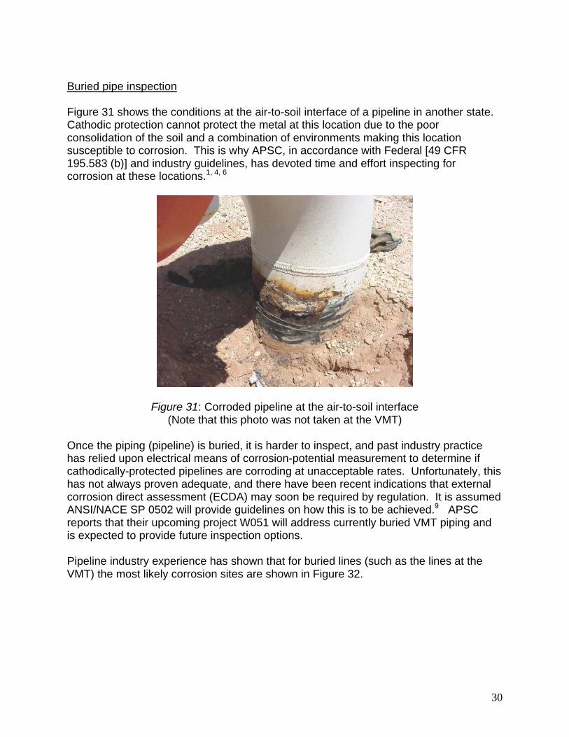
Buried pipe inspection Figure 31 shows the conditions at the air-to-soil interface of a pipeline in another state. Cathodic protection cannot protect the metal at this location due to the poor consolidation of the soil and a combination of environments making this location susceptible to corrosion. This is why APSC, in accordance with Federal [49 CFR 195.583 (b)] and industry guidelines, has devoted time and effort inspecting for corrosion at these locations.1, 4, 6
Figure 31: Corroded pipeline at the air-to-soil interface (Note that this photo was not taken at the VMT)
Once the piping (pipeline) is buried, it is harder to inspect, and past industry practice has relied upon electrical means of corrosion-potential measurement to determine if cathodically-protected pipelines are corroding at unacceptable rates. Unfortunately, this has not always proven adequate, and there have been recent indications that external corrosion direct assessment (ECDA) may soon be required by regulation. It is assumed ANSI/NACE SP 0502 will provide guidelines on how this is to be achieved.9 APSC reports that their upcoming project W051 will address currently buried VMT piping and is expected to provide future inspection options. Pipeline industry experience has shown that for buried lines (such as the lines at the VMT) the most likely corrosion sites are shown in Figure 32.

31
Figure 32: Radial locations where corrosion is most likely in a direct-buried oil pipeline8
For crude oil and oily water lines, the most likely corrosion location for internal corrosion is at the bottom (6 o'clock position). The corrosion coupon probes shown in Figure 30 will not detect corrosive conditions at this location. For the vapor recovery lines at the VMT, the most likely internal corrosion locations are near the top where condensation is likely to occur and near the bottom where water and solid deposits may collect. Gas condensates can be corrosive due to the presence of low-molecular-weight organic acids plus CO2 and H2S. External corrosion of buried steel lines (vapor or liquid) is most likely to occur at the 4 o'clock and 10 o'clock positions where the lack of soil consolidation is most likely to produce loose soil leading to a situation where accelerated corrosion at the air-to-water interface will occur.8 Other significant positions include 2 o'clock and 10 o'clock where longitudinal seam welds should be placed. Welds are locations where surface roughness, cracks, porosity, and minor variations in microstructure lead to increased corrosion susceptibility. We did not determine if the piping at the VMT had controls on the weld locations. This is an area of possible future inquiry.

32
While Figure 32 and the accompanying discussion identify likely locations for corrosion, best practice is to inspect the entire radius of buried pipelines. Modern methods of corrosion monitoring and inspection The coupon insertion and removal method of corrosion monitoring in use at the VMT is a long-established practice, but it has the same limitations that the localized non-destructive testing (NDT) procedures discussed for Figure 29 showed. The coupons can only measure the corrosivity of the local fluid at the locations where they are placed. In the decades since the VMT was constructed, a variety of other monitoring techniques have been developed.8, 15 Many operators use electrical-resistance (ER) probes to supplement their corrosion coupon monitoring. These probes have the ability to detect changes in corrosivity in less than one day (perhaps even minutes). This can be useful in detecting changes in corrosion rates due to process upsets that alter fluid compositions. Coupons can only identify if the total corrosion experienced over a six-month period was more or less corrosion than other exposures. Identification of why corrosion rates increased (if they do) may not be possible because the timing of when the corrosion happened is not precise. For marine terminals and pipelines, the most common process upset that affects corrosion is often the ingress of oxygen into the system. This is especially problematic for water lines (oily water at the VMT). Galvanic corrosivity monitoring might be appropriate for these lines.13
It is important to remember than any improvements in corrosivity monitoring cannot replace corrosion inspection. The two techniques are complementary. One cannot replace the other. The APSC guidelines on coupon placement clearly identify, as do NACE standards and PHMSA guidelines, that dead legs and other areas of restricted or unusual flow are locations where corrosion monitoring is most important.10, 15-17 These are also locations where inspection is most important, and, once again, monitoring in these locations cannot replace the need for inspection. Finding F7: Best industry practice is to locate the longitudinal welds at the 2 o'clock and the 10 o'clock positions on alternating piping joints. APSC reports they do not have a program or procedure in place to verify orientation of longitudinal seams on existing pipe, and that current and historical information has not demonstrated a significant or aggressive internal or external corrosion concern with longitudinal seams on TAPS piping. Whatever the locations of these longitudinal welds, these radial locations are locations where both internal and external inspections for possible corrosion should be concentrated. Recommendation: Future APSC external piping inspections should determine if the welds on large-diameter piping are alternated between the 2 o'clock and 10 o'clock

33
positions. Whatever the location of longitudinal welds, the location of these welds is an important location for corrosion inspections. A 360 degree inspection procedure is advised.
3.1.4 Reporting methods and training of field personnel
The DRI consultants noted a number of locations where maintenance was obviously needed. Questions posed to APSC personnel and to their contractors failed to identify a system for routinely reporting needed maintenance actions and for responses to these routine reports. Other marine terminal and pipeline operators have systems where anyone noticing a needed action can report it (using a computer connection in recent years), and they will receive a notification when their suggestion has been acted upon. Typical responses might include a notice that corrective action has been either scheduled or accomplished. Subsequent to the site visit, APSC reported and provided copies of multiple written procedures (OMS 4.60, 4.61, and 3.16) and VMT civil surveillance procedure 10610 which are designed to report and address observed damage. Nevertheless, many of the thermal insulation damages were obviously several years old. Workers noticing and reporting the snow removal damage shown in Figures 25 through 27 would assume that someone, sometime, would take appropriate action to repair the damage. In the course of the site visit and conversations with attending APSC staff, DRI personnel were unable to identify where/when this corrective action, which would require inspection and repair work over water, would happen. The multitude of procedures coupled with a lack of a visibly effective and active feedback system for reporting needed maintenance can lead to a situation where personnel working in the VMT stop commenting on “apparently very low priority” maintenance actions, or, if they have reported the needed repairs, they might assume that the problem is "in the system" and will be taken care of at the "appropriate time." It is obvious that many of the situations with damaged weather barriers on insulated piping are over one year old. This over-one-year comment does not apply to the snow-removal damage, Figures 25 through 27, which is assumed to be a result of the winter 2011-2012 snow removal efforts. Figures 33 through 40 show corrosion inhibitor injection points and corrosion coupon points inspected by DRI and APSC personnel (in addition to local contractor escorts) on August 8 and 9, 2012. All of the inhibitor or corrosion coupon stations had excessive moisture dripping from the container boxes. The injector or coupon devices and, more importantly, the carrier pipes were always water wetted. These locations are seen monthly by the corrosion injection crews and semi-annually by the corrosion-coupon crews, employees of two different contractors. There is no evidence that either contractor ever reported the wet piping to the APSC’s decision-making personnel. Perhaps this is due to a lack of guidance to do so by APSC. Guidance to both of these organizations should be provided that require this type of reporting as soon as possible.

34
Figure 33: Corrosion inhibitor injection Figure 34: UT inspection grid on carrier station 54-02A at station 54-02A
Figure 35: Exterior view of corrosion Figure 36: Close-up view of the inhibitor station 54-01E inhibitor injection device at station 54-01E
Figure 37: Water in coupon box C011B, which was full of water when opened on both August 7 and August 8, 2012

35
Figures 37 through 39 show the corrosion coupon box and the corrosion injection equipment at location C011B. A UT inspection grid pattern shown in Figure 34 is also apparent in Figure 38, indicating that both of these locations have been accessed, not only by the corrosion inhibitor and the corrosion coupon contractors, but also by a non-destructive inspection organization. Employees of any inspection organization should be cognizant of the significance of water under insulation, but, once again, it is not apparent this information was reported to the appropriate APSC and VMT decision makers.
Figure 38: UT grid pattern on carrier Figure 39: Corroded corrosion inhibitor pipe at location where water was noted. coupon injection point. The carrier pipe in this picture was wet when touched by DRI and APSC personnel on August 8, 2012. Figure 40 shows water droplets on the carrier pipe and the unavoidable void space between the carrier pipe and the rigid plastic foam insulation. Standing water can accumulate in this void space, and this has happened at this location as shown by the staining on the carrier pipe above the void space.
Figure 40: Water droplets and void spaces above a corrosion inhibitor injection point

36
APSC procedures and maintenance prioritization processes notwithstanding, Figures 33 through 40 are clear indications to DRI personnel that a reporting system for transferring information between responsible parties, the need for which was discussed earlier in this report, is not in active or in effective operation at the VMT. APSC guidelines for UT inspection (Figures 34 and 38) and for corrosion inhibitor injection or corrosion coupon insertion/removal crews do not advise the crews to report moisture ingress or corrosion damage. There is no information available in 2012 to determine if significant CUI of carrier pipes has occurred in locations near where the above photos were taken. More importantly, the question remains on whether or not significant corrosion, similar to the corrosion found on Berths 4 and 5 during the summer 2012 inspection and maintenance cycle, has occurred in the areas of "particular attention" listed in 49 CFR 195 that comprise a best practice standard recommending triennial inspection.4 Air-to-soil interfaces have been addressed in the past,5, 6 but the extensive over-water piping on the causeways has not been inspected on a routine or predictable recurring basis. As discussed above, the over-water locations are high-consequence locations where CUI or other corrosion damage could lead to releases of crude oil or other pollutants into Port Valdez. These above-water locations would be considered high-consequence areas by API RP 580, Risk-Based Inspection, and by 49 CFR 195.583 and require annual inspections in locations where compliance with PHMSA regulations is compulsory.4, 14 The only way to determine if CUI or other corrosion has occurred is full-line inspection for internal and external corrosion. The most efficient way of doing this would be to install in-line internal inspection capabilities (smart pigging capabilities). Finding F8: Corrosion inhibitor application crews and corrosion coupon removal crews lack explicit instructions to report excess moisture or other indications of corrosion or other problems that might be noted during their scheduled access to VMT piping locations. Recommendation: The APSC guidance document for corrosion inhibitor injection and for corrosion coupon retrieval and reporting (MP-166-3.02) should be altered to insure that moisture intrusion and other possible irregularities are effectively and reliably reported to the appropriate APSC and VMT personnel when observed.
3.1.5 Cathodic protection questions associated with industrial waste water lines
The industrial waste water lines are being repaired, primarily for internal corrosion, using a formed-in-place plastic liner system. The lines are made from ductile cast iron (nodular cast iron) with bell-and-spigot connections, which are not bonded across the joints except by the lead packing in the joints.
37
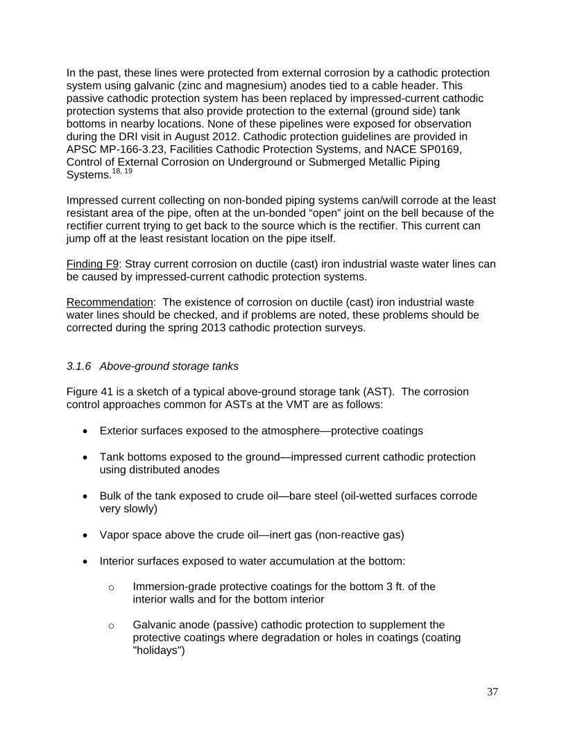
In the past, these lines were protected from external corrosion by a cathodic protection system using galvanic (zinc and magnesium) anodes tied to a cable header. This passive cathodic protection system has been replaced by impressed-current cathodic protection systems that also provide protection to the external (ground side) tank bottoms in nearby locations. None of these pipelines were exposed for observation during the DRI visit in August 2012. Cathodic protection guidelines are provided in APSC MP-166-3.23, Facilities Cathodic Protection Systems, and NACE SP0169, Control of External Corrosion on Underground or Submerged Metallic Piping Systems.18, 19 Impressed current collecting on non-bonded piping systems can/will corrode at the least resistant area of the pipe, often at the un-bonded “open” joint on the bell because of the rectifier current trying to get back to the source which is the rectifier. This current can jump off at the least resistant location on the pipe itself. Finding F9: Stray current corrosion on ductile (cast) iron industrial waste water lines can be caused by impressed-current cathodic protection systems. Recommendation: The existence of corrosion on ductile (cast) iron industrial waste water lines should be checked, and if problems are noted, these problems should be corrected during the spring 2013 cathodic protection surveys.
3.1.6 Above-ground storage tanks
Figure 41 is a sketch of a typical above-ground storage tank (AST). The corrosion control approaches common for ASTs at the VMT are as follows:
Exterior surfaces exposed to the atmosphere—protective coatings Tank bottoms exposed to the ground—impressed current cathodic protection
using distributed anodes Bulk of the tank exposed to crude oil—bare steel (oil-wetted surfaces corrode
very slowly) Vapor space above the crude oil—inert gas (non-reactive gas)
Interior surfaces exposed to water accumulation at the bottom:
o Immersion-grade protective coatings for the bottom 3 ft. of the interior walls and for the bottom interior
o Galvanic anode (passive) cathodic protection to supplement the protective coatings where degradation or holes in coatings (coating "holidays")

38
Figure 41: The different environments typical for an above-ground
crude oil storage tank
Two above-ground storage tanks, Tanks 13 and 14, used for crude oil storage, were in the process of API 653 condition inspections the week the DRI team visited the VMT.20 Vapor space corrosion control Corrosion in the vapor space of above-ground storage tanks can occur if the inerting gas allows corrosive condensation.21, 22 The steel on the interior ceilings of the tanks is unpainted, and corrosion control relies on the quality of inerting gases to prevent corrosion in this area. The system controlling the atmospheric pressure of the inerting gas in the tanks was not inspected as a part of the summer 2012 API 653 inspections of Tanks 13 and 14. The vapor control system may have been subject to other inspections not considered as a part of this report. This inerting gas system is the sole means of corrosion control in the vapor space which would otherwise be subject to atmospheric corrosion. The summer 2012 API 653 inspections of Tanks 13 and 14 should, however, determine if corrosion has occurred on the roof and associated support structures. Concerns about vapor space corrosion are discussed in a 2002 report by Alaska Anvil.21 The Anvil report discusses the consequences of two forms of corrosion:
Pitting corrosion Widespread general thinning of the roof structure

39
Pitting corrosion is a minor concern because localized penetrations of the roof would lead to minor leaks that can be patched, and no significant loss of the strength of the roof would result. General thinning of the roof could lead to possible localized roof collapse. Heavy snow loading could lead to dangerous conditions if snow-removal personnel were to fall through corrosion-thinned areas on the roof. This has not happened, but concerns about the condition of the roof remain.22 The 2002 Anvil report recommended:
Inspection of crude oil storage tank roofs using a 100% scan non-destructive examination (NDE) technique. NOTE: This is a more comprehensive inspection than standard API roof inspections, which emphasize the roof/shell interface. No information is available to the DRI team on the results of the 2012 inspection and on whether or not a 100% inspection of the roofs was conducted. The APSC document prescribing AST inspections does not require 100% inspection, so it is likely that this was not done during the summer 2012 inspections. It was not done in previous inspections in 2004 and 2009 (both inspections were conducted after the Anvil report made the 100% inspection recommendation), so it is unlikely that things changed during the 2012 inspection. 23
Painting roof interior surfaces (ceilings of the tanks) if corrosion is found to occur. Methods for repair of any locations where roof thinning due to corrosion has
occurred. Minimum roof plate thicknesses in accordance with the heavy snow loads
expected at the VMT. The same Anvil report discussed the necessity for increased roof plate thicknesses (compared to standards contained in API tank specifications) on the VMT storage tank roofs due to heavy snow loading and the possible effects of corrosion, which could lead to roof penetration or collapse.23 The report also recommended the minimum roof thickness for various radial locations (distance from the center of the roof). The recommended thicknesses are greatest near the edge of the roof (near the exterior walls). This is also the location where thinning due to corrosion is most likely.20, 21 Finding F10: A 2002 report by Anvil Alaska had numerous corrosion-related suggestions for AST roofs; the status/validity of these recommendations has not been determined. The APSC T-500, Paragraph 3.6 storage tank specification does not require 100% roof inspection, so it is unlikely that the summer 2012 API 653 inspections were as extensive as the 2002 Anvil report suggested. Recommendation: PWSRCAC should review the summer 2012 API 653 inspection reports with particular attention to those portions of the report which pertain to the roof

40
inspection. Roofs are a discretionary consideration, with direct inspection of internal roof structure omitted in many API 653 inspections, and the roofs of Tanks 13 and 14 may not have been inspected up to the level (100% of the roof) recommended by the 2002 Anvil report. Although API 653 does require roof inspections, such are, at best, perfunctory. Typically, APSC performs a visual inspection of the roof during an internal inspection using binoculars and occasionally during external inspections using very localized UT inspections for roof thickness. These types of inspections, however, fall short of revealing the true condition of the roof. The 2002 Anvil report also discusses the inadequacy of the API 650 and API 653 standards to address the minimum metal thickness for roofs with exceptionally-high snow loads. This should be readdressed when the results of the summer 2012 inspections of Tanks 13 and 14 are available. Depending on the results of the summer 2012 inspections, consideration should be given to painting the inside of the roof (ceiling), which would result in reducing internal corrosion to the negligible rates associated with coating degradation. Other aspects of above-ground storage tank corrosion control and inspection Figure 41 showed the cross-section of an above-ground crude oil storage tank. The steel in the tank is exposed to a variety of environments, and the corrosion control methods utilized at the VMT, in accordance with industry standards, depend on the location on the tank interior or exterior. The DRI team was not able to enter the tanks due to confined space safety considerations. The tanks were being inspected during the DRI visit, but no large entry holes had been cut. Figure 42 shows a crude oil tank interior during a previous inspection and repair. The paint on the lower portion of the vertical support columns as well as the interior tank bottom is obvious in this picture.
Figure 42: The interior of a large VMT crude oil storage tank during a previous inspection (Photo by T. Kuckertz, PWSRCAC)
41
The following APSC and API documents cover design, inspection and interior coatings for above-ground storage tanks.
APSC B-414, Interior Coating of Steel Tanks APSC T-500, Tank Corrosion Investigation This specification was modified in 2012 to include inspection and repair of fire-suppression foam distribution "spiders," which were repaired during the 2010 construction season in other tanks. API 653, Tank Inspection, Repair, Alteration, and Reconstruction API 650, Welded Tanks for Oil Storage
Observations on above-ground storage tanks, August 7, 2012 General observations
Tanks 1, 3, 13 and 14 were observed.
Tank 14 was in the process of being cleaned and inspected.
Tank 13 had been cleaned, inspected, and pending return to service.
Tanks 1 and 3 were visually observed from an elevation on the East Tank Farm Road.
Tanks 13 and 14 have been inspected in the past. Dr. Prakash requested a copy of inspection reports from APSC VMT personnel. APSC will provide the inspection reports when they become available. Dr. Prakash recommends a comparison of the earlier API 653 internal inspection report and the 2012 API 653 inspection report to gauge inspection parameters, especially on floor integrity (loss of metal). Tank 14 observations
There were several activities inside tank 14 due to scheduled cleaning and inspection. Manhole viewing indicated the following:
API 653 specification is followed for inspection. The tank floor was clean and devoid of any corrosion to the extent visible from
the opening. Several bags of corrosion products and debris were collected. The tank floor bottom was installed in 1998. A corrosion rate should be determined as a part of the API 653 inspection. This corrosion rate should be reviewed once the report on the results of the API 653 inspection are available.

42
The coating on the tank floor is Devoe Bar Rust 236, which is an appropriate
coating for this application. The tank columns had been painted 3 feet off the floor. Sediment and sludge build up on tank bottoms should be minimized to avoid fire
suppression piping plugging problems. Foam piping inside the tank appeared clean to the extent visible (API 570). The inside view of the tank showed no signs of any excessive items of concern to
the extent visible from one manhole. There should be a specification for a manhole gasket for the tank manhole. The tank roof area was not evaluated. The possibility of severe corrosion of the
roof should be determined. Roof areas should be subject to evaluation, especially around vapor nozzles and relief vents, if corrosion is found. Once again, the report of the 2012 API 653 tank inspections underway while the DRI team was in Valdez should be checked to see if roof corrosion was investigated. Additional details on this subject are contained in Section 3.1.6, Above-ground Storage Tanks.
Tank 13 observations Tank 13 was also being inspected during summer 2012. Additional above-ground storage tank comments All tank piping should be inspected in accordance with API 570 standards. Finding F11: The 2002 Anvil report recommended 100% roof inspection and greater metal thickness requirements than standard API recommendations. Recommendation: The results of the summer 2012 API 653 inspections of Tanks 13 and 14 should be compared with previous inspection reports. Particular attention should be concentrated on the roofs, which are subject to snow loading in excess of the loads assumed by API tank construction and inspection standards.

43
3.2 Systems found to be generally in accordance with appropriate industry standards and regulatory requirements The following areas of corrosion control were found to be in accordance with acceptable industry standards:
Berths and supporting structures to include submerged areas which are cathodically protected
Protective coatings in use at the VMT Aqueous film forming foam systems for fire suppression and control
Some aspects of cathodic protection. Minor areas of concern are discussed
above in Section 3.1.5.
3.2.1 Structural integrity of berths and pilings
The structural integrity of berths and pilings is addressed by two APSC procedures:
APSC MP-166-3.03.01, Facility Corrosion Integrity Monitoring and Implementation
APSC MP-166-3.21, VMT Facility Underwater Inspections
The 2011 facilities corrosion monitoring report includes a summary of the inspections of the berths and associated facilities.6 No areas of concern were noted.
The following comments pertain to the observations on the two berths that were visited by the DRI team in August 2012. Berth No. 5 was observed on August 8, 2012 Flange bolts on pipe carrying oil on the berth were corroded; this can lead to loss of metal on bolts, seizures, and break-off when using torque. A possible solution would be to thin coat flanges with lubricant such as Tectyl 846 from Shell Oil Co. Several major oil companies have adopted the practice of using fluorocarbon-coated bolts for anti-seizure properties with galvanizing underneath the fluorocarbon coating for corrosion control. APSC may wish to consider this option, which limits the need for cutting threaded fasteners, bolts, or nuts for maintenance or other removal. This procedure is acceptable for ASTM A193 B7 bolts, which we were told are commonly used at the VMT. The use of galvanizing or other metallic coatings is precluded on higher-strength fasteners due to concerns with hydrogen embrittlement.25-28 APSC

44
reports they do not lubricate certain bolts, especially over the water, to avoid the potential for a sheen to water resulting from precipitation runoff. Finding F12: Fasteners on Berths 4 and 5 can occasionally seize due to superficial corrosion. Recommendation: APSC may wish to consider using fluorocarbon coatings on ASME A193 B7 and similar fasteners, in accordance with best practice by other oil and gas companies. These fasteners can also be galvanized, although higher-strength fasteners, if used, cannot be galvanized due to hydrogen embrittlement concerns.
3.2.2 Protective coating systems used at the VMT
APSC has three specifications for tank coatings that were evaluated:
APSC B-408, Coatings for Marine Berths APSC B-414, Interior Coating of Steel Tanks APSC B-419, External Coatings for Facility Piping and Structural Steel Under
Insulation or Atmospheric Exposure Each of these specifications lists approved proprietary coating systems for use in the intended service. All of the listed materials are acceptable for corrosion control in accordance with accepted industry practice. Coating performance is dependent to a large extent on the proper surface preparation and profile of substrates as well as adhering to recommended application parameters. All coating operations must be conducted by a qualified and certified painting contractor familiar with NACE and SSPC guidelines. APSC uses third party coatings inspection organizations to verify that surface preparation and coatings application are in accordance with APSC and either NACE or SSPC guidelines. Finding F13: The APSC guidelines and practices for the use of protective coatings appear to be in accordance with accepted industry practices.
3.2.3 Fire fighting foam systems
The VMT has fire fighting foam systems in several areas. These systems are placed in strategic areas, and concentrated foam chemicals are stored in tanks associated with these areas.

45
Aqueous Film Forming Foam (AFFF) The AFFF is diluted and applied in a 3% concentration for firefighting operations, is designed for topical (from above the surface) applications, and is connected for potential application in the VMT metering buildings and on the loading berths. Several commercial products are available for this purpose and experience has shown that some of the ingredients in foam chemicals have the capability of initiating corrosion to steel surfaces on a long term basis. This can lead to corrosion of the carrier pipe from inside-out. The storage tanks for the AFFF chemicals prior to distribution are reinforced polymer composites (HDPE) chosen for this service. There was no indication of any corrosion problems when using the AFFF chemicals at the VMT. Film Forming FluoroProtein (FFFP) The FFFP is diluted and applied in a 4% concentration for firefighting operations, is designed for subsurface applications, and is connected for application in the VMT Crude oil storage tanks. There was no indication of any corrosion problems when using the FFFP chemicals at the VMT. Foam distribution piping Figure 43 shows the foam distribution piping systems for a typical above-ground storage tank. In the event of an incident, FFFP foam is mixed and distributed through a piping system to the bottom of the crude oil tanks using carbon steel piping. In recent years, inspections of Tanks 9 and 11 showed that the foam distribution "spiders" in these tanks had corroded, and the corrosion was repaired by using reinforcing sleeves during the 2011 construction season.6

46
Figure 43: Fire-foam distribution system in a typical VMT storage tank
APSC T-500, Tank Corrosion Investigation operating procedure was upgraded in early 2012 to require internal and external inspection of these 6 inch foam-distribution spiders flared to 10 inches at the end of the spider. This revised procedure was in use during the 2012 construction season for inspections and possible repairs to Tanks 13 and 14. The same document does not specify any inspection of the piping systems leading to these 6 inch lines. This appears to be an oversight. The 2012 T-500 document requires inspection of foam-distribution spiders during internal tank inspections (API 653 inspections). Paragraph 3.4.2 suggests that UT (ultrasonic) or RT (radiographic) inspection should normally be limited to the lower arc between the 3 o’clock and 9 o’clock positions unless the camera crawler indicates otherwise. The foam distribution systems to the storage tanks are manufactured by specialty suppliers using materials selected for this service. The foam distribution lines are shown in blue in Figure 43. APSC reports the foam distribution pipes are uncoated steel. The storage tanks for the FFFP chemicals prior to distribution are coated steel. APSC reports that these steel FFFP storage tanks are on a 10 year internal inspection cycle, were last inspected in 2012, and will be subjected to an external inspection in 2013. A conference call with a previous consultant retained by PWSRCAC on Thursday,

47
August 2, 2012 revealed no corrosion concerns on the foam handling and storage equipment by this "fire suppression" consultant. APSC reports that they conduct annual flow tests of the foam system. These tests ensure the foam skid is in full working order and is able to proportion the foam correctly. In this test, the foam is discharged through test ports rather than through the in-tank distribution system. A method to determine whether the internal foam piping in the crude oil storage tanks is free of corrosion should also be available. While APSC reports that an annual flow test is performed to ensure that the lines are not plugged, this is not the same as inspecting for corrosion. In fact, such testing would not reveal whether a spider is plugged if it had separated due to corrosion. Corrosion of the 20-inch carbon steel crude oil piping shown in Figure 43 was addressed in the revised 2012 version of APSC T-500, but there seems to be no similar inspection of the dedicated foam piping and handling equipment. All foam related piping, valves and delivery systems throughout the complex should have procedures for inspection. Finding F14: APSC T-500 Paragraph 3.4.2 suggests that UT (ultrasonic) or RT (radiographic) inspection should normally be limited to between the 3 o’clock and 9 o'clock positions unless the camera crawler indicates otherwise. Recommendation: The summer 2012 API 653 inspections of Tanks 13 and 14 should be reviewed to determine if any internal inspection can justify the recommendation in APSC T-500 Paragraph 3.4.2 that external RT and UT inspections (which can also detect internal corrosion) can be justified. Inspection of the piping between the FFFP chemical storage tanks and the mixing valve should also be done if this has not been covered by the summer 2012 API 653 tank inspections.
3.2.4 Cathodic protection
Cathodic protection is an electrical means of corrosion control. It is used at the VMT to minimize corrosion on the exterior of buried piping, submerged portions of the loading berths, and above-ground storage tank bottoms (both interior and exterior surfaces on the tank bottoms). The appropriate standards and guidelines associated with cathodic protection include:
NACE SP0169, Control of External Corrosion on Underground or Submerged Metallic Piping Systems
APSC MP MP-166-3.23, Facilities Cathodic Protection Systems
APSC MP-166-3.03, Facilities Corrosion Integrity Monitoring

48
APSC B-484, Sacrificial Cathodic Protection Above Ground Storage Tanks-Internal
APSC RO-245, Valdez Marine Terminal Cathodic Protection System
The following types of cathodically-protected structures were inspected by R. Guise, the DRI cathodic protection expert, accompanied by C. Forsyth, APSC cathodic protection subject matter expert, and Anna Carey, PWSRCAC.
Berth 5
Crude oil lines
Fire water lines
Industrial waste water
General comments on cathodically-protected steel piping and berth legs:
All cathodic protection potential readings were in accordance with the above-listed NACE standard and APSC guidelines.
It seems that almost all, if not all, underground piping is electrically tied together. All pipe to soil readings taken during this observation period were on/off
potentials using a copper/copper sulfate reducing electrode, unless otherwise stated.
Cathodic protection test stations have buried reference-electrode tubes in which
to insert the reference electrode for the pipe to soil readings.
APSC reports that all crude oil tanks currently in service have at least one reference electrode monitoring tube to make it possible to read the underside of the tank bottoms.
APSC reports that all crude oil tanks currently in service have at least one
permanent reference electrode installed under the tanks. The cathodic protection systems for the industrial waste water system (IWWS)
lines may have stray current problems associated with the bell-and-spigot joints of the ductile (cast) iron IWWS piping. This possible problem was discussed in Section 3.1.5.
Finding F15: The cathodic protection procedures and installations at the VMT seem to be in accordance with accepted industry practice and industrial standards with the

49
single exception of concerns with ductile (cast) iron IWWS piping, which are discussed in Section 3.1.5. Cathodic protection systems were recommended for firewater piping by the 2005 Coffman report.5 This seems to have been done, because the cathodic protection readings on these lines were within NACE guideline ranges. Recommendation: No recommendations for improved cathodic protection of equipment other than the ductile (cast rather than drawn) iron IWWS piping discussed in Section 3.1.5 are appropriate.
3.3 Subjects not considered in this report. Cured-in place linings to repair deteriorated (corrosion and other causes)
industrial waste water piping.
Selection/qualification method for gaskets and sealing materials used in piping systems
Packing systems for pumps—similar questions Digs, if any, to determine the condition of bell and spigot joints on ductile cast
iron piping used for industrial waste water Power generation system reliability and its affects on emergency power to fire
suppression and to cathodic protection systems Complete evaluation of secondary containment for AST
– 2 tank cells – Liner is approximately 34 years old, should be tested for permeability – Better liner materials are now available – Corrosion issues can affect stand-by capabilities

50
4.0 Findings F1 - F15 and Associated Recommendations This section of the report repeats the findings and recommendations discussed and listed in Section 3—Field Observations in this report. The major findings have been identified as F1 through F15. Findings and recommendations associated with individual findings have been organized in the following table.

51
Finding No.
Finding Recommendation
F1 Figures 1-8 show that a pattern of corrosion at unpainted welds has been noted on piping under insulation since at least 2008. The corrosion discovered in 2012 was deep enough to warrant repair sleeves, and, equally important, it was on piping over the harbor. If the corrosion had not been discovered in time, it could have led to crude oil releases into Port Valdez. APSC reports that this condition was found as part of their planned CUI inspection project Z683 titled “VMT crude header external condition survey.”
F2 While APSC has reported and provided multiple written procedures (OMS 4.60, 4.61, and 3.16) designed to report and address observed damages, many of the thermal insulation damages were obviously several years old. There is no visual indication that VMT has an “active or effective” program that results in inspection or repair to mechanical damages to thermal barrier jacketing on a routine basis.
A system of reporting damage and monitoring when analysis and corrective action is scheduled and accomplished should be implemented as soon as possible.
F3 The above quotations from the partially applicable to the VMT Federal regulation should be considered a best management practice and lists two important ideas: 1. Onshore inspections must be conducted triennially.
2. Particular attention must be given to spans over water, in
addition to the other items requiring "particular attention." Regardless of the geographic and jurisdictional boundaries on the VMT where one set of regulations ceases to apply,

52
the risks and consequences of corrosion to crude oil piping on either side of that boundary are substantially identical. APSC does not seem to have any program designed to accomplish these triennial or other fixed-periodicity physical corrosion inspections for the VMT crude-oil piping, similar to those mandated by regulation for the piping upstream of the terminal.
F4 Absent a complete physical inspection of the VMT over-water crude-oil piping covered by external insulation, it is entirely possible that additional and deeper corrosion under insulation may exist at locations on Berths 4 and 5 that were not inspected as part of project Z683 during summer 2012.
F5 APSC has not embraced the best management practice of annual inspections of piping over water contained in 49 CFR 195 and contained in APSC MP-166-3.03 and applicable to other parts of the pipeline.
APSC should take immediate steps to conduct the annual inspections outlined by CFR of piping over water and at the other inspection locations listed in 49 CFR 195.583 and 49 CFR 195 Appendix C.
F6 No information is available on the comparative effectiveness of the current and previous chemical inhibitor programs.
APSC should compare the coupon corrosion rates of the current and previous chemical treatment (to include corrosion inhibitors) suppliers. This information should appear in the 2012 TAPS report, which can use data from earlier reports to determine if the current chemical treatment is effective and to compare 2012 corrosion rates with those reported for previous years.
F7 Best industry practice is to locate the longitudinal welds at the 2 o'clock and the 10 o'clock positions on alternating piping joints. APSC reports they do not have a program or procedure in place to verify orientation of longitudinal seams
Future APSC external piping inspections should determine if the welds on large-diameter piping are alternated between the 2 o'clock and 10 o'clock positions. Whatever

53
on existing pipe, and that current and historical information has not demonstrated a significant or aggressive internal or external corrosion concern with longitudinal seams on TAPS piping. Whatever the locations of these longitudinal welds, these radial locations are locations where both internal and external inspections for possible corrosion should be concentrated.
the location of longitudinal welds, the location of these welds is an important location for corrosion inspections. A 360 degree inspection procedure is advised.
F8 Corrosion inhibitor application crews and corrosion coupon removal crews lack explicit instructions to report excess moisture or other indications of corrosion or other problems that might be noted during their scheduled access to VMT piping locations.
The APSC guidance document for corrosion inhibitor injection and for corrosion coupon retrieval and reporting (MP-166-3.02) should be altered to insure that moisture intrusion and other possible irregularities are effectively and reliably reported to the appropriate APSC and VMT personnel when noted.
F9 Stray current corrosion on ductile (cast) iron industrial waste water lines can be caused by impressed-current cathodic protection systems.
The existence of corrosion on ductile (cast) iron industrial waste water lines should be checked, and if problems are noted, these problems should be corrected during the spring 2013 cathodic protection surveys.
F10 A 2002 report by Anvil Alaska had numerous corrosion-related suggestions for AST roofs; the status/validity of these recommendations has not been determined. The APSC T-500, Paragraph 3.6 storage tank specification does not require 100% roof inspection, so it is unlikely that the summer 2012 API 653 inspections were as extensive as the 2002 Anvil report suggested.
PWSRCAC should review the summer 2012 API 653 inspection reports with particular attention to those portions of the report which pertain to the roof inspection. Roofs are a discretionary consideration, with direct inspection of internal roof structure omitted in many API 653 inspections, and the roofs of Tanks 13 and 14 may not have been inspected up to the level (100% of the roof)
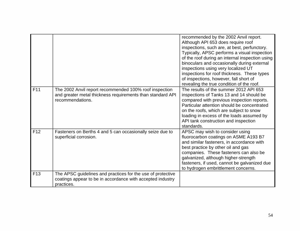
54
recommended by the 2002 Anvil report. Although API 653 does require roof inspections, such are, at best, perfunctory. Typically, APSC performs a visual inspection of the roof during an internal inspection using binoculars and occasionally during external inspections using very localized UT inspections for roof thickness. These types of inspections, however, fall short of revealing the true condition of the roof.
F11 The 2002 Anvil report recommended 100% roof inspection and greater metal thickness requirements than standard API recommendations.
The results of the summer 2012 API 653 inspections of Tanks 13 and 14 should be compared with previous inspection reports. Particular attention should be concentrated on the roofs, which are subject to snow loading in excess of the loads assumed by API tank construction and inspection standards.
F12 Fasteners on Berths 4 and 5 can occasionally seize due to superficial corrosion.
APSC may wish to consider using fluorocarbon coatings on ASME A193 B7 and similar fasteners, in accordance with best practice by other oil and gas companies. These fasteners can also be galvanized, although higher-strength fasteners, if used, cannot be galvanized due to hydrogen embrittlement concerns.
F13 The APSC guidelines and practices for the use of protective coatings appear to be in accordance with accepted industry practices.
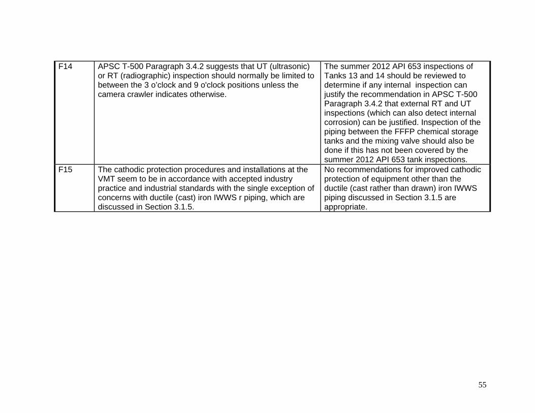
55
F14 APSC T-500 Paragraph 3.4.2 suggests that UT (ultrasonic) or RT (radiographic) inspection should normally be limited to between the 3 o’clock and 9 o'clock positions unless the camera crawler indicates otherwise.
The summer 2012 API 653 inspections of Tanks 13 and 14 should be reviewed to determine if any internal inspection can justify the recommendation in APSC T-500 Paragraph 3.4.2 that external RT and UT inspections (which can also detect internal corrosion) can be justified. Inspection of the piping between the FFFP chemical storage tanks and the mixing valve should also be done if this has not been covered by the summer 2012 API 653 tank inspections.
F15 The cathodic protection procedures and installations at the VMT seem to be in accordance with accepted industry practice and industrial standards with the single exception of concerns with ductile (cast) iron IWWS r piping, which are discussed in Section 3.1.5.
No recommendations for improved cathodic protection of equipment other than the ductile (cast rather than drawn) iron IWWS piping discussed in Section 3.1.5 are appropriate.

56
5.0 References 1. APSC MP-166-3.03, Facility Corrosion Monitoring, March 26, 2012. 2 Alaska Department of Environmental Control (DEC), 18 AAC 75, Oil and Other Hazardous Substances Pollution Control, April 8, 2012 3. NACE SP0198-2010, Control of Corrosion Under Thermal Insulation and Fireproofing Materials—A Systems Approach 4. CFR 195.583, What must I do to monitor atmospheric corrosion control?, http://ecfr.gpoaccess.gov/cgi/t/text/text- idx?c=ecfr&tpl=/ecfrbrowse/Title49/49cfr195_main_02.tpl , accessed August 28, 2012 5. Coffman Engineers, Inc., Valdez Marine Terminal Non-Tank Corrosion Abatement Study, submitted to PWSRCAC, February 28, 2005 6. T. Balowski, P. Ceder-Reinke, and C. Wang, Trans Alaska Pipeline System (TAPS) 2011 Annual Report, Pipeline and Valdez Marine Terminal Facilities Corrosion Monitoring,
7. Appendix C to CFR 195—Guidance for Implementation of an Integrity Management Program
8. R. Heidersbach, Metallurgy and Corrosion Control in Oil and Gas Production, John Wiley & Sons, Hoboken, NJ, 2011 9. ANSI/NACE SP0502-2010, Pipeline External Corrosion Direct Assessment Methodology 10. APSC MP-166.3.02, Internal Corrosion Investigation and Monitoring Program. 11. S. Harvey, Valdez Marine Terminal Oil Discharge Prevention and Contingency Plan (CP-35-2) Part 2, Oil Spill Prevention Review, December 16, 2011. 12. C. Palmer and R. King, 2006, Subsea Pipeline Engineering, PennWell, Tulsa, OK. 13. B. Hedges, H. J. Chen, T. H. Bieri, and K. Sprague, "A review of monitoring and inspection techniques for CO2 and H2S corrosion in oil and gas production facilities: location, location, location," NACE 06120
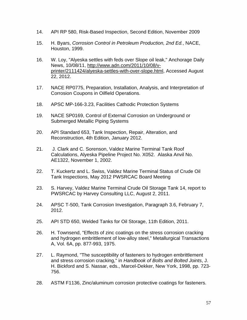
57
14. API RP 580, Risk-Based Inspection, Second Edition, November 2009 15. H. Byars, Corrosion Control in Petroleum Production, 2nd Ed., NACE, Houston, 1999. 16. W. Loy, "Alyeska settles with feds over Slope oil leak," Anchorage Daily News, 10/08/11, http://www.adn.com/2011/10/08/v- printer/2111424/alyeska-settles-with-over-slope.html, Accessed August 22, 2012. 17. NACE RP0775, Preparation, Installation, Analysis, and Interpretation of Corrosion Coupons in Oilfield Operations. 18. APSC MP-166-3.23, Facilities Cathodic Protection Systems 19. NACE SP0169, Control of External Corrosion on Underground or Submerged Metallic Piping Systems 20. API Standard 653, Tank Inspection, Repair, Alteration, and Reconstruction, 4th Edition, January 2012. 21. J. Clark and C. Sorenson, Valdez Marine Terminal Tank Roof Calculations, Alyeska Pipeline Project No. X052. Alaska Anvil No. AE1322, November 1, 2002. 22. T. Kuckertz and L. Swiss, Valdez Marine Terminal Status of Crude Oil Tank Inspections, May 2012 PWSRCAC Board Meeting 23. S. Harvey, Valdez Marine Terminal Crude Oil Storage Tank 14, report to PWSRCAC by Harvey Consulting LLC, August 2, 2011. 24. APSC T-500, Tank Corrosion Investigation, Paragraph 3.6, February 7, 2012. 25. API STD 650, Welded Tanks for Oil Storage, 11th Edition, 2011. 26. H. Townsend, "Effects of zinc coatings on the stress corrosion cracking and hydrogen embrittlement of low-alloy steel," Metallurgical Transactions A, Vol. 6A, pp. 877-993, 1975. 27. L. Raymond, "The susceptibility of fasteners to hydrogen embrittlement and stress corrosion cracking," in Handbook of Bolts and Bolted Joints, J. H. Bickford and S. Nassar, eds., Marcel-Dekker, New York, 1998, pp. 723- 756. 28. ASTM F1136, Zinc/aluminum corrosion protective coatings for fasteners.