Corrosion control
347
PEABODY’S CONTROL OF PIPELINE CORROSION SECOND EDITION A.W. PEABODY Edited by RONALD L. BIANCHETTI NACE International The Corrosion Society 1440 South Creek Drive Houston, Texas 77084
-
Upload
hitesh-mahajan -
Category
Technology
-
view
5.959 -
download
18
Transcript of Corrosion control

P1: FCE/FEP P2: FCECE003-FM CE003-Peabody November 16, 2000 13:35 Char Count= 0
PEABODY’SCONTROL OF PIPELINE CORROSIONSECOND EDITION
A.W. PEABODY
Edited byRONALD L. BIANCHETTI
NACE InternationalThe Corrosion Society1440 South Creek DriveHouston, Texas 77084
i

P1: FCE/FEP P2: FCECE003-FM CE003-Peabody November 16, 2000 13:35 Char Count= 0
NACE InternationalThe Corrosion Society
C© 1967, 2001 by NACE International
Second Edition 2001. All rights reserved.
Library of Congress Catalog Number 99-80032
ISBN 1-57590-092-0
Printed in the United States of America. All rights reserved. This book, or parts thereof,may not be reproduced in any form without permission of the copyright owners.
Neither NACE International, its officers, directors, or members thereof accept any re-sponsibility for the use of the methods and materials discussed herein. The informationis advisory only and the use of the materials and methods is solely at the risk of the user.
Cover illustration by Mark Lewis, courtesy of the East Bay Municipal Utility District.
NACE Press:Director of Publications: Jeff Littleton
Manager of NACE Press: Neil Vaughan
NACE International1440 South Creek DriveHouston, Texas 77084http://www.nace.org
ii

P1: FCE/FEP P2: FCECE003-FM CE003-Peabody November 16, 2000 13:35 Char Count= 0
Table of Contents
Preface vAbout the Author viiContributors ix
Chapter 1 Introduction to CorrosionJohn A. Beavers 1
Chapter 2 Pipeline CoatingsRichard N. Sloan 7
Chapter 3 Cathodic Protection—How It WorksJohn A. Beavers 21
Chapter 4 Criteria for Cathodic ProtectionJohn A. Beavers and Kevin C. Garrity 49
Chapter 5 Survey Methods and Evaluation TechniquesRonald L. Bianchetti 65
Chapter 6 InstrumentationMark Lewis 101
Chapter 7 Ground Bed DesignRonald L. Bianchetti 131
Chapter 8 Impressed Current Cathodic ProtectionRonald L. Bianchetti 157
iii

P1: FCE/FEP P2: FCECE003-FM CE003-Peabody November 16, 2000 13:35 Char Count= 0
iv Table of Contents
Chapter 9 Cathodic Protection with Galvanic AnodesRonald L. Bianchetti 177
Chapter 10 Cathodic Protection with Other Power SourcesJohn A. Beavers 201
Chapter 11 Stray Current CorrosionMichael J. Szeliga 211
Chapter 12 Construction PracticesRonald L. Bianchetti 237
Chapter 13 Maintenance ProceduresRonald L. Bianchetti 261
Chapter 14 Microbiologically Influenced CorrosionBrenda J. Little and Patricia Wagner 273
Chapter 15 EconomicsRonald L. Bianchetti 285
Chapter 16 Fundamentals of CorrosionJohn A. Beavers 297
Appendix A NACE Glossary of Corrosion-Related Terms 319
Appendix B Additional Important Information on Underground Corrosion Control 339
Index 341
P1: FCE/FEP P2: FCECE003-FM CE003-Peabody November 16, 2000 13:35 Char Count= 0
Preface
This book was originally published in 1967 by Sam Peabody and is the most quoted andused document in the corrosion industry for pipeline corrosion control and testing. Whenthe original book was published, specific criteria for cathodic protection for undergroundpipelines were still under evaluation and consideration. Not until 1969 was the firstdocumented standard approved by NACE International on criteria RP0169. The depthand vision that Peabody incorporated in the first version of the book has stood the testof time.
This revised version of the 1967 book is not an attempt to make radical changes to theoriginal document. Much of the original text and concepts remain intact. We attempted,however, to incorporate original traditional elements of the book with updates andexpanded discussions on equipment, testing techniques and criteria, coatings, surveymethods, and data analysis.
An integral part of this revision is a CD-ROM that contains formulas of key designcalculations, case examples of corrosion control designs which provide a set-by-stepoverview of how to design various components of cathodic protection systems, and anelectronic copy of the revised book edition.
As described in the Preface of the original 1967 edition, every attempt has been madeto check the accuracy of all statements and other data. However, it is unreasonableto assume that everything in this book is accurate and exact. Any suggestions will beconsidered when future editions of this book are prepared.
v

P1: FCE/FEP P2: FCECE003-FM CE003-Peabody November 16, 2000 13:35 Char Count= 0
About the Author
1915–1998
This updated version of NACE International’s book titled Control of Pipeline Corrosion isdedicated to the memory of its original author, A.W. (Sam) Peabody. Since its publicationin 1967, the book has been translated into at least seven different languages and isconsidered by most as the definitive work on pipeline corrosion.
Sam received his bachelor’s degree from the University of Maine and pursued grad-uate studies at the Brooklyn Polytechnic Institute in New York. He worked for EbascoServices Inc. (no longer in existence) for over 40 years until his retirement in 1980 asDirector of Corrosion Engineering. He was an active member of NACE since 1947. Hisaccomplishments, awards, and recognitions are too many to list here. His biggest legacy,especially to those of us who had the privilege of working for and with him, is that hewas the perfect example of “a gentleman and a scholar.” He was an excellent teacherwho always emphasized professional integrity, a quality he instilled in so many.
vii

P1: FCE/FEP P2: FCECE003-FM CE003-Peabody November 29, 2000 10:8 Char Count= 0
Contributors
John A. Beavers
John A. Beavers is Vice President of Research at CC Technologies, a corrosion engineeringand research company. He received B.S. and Ph.D. degrees in metallurgical engineering fromthe University of Illinois at Urbana-Champaign in 1973 and 1977, respectively. Dr. Beavershas directed and contributed to numerous research programs on corrosion performance ofstructural materials. These programs included failure analyses, critical literature reviews, andlaboratory and field evaluations of metallic and non-metallic material. Dr. Beavers has utilizedstate-of-the-art electrochemical, surface analytical, and mechanical techniques for the evalua-tion of materials performance. A major emphasis of his research has been the mechanistic andpractical aspects of corrosion and stress corrosion cracking (SCC) on underground pipelines.Dr. Beavers worked at Battelle Memorial Institute from 1977 to 1987, where he was a SeniorResearch Leader in the Corrosion Section. He joined CC Technologies in 1987.
Dr. Beavers has authored over 80 papers in the field of corrosion and has received twoU.S. Patents. An active member of NACE, he was Chairman of the Research in ProgressSymposium in 1994 and of the Publications Committee in 1991 and 1992.
Editor’s Note: Sincere appreciation to John Beavers for investing a lot of time on a detailed andproductive review of the final draft on the eve before printing.
Ronald L. Bianchetti
Ronald L. Bianchetti is currently a Senior Engineer at East Bay Municipal Utility District(EBMUD) in Oakland, California. He received a B.S. in engineering in 1975 from theUniversity of California, Davis and an MBA in 1981 from St. Mary’s College of California.He is a Registered Professional Engineer and has over 25 years of experience. Prior to holdinghis current position, Mr. Bianchetti worked in the private sector as a consultant in the cor-rosion industry from 1975 to 1992. His work includes planning, designing, testing, and theconstruction management of cathodic protection systems for underground pipelines, tanks,refineries, power plants, and marine structures. He has served in NACE International as Past
ix

P1: FCE/FEP P2: FCECE003-FM CE003-Peabody November 29, 2000 10:8 Char Count= 0
x Contributors
Chairman of the Publications Committee, ad-hoc member to the Board of Directors, PastWestern Region Chairman and Past Section Chair of the San Francisco Section.
Mr. Bianchetti has published over 30 papers in the field of corrosion and has given hun-dreds of presentations on corrosion and corrosion control.
Kevin C. Garrity, P.E.
Kevin C. Garrity, P.E., is currently Vice President of Engineering at CC Technologies, a cor-rosion engineering and research company. He received a B.S. in electrical engineering in1974 from the Polytechnic Institute of Brooklyn. He is a NACE Certified Cathodic ProtectionSpecialist and a Registered Professional Engineer in seven states. Mr. Garrity has 26 yearsof experience in the design, installation, monitoring, and assessment of cathodic protectionsystems for buried pipelines, underground storage tanks, concrete structures, and marinestructures. Mr. Garrity worked at Ebasco Services from 1974 to 1982, where he was a SeniorCorrosion Engineer, and at Harco Corporation from 1982 to 1989, where he was Vice Presidentof Engineering. He joined CC Technologies in 1989.
In 1996, Mr. Garrity received the Colonel George W. Cox Award for outstanding contribu-tions to the field of underground corrosion control. He has published more than 20 papers inthe field of corrosion control. Mr. Garrity delivered the plenary lecture at Corrosion’98.
Mark Lewis
Mark Lewis is Assistant Corrosion Engineer at the East Bay Municipal Utility District(EBMUD) in Oakland, California. He is a graduate of Kent State University and attendedBethany College in West Virginia. He has worked in the cathodic protection and corrosionengineering field since 1980, both within the United States and internationally. He is a PastChairman of the San Francisco Bay Area Section of NACE International.
He is the author of several technical and historical articles on cathodic protection and hasmade numerous presentations on the subject. Mr. Lewis has a patent pending for a distributionsystem rectifier design.
Brenda J. Little
Brenda J. Little, Senior Scientist for Marine Molecular Processes at the Naval Research Labora-tory, has a Ph.D. in chemistry from Tulane University and a B.S. in biology and chemistry fromBaylor University. She is a member of the American Chemical Society and the National As-sociation of Corrosion Engineers (NACE International). She is a NACE International Fellowand the recipient of a 1999 NACE International Technical Achievement Award.
Dr. Little serves on the editorial board for Biofouling and is the author of one book, 20book chapters, and over 80 peer-reviewed journal articles.
P1: FCE/FEP P2: FCECE003-FM CE003-Peabody November 29, 2000 10:8 Char Count= 0
Contributors xi
Steve McKim
Since 1989, Steve McKim has been Vice President of American Construction & Supply, Inc.Based in Mill Valley, California, his company specializes in cathodic protection constructionservices. Mr. McKim previously worked with Harco Corporation and Chevron USA. He hasbeen in the corrosion industry since he graduated from the University of Illinois with a B.S. inmechanical engineering in 1983. He is a Past Chairman of the NACE San Francisco Bay AreaSection.
Richard N. Sloan
The late Richard Sloan, was an authority in the field of pipeline coatings. He worked for over45 years with a company that was first known as HC Price. (The company changed its nameseveral times: HC Price, Ameron Price, Bredero Price, and Energy Coatings.) He attendedDrexel University and graduated with a bachelor’s degree in Industrial Administration.
During his professional career, Richard Sloan taught various short courses in pipelinecoatings, and was a speaker at numerous seminars on the subject. The late Mr. Sloan was anactive and long-standing member of NACE, AWWA, and Western Pipeliners.
Michael J. Szeliga
Michael J. Szeliga, P.E., is the Chief Engineer for Russell Corrosion Consultants, Inc. He hasmore than 23 years of experience in corrosion control engineering. Much of his work hasinvolved the analysis and control of stray current from DC-powered transit systems andfrom impressed current cathodic protection systems. A Licensed Professional Engineer inseveral states and certified by NACE International as a Corrosion Specialist and a CathodicProtection Specialist, Mr. Szeliga has been and is the principal corrosion consultant for thedesign, construction, and maintenance of many light and heavy rail transit systems. He ispresently chairman of the NACE (05)024X Committee on Interference Problems Associatedwith Rail Transit. Mr. Szeliga is also chairman of the ASTM subcommittee on stray current.
He has edited a book for NACE International titled Stray Current Corrosion and has pub-lished several articles on the subject.
Patricia Wagner
Patricia Wagner retired from the Naval Research Laboratory in 1998 after 14 years of extensiveexperience in microbiologically influenced corrosion. She is the coauthor of one book and theauthor of numerous articles on corrosion.

P1: GKW/SPH P2: GKW/UKS P3: GKW/UKS QC: GKW/UKS T1: GKWCE003-01 CE003-Peabody November 15, 2000 10:33 Char Count= 0
Chapter1Introduction to Corrosion
John A. Beavers
WHAT IS CORROSION?
One general definition of corrosion is the degradation of a material through environ-mental interaction. This definition encompasses all materials, both naturally occurringand man-made and includes plastics, ceramics, and metals. This book focuses on thecorrosion of metals, with emphasis on corrosion of carbon and low-alloy steels usedin underground pipelines. This definition of corrosion begs the question; why do met-als corrode? The answer lies in the field of thermodynamics, which tells whether aprocess such as corrosion will occur. A second logical question is what is the rateof corrosion or how long will a pipeline last? Corrosion kinetics can help provide ananswer to this question. Both topics are discussed in greater detail in Chapter 16. Chap-ter 1 contains an introduction to the subject of underground corrosion. A glossary ofterms is included in Appendix A of this book to help with the sometimes confusingterminology.
A significant amount of energy is put into a metal when it is extracted from itsores, placing it in a high-energy state. These ores are typically oxides of the metal suchas hematite (Fe2O3) for steel or bauxite (Al2O3·H2O) for aluminum. One principle ofthermodynamics is that a material always seeks the lowest energy state. In other words,most metals are thermodynamically unstable and will tend to seek a lower energy state,which is an oxide or some other compound. The process by which metals convert to thelower-energy oxides is called corrosion.
Corrosion of most common engineering materials at near-ambient temperatures oc-curs in aqueous (water-containing) environments and is electrochemical in nature. Theaqueous environment is also referred to as the electrolyte and, in the case of under-ground corrosion, is moist soil. The corrosion process involves the removal of elec-trons (oxidation) of the metal [Equation (1)] and the consumption of those electrons bysome other reduction reaction, such as oxygen or water reduction [Equations (2) and (3),
1

P1: GKW/SPH P2: GKW/UKS P3: GKW/UKS QC: GKW/UKS T1: GKWCE003-01 CE003-Peabody November 15, 2000 10:33 Char Count= 0
2 Introduction to Corrosion
respectively]:
Fe→ Fe++ + 2e− (1)
O2 + 2H2O+ 4e− → 4OH− (2)
2H2O+ 2e− → H2 + 2OH− (3)
The oxidation reaction is commonly called the anodic reaction and the reductionreaction is called the cathodic reaction. Both electrochemical reactions are necessary forcorrosion to occur. The oxidation reaction causes the actual metal loss but the reductionreaction must be present to consume the electrons liberated by the oxidation reaction,maintaining charge neutrality. Otherwise, a large negative charge would rapidly developbetween the metal and the electrolyte and the corrosion process would cease.
The oxidation and reduction reactions are sometimes referred to as half-cell reactionsand can occur locally (at the same site on the metal) or can be physically separated.When the electrochemical reactions are physically separated, the process is referred toas a differential corrosion cell. A schematic of a differential corrosion cell is given inFigure 1.1. The site where the metal is being oxidized is referred to as the anode oranodic site. At this site, direct electric current (defined as a positive flow of charge) flowsfrom the metal surface into the electrolyte as the metal ions leave the surface. This currentflows in the electrolyte to the site where oxygen, water, or some other species is beingreduced. This site is referred to as the cathode or cathodic site. There are four necessarycomponents of a differential corrosion cell.
1. There must be an anode2. There must be a cathode
Figure 1.1 Schematic showing a differential corrosion cell.

P1: GKW/SPH P2: GKW/UKS P3: GKW/UKS QC: GKW/UKS T1: GKWCE003-01 CE003-Peabody November 15, 2000 10:33 Char Count= 0
How Do We Detect Corrosion? 3
3. There must be a metallic path electrically connecting the anode and cathode. (Nor-mally, this will be the pipeline itself.)
4. The anode and cathode must be immersed in an electrically conductive electrolyte(normally, moist soil).
Underground corrosion of pipelines and other structures is often the result of differ-ential corrosion cells of which a variety of different types exist. These include differentialaeration cells, where different parts of a pipe are exposed to different oxygen concen-trations in the soil, and cells created by differences in the nature of the pipe surface orthe soil chemistry. Galvanic corrosion is a form of differential cell corrosion in whichtwo different metals are electrically coupled and exposed in a corrosive environment.Further discussion of these differential corrosion cells is given below and in Chapter 16.
HOW DO WE DETECT CORROSION?
The electrochemical nature of the corrosion process provides opportunities to detectand mitigate corrosion of underground structures. We can monitor the voltages and thecurrents associated with the corrosion process.
When a piece of metal is placed in an electrolyte, such as soil, a voltage will developacross the metal–electrolyte interface because of the electrochemical nature of the cor-rosion process. We cannot measure this voltage directly but, using a voltmeter, we canmeasure a voltage between two different metals that are placed in the soil. We also canmeasure the voltage difference between a metal and a reference electrode, commonlycalled a half-cell electrode. This voltage is referred to as a corrosion potential, an opencircuit potential, or a native potential for that metal in the environment in which the mea-surement is being obtained. For soil environments, the most common reference electrodeused is the copper–copper sulfate reference electrode (CSE).
Potential measurements can be used to estimate the relative resistance of differentmetals to corrosion in a given environment. Noble metals, such as gold and platinum,have more positive potentials and are more resistant to corrosion than are the morecommon engineering metals such as steel and aluminum. A galvanic series is a list ofmetals and alloys arranged according to their relative corrosion potentials in a givenenvironment. Table 1.1 shows a galvanic series for metals and other materials in neutralsoils and water, indicating that carbon has the most positive potential of the materialslisted and magnesium has the most negative potential. The potentials measured for thedifferent metals in a galvanic series vary somewhat, depending on the nature of theenvironment, but the relative position of the metals is similar for natural environmentssuch as soil and seawater.
Another use for corrosion potential measurements is to establish whether galvaniccorrosion is likely to occur. When two metals are electrically coupled in an environ-ment, the more negative (active) member of the couple will become the anode in the

P1: GKW/SPH P2: GKW/UKS P3: GKW/UKS QC: GKW/UKS T1: GKWCE003-01 CE003-Peabody November 15, 2000 10:33 Char Count= 0
4 Introduction to Corrosion
Table 1.1 Practical Galvanic Series for Materials in Neutral Soilsand Water
Material Potential Volts (CSE)a
Carbon, Graphite, Coke +0.3Platinum 0 to −0.1Mill Scale on Steel −0.2High Silicon Cast Iron −0.2Copper, Brass, Bronze −0.2Mild Steel in Concrete −0.2Lead −0.5Cast Iron (Not Graphitized) −0.5Mild Steel (Rusted) −0.2 to −0.5Mild Steel (Clean and Shiny) −0.5 to −0.8Commercially Pure Aluminum −0.8Aluminum Alloy (5% Zinc) −1.05Zinc −1.1Magnesium Alloy (6% Al, 3% Zn, 0.15% Mn) −1.6Commercially Pure Magnesium −1.75
aTypical potential normally observed in neutral soils and water, mea-sured with respect to copper sulfate reference electrode.
differential corrosion cell, and the more positive (noble) member of the couple will be-come the cathode in the cell. In general, the severity of the galvanic couple increases asthe difference in potential between the two members of the couple increases, althoughthis is not always the case. The galvanic series shown in Table 1.1 indicates that, wherecopper is electrically coupled to mild steel in soil, the copper will become the cathode andthe steel will become the anode, accelerating corrosion of the steel. A further discussionof galvanic corrosion is given in Chapter 16.
Table 1.1 also shows that the potential of mild steel can differ depending on whetherthe surface is clean or covered with mill scale. The potential of steel also is a function ofsoil properties, including pH, ion concentration, oxygen, and moisture content. The po-tential differences that develop on underground pipelines and other structures as a resultof these factors can result in severe corrosion. Further discussions of these differentialcorrosion cells are given in Chapter 16.
Potential measurements are commonly used on underground pipelines to detect thepresence of these types of differential corrosion cells. An electrical connection is made tothe pipe, and the potential of the pipe is measured with respect to a reference electrodeplaced over the pipe. This process is shown schematically in Figure 1.2. Normally, thereference electrode is connected to the negative lead of a digital voltmeter to obtain anegative reading. As shown in Table 1.1, most potentials in soils are negative. With thistype of measurement, the most negative regions of the structure are the anodes and areundergoing accelerated corrosion due to the differential corrosion cells.

P1: GKW/SPH P2: GKW/UKS P3: GKW/UKS QC: GKW/UKS T1: GKWCE003-01 CE003-Peabody November 15, 2000 10:33 Char Count= 0
How Do We Mitigate Corrosion? 5
Figure 1.2 Schematic showing a pipe-to-soil potential measurement.
Current measurements also can be used to detect differential corrosion cells if theanodes and cathodes are large. These large cells create long-line currents that can bedetected by measurements made over the pipe or other underground structure. ThroughOhm’s law (V = IR, where V is the voltage, I is the current, and R is the resistance)we know that current flow in the soil will create a voltage gradient. This gradient canbe detected by placing identical reference electrodes over the pipe and measuring thevoltage difference. The voltage measurements can be used to indicate the direction ofthe differential cell current. The anodic and cathodic sites on the pipeline can be locatedby performing a series of cell-to-cell potential measurements taken along the pipeline.Another possible source of current flow in the ground is stray currents. These issues arediscussed further in Chapter 5.
HOW DO WE MITIGATE CORROSION?
The principal methods for mitigating corrosion on underground pipelines are coatingsand cathodic protection (CP). Although each will be treated in greater detail in thefollowing chapters, these two methods are briefly described here.

P1: GKW/SPH P2: GKW/UKS P3: GKW/UKS QC: GKW/UKS T1: GKWCE003-01 CE003-Peabody November 15, 2000 10:33 Char Count= 0
6 Introduction to Corrosion
Coatings normally are intended to form a continuous film of an electrically insulatingmaterial over the metallic surface to be protected. The function of such a coating is toisolate the metal from direct contact with the surrounding electrolyte (preventing theelectrolyte from contacting the metal) and to interpose such a high electrical resistancethat the electrochemical reactions cannot readily occur. In reality, all coatings, regardlessof overall quality, contain holes, referred to as holidays, that are formed during appli-cation, or during transport or installation of mill-coated pipe. Holidays in coatings alsodevelop in service as a result of degradation of the coating, soil stresses, or movement ofthe pipe in the ground. Degradation of the coating in service also can lead to disbondingfrom the pipe surface, further exposing metal to the underground environment. A highcorrosion rate at a holiday or within a disbonded region can result in a leak or rupture,even where the coating effectively protects a high percentage of the pipe surface. Thus,coatings are rarely used on underground pipelines in the absence of CP. The primaryfunction of a coating on a cathodically protected pipe is to reduce the surface area ofexposed metal on the pipeline, thereby reducing the current necessary to cathodicallyprotect the metal. Further discussion of coatings is given in Chapter 2.
One definition of CP is a technique to reduce the corrosion rate of a metal surfaceby making it the cathode of an electrochemical cell. This is accomplished by shifting thepotential of the metal in the negative direction by the use of an external power source(referred to as impressed current CP) or by utilizing a sacrificial anode. In the case of animpressed current system, a current is impressed on the structure by means of a powersupply, referred to as a rectifier, and an anode buried in the ground. In the case of asacrificial anode system, the galvanic relationship between a sacrificial anode material,such as zinc or magnesium, and the pipe steel is used to supply the required CP current.Further discussions of CP are given in Chapters 3 and 16.

P1: FPVCE003-02 CE003-Peabody November 3, 2000 11:44 Char Count= 0
Chapter2Pipeline Coatings
Richard N. Sloan
When the first edition of Control of Pipeline Corrosion by A.W. Peabody was published in1967, there were few governmental regulations to contend with. Today the Department ofTransportation–Office of Pipeline Safety (DOT/OPS), Occupational Safety and HealthAdministration (OSHA), and the Department of Environmental Resources (DER) areamong the many regulatory agencies influencing or controlling the pipeline industry.Governmental regulations, along with the development, introduction, and acceptance ofnew pipeline coatings, have made major changes and will continue to affect the selectionand use of pipeline coatings in the future.
Economics, while still a factor, is being replaced by safety and environmental con-cerns to obtain the best available pipe-coating systems. This trend was first apparent inEurope where permanence, instead of cost, led to the use of multi-layer systems thathave proven to be most effective and more economical over the life of the pipeline. Intoday’s regulated environment, all new hazardous pipelines (carrying oil, gas, or otherpotentially dangerous substances) are required by federal regulation to use an effectivecoating and cathodic protection (CP).
EFFECTIVENESS OF COATINGS AS A MEANS OF CORROSION CONTROL
First attempts to control pipeline corrosion relied on the use of coating materials and thereasoning that if the pipeline metal could be isolated from contact with the surroundingearth, no corrosion could occur. This concept is entirely reasonable and logical. Further-more, a coating would be completely effective as a means of stopping corrosion if thecoating material:
• Is an effective electrical insulator,
7

P1: FPVCE003-02 CE003-Peabody November 3, 2000 11:44 Char Count= 0
8 Pipeline Coatings
• Can be applied with no breaks whatsoever and will remain so during the backfillingprocess, and
• Constitutes an initially perfect film that will remain so with time.
While this is possible with some of the advanced multi-layer systems, it may not bepractical from an initial cost analysis.
Although coatings by themselves may not be the one perfect answer to corrosioncontrol, they are extremely effective when properly used. Most operators plan coatingsand cathodic protection (CP) for all their pipelines as a matter of course. A properlyselected and applied coating will provide all the protection necessary on most of thepipeline surface to which it is applied. On a typical well-coated pipeline this should bebetter than 99% and, along with the CP, should give total protection.
It is not the intent of the chapter to make specific recommendations for coating ma-terials to be used. However, the capabilities and limitations of various pipeline coatingmaterials will be discussed as well as desirable characteristics and how to get the mostof any material used. Types of coatings now used on pipeline systems will be describedbriefly.
NACE Standard RP0169-96 Section 5: Coatings, is a comprehensive guide to pipecoatings, and is required reading for a better understanding of their importance. ThisStandard lists the following desirable characteristics of coatings:
1. Effective electrical insulator. Because soil corrosion is an electrochemical process,a pipe coating has to stop the current flow by isolating the pipe from its installedenvironment/electrolyte. To assure a high electrical resistance, the coating shouldhave a high dielectric strength.
2. Effective moisture barrier. Contrary to the theory that water absorption is goodbecause it increases the effectiveness of CP, water transfer through the coating maycause blistering and will contribute to corrosion by prohibiting isolation.
3. Applicability. Application of the coating to the pipe must be possible by a methodthat will not adversely affect the properties of the pipe and with a minimum ofdefects.
4. Ability to resist development of holidays with time. After the coating is buried, twoareas that may destroy or degrade coatings are soil stress and soil contaminants. Soilstress, brought about in certain soils that are alternately wet and dry, creates forcesthat may split or cause thin areas. To minimize this problem, one must evaluate thecoating’s abrasion resistance, tensile strength, adhesion, and cohesion. The coating’sresistance to chemicals, hydrocarbons, and acidic or alkaline conditions should beknown for evaluating their performance in contaminated soils.
5. Good adhesion to pipe surface. The pipe coating requires sufficient adhesion toprevent water ingress or migration between the coating and the pipe, along withcohesion to resist handling and soil stress. Soil stress is the main cause of pipe coat-ing failure. “Soil stress effects can be seen on flexible PE coatings with elastomericadhesives as a characteristic wrinkling. However, other types of coatings can failby blistering fusion-bonded epoxy (FBE) or fatigue cracking coal tar enamel (CTE)

P1: FPVCE003-02 CE003-Peabody November 3, 2000 11:44 Char Count= 0
Effectiveness of Coatings as a Means of Corrosion Control 9
that are exacerbated by soil movement. . . . resistance to shear must be combinedwith a measurement of the resistance of the backing material (or outer jacket) todeformation and tensile force. The two properties combine to determine the abilityof a pipeline coating to resist damage to soil movement.” Soil stress resistance ismeasured by shear resistance, not by peel strength.
6. Ability to withstand normal handling, storage (UV degradation), and installation.The ability of a coating to withstand damage is a function of its impact, abrasion,and flexibility properties. Pipe coatings are subject to numerous handlings betweenapplication and backfill. Their ability to resist these forces vary considerably, so thosefactors need to be evaluated to know if any special precautionary measure should beused. Ultraviolet rays can be very destructive to pipe coatings. Storage life may varyfrom 6 months to 5 years so resistance to ultraviolet is a very important consideration.
7. Ability to maintain substantially constant electrical resistivity with time. The ef-fective electrical resistance of a coating per average square foot depends on thefollowing.
• Resistivity of the coating material• Coating thickness• Resistance to moisture absorption• Resistance to water vapor transfer• Frequency and size of holidays• Resistivity of the electrolyte• Bond or adhesion of coating
If the effective resistance is unstable, the CP required may double every few years. Itis easy to obtain misleading higher resistance measurements if the soil has not settledaround the pipeline and if the moisture has permeated to any holidays in the coating.Experience is necessary to evaluate the validity of these resistance measurements andto use them for designing the CP system.
8. Resistance to disbonding. Because most pipelines are cathodically protected, thecoating must be compatible with CP. The amount of CP required is directly propor-tional to the quality and integrity of the coating. The negative aspects of CP are that itmay drive water through the coating and that the interface bond surrounding a hol-iday may have a tendency to disbond. No coating is completely resistant to damageby CP. When large amounts of current are required, stray current and interferenceproblems may arise. This emphasizes the importance of proper coating selection,application, and installation.
9. Ease of repair. Because the perfect pipe coating does not exist, we can expect to makesome field repairs as well as field-coating of the weld area. Check for compatibilityand follow the manufacturer’s recommendations. A field repair is never as good asthe original coating. Tight inspection should be maintained.
10. Nontoxic interaction with the environment. Some coating materials have been mod-ified, restricted, or banned because of environmental and health standards. Asbestosfelts and primers with certain solvents have required substitution of glass rein-forcements and modification of solvents; changes in fusion-bonded epoxy powders
P1: FPVCE003-02 CE003-Peabody November 3, 2000 11:44 Char Count= 0
10 Pipeline Coatings
to eliminate carcinogenic agents have also been necessitated by health and envi-ronmental concerns. This has been a major influence of change on today’s pipecoatings.
In addition to the above characteristics, the following typical factors should be con-sidered when selecting a pipe coating.
• Type of environment• Accessibility of pipeline• Operating temperature of pipeline• Ambient temperatures during application, storage, shipping, construction, and in-
stallation• Geographical and physical location• Type of coating on existing pipeline• Handling and storage• Installation methods• Costs• Pipe surface preparation requirements
Good practice in modern pipeline corrosion control work comprises the use of goodcoatings in combination with CP as the main lines of defense. Supplementary tactics,such as the use of insulated couplings and local environmental control may be used toreinforce these basic control methods.
In selecting a coating system for a given pipeline project, one of the most importantcharacteristics to design for is stability. By this we mean a coating combination that willhave a high electrical resistance after the pipeline has been installed and the backfillstabilized and will lose the least electrical resistance over time.
Those characteristics are important in any event but particularly so where CP is usedto supplement the coating. When used with an unstable coating, a CP system that is fullyadequate during the early life of a pipeline may no longer provide full protection as thecoating deteriorates (as indicated by a reduction in the effective electrical resistance of thecoating), which will require additional current. This means that continued expenditureswill be necessary for additional CP installations. The overall economics of the coating-plus-CP concept are adversely affected by poor coating performance.
In a review of 50 years of literature on pipeline coatings, the following conceptsemerged:
• Selection of the best coating and proper application are very important.• CP must supplement the coating for 100% protection.• In-the-ground tests are more reliable than laboratory tests.• Results of adhesion tests do not correlate with those of cathodic disbondment tests.• Cathodic disbondment tests are the best tests to measure coating performance.• The current required for CP is the best measure of coating performance.

P1: FPVCE003-02 CE003-Peabody November 3, 2000 11:44 Char Count= 0
Specifications 11
• Optimum coating thickness is important.• Soil stress is one of the main problems.• Resistance to cathodic disbondment and soil stress are very important requirements
of a pipe coating. For a pipe coating to be effective, it should meet these criteria:adhesion, adequate thickness, low moisture absorption/transfer, chemical resistance(especially alkalis from CP), and flexibility.
• Selection of the best appropriate system is important, but proper application is themost important consideration.
A major cause of pipeline coating failure is improper application. A quality materialpoorly applied is of little value, and the quality of a pipe coating is only as good as thequality of application. To assist in the evaluation of an applicator, the following pointsshould be considered.
1. Experience. Research and trial and error have gone into the development of everycoating, with close cooperation between applicator, coating manufacturer, equipmentmanufacturer, and customer. The transition from laboratory to production line is usu-ally a costly experience, which should not be ignored.
2. Reputation. This is an asset earned by consistent performance. Not only good qualitywork but also solving problems and correcting mistakes help to develop a reputation.
3. Reliability. Many variables affect the application of coatings. A reliable work force,well-maintained equipment, and consistent quality performance are prerequisites foran applicator.
4. Conformance to the coating manufacturer’s specifications. The manufacturer’s es-tablished minimum specifications for application of materials should be met.
5. Modern automated equipment. Capital expenditure on automated application equip-ment is an important part of the success of plastic coatings. Elimination of human er-rors through automation and controls continues to be an important factor in improvedpipe coatings.
6. Quality control. Conformance to specifications has to be checked regularly. Knowl-edge of the applicator’s quality control procedures on materials, application, andfinished product is essential in the selection of an applicator.
SPECIFICATIONS
Pipeline coating should not be attempted without rigid specifications that precisely spellout every step of the coating procedure to be used. Such specifications are necessary toensure that the materials being used are applied in a manner that will permit develop-ment of the best coating of which those materials are capable.
Because many materials may be used, no specific example of coating specifica-tions will be attempted here. Specifications can be prepared in accordance with the
P1: FPVCE003-02 CE003-Peabody November 3, 2000 11:44 Char Count= 0
12 Pipeline Coatings
manufacturer’s recommendations with such modifications as may be dictated by con-ditions applicable to the particular project and requirements of the pipeline system inwhich the coated pipe is to be used.
Areas to be covered by specifications should include the following.
• Cleaning the pipe surface• Priming, if required• The coating materials to be used and (if more than one material) the order in which
they are to be applied• Total thickness with permissible tolerances• Specifications applicable to the particular materials to be used, such as application
temperature and thickness, tension (for tapes or wrappers), and other items of a similarnature
• Handling requirements for coating materials, such as storage provisions and mainte-nance of dry and clean conditions
• Inspection requirements• Procedure for repair of coating defects• Basis for rejection of unacceptable coating• Requirements for handling and transporting the coated pipe• Details of coating field joints when factory coated pipe is used• Backfilling requirements
INSPECTION PROCEDURES
Once the coating system and applicator are selected, an important part of a qualityinstallation is good inspection. Inspection should begin with the stockpile of bare pipethrough coating operations, load out, coated pipe stockpile, field inspection, joint coatingprocedure, and backfill of coated pipe. Knowledge of the coating system, plant facilities,quality control methods, shipping requirements, handling, joint coating, field conditions,field holiday detection, and repair are requirements for proper installation. Experienceand common sense in interpretation of specifications and analysis of test results willcontribute to obtaining the best possible coating results.
As a final backup to application supervision exercised by the coating inspector, usualpipelining practice includes a final test with a holiday detector (or “jeep”). This deviceimpresses an electrical voltage across the coating. An electrode is passed over the entirecoating surface and, as it passes over a coating defect, there is an electrical dischargebetween electrode and pipe. This discharge, or spark, actuates a signaling device, whichwarns the operator that a holiday has been detected. The operator marks the defect forthe repair crew and continues.
Refer to the proper NACE specification when examining for holidays: RP02-74 (latestrevision) for the thicker coatings, or RP04-95 (latest revision) for the thinner coatingsystems.

P1: FPVCE003-02 CE003-Peabody November 3, 2000 11:44 Char Count= 0
Inspection Procedures 13
Plant Holiday Inspection
Pipe coated at a coating plant normally is passed through a holiday detector beforeshipment. Both mill-coated pipe and that coated over the ditch should be subjected to afinal holiday test before being placed in the ditch.
The fewer the defects in a coating which is to be repaired, the better the quality of thecompleted coating. Nevertheless, if all holidays are picked up by a detector in properoperating conditions, and if they are repaired to conform to an effective procedure, thenthe quality of the coating as it enters the ditch will at least approach an optimum.
Field Holiday Inspection
Several types of holiday detectors are suitable for field use at the pipeline constructionsite. The most common ones are usually battery operated and equipped with some typeof pipe-encircling electrode. The electrode is arranged so that the ring may be pushed orrolled along the pipe by the operator, allowing the electrode to sweep all portions of thecoating surface.
The holiday detector should be operated in strict accordance with the manufacturer’sinstructions. The coating inspector should be sure the operator has been trained properlyand is using the equipment correctly. Some practical operating procedures that apply toany type of holiday locator include the following.
1. Use only adequately charged batteries in battery-operated models.2. Use detectors that are set to operate at a voltage suitable for the coating being applied.
Thick coatings require a high voltage to spark through at defects. On the other hand,too high a voltage may break down thin film coatings such as tapes or other thinplastic coatings.
3. Verify periodically that the detector is operating properly. This may be done bypurposely making a coating defect (such as a pinhole made with a knife) and pass-ing the detector over the hole. Failure to detect the hole properly indicates the needfor prompt corrective adjustment. During production work, verification should bemade at least twice a day and at such other times as the inspector may suspect poorperformance.
4. Keep the contact electrodes clean. A buildup of coating material on electrodes mayinterfere with efficient detection or even prevent it entirely. This possibility is greaterwith some materials than others. Where found to be a factor, keeping the electrodesclean of the insulating coating material must be insisted on.
5. Maintain a good ground. To be complete, the detector circuit must contact the earth,with a trailing ground wire for example. This trailing wire should be checked fordamage daily (or whenever faulty detector operation is suspected) and replaced orrepaired if faulty. When working on long sections of line, there usually will be sufficient
P1: FPVCE003-02 CE003-Peabody November 3, 2000 11:44 Char Count= 0
14 Pipeline Coatings
conductance between line and earth to permit adequate detector operation. On theother hand, a short length of well-coated pipe on dry skids may have to be groundedto the pipe to establish an adequate circuit.
TYPES OF PIPELINE COATINGS
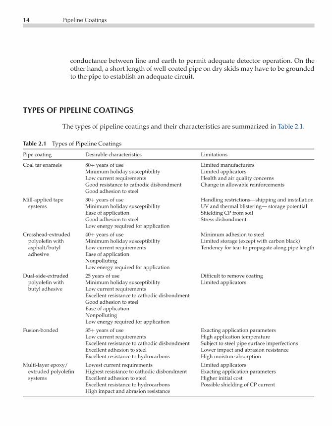
The types of pipeline coatings and their characteristics are summarized in Table 2.1.
Table 2.1 Types of Pipeline Coatings
Pipe coating Desirable characteristics Limitations
Coal tar enamels 80+ years of use Limited manufacturersMinimum holiday susceptibility Limited applicatorsLow current requirements Health and air quality concernsGood resistance to cathodic disbondment Change in allowable reinforcementsGood adhesion to steel
Mill-applied tape 30+ years of use Handling restrictions—shipping and installationsystems Minimum holiday susceptibility UV and thermal blistering— storage potential
Ease of application Shielding CP from soilGood adhesion to steel Stress disbondmentLow energy required for application
Crosshead-extruded 40+ years of use Minimum adhesion to steelpolyolefin with Minimum holiday susceptibility Limited storage (except with carbon black)asphalt/butyl Low current requirements Tendency for tear to propagate along pipe lengthadhesive Ease of application
NonpollutingLow energy required for application
Dual-side-extruded 25 years of use Difficult to remove coatingpolyolefin with Minimum holiday susceptibility Limited applicatorsbutyl adhesive Low current requirements
Excellent resistance to cathodic disbondmentGood adhesion to steelEase of applicationNonpollutingLow energy required for application
Fusion-bonded 35+ years of use Exacting application parametersLow current requirements High application temperatureExcellent resistance to cathodic disbondment Subject to steel pipe surface imperfectionsExcellent adhesion to steel Lower impact and abrasion resistanceExcellent resistance to hydrocarbons High moisture absorption
Multi-layer epoxy/ Lowest current requirements Limited applicatorsextruded polyolefin Highest resistance to cathodic disbondment Exacting application parameterssystems Excellent adhesion to steel Higher initial cost
Excellent resistance to hydrocarbons Possible shielding of CP currentHigh impact and abrasion resistance

P1: FPVCE003-02 CE003-Peabody November 3, 2000 11:44 Char Count= 0
Types of Pipeline Coatings 15
Enamels
Bituminous enamels today are formulated from coal tar with a low carbon content,plasticized by the digestion of coal and heavy aromatic coal tar distillates followed bythe addition of an inert mineral filler. Petroleum asphalts with select air-blown asphaltsare still used internationally as a pipe coating but their use today in North America isalmost nonexistent.
The early coal tar enamel (CTE) coatings usually had an outerwrap of rag felt toprovide a backfill shield. However, the rag felt did not prevent the tendency of the CTEto creep and cold-flow under soil stresses at the higher operating temperature range of thepipeline. The use of asbestos felt minimized this problem but the manufacture of asbestoswraps has been discontinued; resin-bonded glass fiber mats are being used at present.CTE systems have been used over 80 years, and a recently introduced two-componentepoxy primer when used with special hot service enamel has increased the exposuretemperature of a CTE coating system to 230 F. Today an inner and outer glass fiber matare incorporated into the CTE coating system simultaneously with the application of thehot CTE. The inner glass mat is pulled into the center of the coating. The outer glassmat is usually presaturated with coal tar to assist wetting and is pulled into the outersurface of the CTE. Extra-heavy-duty outer reinforcement wraps have been developedwith woven glass filaments and resin-bonded glass mats to further guard against theeffects of soil stresses.
The use of CTE is not expected to increase in the future because of the increasedacceptance of fusion-bonded epoxy (FBE), extruded polyolefin, and the FBE–polyolefincombination coatings; decreasing numbers of suppliers; and restrictive regulations.
Extruded Asphalt Mastic
Introduced over 75 years ago, this thick (1/2 to 5/8 in [1.2 to 1.6 cm]), dense mixture ofselect graded sand, crushed limestone, and glass fiber bound with an air-blown asphaltproved to be a prominent pipe coating. Its weight, cost, and limited availability, however,led to its manufacture being discontinued.
Mill-Applied Tape Coating Systems
Fabric-reinforced petrolatum-coated tapes were first used over 65 years ago. Polye-thylene tapes for pipeline coatings were introduced 46 years ago, and mill-appliedtape systems were introduced 20 years ago. The mill-applied tape systems consist ofa primer, a corrosion-preventative inner layer of tape, and one or two outer layers formechanical protection. Concern regarding shielding of CP on a disbonded coating hasled to development of fused multi-layer tape systems and also of a backing that willnot shield CP. Environmental restrictions on solvent-based primers is being resolved by

P1: FPVCE003-02 CE003-Peabody November 3, 2000 11:44 Char Count= 0
16 Pipeline Coatings
Figure 2.1 Crosshead extruded polyolefin over asphaltic mastic application schematic.
introducing environmentally acceptable primers. In spite of these limitations, the readyavailability, ease of application, and cost mean the use of mill-applied tape systemswill continue.
Extruded Polyolefin Systems
The first extruded polyolefin system was introduced in 1956 as a crosshead-extrudedpolyethylene over an asphalt mastic adhesive. Originally introduced for small-diameterpipe (up to 4 1/2 in [11.4 cm]), the material is now available for pipe up to 24 in (61 cm) indiameter; the most popular size is 16 in (40.6 cm). Recent improvements in the adhesiveyield better adhesion, and selection of polyethylenes has increased stress crack resistance.Available with polypropylene for use at higher temperatures (up to 190F [88C]), thesesystems have been used in Europe since the mid-1960s, along with the side extrusionmethod for larger diameters through 60 in (152.4 cm). A copolymer adhesive is appliedto eliminate cold flow and minimize shrink-back of the coating. This is followed by theapplication of an epoxy primer. In late 1972, the side-extrusion method was introducedin the United States. This is a dual-side extrusion, where the butyl rubber adhesive isextruded onto the pipe, followed by the polyethylene extrusion. Side extrusion can coatpipes as great as 145 in (368 cm) in diameter, the only restriction being cleaning andpipe-handling capacity. The extrusion process is a dependable production method withexacting controls. The extruder heats, melts, mixes, and extrudes the materials onto thesteel pipe at the desired temperature and pressure. One may select the best polyolefinto meet the end-use requirements, and the process consistently produces holiday-free

P1: FPVCE003-02 CE003-Peabody November 3, 2000 11:44 Char Count= 0
Types of Pipeline Coatings 17
Figure 2.2 Side extruded polyolefin over side extruded butyl adhesive application schematic.
coatings. Extrusion systems are nontoxic and do not degrade air quality. Use of thesesystems will continue to grow because of handleability, moisture resistance, and overallconsistent reproducibility.
Fusion-Bonded Epoxy
Fusion-bonded epoxy (FBE) coatings were first commercially available in late 1961. Formany years they were available only on 3/4 to 8 5/8 in (1.9 to 21.9 cm) pipe but noware available in North America for pipe up to 48 in (122 cm) in diameter. For manyyears FBE was applied at 8–10 mil (203.2–254.0 µm) to be more competitive with othercoatings. At present, it is applied at 12 mil minimum up to 25 mil (304.8–635 µm). Overthe past 35 years, the resins have evolved through those requiring a primer and somerequiring post application heat. None of the present epoxy pipe coatings require a primer,and most plant applications do not require post application heat. Most of the FBE pipe-coating powders have remained the same for the last 18 years. Newer dual-FBE systemswere introduced in the early 1990s, to improve resistance to moisture absorption andabrasion.
FBE coatings require great care to apply them properly. In addition to the NACENo. 2 near-white metal finish, a phosphate wash and demineralized water rinse haveproven essential to remove potential chloride contamination and improve performanceproperties. Among the advantages of FBE is that it does not cover up any steel defectspresent, thus permitting inspection of the pipe after the FBE has been applied. Resistance

P1: FPVCE003-02 CE003-Peabody November 3, 2000 11:44 Char Count= 0
18 Pipeline Coatings
Figure 2.3 Fusion-bonded epoxy powder application schematic.
to soil stress and cathodic disbondment has made FBE the most specified pipe coatingin the United States. The trend is to thicker applications with 16 mil (406.4 µm) beingthe norm. FBE will continue its prominence in the near future but will gradually sharethis position with improved extruded polyolefin coating systems and the multi-layer(FBE–extruded polyolefin) coating systems.
Liquid Coating Systems
Epoxy coal tars and urethanes are currently the most used liquid pipe-coating systems.They are applied in custom coating or modified plant systems, usually on larger-diameterpipes or ductile iron pipes that may not be compatible with existing pipe-coating plants.Specific manufacturers’ specifications must be strictly followed with emphasis on surfacecleaning, preparation, and times for cure and overcoat.
These systems are constantly evolving. The largest growth has been in the use ofurethane systems.
Multi-Layer Epoxy/Extruded Polyolefin Systems
First introduced in Europe in the mid-1960s as a hard adhesive under polyethylene, fol-lowed by the addition of an epoxy primer (FBE or liquid), multi-layer epoxy/polyolefin

P1: FPVCE003-02 CE003-Peabody November 3, 2000 11:44 Char Count= 0
Conclusion 19
Figure 2.4 3–Layer copolymer coating application schematic.
systems are the most-used pipe-coating systems in Europe. These systems are now avail-able throughout the world.
CONCLUSION
In summarizing this chapter on coatings, pipeline corrosion engineers should stress twoareas of knowledge:
• Full information on all details of characteristics, performance, and limitations of thecoatings considered for various pipeline projects.
• As complete a summary as practical of the conditions existing along the route ofproposed pipeline projects together with information on the manner in which thepipeline will be operated.
When well informed in these matters, corrosion engineers will be able to advisemanagement effectively in the selection of suitable protective coating systems. They alsowill be able to prepare application specifications and plan inspection programs that will,if effectively implemented, ensure getting the best possible coating job.

P1: FPVCE003-02 CE003-Peabody November 3, 2000 11:44 Char Count= 0
20 Pipeline Coatings
BIBLIOGRAPHY
J.D. Kellner, “Shear Strength Testing of Pipeline Coatings and Soil Stress,” Corrosion ’96, paperno. 199 (Houston, TX: NACE, 1996).NACE Standard RP0169-92, Section 5, “Coatings” (Houston, TX: NACE, 1967).A.W. Peabody, Control of Pipeline Corrosion (Houston, TX: NACE, 1967).W. Roder, Personal correspondence to R.N. Sloan, Oct 3, 1997.R.N. Sloan, “50 Years of Pipe Coatings—We’ve Come a Long Way,” Corrosion ’93, paper no. 17(Houston, TX: NACE, 1993).R.N. Sloan and A.W. Peabody, Steel Structures Painting Council, Steel Structures Painting Manual,Vol. 1 (Pittsburgh, PA), 1982.

P1: GKW/SPH P2: GKW/UKS P3: GKW/UKS QC: GKW/UKS T1: GKWCE003-03 CE003-Peabody November 3, 2000 9:32 Char Count= 0
Chapter3Cathodic Protection—How It Works
John A. Beavers
Over the years, cathodic protection (CP) has continued to be treated as a somewhatmysterious term by those not fully conversant with this most useful means of corrosioncontrol. Apparently, many feel that CP is a complicated procedure. In actuality, the basicidea of CP is very simple. Any complications arise during the application of this basicidea. Trained pipeline corrosion engineers, however, are equipped with the knowledgeneeded to apply the basic concept of CP to pipeline systems and to attain a very highlevel of effective corrosion control.
In this chapter, a simple theory of CP is described. Factors involved in applicationas well as limitations that must be kept in mind also are outlined. A more detaileddescription of the theory of CP is provided in Chapter 16.
BASIC THEORY OF CATHODIC PROTECTION
As defined in Chapter 1, CP is a technique to reduce the corrosion rate of a metal surfaceby making it the cathode of an electrochemical cell. This definition is explained in greaterdetail here.
Various conditions that cause pipeline corrosion are described in Chapter 1, and ingreater detail in Chapter 16. In each case, anodic areas and cathodic areas are presenton the pipe surface. At the anodic areas, current flows from the pipeline steel into thesurrounding electrolyte (soil or water) and the pipeline corrodes. At the cathodic areas,current flows from the electrolyte onto the pipe surface and the rate of corrosion isreduced.
In light of the above, it becomes obvious that the rate of corrosion could be reduced ifevery bit of exposed metal on the surface of a pipeline could be made to collect current.
21

P1: GKW/SPH P2: GKW/UKS P3: GKW/UKS QC: GKW/UKS T1: GKWCE003-03 CE003-Peabody November 3, 2000 9:32 Char Count= 0
22 Cathodic Protection—How It Works
BURIEDEARTH CONNECTION(GROUND BED)
CONDUCTORSINTERCONNECTINGPIPELINE, CURRENTSOURCE, ANDGROUND BED
DOTTED LINES REPRESENTCURRENT DISCHARGE FROM ANODIC AREASWHICH HAS BEENELIMINATED BYCATHODIC PROTECTION.
SHADED AREA ON PIPELINEDENOTES ANODIC AREASEXISTING PRIOR TO APPLICATIONOF CATHODIC PROTECTION.
SOURCE OF DIRECTCURRENT ELECTRICITY
PROTECTEDPIPELINE
+−
Figure 3.1 Basic CP installation.
This is exactly what CP does. Direct current is forced onto all surfaces of the pipeline.This direct current shifts the potential of the pipeline in the active (negative) direction,resulting in a reduction in the corrosion rate of the metal. When the amount of currentflowing is adjusted properly, it will overpower the corrosion current discharging fromthe anodic areas on the pipeline, and there will be a net current flow onto the pipe surfaceat these points. The entire surface then will be a cathode and the corrosion rate will bereduced. This concept is illustrated in Figure 3.1. A major activity of a CP engineer is todetermine the actual level of CP required to reduce the corrosion rate to an acceptablelevel. Monitoring, in conjunction with the application of CP criteria, are used for thisdetermination. Details of these activities are given in Chapters 4 and 5 of this book.
If, as shown by Figure 3.1, current is forced to flow onto the pipe at areas that werepreviously discharging current, the driving voltage of the CP system must be greaterthan the driving voltage of the corrosion cells that are being overcome. The originalcathodic areas on the pipe collect current from the anodic areas. Under CP, these samecathodic areas (which were corroding at a negligible rate in the first place) collect morecurrent from the CP system.

P1: GKW/SPH P2: GKW/UKS P3: GKW/UKS QC: GKW/UKS T1: GKWCE003-03 CE003-Peabody November 3, 2000 9:32 Char Count= 0
Practical Application of Cathodic Protection 23
For the CP system to work, current must be discharged from an earth connection(ground bed). The sole purpose of this ground bed is to discharge current. In the processof discharging current, the anodes in the ground bed are consumed by corrosion. It isdesirable to use materials for the ground bed that are consumed at a much lower rate(pounds/per ampere/per year) than are the usual pipeline metals. This will ensure areasonably long life for the anodes. Further discussion of ground-bed design is coveredin Chapter 7.
PRACTICAL APPLICATION OF CATHODIC PROTECTION
With the simple theory of CP in mind, a preliminary discussion of the techniques ofputting CP into actual use is given below. Details of each of these techniques are coveredin later chapters.
Cathodic Protection with Galvanic Anodes
The corrosion cell resulting from contact of dissimilar metals is discussed in Chapters 1.In such a cell, one metal is active (negative) with respect to the other and corrodes. InCP with galvanic anodes, this effect is taken advantage of by purposely establishing adissimilar metal cell strong enough to counteract corrosion cells normally existing onpipelines. This is accomplished by connecting a very active metal to the pipeline. Thismetal will corrode and, in so doing, will discharge current to the pipeline as shown inFigure 3.2. In the case of CP with galvanic anodes, CP does not eliminate corrosion;rather, it displaces corrosion from the structure being protected to the galvanic anodes.
Under normal circumstances, the current available from galvanic anodes is limited.For this reason, CP by galvanic anodes normally is used where the current requiredfor protection is small. Similarly, the driving voltage existing between pipe steel andgalvanic anode metals is limited. Therefore, the contact resistance between the anodesand the earth must be low for the anodes to discharge a useful amount of current. Thismeans that, for normal installations, galvanic anodes are used in low-resistivity soils.A normal installation, as considered here, is one in which the current from a galvanicanode installation is expected to protect a substantial length of pipeline. There are alsoinstances where galvanic anodes are placed at specific points on a pipeline (often termedhot spots) and may be expected to protect only a few feet of pipe, especially where the lineis bare. This is an application of the close anode concept, as discussed later in the chapter.Details of the design of galvanic anode installations are discussed further in Chapter 9.
Cathodic Protection with Impressed Current
To be free of the limited driving voltage associated with galvanic anodes, current fromsome outside power source may be impressed on the pipeline by using a ground bed and

P1: GKW/SPH P2: GKW/UKS P3: GKW/UKS QC: GKW/UKS T1: GKWCE003-03 CE003-Peabody November 3, 2000 9:32 Char Count= 0
24 Cathodic Protection—How It Works
V(+)(−)
UNPROTECTEDPIPELINE.
PROTECTEDPIPELINE.
WORKING GALVANICANODE OF ZINC ORMAGNESIUM BURIED INEARTH AND CONNECTEDTO PIPELINE WITH WIREWILL DISCHARGE CURRENTAND PROTECT PIPELINEAS SHOWN.
DRIVING VOLTAGE CAN BEDEMONSTRATED BY CONNECTINGANODE AND UNPROTECTEDPIPELINE TO VOLTMETER ASSHOWN. TYPICALLY, PIPELINECOULD BE APPROXIMATELY1.0 VOLT POSITIVE TOMAGNESIUM ANODE AND0.5 VOLT POSITIVE TOZINC ANODE.
Figure 3.2 Cathodic protection with galvanic anodes.
a power source. Figure 3.1 illustrates this situation. The most common power source isthe rectifier. This device converts alternating current (AC) electric power to low-voltagedirect current (DC) power. Rectifiers usually are provided with the means for varyingthe DC output voltage, in small increments, over a reasonably wide range. Althoughthe maximum output voltage may be less than 10 V or close to 100 V, most pipelinerectifiers operate in the range between 10 and 50 V and can be obtained with maximumcurrent outputs ranging from less than 10 A to several hundred amperes. This servesto illustrate the flexibility in choice of power source capacity available to the corrosionengineer when planning an impressed current CP system.
Any other reliable source of DC electric power can be used for impressed currentCP systems. Some of these are discussed in Chapter 10. Details of the design of rectifierinstallations are treated in Chapter 8.
Criteria for Cathodic Protection
Although the basic theory of CP is simple (impressing DC on a structure to reduce thecorrosion rate), the obvious question that arises is: How do we know when we haveattained adequate protection on a buried structure? The answer to this question is thatvarious criteria have been developed over the years that permit a determination ofwhether adequate protection is being achieved. Those criteria in more common usageinvolve measuring the potential between the pipeline and earth. The measurement per-mits a rapid and reliable determination of the degree of protection attained. Basically,
P1: GKW/SPH P2: GKW/UKS P3: GKW/UKS QC: GKW/UKS T1: GKWCE003-03 CE003-Peabody November 3, 2000 9:32 Char Count= 0
Practical Application of Cathodic Protection 25
potential criteria are used to evaluate the changes in structure potential with respect to theenvironment that are caused by CP current flowing to the structure from the surroundingsoil or water. The potential measurement criteria, as well as other criteria, are discussedin detail in Chapter 4.
The potential of a pipeline at a given location is commonly referred to as the pipe-to-soil potential. The pipe-to-soil potential can be measured by measuring the voltagebetween the pipeline and a reference electrode placed in the soil directly over the pipeline.The most common reference electrode used for this purpose is a copper-copper sulfatereference electrode, which is commonly given the acronym CSE. The potential is referredto as an on potential if the measurement is made with the CP system energized. The offor instant off potential estimates the polarized potential when the measurement is madewithin one second after simultaneously interrupting the current output from all CPcurrent sources and any other current sources affecting that portion of the pipeline. SeeChapters 4 and 5 for further details on potential measurements.
Selection of Type, Size, and Spacing of a Cathodic Protection System
Some of the questions to be resolved when planning a pipeline CP system include thefollowing:
1. Shall galvanic anodes be used or would an impressed current system be a betterchoice?
2. How much total current will be required to attain adequate CP?3. What should be the spacing between installations, and what will be the current output
required from each installation?4. What provisions should be made to permit testing the completed installation?5. Are there special conditions at certain locations that will require modifications in the
general plan for CP?
These questions cannot be answered using only material covered up to this point.The needed information that will influence the decision includes such items as:
• The corrosivity of the environment;• The soil structure and resistivity;• Whether the pipeline is bare or coated;• If coated, the quality and electrical strength of the coating and the presence of envi-
ronmental conditions that may cause the coating to deteriorate;• The metal or alloy used in the pipeline;• The size of the pipeline and its ability to conduct CP current;• The presence of metallic structures from other resources (usually termed foreign struc-
tures) crossing or close to the pipeline to be protected;• The presence of stray current from man-made or natural sources.

P1: GKW/SPH P2: GKW/UKS P3: GKW/UKS QC: GKW/UKS T1: GKWCE003-03 CE003-Peabody November 3, 2000 9:32 Char Count= 0
26 Cathodic Protection—How It Works
As this list makes apparent, an appreciable quantity of information and data mustbe accumulated with respect to the pipeline for which CP is planned. Once reliableinformation is obtained in sufficient detail, answers to the questions posed earlier in thissection can be developed and a sound engineering design can be prepared. Chapters 5through 12 are concerned with getting the needed data and using it in the CP design.
Effect of the Coating on Cathodic Protection
In the discussion of coatings in Chapter 2, it was stated that better than 99% of thesurface of a well-coated pipe would be completely free of corrosion. Also, it was statedthat CP would be relatively easy to apply because only minute areas of exposed steelwould require protection. Let us look at these statements again and get an idea of theirsignificance in terms of the amount of current that must be supplied for CP.
Figure 3.1 illustrates the pattern of current flow that is expected for protection ofa section of bare pipeline. The picture is quite different with a high-resistance barriercoating between the pipeline and the environment, as illustrated by Figure 3.3.
In Figure 3.3, current from the CP ground bed is shown flowing to all areas where pipemetal is exposed. In so doing, the original corrosive current discharge from defects inanodic areas is reduced. In addition to the current shown flowing to defects, current alsoflows through the coating material itself. No coating material is a perfect insulator (evenwhen absolutely free of any defects whatsoever) and will conduct some current. Theamount will depend on the electrical resistivity of the material (expressed in ohm-cm)and its thickness. When a high-resistivity coating is used, the current passing directly
+−
GROUND BED
POWERSOURCE
PIPE SHOWN INCROSS SECTION
COATINGMATERIAL
Figure 3.3 Cathodic protection of a coated pipeline.

P1: GKW/SPH P2: GKW/UKS P3: GKW/UKS QC: GKW/UKS T1: GKWCE003-03 CE003-Peabody November 3, 2000 9:32 Char Count= 0
Practical Application of Cathodic Protection 27
Table 3.1 Range of Current Required for Protection of 10 Milesof 36-in Diameter Pipe (under conditions stated in text)
Effective coating resistance in ohmsfor one average square foot Current required in amperes
Bare Pipea 50010,000 14.9125,000 5.96450,000 2.982
100,000 1.491500,000 0.2982
1,000,000 0.14915,000,000 0.0298Perfect coating 0.000058
aBare pipe assumed to require a minimum of 1 mA/ft2.
through the coating will be negligible compared with that flowing to coating defectsunless the number and size of the defects are unusually small.
Table 3.1 gives some idea of the CP current range that may be encountered. Thecurrent required to protect a 10-mile section of 36-in diameter pipeline is compared fora wide range of coating resistances, from bare pipe to a holiday-free coating 3/32 inthick with a resistivity of 1× 10¹³ ohm-cm. The pipeline section is assumed to be in soilhaving an average resistivity of 1× 10³ ohm-cm. The current required is that needed tocause a 0.3 V drop across the effective resistance between the pipeline and remote earth(polarization effects are neglected).
The effective coating resistances given in Table 3.1 all could be obtained with the samecoating for which the perfect coating current figure is given but with varying numbersof coating defects. For the examples used in the table, effective resistances of 1× 10⁴ to2.5×104 ohms for one square foot of coating reflect either poor handling and installationof the coated pipe or degradation of the coating after installation. For pipelines in 1×10³
ohm-cm soil, average resistances of 1×10⁵ to 5×10⁶ ohms for one square foot of coatingindicate good to superior construction work and little or no degradation of the coatingwith time.
The table shows that a bare pipeline can accept thousands of times more currentthan the same line with a superior coating. An ordinary two-cell flashlight bulb draw-ing ∼0.5 A can take nearly 17 times as much current as that required to cathodicallyprotect 10 miles of 36-in diameter pipe with a superior coating (5 × 10⁶ ohms for onesquare foot). In contrast, the current required to protect a line with a poorly appliedcoating (2.5 × 10⁴ ohms for one square foot) could be at least 200 times more than thecurrent required if the same coating were applied and handled in a superior manner.The examples given are meant to stress a most important point. Because of the widevariation possible, the pipeline corrosion engineer must know the present condition ofthe coating on the pipeline before determining how much current will be needed from a
P1: GKW/SPH P2: GKW/UKS P3: GKW/UKS QC: GKW/UKS T1: GKWCE003-03 CE003-Peabody November 3, 2000 9:32 Char Count= 0
28 Cathodic Protection—How It Works
proposed CP system. The engineer also must be able to estimate the rate of degradationof the coating so that the CP system can be designed to protect the pipeline as the coatingdegrades.
Very long lengths of pipeline can be protected with a single CP system. For example,it is frequently possible to protect over 50 miles of cross-country pipeline from onelocation, if the pipeline has a large-diameter and is well coated. Oddly enough, it iseasier to protect long lengths of large-diameter pipe than of small-diameter pipe froma single CP installation. In a CP installation such as that shown in Figure 3.1, currentflow at any location on the pipe is inversely proportionally to the total resistance of thesystem at that location, based on Ohm’s law. Once the current enters the mass of theearth from a ground bed, it is in a very low resistance conductor and theoretically willtravel great distances if there is a suitable return conductor. In pipeline work, the pipeitself is the return conductor. For a given wall thickness, large-diameter pipe has a lowerresistance than small-diameter pipe because the former has a larger cross-sectional areaand the resistance of a conductor is inversely proportional to the cross-sectional area.Therefore, a larger-diameter pipe will permit extension of effective CP for substantiallygreater distances. It also follows, then, that better coatings cause less rapid buildup ofcurrent in the pipe and extend the distance of effective protection from a single CPinstallation.
Over-Protection of Coated Lines
Under some conditions, excessive amounts of CP current to a coated pipeline may dam-age the coating. This process is called cathodic disbondment. The current flow promoteswater and ion migration through the coating and an increase in the electrolyte pH at thepipe surface. If the polarized potential is sufficiently negative, hydrogen can also evolvein the form of gas bubbles on the pipe surface. All of these processes are detrimental tocoatings and promote degradation and disbondment.
The polarized potential at which significant damage to a coating occurs is a functionof many factors, including the inherent resistance of the coating to degradation, thequality of the coating application, the soil conditions, and the pipeline temperature.As a rule of thumb, off-potentials that are more negative than −1.1 V (CSE) shouldbe avoided to minimize coating degradation. In this connection, it should be noted thatdamaging conditions can be created readily by an improperly adjusted impressed currentCP system, and can sometimes result when using high-potential galvanic anodes such asmagnesium, but seldom if ever will develop when using low-potential galvanic anodessuch as zinc.
Remote vs Close Ground Beds
Flow of current from an external source to a pipeline (as is true when the pipeline iscathodically protected) will be accompanied by a potential difference between the earth

P1: GKW/SPH P2: GKW/UKS P3: GKW/UKS QC: GKW/UKS T1: GKWCE003-03 CE003-Peabody November 3, 2000 9:32 Char Count= 0
Practical Application of Cathodic Protection 29
and the pipeline, the earth being positive (+) and the pipeline negative (−). The potentialdifference is used in certain criteria for determining the degree of CP, as will be coveredin Chapter 4. Developing the desired potential difference can be accomplished in eitherof two ways:
• By making the pipeline negative with respect to remote earth, or• By making the earth positive with respect to the pipe in local areas.
The first method uses remote ground beds, from which substantial lengths of pipelinecan be protected. The second method uses close ground beds or anodes, which affordprotection only in their immediate vicinity.
Remote Ground Beds
The sketch in Figure 3.1 may be used yet again to illustrate the remote ground bed typeof installation. Current discharge, from an anode or group of anodes forming the groundbed, will cause voltage drops in the earth between points along lines radiating from theground bed. Close to the ground bed, the voltage drop per unit of distance is relativelyhigh. As one moves away from the ground bed, this voltage drop per unit of distancebecomes less and less until a point is reached beyond which no further significant voltagedrop can be observed. This point may be considered as remote earth and establishes theradius of what is termed the area of influence surrounding the ground bed.
Exactly as described above, current flowing to the protected pipeline also will causea voltage drop in the soil adjacent to the line, and there will be an area of influencesurrounding the pipeline. The ground bed shown in Figure 3.1 may be said to be remotefrom the pipeline if it is far enough away such that there is no significant overlap betweenthe area of influence surrounding the ground bed and the area of influence surroundingthe pipeline. Under such conditions, current flows from the ground bed into the generalmass of the earth, which may be considered a resistance-less, or infinite, conductor. Cur-rent will then flow from this infinite conductor to the pipeline to be protected and causea voltage drop across the resistance between the pipeline and this infinite conductor.The simple equivalent circuit shown in Figure 3.4 illustrates this concept. Under theseconditions, the pipeline will be made negative with respect to remote earth and, if madesufficiently negative, effective CP will result.
With current flowing in an infinite conductor as illustrated, the resistance of thepipeline itself may limit the length of pipeline that can be protected from one ground bed.As described above, pipelines having lower incremental longitudinal resistances (largediameter lines) can have longer sections protected from one ground bed, other conditionsbeing equal. A limitation at the most remote point from the ground bed is the minimumpotential required for adequate CP. A limitation near the ground bed is the need tomaintain the pipe-to-soil polarized potential at values that are less negative than about1.1 V (CSE) to avoid coating damage and hydrogen effects in susceptible steels.

P1: GKW/SPH P2: GKW/UKS P3: GKW/UKS QC: GKW/UKS T1: GKWCE003-03 CE003-Peabody November 3, 2000 9:32 Char Count= 0
30 Cathodic Protection—How It Works
+ −
+
−
RESISTANCE, GROUNDBED TO REMOTEEARTH.
INFINITE (RESISTANCE-LESS) CONDUCTORREPRESENTING REMOTEEARTH.
GROUND BED(+ WITH RESPECTTO REMOTE EARTH).
PIPELINE
INCREMENTIALPIPELINERESISTANCE
POWERSOURCE
INCREMENTIALRESISTANCE,PIPELINE TOREMOTE EARTH.
Figure 3.4 Simple equivalent circuit of a pipeline with a re-mote ground bed.
Close Ground Beds
The use of close anodes, or a series of anodes, is quite different from the remote typeof installation just described. Their successful use depends on the area of influence sur-rounding each ground bed anode as has been discussed in general terms. For a betterunderstanding of how close anodes are used, the conductive path between a ground bedanode and remote earth is examined in greater detail.
The current per unit of cross-sectional area of earth (current density) flowing awayfrom a ground bed anode is highest close to the anode and decreases with distance.Where the current density is highest, the greatest point-to-point potential drops can beobserved in the earth. The net result of this effect is that most of the potential drop toremote earth of a single anode normally is encountered within the first few feet. This isillustrated by Figure 3.5, which shows the percentage of the total resistance or potentialdrop (with respect to remote earth) as a function of distance from an anode that isdischarging current.
The curves in Figure 3.5 are based on a 3-in diameter× 60-in long anode discharging2 A of current in 1×10³ ohm-cm resistivity soil. Other anode sizes will result in somewhatdifferent shaped curves, but the one illustrated is typical. Non-uniform soil conditionsalso will change the shape of the curve. The curve is based on the following formulafrom Rudenberg (1945):
Vx = 0.038Iρπy
log10(y+
√y2 + x2)x
(1)
where:
Vx = Potential at x (see Figure 3.5) in volts caused by ground anode currentI = Ground anode current in amperes

P1: GKW/SPH P2: GKW/UKS P3: GKW/UKS QC: GKW/UKS T1: GKWCE003-03 CE003-Peabody November 3, 2000 9:32 Char Count= 0
Practical Application of Cathodic Protection 31
D-CPOWERSOURCE
PIPE ANODE
DISTANCE"X"
IN FEET
REMOTEEARTH
CONDITIONS : 3" DIAMETER BY 60"LONG ANODE DISCHARGING2 AMPS IN SOIL OF 1000OHM-CENTIMETER RESISTIVITY.
0 TO 7 FOOT CURVE
0 TO 70 FOOT CURVE
100
90
80
70
60
50
40
30
20
10
0
0 1 2 3 4 5 6 710 20 30 40 50 60 70
DISTANCE "X" IN FEET
PE
RC
EN
T O
F A
NO
DE
VO
LTA
GE
OR
RE
SIS
TAN
CE
FR
OM
RE
MO
TE
EA
RT
H T
O P
OIN
T A
T "
X"
FE
ET
FR
OM
AN
OD
E − +VOLTS
OROHMS
Figure 3.5 Gradients at a ground bed anode.
ρ = Earth resistivity in ohm-centimetersy = Length of anode in earth in feetx = Distance from anode in feet
If x is greater than 10y, then
Vx = 0.0052Iρx
(2)
Note that the same curve may be used to indicate the percentage of total voltage dropas well as resistance. This is because both properties are directly related through Ohm’slaw, which says that the voltage drop across a resistance is equal to the value of theresistance multiplied by the current flowing through it (volts = amps× ohms; V = IR).Therefore, if current flows from a ground anode to a point that is far enough away toinclude 50% of the total resistance of the anode to remote earth, then the voltage dropbetween the anode and that point will be 50% of the total voltage drop between theanode and remote earth. Further, it is important to note that the earth within the area

P1: GKW/SPH P2: GKW/UKS P3: GKW/UKS QC: GKW/UKS T1: GKWCE003-03 CE003-Peabody November 3, 2000 9:32 Char Count= 0
32 Cathodic Protection—How It Works
1.5
1.0
0.525 20 15 10 5 0 5 10 15 20 25
ANODE 5'FROM PIPE
POTENTIAL ATWHICH PIPELINEWILL BE PROTECTED,−0.85 VOLT BETWEENPIPE AND COPPERSULPHATE ELECTRODEDIRECTLY OVER LINE(SEE CHAPTER 4).
PIPELINE. POTENTIAL TOEARTH ASSUMED TO BE−0.5 VOLT BEFOREENERGIZING ANODE.
EARTH POTENTIALCHANGE ADDED TOPOTENTIAL TO EARTHOF PIPELINE BEFOREANODE IS ENERGIZED.
PIP
E P
OT
EN
TIA
L T
O C
LOS
EC
OP
PE
R S
ULP
HAT
E E
LEC
TR
OD
E-
VO
LTS
-
DISTANCE ALONG PIPELINE-FEET
30 20 10 5%
+ −
POWER SOURCE.5 VOLTS IMPRESSEDON ANODE.
ANODE
CIRCLES REPRESENTPERCENTAGE OF TOTALANODE POTENTIALBETWEEN THAT POINTAND REMOTE EARTH. THESEARE BASED ON CURVESFROM FIGURE 3.5.
AREA OFFULL
PROTECTION
Figure 3.6 Protective potentials impressed on a pipeline by a close ground bedanode.
of influence surrounding a current-discharging anode will be positive with respect toremote earth and the most-positive earth will be closest to the anode. Let’s see how thispositive potential gradient can be used to advantage.
In the upper portion of Figure 3.6, it can be seem that a pipeline will pass through thearea of influence surrounding a ground bed anode located close to the pipe. This meansit will pass through earth that is at a positive potential with respect to remote earth. Asshown in the potential plot in the lower half of Figure 3.6, there will be a limited areaalong the pipeline opposite the anode in which the net potential difference between thepipe and adjacent soil will, because of this effect, be sufficient to attain CP. This is inaccord with the criterion for protection of steel (pipe-to-soil potential of at least −0.85 V[CSE]). For the analysis shown in Figure 3.6, it is assumed that the IR voltage drop errorin the pipe-to-soil potential measurement is negligible. Where this assumption does nothold, the area of full protection will be smaller. A further discussion of criteria and theirapplication is given in Chapter 4.
P1: GKW/SPH P2: GKW/UKS P3: GKW/UKS QC: GKW/UKS T1: GKWCE003-03 CE003-Peabody November 3, 2000 9:32 Char Count= 0
Practical Application of Cathodic Protection 33
Figure 3.6 indicates that approximately 35 ft of the pipeline would be protected underthe conditions given when 5 V are impressed on the anode. A galvanic anode will operatesimilarly, but because its voltage output is less (see Chapter 9), the length of pipelineprotected likewise would be less. Typically, with anodes spaced 1 foot from the pipe,protection could be expected for 4 to 5 ft if using zinc anodes and 8 to 10 ft if usingmagnesium anodes.
When only a few anodes are close to a large pipeline (particularly if uncoated), notenough current will be discharged from them to change the potential of the pipeline toremote earth to any appreciable degree. If, however, many such close anodes are used,enough current may be flowing to all portions of the line to make the line more negativewith respect to remote earth. This would approach the results discussed previously forremote ground beds.
The region of a pipe protected by a single anode is analogous to a flashlight beamthat is shined on a wall. As the flashlight is moved closer to the wall, the area illuminateddecreases but the light intensity increases (the light gets brighter). In this analogy, thebrightness of the light is equivalent to the current flow to the pipe. The objective ofoptimizing a CP design is to select the type and location of the anode ground beds todeliver the optimum level of protection that covers the largest area of the structure.
Electrical Shielding and Cathodic Protection
An electrical shield can be defined as any barrier that will prevent or divert from apipeline, for which protection is intended, the flow of CP current from soil or water. Thiselectrical shielding can be of two types. One may result from a nonmetallic insulatingbarrier that prevents current flow. The other involves diversion of current to other metal-lic structures surrounding and in electrical contact with a pipeline to be protected. Eachtype will be discussed.
Shielding by an Insulating Barrier
Figure 3.7 illustrates a condition in which part of a coated pipeline is surrounded by aloose insulating barrier. The space between this barrier and the pipeline may be filledwith earth or water. In the absence of CP, the exposed steel will be subject to corrosion ifthere are defects in the pipeline coating. If the pipeline is under CP, the protective currentmay not reach the exposed steel at coating defects under this barrier.
One may argue that CP current could flow to the shielded coating defects through thesoil or water between the insulating barrier and the pipeline. In fact, it can, but often not insufficient amounts for protection. The amount of current reaching bare metal at a coatingdefect will be a function of the longitudinal resistance of the layer of soil or water betweenthe shield and the pipe through which the current must flow. The closer the spacingbetween the shield and the pipeline, the higher the per-unit longitudinal resistance ofthe electrolyte (soil or water) because of a reduced cross-sectional area carrying the

P1: GKW/SPH P2: GKW/UKS P3: GKW/UKS QC: GKW/UKS T1: GKWCE003-03 CE003-Peabody November 3, 2000 9:32 Char Count= 0
34 Cathodic Protection—How It Works
PIPE
INSULATINGBARRIERSURROUNDINGPIPELINE.
SOIL, WATER, OR MIXTUREOF THE TWO, BETWEENCOATED PIPELINE ANDINSULATING BARRIER
BONDEDPIPECOATING
COATING DEFECTS UNDERINSULATING BARRIER --REACHED BY LITTLEOR NO CATHODICPROTECTION CURRENT.
COATING DEFECTS OUTSIDEINSULATING BARRIER --COLLECT CATHODICPROTECTION CURRENTFREELY.
Figure 3.7 Electrical shielding by an insulating barrier.
protective current. This means that the ability of electrical current to penetrate suchspaces is not great. As a practical matter, one normally should not expect to force currentinto the space a distance greater than about 3 to 10 times the thickness of the layerbetween the shield and the pipeline. This figure is not rigorous but serves as a guide tothe approximate relationships involved.
The foregoing discussion applies to a completely insulating barrier. It need not com-pletely encircle the pipe, as is shown in Figure 3.7, but may partially shield an area, theway a large rock might. If the barrier is an insulating material but is sufficiently porousto absorb moisture and become conductive, enough current may pass to partially orcompletely protect the pipe at coating defects. Such a barrier would not, then, act as acomplete shield.
Shielding by Shorted Cased Crossing
Figure 3.8 illustrates a common situation involving a metallic shield that diverts CPcurrent from its intended path. This condition occurs at cased pipeline crossings wherethe casing is in metallic contact with the pipeline. In the example, water has accumulatedbetween the casing and the pipeline but the metallic contact prevents CP of the pipewithin the casing.
With the short circuit in place, CP current collects on the outside of the casing andflows along the casing to the point of contact between the pipe and the casing. At thepoint of contact, the CP current flows to the carrier pipe through the metallic contact andthen along the carrier pipe back to the CP installation. Under these conditions, essentiallyno CP current will flow through the casing wall to the pipe surface, leaving pipe insidethe casing free to corrode even though the rest of the line is fully protected.

P1: GKW/SPH P2: GKW/UKS P3: GKW/UKS QC: GKW/UKS T1: GKWCE003-03 CE003-Peabody November 3, 2000 9:32 Char Count= 0
Practical Application of Cathodic Protection 35
CONNECTION REPRESENTING SHORTCIRCUIT (CONTACT) BETWEEN CASING ANDPIPE, WHICH PREVENTS CATHODICPROTECTION OF PIPELINE INSIDE CASING.
CURRENT INTERCEPTED BY THECASING FLOWS TO CARRIER PIPE THROUGHTHE CONTACT AND RETURNS TO THEPOWER SOURCE VIA THE CARRIER.
VENT
INSULATING SPACER
WATERACCUMULATIONBETWEEN PIPELINEAND CASING
CURRENT FLOWFROM CATHODICPROTECTIONINSTALLATION
SECTIONAL VIEW
CARRIERPIPE
CASING
Figure 3.8 Electrical shielding by a shorted pipeline casing.
If the casing pipe is free of a metallic contact with the carrier pipe (i.e., properlyinsulated), the metallic casing material simply serves as part of the conducting environ-ment. Cathodic protection current then is able to flow straight through the casing wallsto those portions of pipeline in contact with any electrolyte inside the casing. It shouldbe recognized that current discharging from the inner surface of the casing wall wouldcorrode the inside of the casing. Furthermore, the level of protection of a cased carrierpipe will be less than that afforded an uncased carrier pipe, even in the absence of ashort, because of the voltage drops across the metal-electrolyte interfaces on the ID andOD surface of the casing. For these reasons, it is important to keep the number and sizeof coating defects to a minimum on the carrier pipe within a casing.
Figure 3.8 shows a pipeline in half-section as well as a casing installed with end sealsand insulating spacers. The spacers and seals are intended to keep the casing completelyfree from metallic contact with the pipeline. This is not always accomplished. Contactsmay develop from such conditions as the following:
• Improperly installed end seals• Insufficient number of, or failed, spacers• Crooked or out-of-round casing• Curved carrier pipe• Welding icicles inside the casing

P1: GKW/SPH P2: GKW/UKS P3: GKW/UKS QC: GKW/UKS T1: GKWCE003-03 CE003-Peabody November 3, 2000 9:32 Char Count= 0
36 Cathodic Protection—How It Works
• Test point wiring (see Chapter 12) contacting the end of a casing or vent pipe• Metallic objects or scrap inadvertently left in the casing during construction
Whatever the cause, the condition may be represented by a connection bond as shownin Figure 3.8.
If the pipe inside the casing is coated perfectly or if the space between the pipe andcasing is dry, there would be no corrosion problem other than atmospheric corrosionof exposed steel. These conditions are not likely to be present. Pipeline coatings arelikely to be damaged when coated pipe is being pushed into a casing, and the longer thecasing, the greater the probability of damage. Water sometimes enters the casing throughdefective end seals, or it can condense from air entering through the vents. Figure 3.8shows water in the space between the pipe and casing, as is found in a surprisingly largepercentage of cased crossings. If the oxygen supply to the water accumulated inside acasing is restricted sufficiently, this will tend to slow the rate of corrosion. But failuresdo occur and when they do, repair is much more involved and expensive than at placeswhere pipe is buried directly in earth along the right-of-way. The critical nature of casedcrossings from the standpoint of safety hazards and repair difficulty justifies taking painsto ensure that pipe inside casings is protected properly.
For new construction, cased crossings should be avoided whenever structural analy-ses indicate they are not needed and codes/regulations permit uncased crossings. Wherethe use of casings cannot be avoided, care must be exercised in selecting the proper ma-terials and design for casing spacers and end seals.
Recent practices have incorporated pumping mortar/concrete into the annular spacebetween the carrier pipe and the casing. This is a questionable practice because stressesmay result in cracking of the concrete, potentially causing coating damage. At roadcrossings, chlorides from deicing salts may migrate to the areas of coating damage, andcause corrosion damage to the carrier pipe.
On some pipeline systems, bare or poorly coated casing pipe is used on well-coatedpipelines. If such casings are shorted to the line, there is a disadvantage in addition tothe loss of protection on the pipe inside the casing. This is because a single bare casedcrossing in contact with the coated pipe can absorb as much CP current as several miles ofpipeline. Therefore, shorted casings impose an unnecessary load on the CP installations.
Chapter 13 includes suggested procedures for clearing short circuits at cased cross-ings. Also, if the short circuit cannot be cleared because of inaccessibility, suggestionsare given for corrosion-proofing the pipe inside the casing by methods other than CP.
Shielding by Reinforcing Wire in Weight Coating
A shielding action, similar to that encountered at a shorted cased crossing, can occur ifreinforcing wire in concrete weight coating is accidentally in electrical contact with thepipe. The condition is illustrated in Figure 3.9. Although the reinforcing wire mesh orspiral wound wire does not form a solid shield as with a shorted cased crossing, theclosely spaced wires can intercept most of the CP current if the wires are in electrical

P1: GKW/SPH P2: GKW/UKS P3: GKW/UKS QC: GKW/UKS T1: GKWCE003-03 CE003-Peabody November 3, 2000 9:32 Char Count= 0
Practical Application of Cathodic Protection 37
CATHODIC PROTECTIONINSTALLATION
_+
FIELDJOINT.
CONTACT
NO CATHODICPROTECTION
PIPE WALL
PROTECTIVECOATING
WEIGHT-COAT
JOINTS OF WEIGHT-COATED PIPE FREEOF CONTACTS BE-TWEEN REINFORCINGWIRE AND PIPE.CURRENT FLOWSTHROUGH WEIGHT-COATING TO PIPESTEEL AND PIPEIS PROTECTED.
JOINT OF WEIGHT-COATED PIPEWITH ACCIDENTAL CONTACT BE-TWEEN PIPE AND REINFORCINGWIRE. WIRE INTERCEPTS ANDCOLLECTS CATHODIC PROTECTIONCURRENT. PIPE IN ENTIRE JOINTSHIELDED FROM EFFECTIVECATHODIC PROTECTION.
Figure 3.9 Electrical shielding by shorted reinforcing wire in weight coating.
contact with the pipe. Just one point of contact in a length of weight-coated pipe canshield the entire length.
Wire reinforcement applied at a coating mill should not contact pipe steel. Further-more, particular care must be taken at field joints if reinforcing wire is applied to themafter welding and coating. Careful inspection is necessary to ensure that wire is applied insuch a manner that contact does not occur. This is very important because such contactswill reduce or completely nullify the beneficial effects of CP in their vicinity.
Furthermore, in underwater installations, the weight-coated pipe will, for all practicalpurposes, be inaccessible for elimination of the contacts. To ensure that contacts do notexist, it is good practice to make resistance measurements between the pipe steel andwire mesh. Instrumentation and techniques for such measurements are discussed inChapter 6. This problem can be completely avoided by using nonmetallic reinforcingwires in concrete weight coating.
Shielding in Congested Areas
Piping in congested areas, such as pumping stations and tank farms, may encountera form of shielding that is the result of the close proximity of the underground metalstructures. In Figure 3.10, a condition is represented wherein a network of piping in arestricted area is protected by a remote-type ground bed. The remote ground bed andsuitably sized rectifier may change the potential of the entire structure sufficiently to

P1: GKW/SPH P2: GKW/UKS P3: GKW/UKS QC: GKW/UKS T1: GKWCE003-03 CE003-Peabody November 3, 2000 9:32 Char Count= 0
38 Cathodic Protection—How It Works
REFERENCEELECTRODECONTACTINGSOIL INCENTER OFCONGESTEDAREA.
REFERENCEELECTRODECONTACTINGSOIL AT ELECTRICALLYREMOTEEARTH.
GROUND BED
REPRESENTATIONOF CLOSELYSPACED PIPINGNETWORK.
D-CPOWERSOURCE
−0.7
−1.5
−0.8
+ −
−+
+−
+−
V
V
V
Figure 3.10 Electrical shielding in congested areas.
give an indication of full protection when measured with respect to a remote referenceelectrode, such as the −1.5 V indicated in Figure 3.10. But, if a measurement is madebetween remote earth and earth in the midst of the congested area, the potential of thewhole earth mass in the area may have been changed as indicated by the−0.8 V reading.When this occurs, there may be relatively low potentials between the pipe and adjacentearth. This is indicated by the −0.7 V reading in Figure 3.10, which is less than fullprotection using the −0.85 V (CSE) criterion (see Chapter 4). The shielding effect willtend to be greatest near the center of the congested area.
Conditions at each such congested area will determine whether or not the effectdescribed in the preceding paragraph will be serious. The effect may not be importantif all piping is well coated and if there are no other underground metallic structures(particularly uncoated ones) in electrical contact with the piping to be protected. In thissituation, the protected pipe can polarize readily and the amount of current flowing in theearth within the congested area may not be sufficient to change the potential of the earthmass itself to any substantial degree. In an area such as a pumping station, however,there may be contacts with such things as the station grounding system, reinforcedconcrete foundations, the electrical system, tanks, and water piping. Total current flowto the area then may be enough to cause potential gradients in the earth, which willcreate the shielding effect described. If all bare piping (rather than coated piping) wereused, the effect could be very severe.
Where congested area shielding is a problem, it may not be practical to rely on aremote type of CP system. Cathodic protection still can be attained by the use of theclose anodes discussed earlier in this chapter. Such anodes (either galvanic or impressedcurrent) must then be distributed throughout the congested area in such a way that theareas of influence surrounding the anodes overlap sufficiently to permit development

P1: GKW/SPH P2: GKW/UKS P3: GKW/UKS QC: GKW/UKS T1: GKWCE003-03 CE003-Peabody November 3, 2000 9:32 Char Count= 0
Effectiveness of Cathodic Protection 39
of protective potentials on the entire interconnected structure. See Chapter 7 for furtherdiscussion. Chapter 9 also mentions the use of galvanic anodes for electrical groundingto help relieve the congested area shielding effects at pumping stations and similarareas.
EFFECTIVENESS OF CATHODIC PROTECTION
Stopping the Development of Pipeline Leaks
That CP, properly designed and maintained, can control pipeline corrosion effectivelyon steel systems has been demonstrated in countless instances. Chapter 4 describescriteria for determining whether adequate corrosion control has been achieved. Chapter 5describes field-monitoring techniques required for the assessment of these criteria.
The proof of the effectiveness of CP is most apparent where protection has beenapplied to old piping systems that had been developing leaks at a rapidly increasingrate. Suitable protection systems can stop the development of further leaks in dramaticfashion. Woody (Collection of papers on underground pipeline corrosion, Vol. IX) pro-vides an example of such results on a section of natural gas mains in Houston, Texas,which had been under protection for over 20 years. Reduction in the number of leakswas impressive, as shown in Figure 3.11. The curve shows that further leak developmentwas stopped once CP was applied to the pipeline. This study was made on mains in cor-rosive soil, where leaks were becoming so numerous that abandonment was seriouslyconsidered prior to the decision to apply CP. Stetler (1980) reported a similar impressivereduction in the frequency of leaks on a cast iron water main after application of CP.
150140130120110100908070605040302010
1930 1935 1940 1945 1950 1955 1960 1965
YEARS
CU
MU
LAT
IVE
LE
AK
S
CATHODIC PROTECTIONCOMPLETED
Figure 3.11 Effectiveness of CP in stopping the development of leaks.

P1: GKW/SPH P2: GKW/UKS P3: GKW/UKS QC: GKW/UKS T1: GKWCE003-03 CE003-Peabody November 3, 2000 9:32 Char Count= 0
40 Cathodic Protection—How It Works
Presence of Stray Current
Where stray current corrosion is a factor, CP alone may not be the best method of con-trolling corrosion. The stray currents can be man-made or natural direct currents fromsources other than galvanic corrosion cells on the pipeline itself. The applicability of CPdepends to a great extent on the severity and degree of variation of the stray currentspicked up and discharged by the pipeline. Low-level steady-state (static) currents orcurrents that vary within reasonable narrow limits may be controlled with CP systems.Larger stray currents, particularly those showing wide variation and reversals in di-rection of flow (dynamic stray currents), usually require special analysis and correctivemeasures, as discussed in Chapter 11.
Aluminum Pipe
Cathodic protection of aluminum pipe is a special problem, in that aluminum is sensitiveto alkali (high-pH environments). As previously discussed, the cathodic reactions in a CPcircuit generate alkali at the cathode surface. If too much CP is applied, the alkalinity atthe surface of an aluminum pipe may become sufficient to break down the passive filmson aluminum, resulting in significant rates of attack, even in the presence of CP. Thisprocess, sometimes termed cathodic corrosion, does not occur on iron or steel pipelines.The danger is that a buried aluminum pipeline under strong CP actually may corrodefaster than it would if it had not been cathodically protected at all.
Precise limitations for CP of aluminum pipe have not been established. Experienceindicates that low-level CP can be beneficial. As a guide, the protective potentials onaluminum pipe should be maintained at a less negative value than about−1.00 to−1.10 V(CSE). Because of this limitation, the CP design for an aluminum pipeline generallyrequires greater care and precision than one for a steel pipeline. Criteria for effective CPof aluminum piping are discussed in greater detail in Chapter 4.
EFFECT OF CATHODIC PROTECTION ON OTHER STRUCTURES
It is quite possible to design a CP system for a pipeline that will protect the line, but,through stray current effects, may promote corrosion of neighboring underground metal-lic structures. It is important that the corrosion engineer be fully informed about con-ditions that can result in such adverse effects to these foreign structures. The designscan then minimize this possibility, and the engineer will know where to look for otherstructures that may be subject to damage.
Corrosion damage to an underground structure caused by a CP system on anotherstructure is commonly called interference. This is actually the result of a form of straycurrent corrosion. Corrective measures for such problems are treated in Chapter 11. This
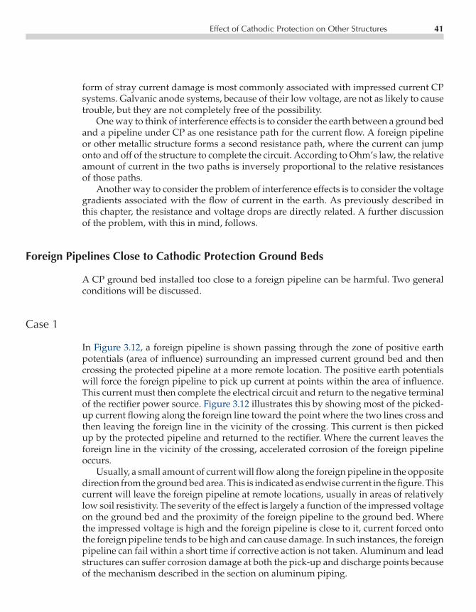
P1: GKW/SPH P2: GKW/UKS P3: GKW/UKS QC: GKW/UKS T1: GKWCE003-03 CE003-Peabody November 3, 2000 9:32 Char Count= 0
Effect of Cathodic Protection on Other Structures 41
form of stray current damage is most commonly associated with impressed current CPsystems. Galvanic anode systems, because of their low voltage, are not as likely to causetrouble, but they are not completely free of the possibility.
One way to think of interference effects is to consider the earth between a ground bedand a pipeline under CP as one resistance path for the current flow. A foreign pipelineor other metallic structure forms a second resistance path, where the current can jumponto and off of the structure to complete the circuit. According to Ohm’s law, the relativeamount of current in the two paths is inversely proportional to the relative resistancesof those paths.
Another way to consider the problem of interference effects is to consider the voltagegradients associated with the flow of current in the earth. As previously described inthis chapter, the resistance and voltage drops are directly related. A further discussionof the problem, with this in mind, follows.
Foreign Pipelines Close to Cathodic Protection Ground Beds
A CP ground bed installed too close to a foreign pipeline can be harmful. Two generalconditions will be discussed.
Case 1
In Figure 3.12, a foreign pipeline is shown passing through the zone of positive earthpotentials (area of influence) surrounding an impressed current ground bed and thencrossing the protected pipeline at a more remote location. The positive earth potentialswill force the foreign pipeline to pick up current at points within the area of influence.This current must then complete the electrical circuit and return to the negative terminalof the rectifier power source. Figure 3.12 illustrates this by showing most of the picked-up current flowing along the foreign line toward the point where the two lines cross andthen leaving the foreign line in the vicinity of the crossing. This current is then pickedup by the protected pipeline and returned to the rectifier. Where the current leaves theforeign line in the vicinity of the crossing, accelerated corrosion of the foreign pipelineoccurs.
Usually, a small amount of current will flow along the foreign pipeline in the oppositedirection from the ground bed area. This is indicated as endwise current in the figure. Thiscurrent will leave the foreign pipeline at remote locations, usually in areas of relativelylow soil resistivity. The severity of the effect is largely a function of the impressed voltageon the ground bed and the proximity of the foreign pipeline to the ground bed. Wherethe impressed voltage is high and the foreign pipeline is close to it, current forced ontothe foreign pipeline tends to be high and can cause damage. In such instances, the foreignpipeline can fail within a short time if corrective action is not taken. Aluminum and leadstructures can suffer corrosion damage at both the pick-up and discharge points becauseof the mechanism described in the section on aluminum piping.

P1: GKW/SPH P2: GKW/UKS P3: GKW/UKS QC: GKW/UKS T1: GKWCE003-03 CE003-Peabody November 3, 2000 9:32 Char Count= 0
42 Cathodic Protection—How It Works
PROTECTEDPIPELINE
RECTIFIER
FOREIGNPIPELINEOR OTHERMETALLICSTRUCTURE
CURRENT FLOWFROM FOREIGNSTRUCTURE TOPROTECTED LINEIN CROSSINGAREA
REMOTEGROUND BED
ENDWISECURRENT
AREA OF INFLUENCE SURROUNDINGGROUND BED. WITHIN THIS AREASOIL POTENTIALS ARE POSITIVE(+) WITH RESPECT TO REMOTEEARTH.
+−
Figure 3.12 Foreign pipeline damaged by CP installa-tion—Case 1.
In cases where the current pickup by the foreign pipeline is not too great, a metallicbond can be installed between the two lines as discussed in Chapter 11. However, severecases may necessitate abandonment of the ground bed when an adequate bond betweenthe two systems circulates so much of the rectifier current through the foreign pipelinethat little is left for CP of the pipeline for which the CP system was installed. Thisemphasizes the need for care in selecting CP installation sites so that conditions such asthese can be avoided.
Case 2
Figure 3.13 illustrates a condition where a foreign pipeline (or other buried metallicstructure) closely approaches a CP ground bed but does not cross the protected pipeline.In this case, as in the preceding case, the foreign pipeline is forced to pick up currentin the area of positive earth potentials surrounding the ground bed. Current will flowendwise along the foreign pipeline in both directions from the ground bed. This straycurrent must then leave the foreign pipeline in more remote areas (such as at areas of lowsoil resistivity) to flow to the protected pipeline and then back to the rectifier to completethe circuit. This means there may be many areas of current discharge and damage to theforeign pipeline rather than a single discharge area as in the preceding case.
Corrective actions may include the use of bond cables from the foreign pipeline to thenegative terminal of the rectifier or the installation of CP systems on the foreign pipelineto reverse the flow of endwise current, all of which are discussed further in Chapter 11.As in the preceding case, current pickup by the foreign pipeline may be so intense that

P1: GKW/SPH P2: GKW/UKS P3: GKW/UKS QC: GKW/UKS T1: GKWCE003-03 CE003-Peabody November 3, 2000 9:32 Char Count= 0
Effect of Cathodic Protection on Other Structures 43
GROUNDBED
AREA OF INFLUENCESURROUNDING THEGROUND BED.
ENDWISECURRENT FLOW.
FOREIGN PIPELINENOT CROSSINGPROTECTED LINE.
CURRENTDISCHARGEFROM FOREIGNPIPELINE INREMOTE AREAS.
PROTECTED PIPELINE
+−
RECTIFIER
Figure 3.13 Foreign pipeline damage caused by CP installa-tion—Case 2.
correction of the condition may not be practical if the ground bed is too close to theforeign pipeline. The ground bed then may have to be abandoned.
In selecting ground bed sites for impressed current systems, the presence of foreignpipelines, which could be adversely affected, must be carefully explored. In areas of highsoil resistivity, where relatively high voltage rectifiers may be used, the area of influencesurrounding a ground bed may extend for several hundred feet. Small units in low-resistivity soil will not create as extensive a problem. In any event, tests must be madeby the corrosion engineer to assure that neighboring pipelines will not be damaged or,if there is some influence, that the possibility of damage can be corrected economically.
In many major metropolitan areas, corrosion control coordinating committees reg-ularly meet to manage interfering systems. The corrosion engineer has an ethical re-sponsibility to inform and cooperate with representatives of neighboring facilities whendesigning and installing a potentially interfering source of stray current. Coordinatingcommittees are discussed further at the end of this chapter.
In the preceding sections, impressed current CP systems were used to illustrate straycurrent corrosion on foreign pipelines because these systems are most likely to promotethis form of corrosion. The same conditions can be established with galvanic anodes butthe anodes would have to be very close to the foreign pipeline for the line to pick upany appreciable portion of their output. This is because the area of influence surround-ing galvanic anodes is relatively small. Nevertheless, the corrosion engineer must makecertain not to establish conditions that will lead to stray current corrosion, regardlessof the type of CP system used. As with impressed current systems, care must be usedin selecting galvanic anode installation sites; however, much closer spacing to foreignpipelines is permissible in most cases. Usually, a spacing of 15 ft would be ample, al-though the corrosion engineer should check for current pickup on foreign structures thisclose. Even closer spacing might be tolerated in instances where tests show that the areaof influence surrounding the galvanic anodes is sufficiently limited.
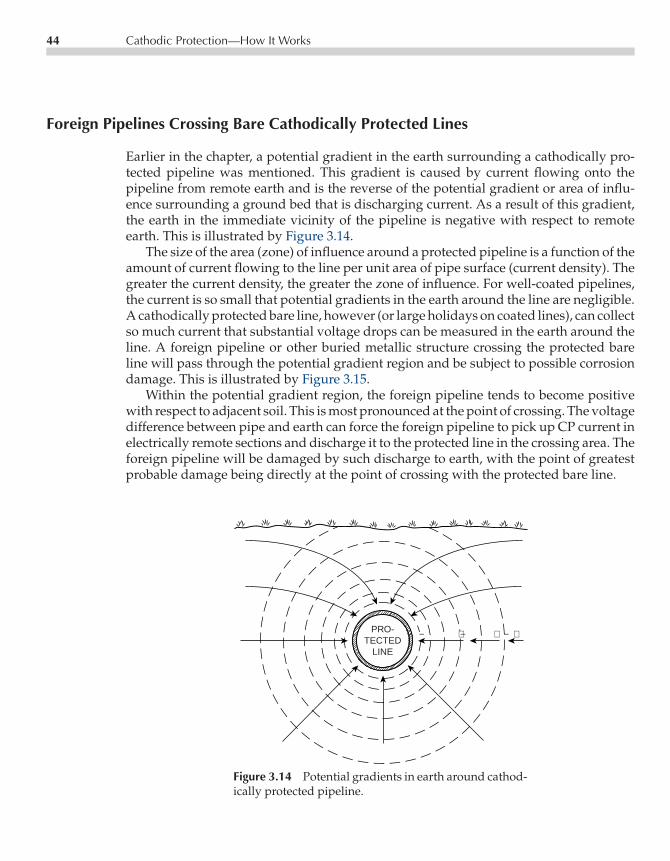
P1: GKW/SPH P2: GKW/UKS P3: GKW/UKS QC: GKW/UKS T1: GKWCE003-03 CE003-Peabody November 3, 2000 9:32 Char Count= 0
44 Cathodic Protection—How It Works
Foreign Pipelines Crossing Bare Cathodically Protected Lines
Earlier in the chapter, a potential gradient in the earth surrounding a cathodically pro-tected pipeline was mentioned. This gradient is caused by current flowing onto thepipeline from remote earth and is the reverse of the potential gradient or area of influ-ence surrounding a ground bed that is discharging current. As a result of this gradient,the earth in the immediate vicinity of the pipeline is negative with respect to remoteearth. This is illustrated by Figure 3.14.
The size of the area (zone) of influence around a protected pipeline is a function of theamount of current flowing to the line per unit area of pipe surface (current density). Thegreater the current density, the greater the zone of influence. For well-coated pipelines,the current is so small that potential gradients in the earth around the line are negligible.A cathodically protected bare line, however (or large holidays on coated lines), can collectso much current that substantial voltage drops can be measured in the earth around theline. A foreign pipeline or other buried metallic structure crossing the protected bareline will pass through the potential gradient region and be subject to possible corrosiondamage. This is illustrated by Figure 3.15.
Within the potential gradient region, the foreign pipeline tends to become positivewith respect to adjacent soil. This is most pronounced at the point of crossing. The voltagedifference between pipe and earth can force the foreign pipeline to pick up CP current inelectrically remote sections and discharge it to the protected line in the crossing area. Theforeign pipeline will be damaged by such discharge to earth, with the point of greatestprobable damage being directly at the point of crossing with the protected bare line.
PRO-TECTED
LINE
+− + − +−
Figure 3.14 Potential gradients in earth around cathod-ically protected pipeline.

P1: GKW/SPH P2: GKW/UKS P3: GKW/UKS QC: GKW/UKS T1: GKWCE003-03 CE003-Peabody November 3, 2000 9:32 Char Count= 0
Effect of Cathodic Protection on Other Structures 45
AREA OFINFLUENCESURROUNDINGPROTECTEDPIPELINE.
FOREIGNPIPELINE
MOST INTENSE CURRENTDISCHARGE AND GREATESTCORROSION DAMAGE TOFOREIGN LINE IS NORMALLYAT POINT OF CROSSING.
FOREIGN LINE TENDSTO BECOME POSITIVETO SOIL WITHIN AREAOF INFLUENCE ANDIS FORCED TO DISCHARGECURRENT.
CURRENTPICKED UPBY FOREIGNPIPELINEOUTSIDE AREAOF INFLUENCE
PROTECTEDPIPELINE.
Figure 3.15 Effect on foreign pipeline passing through earthpotential gradients around cathodically protected bare line.
A foreign pipeline can develop leaks in a short time in extreme instances. If theforeign pipeline happens also to be too close to an impressed current ground bed onthe protected line, as previously discussed, the two effects are additive and the rate ofcorrosion at the point of crossing with the protected line will increase. Damage to theforeign pipeline can occur even if it has a CP system of its own. This takes place if thepotential gradients surrounding the cathodically protected bare line are strong enoughto offset the protective potential on the foreign pipeline and force it to discharge current(and accelerate corrosion) at the point of crossing.
If the foreign pipeline had a perfect coating, there could be no current discharge andno corrosion despite the existence of potential gradients where it passed through thezone of influence around the cathodically protected bare line. This, however, is unlikelyfor typical pipeline coatings and field conditions. Even a single coating defect within thegradient can cause a leak. The rate of penetration would tend to increase with increasingcoating quality because the current discharge would be concentrated at smaller breaksin the coating.
The existence of a possibly damaging effect on a foreign pipeline at a point of crossingcan be ascertained readily. This is accomplished by measuring potentials between theforeign pipe and a close electrode located directly over the foreign line. The measure-ments are obtained at close intervals because the rate of potential change, point-to-point,can be quite rapid. Thus, these measurements simply comprise a close interval surveyof the foreign line in the area near the crossing of the two pipelines. Typically, the plot-ted result will look like Figure 3.16. This figure illustrates the effect on a cathodicallyprotected foreign pipeline and shows a severe potential dip at the point of crossing.

P1: GKW/SPH P2: GKW/UKS P3: GKW/UKS QC: GKW/UKS T1: GKWCE003-03 CE003-Peabody November 3, 2000 9:32 Char Count= 0
46 Cathodic Protection—How It Works
(−)
(+)
0U
NP
RO
TE
CT
ED
PR
OT
EC
TE
D
−0.85 VOLT
POINT OF CROSSINGWITH PROTECTEDBARE LINE.
FOREIGNLINE
AREA OFPOSSIBLE DAMAGE
PROTECTEDBARE LINE
ETC.V
DISTANCE IN FEET ALONG FOREIGN LINE
FO
RE
IGN
PIP
ELI
NE
PO
TE
NT
IAL
TO
CLO
SE
CO
PP
ER
SU
LPH
ATE
ELE
CT
RO
DE
+ −
Figure 3.16 Pipe-to-soil potentials on foreign pipeline pass-ing through area of influence around cathodically protectedbare line.
Damage to the foreign pipeline would be expected unless its coating is perfect. Sucha plot clearly identifies the length of foreign pipeline affected. The length of foreignpipeline subject to depressed potentials can vary from just a few feet in mild cases tohundreds of feet when the potential gradients are severe and the angle between thetwo crossing lines is small. Other factors being equal, the amount of foreign pipelinesubjected to depressed potentials is least for a right-angle crossing.
If there is any question that the potential dip is caused by the CP system on the barepipeline, the CP current sources can be turned off and the potential measurements alongthe foreign pipeline repeated. If the dip disappears, or nearly so, this is adequate proofthat the CP system on the bare line is the cause of the trouble.
Corrective measures are discussed in Chapter 11. Metallic bonds are suitable in someinstances. In other cases, the bare, cathodically protected pipeline may be coated in thevicinity of the crossing to reduce the intensity of potential gradients by locally reducingthe amount of current flow to the pipeline per unit area. Galvanic anodes can be used toadvantage where conditions are favorable, as described in Chapter 11 in the subsectionon use of galvanic anodes.
Sources of Information on Interference
It is desirable, and usually saves considerable time, to seek the help of a corrosion coor-dinating committee when a pipeline is being installed in an area in which a committeeexists. Corrosion coordinating committees are made up of representatives from many of

P1: GKW/SPH P2: GKW/UKS P3: GKW/UKS QC: GKW/UKS T1: GKWCE003-03 CE003-Peabody November 3, 2000 9:32 Char Count= 0
References 47
the principal owners of underground metallic structures in an area (usually a metropoli-tan district where many pipelines cross) that work cooperatively to solve their corrosionproblems. Many of these committees have been in existence for decades and have accu-mulated useful data, maps, and other information that will help avoid the destructiveeffects associated with interfering CP systems. These committees can assist in locatingunderground structures in the area, ascertaining the extent and nature of existing CPsystems, and making cooperative surveys or cooperative contracts for protection.
REFERENCES
R. Rudenberg, Grounding Principles and Practices, I—Fundamental Considerations on GroundCurrents, Electrical Engineering, January 1945.F.E. Stetler, Accelerating Leak Rate in Ductile Cast Iron Water Mains Yields to CP, Materials Perfor-mance, Vol. 19, No. 10, October 1980.C.L. Woody, Is 0.85 Volts to Cu/CuSO4 the Only Criteria for Protection? Collection of papers onUnderground Pipeline Corrosion, Vol. IX, Library of Congress Catalog Number: 59-54031.

P1: GKW/SPH P2: GKW/UKS P3: GKW/UKS QC: GKW/UKS T1: GKWCE003-04 CE003-Peabody November 3, 2000 11:46 Char Count= 0
Chapter4Criteria for CathodicProtection
John A. Beavers and Kevin C. Garrity
In Chapter 3, the theory and principles of how cathodic protection (CP) works werepresented and discussed. To assure that CP is applied in accordance with these principles,criteria and methods of assessment are required. This chapter describes the industry-accepted criteria, and Chapter 5 describes the survey methods and techniques used toassess whether the criteria are met. The discussion below is a review of the NACE criteriapresented in NACE Standard RP-01-69 (1996 Revision) Control of External Corrosion ofUnderground or Submerged Metallic Piping Systems. This document lists criteria and otherconsiderations for CP that will indicate, when used either separately or in combination,whether adequate CP of a metallic piping system has been achieved. The document statesthat the corrosion control programs are not limited to the primary criteria listed: “Criteriathat have been successfully applied on existing piping systems can continue to be usedon those systems. Any other criteria used must achieve corrosion control comparable tothat attained with the criteria herein,” referring to the three primary criteria describedbelow. Other criteria that have been used for underground piping include the 300 mVshift criterion, the E-log I criterion, and the net current flow criterion.
CRITERIA FOR STEEL AND CAST IRON PIPING
Three primary criteria for CP of underground or submerged steel or cast iron piping arelisted in Section 6 of NACE Standard RP-01-69 (1996 Revision):
1. −850 mV (CSE)a with the CP applied,2. A polarized potential of −850 mV (CSE)3. 100 mV of polarization.
aSaturated copper-copper sulfate reference electrode.
49

P1: GKW/SPH P2: GKW/UKS P3: GKW/UKS QC: GKW/UKS T1: GKWCE003-04 CE003-Peabody November 3, 2000 11:46 Char Count= 0
50 Criteria for Cathodic Protection
A fourth criterion, the net protective current criterion, is also listed in Section 6 undera special conditions section, for bare or poorly coated pipelines where long-line corrosionactivity is the primary concern. The application and limitations of each are given below.
−850 mV with Cathodic Protection Applied Criterion
The full criterion states that adequate protection is achieved with:
a negative (cathodic) potential of at least 850 mV with the CP applied. Thispotential is measured with respect to a saturated copper/copper sulfatereference electrode contacting the electrolyte. Voltage drops other thanthose across the structure-to-electrolyte boundary must be considered forvalid interpretation of this voltage measurement. Consideration is under-stood to mean application of sound engineering practice in determiningthe significance of voltage drops by methods such as:
• measuring or calculating the voltage drop(s),• reviewing the historical performance of the CP system,• evaluating the physical and electrical characteristics of the pipe and its
environment• determining whether or not there is physical evidence of corrosion.
Applications
Of the three primary criteria listed above, the first, −850 mV criterion with CP applied,is probably the most widely used for determining if a buried or submerged steel or castiron structure has attained an acceptable level of CP. In the case of a buried steel orcast iron structure, an acceptable level of protection is achieved, based on this criterion,if the potential difference between the structure and a CSE contacting the soil directlyabove and as close as possible to the structure is equal to or more negative than (largerin absolute value) −850 mV. As described above, voltage drops other than those acrossthe structure-to-electrolyte boundary must be considered for valid interpretation of thisvoltage measurement. These voltage drops are a result of current flow in the electrolyte(soil) and are generally referred to as ohmic or IR voltage drops. IR voltage drops aremore prevalent in the vicinity of an anode bed or in areas where stray currents are presentand generally increase with increasing soil resistivity.
For bare or very poorly coated structures, IR voltage drops can be reduced by placingthe reference electrode as close as possible to the structure. For the majority of coatedstructures, most of the IR voltage drop is across the coating, and the measurement is lessaffected by reference electrode placement. The IR voltage drop can also be minimizedor eliminated by interrupting all of the direct current sources of the CP system andmeasuring the instantaneous off-potential. Details on this measurement technique aregiven in Chapter 5. The off-potential will be free of the IR voltage drop errors if all of the

P1: GKW/SPH P2: GKW/UKS P3: GKW/UKS QC: GKW/UKS T1: GKWCE003-04 CE003-Peabody November 3, 2000 11:46 Char Count= 0
Criteria for Steel and Cast Iron Piping 51
current sources, including sources of stray currents, have been properly interrupted andif long-line currents are negligible. Long-line currents occur on a structure as a result ofthe presence of macro-cells, as described in Chapter 1 and Chapter 16. The differencebetween the on- and the off-potential indicates the magnitude of the IR voltage droperror when the measurement is made with the protective current applied.
This criterion was originally adopted based on the observation that the most negativenative potential observed for coated underground steel structures was about −800 mV(CSE). The assumption was made that macro-cell corrosion would be mitigated if suffi-cient CP current were applied to raise (in the negative direction) the potential of the entirestructure to a value that is more negative than the native potential of the local anodicsites. A potential of−850 mV was adopted to provide a 50 mV margin of protection. Theeffectiveness of the criterion has been demonstrated over many years of application.
Limitations
This criterion has a number of limitations. The potential reading should be taken withthe reference electrode contacting the electrolyte directly over the structure, to minimizeohmic voltage drop errors in the measurement and to minimize the extent of averagingover large areas of the structure. Alternative criteria may be required where the refer-ence electrode cannot be properly placed, such as at river crossings or road crossings.The criterion also is most commonly used for well-coated structures, where it can beeconomically met. For poorly coated or bare structures, the high CP currents required tomeet this criterion can be prohibitive, such that alternative criteria are typically used.
Potentials can vary significantly from one area of an underground structure to anotheras a result of variations in soil conditions, coating damage, interference effects, etc. Thiscreates the possibility that potentials less negative than −850 mV (CSE) exist betweenthe measurement points. This problem can be addressed for pipelines by means of close-interval surveys, as described in Chapter 5. If the close-interval survey establishes thatthis problem exists, one should maintain more-negative potentials at the test stations toensure that adequate protection is achieved on the entire structure. However, the morenegative potentials required will result in increased power consumption.
Potentials more negative than −850 mV (CSE) also are required in the presence ofbacteria or with a hot pipeline. In the latter case, the current required for CP can increaseby a factor of two for every 10C (18F) increase in temperature of the pipe. The potentialcriterion is adjusted to compensate for the increased anodic current kinetics. Typically, apotential of−950 mV (CSE) is used for hot pipelines. In the case of microbes, the kineticsof the corrosion reaction and the environment at the pipe surface are altered such that amore-negative potential is typically required to mitigate corrosion. Where the presenceof microbes is confirmed or suspected, a minimum potential criterion of−950 mV (CSE)is typically used. A more detailed discussion of microbially influenced corrosion (MIC)and CP is given in Chapter 14.
Care should be exercised to avoid overprotection, which can result in coating dam-age and may promote hydrogen damage of susceptible steels. The potential above which

P1: GKW/SPH P2: GKW/UKS P3: GKW/UKS QC: GKW/UKS T1: GKWCE003-04 CE003-Peabody November 3, 2000 11:46 Char Count= 0
52 Criteria for Cathodic Protection
coating damage can occur is a function of many variables, including the soil composi-tion and moisture content, the temperature, the coating type, the quality of the coatingapplication, and the presence of microbes. The general consensus in the industry is toavoid polarized (instant off) potentials more negative than −1.05 to −1.1 V (CSE).
The older steels generally contain higher levels of impurities, such as sulfur andphosphorus, and exhibit greater susceptibility to hydrogen damage than do the newer,cleaner steels. In the older steels, the microstructures associated with hard spots andwelds typically are more susceptible to hydrogen damage than is the microstructureof the wrought base metal. Again, the general consensus in the industry is to avoidpolarized (instant off) potentials more negative than −1.05 to −1.1 V (CSE) to minimizehydrogen damage in these steels.
Potentials also can vary seasonally as a result of variation in the soil moisture content.Thus, some pipeline companies perform annual surveys at the same time each year, sothat trends in the behavior of a pipeline can be properly interpreted. This approach doesnot, however, preclude the possibility that the criterion is not being met on some partsof the structure during portions of the year.
Limitations also exist in the ability to accurately measure the potential of the struc-ture in the presence of telluric currents or where shielding by disbonded coatings, rocks,thermal insulation, etc., has occurred. Similarly, the accuracy of the potential measure-ment is compromised by stray currents that cannot be interrupted or by the presence ofmultiple pipelines in a right-of-way where the pipelines have varied coating conditions.
Dynamic stray currents, from sources such as DC transit systems and mining activi-ties, pose a significant challenge in applying this criterion. Where dynamic stray currentsare suspected, it is generally necessary to obtain potential values over the duration ofthe stray current activity, typically for twenty-four hours or longer. For example, for DCtransit systems, it is often possible to obtain fairly stable on-potentials of the structure inthe early morning hours when the transit system is not operating. These potentials canprovide baseline data for use in evaluating other measurements. Of course, appropri-ate interpretation of such data is required. DC stray currents not only affect the abilityto obtain accurate off-potentials, but also influence the polarized potential of the pipe.Nevertheless, the −850 mV criterion with CP applied is the criterion most commonlyused in areas of significant dynamic stray current activity. It is generally accepted thatthe structure is protected at a test location if the potential of the structure remains morenegative than −850 mV (CSE) at all times, even with significant fluctuations associatedwith the dynamic stray currents. It may be necessary to increase the number of test pointsand the frequency of surveys in areas of dynamic stray DC currents.
Polarized Potential of −850 mV Criterion
This criterion states that adequate protection is achieved with “a negative polarizedpotential of at least 850 mV relative to a saturated copper/copper sulfate referenceelectrode.” The polarized potential is defined as the “potential across the struc-ture/electrolyte interface that is the sum of the corrosion potential and the cathodic

P1: GKW/SPH P2: GKW/UKS P3: GKW/UKS QC: GKW/UKS T1: GKWCE003-04 CE003-Peabody November 3, 2000 11:46 Char Count= 0
Criteria for Steel and Cast Iron Piping 53
−600
−700
−800
−900
−1000
−1100
−1200
0 50 100 150 200 250 300 350
On Potential, mVOff Potential, mVNative Potential, mV-850 mV Criterion
Po
ten
tial
, - m
V (
Co
pp
er C
op
per
Su
lfat
e)
Distance, Meters
Figure 4.1 Close interval survey data showing on, off, and native potentials.
polarization.” The polarized potential is measured directly after the interruption of allcurrent sources and is often referred to as the off- or instant off-potential. The differencein potential between the native potential and the off or polarized potential is the amountof polarization that has occurred as a result of the application of the CP. As previouslystated, the difference in potential between the on-potential and the off-potential is theerror in the on-potential introduced as a result of voltage drops in the electrolyte (soil)and the metallic return path in the measuring circuit. Typical close interval survey datashowing these potentials are given in Figure 4.1.
Applications
This second criterion is more direct than the−850 mV criterion with CP applied by clearlydefining the method by which voltage drops errors in the on-potential are considered.In the second criterion, these errors are minimized or eliminated. The voltage droperrors, which are often referred to as ohmic potential drop or IR drop errors, occur as aresult of the flow of CP or stray current in the electrolyte (soil) or in the structure. Theyare measurement errors because the cathodic polarization at the structure-to-electrolyteinterface is the only part of the on-potential measurement that contributes to a reductionin the rate of corrosion of the structure. As described above, polarization is defined as thedifference in potential between the native potential and the off- or polarized potential;it is referred to as cathodic polarization if the potential shift is in the negative direction.

P1: GKW/SPH P2: GKW/UKS P3: GKW/UKS QC: GKW/UKS T1: GKWCE003-04 CE003-Peabody November 3, 2000 11:46 Char Count= 0
54 Criteria for Cathodic Protection
This criterion is most commonly applied to coated structures where the sources of DCcurrent can be readily interrupted. An example would be an FBE-coated gas transmissionpipeline in a rural area with an impressed current CP system.
Limitations
An important limitation of this criterion is the requirement that all sources of DC currentbe interrupted. For standard survey techniques, the interruption must be performedsimultaneously on all current sources. On gas transmission pipelines, interrupting allcurrent sources may require the use of a large number of synchronous interrupters forall rectifiers, sacrificial anodes, and bonds affecting the section of pipeline that is beingevaluated. In some cases, the number of rectifiers affecting a test section is not knownwithout experimental verification. On gas distribution systems, sacrificial anodes aremore commonly used for CP and the electrical leads for the anodes are usually bondeddirectly to the pipe with no means available to interrupt the current. For those situations,this criterion cannot be used. Achieving the criterion also may require the applicationof high CP currents, resulting in overprotection of some portions of the structure andrelated problems such as cathodic disbondment of coatings and hydrogen embrittlementof susceptible steels. As described above, a potential more negative than−850 mV (CSE)may be required to mitigate corrosion on hot pipelines or in the presence of MIC, furtherincreasing the likelihood of overprotection.
Many of the difficulties of accurately measuring pipe-to-soil potentials that were de-scribed under limitations to the−850 mV criterion with CP applied apply to the polarizedpotential of −850 mV criterion as well. These include access to the structure, seasonalfluctuations in the potential between testing times, spatial fluctuations in potential be-tween test stations, the presence of multiple pipelines with different levels of coatingquality in a right-of-way, telluric current effects, and shielding of the structure surfaceby disbonded coatings, rocks, and thermal insulation.
100 mV of Polarization Criterion
This criterion states that adequate protection is achieved with “a minimum of 100 mVof cathodic polarization between the structure surface and a stable reference electrodecontacting the electrolyte. The formation or decay of polarization can be measured tosatisfy this criterion.” Of the three criteria, this criterion has the most sound fundamentalbasis. As described in Chapters 3 and 16, the corrosion rate decreases and the rate ofthe reduction reaction on the metal surface increases as the underground structure ispolarized in the negative direction from the native potential. The difference between thecorrosion rate (expressed as a current) and the rate of the reduction reaction is equalto the applied CP current. These processes can be shown graphically in a diagram of Eversus log I, referred to as an Evans diagram (see Chapter 16). The slope of the anodic

P1: GKW/SPH P2: GKW/UKS P3: GKW/UKS QC: GKW/UKS T1: GKWCE003-04 CE003-Peabody November 3, 2000 11:46 Char Count= 0
Criteria for Steel and Cast Iron Piping 55
(corrosion) reaction is referred to as the anodic Tafel slope and typically has a value of∼100 mV per decade of current. With this Tafel slope, the corrosion rate of a structuredecreases by a factor of 10 (an order of magnitude) for every 100 mV cathodic shiftin the polarized potential. An order of magnitude decrease in the corrosion rate of anunderground structure typically is more than adequate to effectively mitigate corrosion.
The cathodic polarization also promotes beneficial changes in the environment at thepipe surface, such as reducing oxygen, increasing the pH, and moving halides such aschlorides away from the metal surface, which further decreases the corrosion rate. Thesebeneficial changes in the environment at the metal surface are referred to as environmen-tal polarization, in that the environmental changes typically result in a shift in the freecorrosion potential of the pipe in the negative direction. Thus, the total potential shiftfrom the native potential (excluding IR voltage drops in the soil) includes componentsattributable to environmental polarization and cathodic polarization.
As described in the criterion, the magnitude of the polarization shift can be deter-mined by measuring its formation or decay. To determine the magnitude of the shift asa result of the formation of polarization, one must first determine the native potentialof the underground structure at test locations before applying CP. The potential is thenre-measured after the CP system is energized and the structure has had sufficient timeto polarize. Typically, the on-potential is continuously monitored at one test locationdirectly after energization the CP system, and an off-potential reading is made whenthere is no measurable shift in the on-potential reading for several minutes. The off-potential is then compared with the native potential; if the difference exceeds 100 mV,then the 100 mV criterion has been satisfied at that location. These measurements areshown graphically in Figure 4.2. Off-potential readings are then obtained at the other testlocations to determine whether the criterion is met at these locations. The time requiredfor sufficient polarization to develop is highly dependent on the nature of the structure(coating condition, underground environment, types and number of bonds, and so forth)and the design of the CP system. From a practical standpoint, it is wise to reexaminethe overall structure and the CP system if a reasonable amount of polarization does notdevelop within a few hours of energizing the CP system.
An alternative method of assessing the formation of cathodic polarization is to mea-sure the on-potential immediately after energizing the CP system and then re-measurethe on-potential after a few hours to days of operation. If the on-potential shifts in thecathodic (negative) direction by >100 mV, then one can conservatively assume that thecriterion has been met. Because the applied CP current generally decreases with time,the magnitude of the IR voltage drop also decreases. Thus, the total shift in the on-potential must be a result of the sum of the additional cathodic polarization and theenvironmental polarization of the pipeline, both of which reduce the corrosion rate ofthe structure and are included in the 100 mV of polarization in the criterion. If thismethod is used, the engineer should confirm that the applied CP current decreased withtime.
Measuring the positive potential shift associated with polarization decay that occursafter de-energizing the CP system is the most common method to determine the amount

P1: GKW/SPH P2: GKW/UKS P3: GKW/UKS QC: GKW/UKS T1: GKWCE003-04 CE003-Peabody November 3, 2000 11:46 Char Count= 0
56 Criteria for Cathodic Protection
Native Potential
Eoff
Eon
CP SystemTurned Off
CP SystemTurned On
Time
0
−200
−400
−600
−800
−1000
Pot
entia
l, m
V (
Cop
per
Cop
per
Sul
fate
)
Figure 4.2 Pipe-to-soil potential as a function of time following energizingCP system.
of polarization. Figure 4.3 is a schematic that shows the pipe-to-soil potential follow-ing de-energizing of a CP system. When a CP system is de-energized, the pipe-to-soilpotential undergoes an instantaneous positive shift as a result of elimination of the IRvoltage drop in the soil. The potential measured at this time is referred to as the off-potential, as previously described, and is used as the starting point for assessing thepolarization shift. There may be a spike in the potential reading immediately after inter-ruption of the CP system, a result of inductive effects of the pipeline and the CP system.Because this spike may last a few hundred milliseconds, the off-potential is typicallymeasured 200 to 500 ms after the interruption.
The potential will then exhibit an exponential decay with time in the positive directionas the capacitor across the structure-to-electrolyte boundary discharges. This componentof the potential shift is the cathodic polarization of the structure as a result of the appliedcathodic current. A gradual linear decay in the potential will then occur over minutesto weeks as a result of a return of the environment at the pipe surface to its nativecondition. This component of the potential shift is the environmental polarization. Toobtain the total polarization shift, the final potential after polarization decay is measured

P1: GKW/SPH P2: GKW/UKS P3: GKW/UKS QC: GKW/UKS T1: GKWCE003-04 CE003-Peabody November 3, 2000 11:46 Char Count= 0
Criteria for Steel and Cast Iron Piping 57
Time, Seconds
CP System Interrupted
CathodicDepolarization
EnvironmentalDepolarization
EoffEon
2 4 6 8 10
0
−200
−400
−600
−800
−1000
Pot
entia
l, m
V (
Cop
per
Cop
per
Sul
fate
)
Figure 4.3 Pipe-to-soil potential as a function of time following de-energizingCP system.
and subtracted from the off-potential. If this difference is>100 mV, then the criterion hasbeen satisfied.
Applications
The 100 mV polarization criterion is most commonly used on poorly coated or barestructures where it is difficult or costly to achieve either of the−850 mV criteria. In manycases, 100 mV of polarization can be achieved where the off-potential is less negative than−850 mV (CSE). The application of the 100 mV polarization criterion has the advantage ofminimizing coating degradation and hydrogen embrittlement, both of which can occuras a result of overprotection. In piping networks, the 100 mV polarization criterion canbe used for the older, poorly coated pipes; whereas, a−850 mV (CSE) polarized potentialcriterion can be used for the newer piping in the network. Because of its fundamentalunderpinnings, the 100 mV polarization criterion also can be used on metals other thansteel, for which no specific potential required for protection has yet been established.

P1: GKW/SPH P2: GKW/UKS P3: GKW/UKS QC: GKW/UKS T1: GKWCE003-04 CE003-Peabody November 3, 2000 11:46 Char Count= 0
58 Criteria for Cathodic Protection
Limitations
This criterion has several limitations. The time required for full depolarization of a poorlycoated or bare structure can be several days to several weeks, making the method verytime-consuming and leaving the structure unprotected for an extended period of time.Fortunately, much of the depolarization occurs within a few hours and waiting for thefull decay frequently is not necessary, except where the total polarization is very closeto 100 mV. Once the criterion has been met, it is not necessary to continue waiting forfurther depolarization. At the other extreme, if a depolarization of<50 mV is measuredwithin a few hours, it is questionable whether the 100 mV polarization criterion canbe achieved. At this point, it may be prudent to assess whether a longer wait for totaldepolarization is justified.
The 100 mV polarization criterion is frequently used to minimize the costs for up-grading CP systems, and the associated increase in power costs, in areas with degradingcoatings. Because of the complicated nature of the measurements, the cost of conductingsurveys for the assessment of the 100 mV polarization criterion is considerably higherthan for the−850 mV criteria. Thus, an economical analysis may be required to determinewhether an actual cost savings is associated with application of the 100 mV polarizationcriterion.
The 100 mV polarization criterion should not be used in areas subject to stray currentsbecause 100 mV of polarization may not be sufficient to mitigate corrosion in these areas.It is generally not possible to interrupt the source of the stray currents to accuratelymeasure the depolarization. To apply this criterion, all DC current sources affecting thestructure, including rectifiers, sacrificial anodes, and bonds must be interrupted. In manyinstances, this is not possible, especially on the older structures for which the criterionis most likely to be used.
The 100 mV polarization criterion should not be used on structures that containdissimilar metal couples because 100 mV of polarization may not be adequate to protectthe active metal in the couple. This criterion also should not be used in areas wherethe intergranular form of external stress corrosion cracking (SCC), also referred to ashigh-pH or classical SCC, is suspected. The potential range for cracking lies between thenative potential and −850 mV (CSE) such that application of the 100 mV polarizationcriterion may place the potential of the structure in the range for cracking.
Net Protective Current Criterion
RP0169-96 (latest revision) states under paragraph 6.2.2.2 (Special Conditions): “On bareor ineffectively coated pipelines where long-line corrosion activity is of primary concern,the measurement of a net protective current at predetermined current discharge pointsfrom the electrolyte to the pipe surface, as measured by an earth current technique, maybe sufficient” for CP to be achieved.
This statement establishes the fourth criterion for CP of underground piping, referredto as the net protective current criterion. This criterion was originally based on the

P1: GKW/SPH P2: GKW/UKS P3: GKW/UKS QC: GKW/UKS T1: GKWCE003-04 CE003-Peabody November 3, 2000 11:46 Char Count= 0
Criteria for Steel and Cast Iron Piping 59
concept that if the net current at any point on a structure is flowing from the electrolyteto the structure, there cannot be any corrosion current discharging from that point onthe structure. The theory of electrochemical kinetics, described in Chapter 16, shows thatcorrosion can occur at a point on a structure that is collecting net cathodic current fromthe electrolyte, as long as the polarized potential is more positive than the equilibriumpotential. Nevertheless, the criterion can be effective, from a practical standpoint, becausethe collection of net cathodic current at any point along the structure produces beneficialcathodic polarization and also promotes beneficial changes in the environment at thestructure surface, as described above.
Typically, the criterion is applied by first performing, with the CP system de-energized, a close-interval pipe-to-soil potential survey, or a cell-to-cell potential surveyto locate the anodic discharge points along the pipeline. Further details on these surveymethods are given in Chapter 5. For the surveys to be effective, the CP systems mustbe de-energized long enough for all polarization to decay. The CP system is then ener-gized and the structure is allowed to polarize. A side drain method is then used at theanodic discharge points to determine whether the structure is receiving cathodic currentat these locations. With the side drain method, the potential difference between an elec-trode placed directly over the structure and one placed on either side of the structureis measured. If the electrode located over the pipe is negative with respect to the othertwo electrodes, then current is collecting on the pipe at the location and the criterion issatisfied.
Applications
The net protective current criterion is normally used on poorly coated or uncoatedpipelines, where the primary concern is long-line corrosion activity. The technique alsois normally only used in situations where other criteria cannot be easily or economicallymet. With these exceptions, this criterion is not a standard criterion for establishing theeffectiveness of a CP system.
Limitations
There are a number of limitations to this criterion. First and foremost is the fact thatthe criterion essentially states that any magnitude of net current flow to the structure(and therefore, any amount of cathodic polarization of the structure) is adequate tomitigate corrosion. In general, that is not the case and therefore, the criterion should beconsidered for use only as a last resort. Application of the criterion should be avoided inareas of stray current activity or in common pipeline corridors because of the possibilityof misinterpretation of the potential readings. The criterion also may not be effectivein areas with high-resistivity soils, for deeply buried pipelines, or where the separationdistance of the corrosion cells is small. Finally, the side drain measurements at a givenlocation are indicative of the direction of current flow at that location only and are notnecessarily representative of behavior elsewhere on the pipeline. Thus, for the application

P1: GKW/SPH P2: GKW/UKS P3: GKW/UKS QC: GKW/UKS T1: GKWCE003-04 CE003-Peabody November 3, 2000 11:46 Char Count= 0
60 Criteria for Cathodic Protection
of this criterion, it is generally necessary to perform side drain measurements at closeintervals (2 to 20 ft) along the pipeline.
Other Criteria for Steel and Cast Iron
The four criteria listed for steel and cast iron piping are the only acceptable criteria listedin RP-01-69-96 for underground or submerged metallic piping. However, other criteriacan be used on a piping system for which they have been used in the past and it canbe demonstrated that their use has resulted in effective CP. Other criteria are also usefulfor underground structures such as reinforced concrete pipe and piling. The two mostcommon other criteria that have been used in the past for underground structures arethe 300 mV potential shift criterion and the E-log I curve criterion.
300 mV Potential Shift Criterion
The 300 mV potential shift criterion was contained in the original version of RP 01-69and stated that adequate protection is achieved with “a negative (cathodic) voltage shiftof at least 300 mV as measured between the structure surface and a saturated copper-copper sulfate half cell contacting the electrolyte. Determination of this voltage shift isto be made with the protective current applied.” This criterion is similar to the 100 mVpolarization criterion, which is assessed on the basis of the formation of polarization ona structure. With both criteria, it is first necessary to determine the native potential ofthe underground structure at test locations before CP is applied. The potential is thenre-measured after the CP system is energized and the structure has had sufficient time topolarize. The difference between the two criteria is that, in the case of the 300 mV potentialshift criterion, the on-potential is used for assessment of the criterion; whereas, in the caseof the 100 mV polarization criterion, the off-potential is used for assessment. Regardingthe 300 mV potential shift criterion, the standard states “The Corrosion Engineer shallconsider voltage (IR) drops other than those across the structure-electrolyte boundaryfor valid interpretation of the voltage measurements.” Thus the relationship between the300 mV potential shift criterion and the 100 mV polarization criterion is analogous to therelationship between the −850 mV (CSE) with CP applied criterion and the polarizedpotential of −850 mV (CSE) criterion.
The 300 mV potential shift criterion has mainly been used for mitigation of moderaterates of uniform corrosion of bare steel pipelines. It has been applied for protection ofentire pipelines and also for hot-spot protection. On these pipelines, native potentials of−200 to −500 mV (CSE) are common and a 300 mV shift has been found to be adequateto mitigate corrosion in some instances. Thus, the development of the criterion wasempirically based. The 300 mV potential shift criterion is more applicable to impressedcurrent CP systems than to galvanic anode systems because galvanic anodes may nothave sufficient driving voltage to meet the criterion when negative native potentials areencountered.

P1: GKW/SPH P2: GKW/UKS P3: GKW/UKS QC: GKW/UKS T1: GKWCE003-04 CE003-Peabody November 3, 2000 11:46 Char Count= 0
Criteria for Steel and Cast Iron Piping 61
Probably the most successful application of this criterion has been on steel reinforcedconcrete structures. These structures typically have native potentials in the range of−200to −400 mV (CSE) and passive steel surfaces, with the exception of hot spots, such thata potential shift of 300 mV can be readily achieved. Application of this criterion avoidsproblems associated with overprotection.
Many of the limitations associated with the 100 mV polarization criterion are appli-cable to the 300 mV potential shift criterion as well. These include the time required forpolarization, the possibility of moving the potential into the cracking range for SCC,and difficulties in areas containing stray currents or galvanic couples. In general, the300 mV potential shift criterion should not be used where high-pH SCC is confirmed orsuspected, or where stray currents or galvanic couples are present. The original versionof RP 01-69 states, “This criterion of voltage shifts applies to structures not in contactwith dissimilar metals.”
Probably the single greatest limitation of the 300 mV potential shift criterion is thatsituations will exist in the field where the criterion will appear to be applicable yetcorrosion may not be mitigated. In some situations, the majority of the potential shiftwill be the result of IR voltage drops in the soil or across the coating, and very littlepolarization of the structure will occur. For this reason, the criterion was removed fromthe primary list of criteria in the 1992 and 1996 revisions of RP-01-69.
E-Log I Curve Criterion
The E-log I curve criterion also is found in the original version of RP-01-69, which statesthat adequate protection is achieved with “a voltage at least as negative (cathodic) asthat originally established at the beginning of the Tafel segment of the E-log I curve. Thisvoltage shall be measured between the structure surface and a saturated copper-coppersulfate half cell contacting the electrolyte.” The criterion was originally developed basedon an incorrect interpretation of a plot of potential versus the log of the current (E-log Icurve). The cathodic E-log I curve, which is generated as a structure is polarized from thenative potential, was thought to exhibit a break that had some fundamental significance.This break was thought to occur at the beginning of the Tafel region. A review of thetheory of CP, given in Chapter 16, indicates that the net cathodic current measured at anyapplied cathodic potential is equal to the difference between the rate of the reductionreaction and the rate of the oxidation reaction. An E-log I curve shows a smooth transitionfrom zero current, at the native potential, to the linear Tafel region. The Tafel region startswhen the rate of the oxidation (corrosion) reaction is negligibly small in comparison withthe rate of the reduction reaction. Depending on the Tafel slopes for the oxidation andreduction reactions, the beginning of the Tafel region can vary between 50 and 100 mVcathodically from the native potential.
At present, the E-log I curve criterion is rarely used for evaluating existing CP sys-tems. However, the measurement technique, originally developed for applying the E-logI curve criterion, is now most commonly used to determine the minimum current re-quired for protection. The pipe-to-soil potential, determined by using a remote reference

P1: GKW/SPH P2: GKW/UKS P3: GKW/UKS QC: GKW/UKS T1: GKWCE003-04 CE003-Peabody November 3, 2000 11:46 Char Count= 0
62 Criteria for Cathodic Protection
electrode, is plotted as a function of the current output of a CP system. Typically, it isnecessary to use an interruption technique and off-potentials for constructing the E-log Iplot in order to accurately establish the curve. The potential required to achieve a desiredminimum current value is identified on the curve. This value should be at least as nega-tive as the value at the beginning of the Tafel region of the E-log I curve. Once the potentialand current values have been established, future surveys consist of checking the currentoutput of the CP system and the potential of the structure with respect to the remotereference electrode, placed in the same location as was used in the original E-log I tests.
Because of the elaborate nature of the technique, its use is generally limited to struc-tures where conventional means of assessment are difficult. Examples include rivercrossings for pipelines, well casings, and piping networks in concentrated areas suchas industrial parks. The technique can give erroneous results in areas of stray currents.The reference electrode must be placed in the same location each time the potential ismeasured. Furthermore, there is no guarantee that a repeat E-log I curve will yield thesame results as the original curve.
CRITERION FOR ALUMINUM PIPING
RP0169-96, lists a single criterion for aluminum piping, identical to the 100 mV polariza-tion criterion used for cast iron and steel. According to paragraph 6.2.3.1, “The followingcriterion shall apply; a minimum of 100 mV of cathodic polarization between the struc-ture and a stable reference electrode contacting the electrolyte. The formation or decayof this polarization can be used in this criterion.”
Two precautionary notes included in Section 6.2.3.2 are unique to aluminum piping:one dealing with excessive voltages (paragraph 6.2.3.2.1) and one dealing with alkalineconditions (paragraph 6.2.3.2.2).
Paragraph 6.2.3.2.1, states that:
Notwithstanding, the minimum criterion in Section 6.2.3.1, if aluminumis cathodically protected at voltages more negative than −1200 mV mea-sured between the pipe surface and a saturated copper/copper sulfatereference electrode contacting the electrolyte and compensation is madefor the voltage drops other than those across the pipe-electrolyte bound-ary, it may suffer corrosion as a result of the buildup of alkali on the metalsurface. A polarized potential more negative than −1200 mV should notbe used unless previous test results indicate that no appreciable corrosionwill occur in the particular environment.
Paragraph 6.2.3.2.2 states that:
Aluminum may suffer from corrosion under high-pH conditions and ap-plication of CP tends to increase the pH at the metal surface. Therefore,

P1: GKW/SPH P2: GKW/UKS P3: GKW/UKS QC: GKW/UKS T1: GKWCE003-04 CE003-Peabody November 3, 2000 11:46 Char Count= 0
Criterion for Copper Piping 63
careful investigation or testing should be made before applying CP to stoppitting attack on aluminum in environments with a natural pH in excessof 8.0.
The basis for these cautionary notes is the incompatibility of aluminum in high-pHenvironments. The protective passive films on aluminum break down in high-pH elec-trolytes, leading to significant increases in the corrosion rate, even at relatively negativepotentials. In addition to these precautionary notes, several of the limitations for the100 mV polarization criterion for steel and cast iron also apply to aluminum. Theseinclude the time-consuming nature of the measurement technique, difficulties associ-ated with interrupting all current sources, and limitations in applying the criterion tostructures with dissimilar metals and in the presence of stray currents. Because no othercriterion is applicable to aluminum, good engineering practice must be used to addressthese limitations. For example, sources of stray current should be identified and elim-inated, if possible. Aluminum piping should be isolated from other metals before CPis applied (isolation of aluminum is required for the CP criterion of dissimilar metalsunder Section 6.2.5 of RP0169; see below).
CRITERION FOR COPPER PIPING
RP0169-96 has a single criterion for copper piping. According to paragraph 6.2.4.1, “Thefollowing criterion shall apply; a minimum of 100 mV of cathodic polarization betweenthe structure and a stable reference electrode contacting the electrolyte. The formationor decay of this polarization can be used in this criterion.”
This criterion is identical to the 100 mV polarization criterion used for cast iron,steel, and aluminum. There are no precautionary notes with this criterion, but several ofthe limitations with the 100 mV polarization criterion for steel and cast iron also applyto copper. These include the time-consuming nature of the measurement technique,difficulties associated with interrupting all current sources, and limitations in applyingthe criterion on structures with dissimilar metals and in the presence of stray currents.Sources of stray current should be identified and eliminated, if possible. Because copper isa noble metal, steel, cast iron, or other metals usually will undergo preferential galvanicattack when coupled to copper. Therefore, it is desirable to eliminate such dissimilarmetal couples before applying CP.
Criterion For Dissimilar Metal Piping
RP0169-96 contains a single criterion for dissimilar metal piping. Under paragraph6.2.5.1, the following criterion is listed: “A negative voltage between all pipe surfacesand a stable reference electrode contacting the electrolyte equal to that required for theprotection of the most anodic metal should be maintained.”

P1: GKW/SPH P2: GKW/UKS P3: GKW/UKS QC: GKW/UKS T1: GKWCE003-04 CE003-Peabody November 3, 2000 11:46 Char Count= 0
64 Criteria for Cathodic Protection
There is one precautionary note, under Paragraph 6.2.5.2: “Amphoteric materials thatcould be damaged by high alkalinity created by CP should be electrically isolated andseparately protected.” Amphoteric metals include aluminum, titanium, and zirconium.
In practice, this criterion applies only where carbon steel or cast iron is coupled to amore noble metal such as copper. In this situation, either of the 850 mV criterion wouldapply: −850 mV (CSE) with the CP applied or a polarized potential of −850 mV (CSE).Other criteria, such as the 100 mV of polarization criterion would not be applicable.

P1: LKC/FQA P2: FPVCE003-05 CE003-Peabody November 13, 2000 11:28 Char Count= 0
Chapter5Survey Methods andEvaluation Techniques
Ronald L. Bianchetti
Various testing methods and techniques may be used on underground pipelines duringthe course of field surveys.
DATA ASSEMBLED BEFORE STARTING A FIELD SURVEY
Before any field survey, the corrosion engineer should gather as much information aspossible about the pipeline to be studied. This may provide valuable data on corrosionconditions to be expected and should be helpful in planning a survey program that willyield useful data for design purposes.
The following items of information are typical of those which should be accumulatedbefore planning and starting the field survey.
• Pipe material: Steel (including grade of steel), cast iron, wrought iron, or other materialof known electrical resistance.
• Is the line bare or coated? If coated, what is the coating material and what coatingspecifications were used?
• If it is an existing line, is there a leak record? If so, information on the location anddate of occurrence of each leak will positively indicate the more serious problemareas.
• Pipe diameter, wall thickness, and weight per foot; data on any changes in these itemsalong the route of the line.
• Size or sizes of casing pipe used, with wall thickness or weight per foot; grade ofsteel used; data on insulators used between pipe and casing and on casing end
65

P1: LKC/FQA P2: FPVCE003-05 CE003-Peabody November 13, 2000 11:28 Char Count= 0
66 Survey Methods and Evaluation Techniques
seals; if coated casing was or is to be used, type of coating and application specifica-tions.
• Location and construction details of all corrosion test points that have been installedalong the line. If no test points have been installed for corrosion test purposes, deter-mine locations where contact can be made with the pipeline for test purposes (otherthan by driving contact bars down to the pipe).
• Is the line of all-welded construction, or are mechanical couplers used?• Location of branch taps.• Location of insulated flanges or couplers, if any, purposely used to sectionalize the
line or to isolate it electrically from other portions of the system or from piping ofother ownership.
• Route maps and detail maps giving as much data as is available.• Location of underground structures of foreign ownership that cross the pipeline to be
surveyed; if any of these structures are cathodically protected, determine the locationof cathode protection (CP) current sources (particularly rectifiers) that may be closeto the line being surveyed.
• Location of possible sources of man-made stray current (such as DC electric transitsystems or mining operations) that could affect the line under study.
• Do any sections of the pipeline closely parallel (within 200 ft or so) high voltageelectric transmission lines? If so, what is the length of such exposure, how close isthe pipeline to the towers, at what voltage does the electric line operate, and whatmethod is used for grounding the towers? (This information is significant becauserectifier installations and insulated joints in well-coated pipes closely parallel to highvoltage electric lines may be damaged by induced AC voltage surges under electricsystem fault conditions if preventive measures are not taken.)
• Is the line now operated at elevated temperature or will it be so operated in theforeseeable future. (High temperature could cause deterioration of coatings used.)
SURVEY METHODS AVAILABLE
The actual field survey should be organized to use several or all of the following pro-cedures. The actual selection and the relative importance of data obtained from eachmethod selected will depend on the particular situation. Survey methods for differentsituations are listed below to guide the corrosion engineer. These tests should supple-ment information gathered under Data Assembled Before Starting a Field Survey.
Survey of Pipeline Routes before Construction
• Measurement of the electrical resistivity of the soil environment around the pipeline• Determination of conditions suitable for anaerobic bacterial corrosion

P1: LKC/FQA P2: FPVCE003-05 CE003-Peabody November 13, 2000 11:28 Char Count= 0
Measurement Procedures and Survey Methods 67
• Determination of various chemical constituents in the soil environment (chlorides,sulfate, sulfides, bicarbonates)
Survey of Pipeline Not under Cathodic Protection
• Measurement of the electrical resistivity of the soil environment around the pipeline• Determination of conditions suitable for anaerobic bacterial corrosion• Determination of various chemical constituents in the soil environment (chlorides,
sulfate, sulfides, bicarbonates)• Potential surveys: measurements of potentials between pipeline and environment• Line current survey: measurement of electrical current flowing on the pipeline• Measurement of the effective electrical resistance of any coating on the pipeline being
studied• Bellhole examinations for evidence of corrosion activity• Use of recording instruments for the study of unstable (stray current) conditions• If cathodic protection (CP) is deemed necessary: evaluation of electric current require-
ments for CP.
Survey of Pipeline under Cathodic Protection
• Potential surveys: measurements of potentials between pipeline and environment• Line current survey: measurement of electrical current flowing on the pipeline• Measurement of the effective electrical resistance of any coating on the pipeline being
studied• Bellhole examinations for evidence of corrosion activity• Use of recording instruments for the study of unstable (stray current) conditions
From the listings above, a corrosion survey might seem to be a rather involved process.It is the responsibility of the corrosion engineer to select the proper survey “tools” thatwill be best suited for a specific situation and provide adequate design information atthe least expense. It is easily possible to “overengineer” corrosion surveys and to putthe greatest emphasis on what may turn out to be relatively unimportant data. This iswhere knowledge and—particularly—experience are important.
MEASUREMENT PROCEDURES AND SURVEY METHODS
In this section, we will discuss some of the more important field test measurement proce-dures for typical test equipment described in Chapter 6. These measurements procedureswill be incorporated into survey methods commonly utilized for assessing pipelines bothwith and without CP.
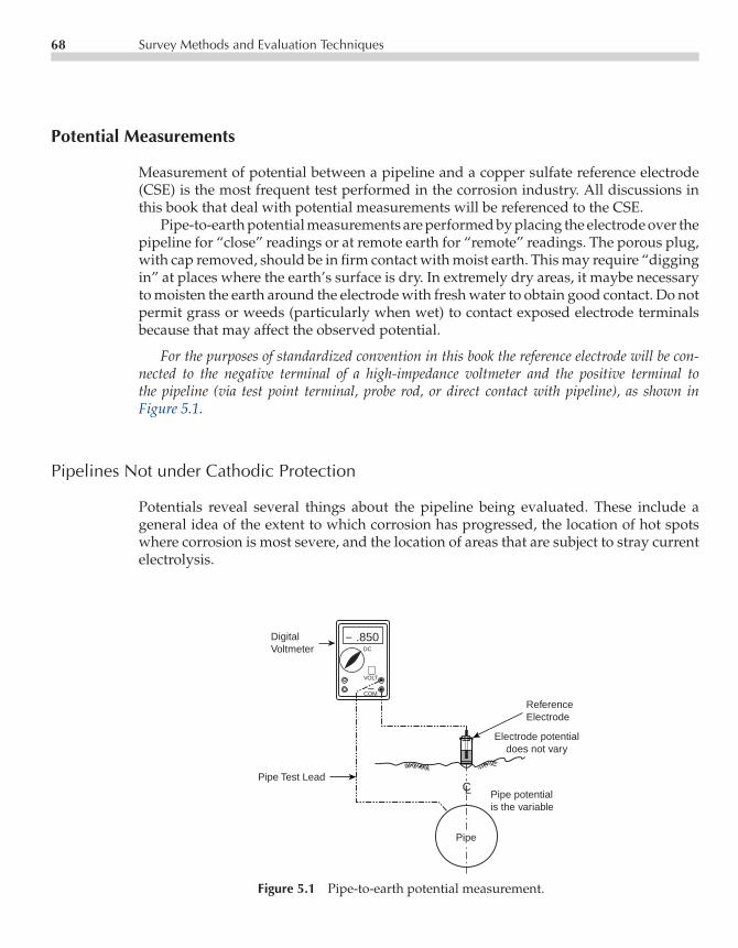
P1: LKC/FQA P2: FPVCE003-05 CE003-Peabody November 13, 2000 11:28 Char Count= 0
68 Survey Methods and Evaluation Techniques
Potential Measurements
Measurement of potential between a pipeline and a copper sulfate reference electrode(CSE) is the most frequent test performed in the corrosion industry. All discussions inthis book that deal with potential measurements will be referenced to the CSE.
Pipe-to-earth potential measurements are performed by placing the electrode over thepipeline for “close” readings or at remote earth for “remote” readings. The porous plug,with cap removed, should be in firm contact with moist earth. This may require “diggingin” at places where the earth’s surface is dry. In extremely dry areas, it maybe necessaryto moisten the earth around the electrode with fresh water to obtain good contact. Do notpermit grass or weeds (particularly when wet) to contact exposed electrode terminalsbecause that may affect the observed potential.
For the purposes of standardized convention in this book the reference electrode will be con-nected to the negative terminal of a high-impedance voltmeter and the positive terminal tothe pipeline (via test point terminal, probe rod, or direct contact with pipeline), as shown inFigure 5.1.
Pipelines Not under Cathodic Protection
Potentials reveal several things about the pipeline being evaluated. These include ageneral idea of the extent to which corrosion has progressed, the location of hot spotswhere corrosion is most severe, and the location of areas that are subject to stray currentelectrolysis.
DigitalVoltmeter
+VOLT
−COM
− .850DC
Pipe
Pipe potentialis the variable
Electrode potentialdoes not vary
ReferenceElectrode
Pipe Test LeadCL
Figure 5.1 Pipe-to-earth potential measurement.
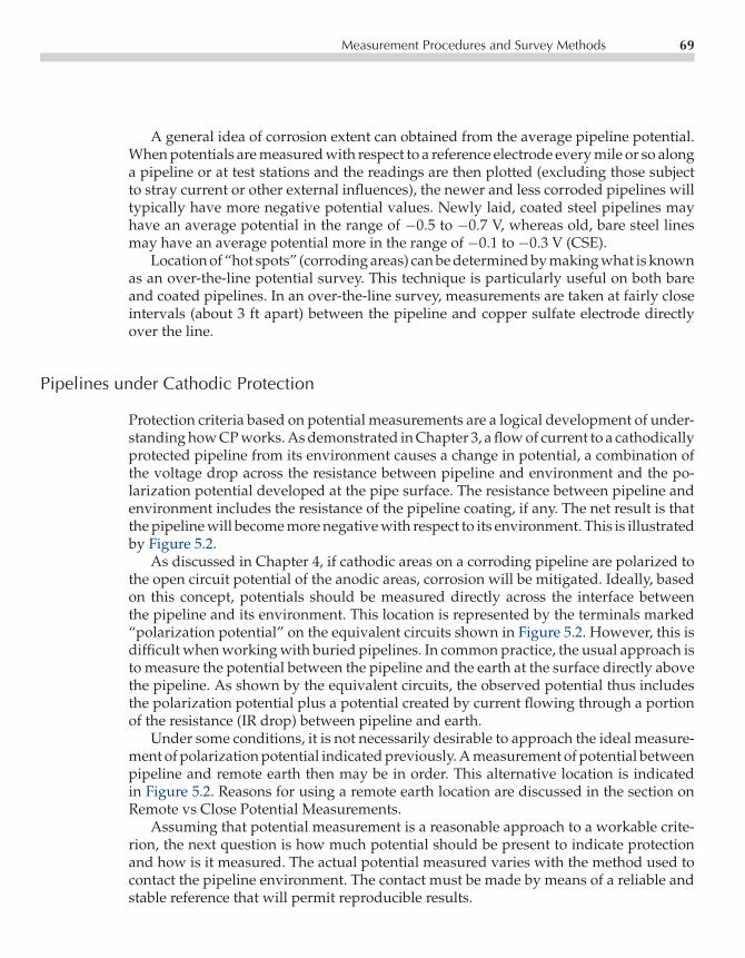
P1: LKC/FQA P2: FPVCE003-05 CE003-Peabody November 13, 2000 11:28 Char Count= 0
Measurement Procedures and Survey Methods 69
A general idea of corrosion extent can obtained from the average pipeline potential.When potentials are measured with respect to a reference electrode every mile or so alonga pipeline or at test stations and the readings are then plotted (excluding those subjectto stray current or other external influences), the newer and less corroded pipelines willtypically have more negative potential values. Newly laid, coated steel pipelines mayhave an average potential in the range of −0.5 to −0.7 V, whereas old, bare steel linesmay have an average potential more in the range of −0.1 to −0.3 V (CSE).
Location of “hot spots” (corroding areas) can be determined by making what is knownas an over-the-line potential survey. This technique is particularly useful on both bareand coated pipelines. In an over-the-line survey, measurements are taken at fairly closeintervals (about 3 ft apart) between the pipeline and copper sulfate electrode directlyover the line.
Pipelines under Cathodic Protection
Protection criteria based on potential measurements are a logical development of under-standing how CP works. As demonstrated in Chapter 3, a flow of current to a cathodicallyprotected pipeline from its environment causes a change in potential, a combination ofthe voltage drop across the resistance between pipeline and environment and the po-larization potential developed at the pipe surface. The resistance between pipeline andenvironment includes the resistance of the pipeline coating, if any. The net result is thatthe pipeline will become more negative with respect to its environment. This is illustratedby Figure 5.2.
As discussed in Chapter 4, if cathodic areas on a corroding pipeline are polarized tothe open circuit potential of the anodic areas, corrosion will be mitigated. Ideally, basedon this concept, potentials should be measured directly across the interface betweenthe pipeline and its environment. This location is represented by the terminals marked“polarization potential” on the equivalent circuits shown in Figure 5.2. However, this isdifficult when working with buried pipelines. In common practice, the usual approach isto measure the potential between the pipeline and the earth at the surface directly abovethe pipeline. As shown by the equivalent circuits, the observed potential thus includesthe polarization potential plus a potential created by current flowing through a portionof the resistance (IR drop) between pipeline and earth.
Under some conditions, it is not necessarily desirable to approach the ideal measure-ment of polarization potential indicated previously. A measurement of potential betweenpipeline and remote earth then may be in order. This alternative location is indicatedin Figure 5.2. Reasons for using a remote earth location are discussed in the section onRemote vs Close Potential Measurements.
Assuming that potential measurement is a reasonable approach to a workable crite-rion, the next question is how much potential should be present to indicate protectionand how is it measured. The actual potential measured varies with the method used tocontact the pipeline environment. The contact must be made by means of a reliable andstable reference that will permit reproducible results.

P1: LKC/FQA P2: FPVCE003-05 CE003-Peabody November 13, 2000 11:28 Char Count= 0
70 Survey Methods and Evaluation Techniques
POINT "C". CONTACT WITH"REMOTE" EARTH TO (−)TERMINAL OF VOLTMETER.
WHEN CONNECTED ASSHOWN, DIGITAL VOLTMETERWILL SHOW MORE NEGATIVEVALUES WHEN CATHODEPROTECTION SYSTEM ISENERGIZED AND FORCESCURRENT TO FLOW TO THEPIPE SURFACE
POINT "A"CONTACTWITH "CLOSE"EARTH
CATHODIC PROTECTIONPOWER SOURCE
GROUNDBEDANODE
EARTH
PIPE
COATING
POWERSOURCE
+ −+−
+ −
+ −+ −
+ −
PIPE
POLARIZEDPOTENTIAL
POINT "A"ON EARTHABOVE PIPE
COMBINATION OF ANODE-TO-EARTHRESISTANCE AND PIPE-TO-EARTHRESISTANCE WHICH IS LESS THANTHE SUM OF PIPE AND ANODERESISTANCES TO REMOTE EARTH.
EQUIVALENT CIRCUIT 1 EQUIVALENT CIRCUIT 2
PIPELINE WITHIN "AREA OFINFLUENCE" OF GROUND BED
GROUND BED ELECTRICALLYREMOTE FROM PIPELINE
RESISTANCEOF GROUNDBED ANODESTO REMOTEEARTH
POINT "C"
RESISTANCEBETWEENPIPELINEAND REMOTEEARTH
POWERSOURCE
POINT "B"CONTACT WITHPIPELINE
POINT"B"
POINT"B"
PIPE
POINT "A"ON EARTHABOVE PIPE
V
REMOTE EARTH
POLARIZATIONPOTENTIAL
Figure 5.2 Pipe-to-environment potential change with flow of cathodic protection current.

P1: LKC/FQA P2: FPVCE003-05 CE003-Peabody November 13, 2000 11:28 Char Count= 0
Measurement Procedures and Survey Methods 71
With the background developed above, a discussion of actual potentials can be un-dertaken. In Chapter 4, we discussed the concept that if cathodic areas on the pipelineare polarized to the open circuit potential of the anodic areas, macrocell corrosion willcease. As established by various investigators, the most highly anodic areas to be ex-pected on a steel pipeline in most soils and waters will have a potential of around−0.8 Vas measured with respect to a CSE contacting the environment immediately adjacent tothe anodic area. For usual potential measurements, it is not practical to excavate so thatthe electrode can be placed at pipe depth. The most common approach is to place theCSE at the ground surface directly above the pipeline. To allow for a drop in potential inthe soil between this point and the pipe, and to allow for some latitude in the potentialof the most highly anodic areas, the practical value of −0.85 V (CSE) has been adoptedas an indication of satisfactory protection. This criterion along with its applications andlimitations is discussed in detail in Chapter 4.
Remote vs Close Potential Measurements
Pipeline potential readings usually are referred to either “close” or “remote” electrodes.If neither is designated, “close” electrode will be meant in most cases.
Close Earth
A reading to close electrode usually means an observation made with the reference placedon the ground (or water) surface directly above the pipeline being studied. A reading toremote electrode means the reference is placed in earth that is electrically remote from thepipeline. Often, to permit reproducing similar conditions, the distance and direction willbe indicated, as “potential to remote CSE, 100 east” or similar notations. Applications ofboth types of reading are covered below.
Remote Earth
Under certain testing conditions, it may be desirable to know how far one has to gofrom a structure before the potential represents an electrically remote distance fromthe structure being evaluated. Examples are the area of influence around an impressedcurrent ground bed and the area affected by potential gradients around a cathodicallyprotected pipeline. This distance may be determined by a series of readings betweenthe structure being evaluated and a CSE moved away from the structure at specifiedintervals. When the data are plotted for a cathodically protected pipeline, it might appearas illustrated by Figure 5.3.
The plot taken at an impressed current ground bed would look similar except thatpotentials would increase in the positive direction instead of negative and the distanceto remote earth could be greater.

P1: LKC/FQA P2: FPVCE003-05 CE003-Peabody November 13, 2000 11:28 Char Count= 0
72 Survey Methods and Evaluation Techniques
−1.0
−0.9
−0.8
−0.7
−0.6
−0.5
0 50 100
Distance (feet) Between Pipeline and Copper Sulfate Electrode
Pot
entia
l of P
ipel
ine
to C
oppe
r S
ulfa
te E
lect
rode
(C
SE
)
Figure 5.3 Determination of remote earth.
It should be pointed out that the distance to remote earth will not necessarily be thesame at all points along a protected line nor will the distance to remote earth necessarilybe the same for all similarly sized impressed current ground beds at different locations.Both soil resistivity and soil structure have an effect. In high-resistivity soil areas, thedistance to remote tends to be greater. Probably the greatest effect causing extension ofthe distance to remote earth is observed at areas where pipelines or ground beds arein relatively shallow surface layers of earth overlying material of much higher resis-tivity (such as rock). In these instances, the current to the pipeline or from the groundbed tends to concentrate in the surface layer rather than come from or flow to the gen-eral earth mass. This substantially extends the distance from the structure to electricallyremote earth. Awareness of this effect, when working in such areas, is important inconsidering the possible interference effect of potential gradient fields on other struc-tures.
Over-The-Line Potential Surveys (Close Interval Surveys)
So why are different readings obtained when the reference is placed directly over theline? The readings are affected by corrosion current flowing to or from the pipe. Suchcurrents cause voltage drops in the soil in the immediate vicinity of the pipeline, which arereflected in the readings to a close electrode. Which readings then indicate unfavorableconditions?
In general, when interpreting over-the-line potential survey readings, for pipelineswithout CP the worst corrosion will be where the potential readings are the most nega-tive, and there will be little or no corrosion at the points of least negative readings.
To illustrate results that can be obtained with an over-the-line potential survey ona well-coated pipeline without CP, Figure 5.4 represents plotted data taken from an
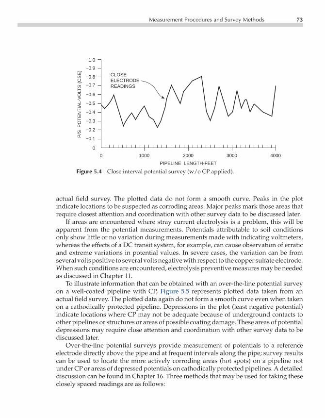
P1: LKC/FQA P2: FPVCE003-05 CE003-Peabody November 13, 2000 11:28 Char Count= 0
Measurement Procedures and Survey Methods 73
0 1000 2000 3000 4000
−1.0
−0.9
−0.8
−0.7
−0.6
−0.5
−0.4
−0.3
−0.2
−0.1
0
P/S
PO
TE
NT
IAL-
VO
LTS
(C
SE
)
PIPELINE LENGTH-FEET
CLOSEELECTRODEREADINGS
Figure 5.4 Close interval potential survey (w/o CP applied).
actual field survey. The plotted data do not form a smooth curve. Peaks in the plotindicate locations to be suspected as corroding areas. Major peaks mark those areas thatrequire closest attention and coordination with other survey data to be discussed later.
If areas are encountered where stray current electrolysis is a problem, this will beapparent from the potential measurements. Potentials attributable to soil conditionsonly show little or no variation during measurements made with indicating voltmeters,whereas the effects of a DC transit system, for example, can cause observation of erraticand extreme variations in potential values. In severe cases, the variation can be fromseveral volts positive to several volts negative with respect to the copper sulfate electrode.When such conditions are encountered, electrolysis preventive measures may be neededas discussed in Chapter 11.
To illustrate information that can be obtained with an over-the-line potential surveyon a well-coated pipeline with CP, Figure 5.5 represents plotted data taken from anactual field survey. The plotted data again do not form a smooth curve even when takenon a cathodically protected pipeline. Depressions in the plot (least negative potential)indicate locations where CP may not be adequate because of underground contacts toother pipelines or structures or areas of possible coating damage. These areas of potentialdepressions may require close attention and coordination with other survey data to bediscussed later.
Over-the-line potential surveys provide measurement of potentials to a referenceelectrode directly above the pipe and at frequent intervals along the pipe; survey resultscan be used to locate the more actively corroding areas (hot spots) on a pipeline notunder CP or areas of depressed potentials on cathodically protected pipelines. A detaileddiscussion can be found in Chapter 16. Three methods that may be used for taking theseclosely spaced readings are as follows:

P1: LKC/FQA P2: FPVCE003-05 CE003-Peabody November 13, 2000 11:28 Char Count= 0
74 Survey Methods and Evaluation Techniques
Distance
"On" potential
"Off" potential
Pip
e to
Soi
l Pot
entia
l (C
SE
) (−
mV
)
0+
00
1+
00
2+
00
3+
00
4+
00
5+
00
6+
00
7+
00
8+
00
−2500
−2000
−1500
−1000
−850
−500
−000
Figure 5.5 Over-the-line survey (with cathodic protection).
Method 1
The principle involved in the over-the-line survey is illustrated in Figure 5.6 which showsreadings taken on a continuous basis at 3- to 5-ft intervals along the pipeline. For an all-welded steel pipeline, there would be negligible voltage drop through the pipe betweenany two points tested (at the usual soil corrosion currents flowing in the pipe). Typically,
VSURVEYDIRECTION
VOLTMETERLOCATION
REFERENCEELECTRODESOVER PIPELINE
SPACING
PIPELINE
3-5 FEET
+ −
Figure 5.6 Over-the-line potential surveys (Method 1).

P1: LKC/FQA P2: FPVCE003-05 CE003-Peabody November 13, 2000 11:28 Char Count= 0
Measurement Procedures and Survey Methods 75
a measuring device, with light wire for continuous contact to the pipeline, is used witha data logger to capture data as the survey is being performed. The location of eachelectrode position is recorded with the observed potential. Different types of over-the-line survey equipment are discussed in Chapter 6.
In areas where traffic conditions, terrain features, or other obstructions do not in-terfere, long distances can be surveyed on either side of each pipeline connection. Thedistance is limited only by the length of test conductor available. The resistance of thelight-wire test lead should not be sufficient to cause noticeable error in potential measure-ments made with a suitable high-resistance voltmeter. This is true if spools of light wireconductors 3 to 5 miles long are maintained properly and have no high-resistance connec-tions. For example, 15,000 ft (3 miles) of no. 34 gage light wire would have a resistance ofapproximately 2,800 ohms. A high-impedence voltmeter or datalogger with a minimuminput impedence of 20× 106 ohms typically reduces any errors from the wire resistance.
Method 2
Another measurement technique involves the use of a pair of CSE in leapfrog fashion,as illustrated in Figure 5.7.
ELECTRODES AREPLACED ON SURFACEDIRECTLY ABOVE PIPE.
HIGH RESISTANCEVOLTMETER
REAR ELECTRODE "LEAP-FROGGED"TO FORWARD POSITION FOR EACHSUBSEQUENT READING.
SUBSEQUENTVOLTMETERLOCATIONS SURVEY
DIRECTION
FIRST READING SECOND READING ETC.
V V V
CUSO4ELECTRODE "A"POSITION 1
CUSO4ELECTRODE "B"POSITION 2
CUSO4ELECTRODE "A"POSITION 3
TEST POINT WIRE OR OTHERMETALLIC CONTACT WITHPIPELINE.
KNOWN SPACING
PIPELINE
+ − + − + −
Figure 5.7 Over-the-line potential surveys using two copper sulfate electrodes (Method 2).
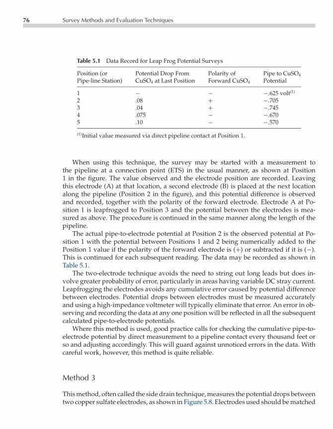
P1: LKC/FQA P2: FPVCE003-05 CE003-Peabody November 13, 2000 11:28 Char Count= 0
76 Survey Methods and Evaluation Techniques
Table 5.1 Data Record for Leap Frog Potential Surveys
Position (or Potential Drop From Polarity of Pipe to CuSO4
Pipe-line Station) CuSO4 at Last Position Forward CuSO4 Potential
1 − − −.625 volt(1)
2 .08 + −.7053 .04 + −.7454 .075 − −.6705 .10 − −.570
(1)Initial value measured via direct pipeline contact at Position 1.
When using this technique, the survey may be started with a measurement tothe pipeline at a connection point (ETS) in the usual manner, as shown at Position1 in the figure. The value observed and the electrode position are recorded. Leavingthis electrode (A) at that location, a second electrode (B) is placed at the next locationalong the pipeline (Position 2 in the figure), and this potential difference is observedand recorded, together with the polarity of the forward electrode. Electrode A at Po-sition 1 is leapfrogged to Position 3 and the potential between the electrodes is mea-sured as above. The procedure is continued in the same manner along the length of thepipeline.
The actual pipe-to-electrode potential at Position 2 is the observed potential at Po-sition 1 with the potential between Positions 1 and 2 being numerically added to thePosition 1 value if the polarity of the forward electrode is (+) or subtracted if it is (−).This is continued for each subsequent reading. The data may be recorded as shown inTable 5.1.
The two-electrode technique avoids the need to string out long leads but does in-volve greater probability of error, particularly in areas having variable DC stray current.Leapfrogging the electrodes avoids any cumulative error caused by potential differencebetween electrodes. Potential drops between electrodes must be measured accuratelyand using a high-impedance voltmeter will typically eliminate that error. An error in ob-serving and recording the data at any one position will be reflected in all the subsequentcalculated pipe-to-electrode potentials.
Where this method is used, good practice calls for checking the cumulative pipe-to-electrode potential by direct measurement to a pipeline contact every thousand feet orso and adjusting accordingly. This will guard against unnoticed errors in the data. Withcareful work, however, this method is quite reliable.
Method 3
This method, often called the side drain technique, measures the potential drops betweentwo copper sulfate electrodes, as shown in Figure 5.8. Electrodes used should be matched

P1: LKC/FQA P2: FPVCE003-05 CE003-Peabody November 13, 2000 11:28 Char Count= 0
Measurement Procedures and Survey Methods 77
Figure 5.8 Over-the line (Method 3).
(not more than 5 mV difference in electrode potential). Measurements are made oneach side of a unprotected pipeline, typically in areas in question, to identify areas ofcurrent flow onto and off the pipeline. In Fig 5.8 positive voltage reading would indicatecurrent flow to the pipe. A negative voltage reading would indicate current flow off thepipeline.
This technique is not widely used because it is time-consuming. Direct contact poten-tial measurements as described in Method 1 are easier than the other methods described.Methods 2 and 3 are typically used to qualify specific areas of concern identified usingMethod 1 survey techniques.
Line Current Measurements
Measurement of pipeline current by the resistance drop method is useful in pipelinesurvey work. It is also useful in determining the distribution of current along a cathodi-cally protected pipeline and for other applications such as stray current. The proceduresoutlined typically use permanent test points to contact the pipe.
Permanent Two-Wire Test Points
Where the two-wire test points spanning a known length of pipe are available, cur-rents may be measured by determining the potential drop across the span, selecting thepipe resistance from tables, and calculating the current using Ohm’s law. The generalarrangement is shown in Figure 5.9.
The procedure may be performed as follows:
1. Measure the circuit resistance of the test leads and pipe span by passing known batterycurrent through the circuit and measuring the resulting voltage drop across the testpoint terminals. Calculate resistance in ohms by Ohm’s law: R (resistance)= V (volts)divided by I (amperes). If the resistance obtained is higher than reasonable for thesize and length of test wires, defective leads may be suspected.

P1: LKC/FQA P2: FPVCE003-05 CE003-Peabody November 13, 2000 11:28 Char Count= 0
78 Survey Methods and Evaluation Techniques
A
MV
CLOSE SWITCH FORSTEP 1 ONLY
BATTERYFOR STEP 1ONLY
TEST POINTTERMINALS
PIPE SPAN IN FEET
PIPE SIZE AND WALLTHICKNESS OR WEIGHTPER FOOT MUST BEKNOWN WIRES MUST BE
COLOR CODED
PIPELINE
AMMETER
VOLTMETER
+−
+−
Figure 5.9 Current measurement, 2-wire test point.
2. Measure the voltage drop across the test point terminals caused by the normal currentflowing in the pipeline. Usually this will be millivolts or microvolts. Instrument resis-tance must be known and correction made for the external circuit (measured in Step 1).Note the polarity of the meter connection to the test point terminals and indicate thedirection of current flow (+ to −) along the pipeline.
3. Using pipeline resistance tables, determine the resistance of the pipeline span.4. Calculate the pipeline current flow by Ohm’s law. Current in milliamperes= corrected
millivolt drop (from Step 2) divided by pipe span resistance in ohms.
Table 5.2 may be used as a general guide to pipeline resistance. Resistivity values forsteel typically range between 15 and 23 µÄ-cm, depending on the composition of thesteel. The average value is ∼18 µÄ-cm.
Sample determination of current flow on a 200-ft span of 30-in-diameter pipe weigh-ing 118.7 lb/ft (pipeline runs east and west) requires the following measurements andcalculations:
Step 1. (Battery current= 1.2 A; voltage drop= 0.108 V; circuit resistance= 0.108/1.2=0.09 ohm.
Step 2. Potential drop at test point terminals = 0.16 mV; the west terminal is (+).
Step 3. Resistance of pipeline span (from Table 5.2)= 2.44×10−6×200 = 0.49 milliohm.
Step 4. Current = 0.17 mV/0.49 milliohm = 346 mA; flow is from west to east.

P1: LKC/FQA P2: FPVCE003-05 CE003-Peabody November 13, 2000 11:28 Char Count= 0
Measurement Procedures and Survey Methods 79
Table 5.2 Steel Pipe Resistance1
Pipe Size, Outside Wall Thickness, Weight Per Resistance of One Foot2 inInches Diameter, Inches Inches Foot, Pounds Ohms×10−6 (Millionths of an Ohm)
2 2.375 0.154 3.65 79.24 4.5 0.237 10.8 26.86 6.625 0.280 19.0 15.28 8.625 0.322 28.6 10.1
10 10.75 0.365 40.5 7.1312 12.75 0.375 49.6 5.8214 14.00 0.375 54.6 5.2916 16.00 0.375 62.6 4.6118 18.00 0.375 70.6 4.0920 20.00 0.375 78.6 3.6822 22.00 0.375 86.6 3.3424 24.00 0.375 94.6 3.0626 26.00 0.375 102.6 2.8228 28.00 0.375 110.6 2.6230 30.00 0.375 118.7 2.4432 32.00 0.375 126.6 2.2834 34.00 0.375 134.6 2.1536 36.00 0.375 142.6 2.03
1Based on steel density of 489 pounds per cubic foot and steel resistivity of 18 microhm-cm as stated in text.2 R = 16.061×Resistivity in Microhm-cm
Weight per foot = resistance of one foot of pipe in microhms.
Permanent Four-Wire Test Points
Pipelines having four-wire test points with two color-coded wires at each end of a current-measuring span are best equipped for accurate measurements of pipeline current becauseeach such span can be calibrated accurately. This avoids errors in length of pipe spanand pipe resistance that may occur when the two-wire test point is used. The generalarrangement for a pipeline current measurement is shown in Figure 5.10.
The test procedure is as follows:
1. Measure the circuit resistance in the current measuring span (between terminals 2 and3) by using Step 1 for the two-wire test point procedure.
2. Calibrate the span by passing a known amount of battery current between the outsideleads (terminals 1 and 4) and measure the change in potential drop across the cur-rent measuring span (terminals 2 and 3). Divide the current flow in amperes by thepotential drop in millivolts to express the calibration factor in amperes per millivolt.Normally, when the pipeline operating temperature is stable, the calibration factorremains constant and does not need to be recalibrated. However, on pipelines wherethe temperature of the pipe changes considerably (with accompanying changes inresistance), more frequent calibration may be necessary.

P1: LKC/FQA P2: FPVCE003-05 CE003-Peabody November 13, 2000 11:28 Char Count= 0
80 Survey Methods and Evaluation Techniques
CURRENT MEASURING SPAN
FIVE PIPE DIAMETERS SUGGESTED
COLOR CODEDTEST POINT LEADS
1 2 3 4
STEP 1 ONLY
STEP 2 ONLY
TEST POINTTERMINALS
BATTERY A
MV
CLOSE SWITCH FORSTEPS 1 AND 2 ONLY
PIPELINE
AMMETER
VOLTMETER
+−
+−
Figure 5.10 Current measurement, 4-wire test point.
3. Measure the potential drop in millivolts across the current-measuring span (termi-nals 2 and 3) caused by the normal pipeline current. Calculate the current flow bymultiplying the measured potential drop by the calibration factor determined in Step2. Note the direction of current flow.
Sample determination of current flow in the same pipeline section used for the exam-ple on two-wire test point current determination requires the following measurementsand calculations:
Step 1. Circuit resistance between terminals 2 and 3 measured as 0.09 ohm.
Step 2. Ten amperes of battery current passed between terminals 1 and 4. Correctedpotential drop, current on= 5.08 mV. Corrected potential drop, current off= 0.17mV. Change in potential drop (1V) = 4.91 mV. Calibration factor = 10 A/4.91mV = 2.04 A/mV.

P1: LKC/FQA P2: FPVCE003-05 CE003-Peabody November 13, 2000 11:28 Char Count= 0
Measurement Procedures and Survey Methods 81
AMMETER VOLTMETER
ADJUSTABLEBATTERYVOLTAGE SUPPLY
FOUR-WIRE TESTPOINT TERMINALS
COLOR CODED LEADS
DIRECTION OF CURRENT FLOWTO BE MEASURED
A
MV
(− ) (+ )
(− ) (+ )
(+ )
PIPELINE
Figure 5.11 Null ammeter circuit.
Step 3. Potential drop across current-measuring span (terminals 2 and 3)= 0.17 mV (cor-rected) with west end terminal (+). Pipeline current = 0.17 mV× 2.04 A/mV=0.346 A (346 mA); flow is from west to east.
An alternative method for measuring line current is to use a null ampere test cir-cuit arrangement based on procedures described by Werner.6 The circuit, illustrated byFigure 5.11, is used with four-wire test points. With a high-impedance voltmeter con-nected between the inner pair of wires, current from the battery flows between the outerpair of wires in opposition to the measured current flowing in the pipe. As the oppositioncurrent is increased, the voltage measured will move towards zero. When the voltagereading is at or very near zero, the subsequent opposition current measured on the am-meter represents the magnitude of current flow in the pipeline span under consideration.Remember the measured opposition current is flowing in the opposite direction of theactual current flow on the pipeline, so be sure to document the actual direction of pipelinecurrent flow (the opposite of that of the opposition current).
Probe Rods
Where necessary, pipeline current may be measured by obtaining the potential dropacross a pipe span of measured length. The pipe may be contacted at each end of the spanby using pipe-contacting probe rods as described earlier. Otherwise, the test arrangement

P1: LKC/FQA P2: FPVCE003-05 CE003-Peabody November 13, 2000 11:28 Char Count= 0
82 Survey Methods and Evaluation Techniques
is generally similar to that illustrated in Figure 5.9. There are, however, several additionalsteps (to ensure accuracy) to those outlined for the two-wire test point procedure.
The set-up and test procedure may be performed as follows:
Step 1. Locate the pipeline with a pipe locator so that probe rods may be worked intothe ground squarely above the pipe.
Step 2. Measure and mark off the current measuring span (such as 100 ft) to an accuracyof ±1 in.
Step 3. Insert the probe rods, working them down to a solid contact with the pipe steel.The rods must be kept vertical so that the span length will not deviate from themeasured value.
Step 4. The two leads used to connect the measuring instrument to the probe rods shouldbe connected together first, so the series resistance of the two leads can be mea-sured and the value noted.
Step 5. Connect the two leads to the probe rods and measure the circuit resistance, whichincludes the test lead resistance and that of the pipe span. This value shouldbe the same, for all practical purposes, as the resistance of the test leads only(measured in Step 4). This is because the resistance of an electrically continuouspipe span is so low compared with that of the test wires that the difference willnot be detectable by the usual test procedures (except for long spans of verysmall pipe). If the resistance is measurably higher, it would be assumed thatgood contact between probe rods and pipe has not been attained. Work the rodsagainst the pipe until the circuit remains stable. (If the circuit resistance doesnot drop to the desired value with solid contacts between rods and pipe, it is anindication of a possible extraneous resistance in the pipe span, such as a pipefitting or mechanical coupling. In this event, current flow cannot be measuredaccurately and it will be necessary to move the probe rods to another point wherethey will span solid pipe.)
Step 6. Measure the millivolt drop between the two probe rods and correct the readingfor the effect of the external circuit resistance. Note the polarity to determinedirection of current flow.
Step 7. Repeat the circuit resistance measurement of Step 5 to be sure that the circuit hasremained stable while the test was being made. If not, repeat the procedure.
Step 8. Determine pipe span resistance from Table 5.2 and calculate the current flowby Ohm’s law, following the procedure established for two-wire permanent testpoints.
Line Current Survey Evaluation Methods
If corrosion is taking place on a pipeline, there will be current flow to the line at somepoints and current flow away from the line at others. For small local cells, often termed

P1: LKC/FQA P2: FPVCE003-05 CE003-Peabody November 13, 2000 11:28 Char Count= 0
Measurement Procedures and Survey Methods 83
“long line,” the current may follow the pipe for hundreds or thousands of feet. It is theselong-line currents that can be detected in a line current survey.
Because the pipe itself has some resistance to the flow of electric current, there will bea voltage drop in the pipe if current is flowing through this pipe resistance. The voltagedrops are usually very small but can be determined by using suitable instrumentation(discussed in Chapter 6). The resistance per foot of steel pipe is not great and becomesprogressively smaller as the pipe size and weight per foot increases. Many pipelinecompanies install permanent test point installations with wires of a known span length,for example, 100 ft. To see how sensitive such a span would be to small values of pipelinecurrent, consider two examples:
1. If the pipeline is an 8-in-diameter line with 0.322-in-thick wall weighs 28.6 lb/ft andis made of 5LX32 steel, the resistance across a 100-ft span would be 9.75×10⁻⁴ ohms.If the available test instrument is sensitive to a potential as small as 0.02 mV, a currentof only 20.5 mA flowing through the span resistance would cause this minimumdeflection.
2. A 30-in-diameter line with 0.375-in-thick walls weighs 118.7 lb/ft (also of 5LX32 steel)will have a 100-ft span resistance of ∼2.36 × 10⁻⁴ ohms. With this lower resistancespan, a current flow of 84.7 mA through the pipeline will be required to give theassumed minimum deflection of 0.02 mV. Obviously, a given test span length is muchless sensitive on large-diameter pipe than on small lines. Using longer span lengths onlarge pipes (that is increasing the span resistance) will result in increased sensitivity.
On lines without permanently installed test spans, contact bars may be used to es-tablish a span for test purposes. This must be done carefully to avoid error as discussedearlier. This procedure would be necessary, however, to make closely spaced line currentmeasurements (at 500- or 1000-ft intervals, for example) during a line current survey ona bare line.
At each point of measurement in a line current survey, the voltage drop is observedand recorded, together with the polarity of instrument connections to indicate the di-rection of current flow (plus to minus). Knowing the span resistance of the pipe beingsurveyed, one may convert the voltage drops to equivalent current flow by applicationof Ohm’s law (voltage drop in millivolts/span resistance in ohms= current flow in mil-liamperes). The values of current together with the direction of flow then may be plottedvs line length. The results might be generally similar to the plot shown by Figure 5.12.
As illustrated, at one area the current flows from both directions toward a particularpoint on the line. This must be a point of current discharge and, unless the current isbeing drained off by a metal contact such as through another structure, corrosion maybe expected in that area.
Line current surveys in most cases will be more meaningful for bare lines than forwell-coated lines. On coated pipe, current can enter or leave the pipe only through breaksor pinholes in the coating. With current concentrated at these coating defects, currentdensity in terms of milliamperes per square foot of exposed steel usually is greater thanon bare pipe. This means that the degree of attack will be greater at coating defects inanodic areas on coated pipe with a greater rate of penetration than would be the case

P1: LKC/FQA P2: FPVCE003-05 CE003-Peabody November 13, 2000 11:28 Char Count= 0
84 Survey Methods and Evaluation Techniques
0 1000 2000 3000 4000
400
350
300
250
200
150
100
50
0
PIPELINE LENGTH-FEET
PIP
ELI
NE
CU
RR
EN
T-M
ILLI
AM
PS
Figure 5.12 Line current survey.
with bare pipe under similar soil conditions. Nevertheless, the total long-line currentflow on the coated pipe between anodic and cathodic areas would be much less than onbare pipe (again, under similar soil conditions) because, with reasonably good coating,all but a very small percentage of the pipeline steel is insulated from the surrounding soil.
There are several possibilities of error in making line current surveys. Care must betaken when using probe bars to contact the pipe as mentioned earlier. Unless actualresistance is measured for each test span, changes in pipe size or wall thickness (thatis, differences from what may be normal for the line being surveyed) can result in theactual span resistance being substantially different from that calculated from the normalpipe dimensions. Likewise, unless the span resistance is measured, the presence of anunknown mechanical pipe coupling in the test span could introduce enough resistanceto make results completely erroneous. Permanently installed test spans are usually putin at the time of pipeline construction, using span length and color-coded wiring inaccordance with an established specification. Errors in color coding may result in thecurrent flow being indicated in the wrong direction.
When planning test point installations for new pipeline systems (or when installingthem on an existing system), it is good practice to provide current-measuring test spanswith two separate wires connected to the pipeline at each end of the span. This permitsmeasuring the actual span resistance, as described earlier.
Soil Resistivity Survey
This indication of a tendency for current to flow becomes more important if somethingis known about the soil resistivity. High-resistivity soils may offer so much resistance

P1: LKC/FQA P2: FPVCE003-05 CE003-Peabody November 13, 2000 11:28 Char Count= 0
Measurement Procedures and Survey Methods 85
2,000
00 1000 2000 3000 4000
4,000
6,000
8,000
10,000
100,000
PIPELINE LENGTH-FEET
SO
IL R
ES
IST
IVIT
YO
HM
-CE
NT
IME
TE
RS
Figure 5.13 Soil resistivity survey.
to current flow that conditions are not as severe as the plotted potential data mightlead one to believe. Conversely, severe potential peaks coupled with a relatively lowresistivity environment may mean a truly serious condition. Frequent soil resistivitydeterminations are important when making a detailed survey on a pipe line. In additionto being a valuable aid when interpreting the severity of corrosive areas, a soil resistivityprofile is extremely helpful in the later selection of sites for CP installations. Figure 5.13is a plot of the soil resistivity measurements taken along the same section of pipelineused as a basis for the plots shown in Figures 5.4 and 5.12.
Data plotted in the figure represent average soil resistivity to approximate pipe depth.In this example, a very wide range of soil resistivity is represented. Other cases would notnecessarily have such a large difference between maximum and minimum resistivitiesalong a similar length of line.
Along well-coated pipelines, measurements of soil resistivity can be of great assis-tance in the later selection of CP installations. This may be particularly true to identifyareas where soils of suitable low resistivity for such installations.
Instruments used for measuring soil resistivity by the four-pin method are describedin Chapter 6. Certain precautions to be observed in using the method are given below,together with suggestions for planning soil resistivity measurements.
In the example shown, resistivity of the soil was measured at∼100-ft intervals alongthe proposed alignment. Soil resistivity measurements were conducted by the Wennerfour-pin method, utilizing a soil resistance meter (see Chapter 6). The Wenner methodrequires the use of four metal probes or electrodes, driven into the ground along a straightline, equidistant from each other, as shown in Figure 5.14. An alternating current fromthe soil resistance meter causes current to flow through the soil, between pins C1 andC2. The voltage or potential is then measured between pins P1 and P2. The meter then

P1: LKC/FQA P2: FPVCE003-05 CE003-Peabody November 13, 2000 11:28 Char Count= 0
86 Survey Methods and Evaluation Techniques
a a a
P1
PINC1
PINP1
PINP2
PINC2
C1
P2
C2
Soil Resistance Meter
Figure 5.14 Soil resistivity test set-up (Wenner four pin method).
registers a resistance reading. Resistivity of the soil is then computed from the instrumentreading, according to the following formula:
ρ = 2πAR
where ρ = soil resistivity (ohm-centimeters)
A= distance between probes (centimeters)
R = soil resistance (ohms) instrument readingπ = 3.1416
The resistivity values obtained represent the average resistivity of the soil to a depthequal to the pin spacing. Resistance measurements are typically performed to a depthequal to that of the pipeline being evaluated. Typical probe spacings are in incrementsof 2.5 ft (76.2 cm).
If the line of soil pins used when making four-pin resistivity measurements is closelyparallel to a bare underground pipeline or other metallic structure, the presence of thebare metal may cause the indicated soil resistivity values to be lower than it actuallyis. Because a portion of the test current will flow along the metallic structure ratherthan through the soil, measurements along a line closely parallel to pipelines should beavoided. When making soil resistivity measurements along a pipeline, it is good practiceto place the line of the pins perpendicular to the pipeline with the nearest pin at least15 ft from the pipe—further, if space permits.

P1: LKC/FQA P2: FPVCE003-05 CE003-Peabody November 13, 2000 11:28 Char Count= 0
Measurement Procedures and Survey Methods 87
Table 5.3 Format for Recording Soil Resistivity Measurements
Nominal Pin Resistivity inTest Location Spacing, Feet Ohms Factor Ohm-cm
No. 1Pipeline Station 2.5 4.40 500 22001000+ 00. Nearest 5 2.05 1,000 2050pin 100 ft west of pipe. 7.5 1.26 1,500 1890Line of tests perpendicular 10 0.96 2,000 1920to pipe. Clay Moist 12.5 0.78 2,500 1950
15 0.62 3,000 186050 0.17 10,000 1700
No. 2Station 1001+ 00. 2.5 1.30 500 650Nearest pin 200 ft 5 0.60 1,000 600east of pipe. Line of 7.5 0.45 1,500 675tests parallel to pipe. 10 0.36 2,000 720Edge of swamp. Wet 12.5 0.34 2,500 850
15 0.33 3,000 99025 0.34 5,000 1700
Soil resistivity data taken by the four-pin method should be recorded in tabular formfor convenience in calculating resistivities and evaluating results obtained. The tabulararrangement may be as shown in Table 5.3. Where many soil resistivity measurementsare to be made, field time will be saved by using printed forms arranged for entering thenecessary data.
With experience, much can be learned about the soil structure by inspecting seriesof readings to increasing depths. The recorded values from four-pin resistivity measure-ments can be misleading unless it is remembered that the soil resistivity encounteredwith each additional depth increment is averaged, in the test, with that of all the soil inthe layers above. The indicated resistivity to a depth equal to any given pipe spacing isa weighted average of the soils from the surface to that depth. Trends can be illustratedbest by inspecting the sets of soil resistivity readings in Table 5.4.
Soil resistivity is an electrical characteristic of the soil/groundwater which affectsthe ability of corrosion currents to flow through the electrolyte (soil/groundwater).Resistivity is a function of soil moisture and the concentrations of ionic soluble saltsand is considered to be most comprehensive indicator of a soil’s corrosivity. Typically,the lower the resistivity, the higher will be the corrosivity.
Table 5.5 correlates resistivity values with degree of corrosivity. The interpretationof soil resistivity varies among corrosion engineers. However, this table is a generallyaccepted guide.
The first set of data in Table 5.4, Set A, represents a uniform soil conditions. Theaverage of the readings shown (∼960 ohm-cm) represents the effective resistivity
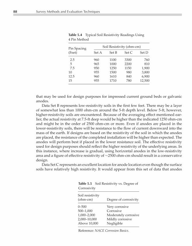
P1: LKC/FQA P2: FPVCE003-05 CE003-Peabody November 13, 2000 11:28 Char Count= 0
88 Survey Methods and Evaluation Techniques
Table 5.4 Typical Soil Resistivity Readings Using4 Pin Method
Soil Resistivity (ohm-cm)Pin Spacing(Feet) Set A Set B Set C Set D
2.5 960 1100 3300 7605 965 1000 2200 8107.5 950 1250 1150 1,900
10 955 1500 980 3,80012.5 960 1610 840 6,90015 955 1710 780 12,500
that may be used for design purposes for impressed current ground beds or galvanicanodes.
Data Set B represents low-resistivity soils in the first few feet. There may be a layerof somewhat less than 1000 ohm-cm around the 5-ft depth level. Below 5-ft, however,higher-resistivity soils are encountered. Because of the averaging effect mentioned ear-lier, the actual resistivity at 7.5-ft deep would be higher than the indicated 1250 ohm-cmand might be in the order of 2500 ohm-cm or more. Even if anodes are placed in thelower-resistivity soils, there will be resistance to the flow of current downward into themass of the earth. If designs are based on the resistivity of the soil in which the anodesare placed, the resistance of the completed installation will be higher than expected. Theanodes will perform best if placed in the lower resistance soil. The effective resistivityused for design purposes should reflect the higher resistivity of the underlying areas. Inthis instance, where increase is gradual, using horizontal anodes in the low-resistivityarea and a figure of effective resistivity of∼2500 ohm-cm should result in a conservativedesign.
Data Set C represents an excellent location for anode location even though the surfacesoils have relatively high resistivity. It would appear from this set of data that anodes
Table 5.5 Soil Resistivity vs. Degree ofCorrosivity
Soil resistivity(ohm-cm) Degree of corrosivity
0–500 Very corrosive500–1,000 Corrosive1,000–2,000 Moderately corrosive2,000–10,000 Mildly corrosiveAbove 10,000 Negligible
Reference: NACE Corrosion Basics.

P1: LKC/FQA P2: FPVCE003-05 CE003-Peabody November 13, 2000 11:28 Char Count= 0
Measurement Procedures and Survey Methods 89
located>5-ft deep, would be in low-resistivity soil of∼800 ohm-cm, such a figure beingconservative for design purposes. A lowering resistivity trend with depth, as illustratedby this set of data, can be relied upon to give excellent ground bed performance.
Data Set D is the least favorable of these sample sets of data. Low-resistivity soil ispresent at the surface but the upward trend of resistivity with depth is immediate andrapid. At the 7.5-ft depth, for example, the resistivity could be tens of thousands of ohm-centimeters. One such situation could occur where a shallow swampy area overlies solidrock. Current discharged from anodes installed at such a location will be forced to flow forrelatively long distances close to the surface before electrically remote earth is reached. Asa result, potential gradients forming the area of influence around an impressed currentground bed can extend much farther than those surrounding a similarly sized groundbed operating at the same voltage in more favorable locations such as those representedby data Sets A and C.
One mathematical procedure, known as the Barnes method, is based on calculatingthe resistivity of the soil in each incremental layer of soil. This is done by using thedata from the four-pin soil resistivity test but extending the calculations by determiningthe conductivity of each incremental layer and converting this conductivity to resistivity.Applying the procedure to the Set B soil resistivities (Table 5.6) provides a demonstrationof the method.
The Barnes method of analysis is not infallible because its accuracy requires soillayers to be of uniform thickness and parallel to the surface. In cases, where this is true,each added layer of earth must increase the total conductivity from the surface to thebottom of the added layer, no matter what the resistivity of the added layer may be. If, as
Table 5.6 Calculation of Soil Resistivity by Layers
4-PIN DATA, SET B1 BARNES PROCEDURE
Layer Resistivity
Spacing R1 Resistivity Mhos2 Mhos3 R2 Ohms and LayerFeet Ohms Factor Ohm-Cm 1/R1 11/R1 1/1 1/R1 Factor4 Ohm-cm Depth, Feet
2.5 2.2 500 1100 0.455 — — — 1100 0–2.55.0 1.0 1000 1000 1.0 .545 1.84 500 920 2.5–5.07.5 0.833 1500 1250 1.2 .20 5.0 500 2500 5.0–7.5
10.0 0.75 2000 1500 1.33 .13 7.7 500 3850 7.5–1012.5 0.645 2500 1610 1.55 .22 4.55 500 2275 10–12.515.0 0.57 3000 1710 1.75 .20 5.0 500 2500 12.5–15
1From Table 5.42This is the conductivity in mhos (reciprocal of resistance) to the indicated depth.3This is the increase in conductivity caused by the added layer of earth.4The factor used here is for nominal 2.5 foot layer increments. If other layer thickness are used, the factor mustbe changed accordingly (191.5 × layer thickness in feet).

P1: LKC/FQA P2: FPVCE003-05 CE003-Peabody November 13, 2000 11:28 Char Count= 0
90 Survey Methods and Evaluation Techniques
in the sample calculations above, the conductivity (the column headed 1/R1) continuesto increase with depth, conditions appear to approach the ideal closely enough to makethe method usable. Decreases in the conductivity at any point in a series are an indicationthat soil layers are too distorted to permit use of the method for analysis of data at thatdepth. For example, if the Barnes method procedure is applied to soil data Set D, resultscannot be calculated by this method below the 5-ft level. One inference from this typeof data is that the low resistivities observed near the surface indicate the presence ofa limited pocket of favorable soil in an area of soil having predominantly very highresistivity.
In some areas, experience will show that soil resistivities may change markedly withinshort distances. A sufficient number of four-pin tests should be made in a ground bedconstruction area, for example, to be sure that the best soil conditions have been located.For ground beds of considerable length (as may be the case with impressed currentbeds), four-pin tests should be taken at intervals along the route of the proposed lineof ground bed anodes. If driven rod tests or borings are made to assist in arriving atan effective soil resistivity for design purposes, such tests should be made in enoughlocations to ascertain the variation in effective soil resistivity along the proposed line ofanodes.
Soil Chemical Analysis
If soil samples are not measured “on location” but are collected for later measurement,they should be kept in air-tight containers to preserve the normal moisture content. Insome instances, abnormally dry surface soils may be moistened with distilled water toobtain their resistivity under wet conditions.
A wide variety of soluble salts are typically found in soils. Two soils having thesame resistivity may have significantly different corrosion characteristics, dependingon the specific ions available. The major constituents that accelerate corrosion are chlo-rides, sulfates, and the acidity (pH) of the soil. Calcium and magnesium tend to forminsoluble oxide and bicarbonate precipitates in basic environments, which can create aprotective layer over the metal surface and reduce the corrosion. In contrast, the chlorideion tends to break down otherwise protective surface deposits and can result in corro-sion and corrosion pitting of buried metallic structures. Bicarbonates are not typicallydetrimental to buried metallic. However, high concentrations of bicarbonates found insoils/groundwater tend to lower the resistivity without the resulting increase in corro-sion activity.
Soil samples should be taken at the depth of the pipeline in areas where soil resistivitydata may indicate corrosive conditions. Samples should be sent to a qualified laboratoryto perform the analysis in accordance with standard practices.
Table 5.7 correlates the effect of chlorides, sulfates, and pH on the corrosion of buriedsteel or concrete structures. Acidity, as indicated by the pH value, is another aggressivefactor of soil/groundwater. The lower the pH (the more acidic the environment), thegreater the corrosivity with respect to buried metallic structures. As pH increases to >7

P1: LKC/FQA P2: FPVCE003-05 CE003-Peabody November 13, 2000 11:28 Char Count= 0
Measurement Procedures and Survey Methods 91
Table 5.7 Effect of Chlorides, Sulfates, and pHon Corrosion of Buried Steel Pipelines
Concentration (ppm) Degree of corrositivity
Chloride1
>5,000 Severe1,500–5,000 Considerable500–1,500 Corrosive<500 Threshold
Sulfate1
>10,000 Severe1,500–10,000 Considerable150–1,500 Positive0–150 Negligible
pH2
<5.5 Severe5.5–6.5 Moderate6.5–7.5 Neutral>7.5 None (alkaline)
1Reference: ACI-318, Building Code Requirements forReinforced Concrete (American Concrete Institute,1999).2Reference: M. Romanoff, Underground Corrosion,1957.
(the neutral value), conditions become increasingly more alkaline and less corrosive toburied steel structures.
In many areas, soils encountered along a pipeline route will be approximately neutral(pH 7). There may, however, be locations where unusual environmental conditions exist,either alkaline (pH values >7) or acid (pH values <7).
Alkaline conditions do not pose any serious difficulty to steel pipelines because suchan environment is not aggressive toward steel. Strongly alkaline conditions can be detri-mental to aluminum piping, however. Under some conditions, use of CP may not beable to prevent alkaline attack on aluminum.
Acid conditions around the pipe have the general effect of making it much moredifficult to polarize the line to protective potentials (the acid acts as a depolarizing agent)when CP is applied. This increases the current requirements in the area.
Clearly, during a corrosion survey, it would be of value to check the soil pH inareas where there is a possibility of unusual chemical conditions. The results couldhave considerable effect on the locations selected for CP rectifiers or galvanic anodes.A particularly acid soil condition, for example, would indicate the need for a relativelyhigh current density to maintain CP. This could in turn make it desirable to locate CPinstallations at or near the area of high current requirement.

P1: LKC/FQA P2: FPVCE003-05 CE003-Peabody November 13, 2000 11:28 Char Count= 0
92 Survey Methods and Evaluation Techniques
CURRENT REQUIREMENT TESTING FOR CATHODIC PROTECTION
Bare Lines
Current Applied Method
The most widely used method for current requirement testing of a pipeline is representedbelow in Figure 5.15. Basically, direct current is forced to flow from a temporary groundconnection to the pipeline section being studied, and determining how much currentwill be needed to protect that section.
The output of the current source shown in the figure may be adjusted until protectivepotentials are attained at the ends of the section to be protected. When working withbare line, the current should be allowed to flow steadily, which will permit the line topolarize to some degree, depending on the duration of the test. Full polarization on a bareline may take weeks to achieve; if, however, during the test, the increase in protectivepotential is plotted versus time at a fixed current output, the curve can be extendedto give a rough approximation of the potentials that would be obtained with completepolarization. Current flowing into the protected section from the pipeline on either sidemay be measured by the voltage drop across a known pipe span as described previously.These two values may then be subtracted from the total current to obtain the net flowinto the protected section. Getting the net current in this manner is significant if, whenmaking permanent CP installations, there will be CP units in adjacent areas that would
V
+ −
V
+ −
V
+ −
V
+ −
V
+ −
TEMPORARYGROUND CONNECTION
1.7 A (CALCULATED)
MV+ − A
+−
−+
MV− +
SOURCEOF D-C
AMMETER59.0 AMPSBARE
PIPELINE
1.2 A (CALCULATED)
−0.85 V −1.02 V −3.20 V −1.10 V −0.85
VOLTMETER
Figure 5.15 Current requirements for CP.

P1: LKC/FQA P2: FPVCE003-05 CE003-Peabody November 13, 2000 11:28 Char Count= 0
Current Requirement Testing for Cathodic Protection 93
reduce or eliminate the current flow from remote areas into the area being tested asdescribed.
Current requirement tests of the type described do not give more than a reasonableclose approximation of current needs. Variations will be caused by such things as groundbed resistance and location with respect to the pipeline, polarization effects (as mentionedabove), the amount of line that is protected by each installation, and whether or notadjacent installations will affect the amount of current flowing to the pipeline beyondthe area to be protected. Such variables can cause appreciable differences between surveyresults and the ultimate performance of permanent installations. Interpretation of surveytest results on bare lines is seldom simple. Experience is most valuable when developinga final design from field survey data of the nature discussed.
Because bare line current requirements usually are high, substantial currents will beflowing along the pipeline. These, in turn, will cause significant voltage drops in theline, which will limit the length of pipe that may be protected from one point withoutproducing excessive potentials at the point of current drainage. Unless circumstancesare unusual, only a few hundred up to a thousand feet or so of bare pipe should betested at one time. As a general rule, longer pipe lengths can be tested when workingwith larger-diameter lines because their longitudinal resistance is less. When planning acurrent requirement test on bare line, the current source needed should have sufficientcapacity to supply, as a guide, at least 1-3 mA per square foot of pipe surface plus 25%more. The voltage of the power source must be sufficient to force the needed currentthrough the temporary ground connection used. Storage batteries may be adequate fortesting short lengths of small-diameter pipe, whereas a source such as a DC weldinggenerator may be needed for longer lengths of larger-diameter pipe. See Chapter 7 forinformation on the resistance of ground beds.
Coated Pipelines
When surveying a coated pipeline system, data on the electrical strength of the coatingand on current requirements for CP can be taken concurrently. If the coating is in rea-sonably good condition, current requirements are much smaller than on bare lines. Thismakes it possible to test many miles of pipeline with one test set-up and a modest powersupply. Batteries are usually sufficient.
Although the same coating specification may be used throughout the length ofa given pipeline, the effective electrical strength of that coating (in terms of its abilityto resist the flow of current) may vary considerably along the route. Variations maybe due to the type of terrain, construction difficulties (rocky pipe-laying conditionsmay result in many more accidentally damaged areas), changes in average soil resisti-vity, and different degrees of quality of pipeline construction work and inspection. Inany event, knowledge of areas where abnormally low coating resistances are preva-lent on a given line will assist the corrosion engineer in planning the corrosion controlsystem.

P1: LKC/FQA P2: FPVCE003-05 CE003-Peabody November 13, 2000 11:28 Char Count= 0
94 Survey Methods and Evaluation Techniques
TEMPORARYGROUND BED
D.C. POWERSOURCE
POTENTIAL
INTERRUPTER
PIPELINE(COATED)
3 TO 5 MILES TYPICAL
COATING RESISTANCEDETERMINED FOR THISSECTION OF PIPELINE
TEST POINTNO. 1
TEST POINTNO. 2
CURRENT POTENTIAL CURRENT
CURRENTFLOW
REMOTEELECTRODE
REMOTEELECTRODE
V+ −
+
−
V+ −− +MV − +MV
A
Figure 5.16 Coating resistance and CP current requirement tests.
When making the combined survey on a coated line, a test arrangement may be usedas illustrated by Figure 5.16. At the test battery location, a current interrupter (see Chapter6) is used to automatically switch the current source on and off at a convenient time inter-val (such as 10 s on and 5 s off). This way the data needed for coating resistance calcula-tions are obtained. At the same time this procedure assures the test engineer at remote lo-cations that the battery installation is still operating properly as long as the potential andline current measurements continue to change in accord with the established on–off cycle.
On a reasonably well-coated pipeline, test data taken at intervals of, typically, 3 to5 miles will give satisfactory information on the average coating resistance within eachsection tested. Testing section by section can be continued in each direction from thetemporary CP location until the changes in the observed currents and potentials (as thecurrent interrupter switches on and off) are no longer large enough to result in accuratedata. The limits of the area that can be maintained above the protected ctiterion of−0.85 Vor better will be established at this same time.
Coated pipelines polarize very rapidly. The better the coating, the faster the polariza-tion. This means that conditions stabilize within the first few minutes (and sometimesin a matter of seconds) after the test current is applied.
On coated pipeline systems provided with test points for potential and line currentmeasurement, a survey will proceed rapidly. Data may be taken with reasonable accu-racy by a single test engineer. For maximum accuracy, however, two engineers in radiocommunication can observe data simultaneously at each end of each section tested. Thisbecomes essential if the pipeline under test is affected by stray current. Strays may makeit necessary to take a series of simultaneous readings and average them to obtain usabledata.

P1: LKC/FQA P2: FPVCE003-05 CE003-Peabody November 13, 2000 11:28 Char Count= 0
Current Requirement Testing for Cathodic Protection 95
To obtain data for calculations of coating resistance, readings are taken along thepipeline to a copper sulfate electrode with the interrupter on and off, and pipeline cur-rent is measured with the interrupter on and off at each end of each line section. Fromthese readings one can determine the change in pipe potential (1V) and the change inline current (1I ) at each end of the test section. The difference of the two 1I valueswill be equal to the test battery current collected by the line section when the currentinterrupter is switched on. The average of the two1V values will be the average changein pipeline potential within the test section caused by the battery current collected. Theaverage1V in millivolts, divided by the current collected in milliamperes, will give theresistance to earth, in ohms, of the pipeline section tested. From the length and diame-ter of pipe in the section tested, its total surface area in square feet may be calculated.Multiplying the pipe-section-to-earth resistance by the area in square feet will result ina value of ohms per average square foot, the effective coating resistance for the sectiontested. Some workers express coating condition in terms of conductivity (in mhos ormicromhos). This is simply a matter of conversion. The reciprocal of the resistance peraverage square foot is the conductivity in mhos. The reciprocal of the resistance per aver-age square foot is the conductivity in mhos. The reciprocal times 106 is the conductivity inmicromhos.
Here is an example of data and its treatment as described in preceding paragraph.Referring to Figure 5.16, assume that the section between test points 1 and 2 is under testand that this section consists of 15,000 ft of coated pipeline having a total external pipesurface area of 50,070 ft2. Test data taken at test point 1 are as follows:
Pipe to CuSO4 = −1.75 volts, ON and −0.89 volts, OFF1V = −0.86 volt
Pipe span potential drop = +0.98 MV, ON and +0.04 MV, OFFWith span calibrated at 2.30 amps per mV (discussed earlier in this chapter.),
Pipeline current = +2.25 amps, ON and +0.09 amps, OFF1I = 2.16 amps
Test data taken at test point 2 are
Pipe to CuSO4 = −1.70 volts, ON and −0.88 volts, OFF1V = −0.82 volt
Pipe span potential drop = +0.84 MV, ON and −0.02 MV, OFFWith span calibrated at 2.41 amps per MV,
Pipeline current = +2.03 amps, ON and −0.05 amps, OFF(negative off currents indicate current flow in opposite direction)
1I = 2.08 amps
P1: LKC/FQA P2: FPVCE003-05 CE003-Peabody November 13, 2000 11:28 Char Count= 0
96 Survey Methods and Evaluation Techniques
Calculation of coating resistance is therefore:
Average 1V = (−0.86+−0.82)÷ 2 = −0.84 voltCurrent collected = 2.16− 2.08 = 0.08 amp
Pipe to earth resistance = 0.84 V÷ 0.08 A = 10.5 ohmsEffective coating resistance = 10.5 ohms× 50, 070
= 526,000 ohms for an average square foot (approx.)(ohms-ft2)
Note that the average soil resistivity has an effect on the effective coating resistancemeasurement. In part this is because the apparent pipeline resistance to remote earthmeasure in the procedure described is a combination of the coating resistance and theresistance to remote earth of the pipeline itself. In the example given, if we assume thatthe test section was in 1000 ohm-cm soil, the resistance to earth of the 15,000 ft of 12-in-diameter line, if bare, would be in the order of 0.0062 ohm. If the average soil resistivitywere 100,000 ohm-cm, this resistance would be 0.62 ohm. If the difference, ∼0.6 ohm, isadded to the 10.5 ohms of pipe-to-earth resistance calculated in the example, the newtotal of 11.1 ohms, multiplied by the 50,070 ft2 surface area, would give an indicatedeffective coating resistance of 606,000 ohms per average square foot.
Actually, however, the resistance to earth of exposed steel at coating defects mayhave a much greater effect on the apparent coating resistance with variation in soilresistivity. Using the example again, if the coating were perfect (1013 ohm-cm resistivity),the resistance of the pipeline section to remote earth would be in the order of 50,000ohms—whereas the measured value was only 10.5 ohms. Now if we assume that the 10.5ohms (in 1000 ohm-cm soil) is primarily the resistance to earth at pinholes distributedalong the 15,000 ft section, this resistance will vary in approximate proportion to thesoil resistivity. The resistance in 100,000 ohm-cm soil, then, would be in the order of(100,000/1,000) × 10.5 or 1050 ohms × 50,070 ft2, or 52.5 × 10⁶ ohms for an averagesquare foot (ohms-ft2). This relationship is not rigorous and depends on the relativesize and spacing of coating defects as well as the ratio between the section resistancewith perfect coating and that as actually measured (when the ratio is high, as in thiscase, pinhole resistance prevails). This does, however, demonstrate the effect that soilresistivity can have on apparent coating resistance. In particular, it shows that somethingmust be known about the soil resistivity when evaluating a section of pipeline coating.
The method described for obtaining an approximation of effective coating resistancedepends, for accuracy, on the precision with which field data are taken. The potential mea-surements pose no particular problem (unless erratic stray current effects are present),but the line current measurements are another matter. Unless current-measuring testpoints of a type that can be calibrated are permanently installed, errors in span length orvariations in pipe span resistance may make calculated currents erroneous. Also, as wasdemonstrated earlier, it may not be possible to detect small currents or current differ-ences that are below the sensitivity range of the millivoltmeter being used. Nevertheless,as long as these limitation are recognized, the procedure is fully practical in establishingrelative coating quality from section to section.

P1: LKC/FQA P2: FPVCE003-05 CE003-Peabody November 13, 2000 11:28 Char Count= 0
Additional Considerations 97
An initial coating resistance profile along a new pipeline will serve as a referenceto which similar data taken in later years may be compared. Such comparisons revealinformation on the long-term performance of the coating. For example, detrimentaleffects caused by such things as high pipeline operating temperature, areas of abnormalsoil stress, areas subject to a high degree of bacterial activity, or any other condition thatmay affect the coating.
ADDITIONAL CONSIDERATIONS
Microbiologically Influenced Corrosion
Microbiologically influenced corrosion (MIC) is one manifestation of the effect on corro-sion by soil bacteria. MIC is discussed in detail in Chapter 14. Certain bacteria, which canexist under anaerobic conditions (absence of oxygen) at the pipeline surface, have theability to reduce any sulfates present and consume hydrogen in the process. Consump-tion of hydrogen at the pipe surface acts to depolarize the steel at cathodic areas andpermits more rapid consumption of the metal by galvanic corrosion cells. The bacteria,then, do not directly attack the pipe but provide conditions conducive to a more rapid at-tack by existing corrosion cells, which are normally partially stifled by the developmentof an insulating polarization film of hydrogen.
The practical effect of anaerobic bacteria activity on the application of CP is an in-crease in the amount of current required to maintain CP. Some workers have reportedthat higher-than-normal protective potentials should be used in areas where anaerobicbacteria are active because the open circuit potentials of anodic areas are more negative.An additional 100 mV of protective potential has been suggested (−0.95 V to coppersulfate electrode instead of the usual −0.85 V).
Bellhole Examinations
Sometimes there is nothing that will satisfy the corrosion engineer more than havingan actual look at the pipe that has been surveyed by electrical methods. Actually, thisis an acceptable and desirable procedure for use in evaluating the relative severity ofcorrosive areas detected during a survey.
Typical hot-spot corrosive areas found during a corrosion survey on an older bareline may be uncovered and inspected. This will give the corrosion engineer a guide forevaluating other corrosive areas on the line.
Areas where anaerobic corrosion is suspected may be exposed for examination. Ifanaerobic bacteria are present and active, a layer of black iron sulfide will coat the pipesurface. The deposit would be expected only at coating defects on pipelines having abonded coating. If this black material is iron sulfide, treating it with a dilute solution of

P1: LKC/FQA P2: FPVCE003-05 CE003-Peabody November 13, 2000 11:28 Char Count= 0
98 Survey Methods and Evaluation Techniques
hydrochloric acid will release hydrogen sulfide gas, which is recognized by its charac-teristic rotten egg odor.
If areas have been found where pipe coatings have unusually low resistance values,bellhole inspections may be in order to trace the causes of coating damage. This may beparticularly valuable in connection with older pipeline coatings to determine the natureof deterioration over time as a guide to selection of materials for future coating projects.
EXAMPLES OF CORROSION SURVEYS
Corrosion Survey on a Typical Coated Line
To conduct a corrosion survey on a 100-mi-long, 30-in-diameter pipeline having an verygood dielectric coating, what should one know? In the first place, particularly if theline was recently laid, the usual intent is to cathodically protect the line. Accordingly,information to be obtained during the survey will be based on this objective. With thisin mind, the following types of data may be procured for such a line:
1. Soil resistivity information at intervals along the line, including locations suitable forCP installations. If at sites where electric power is available, note details of powersupply line: company, voltage, pole number, single or three-phase, and so forth.
2. Effective electrical resistance of the coating.3. Current requirements for CP.4. Location of unusual environmental conditions along the pipeline route such as acidic
areas, sections where severe bacterial attack may be suspected, or any other conditionthat might tend to result in increased corrosion rates or rapid coating deterioration.
5. Effect of stray current, if any.6. Tests at crossings with structures of other ownership to see if mutual interference
effects may be a problem.7. Condition of cased crossings at roads and railroads.
All the above types of information can have a direct bearing on the type and designdetails of the CP system to be developed for the pipeline being surveyed. Only when suchinformation is complete can a protection system be designed for optimum performancefrom the standpoint of protection coverage, reliability, and economy. Survey methodsused to obtain most of the above-listed types of information have been described earlierin this chapter.
At crossings with underground structures of other ownership, tests will be madeto make sure that the two systems are electrically insulated from one another. If theforeign system is cathodically protected, the possibility of adverse effect on the line beingsurveyed is investigated. Likewise, it may be necessary to determine if a CP system onthe line being surveyed will affect the foreign structure to a degree requiring corrective

P1: LKC/FQA P2: FPVCE003-05 CE003-Peabody November 13, 2000 11:28 Char Count= 0
Examples of Corrosion Surveys 99
action. These effects are a form of stray current and are discussed in greater detail inChapter 11.
Corrosion Survey on a Typical Bare Line
Bare line surveys are time-consuming and expensive when compared with corrosionsurveys on coated pipelines of the same length. Because of this, careful planning isnecessary to be sure that all needed information is obtained without extending the scopeof the survey beyond the requirements of the pipeline situation involved.
Example No. 1
Assume that a bare line to be surveyed is old and has an extensive leak record. Also,although the line is planned to be in use for only another 10 years, the cost of repairingleaks is becoming prohibitive. In this instance, the line operators might elect to adoptstop-gap measures by applying CP at the worst spots. A field corrosion survey, then,would be confined to those trouble areas where leakage is a problem, as defined by theleak records.
One approach to surveying this pipeline would be to make soil resistivity measure-ments for the selection of rectifier-powered CP units at each trouble area and to makecurrent-requirement tests to assist in the design of the final installations. This approachwould be adopted logically if the leakage areas were relatively few and well defined butlarge enough to justify the installation of one or more rectifier units in each area.
Another survey approach might be adopted if the leakage areas were frequent andsmall such that the use of rectifiers might not seem justified. Galvanic anodes mightbe the better choice. In this event, the corrosion survey would consist of soil resistivitymeasurements to assist in the selection of size and type of anodes to be used.
Either approach described should be supplemented by sufficient pipeline potentialreadings to establish whether or not stray current damage is a possibility if there is anyreason to suspect an effect from such sources. Locating foreign pipeline rectifiers is alsonecessary where they are close enough to the line being surveyed to be a possible sourceof damaging interference. The location of all foreign underground structures should beknown in areas where CP installations are to be made, particularly if rectifier units arecontemplated.
Example No. 2
Assume that the bare line to be surveyed is relatively new but corrosion has started tobecome apparent through leak development. Assume further that the line is of a criticalnature, requiring corrosion control throughout its length, and that its life is to be extendedindefinitely. This could be a line, for example, that was expected to have a short economic

P1: LKC/FQA P2: FPVCE003-05 CE003-Peabody November 13, 2000 11:28 Char Count= 0
100 Survey Methods and Evaluation Techniques
life when installed originally (hence laid bare) but was found later to be needed for aslong as possible.
For such a line, a complete corrosion survey would be indicated. As a minimum, thesurvey techniques should include an over-the-line potential survey and a soil resistivitysurvey, both described earlier in the chapter.
Field survey data accumulated as above will serve as an adequate basis for the designof CP installations.
RECORDING SURVEY DATA
No corrosion survey will be of value unless data are recorded in such form that theycan be analyzed properly during and after the survey. This requires planning beforethe survey starts. When a considerable amount of any one type of data is expected to betaken, time will be saved in the field by having data forms on which to enter the readings.In addition to reducing paper work in the field, such forms will serve as a reminder ofreadings that should be taken.
An area of particular importance in recording field data is designating where thereadings are taken. Location may be identified by pipeline station numbers when mapsshowing this information are available. If there is no station numbering system, distancesfrom the closest positively identifiable landmark should be recorded. For example, ifcorrosive areas are found during potential surveys on bare lines, the information will beof value only if the precise location can be found again later when corrective CP is to beinstalled.

P1: FPVCE003-06 CE003-Peabody November 6, 2000 9:9 Char Count= 0
Chapter6Instrumentation
Mark Lewis
The corrosion engineer must have a sound basic knowledge of the variety of test instru-ments used in corrosion work and he or she must know how to use them effectively inthe field. Only with such knowledge can engineers obtain reliable and meaningful data.The corrosion engineer will routinely employ not only common electronic multimetersbut also very specialized instrumentation.
Section 1 of this chapter includes a discussion of typical equipment used for the vari-ous field tests. Section 2 covers the variety of accessories and supplementary equipmentthat may be needed along with the basic test instruments. Section 3 addresses the careand maintenance of corrosion instrumentation.
EQUIPMENT
This section will examine the operating characteristics and capabilities of instrumenta-tion suitable for corrosion testing. Although typical instrumentation will be illustrated,all available devices cannot be covered. For more thorough coverage of these instru-ments, as well as others not described, consult the manufacturer’s operating instruc-tions, or an instrumentation supplier. Equipment vendors can also offer operatingadvice, as well as firsthand instruction on the operation of the more specialized in-struments.
Voltmeters
Measurement of voltage, such as that between a pipeline and a reference electrode, isprobably the most frequently made determination in corrosion testing work. If suitable
101

P1: FPVCE003-06 CE003-Peabody November 6, 2000 9:9 Char Count= 0
102 Instrumentation
voltage measuring equipment is not used (or if the right equipment is not used properly),the values obtained may be misleading or completely meaningless.
Voltmeters and Resistance
Because of improvements in measurement technology, electronic voltmeters are manu-factured with an enormous variety of capabilities. Many commonly available voltmetersare referred to as multimeters because they have the ability to measure multiple electricalvalues in addition to voltage. The features offered on a given instrument may be tailoredto the needs of a particular industry or discipline, or the device may offer a combinationof test capabilities common to many applications.
It is important to understand the versatility of these devices as well as their limitations.Certain multimeter functions and features are valuable for corrosion engineering work,while others can be insufficient or unnecessary.
When measuring, for example, the voltage difference between a pipeline and a ref-erence electrode, two important resistance values must be kept in mind. To determinea pipe-to-soil potential value, a voltmeter must measure across an external circuit re-sistance, which may vary widely from one environment to another. For instance, theresistance of a reference electrode in contact with moist or wet soil will be considerablyless than one in contact with dry sand or frozen or oily soil. Therefore, the referenceelectrode’s contact resistance represents a large portion of the overall resistance of thecircuit across which a voltage is to be measured.
To compensate for these variations in the measuring circuit, voltmeters must beequipped with a high impedance, or input resistance. A high external resistance re-quires a high input resistance to maintain accuracy during measurements. Most conven-tional multimeters currently produced have an internal impedance of 10 million ohms(107 ohms, or 10 megohms), or more. However, some inexpensive voltmeters are avail-able that are not intended for use in the measurement of high resistance circuits, such asthose encountered in corrosion testing. The use of a meter with, for example, an internalresistance of only 2×10³ ohms per volt can cause significant error when used to measurepipe-to-soil potentials.
Measurement of other voltage values, such as rectifier output voltage or voltage dropacross a current measuring shunt does not require such a high impedance voltmeter.However, it is prudent to select a voltmeter suitable for every anticipated field test.To determine the input impedance of a particular voltmeter, consult the instrument’stechnical specifications.
Voltmeter Selection
In addition to high input impedance, it is important to select a voltmeter with the appro-priate range, resolution and accuracy. Many standard voltmeters are available off-the-shelfthat are suitable for measuring corrosion-related voltages. Figure 6.1 shows a typical

P1: FPVCE003-06 CE003-Peabody November 6, 2000 9:9 Char Count= 0
Equipment 103
Figure 6.1 Battery powered multimeter. (Photocourtesy of Farwest Corrosion Control and JohnFluke Mfg. Co. Used with permission.)
hand-held battery-powered multimeter. The meter illustrated can measure a maximumof 1,000 volts (both AC and DC) in any of five different ranges and features a ba-sic accuracy of 0.1%. The device has a 10 megohm input resistance, which is suitablefor all but the highest resistivity environments. This instrument also has the capabil-ity to measure resistance, capacitance, frequency, and both DC and AC current. Dig-ital multimeters such as that illustrated are widely available and produced by manymanufacturers.

P1: FPVCE003-06 CE003-Peabody November 6, 2000 9:9 Char Count= 0
104 Instrumentation
Figure 6.2 Specialized voltmeter with variable input resistance. (Photocourtesy of M. C. Miller Co.)
Figure 6.2 shows a specialized voltmeter which has a selectable input resistance. Thismeter can be used where very high input resistance is required, such as in extremelyhigh resistivity soils. It is also useful in the verification of structure-to-soil potentialdata. Changing the resistance-selector switch can validate a particular pipe-to-soil poten-tial measurement. No change in potential while switching between resistance rangesindicates a valid reading. This instrument also incorporates the ability to measure up to600 volts AC, and resistance values as high as 200 ohms.
When selecting a voltmeter it is important to consider the meter’s measuring rangeand resolution. To measure small voltage increments, such as the voltage across a shunt,a meter should offer an appropriate combination of range and resolution. For instance,when using a 0.001 ohm shunt to measure current to within 0.1 ampere accuracy, avoltmeter with a 0.1 millivolt resolution is necessary. Conversely, if a meter’s resolutionis 0.1 millivolt, that same shunt will yield an accuracy of +/−0.1 amp.
The importance of a meter’s resolution becomes apparent when measuring the cur-rent output of a galvanic anode using an external shunt. To measure, for instance, 54millamps flowing through a standard 0.01 ohm shunt, a meter must have a resolutionof 0.01 millivolts. If the meter has only 0.1 millivolt resolution, as in the above example,the current will be measured as 50 mA, not 54 mA. The meter shown in Figure 6.2 has alower range of 0–20 millivolts DC, and a resolution of 0.01 millivolts. This combinationis ideal for measurement of direct current through external shunts.

P1: FPVCE003-06 CE003-Peabody November 6, 2000 9:9 Char Count= 0
Equipment 105
With regard to meter accuracy, many meters offer a 31/2 or 41/2 digit resolution. Thisrefers to the number of significant digits that will be used to display an accurate voltagevalue. For cathodic protection measurements, where a voltage of, for instance, minus0.972 volts is being measured, a more accurate measurement of minus 0.9721 may notbe relevant to a field determination of protection. The significance of extreme precisionmust be viewed in conjunction with the necessity of such accuracy.
The selection of voltmeters should also include an evaluation of cost versus practi-cality. Many commercially available meters are hand-held, battery-powered, and wellsuited for field applications, while others are primarily suitable for bench tests or labo-ratory work. Voltmeters can be purchased with an array of features such as large datastorage capacity, oscilloscope display, recording capability and computer interface con-nections. A voltmeter should be chosen for its applicability to the work at hand, withthe proper balance of cost, durability, and accuracy.
Resistivity Test Instruments
The corrosion engineer has many occasions to measure soil resistivity during corrosionsurveys, selecting locations for cathodic protection groundbeds and other similar work.These tests may be made with a battery and an individual DC ammeter and voltmeter.For greater speed and convenience in making field determinations, however, there arespecialized instruments available that can be read directly.
Soil resistivity field measurements are often made using ASTM1 G57 or IEEE2 Stan-dard 81, more commonly known within the corrosion industry as the “Wenner 4-PinMethod”. This procedure involves driving four steel pins into the earth in a straightline, equally spaced, with the pin spacing equal to the depth to which knowledge of theaverage soil resistivity is desired. Soil resistivity is a simple function of the voltage dropbetween the center pair of pins, with current flowing between the two outside pins.
Meters such as that shown in Figure 6.3 can provide the necessary current suppliedto the outer pins, while simultaneously measuring the voltage drop between the centerpair of pins. The resistance, in ohms, is then the reading on the dial multiplied by therange switch position. The instrument can measure resistance values between 0.01 ohmand 11 × 105 ohms depending on which multiplier (scale) is selected. The meter alsouses alternating current, which overcomes the problem of polarization of the pins, aninherent problem with direct current tests.
The meter shown is Figure 6.3 is also useful for other measurements, such as duringanode installation or for measuring the resistance of anode beds and grounding systems.The resistance-to-earth of ground rods can be measured when used in the 3-pin config-uration. It is important to remember not to measure across energized circuits to avoiddamaging the meter. In addition, the resistance of the test leads might be included in themeasurement, depending on the test lead configuration.
1 American Society for Testing and Materials, West Conshohocken, PA.2 Institute of Electrical and Electronics Engineers.
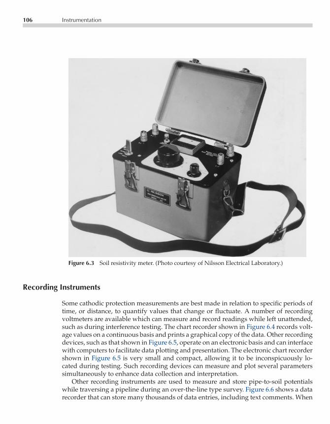
P1: FPVCE003-06 CE003-Peabody November 6, 2000 9:9 Char Count= 0
106 Instrumentation
Figure 6.3 Soil resistivity meter. (Photo courtesy of Nilsson Electrical Laboratory.)
Recording Instruments
Some cathodic protection measurements are best made in relation to specific periods oftime, or distance, to quantify values that change or fluctuate. A number of recordingvoltmeters are available which can measure and record readings while left unattended,such as during interference testing. The chart recorder shown in Figure 6.4 records volt-age values on a continuous basis and prints a graphical copy of the data. Other recordingdevices, such as that shown in Figure 6.5, operate on an electronic basis and can interfacewith computers to facilitate data plotting and presentation. The electronic chart recordershown in Figure 6.5 is very small and compact, allowing it to be inconspicuously lo-cated during testing. Such recording devices can measure and plot several parameterssimultaneously to enhance data collection and interpretation.
Other recording instruments are used to measure and store pipe-to-soil potentialswhile traversing a pipeline during an over-the-line type survey. Figure 6.6 shows a datarecorder that can store many thousands of data entries, including text comments. When

P1: FPVCE003-06 CE003-Peabody November 6, 2000 9:9 Char Count= 0
Equipment 107
Figure 6.4 Strip-chart recorder. (Photo courtesy of M. C. Miller Co.)
Figure 6.5 Electronic dual-channel recorder.(Photo courtesy of Corrpro Companies, Inc.)

P1: FPVCE003-06 CE003-Peabody November 6, 2000 9:9 Char Count= 0
108 Instrumentation
Figure 6.6 Electronic data recorder.(Photo courtesy of Corrpro Compa-nies, Inc.)
used with a distance measuring “chainer,” data can be gathered and plotted showingvoltage versus distance. Several of the accessories used in the over-the-line survey areillustrated in Section 2 of this chapter.
Wall Thickness and Pit Gages
While the corrosion engineer is primarily concerned with the elimination or reduction ofcorrosion, sometimes it is necessary to quantify the remaining wall thickness of a pipeline.

P1: FPVCE003-06 CE003-Peabody November 6, 2000 9:9 Char Count= 0
Equipment 109
Figure 6.7 Pipe pit gage. (Photo courtesy of KTA Tator and W. R. Thorpe Co.)
The traditional pit gage, as shown in Figure 6.7, is a very handy tool for the measurementof pit depth. These gages are small, reasonably accurate and can be carried easily in atoolbox or briefcase. Care must be taken to use them properly, and to understand theirlimitations.
For instance, on all but the largest diameter pipes, this instrument must be alignedlengthwise with a pipeline, and must rest on an even surface. On severely pitted orpartially coated structures, such a gage may offer only a rough estimation of pit depth,if it cannot be properly aligned. A more accurate pit gage is shown in Figure 6.8. It doesnot require such a large, flat surface for accurate positioning. However, it is more fragileas well as somewhat more expensive.
Another non-destructive device for gathering corrosion data is the ultrasonic wallthickness gage, such as shown in Figure 6.9. This device, and those similar to it, can ac-curately measure wall thickness using ultrasonic (sound) waves. They operate by com-puting the elapsed time between echoes produced when an ultrasonic pulse is passedthrough a material. By knowing the velocity of sound in that particular material, thethickness is calculated. Other more sophisticated versions offer features such as datastorage and data printing capabilities, and display-screens showing the actual wave-form and soundpath echo. These devices can detect and characterize flaws within thesteel plate itself, and some can measure wall thickness through various coatings. Allultrasonic measuring devices must be periodically calibrated and have certain impor-tant limitations to their use. Worn or improperly used transducers, for instance, can giveerroneous readings, sometimes twice or three times the actual value. Knowledge of thematerial being tested is also important, because the speed of sound varies from material tomaterial, and can be altered by temperature, heat treatment, and other material qualities.

P1: FPVCE003-06 CE003-Peabody November 6, 2000 9:9 Char Count= 0
110 Instrumentation
Figure 6.8 Dial type pit gage. (Photo courtesy of KTA Tatorand the L. S. Starrett Co.)
Current Interrupters
The ability to interrupt cathodic protection current is an important and frequently usedtechnique in cathodic protection testing. A variety of current interrupters are available,most of which offer the benefits of precision timing and the ability to synchronize multipleinterrupters. The device shown in Figure 6.10 relies on a quartz crystal for accuratetiming and can serve as a master unit to synchronize similar interrupters. Other devicesare manufactured with sophisticated timing clocks, which can be programmed to runpre-set timing cycles during the day (when surveys take place), and return to a closedcircuit at night (Figure 6.11). This feature saves time because the survey crew does notneed to return to the unit each morning for re-installation. It also minimizes structuredepolarization because of unnecessary off-cycling.
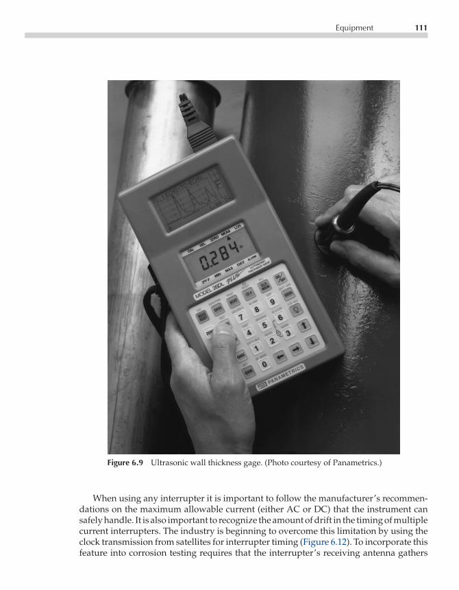
P1: FPVCE003-06 CE003-Peabody November 6, 2000 9:9 Char Count= 0
Equipment 111
Figure 6.9 Ultrasonic wall thickness gage. (Photo courtesy of Panametrics.)
When using any interrupter it is important to follow the manufacturer’s recommen-dations on the maximum allowable current (either AC or DC) that the instrument cansafely handle. It is also important to recognize the amount of drift in the timing of multiplecurrent interrupters. The industry is beginning to overcome this limitation by using theclock transmission from satellites for interrupter timing (Figure 6.12). To incorporate thisfeature into corrosion testing requires that the interrupter’s receiving antenna gathers

P1: FPVCE003-06 CE003-Peabody November 6, 2000 9:9 Char Count= 0
112 Instrumentation
Figure 6.10 Quartz crystal controlled current in-terrupter. (Photo courtesy of Nilsson ElectricalLaboratory Inc.)
frequent and accurate satellite communication data. If battery operated, these instru-ments will require monitoring to replace batteries regularly during extended surveys.
Pulse Generators and Analyzers
The pulse generator is gaining acceptance as an alternative to traditional current inter-ruption. The pulse generator is installed in the cathodic protection power supply andmomentarily interrupts the output in a precisely timed pattern. The interruptions are ex-tremely brief and occur in a repetitive cycle. Pulse generators can be installed in multiplerectifiers (or other CP power sources, including galvanic systems) and an “on/off” sur-vey conducted with a portable analyzer.

P1: FPVCE003-06 CE003-Peabody November 6, 2000 9:9 Char Count= 0
Equipment 113
Figure 6.11 Programmable current interrupter. (Photo courtesy ofM. C. Miller Co.)
Figure 6.12 Satellite controlled current interrup-ter. (Photo courtesy of Corrpro Companies, Inc.)

P1: FPVCE003-06 CE003-Peabody November 6, 2000 9:9 Char Count= 0
114 Instrumentation
The analyzer recognizes these multiple momentary current interruptions and, usingan algorithmic analysis, calculates the overall “off” potential of the protected structure.It is critical to ensure that all pulse generators are operating, and that they are each setto a timing cycle that exactly corresponds to the algorithm analyzer. These analyzersalso have a finite limit to the number of pulse generators that they can recognize, sothis must also be taken into consideration when surveying or interpreting survey data.When used correctly they offer the advantage of measuring “off” potentials at every testsite, without the installation of numerous specialized test stations. A disadvantage topermanent pulse generator installation is that the pulsing signal may be confusing tothe operators of neighboring utilities who happen to see this pattern during surveys oftheir own structures. To avoid this, permanently installed generators can each be set tosteady-state operation.
Pipe and Cable Locators
During the course of corrosion testing, it is sometimes necessary to determine the locationof buried items such as the pipeline being worked on, the location of foreign utilities,groundbed cables and other concealed metallic structures. The pipe and cable locatorcan be a great time-saver in such a case. Pipe and cable locators impress an electricalsignal onto the target line, and this permits a hand-held receiver to detect their location.Electrical contact with the metallic structure being located need not be made, althoughconductive locating is generally much more accurate than inductive. Figure 6.13 (a) and(b) show two commercially available instruments.
The type of signal that is transmitted to the pipe (or cable) can vary from manufac-turer to manufacturer, and can even be variable within a single locator. Alteration ofthe signal frequency allows the operator to select the most appropriate signal for theapplication. For example, poorly coated pipes, well coated pipes, shorted pipelines, andinsulated cables, might each be best located using different frequencies. It is imperativeto remember to set both the transmitter and the receiver to matching frequencies.
Other locator features can be useful in cathodic protection work. Some transmittershave a clamp accessory that can be clipped around a conductor to induce the signal,such as when tracing a live electrical cable. This technique saves time as well as enhancessafety. The clamp can be placed around an electrical conduit leading to a rectifier, forinstance, so that unlocking and opening the rectifier enclosure becomes unnecessary. Ofcourse, if the conduit contains multiple conductors, verification of a correct tracing maybe necessary.
Advances in locator technology have also enabled a variety of attributes to be incorpo-rated into pipe and cable locators. Depth measurement capability has greatly improvedand allows the operator to measure, with increasing confidence, the depth of the target.Other pipe locators have the ability to measure and trace the amount of signal current be-ing conducted by the pipeline or cable (Figure 6.14). These locators can trace the pipelineas well as improve the operator’s ability to analyze and evaluate the pipe’s current-carrying characteristics. Tools such as these are becoming accepted in locating electricalshorts to distribution networks. By tracing current flow and magnitude, unintended

P1: FPVCE003-06 CE003-Peabody November 6, 2000 9:9 Char Count= 0
Equipment 115
Figure 6.13(a) Pipe and cable locator. (Photo courtesy of Radiodetection.)
shorts can be rapidly found. Operator experience with pipe locators is valuable in utilityoperations in general, and particularly effective in cathodic protection administration.
Ammeter Clamps
The measurement of AC or DC current flowing through a pipeline or cable is obviouslya useful kind of measurement in cathodic protection work. However, shunts or “currentspans” may not exist at a location where a measurement is necessary. If the pipe orcable is made accessible, a portable non-contact ammeter clamp can measure the currentmagnitude and direction of flow. These devices rely on the relationship between current

P1: FPVCE003-06 CE003-Peabody November 6, 2000 9:9 Char Count= 0
116 Instrumentation
Figure 6.13(b) Pipe and cable locator. (Photo cour-tesy of Fisher.)
flow in a conductor and the electro-magnetic field that it generates. They use amplifyingcoils positioned around the pipe or cable such as shown in Figure 6.15. These clampsare quite specialized in that they must fit around the pipe being tested. They are alsoa tool for which there is no substitution in certain applications. They can be used ininterference testing, short locating, fault detection, and to identify bad insulating joints.The proper use of ammeter clamps requires careful attention to coil orientation, magneticinterference, nearby current flow, and polarity interpretation.
Insulator Checkers
Portable, battery-operated instruments that check the integrity of insulators find a veryvaluable place in cathodic protection and corrosion control.
Devices such as that shown in Figure 6.16 can not only identify shorted flanges,but when tested individually, can detect shorted bolt-sleeve-washer assemblies. Theycan also test other insulating assemblies, such as dielectric insulating unions. These

P1: FPVCE003-06 CE003-Peabody November 6, 2000 9:9 Char Count= 0
Equipment 117
Figure 6.14 Pipe and current tracing transmitter. (Photo courtesy of Radio-detection.)
instruments are affordable and can rapidly test critical insulating devices before they arebackfilled.
Test Rectifiers
Current requirement tests, groundbed testing and CP design work require portablepower supplies. A common automobile battery may suffice for some of these tests, butan adjustable power supply is more appropriate and more versatile (Figure 6.17). Mostrectifier manufacturers offer portable, adjustable power supplies that can be carried into

P1: FPVCE003-06 CE003-Peabody November 6, 2000 9:9 Char Count= 0
118 Instrumentation
Figure 6.15 Non-contact ammeter clamp. (Photo courtesy of William H. Swain Co.)
the field and used as convenient and temporary rectifiers. Optional features, such asbuilt-in current interrupters or unusual input/output options can be ordered with suchequipment.
Portable rectifiers, of course, require an AC power source. Low-current power sup-plies that are battery powered are also available. They are adjustable, and within thelimits of their battery source, are very useful in short-term tests, such as current require-ment testing, short-locating, and tests of steel casing-to-pipeline continuity. Figure 6.18shows one such compact power supply.
Holiday Detectors
Many corrosion engineers might never use a holiday detector because the pipelines theyprotect have been buried and, perhaps, well protected for many years. However, innew construction and during rehabilitation projects, these instruments are important tocorrosion control.
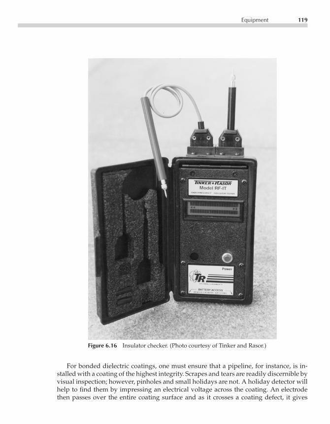
P1: FPVCE003-06 CE003-Peabody November 6, 2000 9:9 Char Count= 0
Equipment 119
Figure 6.16 Insulator checker. (Photo courtesy of Tinker and Rasor.)
For bonded dielectric coatings, one must ensure that a pipeline, for instance, is in-stalled with a coating of the highest integrity. Scrapes and tears are readily discernible byvisual inspection; however, pinholes and small holidays are not. A holiday detector willhelp to find them by impressing an electrical voltage across the coating. An electrodethen passes over the entire coating surface and as it crosses a coating defect, it gives

P1: FPVCE003-06 CE003-Peabody November 6, 2000 9:9 Char Count= 0
120 Instrumentation
Figure 6.17 Portable test rectifier. (Photo courtesy of Corrpro Companies, Inc.)
off an electrical discharge, or spark, which signals the operator that a holiday has beendetected. The operator can then mark the holiday for subsequent repair prior to companyacceptance. Holiday detectors must be selected for the thickness and type of coating be-ing tested. Excessive voltage can stress or damage thin coatings if the detector has beenset too high. Adherence to the manufacturer’s instructions is recommended, includingboth the manufacturer of the coating and the manufacturer of the holiday detector. NACEInternational also publishes a recommended practice (RP0274) for high voltage holidaydetection.
ACCESSORIES
Reference Electrodes and Coupons
Cathodic protection testing depends largely on the proper use and interpretation of pipe-to-electrolyte measurements. These determinations, in turn, rely on reference electrodes.

P1: FPVCE003-06 CE003-Peabody November 6, 2000 9:9 Char Count= 0
Accessories 121
Figure 6.18 Portable battery operated D.C. power supply. (Photo cour-tesy of Tinker and Rasor.)
Similarly, the use of buried test coupons is another tool in the evaluation of CP’s effec-tiveness.
The type of reference electrode the corrosion technician uses is dictated by theenvironment in which the electrode is used. Predominantly, copper-copper sulfate

P1: FPVCE003-06 CE003-Peabody November 6, 2000 9:9 Char Count= 0
122 Instrumentation
Figure 6.19 Portable copper-copper sulfate reference electrodes. (Photocourtesy of M. C. Miller Co.)
(CSE) electrodes are used, but other types are common and often necessary. Silver-silverchloride and zinc-zinc sulfate are also used in corrosion measurement applications, par-ticularly in high chloride environments such as seawater. All reference electrodes areavailable in transportable models as well as models manufactured for permanent burialor immersion.
Portable reference electrodes have a variety of configurations as seen in Figure 6.19.Note that some have a large sensing area for use where maximum soil contact is desirable.Other slim models can be used where only a narrow soil access is available, such as insmall test holes drilled through pavement. These can also be easily transported in a shirtpocket or briefcase.
The antimony electrode (Figure 6.20) is an accessory that can measure the pH (acidity)of soil or water. It does not measure a cathodic protection potential, but can help conductsoil evaluations, and is helpful during forensic work.
Reference cells are also used in permanent installations. These are buried or sub-merged adjacent to a structure with test leads routed to an accessible test station. Otherreference electrode configurations (Figure 6.21) incorporate a test coupon built into theelectrode assembly. These devices represent a discreet sample of the subject steel, usu-ally connected within the test station. The coupon simulates a bare portion of, or coatingholiday in, the steel. This device enables the corrosion engineer to determine the amountof protection being afforded the structure. The devices can also be disconnected (orinterrupted) from the CP system to evaluate the polarization level.
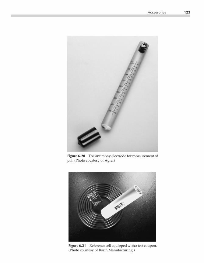
P1: FPVCE003-06 CE003-Peabody November 6, 2000 9:9 Char Count= 0
Accessories 123
Figure 6.20 The antimony electrode for measurement ofpH. (Photo courtesy of Agra.)
Figure 6.21 Reference cell equipped with a test coupon.(Photo courtesy of Borin Manufacturing.)

P1: FPVCE003-06 CE003-Peabody November 6, 2000 9:9 Char Count= 0
124 Instrumentation
When using test coupons, it is important to use an alloy identical to that of theprotected structure. Following coupon installation, it will take some time to stabilize thecoupon at a level representative of the true corrosion activity.
Reference electrodes should always be selected for compatibility with the environ-ment in which they will be used. Copper sulfate electrodes are easily contaminated bysaline or brackish environments that have high levels of ionic chlorides. If a portablereference electrode is suspected of contamination, it should be cleaned and re-filled withfresh solution. Reliance on a single electrode for field work is never advisable, for it pre-cludes both cell-to-cell comparison, and the redundancy of having a spare cell on hand.Reference electrodes require maintenance to ensure accuracy, and must be periodically“re-charged”. They should also be periodically checked against a standard to determineif further maintenance is required.
Reference electrodes also can be equipped with accessories to make them more ver-satile. Waterproof adapters can be fitted onto the cell, which attaches it to a long, well-insulated and waterproof wire and makes the electrode submersible. Electrode exten-sions can also be fabricated or purchased for over-the-line walking type surveys on land.
Meter Accessories
Meter manufacturers as well as corrosion specialty suppliers offer many accessories tobe used with corrosion test equipment. Wire reels, for instance, are indispensable formany test applications. They can be configured in many ways, dependent upon wiregage and length of cable. Figure 6.22 shows several of those available. The integrity ofthe insulation must be maintained for accuracy, as ‘skinned’ insulation can compromisemany measurements if the copper wire becomes shorted to other structures, or to earth.
Meter manufacturers also offer a variety of test leads, carrying cases, and complemen-tary accessories, such as temperature probes. These usually plug directly into the meterand will accommodate the variety of conditions encountered by a corrosion technician.Insulated leads and test clips are always recommended, especially if higher current orvoltage applications are encountered. Custom-made leads and connectors can also befabricated to suit a particular situation.
Portable shunts are available, some, such as in Figure 6.23, can plug directly into thevoltmeter and allow current measurement to be made at any cable connection point.As with any permanently installed shunt, portable shunts must be used with carefulobservation of rating and capacity.
Resistance Accessories
Several complementary accessories are available for use with a resistivity meter. Soilpins can be purchased, and should be selected for the degree of service to which theywill be subjected. A corrosion engineer with only an occasional need to measure soil re-sistivity might suffice with the use of large screwdrivers, or other improvised temporary

P1: FPVCE003-06 CE003-Peabody November 6, 2000 9:9 Char Count= 0
Accessories 125
Figure 6.22 Wire reels. (Photo courtesy of M. C. Miller Co.)
Figure 6.23 Portable shunt. (Photo courtesy of Agra.)

P1: FPVCE003-06 CE003-Peabody November 6, 2000 9:9 Char Count= 0
126 Instrumentation
Figure 6.24 Soil resistivity pins. (Photo courtesy of M. C. Miller Co.)
electrodes. Alternatively, a substantial amount of survey work, or work in highly com-pacted soil, might justify the purchase of more durable electrodes. Long stainless steelpins equipped with handles suitable for repeated hammering are available if needed(Figure 6.24).
If multiple soil-depth resistivity measurements are to be taken, a convenient selectorbox can be used. It enables the technician to install a long series of properly spacedpins into the ground, and then gather data for many soil depths without returning toreposition the pins. This is done by switching the selector box to connect the correct 4-pinarray to the resistance meter.
The soil box is a valuable accessory used in conjunction with a standard resistivity me-ter. Soil boxes are designed for connection to the potential and current terminals of thesemeters, usually with only a multiplication factor to remember (Figure 6.25). However,the soil box can permit the disadvantages of improper sample handling, compaction, andmoisture preservation. Nevertheless, the soil box offers substantial information aboutthe corrosivity of a particular soil, and can be valuable when combined with laboratorysoil work.
Close Interval Survey Accessories
A number of accessories have been developed to gather multiple pipe-to-soil potentialsin relation to distance. These include wire carrying and measuring backpacks, refer-ence electrode extensions, and numerous other devices to make the long pipeline survey

P1: FPVCE003-06 CE003-Peabody November 6, 2000 9:9 Char Count= 0
Accessories 127
Figure 6.25 Soil resistivity box. (Photo courtesy of M. C. Miller Co.)
accurate and efficient (Figure 6.26). Many of these systems are designed to work inconjunction with proprietary software and plotting programs. Close interval surveyequipment may also include related current interruption equipment that can be inte-grated into the survey to gather “on” and “off” data.
Figure 6.26 Close interval survey equipment. (Photo courtesy of Corrpro Compa-nies, Inc.)
P1: FPVCE003-06 CE003-Peabody November 6, 2000 9:9 Char Count= 0
128 Instrumentation
CARE AND MAINTENANCE
Correct handling and maintenance of corrosion test equipment used in the field will paydividends in ensuring the reliability of the instruments and the procurement of accuratetest data. The following suggestions are given as a guide.
Probably the greatest cause of damage to sensitive test equipment is inadequateprotection during transportation. When carrying equipment in cars or trucks, sensitiveinstrumentation should be protected from road shock and should be secured so thatthe various items of equipment will not slide about and knock against each other. Inaddition, electronic instrumentation should be protected from moisture and road dust.The corrosion engineer must also decide which instruments are needed on a routine basis,and which are better left in storage and carried into the field as necessary. Deployingevery imaginable instrument into the field may be impressive; however, it brings a greaterobligation to proper equipment care and maintenance.
Long-term reliability of corrosion test equipment also involves documentation andrecord keeping.
Meter serial numbers, warranties, instruction manuals, and purchase records shouldbe kept in an orderly fashion so that repair or replacement can be done as necessary withminimal interruption to productivity.
Calibration records should also be kept, particularly when survey work involves legalor regulatory issues. Oftentimes calibration must be traceable to the National Instituteof Standards and Technology (NIST3), and such documentation should be maintained.Evidence of traceability for a particular instrument is available from the instrumentmanufacturer, although certain limitations and fees are usually involved.
Portable instruments rely on batteries that are inexpensive and easily replaced, buteasily overlooked. The corrosion technician should carry spares for each type of batteryused. Consideration should be given to the use of rechargeable batteries for instrumentsusing larger, frequently drained batteries (Figure 6.27). Meters used infrequently shouldhave the batteries removed to prevent leakage and subsequent damage to the instrumentcomponents.
Copper sulfate reference electrodes should be kept clean and uncontaminated. Thecopper sulfate solution must be a saturated solution; that is, crystals are visible in the solu-tion at ambient temperature after sufficient time is allowed to reach solution equilibrium.The copper rod may be cleaned when it becomes encrusted or if it is suspected that thecopper sulfate solution is contaminated. The rod can be sanded with fine, nonmetallicsandpaper. The use of metal-containing sandpaper will embed foreign metallic particlesin the copper rod and can compromise accuracy. Disposal of used copper sulfate solutionis also now regulated in some areas because of its potential for environmental impact.Consult with local regulations before disposing copper sulfate solution.
Reference cells stored in or subject to freezing conditions can be filled with anti-freezesolution. These must be periodically refreshed, just as with ordinary electrodes. Electrodetips may occasionally require replacement, particularly if they are routinely used in closeinterval survey work.
3 National Institute of Standards and Technology, Gaithersburg, Maryland.

P1: FPVCE003-06 CE003-Peabody November 6, 2000 9:9 Char Count= 0
Care and Maintenance 129
Figure 6.27 Rechargeable battery. (Photo courtesy of Nilsson Electrical Laboratory.)
Always remember that test equipment should be handled and maintained in topworking condition. This is essential for optimum results when conducting field tests andsurveys. Even the most sophisticated instrumentation is of no value if used incorrectlyor improperly maintained.

P1: FPVCE003-07 CE003-Peabody November 2, 2000 17:49 Char Count= 0
Chapter7Ground Bed Design
Ronald L. Bianchetti and Steve McKim
This chapter will provide a guideline for design of anode ground beds and serveas a nucleus for the development of design procedures for the pipeline corrosionengineer.
LOCATING GROUND BED SITES
Previous chapters (3, 4 and 5) have provided basic considerations involved in decidingapproximately where cathodic protection (CP) current will be needed and how muchwill be required. Once these decisions have been made, specific installation sites forground beds may be selected and proper designs prepared.
In selecting ground bed sites, the most important consideration from a design stand-point is determination of effective soil resistivity. The discussion on measurement andanalysis of soil resistivity in Chapter 5 serves as a guide. Other considerations that mustbe taken into account when selecting a site include the following:
• Are other underground metallic structures within the area of influence surroundingthe ground bed? If so, they may pick up current from the ground bed and create astray current interference problem that will require corrective measures if the site isused. This is important when planning impressed current ground beds.
• Is the proposed site on or off the pipeline right-of-way? If off (as is apt to be the casewith impressed current ground beds), can right-of-way be procured? Check with thepipeline right-of-way department on this.
• If a rectifier-powered impressed current system is to be installed, is there a power linepresent? If not, is a power line extension from the nearest source practicable?
• Is the site reasonably accessible for construction and maintenance purposes?• Are there plans for building construction (new pipelines, highway development, or
other similar work) that will make the site untenable in the near future?
131

P1: FPVCE003-07 CE003-Peabody November 2, 2000 17:49 Char Count= 0
132 Ground Bed Design
In most cases, locations for galvanic anode installations are easier to select than thosefor impressed current ground beds because they usually can be placed within the pipelineright-of-way, are independent of power sources, and are relatively free of interferencewith foreign underground structures. Impressed current ground beds may be located atcertain sites by compromise rather than other sites with more favorable soil resistivity.
DESIGNING THE GROUND BED
Once ground bed locations have been selected for either impressed current or galvanicanode systems and the effective soil resistivities for design purposes have been deter-mined, the design process can proceed. Designs are reasonably simple when designcharts are available, and many companies utilize such charts. These charts are typicallybased on the type of anode and construction to be employed. Determining effective soilresistivity is prerequisite to all decisions before designing the system. Because of all ofthe variables involved, it should be recognized that the design calculations for completedground bed resistance may not be highly precise. The design engineer can consider thedesign successful if the final completed ground bed resistance is consistently within 10%of design calculations.
Impressed Current Ground Beds
Design charts for impressed current ground beds should be based on the types of an-ode construction adopted by the corrosion engineer for his pipeline system. Typicalconstruction sketches will be shown to illustrate principles involved, but others may beused if found more suitable for specific pipeline conditions.
Figure 7.1 illustrates one form of vertical anode installation. The figure includes theessential features only. The carbonaceous backfill surrounding the anode, when welltamped, serves two functions:
• Being of a very low resistivity, it has the effect of increasing the anode size withresulting reduction in resistance to earth, and
• Most of the current is transmitted to the backfill from the anode by direct contact sothat the greater part of material consumption should take place at the outer edges ofthe backfill column.
Since a positive potential (voltage) is impressed on the entire ground bed assembly,it is absolutely essential that all header cable insulation, anode pigtail wire insulation,the connection between anode and pigtail (a manufacturer’s function) and insulation ofconnections between pigtails and a header cable or cable runs to a test or junction becompletely intact and moistureproof. If this is not maintained, current will be dischargedthrough insulation imperfections, causing wires to corrode and sever in a relatively shortperiod of time, thus losing connections to all or part of the ground bed. Connectionsbetween header cable and anode pigtail must be of permanent low resistance. This may
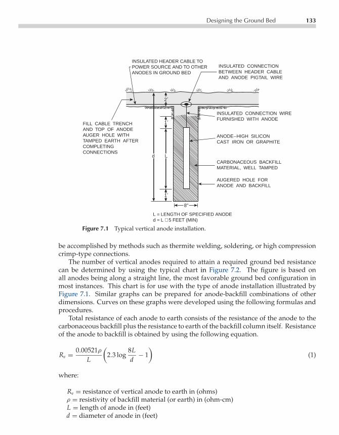
P1: FPVCE003-07 CE003-Peabody November 2, 2000 17:49 Char Count= 0
Designing the Ground Bed 133
INSULATED CONNECTIONBETWEEN HEADER CABLEAND ANODE PIGTAIL WIRE
INSULATED CONNECTION WIREFURNISHED WITH ANODE
ANODE_HIGH SILICONCAST IRON OR GRAPHITE
CARBONACEOUS BACKFILLMATERIAL, WELL TAMPED
AUGERED HOLE FORANODE AND BACKFILL
8"
1
2
d L
FILL CABLE TRENCHAND TOP OF ANODEAUGER HOLE WITHTAMPED EARTH AFTERCOMPLETINGCONNECTIONS
1
L = LENGTH OF SPECIFIED ANODEd = L + 5 FEET (MIN)
INSULATED HEADER CABLE TOPOWER SOURCE AND TO OTHERANODES IN GROUND BED
Figure 7.1 Typical vertical anode installation.
be accomplished by methods such as thermite welding, soldering, or high compressioncrimp-type connections.
The number of vertical anodes required to attain a required ground bed resistancecan be determined by using the typical chart in Figure 7.2. The figure is based onall anodes being along a straight line, the most favorable ground bed configuration inmost instances. This chart is for use with the type of anode installation illustrated byFigure 7.1. Similar graphs can be prepared for anode-backfill combinations of otherdimensions. Curves on these graphs were developed using the following formulas andprocedures.
Total resistance of each anode to earth consists of the resistance of the anode to thecarbonaceous backfill plus the resistance to earth of the backfill column itself. Resistanceof the anode to backfill is obtained by using the following equation.
Rv = 0.00521ρL
(2.3 log
8Ld− 1
)(1)
where:
Rv = resistance of vertical anode to earth in (ohms)ρ = resistivity of backfill material (or earth) in (ohm-cm)L = length of anode in (feet)d = diameter of anode in (feet)

P1: FPVCE003-07 CE003-Peabody November 2, 2000 17:49 Char Count= 0
134 Ground Bed Design
RE
SIS
TAN
CE
IN
OH
MS
IN
100
0 O
HM
-CM
SO
IL
10-FOOT ANODE SPACING15-FOOT SPACING20-FOOT SPACING25-FOOT SPACING
0 5 10 15 20 25 30
NUMBER OF ANODES
3.0
2.0
1.00.90.80.70.6
0.5
0.4
0.3
0.2
0.1
Figure 7.2 Typical vertical anode design chart.
Using a value of 50 ohm-cm for the resistivity of the carbonaceous backfill material,resistances are calculated for the backfill column and the anode (7 ft× 8 in and 5 ft× 2 inrespectively in this case). The difference between the two figures is the resistance fromthe anode to the outer edges of the backfill column. For the anode construction shownin Figure 7.1, this was calculated to be 0.106 ohm.
Resistance of several anodes in parallel can be calculated by the following equation:
Rv = 0.00521ρNL
(2.3 log
8Ld− 1+ 2L
S(2.3 log 0.656N )
)(2)
where:
Rv = resistance of vertical anode to earth in (ohms)ρ = resistivity of backfill material (or earth) in (ohm-cm)L = length of anode in (feet)d = diameter of anode in (feet)N = number of anodes in parallelS = anode spacing in (feet)
The dimensions of the backfill column (7 ft × 8 in in this case) are used in applying theformula. Curves for 10, 15, 20 and 25-ft anode spacing are included in the Figure 7.2. The

P1: FPVCE003-07 CE003-Peabody November 2, 2000 17:49 Char Count= 0
Designing the Ground Bed 135
curves do not include the anode internal resistance (anode to backfill). The resistancefor any number of anodes in parallel from the curves must be added to the internalresistance of one anode divided by the number of anodes in parallel. The effect of thisinternal resistance becomes less as the number of anodes is increased.
Curves of Figure 7.2 are for anodes in 1000-ohm-cm soil. The resistance for theselected number of anodes from the curves varies directly with the resistivity. For ex-ample, if a combination of anodes has a resistance of 0.40 ohm in 1000-ohm-cm soil(as indicated by the curves) but the soil resistivity for design purposes at the installa-tion site selected is 2400 ohm-cm, the ground bed resistance for the same number ofanodes is 0.40 × 2400/1000 = 0.96 ohms, plus the internal resistance. For a second ex-ample, assume the soil resistivity for design purposes was 750 ohm-cm, the resistanceof the same anode combination would be 0.40× 750/1000 = 0.30 ohm plus the internalresistance.
Extending this analysis, assume that a ground bed installation site has been se-lected where the effective soil resistivity for design purposes has been determined tobe 2800 ohm-cm. Assume that the nearest ground bed anode will be 300 ft from thepipeline and that No. 4 copper connecting cable will be used. Also assume that theground bed is to discharge 20 A at 24 V applied from a rectifier.
Before using the chart, the maximum permissible resistance of the anodes must bedetermined. This is necessary because, in addition to resistance to earth of the anodes,other considerations must be analyzed to determine the total circuit resistance. Theseinclude the following:
• Back voltage between ground bed and pipeline,• Resistance to earth of the pipeline at the ground bed location, and• Resistance of cable from the pipeline to power source and from the power source to
and along the anodes comprising the ground bed.
The back voltage is that which exists between the anodes and pipeline in oppositionto the applied voltage. For ground bed anodes with carbonaceous backfill, this willbe, usually, in the order of 2 V. Some areas of unusual soil composition may resultin higher back voltages but the 2-V figure is used commonly for design purposes un-less experience in a specific area dictates otherwise. In practice, the back voltage at aworking ground bed is determined by measuring the voltage between ground bed andpipeline (across the positive and negative rectifier terminals) immediately after switchingthe rectifier power OFF. The ground bed will always be positive to the pipeline. If theback voltage is 2 V, it means it will require 2 V of the rectifier source voltage to overcomethe back voltage before current can flow through the ground bed.
Resistance to earth of the pipeline depends on the quality of the pipeline coating.The better the coating, the higher the effective resistances at the ground bed location. Inthe example being used, if current requirement tests made at (or in the vicinity of) theselected ground bed location had indicated that 20 A of applied current would cause achange in pipeline voltage (1V) of −1.5 V to a remote copper sulfate electrode (CSE),the effective pipeline resistance would be 1.5/20 or 0.075 ohm.

P1: FPVCE003-07 CE003-Peabody November 2, 2000 17:49 Char Count= 0
136 Ground Bed Design
Cable resistance is the additive resistance of the cable from the pipeline via the powersource to the first anode of the ground bed (assuming that the line of ground bed anodesis perpendicular to the pipeline), plus effective resistance of the header cable along theline of anodes or individual anode cables. This effective header cable resistance is lessthan that of the full length of the ground bed because all current does not flow the fulllength of the ground bed but is diminished as each anode connected drains off its shareof current. Although subject to variations with differences in individual anode resistanceand possibly other factors, it is practical to use the resistance of one half of the groundbed header cable resistance as the effective header cable resistance. Table 7.1 includesdata on resistance of copper conductors in the sizes commonly used in pipeline corrosionengineering work.
With the above discussion in mind, the design of the vertical anode ground bed forthe example proposed can be estimated as follows:
• Maximum power source voltage will be 24 minus 2 V back voltage or 22 V.• For 20 A current output, circuit resistance can not exceed 1.10 ohm. This is determined
by using Ohm’s law (Voltage (V) divided by Current (I)=Resistance (R ), 22 V dividedby 20 A or 1.10 ohm.)
• Deductions from the circuit resistance must be made for the pipe-to-earth resistance(0.075 ohm in this example), and the resistance of the cable from the rectifier to thefirst anode. In this example use the resistance of 330 ft of No. 4 cable (300 ft distancegiven, plus 10% slack) that equals 0.082 ohms. The total resistance is determinedby adding the resistance to earth of the anodes plus the effective resistance of theground bed header cable, a variable, (0.075+ 0.082 = 0.157 ohms). These resistancesare deducted from the total circuit resistance allowance (1.10 ohm − 0.157 ohm =0.94 ohm).
• Make an assumption of the allowance to be made for the header cable resistance. Asa first try, assume that the anode resistance alone should be 0.90 ohm.
• Convert the 0.90-ohm anode resistance to a 1000 ohm-cm base to permit using thedesign chart. Because effective soil resistivity for design purposes for the example is2800 ohm-cm, the converted resistance is 0.90× (1000/2800) = 0.321 ohm.
• Using the chart of Figure 8.2, the indicated number of anodes at 20-ft spacing wouldbe at slightly over 11. For design purposes use 12 anodes. (The number of anodes atother spacing would be determined in similar fashion.)
• Header cable length for 12 anodes would be 11 spaces at 20 ft or 220 ft. Effectiveresistance would be approximately 110 ft of No. 4 cable or 0.0285 ohm. For designuse 0.029 ohm.
• Total anode plus header cable resistance for 12 anodes would then be ((0.308 ohm(from the chart)× (2800/1000))+ internal resistance (0.106/12 = .009)+ 0.029 = 0.90ohm which is within the desired value of 0.94 ohm.
• Following the same procedure for 11 anodes, total resistance would be approximately0.96 ohm, which is higher than the desired value, indicating that 12 anodes would bethe minimum number to be used at the 20-ft spacing.

P1: FPVCE003-07 CE003-Peabody November 2, 2000 17:49 Char Count= 0
Designing the Ground Bed 137
Table 7.1 Resistance of Copper Conductors
Resistance of Stranded CopperConductors in Ohms per FootTimes 10−3 at 25C1
General ConductorUse Size (Awg)
ImpressedCurrentGroundBeds
4/03/02/01/0
1246
0.05090.06420.08110.1020.1290.1620.2590.410
Galvanic AnodeInstallations
8
100.6541.04
PipelineTest Points
1214
1.652.62
InstrumentTest Leads
16182022
4.186.66
10.617.0
Correction Factors for OtherTemperature Follow:
MultiplyTemperature Resistance at
C = F 25C by:
−10 14 0.862−5 23 0.882
0 32 0.9015 41 0.921
10 50 0.94115 59 0.96120 68 0.98030 86 1.02035 95 1.04040 104 1.059
125C = 77F

P1: FPVCE003-07 CE003-Peabody November 2, 2000 17:49 Char Count= 0
138 Ground Bed Design
1 1
1
ANODE; HIGH SILICON CAST IRON OR GRAPHITE
ANODE CENTERED IN 1 × 1 CROSS SECTIONAL FILL OFTAMPED CARBONACEOUSBACKFILL
INSULATEDPIGTAIL WIREFURNISHED WITHANODE
INSULATED HEADER CABLETO POWER SOURCE ANDOTHER ANODES INGROUND BED
INSULATED CONNECTIONBETWEEN CABLE ANDANODE PIGTAIL WIRE TAMPED EARTH
FILL
2
2
L
L = LENGTH OF SPECIFIED ANODE
Figure 7.3 Typical horizontal anode installation.
Another important consideration in selecting the number of anodes is desired anodelife. This is discussed in detail in the Chapters 8 and 9 on ground bed materials. If theminimum number of anodes that will give a satisfactory low ground bed resistance willnot result in adequate life, the number of anodes would have to be increased accordingly.Although, as a general principle, vertical ground bed anodes are preferable to horizontalanodes, it may be necessary to use horizontal construction because of unfavorable soilconditions at depths reached by vertical anodes. A typical method of installing horizontalanodes is shown in Figure 7.3.
Figure 7.4 includes design charts that may be used for determining the resistance ofhorizontal anodes in parallel. These charts are based on the type of construction shownin Figure 7.3 with all anodes placed along a straight line.
The same general procedure is followed in determining the resistance from the anodeto the outer edges of the backfill as was used in Figure 7.2 except that the applicableformula (also derived from H. B. Dwight equations) is the following:
Rh = 0.00521ρL
(2.3 log
4L2 + 4LS2 + L21/2d S
+ SL− S
2 + L21/2L
− 1
)(3)
where
Rh = resistance of horizontal anode to earth in (ohms)ρ = resistivity of backfill material (or earth) in (ohm-cm)L = length of anode in (feet)d = diameter of anode in (feet)S = twice depth of anode in (feet)

P1: FPVCE003-07 CE003-Peabody November 2, 2000 17:49 Char Count= 0
Designing the Ground Bed 139
15-FOOT ANODE SPACING20-FOOT SPACING25-FOOT SPACING(CENTERLINE TO CENTERLINE)
0 5 10 15 20 25 30
NUMBER OF ANODES
3.0
2.0
1.00.90.80.70.60.5
0.4
0.3
0.2
0.1
RE
SIS
TAN
CE
IN
OH
MS
IN
100
0 O
HM
-CM
SO
IL
Figure 7.4 Typical horizontal anode bed design chart.
Using this procedure, the resistance in 1000 ohm-cm soil of one horizontal anode installedper Figure 7.3 is approximately 2.22 ohms (including 0.136 ohm internal resistance).No specific formula applicable to horizontal anodes in parallel is known. The curvesof Figure 7.4 were obtained by dividing the resistance of 1 anode (excluding internalresistance) by the number of anodes in parallel and applying paralleling factors obtainedfrom the curves of Figure 7.2. To the values obtained from the curves must be added anamount equal to the internal resistance of 1 anode divided by the number of anodes inparallel. To allow for the reduced distance between nearest portions of horizontal anodesat a given spacing compared to that for vertical anodes at the same spacing, parallelingfactors for 15 ft horizontal anode spacing were taken from the curve for 10 ft verticalanode spacing, and so forth. This is not at all rigorous but will serve as a reasonableguide.
As an example, the paralleling factor for 20 vertical anodes at 15-ft spacing (fromFigure 7.2) is 0.218 ohm. The resistance of one anode calculated from Eq 3 is 2.56 ohm.Paralleling factor = 0.218/(2.56/20) = 1.70. Using this factor for 20 horizontal anodesat 20 ft spacing, the parallel resistance would be 2.08 ohm (resistance of one horizontalanode excluding internal resistance) divided by 20 and multiplied by the factor.
(2.08/20)× 1.70 = 0.177 ohm (see Figure 7.4).
Another approach to horizontal ground bed construction involves the use of a con-tinuous strip of carbonaceous backfill with anodes located at intervals within the strip.Construction would be similar to that shown in Figure 7.3 except that the carbonaceous

P1: FPVCE003-07 CE003-Peabody November 2, 2000 17:49 Char Count= 0
140 Ground Bed Design
0 100 200 300 400 500 600
GROUND BED LENGTH IN FEET
2.0
1.00.9
0.8
0.7
0.6
0.5
0.4
0.3
0.2
0.1
RE
SIS
TAN
CE
IN
OH
MS
IN
100
0 O
HM
-CM
SO
IL
15-FOOT SPACING
Figure 7.5 Typical design for continuous horizontal anode.
backfill layer is continuous throughout the length of the ground bed. Figure 7.5 is adesign curve for determining the resistance of a continuous horizontal ground bed withanodes on 15-ft centers with the carbonaceous backfill strip starting 5 ft before the endof the first anode and ending 5 ft after the end of the last anode.
The curve in Figure 7.5 is based on the formula for a horizontal anode given earlierplus an allowance for longitudinal resistance of the carbonaceous backfill. This curveis based on carbonaceous backfill having 50-ohm-cm resistivity, a conservative valuebecause a good quality backfill, well tamped, should have less than this amount. Inusing this curve, as with the other design charts, effective soil resistivity must be knownwith reasonable accuracy.
Galvanic Anode Ground Beds
The design of galvanic anode ground beds involves procedures similar to those used forimpressed current ground beds. Design charts, however, differ somewhat with anode

P1: FPVCE003-07 CE003-Peabody November 2, 2000 17:49 Char Count= 0
Designing the Ground Bed 141
TO PIPELINE TO PIPELINE2
ANODE: ZINC OR MAGNESIUM
BACKFILLMIXTURE
AUGER HOLE
8"
6"
6"
BACKFILL,PACKAGED,SUPPLIEDWITH ANODE
17-POUND PACKAGEDMAGNESIUM OR ZINC ANODE
L
L = LENGTH OF SPECIFIED ANODE
Figure 7.6 Typical galvanic anode installation.
dimensions and backfill used with them. Galvanic anodes (see Chapter 9) use specialbackfill having resistivities in the order of 50 ohm-cm. Calculations for design charts inthis chapter, however, are based on a conservative figure of 300 ohm-cm. Using proce-dures described previously earlier in this chapter under Impressed Current Ground Beds,similar charts may be developed based on lower resistivity backfill mixtures. Figure 7.6illustrates two typical types of galvanic anode installation.
The following is a calculation procedure similar to those used for impressed currentanodes. The resistance to earth of a 17-lb packaged anode (at the left of Figure 7.6) isapproximately 7.17 ohms in 1000-ohm-cm soil. Resistance to earth of the longer anodes(at the right of the figure) will range from 3.48 ohms for a 1.4-in × 1.4-in cross sectionanode to 3.38 ohms for a 2-in × 2-in cross-section anode in 1000-ohm-cm soil. As statedabove, these figures are based on 300 ohm-cm chemical backfill resistivity. Comparablefigures using 50-ohm-cm backfill (which reduces the internal resistance between anodeand outer edge of backfill column) would be 6.36, 2.94 and 2.92 ohms respectively.
For vertical galvanic anodes in parallel, design curves are provided in Figure 7.7. Thecurves shown are for 17-lb magnesium anodes at 15-ft spacing and for 5-ft long zinc ormagnesium anodes at 15-ft spacing. Similar curves for other spacing may be calculatedby procedures described earlier.
Seventeen-pound anodes, being short, need not be installed horizontally except inspecific circumstances. Longer anodes may require horizontal installation at locationswhere soil conditions are not favorable for the more usual vertical configuration. Figure7.8 includes a design curve that may be used as a guide in determining the parallelresistance of 5-ft horizontal anodes centered in a 6-ft. length of 8-in × 8-in cross sectionclay-gypsum backfill in a 4-ft deep trench with 15-ft spacing, center to center, betweenanodes.

P1: FPVCE003-07 CE003-Peabody November 2, 2000 17:49 Char Count= 0
142 Ground Bed Design
APPROX. INTERNAL ANODE RESISTANCEIN 300 OHM-CM BACKFILL
17-LB MAG ANODE : 0.96 OHM5-FT LONG ANODE : 0.60 OHM
17-POUND PACKAGEDMAGNESIUM ANODES.15-FOOT SPACING.
5-FOOT LONG ZINC ORMAGNESIUM ANODES.15-FOOT SPACING.
0 5 10
NUMBER OF ANODES
15 20
0.2
0.3
0.4
0.50.60.70.80.91.0
2.0
3.0
4.0
5.06.07.0
0.1
RE
SIS
TAN
CE
IN
OH
MS
IN
100
0 O
HM
-CM
SO
IL
Figure 7.7 Typical design charts for vertical galvanic anodes.
0 5 10
NUMBER OF ANODES
15 20
0.2
0.3
0.4
0.50.60.70.80.91.0
2.0
3.0
0.1
RE
SIS
TAN
CE
IN
OH
MS
IN
100
0 O
HM
-CM
SO
IL
15-FOOT SPACING
Figure 7.8 Typical design chart for horizontal galvanic anodes.

P1: FPVCE003-07 CE003-Peabody November 2, 2000 17:49 Char Count= 0
Designing the Ground Bed 143
0 50 150100
GROUND BED LENGTH IN FEET
200 250 300
0.2
0.3
0.4
0.50.60.70.80.91.0
2.0
0.1
RE
SIS
TAN
CE
OF
BA
CK
FIL
L L
AYE
R I
N O
HM
S I
N 1
000
OH
M-C
M S
OIL
0.02
0.03
0.04
0.050.060.070.080.090.1
0.2
0.3
0.4
0.01
INT
ER
NA
L R
ES
ISTA
NC
E I
N O
HM
S
RESISTANCE TO EARTHOF BACKFILL LAYER
INTERNAL RESISTANCE
Figure 7.9 Typical design chart for horizontal continuous galvanicanode.
Typically little can be gained by installing individual galvanic anodes in a continuoushorizontal layer of backfill as described for impressed current ground bed installations.Longitudinal resistance of the higher resistivity backfill tends to prevent good currentdistribution along such a bed. If, however, continuous strip anodes are used (availablein both zinc and magnesium), this type of backfill construction becomes practical. Thedesign curve in Figure 7.9 may be used as a guide for continuous anode strips centeredin a continuous horizontal layer of clay-gypsum backfill, 8-in × 8-in cross section, in a4-ft deep trench.
As an example of galvanic anode ground bed design, assume a requirement involvingthe installation of vertical 2×2×60-in magnesium anodes (see Figure 7.6) in 800-ohm-cmsoil to furnish 0.5 A of protective current with the pipeline polarized to −1.0 V to CSE.Assume that anodes will be installed on 15-ft centers, that the nearest anode will be 20 ftfrom the pipeline, and that No. 8 copper wire will be used for the header cable. Assumethat effective resistance between pipeline and earth at the installation site is 0.4 ohm.
The driving voltage available to force current from the magnesium anodes throughthe circuit resistance will be the polarized open circuit potential of the magnesium usedless the polarized pipeline potential. Assume magnesium open circuit potential of stan-dard magnesium (Chapter 9) at −1.55 V to copper sulfate. The driving potential in thiscase, then, will be 1.55−1.00−0.10 (anode polarization) = 0.45 V. Maximum permissiblecurrent resistance to provide 0.5 A output will be 0.45 V/0.5 A = 0.90 ohm.

P1: FPVCE003-07 CE003-Peabody November 2, 2000 17:49 Char Count= 0
144 Ground Bed Design
From the 0.90 ohm circuit resistance, subtract the effective pipe-to-earth resistance(0.4 ohm in this case) and the resistance of No. 8 wire from pipe to first anode (0.02 ohmused in this case to allow for 35 ft which will permit slack and test point connections).The total circuit resistance is 0.90− (0.4+ 0.02) = 0.48 ohm for anode-to-earth resistanceplus effective header cable resistance. Using the design curve of (Figure 7.7), convert the0.48 ohm to a 1000 ohm-cm soil resistivity base.
0.48× (1000/800) = 0.60 ohm.
Using the curve for 60 in anodes at 15-ft spacing from Figure 7.7, seven anodes inparallel would be selected for the first attempt. Assuming 7 anodes, the resistance wouldbe 0.55 ohm (from the curve)×(800/1000) (to convert to the 800 ohm-cm soil resistivity atthe installation site)+ (0.60/7) (the internal anode resistance)+ 0.030 ohm (the resistanceof 45 ft of No. 8 wire, half the header cable length). This equals 0.556 ohm, which is toohigh. By increasing the number of anodes by trial and error, it is found that 9 anodes willbe the minimum number that will meet the requirements of the example. The resistance,by the above procedure, will be (0.45× (800/1000))+ (0.60/9)+0.039 = 0.466 ohm whichis within the 0.48 ohm requirement. The above calculations were made using the higherresistivity chemical backfill. Using the lower resistivity (50 ohm-cm) backfill, the internalanode resistance would be lower and the anode bed resistance lower.
A similar approach to that detailed above would be used for design problems inwhich other galvanic anode design charts included herein are employed to arrive at adesired value of anode bed resistance. The useful life to be expected must be consideredalso. See Chapter 9 for data on selection of galvanic anode materials, sizes, and lifecalculations.
DISTRIBUTED ANODE SYSTEMS
Distributed anodes, either impressed current or galvanic, should be considered when itis necessary to protect a limited area of pipeline. Typically, such systems are used onsections of bare pipeline or coated pipeline in congested areas where electrical shieldingprecludes effective protection with remote ground bed installations.
The principle of protection received from distributed anode or close anode systemsis that the length of pipeline protected by a single close anode depends on changingthe potential of the earth around the pipeline rather than changing the potential of thepipeline with respect to earth. The amount of earth potential change (and hence thelength of pipe that can be protected from a single anode) is a function of voltage impressedon the anode rather than the amount of current discharged by the anode.
Distributed Impressed Current Anodes
When designing distributed anode systems using an impressed current anode system,effective soil resistivity along the section of pipeline to be protected should be known.
P1: FPVCE003-07 CE003-Peabody November 2, 2000 17:49 Char Count= 0
Design and Installation of Deep Anode Cathodic Protection Systems 145
(See Chapter 5.) With this information, resistance of individual anodes can be calculatedusing procedures described earlier in this chapter. The voltage to be impressed is selectedand anode spacing is calculated using the following principles. Existing potentials toearth must be known along the section to be protected, so the earth potential changeneeded to attain a minimum potential of−0.85 V (pipe-to-close CSE) can be determinedat the midpoint between anodes. The parallel resistance of all anodes is calculated. Withallowances for header cable resistance and back voltage between pipeline and anodes,voltage and current requirements of the power source may be calculated.
It should be noted if relatively long distances are covered by distributed anodes fedfrom one power source, voltage attenuation resulting from potential drop in the headercable (current flowing through the cable resistance) will result in reduced voltage tothe more remote anodes than that impressed on those close to the power source. Thisshould be checked during the design phase. If the difference is significant, closer spacingbetween the more remote anodes may be required to attain the same level of protectionbetween anodes along the distributed anode system.
An important consideration in determining spacing between distributed anodes isthe additive effect of earth potential changes at midpoints between adjacent anodes. If,for example, the earth potential change at the midpoint between two anodes is 0.1 Vfrom one anode with design voltage impressed on it and is 0.1 V from the second anode,the total earth potential change will be 0.2 V at the midpoint. This should be consideredwhen planning spacing between anodes.
Distributed Galvanic Anodes
When protecting a section of line with distributed galvanic anodes by the earth potentialchange method, anodes must be close together. Wide spacing is not effective, contraryto what is true with impressed current anodes, because anode voltage is a function ofthe anode material (i.e. magnesium or zinc). Placing galvanic anodes at individual hotspots (using procedures described in Chapter 5) is a form of distributed anode systemused effectively on bare lines or pipelines that experience random leaks over time.
DESIGN AND INSTALLATION OF DEEP ANODE CATHODICPROTECTION SYSTEMS
Steve McKim
In the past quarter century, deep anode cathodic protection (CP) systems have becomean industry standard. While such installations can be very useful under most conditions,they are not applicable to all situations. This section discusses design considerationsthat may be used as a guide during planning and construction. Local restrictions mayinfluence installation of certain deep anode configurations, and communications withthe local authorities for further information is always advisable.

P1: FPVCE003-07 CE003-Peabody November 2, 2000 17:49 Char Count= 0
146 Ground Bed Design
DEFINITION
A deep anode system is an impressed current CP arrangement in which the anodes arelocated in wholly, or partially, electrically remote earth extending down vertically fromthe surface in a hole drilled for the purpose, or an existing hole. This achieves the sameresult obtained by locating anodes electrically remote laterally from the structure, andnear the surface as described earlier in this chapter.
USES AND BENEFITS
Deep anodes provide effective CP to facilities as diverse as underground pipelines,storage tanks, refineries, power plants, treatment plants, pile structures, and well casingsin areas where surface soil resistivities are either very high or, if reasonably low, areshallow and overlie high resistivity material. These conditions require large surfaceanodes too far from the structure to obtain reasonably low resistance electrically remotefrom the structure.
Deep earth formations must, however, have low enough resistivity to permit con-struction of a deep anode that radiates the volume of current at a reasonable necessaryimpressed voltage. In deep formations with low resistivity compared to surface soils,excellent current distribution along the structure is expected. Even where surface soilsare entirely satisfactory for surface anode design, deep anodes can be useful in congestedareas where surface anodes are difficult to locate so that they will be remote electricallyfrom foreign structures as well as from the structure being protected.
Because remote earth is obtained vertically, the deep anode can be placed within thestructure right-of-way, which is difficult with conventional surface-type remote anodes.As discussed earlier in this chapter, these remote earth properties provide optimum cur-rent distribution along the protected structure and minimize voltage gradient variation.These benefits allow installation of high output systems near foreign utilities and struc-tures with fewer negative side effects associated with surface anode systems, such asinterference with foreign structures, hydrogen embrittlement of susceptible steels, andcathodic coating degradation.
Installing systems at greater intervals reduces the overall cost of CP. The compactinstallation means less foreign utility damage during installation and less chance of sub-sequent system damage from other construction activities. Fewer systems mean fewerlocations to coordinate rectifier power and negotiate easement rights, fewer rectifiers tomaintain and less interference to investigate, correct, and monitor.
Installing multiple anodes in one carbon column achieves maximum anode currentdischarge balance. The high level of carbon compaction in deep anodes provides maxi-mum electronic current discharge, thereby increasing anode life. The high probability forground water provides the lowest possible circuit resistance. Properly installed ventingsystems minimize the risk of gas blockage and allow for anode irrigation with potable

P1: FPVCE003-07 CE003-Peabody November 2, 2000 17:49 Char Count= 0
Design Considerations 147
water. Inherently low circuit resistance of these anode systems minimizes the costs ofAC power consumption. Note that many of the benefits of deep anodes are reducedsubstantially if the designer attempts to install too few systems at too great intervals. Inareas with foreign underground structures, the maximum recommended current outputis 30 A.
DESIGN CONSIDERATIONS
Figure 7.10, represents a typical deep anode installation.Standard features include nonmetallic vent pipe, active column consisting of multiple
anodes placed between 5 and 20 ft apart and backfilled with coke breeze (carbon), andan inactive column consisting of nonconductive backfill and sanitary well seal.
Other early deep anode configurations proved successful, although their use hasdiminished in recent years. These configurations included carbon steel pipe or heavysteel rails in place of fabricated anodes. Another less common deep anode configurationutilizes multiple anodes attached to a single header cable instead of individual cablesfrom each anode. Looping the anode header cable back to the rectifier from each endwill increase design reliability.
2” min. annularcement well sealaround vent pipe
100’min.
ToRectifier or
J-box
2” min. sch. 40PVC vent pipe with
perforations inanode interval
Entire 10” wellbore cementedthrough surface
formations
2’ min. orabove
flood plane
10”
Coke breeze anodebackfill (fluid or
granular)
Impressed currentanode (numberand size varies)
Figure 7.10 Typical deep anode ground bed in normal soil strata.
P1: FPVCE003-07 CE003-Peabody November 2, 2000 17:49 Char Count= 0
148 Ground Bed Design
Soil Resistivity
Resistivity of deep formations may be determined by several techniques. Informationgained from existing nearby deep anodes is most valuable. Histories of current outputreadings from individual anodes can indicate relative resistivity of downhole formations.Histories of rectifier outputs can indicate total anode bed resistance values. Existing soillogs may be available from nearby water wells or monitoring wells. This informationcan provide clues to the relative resistivity of downhole formations.
The four-pin method of measuring soil resistivity may be used in some instances.Techniques described in Chapter 5 are applicable. After determining surface soil re-sistivities in the usual manner, deep formation resistivities may be measured with,first, pin spacing of 50 ft and then with spacing increased progressively by 50-ft in-crements until it is felt that the location has been explored satisfactorily. Relatively thinstrata of either high or low resistivity may be missed, but average conditions will bedetermined. Measurements may be made to depths of several hundred feet but resis-tance values obtained will be so low that the DC method will have to be used in mostcases. The measured change in voltage between potential pins will be small, requir-ing high impedance electronic circuitry. Data analysis can be achieved as outlined inChapter 5.
Obviously, when using the four-pin test to measure at greater depths, the soil pinswill be spread over a wide area (1500 ft, for example, from first to last pin for a readingto a depth of 500 ft). This requires a large clear area. For accurate results, the pins mustremain clear of all underground structures (pipelines, cables, pole line grounds, etc.)that could pick up or discharge a portion of the test current and upset the geometry ofthe test. Due to the free space requirements, four-pin measurements to sufficient depthare usually impractical in urban areas.
If existing wells can be found in the area being investigated and if the length ofcasing and/or tubing is known, resistance of such structures may be measured to remoteearth. From this, the effective soil resistivity may be estimated to a depth equal to thelength of casing and/or tubing. This is done by application of the Dwight formula fora single vertical anode and solving for soil resistivity. Other methods of measuringdeep soil resistivity, such as electromagnetic conductivity, are cited by Morgan in CP,second edition, NACE, 1993. Opportunities for application of these methods may beinfrequent.
Probably the most effective method of proving a location is to drill a small pilot hole toa depth of the proposed deep well. If natural water is not encountered, the hole must befilled with potable water to measure the downhole resistance. A single anode is lowereddown the hole with a long attached wire connected to the structure in series with a battery(or other DC power source) and an ammeter (shunt). By measuring the current output ofpower source voltage at intervals as the test anode is lowered, a profile of current outputwith depth can be developed. This profile will reveal the best permanent anode locationsopposite the more highly conductive earth layers, as indicated by the highest currentoutputs from the test anode. If the pilot hole proves satisfactory, it may be drilled out

P1: FPVCE003-07 CE003-Peabody November 2, 2000 17:49 Char Count= 0
Vent Pipes 149
to full size for a permanent deep anode installation. Applying test anode resistance anddimensions to the Dwight formula at favorable anode locations may determine effectivesoil resistivity. Averaging the values obtained through that part of the hole where anodescould be installed would give a figure that may be used for designing the permanentinstallation.
Upon developing a figure for effective soil resistivity, the resistance for a permanentsystem may be based on the resistance of a single vertical anode, using the Dwightformula. As a last resort in areas of varying soil resistivities, it may be advantageousto install the deep anode before sizing the rectifier. This will allow actual resistancemeasurement and accurate rectifier ratings.
Well Dimensions
Common deep anode depths range from 50 ft to 500 ft. Prominant geologic formationsnear the proposed location may control final depth. Deeper installations may providemore remote earth and allow larger coverage, they also allow for more anodes, which willincrease system life. Local regulatory authorities may constrain the design philosophy,so early contact is recommended.
Most anodes have a nominal diameter of 10 in, which is achieved with a standard9 7
8 in rotary drill bit. This diameter provides the most cost-effective combination ofsystem life, installation cost, and operation expense. Other common drill bit diametersused for deep anodes are 6 in, 7 7
8 in, 8 34 in, 10 5
8 in and 12 14 in. Smaller diameters reduce
initial installation cost; however, they also shorten system life by reducing the bulkmass of carbon available for consumption. Smaller diameters also raise overall circuitresistance, which increases rectifier power consumption costs. Larger diameter wellsreverse these effects, but cost of construction increases exponentially. Diameters largerthan 9 7
8 in become quite costly in hard formations. Applications of Dwight equationsindicate a more efficient reduction in anode resistance by increasing the length of activeanode column rather than by increasing the diameter of active column.
VENT PIPES
All deep anode installations should include a method of venting produced gases tothe atmosphere. Lack of ventilation can lead to gas blockage of anodes and eventualsystem failure. Ventilation is normally accomplished by installing nonmetallic pipe with adiameter between 1 in and 2 in. The vent pipe is perforated throughout the active columnand solid through the inactive column. Standard perforations range from 0.006 in wideslots to 1
4 in diameter holes and are commonly placed every 6 in of pipe length. Toprevent plugging with inactive column backfill, perforations should end even with topanode.
P1: FPVCE003-07 CE003-Peabody November 2, 2000 17:49 Char Count= 0
150 Ground Bed Design
Schedule 40 PVC is the most common material used for vent pipe. Schedule 80 is onlyrequired when head pressure from deep cement well seals could cause pipe collapse.Upper end of vent pipe should be terminated so produced gases are allowed to dissipatenaturally to the atmosphere. Termination should be above any flood plain elevation.Vent pipe installation should be designed to allow for eventual well destruction. De-struction procedure could be regulated by local regulatory authorities and may includefilling vent pipe with nonporous materials.
Anode Suspension Systems
The standard method of installation is to lower each anode by its attached wire, suspendit at the desired depth, and tie it off at the surface. This technique allows adjustment ofanode position to low resistance soil formations and also provides a ready method totest for proper carbon backfill settlement by pulling on suspended anode wires.
Some installations have separate suspension systems to hold anodes and eliminatestress on the attached wires using ropes, steel pipe, or the vent pipe. Anode suspensionsystems are usually not required when following proper loading procedures. Use of1 1
2 -in diameter steel pipe is the most common suspension system. However, it requiresdielectric unions between anodes to allow resistance logging during backfill. Anotherdisadvantage of using a metallic support material is its eventual corrosion due to contactwith the anode circuit. This may complicate eventual well destruction.
Use of PVC vent pipe for suspension eliminates need for dielectric unions but isextremely dangerous during installation. PVC vent pipe suspension is not recommendedbecause of the dangers associated with vent pipe joint separation during loading. Sepa-ration will lead to downhole free-fall of anodes, which could result in injury to theinstallation crew.
Anode Centering Devices
Anode centralizers may be installed to ensure that carbon backfill surrounds each anode.Centralizers should be designed to prevent damage to anode wires during installationand allow anode movement in the well without snagging on downhole formations orother anode assemblies.
Carbon Backfill
High quality calcined petroleum coke is recommended for all deep anode installations.Granular carbon sinks readily in fresh water and is normally poured directly from thebag into the well. Fluid coke is comprised of fine carbon particles that compact tightlyaround anodes. Because of small particle size, fluid coke should be pumped from the

P1: FPVCE003-07 CE003-Peabody November 2, 2000 17:49 Char Count= 0
Vent Pipes 151
Water bearingformations with“questionable”water quality
Contaminatedsurface water canenter through vent
pipe opening
PVC vent pipe withperforations inanode interval
Permeable cokebreeze anode
backfill (fluid orgranular)
Water bearingformation withpotable water
quality
Imperviousaquitards such as
clay orconsolidated rock
Permeable backfill(gravel or sand), orinadequate cement
surface seal
Potential crosscontamination of
aquifers
Figure 7.11 Typical deep anode ground bed without surface seal.
bottom up using a pipe installed for this purpose. Fluid coke should normally be allowedto settle overnight and sounded prior to installation of inactive column.
Inactive Column and Well Seals
To eliminate anode current leakage up the inactive column, the upper section of deep an-odes should be backfilled with nonconductive materials. Materials include PVC casing,sand, gravel, and cement. Sand bridges easily during installation and is not recom-mended. Depth of inactive column will depend on current distribution requirements.Pea gravel backfill above the active column will increase the probability for ground waterrecharge. However, long columns of porous backfill can lead to commingling of aquiferswith differing water qualities.
All deep anodes should include a nonporous sanitary well seal in upper section ofinactive column. Depth of seal should be 50 ft minimum and could be in excess of 100 ft.Seal materials include cement, concrete, and specially formulated bentonite. Depth maybe dictated by local regulatory agency.
Conductor casings may be required to prevent caving of surface formations duringinstallation. Steel casing should be removed from inactive column within 50 ft of activecolumn. PVC casings can be left in inactive column, but should be cemented into placeto provide sanitary well seal. Top of casings must be sealed to prevent surface runoff thatcould lead to contamination of downhole aquifers. Size well diameter to provide 2-inminimum annular space around outside diameter of casing for proper seal placement.

P1: FPVCE003-07 CE003-Peabody November 2, 2000 17:49 Char Count= 0
152 Ground Bed Design
2” min. annularcement well sealaround casing
100’min.
ToRectifier or
J-box
2” min. sch. 40PVC vent pipe with
perforations inanode interval
10” PVC casingcemented through
potentialcontamination
2’ min. orabove
flood plane
10”
Coke breeze anodebackfill (fluid or
granular)
Impressed currentanode (numberand size varies)
Figure 7.12 Typical deep anode ground bed in contaminated soil strata.
In potentially contaminated formations, surface casing should be cemented into placebefore drilling active column. This should eliminate cross contamination during instal-lation and operation of anode system.
INSTALLATION CONSIDERATIONS
Deep anodes are normally drilled with truck-mounted rotary drilling equipment. Typicalequipment circulates water-based drilling mud to maintain well integrity and removedownhole cuttings. Compressed air circulation systems may be advantageous in lim-ited situations where downhole formations allow their use. Installation procedures arecritical, so use only fully qualified drillers.
Loading Procedures
As previously mentioned, deep anodes are ordinarily drilled with direct mud rotaryequipment. After reaching desired depth, downhole mud slurry must be thinned tonearly the viscosity of fresh water to allow proper carbon settlement around anodes.Thinning is performed by pumping potable water from the bottom up through mudcirculation system until it returns to surface in well bore. Accurate well thinning iscritical to system installation.

P1: FPVCE003-07 CE003-Peabody November 2, 2000 17:49 Char Count= 0
Installation Considerations 153
Drillers familiar with proper thinning procedures are essential. Higher downholefluid viscosities provide more resistance to caving of formations, but slow carbon settle-ment. Lower viscosities speed carbon settlement, but can lead to caving of downholeformations. Caving formations can bridge in well bore or settle around anodes. Theseconditions prevent carbon settlement around anodes, which will significantly decreasesystem performance and life.
After thinning, drill pipe is removed from well to allow system loading. Vent pipe isusually lowered first and tied into position. Anodes are lowered by their attached wireto the desired elevation and tied off at the surface. After anodes are placed at desiredelevations, carbon backfill is poured or pumped downhole. Anode resistance loggingbefore, during, and after carbon backfill provides proof of proper carbon settlement.Settlement of top-loaded granular carbons normally occurs within 1 hr. Settlement ofpumped fluid carbons normally takes 6 to 12 hr. Total settlement should occur beforebackfill of inactive column.
Site Layout
Deep anode installation equipment usually includes portable rotary drill rig, mud circu-lation system, water truck, drill mud and cuttings containment system, material trailer,and support equipment.
Drill rig masts are normally between 20 ft and 40 ft high. Safe and legal clearancefrom overhead power lines and other obstructions is mandatory.
Mud circulation pit
Mud filled well bore
Power system
Mud circulation system
Draw worksRig mast
Drill pipe and bit
Rotary table
Mud pit throat
Figure 7.13 Typical portable rotary mud drill rig.
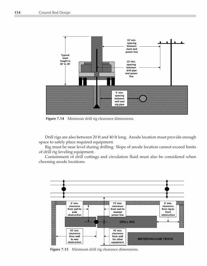
P1: FPVCE003-07 CE003-Peabody November 2, 2000 17:49 Char Count= 0
154 Ground Bed Design
10’ min.spacingbetweenmast and
power lineTypicalmast
height is30’ to 45’
5’ min.spacingbetweenwell andu/g pipe
13’ min.spacingbetweendrill pipe
and power line
Figure 7.14 Minimum drill rig clearance dimensions.
Drill rigs are also between 20 ft and 40 ft long. Anode location must provide enoughspace to safely place required equipment.
Rig must be near level during drilling. Slope of anode location cannot exceed limitsof drill rig leveling equipment.
Containment of drill cuttings and circulation fluid must also be considered whenchoosing anode locations.
Figure 7.15 Minimum drill rig clearance dimensions.

P1: FPVCE003-07 CE003-Peabody November 2, 2000 17:49 Char Count= 0
References 155
Woodblocks
under mudpit to level
fluid
Maximumwidthwiseslope is 1’
rise in8’ run
Maximumlengthwiseslope is 1’
rise in10’ run
levelling
jack,typical of 3
Figure 7.16 Maximum drill rig site slope dimensions.
REFERENCES
Derived from equations in “Calculation of Resistance to Ground”, by H.B. Dwight. ElectricalEngineering, p. 1319 (1936) December.Derived from equations in the book by Erling D. Sunde. “Earth Conduction Effects in TransmissionSystems.” D. Van Nostrand Co., Inc. (1949).

P1: FPVCE003-08 CE003-Peabody November 6, 2000 9:34 Char Count= 0
Chapter8Impressed CurrentCathodic Protection
Ronald L. Bianchetti
Rectifiers are used more than any other source of impressed current power. Areas dis-cussed include rectifier types, rectifier selection, specification requirements, and typicalinstallation details. Various types of impressed current anodes and components thatmake up an impressed current system are also presented.
RECTIFIER TYPES
Cathodic protection (CP) rectifiers have the following major components. These typ-ically include a transformer to step down AC line voltage to low voltage AC on thesecondary with a tap arrangement to permit selecting a range of voltage, a rectifyingelement (usually full wave silicon diodes for rectification), and a housing for outdoormounting. These components are supplemented by an AC circuit breaker and DC outputmeters. Both single-phase and three-phase units are in common use. Figure 8.1, illustratesdiagrammatically single-phase and three-phase units of the full-wave bridge-connectedtype.
Where electrical storm activity is prevalent, it is advisable to provide protectionagainst lightning damage.
• Lightning surges may occur from the electric distribution line (the more probable)and/or
• Surges coming from the pipeline (both from lightning and AC ground fault)
157

P1: FPVCE003-08 CE003-Peabody November 6, 2000 9:34 Char Count= 0
158 Impressed Current Cathodic Protection
GROUNDCONNECTIONFOR RECTIFIERCABINET
TO GROUNDBED
TO GROUND BED
TO PIPELINETO PIPELINE
AA
VV
(−) (+) (−) (+)
+
−
AC3 PHASESUPPLY
AC1 PHASESUPPLY
STEP-DOWN TRANSFORMERS WITH VOLTAGE ADJUSTINGTAPS ON SECONDARYWINDINGS
BRIDGE-CONNECTEDRECTIFIER STACKS.
GROUNDED SHIELDBETWEENPRIMARY ANDSECONDARYWINDINGS
ARROW HEADINDICATESDIRECTION OFCURRENT FLOWTHRU ELEMENT+
−
SHUNT
3-PHASE UNIT
1-PHASE UNIT
Figure 8.1 Rectifier schematic diagrams.
Specifying rectifiers having transformers with an electrical shield between primary andsecondary transformer windings may provide some protection from lightning surges.Such a shield (shown in the figure), when grounded properly, intercepts the high voltagepeak surge of a lightning pulse and carries it to ground. Otherwise, it can break downa rectifying element and may burn out the element. Low voltage lightning arrestorscan also be placed across rectifier terminals and may provide protection from lightningsurges from the pipeline. Neither type of protection, however, is effective against a directstrike to the rectifier itself.
Rectifier manufacturers produce units for CP applications with a wide range of out-puts. Data are available in the supply catalogs of CP equipment. Three general housingtypes are available. Ventilated housings that provide for convection air cooling are usedfor most pipeline applications. Where highly corrosive atmospheres exist (marine orindustrial, for example), the equipment may be oil-immersed in a tank-type housing.For locations subject to hazards and explosives an explosion proof housing is availablefor oil-immersed units. Figure 8.2 illustrates the appearance of typical air-cooled andoil-immersed units.

P1: FPVCE003-08 CE003-Peabody November 6, 2000 9:34 Char Count= 0
Rectifier Types 159
Figure 8.2 Typical rectifiers: (left) air cooled unit; (right) oil immersed unit. (Courtesy of UniversalRectifier, Inc.)
Rectifying elements typically used in units today are silicon diodes. A silicon diodehas high resistance to current flow in one direction and low resistance in the other. Thischaracteristic makes rectification possible. The diagrams of Figure 8.1 show that for agiven direction of current flow in the transformer secondary winding, the current canflow on only one route through the rectifying element (in the direction of the arrowheads). This flow is out the positive terminal to the ground bed and back from thepipeline connection to the negative terminal. When the direction of current flow in thetransformer secondary reverses (this occurs 120 times at normal 60-cycle AC powerfrequency), the current will take a different route through the rectifying element but willstill flow out at the positive terminal and back at the negative terminal. The result isdirect current (DC).
A rectifying diode is rated by the manufacturer for specific maximum current flow ata given ambient temperature and for maximum inverse voltage (the voltage impressedacross the element in the high resistance direction). Diodes are assembled into stacksor assemblies with series-parallel combinations to attain the over-all DC voltage andcurrent rating needed for the rectifier produced. In older rectifiers, the rectifying elementswere selenium stacks or discs, but modern rectifiers use mainly diodes as rectifying ele-ments. Rectifying elements have been continuously improved over the years in operatingcharacteristics and efficiency. The rectifier user is advised to review developments in thisfield and replace older rectifying elements with improved stacks when justified by theimproved characteristics and efficiency of newer ones.
Cathodic protection rectifiers may be equipped with filters in the DC output whichsmooth out the ripple in the rectified DC and permit higher over-all efficiency. Thesefilters are practical where savings in power cost justify the additional investment.

P1: FPVCE003-08 CE003-Peabody November 6, 2000 9:34 Char Count= 0
160 Impressed Current Cathodic Protection
Under certain circumstances, “constant potential” rectifiers are useful on pipelinesystems. Such rectifiers are designed to maintain a constant protective potential on thepipeline at the rectifier location, which changes to match pipeline current requirements.Applications include areas subject to stray current from transit systems or in miningoperations where potential variations are not beyond the corrective capacity of this typeof unit. Use with ground beds subject to wide seasonal variations in resistance (wet todry) is also included.
Constant potential rectifiers (see Figure 8.3) differ from more conventional rectifiers(which require manual adjustment of transformer taps to change output) in that a sensingcircuit that maintains continual checks on the pipe-to-soil potential changes the outputcurrent automatically. Typically, this can be accomplished by burying a permanent ref-erence electrode at the point where constant pipe-to-soil potential is to be maintained.
Once the rectifier is adjusted for the desired pipe-to-soil potential, any increase inabsolute value of this potential serves (through the electronic controller) to increase thereactor reactance. This cuts the output current back until a balance at the preset potentialis regained. Likewise, any decrease in absolute value of this potential between pipelineand reference electrode will cause the rectifier output current to increase automaticallyuntil balance is regained.
SELECTION OF RECTIFIER SIZE
Rectifier size (output rating) will depend primarily on the current requirement at theinstallation site and the output voltage required to force the current through the pipelineto ground bed circuit resistance. Current requirement tests, or other design procedures,determine the amperage. Circuit resistance is determined by the ground bed design asdiscussed in Chapter 7.
The output voltage rating should be sized 15 to 25% over the design-calculated valueto allow for any change in ground bed resistance. This permits maintaining full ratedoutput when ground bed resistance goes up as the anodes deteriorate with age. Finaloutput ratings for current and voltage can then be coordinated with standard outputratings defined on the rectifier name plate or manufacturer’s catalogue data.
Initial rectifier current ratings can give some understanding of future system require-ments as outlined in the following examples. For example, the current needed to protecta section of bare line is not likely to increase with time, the rectifier may be sized tomeet the existing design current requirements. On the other hand, a newly laid well-coated pipeline may initially require only a small amount of current, but as the coatingstabilizes with time (or deteriorates from soil stress, temperature effect, etc), it may re-quire several times the initial current. In these cases, it is practical to install rectifiers hav-ing maximum current capacity several times greater than the initial requirement. Coatedlines that have been in the ground for a long enough time to become well stabilized donot tend to require as much reserve capacity. No firm rules can be established, however,

P1: FPVCE003-08 CE003-Peabody November 6, 2000 9:34 Char Count= 0
Selection of Rectifier Size 161
AC SUPPLY
CIRCUIT BREAKER
TRANSFORMER
SATURABLECOREREACTOR(SCR)
ELECTRONICCONTROLLER
SHUNT
RECTIFIER STACKTO GROUND BED
REFERENCE ELECTRODEPIPE
−
+
A
V
Figure 8.3 Typical constant potential rectifier diagram.
because variables such as length of pipe section protected, coating used, changes in soilconditions, probable temperature effects, and other conditions will apply in each case.Experience with conditions on the pipeline corrosion engineer’s own system will helpto make proper current rating determination.
When time permits, some pipeline corrosion engineers design and install impressedcurrent ground beds before deciding on the rectifier rating. Following this procedure, itis possible to measure the installed circuit resistance and make new current requirementtests using the completed ground bed. Rectifier voltage and current ratings may beselected with full assurance that the installation will work as planned. Although results

P1: FPVCE003-08 CE003-Peabody November 6, 2000 9:34 Char Count= 0
162 Impressed Current Cathodic Protection
are positive, this procedure does require more time and involves additional expense forrepeat visits by the construction crews to make rectifier installations. However, whenground bed designs can be prepared with reasonable accuracy, this procedure is notnecessary.
In determining power costs, the corrosion engineer should recognize that the smallerrectifiers along the pipeline (well coated pipelines particularly) may draw so little powerthat the costs do not exceed the power company’s minimum billing (where applicable).In such instances, relative efficiency of the rectifier may have little bearing on economicchoice.
Although rectifiers operating on three-phase power are more efficient than single-phase units, three-phase power may be available at relatively few locations along apipeline. Where it is available, the choice between single-phase and three-phase unitsshould be based on a relative cost study. Results of this study can be expected to favorthree-phase units for large installations.
The use of filters for improvement in efficiency should be considered only when theywill reduce the net annual cost of the complete installation. The savings will be a resultof a reduction in power cost. Applicable power rates must be determined when makingcost comparisons. Rectifier manufacturers who furnish filters for their equipment shouldprovide data on efficiency improvement.
RECTIFIER SPECIFICATIONS
After deciding on the size and type of rectifier to be used, ordering specifications mustinclude at least the following information in order to ensure obtaining the correct unitwhen purchasing from the standard lines of rectifier manufacturers.
1. AC input: Voltage, single or three phase and frequency. For example: 120/240 V,single phase, 60 cycles. (The expression 120/240 means that the unit may be fieldconnected for operation on either 120 or 240 V AC).
2. Maximum DC output in amperes and volts.3. Air-cooled, oil-immersed, or oil-immersed and explosion-proof.4. Pole mounting, wall mounting, or floor (pad) mounting.5. Silicon type rectifying element and either full wave bridge or full wave center tap.6. Maximum ambient operating temperature.7. Protective equipment: Circuit breaker in AC input. Shielded transformer winding.
Lightning arrestors, etc.8. Instruments: Voltmeter and ammeter with accuracy (such as 2 percent of full scale).9. Provisions for external current shunt terminals and potential terminals for periodic
check of rectifier instruments should be specified.10. Case construction such as anodized aluminum, galvanized, coated steel or small
arms proof.

P1: FPVCE003-08 CE003-Peabody November 6, 2000 9:34 Char Count= 0
Rectifier Efficiency 163
When standard units do not meet needed requirements, it is necessary to specifyadditional provisions. These may include an output filter for efficiency improvement,additional positive terminals (for leads from individual deep-well ground bed anodesfor example), additional negative terminals where current is to be drained from morethan one pipeline, additional current measuring shunts, lightning arrester or other specialprotective equipment, special housing finish and/or design, and other special features asrequired. Special provisions such as those above may be supported by an accompanyingdrawing where necessary to clarify requirements.
Some users of large numbers of CP rectifiers prepare standard detail specifications,which include minimum requirements for all components of rectifier assemblies. Theseare used to make equipment uniform instead of ordering units from a manufacturer’sstandard line. Unless the number of units ordered is substantial, this can involve extracost because manufacturers may have to modify their standard production techniquesto meet the specifications.
RECTIFIER EFFICIENCY
In addition to the type of rectifying elements used and whether or not an output filter isused, rectifier efficiency is affected by the percentage of current or voltage loading. Theeffect is illustrated by Figure 8.4, which shows typical efficiency curves for units operated(1) at full current but reduced voltage and (2) at full voltage but reduced current.
Curves shown are for illustration only and should not be used for calculations. Ifcalculations are required, use the curves applying to the equipment being considered.The curves in the figure show that efficiency suffers most when units are operated at asmall percentage of the rated voltage.
The actual overall efficiency of an operating rectifier unit may be determined asfollows:
Efficiency in percent = DC power outputAC power input
× 100
The DC power output is the output current multiplied by the output voltage. The ACpower input may be measured by a wattmeter. If the rectifier has a kilowatt-hour meter(provided by the power company) measuring the power taken by one rectifier only, useit to measure the power input. If the meter is marked with a meter constant, measure thenumber of seconds for the meter disc to make one revolution. The power consumptionis then (3600 s/h/s for one disc revolution) x meter constant = watts input. The meterconstant is usually shown on the face of the kilowatt-hour meter.
Simply measuring the AC input voltage and current and multiplying them to getthe AC power input neglects power factor and will not be accurate. If, however, it isimpossible to measure the true power input, using the input current and voltage willyield a reasonable approximation. If this is done, subsequent efficiency measurements
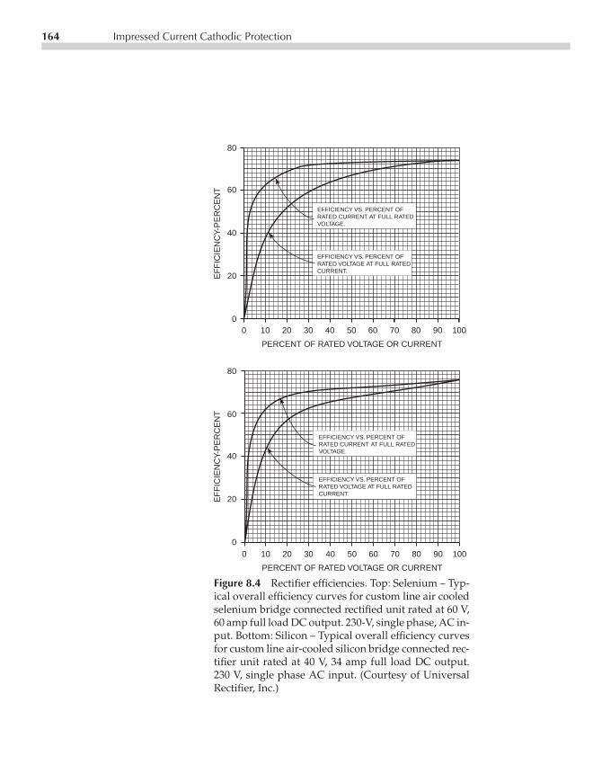
P1: FPVCE003-08 CE003-Peabody November 6, 2000 9:34 Char Count= 0
164 Impressed Current Cathodic Protection
0 10 20 30 40 50 60 70 80 90 100
PERCENT OF RATED VOLTAGE OR CURRENT
80
60
40
20
0
EF
FIC
IEN
CY-
PE
RC
EN
T
0 10 20 30 40 50 60 70 80 90 100
PERCENT OF RATED VOLTAGE OR CURRENT
80
60
40
20
0
EF
FIC
IEN
CY-
PE
RC
EN
TEFFICIENCY VS. PERCENT OFRATED CURRENT AT FULL RATEDVOLTAGE.
EFFICIENCY VS. PERCENT OFRATED VOLTAGE AT FULL RATEDCURRENT.
EFFICIENCY VS. PERCENT OFRATED CURRENT AT FULL RATEDVOLTAGE.
EFFICIENCY VS. PERCENT OFRATED VOLTAGE AT FULL RATEDCURRENT.
Figure 8.4 Rectifier efficiencies. Top: Selenium – Typ-ical overall efficiency curves for custom line air cooledselenium bridge connected rectified unit rated at 60 V,60 amp full load DC output. 230-V, single phase, AC in-put. Bottom: Silicon – Typical overall efficiency curvesfor custom line air-cooled silicon bridge connected rec-tifier unit rated at 40 V, 34 amp full load DC output.230 V, single phase AC input. (Courtesy of UniversalRectifier, Inc.)
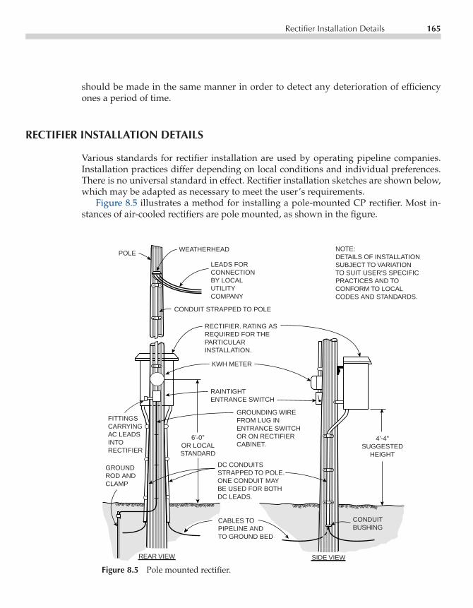
P1: FPVCE003-08 CE003-Peabody November 6, 2000 9:34 Char Count= 0
Rectifier Installation Details 165
should be made in the same manner in order to detect any deterioration of efficiencyones a period of time.
RECTIFIER INSTALLATION DETAILS
Various standards for rectifier installation are used by operating pipeline companies.Installation practices differ depending on local conditions and individual preferences.There is no universal standard in effect. Rectifier installation sketches are shown below,which may be adapted as necessary to meet the user’s requirements.
Figure 8.5 illustrates a method for installing a pole-mounted CP rectifier. Most in-stances of air-cooled rectifiers are pole mounted, as shown in the figure.
POLE WEATHERHEAD
LEADS FORCONNECTIONBY LOCALUTILITYCOMPANY
CONDUIT STRAPPED TO POLE
RECTIFIER. RATING ASREQUIRED FOR THEPARTICULARINSTALLATION.
KWH METER
RAINTIGHTENTRANCE SWITCH
GROUNDING WIREFROM LUG INENTRANCE SWITCHOR ON RECTIFIERCABINET.
6'-0"OR LOCALSTANDARD
DC CONDUITSSTRAPPED TO POLE.ONE CONDUIT MAYBE USED FOR BOTHDC LEADS.
CABLES TOPIPELINE ANDTO GROUND BED
CONDUITBUSHING
4'-4"SUGGESTED
HEIGHT
NOTE:DETAILS OF INSTALLATIONSUBJECT TO VARIATIONTO SUIT USER'S SPECIFICPRACTICES AND TOCONFORM TO LOCALCODES AND STANDARDS.
FITTINGSCARRYINGAC LEADSINTORECTIFIER
GROUNDROD AND CLAMP
REAR VIEW SIDE VIEW
Figure 8.5 Pole mounted rectifier.

P1: FPVCE003-08 CE003-Peabody November 6, 2000 9:34 Char Count= 0
166 Impressed Current Cathodic Protection
GROUND RODPIPELINE
CONCRETEMOUNTING PAD
POWER SUPPLY LINE
TOGROUND-BED
JUNCTIONBOX. OUTPUTVOLTMETERAND AMMETER
COVER MUST BEREMOVED TOCHANGE TAPS
POWER SWITCH
OIL-IMMERSEDRECTIFIER
Figure 8.6 Pad mounted rectifier.
Figure 8.6 shows the use of a concrete pad for mounting air-cooled (pedestal type),oil-filled and explosion-proof rectifiers. Neither of these figures represents an attemptto standardize rectifier installation practices. They are included only to serve as a guideto those who may be preparing installation standards that apply to their own specificsystem requirements.
GROUND BED MATERIALS FOR IMPRESSED CURRENT SYSTEMS
This section includes guidance on the selection of materials for use with impressedcurrent ground beds.
Anode Types
Materials currently popular for use as anode material include graphite, high silicon castiron, mixed metal oxide, platinum, and steel.
Graphite anodes may be obtained in various sizes (Figure 8.7), although 3-in. diam-eters by 60-in. rods are most commonly used for pipeline ground beds. These anodesare typically supplied by the manufacturers with insulated copper leads usually highmolecular weight polyethylene (HMW/PE). Standard lead length and size usually is

P1: FPVCE003-08 CE003-Peabody November 6, 2000 9:34 Char Count= 0
Ground Bed Materials for Impressed Current Systems 167
Figure 8.7 Graphite anodes typical sizes and chemi-cal composition. (Corrpro Companies Inc.)
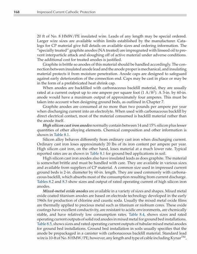
P1: FPVCE003-08 CE003-Peabody November 6, 2000 9:34 Char Count= 0
168 Impressed Current Cathodic Protection
20 ft of No. 8 HMW/PE insulated wire. Leads of any length may be special ordered.Larger wire sizes are available within limits established by the manufacturer. Cata-logs for CP material give full details on available sizes and ordering information. The“specially treated” graphite anodes (NA treated) are impregnated with linseed oil to pre-vent interparticle attack and sloughing off of active material under adverse conditions.The additional cost for treated anodes is justified.
Graphite is brittle so anodes of this material should be handled accordingly. The con-nection between insulated anode lead and the anode proper is mechanical, and insulatingmaterial protects it from moisture penetration. Anode caps are designed to safeguardagainst early deterioration of the connection end. Caps may be cast in place or may bein the form of a prefabricated heat shrink cap.
When anodes are backfilled with carbonaceous backfill material, they are usuallyrated at a current output up to one ampere per square foot (1 A/ft2). A 3-in. by 60-in.anode would have a maximum output of approximately four amperes. This must betaken into account when designing ground beds, as outlined in Chapter 7.
Graphite anodes are consumed at no more than two pounds per ampere per yearwhen discharging current into an electrolyte. When used with carbonaceous backfill bydirect electrical contact, most of the material consumed is backfill material rather thanthe anode itself.
High silicon cast iron anodes normally contain between 14 and 15% silicon plus lesserquantities of other alloying elements. Chemical composition and other information isshown in Table 8.1.
Silicon alloy behaves differently from ordinary cast iron when discharging current.Ordinary cast iron loses approximately 20 lbs of its iron content per ampere per year.High silicon cast iron, on the other hand, loses material at a much lower rate. Typicalreported rates are as shown in Table 8.1 for ground bed applications in soil.
High silicon cast iron anodes also have insulated leads as does graphite. The materialis somewhat brittle and must be handled with care. They are available in various sizesand available from suppliers of CP material. A common size used in impressed currentground beds is 2-in. diameter by 60-in. length. They are used commonly with carbona-ceous backfill, which absorbs most of the consumption resulting from current discharge.Tables 8.2 and 8.3 show sizes and output of rated operating current of high silicon ironanodes.
Mixed-metal oxide anodes are available in a variety of sizes and shapes. Mixed metaloxide coated titanium anodes are based on electrode technology developed in the early1960s for production of chlorine and caustic soda. Usually the mixed metal oxide filmsare thermally applied to precious metal such as titanium or niobium cores. These oxidecoatings have excellent conductivity, are resistant to acidic environments, are chemicallystable, and have relatively low consumption rates. Table 8.4, shows sizes and ratedoperating current outputs of solid rod anodes in mixed metal for ground bed installations.Table 8.5, shows sizes and rated operating current outputs of tubular mixed metal anodesfor ground bed installations. Ground bed installation in soils usually specifies that theanode be prepackaged in a canister with carbonaceous backfill material. Standard leadwire is 10-ft of No. 8 HMW/PE; however, any length and type of cable including KynarTM,
P1: FPVCE003-08 CE003-Peabody November 6, 2000 9:34 Char Count= 0
Ground Bed Materials for Impressed Current Systems 169
Table 8.1 High Silicon Cast Iron Typical Types and Chemical Composition. (CorrproCompanies Inc.)
HalarTM, and PVC can be specified. Mixed metal oxide anodes can also be configuredfor use in deep well anode beds.
Platinum and platinized-niobium anodes are available in a variety of sizes andshapes. Platinum anodes are available in wire and rod configurations and in different

P1: FPVCE003-08 CE003-Peabody November 6, 2000 9:34 Char Count= 0
Table 8.2 Standard High Silicon Cast Iron Anodes. (Corrpro Companies Inc.)
TYPE SIZEIn (mm)
AREAft2(m2) GENERAL APPLICATION SPECIAL FEATURES
B 1 × 60 (25 × 1524) 12 (5.4) 1.4 (.13)
C 11/2 × 60 (38 × 1524) 25 (11.4) 2.0 (.19)
CD 11/2 × 60 (38 × 1524) 26 (11.8) 2.0 (.19)
CDD 11/2 × 60 (38 × 1524) 26 (11.8) 2.0 (.19)
D 2 × 60 (51 × 1524) 44 (20.0) 2.6 (.24)
M 21/4 × 60 (57 × 1524) 63 (28.6) 2.9 (.28)
M1 21/4 × 60 (57 × 1524) 65 (29.5) 2.9 (.27)
E 3 × 60 (76 × 1524) 110 (49.9) 4.0 (.37)
EWO 3 × 60 (76 × 1524) 110 (49.9) 4.0 (.37)
SM 41/2 × 60 (114 × 1524) 220 (99.9) 5.5 (.51)
Fresh water tanks.
Open box coolers requiringlengths greater than 5 feet.
Ground bed with backfill.
Ground bed with backfill permitsjoining in series.
Ground bed without backfill.
Mild saline or deep well withoutbackfill.
Mild saline or deep wellwithout backfill.
Severe ground, deep well or seawater without backfill.
Severe ground, deep well or seawater without backfill.
Sea water with high currentdischarge per anode.
Each end enlarged to 11/2 in. (38 mm)dia. with cored opening for joining.
Uniform 11/2 in. (38 mm) dia. withcored opening both ends for joining.
One end only enlarged to 2 in. (51mm) dia. with cored opening for cable connection.Each end enlarged to 2 in. (51 mm)dia. with cored opening for cableconnection.
Uniform 2 in. (51 mm) dia. with cableconnections on one end only.
Each end enlarged to 3 in. (76 mm)with cored opening for joining.
Same as type M but cored openingon one end only for cableconnection.
One end only enlarged to 4 in. (102mm) dia. with cored opening forcable connection.
One end only enlarged to 4 in. (102mm) dia. with cored opening forcable connection.
Uniform 41/2 in. (114 mm) dia. withcored opening each end. Permits twocable connections, if required.
APPROXIMATEWEIGHT EACH
lbs (kg)
D-51 STANDARD ANODES(Continued)
170
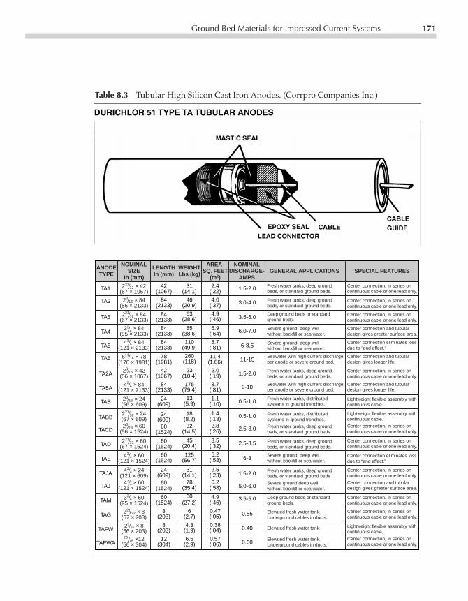
P1: FPVCE003-08 CE003-Peabody November 6, 2000 9:34 Char Count= 0
Ground Bed Materials for Impressed Current Systems 171
Table 8.3 Tubular High Silicon Cast Iron Anodes. (Corrpro Companies Inc.)
TA1
TA2
TA3
TA4
TA5
TA6
TA2A
TA5A
TAB
TABB
TACD
TAD
TAE
TAJA
TAJ
TAM
TAG
TAFW
TAFWA
221/32 × 42(67 × 1067)
23/16 × 84(56 × 2133)
221/32 × 84(67 × 2133)
33/4 × 84(95 × 2133)
43/4 × 84(121 × 2133)
611/16 × 78(170 × 1981)
23/16 × 42(56 × 1067)
43/4 × 84(121 × 2133)
23/16 × 24(56 × 609)
221/32 × 24(67 × 609)23/16 × 60
(56 × 1524)
221/32 × 60(67 × 1524)
43/4 × 60(121 × 1524)
43/4 × 24(121 × 609)
43/4 × 60(121 × 1524)
33/4 × 60(95 × 1524)
221/32 × 8(67 × 203)
23/16 × 8(56 × 203)
23/16 ×12(56 × 304)
42(1067)
84(2133)
84(2133)
84(2133)
84(2133)
78(1981)
42(1067)
84(2133)
24(609)
24(609)
60(1524)
60(1524)
60(1524)
24(609)
60(1524)
60(1524)
8(203)
8(203)
12(304)
2.4(.22)
4.0(.37)
4.9(.46)
6.9(.64)
8.7(.81)
11.4(1.06)
2.0(.19)
8.7(.81)
1.1(.10)
1.4(.13)2.8
(.26)
3.5(.32)
6.2(.58)
2.5(.23)6.2
(.58)
4.9(.46)
0.47(.05)
0.38(.04)
0.57(.06)
31(14.1)
46(20.9)
63(28.6)
85(38.6)
110(49.9)
260(118)
23(10.4)
175(79.4)
13(5.9)
18(8.2)32
(14.5)
45(20.4)
125(56.7)
31(14.1)
78(35.4)
60(27.2)
6(2.7)
4.3(1.9)
6.5(2.9)
1.5-2.0
3.0-4.0
3.5-5.0
6.0-7.0
6-8.5
11-15
1.5-2.0
9-10
0.5-1.0
0.5-1.0
2.5-3.0
2.5-3.5
6-8
1.5-2.0
5.0-6.0
3.5-5.0
0.55
0.40
0.60
Fresh water tanks, deep groundbeds, or standard ground beds.
Fresh water tanks, deep groundbeds, or standard ground beds.
Deep ground beds or standardground beds.
Severe ground, deep wellwithout backfill or sea water.
Severe ground, deep wellwithout backfill or sea water.
Seawater with high current dischargeper anode or severe ground bed.
Fresh water tanks, deep groundbeds, or standard ground beds.
Seawater with high current dischargeper anode or severe ground bed.
Fresh water tanks, distributedsystems in ground trenches.
Fresh water tanks, distributedsystems in ground trenches.
Fresh water tanks, deep groundbeds, or standard ground beds.
Fresh water tanks, deep groundbeds, or standard ground beds.
Severe ground, deep wellwithout backfill or sea water.
Fresh water tanks, deep groundbeds, or standard ground beds.
Severe ground,deep wellwithout backfill or sea water.
Deep ground beds or standardground beds.
Elevated fresh water tank.Underground cables in ducts.
Elevated fresh water tank.
Elevated fresh water tank.Underground cables in ducts.
Center connection, in series oncontinuous cable or one lead only.
Center connection, in series oncontinuous cable or one lead only.
Center connection, in series oncontinuous cable or one lead only.
Center connection and tubulardesign gives greater surface area.
Center connection eliminates lossdue to "end effect."
Center connection and tubulardesign gives longer life.
Center connection, in series oncontinuous cable or one lead only.
Center connection and tubulardesign gives longer life.
Lightweight flexible assembly withcontinuous cable.
Lightweight flexible assembly with continuous cable.
Center connection, in series on continuous cable or one lead only.
Center connection, in series on continuous cable or one lead only.
Center connection eliminates lossdue to “end effect.”
Center connection, in series oncontinuous cable or one lead only.
Center connection and tubulardesign gives greater surface area.
Center connection, in series oncontinuous cable or one lead only.
Center connection, in series oncontinuous cable or one lead only.
Lightweight flexible assembly withcontinuous cable.
Center connection, in series oncontinuous cable or one lead only.
ANODETYPE
NOMINALSIZE
In (mm)
AREA-SQ. FEET
(m2)
NOMINALDISCHARGE-
AMPS
LENGTHIn (mm)
WEIGHTLbs (kg) GENERAL APPLICATIONS SPECIAL FEATURES

P1: FPVCE003-08 CE003-Peabody November 6, 2000 9:34 Char Count= 0
172 Impressed Current Cathodic Protection
Table 8.4 Typical Sizes and Rated Operating Current Data. SolidMixed Metal Oxide Anodes. (Corrpro Companies Inc.)
platinum coating thickness. Table 8.6 shows typical chemical composition of platinumanodes.
Typically the anode is composed of a copper core surrounded by a niobium substratewith the platinum metallurgically bonded to the niobium substrate. The consumption ofthe platinum coating is extremely low (40 to 80 mg/A-year). To achieve the desired designlife of the anode the platinum coating thickness can be varied. Typical platinum coatingthicknesses are 25, 50 and 100 micro-in. Typical practice for ground bed installation insoils is to specify the anode in a prepackage canister with carbonaceous backfill material.Standard lead wire is 10-ft of No. 8 HMW/PE, however any length and type of cableincluding Kynar, Halar and PVC can be specified. Platinum anodes can also be configuredfor use in deep well anode beds.

P1: FPVCE003-08 CE003-Peabody November 6, 2000 9:34 Char Count= 0
Ground Bed Materials for Impressed Current Systems 173
Table 8.5 Sizes and Rated Operating Current Data Tubular.Mixed Metal Oxide Anodes. (Corrpro Companies Inc.)
Table 8.6 Chemical Composition of Platinum Anodes
Element Content % of Diameter
Copper 79.5Niobium 19.5Platinum Less than 1%

P1: FPVCE003-08 CE003-Peabody November 6, 2000 9:34 Char Count= 0
174 Impressed Current Cathodic Protection
Table 8.7 Chemical Composition of Petroleum andMetallurgical Coke Backfill
Element Content %
Petroleum Coke Backfill
Fixed Carbon 99.77Ash 0.1Moisture 0.0Volatile Matter 0.0
Metallurgical Grade
Fixed Carbon 85.89Ash 8–10Moisture 6–9Sulfur 0.8Volatile Matter 0.5
Backfill Materials
The term “carbonaceous backfill” used earlier describes the backfill surrounding groundbed anodes. There are three common materials that fit this description: Coal coke breeze,calcined petroleum coke breeze, and natural or man-made graphite particles. Chemicalcomposition for petroleum coke backfill and metallurgical grade coke backfill are listedin Table 8.7.
All are basically carbon in a low resistivity form. “Breeze” is a loose term indicatinga finely divided material. Originally it referred to the fine screenings left over after coalcoke was graded for sale as fuel. For backfill purposes, however, specific particle sizesmay be obtained.
Carbonaceous backfill serves two purposes when surrounding impressed currentanodes:
• To increase the size of the anode to obtain lower resistance to earth and• To bear the consumption resulting from current discharge.
The latter function requires good electrical contact between the anode and back-fill particles. To accomplish this, the backfill must be tamped solidly around the core.Occasionally, subsurface soil conditions may not allow adequate contact pressure, ormay relax with time, so that much of the current will discharge directly from anode toelectrolyte. This tends to reduce anode life.
Consumption rate of the backfill should not exceed two pounds per ampere per year.In the absence of specific information on the unit weight of the material used, weightsmay be estimated by using the tabulation in Table 8.8. The suppliers can provide specificinformation on coke breeze material.
Coke breeze should be procured by specification. Size and resistivity are important.Some users specify, as an example, that maximum particle size shall not exceed 3/8 in.,

P1: FPVCE003-08 CE003-Peabody November 6, 2000 9:34 Char Count= 0
Ground Bed Materials for Impressed Current Systems 175
Table 8.8 Weights of Carbonaceous Backfill
Material Lb/Ft3
Coal coke breeze. . . . . . . . . . . . . 40 to 50Calcined petroleum coke breeze. . . 45 to 70Natural graphite particles. . . . . . . 70 to 80Crushed man-made graphite. . . . . 70
that not more than 10% dust shall be included and that resistivity shall not exceed50 ohm-cm. Petroleum coke must be calcined (heat treated) to remove all other petroleumproducts; otherwise its resistivity will be too high.
Natural or manufactured graphite both have low resistivity. Although naturalgraphite is available in flake form, flakes are not desirable for ground bed used where gasmust be vented, because the interleaving flakes may block discharge. This applies par-ticularly to deep-well ground beds. Natural graphite may be obtained in granular form(less expensive than flake graphite) and would involve less possibility of gas blockingdifficulties.
Deep-well anode ground beds have reported good results when a calcined petroleumcoke in the form of rounded granules or beads is used. With material of this type, therewill be little interlocking of particles to block passage of gas.
Cable Types
All underground cable, which is a part of an impressed current ground bed, is at a positivepotential with respect to ground. If not perfectly insulated, the cable will dischargecurrent and corrode in two, thus cutting off the current from all or part of the groundbed. Thus first quality insulation must be used on all anode leads and ground bed headercables.
Insulation should have at least a 600-V rating and be suitable for direct burial. Wirewith a high molecular weight polyethylene (HMW/PE) insulation is widely used forground bed construction. This has been effective in most cases. Polyethylene may beused with or without a protective jacket. Where chlorine gas may be generated due toground bed operation or severe chemical environments may be encountered, a protectivejacket of KYNARTM or HALARTM may be necessary.
Cable should be inspected carefully during installation to be absolutely sure thatthere are no scars or cuts which may present problems later. Any scars or cuts in theinsulation must be encapsulated with a heat shrink sleeve. Select only backfill free ofsharp stones or other harmful materials to contact the ground bed cable.
Catalog information on cable suited for ground bed construction is available throughmanufacturers and through suppliers of CP material.
Selecting cable size has both a practical and an economic aspect. From the practi-cal standpoint, the cable should be large enough to carry the intended current (see the

P1: FPVCE003-08 CE003-Peabody November 6, 2000 9:34 Char Count= 0
176 Impressed Current Cathodic Protection
National Electric Code for tables of current rating) and to withstand mechanical stressesencountered during ground bed construction. Cable smaller than No. 8, for impressedcurrent anode cable is not adequate. Anodes should never be installed by the cable. Sim-ilarly, cable that is unusually large may cause handling and connection problems duringconstruction. From the economic standpoint, select a cable size based on a comparison ofcable cost with current carrying ability and the cost of power loss from cable resistancewhen current flows through it.
Connections
Electrical connections between anode leads and header cable are a critical part of im-pressed current ground bed construction. Anode leads must be connected to the headercable by a method that will have permanently low resistance. The connection, oncemade, must be insulated so that it will be waterproof to present current leakage andcable corrosion.
Acceptable connection methods for copper wire include soft soldering, powder weld-ing (thermite), hard (silver) soldering, phos-copper brazing, compression (crimp type)couplings, and split-bolt couplings. The first four methods result in complete joiningof the metals and have permanent low resistance. Mechanical methods, if used prop-erly, also will give low resistance connections, which will remain low if subsequent jointinsulation excludes moisture and air completely so that no corrosion films may formwithin the joint to introduce resistance. When using joining methods involving the useof a torch, cable insulation adjacent to the connection should be protected against heatdamage. Any heat damage should be removed prior to insulating the connection.
Joints should be insulated with materials and methods that will equal, at least, theelectrical strength of original cable insulation. The work must be done carefully so thatinsulation covers all exposed metal and overlaps cable insulation by at least 1 in. Wherejacketed cable is used, the jacket should be removed from about the first 1
2 in. to exposethe basic cable insulation, and then the applied joint insulation will adhere to both cableinsulation and jacket material.
Acceptable joint insulation includes cast epoxy resin insulation and various tapes.There are several manufacturers of cast joint for CP uses. These materials use a contain-ment mold designed to surround the joint to be coated. Then the mold is filled with acatalyzed resin which sets quickly to form a solid cast around the joint and overlappingwire insulation. Properly made, the poured material fills all crevices of the joint to excludemoisture and air. Such connections are recommended particularly for mechanical jointsbut are used also with other types. Satisfactory taped joint insulation can be achievedwith top quality high voltage rubber splicing compound covering the joint metal andoverlapping the wire insulation. This is followed by two half-lapped layers of rubbertape followed by two half-lapped layers of plastic tape. Sharp points or corners shouldbe removed from joints to be taped. If they cannot be rounded sufficiently to preventtape rupture or puncture, they may be padded with electrical putty. Details of joiningand insulating materials may be obtained from the catalogs of CP material suppliers.The splice connections are usually the weakest link in a ground bed installation.

P1: GKW/SPH P2: GKW/UKS P3: GKW/UKS QC:CE003-09 CE003-Peabody November 9, 2000 14:18 Char Count= 0
Chapter9Cathodic Protectionwith Galvanic Anodes
Ronald L. Bianchetti
Discussion of the common types of galvanic (sacrificial) anode materials includingperformance characteristics, typical applications, and installation details are outlinedbelow.
TYPES OF GALVANIC ANODES FOR PIPELINE USE
The two galvanic anode metals commonly used for buried pipelines are magnesiumand zinc. Appearance of typical anodes is shown in Figures 9.1 and 9.2. Aluminum hasa theoretical energy content (in terms of ampere-hours per pound) which exceeds thatof magnesium and zinc but so far, aluminum has not proved practical for earth-buriedinstallations because of problems associated with keeping it electrically active with goodefficiency characteristics. Aluminum anodes are primarily used for marine applicationsbut this specialized application will not be considered here.
HOW GALVANIC ANODES WORK
The use of galvanic anodes for cathodic protection (CP) is a simple application of thedissimilar metal corrosion cell discussed in Chapter 1. Where a steel pipeline is elec-trically connected to a metal higher in the electromotive force series and both are in acommon conductive electrolyte such as the earth, the more active metal is corroded anddischarges current in the process. Magnesium and zinc are such metals. If the amount
177

P1: GKW/SPH P2: GKW/UKS P3: GKW/UKS QC:CE003-09 CE003-Peabody November 9, 2000 14:18 Char Count= 0
178 Cathodic Protection with Galvanic Anodes
Figure 9.1 Typical zinc anodes. (Corrpro Companies Inc.)
of current needed for a given CP application is known, anode systems can be designedusing sufficient anode material to produce the desired current output continuously overa desired number of years.
The corrosive nature of the underground environment may cause self-corrosion ofthe anode material. Electrical currents produced by this self-corrosion do not result inproducing CP current. The ratio of metal expended in producing useful CP current tototal metal expended is termed ‘anode efficiency’. This is an important characteristic,which will be discussed in more detail in the following sections.

P1: GKW/SPH P2: GKW/UKS P3: GKW/UKS QC:CE003-09 CE003-Peabody November 9, 2000 14:18 Char Count= 0
Galvanic Anode Applications 179
Figure 9.2 Typical magnesium anodes. (Corrpro Com-panies Inc.)
GALVANIC ANODE APPLICATIONS
For pipeline CP applications, galvanic anodes are generally used in cases where relativelysmall amounts of current are required (typically less than 1 A) and areas where soilresistivity is low enough (typically less than 10,000 ohm-cm) to permit obtaining thedesired current with a reasonable number of anodes. If large amounts of current areneeded (typically greater than 1 A) impressed current systems tend to be more economi-cal. If there is a question as to which current source to use, an economic analysis shouldbe undertaken, unless local conditions dictate otherwise. Chapter 15 provides the basisfor performing economic analyses.

P1: GKW/SPH P2: GKW/UKS P3: GKW/UKS QC:CE003-09 CE003-Peabody November 9, 2000 14:18 Char Count= 0
180 Cathodic Protection with Galvanic Anodes
Short increments of well-coated pipe will have moderate current requirements forprotection. These current requirements can be met with galvanic anodes where soil resis-tivity conditions are suitable.
Some operators follow a practice of installing galvanic anodes at each location wherea leak is repaired (hot spot protection) rather than installing a complete CP system. Suchpractices may be encountered on bare or very poorly coated systems where completeCP may not be feasible from an economic standpoint.
On well-coated pipelines with impressed current CP systems, there may be isolatedpoints where additional current may be needed in relatively small amounts. These re-quirements can be met with galvanic anodes. Typical applications include poorly orincompletely coated buried valve installations, shorted casings which cannot be cleared,isolated sections where pipeline coating has been badly damaged and areas where electri-cal shielding may impair effective current distribution from remotely located impressedcurrent systems.
Galvanic anodes may be used in some instances to correct stray current interferenceconditions at pipeline crossings where the interference arises from impressed current CPsystems. This application is discussed further in Chapter 11.
Galvanic anodes (usually zinc) may also be used for electrical grounding applica-tions at pipeline pumping stations and across insulating joints. Zinc anodes as groundrods serve as effective electrical grounds and at the same time provide a measureof CP.
Pipelines may pass through areas where there are many other underground metallicstructures under conditions that make it difficult to install impressed current systemswithout creating stray current interference problems (see Chapter 11). Galvanic anodesmay be an economical choice for a CP current source under such conditions.
CHARACTERISTICS OF MAGNESIUM AND ZINC ANODES
Magnesium is the most widely used material for galvanic anodes. Typical characteristicsare given in Table 9.1. Magnesium anodes are available in various shapes and weightsfrom the manufacturers. Some of the sizes available, suitable for use in soil, are listed inTable 9.2.
Zinc anodes are available in a number of sizes for use in earth anode beds. Typicalcharacteristics of zinc used as an anode material are given in Table 9.3. These are longslender shapes to achieve low resistances to earth and practical current output at theusual low driving voltage between anode and protected structure. Some sizes availableas standard commercial items are shown in Table 9.4. Nonstandard sizes may be obtainedon special order.
Packaged magnesium and zinc anodes (anode and backfill furnished as a completeunit ready for installation) are standard with most suppliers.

P1: GKW/SPH P2: GKW/UKS P3: GKW/UKS QC:CE003-09 CE003-Peabody November 9, 2000 14:18 Char Count= 0
Characteristics of Magnesium and Zinc Anodes 181
Table 9.1 Characteristics of Magnesium Anodes
Specific Gravity
Pounds per Cubic Foot
Theoretical Amp Hours per Pound
Theoretical Pounds per Amp per Year
Current Efficiency - Percent
Actual Amp Hours per Pound
Actual Pounds per Amp per Year
Solution Potential - Volts to CSE
Standard H-1 Alloy
High Potential Alloy
Driving Potential to Pipeline
Polarized to −0.90 Volt to CuSO4
Standard Alloy - Volts
High Potential Alloy - Volts
1.94
121
1000
8.7
50(2)
500(2)
17.4(2)
−1.50 to −1.55(3)
−1.75 to −1.77(4)
0.55(5)
0.80(5)
Weight Content %Element Grade A Grade B Grade C
Al 5.3 - 6.7 5.3 - 6.7 5.0 - 7.0Mn 0.15 min 0.15 min 0.15 minZn 2.5 - 3.5 2.5 - 3.5 2.0 - 4.0Si 0.10 max 0.30 max
0.05 max
0.30 max
Cu 0.02 max 0.10 max
Ni 0.002 max 0.003 max 0.003 maxFe 0.003 max 0.003 max 0.003 max
Other 0.30 max 0.30 max 0.30 maxMagnesium Remainder Remainder Remainder
STANDARD H-1 ALLOYCHEMICAL COMPOSITION
Element Weight Content %Al 0.010
Mn 0.50 to 1.30
Cu 0.02 Max
Ni 0.001 Max
Fe 0.03 Max
Other 0.05 each or 0.3 Max Total
Magnesium Remainder
HIGH POTENTIAL ALLOYCHEMICAL COMPOSITION
(1) Anodes installed in suitable chemical backfill.(2) Current efficiency varies with current density. Efficiency given (which results
in actual amp hr per pound and actual pounds per amp per year shown) is at approximately 30 milliamps per sq ft of anode surface. Efficiencies are higher at higher current densities, lower at lower current densities.
(3) Alloy with nominal composition % 6 Al, 3 Zn, 0.2 Mn and balance Mg.(4) Proprietary alloy−manganese principal alloying element.(5) Driving potentials allow for anode polarization in service of approximately
0.10 volt which reduces the solution potenital by this amount. Driving potential in volts for pipeline polarized to any specific potential (P) in volts = solution potential of magnesium type used minus 0.10 volts minus
Current efficiency varies with current density. Efficiency given (which results in actual amp hr per pound and actual pounds per amp per year shown) is at approximately 30 milliamps per sq ft of anode surface. Efficiencies are higher at higher current densities, lower at lower current densities.
Driving potentials allow for anode polarization in service of approximately 0.10 volt which reduces the solution potential by this amount. Driving potential in volts for pipeline polarized to any specific potential (P) in volts = solution potential of magnesium type used minus 0.10 volts minus P.

P1: GKW/SPH P2: GKW/UKS P3: GKW/UKS QC:CE003-09 CE003-Peabody November 9, 2000 14:18 Char Count= 0
182 Cathodic Protection with Galvanic Anodes
Table 9.2 Magnesium Anode Types (Corrpro Companies Inc.)
PACKAGED ANODE
LEAD WIRE
BACKFILL
CLOTHSACK
20 GAUGE GALV.STEEL CORE
BARE ANODE
Standard Dimensions and Shipping Weights
ANODETYPE
NOMINAL DIMENSIONSin (mm)
"A" "B" "C" "D" "E"
NOMINAL WT.lbs (kg)
BARE PKGD.
3 lb 3 (76) 3 (76) 4.5 (114) 6.5 (165) 6 (152) 3 (1.4) 9 (4.1)
5 lb 3 (76) 3 (76) 7.5 (191) 13.5 (343) 6 (152) 5 (2.3) 14 (6.4)
9 lb 2 (51) 2 (51) 27 (686) 31 (787) 5 (127) 9 (4.1) 36 (16.3)
9 lb 3 (76) 3 (76) 13.5 (343) 17 (432) 6 (152) 9 (4.1) 24 (10.9)
17 lb 2 (51) 2 (51) 51 (1295) 55 (1397) 5 (127) 17 (7.7) 61 (27.7)
17 lb 3 (76) 3 (76) 25.5 (648) 30 (762) 6 (152) 17 (7.7) 42 (19.1)
20 lb 2 (51) 2 (51) 60 (1524) 62.5 (1588) 5 (127) 20 (9.1) 70 (31.8)
32 lb 3 (76) 3 (76) 45 (1143) 61 (1549) 6 (152) 32 (14.5) 90 (40.8)
32 lb 5 (127) 5 (127) 21 (533) 30 (762) 8 (203) 32 (14.5) 70 (31.8)
40 lb 3 (76) 3 (76) 60 (1524) 64 (1626) 6 (152) 40 (18.1) 105 (47.6)
48 lb 5 (127) 5 (127) 31 (787) 34 (864) 8 (203) 48 (21.8) 96 (43.6)
60 lb 4 (102) 4 (102) 60 (1524) 64 (1626) 6.75 (171) 60 (27.2) 130 (59.0)
E
D
C B
A
ANODE
High PotentialCast Magnesium Anodes

P1: GKW/SPH P2: GKW/UKS P3: GKW/UKS QC:CE003-09 CE003-Peabody November 9, 2000 14:18 Char Count= 0
Characteristics of Magnesium and Zinc Anodes 183
Table 9.2 (Continued)
Standard Dimensions and Shipping Weights
ANODETYPE
NOMINAL DIMENSIONSin (mm)
"A" "B" "C" "D" "E"
NOMINAL WT.lbs (kg)
BARE PKGD.
1 lb 2.9 (74) _ 3 (76) 6 (152) 6 (152) 1 (0.45) 3.5 (1.6)
3 lb 3 (76) 3 (76) 4.5 (114) 6.5 (165) 6 (152) 3 (1.4) 9 (4.1)
5 lb 3 (76) 3 (76) 7.5 (191) 13.5 (343) 6 (152) 5 (2.3) 14 (6.4)
9 lb 3 (76) 3 (76) 13.5 (343) 17 (432) 6 (152) 9 (4.1) 24 (10.9)
17 lb 4 (102) 4 (102) 17 (432) 19 (483) 6.5 (165) 17 (7.7) 42 (19.1)
32 lb 5 (127) 5 (127) 21 (533) 30 (762) 8 (203) 32 (14.5) 70 (31.8)
50 lb 8 (203) _ 15 (381) 18 (457) 10 (254) 50 (22.7) 110 (49.9)
PACKAGED ANODE
LEAD WIRE
BACKFILL
CLOTHSACK
20 GAUGE GALV.STEEL CORE
BARE ANODE
E
D
C B
A
ANODE
H-1 AlloyCast Magnesium Anodes
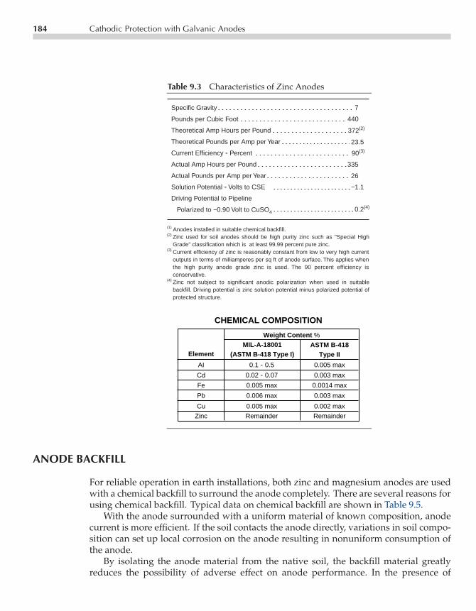
P1: GKW/SPH P2: GKW/UKS P3: GKW/UKS QC:CE003-09 CE003-Peabody November 9, 2000 14:18 Char Count= 0
184 Cathodic Protection with Galvanic Anodes
Table 9.3 Characteristics of Zinc Anodes
Specific Gravity
Pounds per Cubic Foot
Theoretical Amp Hours per Pound
Theoretical Pounds per Amp per Year
Current Efficiency - Percent
Actual Amp Hours per Pound
Actual Pounds per Amp per Year
Solution Potential - Volts to CSE
Driving Potential to Pipeline
Polarized to −0.90 Volt to CuSO4
7
440
372(2)
90(3)
0.2(4)
23.5
335
26
−1.1
Weight Content %
ElementMIL-A-18001
(ASTM B-418 Type I)ASTM B-418
Type II
AI 0.1 - 0.5 0.005 max
Cd 0.02 - 0.07 0.003 max
Fe 0.005 max 0.0014 max
Pb 0.006 max 0.003 max
Cu 0.005 max 0.002 max
Zinc Remainder Remainder
CHEMICAL COMPOSITION
(1) Anodes installed in suitable chemical backfill.(2) Zinc used for soil anodes should be high purity zinc such as "Special High
Grade" classification which is at least 99.99 percent pure zinc.(3) Current efficiency of zinc is reasonably constant from low to very high current
outputs in terms of milliamperes per sq ft of anode surface. This applies when the high purity anode grade zinc is used. The 90 percent efficiency is conservative.
(4) Zinc not subject to significant anodic polarization when used in suitable backfill. Driving potential is zinc solution potential minus polarized potential of protected structure.
Zinc used for soil anodes should be high purity zinc such as "Special High Grade" classification which is at least 99.99 percent pure zinc.Current efficiency of zinc is reasonably constant from low to very high current outputs in terms of milliamperes per sq ft of anode surface. This applies when the high purity anode grade zinc is used. The 90 percent efficiency is conservative.Zinc not subject to significant anodic polarization when used in suitable backfill. Driving potential is zinc solution potential minus polarized potential of protected structure.
ANODE BACKFILL
For reliable operation in earth installations, both zinc and magnesium anodes are usedwith a chemical backfill to surround the anode completely. There are several reasons forusing chemical backfill. Typical data on chemical backfill are shown in Table 9.5.
With the anode surrounded with a uniform material of known composition, anodecurrent is more efficient. If the soil contacts the anode directly, variations in soil compo-sition can set up local corrosion on the anode resulting in nonuniform consumption ofthe anode.
By isolating the anode material from the native soil, the backfill material greatlyreduces the possibility of adverse effect on anode performance. In the presence of

P1: GKW/SPH P2: GKW/UKS P3: GKW/UKS QC:CE003-09 CE003-Peabody November 9, 2000 14:18 Char Count= 0
Table 9.4 Zinc Anode Types
PACKAGED ANODE
ANODELEAD WIRE
BACKFILLCLOTHSACK
20 GAUGE GALV.STEEL CORE
BARE ANODE
RIBON ANODE
Standard Dimensions and Shipping Weights
ANODETYPE
NOMINAL DIMENSIONSin (mm)
NOMINAL WT.lbs (kgs)
"A" "B" "C" "D" "E" BARE PKGD.
SOIL PACKAGED ANODES
5 lb 1.4 (35.5) 1.4 (35.5) 9 (228.6) 15 (381) 5 (127) 5 (2.3) 24 (10.8)
12 lb 1.4 (35.5) 1.4 (35.5) 24 (609.6) 30 (762) 5 (127) 12 (5.4) 48 (21.7)
18 lb 1.4 (35.5) 1.4 (35.5) 36 (914.4) 42 (1066.8) 5 (127) 18 (8.1) 70 (31.7)
30 lb 1.4 (35.5) 1.4 (35.5) 60 (1524) 66 (1676.4) 5 (127) 30 (13.6) 95 (43.0)
30 lb 2 (50.8) 2 (50.8) 30 (762) 36 (914.4) 5 (127) 30 (13.6) 70 (31.7)
45 lb 2 (50.8) 2 (50.8) 45 (1143) 51 (1295.4) 5 (127) 45 (20.4) 110 (49.9)
60 lb 2 (50.8) 2 (50.8) 60 (1524) 66 (1676.4) 5 (127) 60 (27.2) 130 (58.9)
E
D
C B
B
A
A
ANODETYPE
NOMINAL DIMENSIONSBARE WT.lbs/lineal ft
(kg/lineal M)"A" "B" "C"
in (mm) in (mm) ft/RO (M/RO)
RIBBON EXTRUDED ANODES
Super 1 (25.4) 1-1/4 (31.7) 100 (30.4) 2.4
Plus 5/8 (15.8) 7/8 (22.2) 200 (60.9)1.2
Standard 1/2 (12.7) 9/16 (14.2) 500 (152.4) 0.6
Small 11/32 (8.7) 15/32 (11.9) 1,000 (304.7) 0.25
(1.09)
(0.54)
(0.27)
(0.11)
c
1/8" IRON WIRE CORE
* The Standard anode model is also available in 1000 and 3600 foot rolls.
Soil and RibbonCast and Extruded Zinc Anodes
185

P1: GKW/SPH P2: GKW/UKS P3: GKW/UKS QC:CE003-09 CE003-Peabody November 9, 2000 14:18 Char Count= 0
186 Cathodic Protection with Galvanic Anodes
Table 9.5 Backfill data for Magnesium and Zinc Anodes
Gypsum (CaSO4)%
Molding Plaster Bentonite Sodium Approx ResistivityHydrated (Plaster of Paris) Clay % Sulfate % in ohm-cm
(A) 50 – 50 – 250(B) 75 – 20 5 50
1. Backfill mix (A) commonly used with zinc anodes.2. Backfill mix (B), with low resistivity, is useful in high soil resistivity areas to reduce the anode resistance
to earth.
phosphates, carbonates and bicarbonates, zinc anodes can develop passive films andcease to produce useful amounts of current. Carbonates and bicarbonates will influencemagnesium the same way. Chlorides tend to increase self-corrosion of magnesium andreduce its current efficiency.
Chemical backfills can be helpful in absorbing soil moisture to keep the environmentimmediately surrounding the anode continuously moist. Anode backfill is of low resis-tivity and when anodes are installed in soils having a resistivity higher than that of thebackfill, the backfill column has the effect of increasing the anode size. This results in alower resistance to remote earth than would be the case if the bare anode were burieddirectly in the soil. This effect is discussed in Chapter 7.
CALCULATING ANODE LIFE
If current output of a galvanic anode of any given weight is known, its approximateuseful life can be calculated. This calculation is based on the theoretical ampere-hourper pound of the anode material, its current efficiency, and a utilization factor. Theutilization factor may be taken as 85%—meaning that when the anode is 85% consumed,it will require replacement because there is insufficient anode material remaining tomaintain a reasonable percentage of its original current output.
For magnesium, anode life may be determined by the following expression (efficiencyand utilization factor expressed as decimals).
Magnesium Anode
Life (years) = 0.116×Anode Weight (pounds)× Efficiency×Utilization FactorDesign Current (amperes)
.
For zinc anodes, anode life may be determined in similar manner by the followingexpression:

P1: GKW/SPH P2: GKW/UKS P3: GKW/UKS QC:CE003-09 CE003-Peabody November 9, 2000 14:18 Char Count= 0
Calculating Anode Life 187
Zinc Anode
Life (years) = 0.0424×Anode Weight (pounds)× Efficiency×Utilization FactorDesign Current (amperes)
.
As an example, assume that a 32-lb magnesium anode is producing 0.1 A at 50% efficiencyand that a 30-lb zinc anode is producing 0.1 A at 90% efficiency. Compare the expectedoperating lives at the 0.1 A output.
Magnesium Anode Life (years) = 0.116× 32× 0.50× 0.850.1
= 15.8 yr,
Zinc Anode Life (years) = 0.0424× 30× 0.90× 0.850.1
= 9.7 yr.
These calculations reflect the difference in theoretical ampere hours per pound charac-teristic of the two materials. Although anode costs may fluctuate with the metal market,zinc is typically less expensive than magnesium. Graphical design information has beendeveloped for typical anode types. An example is shown in Figure 9.3.
20 30 40 70 100 200 300 400 700 1000
Anode Current (milliamperes)
Soi
l Res
istiv
ity (
ohm
-cm
)
10000
7000
5000
3000
2000
1000
700
500
300
200
High Purity H-1p/s = −0.70 voltsp/s = −0.85 volts
Current expected in varioussoils from a 17 lb. anode, 10ft. from an 8" bare pipeline,at two different pipe-to-soilpotentials.
GALVOMAGp/s = −0.70 voltsp/s = −0.85 volts
Current Output of GALVOMAG®
and High Purity H-1 Anodes.
Figure 9.3 Magnesium anode design curves. (CorrproCompanies Inc.)

P1: GKW/SPH P2: GKW/UKS P3: GKW/UKS QC:CE003-09 CE003-Peabody November 9, 2000 14:18 Char Count= 0
188 Cathodic Protection with Galvanic Anodes
DESIGN CONSIDERATIONS
To provide a better understanding of the differences in performance between zinc andmagnesium installations it may be helpful to first identify typical types of installa-tion practices. A general rule-of-thumb says that zinc anodes are better used in thelower soil resistivity (below 1500 ohm-cm) and magnesium anodes are better in thehigher resistivity soils (between 1500 and 10,000 ohm-cm). This rule is not universaland will depend on the application. This will be illustrated by the examples presentedbelow.
Well-coated pipeline sections typically have low current requirements and will po-larize easily to a volt or more. Either zinc or magnesium anodes may provide sufficientcurrent for full protection, but zinc anodes may provide full protection with much lesscurrent being wasted. This is illustrated in the following example.
Assume a well-coated section of pipeline having a native or static potential to a coppersulfate reference electrode (CSE) of −0.7 V, an effective resistance-to-earth of 2 ohm atthe anode installation site and that 75 mA is necessary to shift the pipeline potential to−0.85 V. Also assume that the soil resistivity at the anode installation site is 1500 ohm-cm.
The installation circuit resistance needed to raise the potential to −0.85 V using zincanodes is calculated by determining the driving voltage (1.1 V − 0.85 V) or 0.25 V anddividing it by the current requirement. This calculation is performed using Ohm’s Law,0.25 V/0.075 A = 3.3 ohms. The calculated 3.3 ohms minus the effective resistance ofthe pipeline, estimated at 2 ohms, leaves 1.3 ohms for the resistance of anodes and leadwires. Following the procedures outlined in Chapter 7, it can be calculated that five1.4 × 1.4 × 60-in zinc anodes (30 lb) surrounded with 50–50 gypsum-bentonite backfillin 8-in diameter holes at 15-ft spacing will have a resistance of 1.21 ohms in the 1500ohm-cm soil. With 0.03 ohms allowed for lead wire resistance, total resistance is 1.24ohms which is within the 1.3-ohm design allowance.
The same procedure can be derived for magnesium anodes. The magnesium in-stallation circuit resistance needed to provide the initial 75 mA requirement will be thedriving potential (1.55− 0.85 = 0.70 V) divided by the estimated current requirement of75 mA, equals 9.33 ohms. Subtracting the 2-ohm pipeline resistance leaves 7.33 ohms foranode-to-earth resistance and lead wire resistance. Using Chapter 7 anode bed resistanceprocedures, one 2 × 2 × 60-in magnesium anode (20 lb each) with 75% gypsum, 20%bentonite, 5% sodium sulfate backfill in 8-in diameter hole will give 4.80 ohms anode-to-earth resistance in the 1500 ohm-cm soil with 0.01 ohm allowed for lead wire resistance.This totals 4.81 ohms, which is within the 7.33-ohm requirement.
As shown in the previous example, the zinc anode installation number of anodes ismuch larger. This is not, however, the complete analysis. In most cases, a well-coatedpipeline will continue to polarize after initial requirements are met. The pipeline in thezinc anode example may polarize to a potential approaching the −1.1 V open circuitpotential of zinc. This will result in the reduced current demand.
Assume a polarized potential of−1.05 volt. The zinc anodes will now have a drivingpotential of only 0.05 V (1.1− 1.05 V) and the current output will be 0.05-V/3.24-ohms

P1: GKW/SPH P2: GKW/UKS P3: GKW/UKS QC:CE003-09 CE003-Peabody November 9, 2000 14:18 Char Count= 0
Design Considerations 189
circuit resistance = 0.0154 A. The magnesium anodes will have a driving potentialof 0.35 V (1.55 − 1.2 V) and the current output will be 0.35 V/6.81-ohms circuitresistance = 0.0513 A. These final or stabilized currents can be used to determine theuseful lives of the two installations.
The five, 30-lb zinc anodes will have calculated life as follows.
Zinc Anode Life (years) = 0.0424× 5(30)× 0.90× 0.850.0154
= 315 yr.
The single 20-lb magnesium anode will have a calculated life as follows:
Magnesium Anode Life (years) = 0.116× 20× 0.50× 0.850.0513
= 19.2 yr.
The new calculated design life for each anode is at the efficiencies shown in the for-mula (90% for zinc, 50% for magnesium). At very low current densities, efficiencies willdecrease and actual lives would be less than indicated. This is particularly true formagnesium anodes.
To evaluate these two installations in terms of cost per year of estimated life, theinstalled cost must be known. Zinc is less expensive than magnesium. Assuming a con-servatively high material and installation cost per anode, the five zinc anodes couldcost $250 per anode to install or $1,250. The one magnesium anode with installationon the same basis could cost $350. The indicated cost per year for the zinc installationwould be $1,250/315 years = $3.96 per year. Similarly, the indicated cost per year forthe magnesium installation would be $350/19.2 years = $18.22 per year.
It may appear that the indicated life of 315 years for the zinc installation is beyondreasonable expectations when the usual design life of a pipeline is 20–50 yr. If the costper year is based on a 20-yr pipeline life, the zinc anode installation cost per year wouldbe $62.50 (although not consumed at the end of this period) while the magnesium costper year remains at approximately $18. This analysis favors magnesium if the estimatedprotection current requirements do not change.
If current requirements increase (see the following discussion on regulation), the orig-inal zinc installation can continue to provide adequate protection, whereas replacementof the magnesium anode would be required in less than 20 yr. The magnesium anodereplacement would require more anodes than were used originally in order to maintainadequate protection. This will bring the cost per year to roughly equivalent figures forzinc and magnesium for the example used in the 1500 ohm-cm soil. Chapter 15 providesmore detailed analysis of life cycle cost.
The previous illustration indicates that on a long-term basis, zinc anode installationscan be less expensive than magnesium when calculated on a simple cost per year basis.In the example, it was shown that one magnesium anode discharged more than twiceas much current as the five zinc anodes. This offers no advantage because zinc fullyprotects the line while excess current from magnesium is wasted.

P1: GKW/SPH P2: GKW/UKS P3: GKW/UKS QC:CE003-09 CE003-Peabody November 9, 2000 14:18 Char Count= 0
190 Cathodic Protection with Galvanic Anodes
Inserting resistance in series in the circuit can control the wasted current from mag-nesium. In the previous example, current wastage can be eliminated if sufficient resis-tance could be inserted in series with the magnesium anode to reduce its output to thepoint that the pipeline would remain protected. That current level would be the sameas that obtained from the zinc anode (0.030 A). The driving potential would now be1.55− 1.05 = 0.4 V. Circuit resistance would be 0.4 V/0.030 A = 13 ohms. This value of13 ohms minus the circuit resistance of the magnesium anode alone, 6.81 ohms (from theexample above), leaves 6.52 ohms resistance to be inserted in the circuit. By reducingthe current, the magnesium anode indicated life is increased to 33 yr, reducing the costper year of life to $10.60, which is more in line with the zinc installation. This is furtherdiscussed below.
ANODE PERFORMANCE
System Regulation
Regulation as applied to galvanic anode installations is a measure of an installations’ability to adjust output automatically to compensate for changes in the current require-ments of the pipeline to which it is attached. In the previous example which compareszinc and magnesium, the assumed pipeline section had an excellent coating, so verylittle current was required to maintain protection. However, current requirements mayincrease with time due to coating deterioration, addition of more pipe, or developmentof a short circuit to another foreign pipeline.
Assuming that this has occurred, the effective resistance of the pipeline to earth atthe anode installation site drops from the original 2 ohms to 0.5 ohms. Also assume theminimum current required to maintain a polarized potential of−0.85 V has increased to130 mA from the original 75 mA. Using figures from the preceding example:
Zinc installation
• Driving potential = 1.1− .85 = 0.25 V• New circuit resistance = 1.74• Current = 0.25/1.74 = 0.144 A (144 mA)• Indicated life at 144 mA output = 33.6 yr
Magnesium installation without current reducing resistor
• Driving potential = 1.55− .85 = 0.70 V• New circuit resistance = 5.31 ohm• Current = 0.7/5.31 = 0.188 A (188 mA)• Indicated life at 188 mA output = 8.4 yr

P1: GKW/SPH P2: GKW/UKS P3: GKW/UKS QC:CE003-09 CE003-Peabody November 9, 2000 14:18 Char Count= 0
Anode Performance 191
Magnesium installation with current reducing resistor
• Driving potential = 0.70 V• New circuit resistance = 24.5 ohms• Current = 0.7/24.5 = 0.0285 A (28.5 mA)• Indicated life at 28.5 mA output = 55 yr
In this example, the zinc installation has a greater capability of providing current thanthe minimum required, indicating that the line will polarize to some value above the−0.85 V minimum protection value and that consequently there will be a better distri-bution of full protective potentials along the line. The magnesium installation withoutresistor (which originally discharged more than twice as much current as the zinc andwas wasting current) now does not discharge quite enough current to maintain the min-imum −0.85 V. The line will assume a potential of something less than −0.85 V. Themagnesium installation with a current controlling resistor obviously does not dischargeenough current. The size of the resistor would need to be reduced below the calculated6.5 ohms value from above or the resistor would have to be removed to achieve any sub-stantial degree of protection. This would then reduce the design life of the magnesiumanode.
Variations in Soil Resistivity
The relative effect of soil resistivity on anode performance is discussed below. Calcula-tions for zinc and magnesium anodes in soils ranging from low to high resistivity aresummarized in Table 9.6. The conditions applicable to Table 9.6 are the same as forthe preceding example based on an installation in 1500 ohm-cm soil (the 1500 ohm-cmfigures summarize those developed in the example). Specifically, assumptions are thefollowing.
1. That the pipeline section being protected is well coated and that it has an effectiveresistance to earth of 2 ohms.
2. That 75 mA are required initially to polarize the pipeline to−0.85 V to copper sulfate.3. That once CP current is applied, the line will continue to polarize to −1.05 V CSE
when protected with zinc and to −1.2 V when protected with magnesium.
Anodes of similar sizes were used for both magnesium and zinc for purposes of this com-parison. If more than one anode was required, the anode bed resistance was calculatedon the basis of 15-ft spacing between anodes.
Although the use of different anode sizes would alter the current output and indicatedlife, the table does illustrate certain tendencies. These are the following.
1. That zinc anode installations of the smallest size that will meet design current require-ments have a substantially longer life than their magnesium anode counterparts.

P1: GKW/SPH P2: GKW/UKS P3: GKW/UKS QC:CE003-09 CE003-Peabody November 9, 2000 14:18 Char Count= 0
192 Cathodic Protection with Galvanic Anodes
Table 9.6 Comparison of Zinc and Magnesium Anodes in Varying Resistivities
Soi
l Res
istiv
ityin
ohm
-cm
Ano
de T
ype
Driv
ing
Pot
entia
l in
volts
with
Pip
elin
e P
olar
ized
to −
0.85
V
Max
P
erm
issi
ble
Res
ista
nce
of
Ano
des
and
Lead
s, in
ohm
s, w
ith
2 oh
ms
Pip
e -to
-Ear
th R
esis
tanc
e
Num
ber,
Siz
e (in
Inc
hes)
and
Wei
ght
(Eac
h) o
f Ano
des
Sel
ecte
d
Res
ista
nce
of A
node
Arr
ay S
elec
ted
in o
hms
Act
ual T
otal
Circ
uit R
esis
tanc
e in
oh
ms
Act
ual
Cur
rent
in
mA
with
Pip
elin
e P
olar
ized
to
−1.0
5 V
with
zin
c or
to
−1.2
0 V
with
Mg
Indi
cate
d A
node
Life
in Y
ears
Max
Cur
rent
, m
A,
with
Pip
e-to
-E
arth
Res
ista
nce
Dro
pped
to 0
.50
ohm
and
with
−0.
85 V
Pol
ariz
ed
Reg
ulat
ion
as R
atio
of M
axim
um
Cur
rent
to th
at U
nder
Initi
al
Con
ditio
ns
Indi
cate
d A
node
Life
in Y
ears
Und
er
Max
imum
Cur
rent
Con
ditio
ns
Mag 0.6 8.0 6.0 1.44 3.44 72.8 27.2 403 5.55 4.9
Zinc 0.25 3.3 1.3 0.76 2.76 18.1 107 198 11.0 9.8
Mag 0.6 8.0 6.0 2.0 4.0 62.5 31.5 240 3.85 8.2
Zinc 0.25 3.3 1.3 1.07 3.07 16.2 120 159.5 9.85 12.2
Mag 0.6 8.0 6.0 4.81 6.81 36.6 26.9 113 3.08 8.7
Zinc 0.25 3.3 1.3 1.24 3.24 15.4 315 144 9.35 33.6
Mag 0.6 8.0 6.0 4.86 6.86 36.4 55.2 112 3.08 17.6
Zinc 0.25 3.3 1.3 1.3 3.3 15.2 745 139 9.15 83
One3 × 3 × 6040-Pound
Two1.4 × 1.4 × 60
30-Pound
Two1.4 × 1.4 × 60
30-Pound
Five1.4 × 1.4 × 60
30-Pound
Eleven1.4 × 1.4 × 60
30-Pound
One3 × 3 × 6040-Pound
One2 × 2 × 6020-Pound
Two2 × 2 × 6020-Pound
300
500
1500
3000
Max
imum
Per
mis
sibl
e C
ircu
it R
esis
tanc
e in
ohm
s, fo
r 75
mA
2. That as soil resistivity increases, the ratio of number of zinc anodes to the numberof magnesium anodes increases. This increases installation costs for zinc at a greaterrate than for magnesium.
3. That magnesium anode current outputs are consistently higher than the output ofthe zinc anodes under design conditions. This represents wasted current from themagnesium anodes because fully adequate protection is obtained from zinc at itslower current output.

P1: GKW/SPH P2: GKW/UKS P3: GKW/UKS QC:CE003-09 CE003-Peabody November 9, 2000 14:18 Char Count= 0
Galvanic Anode Installation Details 193
4. That if the current demands of the pipeline increase, the magnesium anodes in lowresistivity soil will continue to deliver higher currents than zinc anodes. Under lowersoil resistivity conditions, more magnesium anode material (using anodes of thesize shown) would be needed to obtain equivalent life than would be needed usingzinc.
5. That if the current demands of the pipeline increase, zinc anode installations in thehigher resistivity soils have a higher current delivery capability than the magnesiuminstallations.
6. That the gains by regulation of zinc installations are consistently better than thosefrom magnesium and that the ratio of the two increases as soil resistivity increases.This characteristic is related closely to observations 4 and 5.
The conclusions that can be reached from the foregoing examples and comparisonsinclude the following.
1. That installations may be designed using either zinc or magnesium over a wide rangeof soil resistivities.
2. That from an economic standpoint, zinc is most attractive in lower resistivity soils.Using it in soils below 1500 ohm-cm resistivity is a reasonable guide in this respect.
3. That zinc anodes in soils of any resistivity offer the best self-regulating characteristicsin terms of continuing to provide sufficient current for adequate protection withoutexcessive current wastage.
GALVANIC ANODE INSTALLATION DETAILS
Galvanic anode installations are simple compared to the usual impressed current instal-lation. The simplest installation is that involving the burying of a single packaged anodeat a leak repair location or for distributed anode installations along a pipeline. This isshown by Figure 9.4.
The popular 17-lb, 20-lb, or 32-lb packaged magnesium anodes are used most com-monly for this type of application, although packaged zinc anodes may be used in lowresistivity soils and heavier packaged magnesium anodes may be used, where conditionswarrant, for longer life.
Where several magnesium or zinc anodes are to be installed at a single location,usually on a coated pipeline, the anodes may be connected to a header wire. The headerwire should be brought to a test point to permit monitoring, and periodic measurementof output current, for calculation of anode life. This is illustrated by Figure 9.5.
Anodes in a multiple anode bed should be placed in straight line configuration forlowest resistance to earth. The line of anodes may be perpendicular to the pipeline, asshown in the figure, or may be along a line parallel to the pipe. The latter arrangementmakes it possible, in many cases, to install a large galvanic anode bed without having togo beyond the limits of the pipeline right-of-way. A parallel line of magnesium anodes
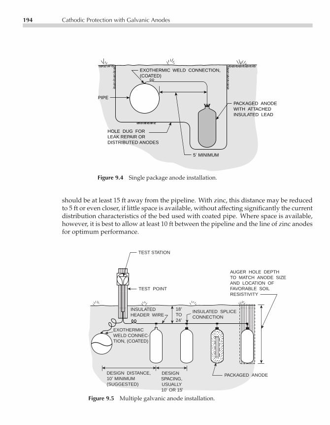
P1: GKW/SPH P2: GKW/UKS P3: GKW/UKS QC:CE003-09 CE003-Peabody November 9, 2000 14:18 Char Count= 0
194 Cathodic Protection with Galvanic Anodes
PACKAGED ANODEWITH ATTACHEDINSULATED LEAD
5 MINIMUM
HOLE DUG FORLEAK REPAIR ORDISTRIBUTED ANODES
PIPE
EXOTHERMIC WELD CONNECTION,(COATED)
Figure 9.4 Single package anode installation.
should be at least 15 ft away from the pipeline. With zinc, this distance may be reducedto 5 ft or even closer, if little space is available, without affecting significantly the currentdistribution characteristics of the bed used with coated pipe. Where space is available,however, it is best to allow at least 10 ft between the pipeline and the line of zinc anodesfor optimum performance.
TEST STATION
AUGER HOLE DEPTHTO MATCH ANODE SIZEAND LOCATION OFFAVORABLE SOILRESISTIVITY
TEST POINT
INSULATEDHEADER WIRE
PACKAGED ANODEDESIGN SPACING,USUALLY10 OR 15
DESIGN DISTANCE,10 MINIMUM (SUGGESTED)
EXOTHERMICWELD CONNEC-TION, (COATED)
18TO24
INSULATED SPLICE CONNECTION
Figure 9.5 Multiple galvanic anode installation.
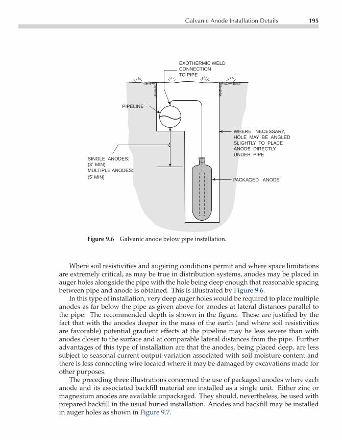
P1: GKW/SPH P2: GKW/UKS P3: GKW/UKS QC:CE003-09 CE003-Peabody November 9, 2000 14:18 Char Count= 0
Galvanic Anode Installation Details 195
EXOTHERMIC WELDCONNECTIONTO PIPE
PACKAGED ANODE
WHERE NECESSARY,HOLE MAY BE ANGLEDSLIGHTLY TO PLACEANODE DIRECTLYUNDER PIPE
SINGLE ANODES:(3’ MIN)MULTIPLE ANODES: (5' MIN)
PIPELINE
Figure 9.6 Galvanic anode below pipe installation.
Where soil resistivities and augering conditions permit and where space limitationsare extremely critical, as may be true in distribution systems, anodes may be placed inauger holes alongside the pipe with the hole being deep enough that reasonable spacingbetween pipe and anode is obtained. This is illustrated by Figure 9.6.
In this type of installation, very deep auger holes would be required to place multipleanodes as far below the pipe as given above for anodes at lateral distances parallel tothe pipe. The recommended depth is shown in the figure. These are justified by thefact that with the anodes deeper in the mass of the earth (and where soil resistivitiesare favorable) potential gradient effects at the pipeline may be less severe than withanodes closer to the surface and at comparable lateral distances from the pipe. Furtheradvantages of this type of installation are that the anodes, being placed deep, are lesssubject to seasonal current output variation associated with soil moisture content andthere is less connecting wire located where it may be damaged by excavations made forother purposes.
The preceding three illustrations concerned the use of packaged anodes where eachanode and its associated backfill material are installed as a single unit. Either zinc ormagnesium anodes are available unpackaged. They should, nevertheless, be used withprepared backfill in the usual buried installation. Anodes and backfill may be installedin auger holes as shown in Figure 9.7.
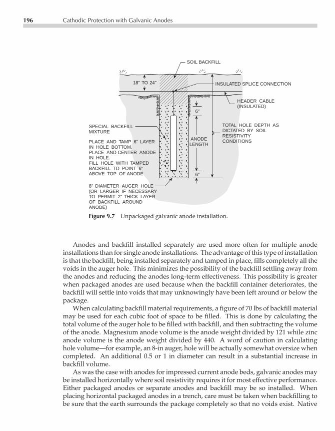
P1: GKW/SPH P2: GKW/UKS P3: GKW/UKS QC:CE003-09 CE003-Peabody November 9, 2000 14:18 Char Count= 0
196 Cathodic Protection with Galvanic Anodes
SOIL BACKFILL
18" TO 24"
SPECIAL BACKFILLMIXTURE
PLACE AND TAMP 6" LAYERIN HOLE BOTTOM.PLACE AND CENTER ANODEIN HOLE.FILL HOLE WITH TAMPEDBACKFILL TO POINT 6"ABOVE TOP OF ANODE
8" DIAMETER AUGER HOLE(OR LARGER IF NECESSARYTO PERMIT 2" THICK LAYEROF BACKFILL AROUNDANODE)
ANODELENGTH
6"
6"
TOTAL HOLE DEPTH ASDICTATED BY SOILRESISTIVITYCONDITIONS
HEADER CABLE(INSULATED)
INSULATED SPLICE CONNECTION
Figure 9.7 Unpackaged galvanic anode installation.
Anodes and backfill installed separately are used more often for multiple anodeinstallations than for single anode installations. The advantage of this type of installationis that the backfill, being installed separately and tamped in place, fills completely all thevoids in the auger hole. This minimizes the possibility of the backfill settling away fromthe anodes and reducing the anodes long-term effectiveness. This possibility is greaterwhen packaged anodes are used because when the backfill container deteriorates, thebackfill will settle into voids that may unknowingly have been left around or below thepackage.
When calculating backfill material requirements, a figure of 70 lbs of backfill materialmay be used for each cubic foot of space to be filled. This is done by calculating thetotal volume of the auger hole to be filled with backfill, and then subtracting the volumeof the anode. Magnesium anode volume is the anode weight divided by 121 while zincanode volume is the anode weight divided by 440. A word of caution in calculatinghole volume—for example, an 8-in auger, hole will be actually somewhat oversize whencompleted. An additional 0.5 or 1 in diameter can result in a substantial increase inbackfill volume.
As was the case with anodes for impressed current anode beds, galvanic anodes maybe installed horizontally where soil resistivity requires it for most effective performance.Either packaged anodes or separate anodes and backfill may be so installed. Whenplacing horizontal packaged anodes in a trench, care must be taken when backfilling tobe sure that the earth surrounds the package completely so that no voids exist. Native

P1: GKW/SPH P2: GKW/UKS P3: GKW/UKS QC:CE003-09 CE003-Peabody November 9, 2000 14:18 Char Count= 0
Galvanic Anode Installation Details 197
Detail of connection to strip anode
Detail of strip anode splice
1000 MAX
FENCE LINE OR OTHERCONVENIENT TESTPOINT LOCATION
POST-MOUNTED TEST STATIONCROSS CONNECTION MAY BEUNDERGROUND IF SUITABLELOCATION FOR TEST POINTDOES NOT EXIST
CONNECTIONTO PIPE
SPLICESEE DETAIL
STRIP ANODE OF MAGNESIUMOR ZINC SURROUNDEDWITH SPECIAL BACKFILL
SEE DETAIL OFCONNECTION TOSTRIP ANODEEXOTHERMIC WELD OR
CRIMP-TYPECONNECTION
INSULATED WIRETO TEST POINT
EXPOSE APPROXIMATELY3" OF CORE WIRE BYMELTING AWAY ZINCWITH TORCH.
2 HALF-LAPPEDLAYERS OF RUBBERTAPE AND 2 HALF-LAPPED LAYERS OFPVC SELF-ADHESIVETAPE
EXPOSE 2" OF CORE WIREON EACH END AND JOINWITH EXOTHERMIC WELD ORCRIMPED CONNECTION
Note: Magnesium anode should never be melted with torch. Expose steel wire core by carefully cutting magnesium with knife or sharp object.
Figure 9.8 Continuous galvanic anode installation.
earth then may be used to complete the trench backfill (after making all anode leadconnections and insulating them).
In some applications, long strip (ribbon) anodes of either magnesium or zinc maybe plowed in parallel to the pipeline along sections of bare or poorly coated line wherecontinuous local protection is required. General features of a strip anode installation areshown by Figure 9.8.
The steel wire core of strip anodes provides continuous longitudinal electrical con-ductivity even after the anode material is consumed completely in some areas (it will beused up first, in the lower soil resistivity sections). Connections between the pipelineand anode core wire should be made at intervals to complete the protection circuit. If

P1: GKW/SPH P2: GKW/UKS P3: GKW/UKS QC:CE003-09 CE003-Peabody November 9, 2000 14:18 Char Count= 0
198 Cathodic Protection with Galvanic Anodes
these cross connections can be made at test points located at fence lines or other con-venient location, it will be possible to measure current flow periodically and estimatethe rate of anode material consumption. Intervals between cross connections shouldnot be too great because there will be some voltage drop in the strip anode, with thisvoltage drop increasing with time as the strip cross-sectional area is reduced as activematerial is consumed. Although this effect will vary depending on the soil resistivityand total current being carried by the strip anode, it is suggested that the interval notexceed 1000 ft.
Spacing between the strip anode and pipeline is not critical. To remain clear of thepipe during plowing-in operations, a spacing of at least 5 ft from the near edge of thepipe may be used. The anode strip should be deep enough to be used in continuouslymoist soil. No less than 2 ft is suggested and greater depths will be necessary in areaswhere soils are subject to deep drying out during dry periods.
Strip anodes of magnesium or zinc are furnished bare. Using such anodes in earthwithout a special backfill involves risk of anode passivation and inadequate amountsof current. For most reliable results, the strip anode should be plowed in with suitablespecial backfill. An adequate allowance, assuming satisfactory dispersion around theanode, is 70 lbs of backfill per 100 ft of strip.
Strip anodes may be used favorably in areas where soil conditions permit the useof tractor-drawn plows fitted to carry trail reels of anode strip and a backfill supply.Rocky or very rough terrain may preclude the use of this type of anode as openinga continuous ditch in the conventional manner would, in most instances, be toocostly.
Test points for multiple anode locations may be installed as shown in Figure 9.9.The shunt in the test point terminal box makes it possible to measure the current
from the anodes (using a millivoltmeter as shown) without disturbing the circuit. Thecommon 0.01 ohm shunt does not have enough resistance to have a substantial effecton the anode current output in most cases. If a solid link is used instead of the shunt,however, good practice is to use an ammeter circuit for measuring the anode current ora clamp-on ammeter as discussed in Chapter 6. The separate test wire from the pipeline,as shown in the figure, makes it possible to measure accurately the pipeline potential to acopper sulfate reference electrode. Pipe and anode leads for multiple anode installationsmay, typically, be No. 8 AWG copper wire with insulation suitable for direct burial insu-lation. The separate potential test wire should not be smaller than No. 12 AWG insulatedwire.
With galvanic anode installations, all wire connected to the anode tends to beprotected. This means that if any copper is exposed, it will not tend to corrode andcause severing of the wire as will happen if there is any break in the insulation in wiresconnected to the positive terminal of the DC power source in an impressed current CPsystem. Because of this, insulation of underground connections on galvanic anode instal-lation is not as critical but should nevertheless be well done to prevent current loss. Also,if anything other than brazed, soldered or welded connections are used (such as crimpor compression connections), the connection should be waterproofed completely to pre-vent possible development of resistance within the joint. Probably the most important

P1: GKW/SPH P2: GKW/UKS P3: GKW/UKS QC:CE003-09 CE003-Peabody November 9, 2000 14:18 Char Count= 0
Galvanic Anode Installation Details 199
−+ V
+−MV
0.01 OHM WIRESHUNT.0.1 AMP PER MILLIVOLT DROP
INSULATED WIRETO ANODES
INSULATED CURRENT-CARRYING AND TESTWIRES TO PIPELINE
CONDUITBUSHING
CONDUITSTRAP
PVC ORGALVANIZEDSTEEL CONDUIT3/4" OR 1
TEST STATION
TEST POINT SUPPORT4" × 4" × 6 TREATED WOOD POSTOR 2" TO 4" × 6 STEEL PIPE
Figure 9.9 Galvanic anode test station installation.
connection in a galvanic anode system from an insulation standpoint is the connectionbetween the pipeline and the copper anode lead. The strong dissimilar metal corrosioncell between steel and copper needs to be thoroughly and permanently waterproofed toprevent any possibility of pipe corrosion immediately adjacent to the connection wherethe corrosion cell may not be overcome completely by the applied CP. This can occurparticularly when bare copper wire lies closely parallel to bare steel such that the wireacts as an electrical shield and prevents protective current from reaching the steel.
When galvanic anode installations are first set up, they may not attain maximumcurrent output for some time. This is because the dry backfill mixture may take upmoisture slowly from the surrounding soil. Unless the surrounding soil is very wet, itmay be several days or even weeks before maximum output is attained. If dry soilconditions prevail, wetting the soil above the anode after installation will help. Theobvious solution of mixing the backfill with water before installation is not necessarilya good one because shrinkage may result, with possible development of voids whenexcess water leaves the backfill. On the other hand, well-tamped dry backfill tends toexpand upon taking up moisture from the surrounding soil, thus ensuring intimatecontact throughout the backfill column.
P1: UBICE003-10 CE003-Peabody November 6, 2000 10:2 Char Count= 14643
Chapter10Cathodic Protection withOther Power Sources
John A. Beavers
Although most impressed current cathodic protection (CP) systems use AC power sup-plied by utilities in conjunction with rectifiers as a source of DC current, there are severalother power sources that may be used if AC power lines are not available. Some of thesehave been in use for some time; others are relatively new; and still others are in thedevelopment stage. Many of these alternative power sources are expensive; therefore,the corrosion engineer must make certain that the same degree of protection cannot beobtained at less cost by other means such as by galvanic anodes.
ENGINE-GENERATORS
Engine-generator sets may be used to provide the electrical energy for CP rectifiers if alarge power source is needed and AC power lines are not available. Gas from the pipelinemay be used to power the engine for a CP system on a natural gas pipeline. If the linecarries a petroleum product suitable for engine fuel, this may be taken directly from theline as well. Otherwise, fuel must be brought to the generator station periodically.
Present practice is to use an engine coupled with an AC generator (alternator). Thepower from the alternator is fed to a conventional rectifier that supplies the direct currentenergy required for the CP installation, as shown in Figure 10.1. The DC power outputfrom the rectifier is used in the conventional manner to supply current to ground beds(surface or deep well) as discussed in Chapter 7.
The reasons for using an alternator and conventional rectifier rather than generatingdirect current are the following:
1. The alternator requires less maintenance on its slip rings than a DC generator requireswith its commutator, and
201
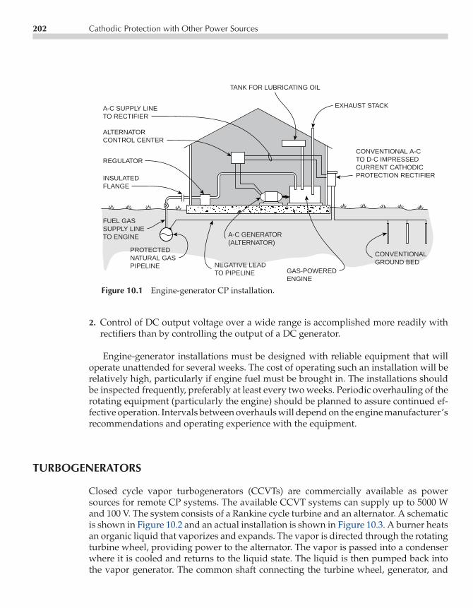
P1: UBICE003-10 CE003-Peabody November 6, 2000 10:2 Char Count= 14643
202 Cathodic Protection with Other Power Sources
TANK FOR LUBRICATING OIL
A-C SUPPLY LINETO RECTIFIER
ALTERNATORCONTROL CENTER
REGULATOR
INSULATEDFLANGE
EXHAUST STACK
CONVENTIONAL A-C TO D-C IMPRESSEDCURRENT CATHODIC PROTECTION RECTIFIER
CONVENTIONALGROUND BED
GAS-POWEREDENGINE
A-C GENERATOR(ALTERNATOR)
NEGATIVE LEADTO PIPELINE
PROTECTEDNATURAL GASPIPELINE
FUEL GASSUPPLY LINETO ENGINE
Figure 10.1 Engine-generator CP installation.
2. Control of DC output voltage over a wide range is accomplished more readily withrectifiers than by controlling the output of a DC generator.
Engine-generator installations must be designed with reliable equipment that willoperate unattended for several weeks. The cost of operating such an installation will berelatively high, particularly if engine fuel must be brought in. The installations shouldbe inspected frequently, preferably at least every two weeks. Periodic overhauling of therotating equipment (particularly the engine) should be planned to assure continued ef-fective operation. Intervals between overhauls will depend on the engine manufacturer’srecommendations and operating experience with the equipment.
TURBOGENERATORS
Closed cycle vapor turbogenerators (CCVTs) are commercially available as powersources for remote CP systems. The available CCVT systems can supply up to 5000 Wand 100 V. The system consists of a Rankine cycle turbine and an alternator. A schematicis shown in Figure 10.2 and an actual installation is shown in Figure 10.3. A burner heatsan organic liquid that vaporizes and expands. The vapor is directed through the rotatingturbine wheel, providing power to the alternator. The vapor is passed into a condenserwhere it is cooled and returns to the liquid state. The liquid is then pumped back intothe vapor generator. The common shaft connecting the turbine wheel, generator, and

P1: UBICE003-10 CE003-Peabody November 6, 2000 10:2 Char Count= 14643
Turbogenerators 203
Figure 10.2 Schematic of a closed cycle vapor turbogenerator. (Courtesy ofOrmat.)

P1: UBICE003-10 CE003-Peabody November 6, 2000 10:2 Char Count= 14643
204 Cathodic Protection with Other Power Sources
Figure 10.3 Installation of a closed cycle vapor turbogenerator on a gaspipeline in the western United States. (Courtesy of Ormat.)
pump is the only moving part in the system. This shaft is supported by working fluidfilm bearings, minimizing wear and associated maintenance.
CCVT systems can operate on a variety of fuels, including natural gas, liquifiedpetroleum gas, kerosene, jet fuel, and diesel fuel. With natural gas, the burner should beinspected and cleaned, if necessary, annually. More frequent cleaning may be requiredif less clean fuels are used.
THERMOELECTRIC GENERATORS
It has long been known that heating a junction of certain dissimilar metals could generateelectricity. These junctions (thermocouples) are used widely as a means of measuringtemperature—the voltage output of the heated junction being fed to a voltmeter cali-brated in degrees. In the earliest attempts to use this principle as a CP power source,large numbers of low-capacity metallic junctions were connected in series-parallel com-binations and heated with a gas flame to attain the necessary DC output capacity. Thesedesigns were not particularly successful because of failure of the junctions used.
In recent years, there has been rapid development of higher capacity semiconductingthermoelectric materials designed specifically for power-generation use. Figure 10.4 is a

P1: UBICE003-10 CE003-Peabody November 6, 2000 10:2 Char Count= 14643
Thermoelectric Generators 205
ELECTRICAL INSULATOR
THERMAL INSULATIONINSIDE HERMETICALLYSEALED POWER UNIT
HEAT PIPE FLUID
COOLING FINS
HEAT PIPES
COLD ELECTRODESELEMENTS
HOT ELECTRODES
BURNER
−P+
−P+
−P+
+N−
+N−
+N−
Figure 10.4 Schematic of a thermoelectric generator. (Courtesy ofGlobal Thermoelectric, Inc.)
schematic showing the operation of a thermoelectric generator and Figure 10.5 shows anactual installation. A thermocouple is formed by a P type and an N type thermoelectricleg joined together electrically by a hot junction electrode. Adjacent thermocouples arejoined together by cold junction electrodes with each pair producing about 90 mV. Sev-eral hundred thermocouple pairs are connected in series to provide the desired outputvoltage. The hot junction is maintained at a high temperature (about 1000F) using nat-ural gas or propane while the cold junction is cooled with heat pipes to maintain a lowertemperature (about 325F). The heat pipe is hermetically sealed and contains a specialfluid in equilibrium with its vapor. As heat is applied to the fluid, it boils, carrying heatwith it. The vapor rises to the finned portion of the pipe and condenses because of thecooling effect of the fins.
Standard thermoelectric generator units are available at power outputs up to 600 Wand voltages up to 48 V. Higher power outputs can be achieved by adding parallel units.If higher voltages are required for a CP installation, it is also possible to convert thelow DC voltage from the generator to a higher DC voltage. The converters, althoughof high efficiency, do cause some power loss. For this reason, maximum efficiency will

P1: UBICE003-10 CE003-Peabody November 6, 2000 10:2 Char Count= 14643
206 Cathodic Protection with Other Power Sources
Figure 10.5 Installation of a thermoelectric generator. (Courtesy of Global Thermo-electric, Inc.)
result if ground beds can be built to directly use the output of the thermoelectric gen-erator. Designing ground beds without carbonaceous backfill will reduce the appliedvoltage requirement by reducing the groundbed back voltage substantially. When plan-ning an installation where a thermoelectric generator may be applicable, check with theequipment manufacturers for the latest equipment specifications. Since thermoelectricgenerators contain no moving parts, maintenance is minimal. Annually, it is necessaryto replace the fuel filter and clean the fuel orifice.
SOLAR ELECTRIC POWER SYSTEMS
In areas where sunlight can be expected for relatively large percentages of the time, acombination of solar cells and storage batteries can be used to provide a continuous flowof current to a CP installation. A typical installation is shown in Figure 10.6. Solar cellsrely on the photoelectric effect: a process in which a material liberates an electric chargewhen electromagnetic radiation (sunlight) is incident on the material surface. Solar cellsare typically P-N junction semiconductors fabricated of crystalline silicon and doped toprovide the desired photovoltaic properties.

P1: UBICE003-10 CE003-Peabody November 6, 2000 10:2 Char Count= 14643
Batteries 207
Figure 10.6 Typical solar electric CP installation.(Courtesy of Kyocera Solar, Inc.)
The initial cost of the solar electric powered CP systems has dropped dramaticallyover the past 20 years as the technology has advanced. This advancement has occurred,in part, as a result of rapid development in the semiconductor industry in general. Solarelectric power systems also are used for other applications such as satellite communica-tions and cellular telephony. Systems are now available that operate at power outputsup to 1000 W, voltages up to 20 V, and currents up to 50 A. Battery storage capacities upto 3200 A-h (at 12 V) are available. Such a battery backup could supply a 10 A rectifierfor almost two weeks with no recharging.
BATTERIES
The cost of electrical energy from batteries is high. Occasionally, however, they have beenused to supply CP current to isolated sections of well-coated pipe where power lines arenot available and where galvanic anodes will not supply the necessary protective currentat less cost. Figure 10.7 illustrates the use of batteries on a well-coated river crossing.
Note that the ground bed shown in the figure is scrap steel. High silicon cast ironanodes without carbonaceous backfill may be used also. Graphite anodes or other anodesbackfilled with carbonaceous material are not favored because of the characteristic backvoltage (usually around 2 V) which would have to be overcome with extra batterycapacity.

P1: UBICE003-10 CE003-Peabody November 6, 2000 10:2 Char Count= 14643
208 Cathodic Protection with Other Power Sources
+ −
RIVER
BATTERY INWEATHERPROOFPOLE-MOUNTEDHOUSING.
SCRAP STEELGROUND BED
INSULATEDFLANGES
PIPELINE
INSULATEDFLANGES
Figure 10.7 Battery-powered CP installation.
WIND-POWERED GENERATORS
Wind-powered generators may be used as a source of power in areas where prevailingwinds are of sufficient intensity and duration. Such units were used fairly extensivelyin the early days of pipeline CP. However, they are expensive and require quite a lot ofmaintenance. Their use for this application has declined with the development of morecost-effective, reliable power sources, such as solar cells, CCVTs, and thermoelectricgenerators. Nevertheless, wind-powered generators may be considered as one methodof providing power for CP systems in remote areas. Because the power output from awind-powered generator will be neither steady nor continuous, some means must beused to assure a steady supply of current to the CP ground bed. This can be done byusing storage batteries.
When designing a wind-powered installation, wind conditions must be evaluatedthoroughly so that both the generator and storage battery can be sized properly. Thestorage batteries used must have sufficient capacity to supply the required CP currentthroughout the duration of the longest probable windless period. Likewise, the generatormust have sufficient capacity to both supply the CP current and recharge the batteriesduring periods of sufficient wind.
Wind-powered generator installations require significant maintenance. Lubricationof the generator bearings and mounting swivel (unless they are the lubricated-for-lifetype) must be scheduled on a regular basis. Generator commutator and brushes as well as

P1: UBICE003-10 CE003-Peabody November 6, 2000 10:2 Char Count= 14643
Gas Turbines 209
slip rings and brushes at the mounting swivel must be checked periodically, cleaned, anddressed when worn. Storage batteries require close attention to maintain the electrolyteat the proper level.
GAS TURBINES
Gas turbines can be used to drive DC generators on natural gas pipelines if there is anadequate pressure drop available. The installation of such a device across a deliverystation is illustrated in Figure 10.8. The gas is diverted to the turbine through a bypassline and returned to the system without loss. Similar systems can be established at otherlocations on gas systems where reasonably constant pressure drops are available, such asin producing gas fields, at well heads, and on gas transmission pipelines. The principaldisadvantage of gas turbine power sources is the restricted number of locations wherethey can be used. For this reason, they are not widely installed.
TRANSMISSIONPIPELINE
INSULATEDFLANGES
PRESSUREREDUCTIONEQUIPMENTAT DELIVERYSTATION
DISTRIBUTIONSYSTEM MAIN
GAS TURBINE
D-C GENERATOR
CATHODICPROTECTIONGROUNDBED
REGULATOR(WHERE NECESSARY)
V
A
− +
Figure 10.8 Gas turbine CP installation.
P1: UBICE003-10 CE003-Peabody November 6, 2000 10:2 Char Count= 14643
210 Cathodic Protection with Other Power Sources
FUEL CELLS
The fuel cell is still another source of DC energy that is subject to intensive developmentas a result of space exploration and military applications and, most recently, automotiveapplications. In its simplest form, the basic fuel cell can be visualized as a sandwich oftwo porous electrically conducting plates (or electrodes) with an electrolyte filling thespace between the plates. A gaseous fuel such as hydrogen is forced through one plateinto the cell, and an oxidizing agent such as oxygen gas is forced through the other plate.
Within the porous electrodes, the fuel and oxidant react electrochemically with theelectrolyte to produce electricity and water. Leads from the two porous electrodes serveto remove the electricity generated. Cell developments are in the areas of porous elec-trode formulation, electrolytes, and catalysts that will permit long-term cell performanceat optimum output. Development is active also in the technology of fuel cells that usefuels other than hydrogen and oxygen. The pipeline corrosion engineer will have an-other useful DC power source for impressed current CP installations when fuel cells aredeveloped commercially at practical cost that can use natural gas or propane as fuels.

P1: UBICE003-11 CE003-Peabody November 3, 2000 11:58 Char Count= 0
Chapter11Stray Current Corrosion
Michael J. Szeliga
The major emphasis of the preceding chapters has been on corrosion and the use ofcorrosion control methods to combat it successfully. The stray currents associated withpipeline corrosion problems are, as the designation implies, direct currents flowing inthe earth from a source other than that associated with the affected pipeline. To causecorrosion on a pipeline, stray direct current (DC) must flow from an outside sourceonto the pipeline in one area and then flow along the line to some other area or areaswhere they leave the pipe to reenter the earth (with resulting corrosion) and completethe circuit by returning to the original DC power source. Stray currents are either static(nonvarying) or dynamic (varying). Stray current sources include the following: im-pressed current cathodic protection (CP) systems on other pipelines, DC transit systems,DC mining operations, DC welding operations, high voltage DC transmission systemsand disturbances of the earth’s magnetic field. On occasion, AC current flow to groundon electrical distribution systems may be rectified if environmental conditions are suchthat rectifying junctions can be formed such as certain copper oxide films on copper orcopper jacketed ground rods. The resulting direct current could create a stray currentproblem (usually minor) that can be mitigated by the procedures described below forthe more usual sources of stray DC currents.
The purpose of this chapter is to outline the fundamentals involved in recognizing,testing for and correcting stray current corrosion conditions. The ability to deal with suchsituations is important to the pipeline corrosion engineer. This is because the magnitudeof stray current discharge from a pipeline at a given point may be far greater than thatof galvanic corrosion currents experienced elsewhere on the line. Failure to correct straycurrent discharge, can lead to early pipeline leaks.
STRAY CURRENT FROM CATHODIC PROTECTION INSTALLATIONS
Impressed current CP systems can cause stray current interference on adjacent pipelinesdepending on the location of the ground beds, the exact location of the pipeline and the
211

P1: UBICE003-11 CE003-Peabody November 3, 2000 11:58 Char Count= 0
212 Stray Current Corrosion
PROTECTEDPIPELINE
RECTIFIER
FOREIGNPIPELINEOR OTHERMETALLICSTRUCTURE
CURRENT FLOWFROM FOREIGNSTRUCTURE TOPROTECTED LINEIN CROSSINGAREA
ENDWISECURRENT
AREA OF INFLUENCE SURROUNDINGGROUND BED. WITHIN THIS AREASOIL POTENTIALS ARE POSITIVE(+) WITH RESPECT TO REMOTEEARTH.
+−
REMOTEGROUND BED
Figure 11.1 Foreign pipeline damage by cathodicprotection installation—case 1.
operating characteristics of the CP system. Figures 11.1 to 11.4 illustrate the conditionsthat can result in this type of stray current interference.
Testing for Interference
Testing for static stray DC current interference caused by CP systems is reasonablystraightforward in areas where there are no complications caused by the presence of
GROUNDBED
AREA OF INFLUENCESURROUNDING THEGROUND BED.
ENDWISECURRENT FLOW.
FOREIGN PIPELINENOT CROSSINGPROTECTED LINE.
CURRENTDISCHARGEFROM FOREIGNPIPELINE INREMOTE AREAS.
PROTECTED PIPELINE
+−
RECTIFIER
Figure 11.2 Foreign pipeline damage by cathodic protectioninstallation—case 2.

P1: UBICE003-11 CE003-Peabody November 3, 2000 11:58 Char Count= 0
Stray Current from Cathodic Protection Installations 213
PRO-TECTED
LINE
+− + − +−
Figure 11.3 Potential gradients in earth aroundcathodically protected pipeline.
superimposed dynamic (variable) stray currents from sources such as DC powered tran-sit systems. Figure 11.5 illustrates an example where an impressed current CP system(incorporating a rectifier as a DC power source) has been applied to a section of coatedpipeline that has several foreign pipelines crossing it. Assume that at each foreign linecrossing, a test station has been installed, as shown in the detail on the figure, with two
AREA OFINFLUENCESURROUNDINGPROTECTEDPIPELINE.
FOREIGNPIPELINE
MOST INTENSE CURRENTDISCHARGE AND GREATESTCORROSION DAMAGE TOFOREIGN LINE IS NORMALLYAT POINT OF CROSSING.
FOREIGN LINE TENDSTO BECOME POSITIVETO SOIL WITHIN AREAOF INFLUENCE AND ISFORCED TO DISCHARGECURRENT.
CURRENTPICKED UPBY FOREIGNPIPELINEOUTSIDE AREAOF INFLUENCE
PROTECTEDPIPELINE.
Figure 11.4 Effect on foreign pipeline passing through earthpotential gradients around cathodically protected bare line.

P1: UBICE003-11 CE003-Peabody November 3, 2000 11:58 Char Count= 0
214 Stray Current Corrosion
FOREIGNLINE A
FOREIGNLINE B
FOREIGNLINE C
FOREIGNLINE D
PICKUP
STATION900 + 00
STATION915 + 00
STATION10 + 00
DISCHARGECURRENTINTERRUPTERINSERTED FORTESTS.
PROTECTED LINEUNDER TEST
RECTIFIERGROUND BEDINSTALLATION
PIPELINE E
RECTIFIER AND GROUNDBED ON FOREIGN LINE
+ − V
2 BLACK LEADS
FOREIGN LINE
PROTECTEDLINE
2 WHITE LEADS
STATION1765 + 00
STATION1815 + 00
(OWN PIPELINE)
Figure 11.5 Testing foreign pipeline crossings for stray current interference from CPinstallations.
color-coded leads brought to the test station terminal board from each pipe. An automaticcurrent interrupter (a device for automatically opening and closing an electrical circuitat preset time periods) may then be installed in the output of the rectifier as shown.The interrupter may be set to operate at a cycle such as 20 seconds, current ON, and10 seconds current OFF, so that the effect of the CP current on the foreign pipelines can beclearly distinguished. With the current interrupter operating, each foreign line crossingis visited and the potential of each line is measured under both current ON and currentOFF conditions. For these tests, the copper sulfate electrode (CSE) is placed directly overthe point of crossing. If there is any question as to the crossing location, a pipe locator

P1: UBICE003-11 CE003-Peabody November 3, 2000 11:58 Char Count= 0
Stray Current from Cathodic Protection Installations 215
Table 11.1 Survey Notes on Stray Current Investigation
Potential Vs Close (CSE)Foreign LineDesignation & Location (E) Own Pipeline, V Foreign Pipeline, V
With Current With CurrentPipelineName Station ON OFF 1V ON OFF 1V
A 10+ 00 −0.88 −0.85 −0.03 −0.87 −0.89 +0.02B 900+ 00 −1.98 −1.02 −0.96 −0.32 −0.68 +0.36C 1765+ 00 −0.68 −0.64 −0.04 −0.78 −0.78 0D 1815+ 00 −0.95 −0.91 −0.04 −0.68 −0.68 0
should be used to determine exactly where it is. See Chapters 5 and 6 on instrumentationand techniques for information on equipment and test procedures.
Data taken at the several pipeline crossings of Figure 11.5 may be recorded as shown inTable 11.1. The data shown in the table illustrate various types of stray current interferenceeffects that may be encountered. In addition to the data shown for this illustration, fielddata sheets should include full information on the line protected, date, current output ofthe interrupted rectifier and other pertinent facts. Following are some conclusions thatcan be reached from the data as well as notes on supplementary tests that can be madewhere appropriate.
Crossing A
Pipeline E (own pipeline) is fully protected, but may have a substantial coating holidayin the vicinity of the crossing because the potential of the foreign line decreases when theinterrupted rectifier switches from OFF to ON. This indicates that there is appreciablecurrent flowing to the line under test, creating more negative soil locally around theforeign line.
The foreign line in this instance appears to be cathodically protected as indicatedbecause its potential at the crossing, with the line E rectifier turned OFF, is −0.89 V. Thepotential of pipeline A becomes less negative (−0.87 V) when the line E rectifier is ON.This indicates that the line E rectifier is reducing the protective potential on pipeline A.However, the reduction is probably not sufficient to suggest a loss of protection. To verifyfull protection on line A, additional testing should be performed with the CP system forthe foreign line interrupted while the rectifier for pipeline E is turned ON. The dataindicate that no corrective measures would probably be required for pipeline A.
Crossing B
Pipeline E is fully protected. Pipeline B is not cathodically protected (at least not fully)because its potential is well below −0.85 V to CSE with the line E rectifier OFF. With

P1: UBICE003-11 CE003-Peabody November 3, 2000 11:58 Char Count= 0
216 Stray Current Corrosion
the line E rectifier ON, the potential on line B is shifted severely in the less negativedirection, indicating the probability of severe stray current corrosion damage to theforeign line. Corrective measures will be required to protect line B from stray currentcorrosion damage.
From the location of line B, crossing only 1,500 ft from the line E rectifier and itsroute carrying into the vicinity of the line E ground bed, the interference can be expectedto result from current pickup by line B where it passes through the area of influencesurrounding the line E ground bed. Two verification tests can be made. First, if thepotential of Line E is the same, or nearly so, with reference to a remote electrode as itis to the electrode directly over the point of crossing, coating damage on line E is notprobable as was the case at the crossing with line A. Second, if the potential of line B toan electrode placed directly over it in areas where it approaches the ground bed swingsin the negative direction when the rectifier is switched ON, current pickup by line B isindicated.
Finally, where interference is found (as in this case) it is necessary to determine ifthe actual point of crossing is the point of maximum exposure. This is done by mov-ing the electrode a few feet at a time, five ft to start, first in one direction and then inthe other away from the point of crossing and directly over line B to see if there is anarea in which the positive delta voltage swing is greater than at the point of crossing.If such an area is found, the electrode may be moved by smaller distance incrementswithin this area until the point of maximum exposure is found. Identify the locationand record the ON, OFF and delta voltages at this point. Rarely will it be necessaryto go more than 100 ft in either direction from the point of crossing. The maximumexposure point may be other than at the point of crossing if soil resistivity varies ap-preciably in the crossing area or if the coating (if any) on the foreign line varies inquality.
Crossing C
Line E, at the crossing with line C, is receiving inadequate protection, apparently becauseof interference from the CP system for Line C. If the potential of line E is measured to aCSE that is remote from both pipelines, and this potential is found to be representativeof normal protective potentials (above −0.90 V in this case), the low potential at thecrossing is a localized condition that is probably caused by the CP system on line C.Corrective measures will be required. The length of the line under test that is below−0.85 V can be determined by taking readings to an electrode placed directly above lineE in each direction from the point of the crossing with line C. If the data, when plotted,give a curve similar to that in Figure 11.6, interference from the protection system online C is confirmed. Pipeline C, in this case, is not affected adversely by the CP systemfor line E. There was no change in the line C potential with the line E rectifier ONand OFF.
P1: UBICE003-11 CE003-Peabody November 3, 2000 11:58 Char Count= 0
Stray Current from Cathodic Protection Installations 217
−+V
+−MV+−MV
CURRENTPICKUPAREA
CURRENTDISCHARGEAREA
PROTECTEDPIPELINE
CURRENTINTERRUPTER
RECTIFIER ANDGROUND BED
LINE CURRENTMEASUREMENT
(EAST SIDE)
LINE CURRENTMEASUREMENT
(WEST SIDE)
TESTPOINT
TESTPOINT
FOREIGN LINESUBJECT TOINTERFERENCE
SET UP FOR OVER-THE-LINEPOTENTIAL SURVEY
PLOT OF OVER-THE-LINE POTENTIAL SURVEY ON PARALLEL FOREIGN LINE
∆V I
N V
OLT
S(+
)
(−)
DISTANCE IN FEET
Figure 11.6 Testing noncrossing foreign pipelines for stray current interferencefrom installations.
Crossing D
Pipeline E is protected adequately. Pipeline D does not have full protection but is notaffected by the CP system on the line under test. No corrective action is required.
Another possible situation involving interference can exist with a foreign pipeline thatpasses through the area of influence of a rectifier ground bed, but never actually crossesthe protected pipeline. Testing for interference on such a line is illustrated by Figure 11.6.As shown in the figure, the foreign line can be tested by making an over-the-line potentialprofile in the ground bed area. This can be supplemented, if the profile indicates a current

P1: UBICE003-11 CE003-Peabody November 3, 2000 11:58 Char Count= 0
218 Stray Current Corrosion
Table 11.2 Survey Notes on Investigation of Interference from Ground Bed
Over-the-Line Potentials—Voltson Foreign PipelineElectrode
Locationwith Respect to Rectifier RectifierStarting Point-Ft ON OFF 1CSE(1) Remarks
0 −0.48 −0.52 +0.04 Exposure100 −0.58 −0.58 0200 −0.64 −0.63 −0.01300 −0.69 −0.64 −0.05400 −1.01 −0.69 −0.32500 −1.20 −0.77 −0.43
600 −1.37 −0.81 −0.56 Opposite700 −1.18 −0.78 −0.40 Ground Bed800 −0.99 −0.71 −0.28900 −0.66 −0.65 −0.011000 −0.64 −0.64 0
1100 −0.57 −0.59 +0.02 Exposure1200 −0.48 −0.53 +0.05 Exposure
(1) Values to be plotted
Potential Drop Potential Drop Change in CalculatedRectifier ON Rectifier OFF Potential Drop Interference CurrentForeign Pipeline
Line CurrentMeasurement mV(1) Flow mV(1) Flow 1mV Flow Amp/mV Amps Flow
West Side 0.62 West 0.08 East 0.70 West 3.8(2) 2.66 WestEast Side 0.53 East 0.02 East 0.51 East 4.1 2.09 East
(1) mV readings corrected for lead resistance.(2) Amp/mV factors for the specific voltage drop span.
pickup area, by pipeline current measurements to determine the magnitude of currentpickup. With an interrupter operating at the rectifier on the protected line, the data mightappear as shown in Table 11.2.
The first set of data in Table 11.2, with highly negative values of delta voltage oppo-site the ground bed, indicate definite current pickup. The positive delta voltage valuesindicate the beginning of a current discharge area. The portion of the foreign pipelinethat is picking up current starts at the 100 ft point and continues to the 1,000 ft locationfor a total distance of 900 ft.
The foreign pipeline current flow measurements (second set of data in Table 11.2) in-dicate definite stray current flow along the pipeline with the rectifier ON. The magnitudeof the current flow indicated is high for this type of interference condition. Serious dam-age to the foreign line could be expected at an early date if the condition were allowedto exist without correction.
P1: UBICE003-11 CE003-Peabody November 3, 2000 11:58 Char Count= 0
How to Reduce Stray Current Interference 219
HOW TO REDUCE STRAY CURRENT INTERFERENCE
Some of the methods used to reduce or eliminate stray current interference from CP in-stallations include bonds between the offending and affected pipelines, use of galvanicanodes at the point of crossing, use of coatings, and use of electrical shields. In someinstances, the corrective measures required may be so complicated or expensive thatrelocating the offending rectifier installation may be the more economical solution. Toillustrate how the various corrective procedures may be used, the examples of inter-ference described above in “Testing for Interference” will be used to demonstrate thespecific corrective procedures.
Drainage Bonds
Table 11.1 shows that foreign pipeline B is subject to stray current damage from theimpressed current CP system on pipeline E, see Figure 11.5. A commonly used methodto correct this condition involves connecting a resistance bond between the two pipelineswith the amount of resistance in the bond adjusted to drain just enough current fromthe affected line to eliminate the damaging condition. Normally, this is done duringcooperative tests with the corrosion engineer representing the foreign pipeline ownerunless the owner has given specific permission to make the bond installation withoutrepresentation on his part. Permission should be in writing.
The accurate determination of when the stray current interference effect has beeneliminated is critical. To determine this, the bond is adjusted with the current interrupteroperating at the rectifier on the pipeline causing the interference (as in Figure 11.5)and with a voltmeter set up to measure the potential of the foreign line to CSE at thepoint of crossing (or at the point of maximum exposure if other than at the actual pointof crossing). The bond resistance is made such that the foreign line potential with theaffecting rectifier ON is the same as was observed and recorded for it with the rectifierOFF prior to the installation of the bond. In other words, the foreign pipeline potentialis restored to its original value. A typical foreign line test point with a bond in place isillustrated by Figure 11.7, together with the instrument connections for measuring thepipe-to-soil potentials on affected pipeline.
Assuming that the point of crossing is also the point of maximum exposure in this in-stance (crossing B, Figure 11.5), the original readings for the foreign line are−0.32 V, ON,and −0.68 V, OFF. With the resistance bond adjusted properly, the foreign line potentialwith the rectifier ON should be −0.68 V.
A method of adjusting bonds frequently used, calls for adjusting the bond resistanceuntil there is no swing (delta voltage) on the foreign pipeline at the point of maximumexposure as the affecting rectifier is switched ON and OFF. This no potential shift pro-cedure has been shown over the years1 to be ultra conservative in that more current isdrained by the bond than is necessary to clear the interference. Although this does noharm to the foreign line, the cathodically protected line may be unnecessarily penalized.

P1: UBICE003-11 CE003-Peabody November 3, 2000 11:58 Char Count= 0
220 Stray Current Corrosion
+ −V
BOND TYPICALLYAN ADJUSTABLESLIDE RESISTERCONNECTEDBETWEEN THEHEAVY LEADTERMINALS FORWIRES FROMFOREIGN ANDPROTECTEDLINES
TYPICAL FOREIGN LINE CROSSINGTEST POINT INSTALLATION.TERMINAL BOX MAY BE BURIED,IF NECESSARY, RATHER THANPOST-MOUNTED
HIGH RESISTANCETEST VOLTMETER
COPPER SULPHATEELECTRODE DIRECTLYOVER FOREIGN LINEAT POINT OF MAXIMUMEXPOSURE
FOREIGN LINEBEING AFFECTEDBY STRAY CURRENTINTERFERENCE
PROTECTED PIPELINE WITH RECTIFIER(INTERRUPTED) CAUSING INTERFERENCEON FOREIGN PIPELINE
NO 8 & NO 12 WHITEINSULATED WIRESFROM PROTECTEDLINE
(TYPICAL)NO 8 & NO 12BLACK INSU-LATED WIRESFROM FOREIGNLINE
Figure 11.7 Bond at foreign pipeline crossing.
Had the foreign pipeline in this example been cathodically protected such that fullprotective potentials were lost with the affecting rectifier ON, full return to the origi-nal potential might not be necessary. Assume that, when the crossing was tested, thereadings were the following: −0.55 V, ON; −0.91 V, OFF; +0.36 V, delta voltage. By ad-justing the bond with the rectifier ON until the foreign line reads −0.85 V at point ofmaximum exposure, corrosion would be prevented with no need to return the foreignpipeline potential to the full −0.91 V. The stray current drainage bond would require

P1: UBICE003-11 CE003-Peabody November 3, 2000 11:58 Char Count= 0
How to Reduce Stray Current Interference 221
bi-monthly inspections by qualified personnel to verify that it was in place and operat-ing properly.
Situation Involving Poorly-Coated Line
Table 11.1 shows that the crossing of pipeline E with foreign line C on Figure 11.5 involvesinterference conditions which may not be solved with a bond. Test data taken on this for-eign line suggest that the foreign line causing interference is bare or very poorly coatedat the crossing. Assume, as suggested in proceeding discussion, that the potential of theline under test is measured to a remote CSE and found to be−0.93 V with its rectifier ON,even though a value far below this is measured to an electrode placed at the crossing asa result of the interference. With the rectifier on the foreign pipeline interrupted, the po-tential of the line under test to the electrode at the point of crossing could have, typically,values as follows: −0.68 V, ON; −0.91 V, OFF; +0.23 V, delta voltage. The ON readingneeds to be corrected to at least−0.85 V to eliminate interference, meaning that if a bondis used, it will have to drain current from the line under test. If, however, the potential ofthe foreign line is measured to the remote reference electrode and found to be, for exam-ple, only−0.83 V with its rectifier ON, it becomes apparent that a bond between the twolines will not drain current from the pipeline, as would be necessary to correct the inter-ference. A bond, under these conditions, would not correct the interference, but wouldimpose needless additional burden on the CP system for the coated pipeline under test.
Knowing that a relatively high current density that is flowing through the soil ontothe bare foreign line results in a localized reduction in the protective potential on the lineunder test, one solution is to reduce the density of current flow to the foreign line in thecrossing area. This may be done with coatings as illustrated by Figure 11.8. By applyinga quality coating to the foreign pipeline causing the interference in the crossing area,current flow through the soil to the foreign line is reduced greatly. This means that thevoltage drops in the earth (cathodic field) around the foreign line become negligible andno longer cause a severe local depression of protective potentials on the line under test.The length of foreign line to be coated can be based on the over-the-line potential profileon the line under test, as shown in Figure 11.9, which identifies the length of line subjectto interference. Coated lengths of foreign line are equated with the interference profilelength as shown in Figure 11.8.
Use of Galvanic Anodes
Another means of correcting the interference involves the use of galvanic anodes attachedto the line under test through the area subject to interference from the foreign line asillustrated by Figure 11.10. Basically, this approach involves using the anodic potentialgradient fields surrounding galvanic anodes to offset the cathodic potential gradientfield surrounding the pipeline. For most applications of this type, a single line of anodesbetween the affected pipeline and the one causing the interference will be sufficient to

P1: UBICE003-11 CE003-Peabody November 3, 2000 11:58 Char Count= 0
222 Stray Current Corrosion
DISTANCE A AND B ARE AREASOF DEPRESSED POTENTIALS ON
PIPELINE UNDER TEST PRIORTO CORRECTIVE MEASURES
A’ AND B’, EQUAL TO DISTANCESA AND B RESPECTIVELY, REPRESENT
THE LENGTH OF FOREIGN LINETO BE COATED.
COATING WITH GOODELECTRICAL ANDMECHANICAL STRENGTHAPPLIED TO THE FOREIGNLINE.
FOREIGN LINECAUSING INTER-FERENCE.
LIMIT OFPOTENTIALDEPRESSIONAREA
PROTECTEDPIPELINEUNDERTEST
A
A’
B’
B
Figure 11.8 Use of coating to correct interference at foreign pipeline crossing.
(−)
(+)
0
UN
PR
OT
EC
TE
DP
RO
TE
CT
ED
−0.85 VOLT
POINT OF CROSSINGWITH PROTECTEDBARE LINE.
FOREIGNLINE
AREA OFPOSSIBLE DAMAGE
PROTECTEDBARE LINE
ETC.V
DISTANCE IN FEET ALONG FOREIGN LINE
FO
RE
IGN
PIP
ELI
NE
PO
TE
NT
IAL
TO
CLO
SE
CO
PP
ER
SU
LPH
AT
E E
LEC
TR
OD
E
Figure 11.9 Pipe-to-earth potentials on foreign pipelinepassing through area of influence around cathodically pro-tected bare line.

P1: UBICE003-11 CE003-Peabody November 3, 2000 11:58 Char Count= 0
How to Reduce Stray Current Interference 223
TEST POINT :ONE PIPE LEAD ANDLEAD FROM ANODE
BED JOINED BY LINK ORCURRENT MEASURINGSHUNT. OTHER LEADS
FOR POTENTIAL TESTS
COATED CATHODICALLYPROTECTED PIPELINEAFFECTED BY STRAYCURRENT INTERFERENCEFROM BARE PROTECTEDLINE
AREA OF DEPRESSEDPOTENTIALS AS ARESULT OF INTERFERENCE
PERMANENT REFERENCEELECTRODE(CSE)
1' 2' ETC. TO 5' MAX.CATHODICALLY PROTECTEDBARE OR VERY POORLYCOATED LINE
HEAVIEST ANODE ATPOINT OF MAXIMUMEXPOSURE
FIVE FOOT LONG MAGNESIUMOR ZINC ANODES, PACKAGEDOR BACKFILLED WITH SPECIALFILL
12"±
Figure 11.10 Use of galvanic anodes to correct interference at foreign pipelinecrossing.
mitigate the harmful effects of the interference. There still will be current discharge butthe discharge will be from the anodes rather than the previously affected pipeline. Wherepotential differences are very great as occurs occasionally with stray current from DCtransit systems or mining substations, several strings of anodes may be required forminga cage around the affected line. In such a case, however, anode life may be short unlesssoil resistivity is high.
As shown in the figure, the heaviest anodes would be used at the point of cross-ing where the exposure is most intense while lighter anodes may be used elsewhere.Magnesium anodes are used successfully because they have higher anodic potentialgradient fields than do zinc anodes. The length of the anode string is determined by thelength of the depressed potential area on the affected pipeline. A test point is desirable topermit measuring anode output periodically and to facilitate potential measurements. Inaddition to the normal surface potential measurements, a permanent reference electrodeplaced as shown in the figure will permit checking the underside of the affected lineat the point of maximum exposure. A prepackaged, permanent, CSE placed below thepipeline makes an excellent installation.
Information in proceeding chapters is applicable when working out the design for in-stallations of this type. Factors to be considered include soil resistivity, voltage differencebetween the lines, length of exposure area, and desired life.

P1: UBICE003-11 CE003-Peabody November 3, 2000 11:58 Char Count= 0
224 Stray Current Corrosion
Use of Electrical Shield
Where a pipeline passes through the area of influence surrounding a ground bed, it ispossible to reduce the amount of stray current the line will pick up by using electricalshields. Situations where this may be a solution include examples such as represented byforeign line B in Figure 11.5 and that illustrated by Figure 11.6. The Figure 11.6 conditionis used to illustrate the application of electrical shields as shown by Figure 11.11.
The reason electrical shields of bare pipe may be useful is that they permit utilizationof the cathodic potential gradient fields surrounding the bare pipe connected to therectifier negative terminal. With the foreign line lying between the two shields as shown,
+ −VM− +VM
FOREIGN LINESUBJECT TOINTERFERENCE
STRAY CURRENTPICKUP AREA
ELECTRICAL SHIELDS-BARE PIPE PARALLELTO AFFECTED LINEIN PICKUP AREA
LINE CURRENTMEASUREMENT
PIPELINE CURRENT FLOWSTILL AWAY FROM PICKUPAREA BUT REDUCED INMAGNITUDE WITH SHIELDSCONNECTED IN CIRCUITCURRENT FLOW CAN BEREVERSED (DESIRABLE)WITH GALVANIC ANODESOR BONDS AS SHOWN. RECTIFIER AND
GROUND BED
PROTECTED PIPELINE
GALVANIC ANODES (EACHSIDE) TO REMOVE RESID-UAL STRAY CURRENT.RESISTANCE BONDS BACKTO RECTIFIER NEGATIVECOULD BE USED ALSO.+
−
GROUND BEDAREA OFINFLUENCE
Figure 11.11 Use of electrical shields to reduce stray current interference.

P1: UBICE003-11 CE003-Peabody November 3, 2000 11:58 Char Count= 0
How to Reduce Stray Current Interference 225
it is completely within the gradient field. This cathodic field is in opposition to thepositive ground bed field. The net result is a reduction in the amount of stray currentpicked up by the foreign line. The effect is quite similar to that which has been describedfor a coated and cathodically protected pipeline crossing a cathodically protected bareline, with local loss of protection on the coated line because of a reduction in currentpickup from the soil caused by the cathodic potential gradient field.
The shields shown in the figure will reduce the stray current pickup on the foreignline, but will seldom eliminate it. Interference current still can be expected to flow awayfrom the pickup area to remote discharge points at which the pipe will be corroded. Thiscurrent flow needs to be reversed. This may be done with galvanic anodes or bonds, assuggested on the figure, if the shields have reduced stray current pickup to a reasonablysmall magnitude.
Using shields as described has many disadvantages. The bare pipe shields connectedto the rectifier negative may consume a large portion of the rectifier current output andthus possibly reduce protection of the line to which the rectifier is connected. The barepipe used as shields may be kept small (3/4-in diameter pipe should be satisfactory inmost cases) to keep the current demands within reason. A shield installation as describedcan be expensive to install and expensive to maintain because, probably, a substantialpercentage of the rectifier operating costs will be due to the shields. Because of theseconsiderations, the pipeline corrosion engineer should consider other alternatives care-fully before using shields to be sure that it would not be less expensive, in the long run,to relocate the rectifier and ground bed.
Notification Procedures
An essential part of the pipeline corrosion engineer’s job involves cooperating withowners of other pipelines or buried metallic structures. This is necessary in order thatall parties may plan and operate their corrosion control systems with the least practicaleffect on structures belonging to others. Corrosion engineers should, when cathodicallyprotecting a pipeline, notify all owners of underground structures crossing their pipelinethat a CP system is planned. This should be done before the CP system installationsare made. These foreign structure owners should be given the location, type, and sizeof protection installations to be installed in the vicinity of their crossing or crossings.They should be told when the system is to be energized and they should be invited toparticipate in cooperative tests at points of crossing. They may be promised copies ofdata taken at their crossings if they do not elect to send a representative for cooperativetests. They should be asked if they have additional crossings not known to the engineerissuing the notifications. For clarification, the written notice may be accompanied by astrip map of the pipeline (or pertinent portions thereof) marked to show the foreign linecrossings of the company being notified and the proposed CP installations in the vicinityof those crossings.
Some geographical areas, typically large urban areas, have organized corrosion coor-dinating committees that have established procedures for disseminating information to

P1: UBICE003-11 CE003-Peabody November 3, 2000 11:58 Char Count= 0
226 Stray Current Corrosion
companies within their area. The corrosion coordinating committee will typically havespecific notification procedures and possibly specific forms to be filled out and sub-mitted to impacted utility companies and the committee recording secretary. In areaswhich are not served by corrosion coordinating committees, the pipeline corrosion engi-neer will have to determine the appropriate offices of foreign structure owners to whichnotifications will be sent.
STRAY CURRENT FROM TRANSIT OR MINING SYSTEMS
Stray current problems on pipelines arising from direct current transit systems and min-ing operations can be very severe. Solving such problems is more complicated thantreating those discussed in the preceding sections. This is because of the continuouslyvarying nature of the exposure as the load on the DC power sources varies. This type ofproblem is affecting an ever growing portion of the utility operators in North Americabecause of the widespread construction of new DC powered rail transit systems in urbanareas throughout the continent and the expansion of existing transit systems. The twotypes of DC powered rail transit systems that are becoming more common are heavyrail (the typical subway system) and light rail (the typical street railway). The termsheavy rail and light rail do not refer to the weight of the transit vehicles. The terms relateto the general operating characteristics of the rail vehicles. Typically heavy rail transitsystems will operate with greater accelerations, higher speeds, longer trains, and highercurrent demands than will light rail transit systems. No such generalities may be madeas to which type of system creates the highest overall levels of stray current activity.The amount of stray current generated by a specific transit system will depend upon theresistance-to-earth of the running rails and the level of voltage on the running rails. Asimplified version of the problem is illustrated by Figure 11.12.
−+
TRACKS-NEGATIVERETURN
CURRENT FLOWING AROUNDHIGH RESISTANCE ORINSULATING JOINT
MOVING CURRENTPICKUP AREA
DISCHARGE AREA SUBJECTTO CORROSION
LOAD CURRENT REQUIREDTO OPERATE TRAIN
OVERHEAD POSITIVEFEEDER
D-CSUB-
STATION
Figure 11.12 Stray current corrosion caused by DC transit systems.

P1: UBICE003-11 CE003-Peabody November 3, 2000 11:58 Char Count= 0
Stray Current from Transit or Mining Systems 227
DC light rail transit systems, as shown in Figure 11.12, are operated normally withthe overhead insulated feeder connected to the positive bus of the DC traction powersubstation. The load current which is typically measured in thousands of amperes issupposed to return to the substation via the tracks (the running rails) which are connectedto the negative bus at the substation. A common operating potential for transit systemsis 750 volts. Because running rails are laid at ground level and are not fully insulatedfrom earth, some part of the load current will enter the ground where the running railsare most positive (at the load) and take an earth path back to the substation. The currentwhich flows through the ground is called stray current. Pipelines in the area constitutea good return path for a portion of the total stray current. Such a pipeline will carrythe current to a location in the vicinity of the DC substation where it will flow from thepipeline to earth and return to the negative bus of the substation. Severe pipe corrosionwill result if corrective measures are not used. Where the pipeline is picking up currentnear the train, it is receiving CP. In severe cases, the pipe may be many volts negativeto adjacent earth in this area and, at the same time, many volts positive to earth in theexposure area near the DC substation. If there are high resistance joints in the pipeline, asshown in Figure 11.12, there may be enough driving voltage to force current to bypass thejoint and corrode the pipe on the side where the current leaves the pipe. It is important tonote that the location where the stray current returns to the negative return system is notalways going to occur in the vicinity of the traction power substations. The stray currentmay return at any location on the transit system where the track-to-earth resistance islow. This means that any evaluation of stray current activity on a pipeline must firstdetermine the locations of stray current discharge from the pipeline before any possiblestray current control measures may be considered.
As mentioned earlier, the illustration of the Figure 11.12 is a simple condition in-volving one load (train) and one substation. In actuality, operating systems will have anumber of trains in operation at any one time depending on the traffic load. This meansthat the severity of exposure conditions is subject to constant variations that makes theevaluation of the stray current activity very complex. Ideally, if the transit system run-ning rails were perfectly isolated from earth, they would return all of the DC current tothe substations and there would be no stray current to affect pipelines in the area. Howclosely any given transit system will approach this condition depends on several factorsincluding the type of negative return system, the type of track construction, the level oftrack maintenance, and the overall dryness of the trackwork.
Most new transit systems are designed with ungrounded negative return systems.The ungrounded negative return system is intended to electrically isolate the return sys-tem from earth and provides the highest level of stray current control. The ungroundedtransit systems are also typically designed with multiple traction power substations thatare intended to maintain running rail voltages at safe levels. This also helps to reducestray current activity by keeping running rail voltages relatively low.
Diode grounded transit systems may have electrically isolated running rails for straycurrent control, but the negative return system is deliberately grounded through diodesat the traction power substations. This allows a relatively high level of stray currentactivity. Some transit systems will use diode grounding for running rail voltage control.
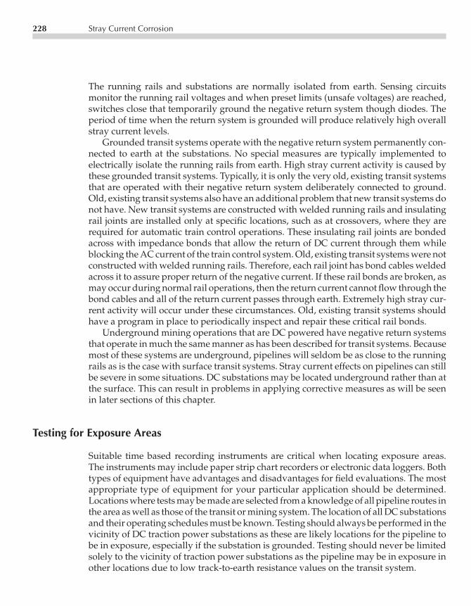
P1: UBICE003-11 CE003-Peabody November 3, 2000 11:58 Char Count= 0
228 Stray Current Corrosion
The running rails and substations are normally isolated from earth. Sensing circuitsmonitor the running rail voltages and when preset limits (unsafe voltages) are reached,switches close that temporarily ground the negative return system though diodes. Theperiod of time when the return system is grounded will produce relatively high overallstray current levels.
Grounded transit systems operate with the negative return system permanently con-nected to earth at the substations. No special measures are typically implemented toelectrically isolate the running rails from earth. High stray current activity is caused bythese grounded transit systems. Typically, it is only the very old, existing transit systemsthat are operated with their negative return system deliberately connected to ground.Old, existing transit systems also have an additional problem that new transit systems donot have. New transit systems are constructed with welded running rails and insulatingrail joints are installed only at specific locations, such as at crossovers, where they arerequired for automatic train control operations. These insulating rail joints are bondedacross with impedance bonds that allow the return of DC current through them whileblocking the AC current of the train control system. Old, existing transit systems were notconstructed with welded running rails. Therefore, each rail joint has bond cables weldedacross it to assure proper return of the negative current. If these rail bonds are broken, asmay occur during normal rail operations, then the return current cannot flow through thebond cables and all of the return current passes through earth. Extremely high stray cur-rent activity will occur under these circumstances. Old, existing transit systems shouldhave a program in place to periodically inspect and repair these critical rail bonds.
Underground mining operations that are DC powered have negative return systemsthat operate in much the same manner as has been described for transit systems. Becausemost of these systems are underground, pipelines will seldom be as close to the runningrails as is the case with surface transit systems. Stray current effects on pipelines can stillbe severe in some situations. DC substations may be located underground rather than atthe surface. This can result in problems in applying corrective measures as will be seenin later sections of this chapter.
Testing for Exposure Areas
Suitable time based recording instruments are critical when locating exposure areas.The instruments may include paper strip chart recorders or electronic data loggers. Bothtypes of equipment have advantages and disadvantages for field evaluations. The mostappropriate type of equipment for your particular application should be determined.Locations where tests may be made are selected from a knowledge of all pipeline routes inthe area as well as those of the transit or mining system. The location of all DC substationsand their operating schedules must be known. Testing should always be performed in thevicinity of DC traction power substations as these are likely locations for the pipeline tobe in exposure, especially if the substation is grounded. Testing should never be limitedsolely to the vicinity of traction power substations as the pipeline may be in exposure inother locations due to low track-to-earth resistance values on the transit system.

P1: UBICE003-11 CE003-Peabody November 3, 2000 11:58 Char Count= 0
Stray Current from Transit or Mining Systems 229
Exposure can be experienced on pipelines which do not come close to a DC substation.If, for example, a pipeline crosses a DC traction system, stray current may be picked upat the point of crossing as trains pass. This stray current may flow in both directions fromthe crossing and discharge at remote locations. If a pipeline parallels a transit line for adistance, but does not approach a DC substation closely, current will be picked up by thepipeline as trains pass the parallel section. This current will be discharged from the endsof the parallel section. In finding its way back to the DC substation, stray current mayjump from pipeline to pipeline at crossings in order to follow the most direct or lowestresistance path. Therefore, a pipeline that is not in close proximity to a transit system maycross a pipeline that is. The pipeline that is close in proximity to the transit system maycarry the stray currents to the pipeline that is not in close proximity. Corrosion damageat these pipeline crossings that are remote from a transit system can be severe. Tests forexposure should be made at such possible points of current interchange. This emphasizesthe need to know the routes of all foreign lines in an area where conducting tests.
Recording voltmeters are used to measure and record pipe-to-earth potentials atlocations selected for test. The potential will be measured to adjacent earth in mostinstances. Changes in the pipe-to-earth potentials are greater per unit of current dischargeon coated lines than on bare lines. Where the pipeline potential becomes more positiveduring periods of stray current activity, current discharge is indicated. Experience withthis type of testing is most helpful in planning the recording instrument test programand when interpreting the data taken.
Figure 11.13 is a representation of the results that may be obtained at a stray currentdischarge area on a pipeline adjacent to a transit system. The chart shows that the pipelineis affected by stray current activity when the transit system is in operation, but that thepipeline only goes into exposure during the morning and afternoon rush hour periods.
−2.0
−1.0
0
+1.0
+2.0
MIDNIGHT 6 AM 6 PM MIDNIGHTTIME-HOURS
NOON
MORNINGRUSHHOUR
AFTERNOONRUSH HOUR
PIP
E T
O C
OP
PE
R S
ULP
HA
TE
PO
TE
NT
IAL-
VO
LTS
Figure 11.13 Pipe-to-earth potential at traction system stray current dischargearea.

P1: UBICE003-11 CE003-Peabody November 3, 2000 11:58 Char Count= 0
230 Stray Current Corrosion
It becomes apparent from a study of the chart that observation of an indicating meterfor any reasonable period of time is not apt to give a true picture of the full rangeof potential variations. The evaluation of the stray current activity indicated on thechart in Figure 11.13 must focus on the time periods when the pipeline is in exposure.The duration of the individual exposures must be determined as well as the expectedimpact on the pipeline itself. If the pipeline goes into exposure for only very limitedtime periods, then the pipeline may not be experiencing corrosion damage and no straycurrent mitigation measures may be necessary.
Recording millivolt meters may be used to measure pipeline current on calibratedpipe spans. Where sufficient test spans exist or can be installed, two or more such record-ing millivolt meters may be used to record the current flow at adjacent test points inareas where exposure is suspected. By comparing the charts taken at any two adjacenttest points, current loss in the section may be detected. Current loss between test pointsmay be determined with indicating millivolt meters also. This necessitates having anobserver at each test point. A series of simultaneous readings are made and comparedto ascertain whether or not current loss is occurring. Although a synchronized timingschedule, typically using computer data loggers, may be used to obtain simultaneousreadings, direct communication (as by cellular phone) is more reliable and should beused to verify that the test equipment is actually synchronized.
When working with bare pipe, carefully conducted current loss surveys will indicatethe point of maximum voltage exposure (by showing where current loss is greatest)unless there is wide variation in soil resistivity. On coated lines, however, the point ofmaximum current discharge can be some distance from the point of maximum voltageexposure. This can happen when the coating at the point of maximum exposure, forexample, is in substantially better condition than at other locations in the area.
Once the general location of the point of maximum exposure has been determined,it may be pinpointed more precisely by the use of X/Y plotters or two indicating volt-meters (two identical voltmeters are required to assure consistency of data). This is doneby correlating the pipe-to-earth potential at the test point with the potential betweenthe pipeline and the transit system negative return. Correlations are made at a seriesof locations through the exposure area. At each location, a number of simultaneousreadings are taken at various degrees of intensity of the stray current effect. Carefullyrecorded data, when plotted, will fall along a generally straight line. The slope of theline is a measure of exposure: the greater the slope, the greater the exposure. The calcu-lated slope at each test point may be referred to as the Beta for that point. The diagramobtained by plotting the slope, or Beta, against the test point locations may be referredto as a Beta Profile or an Exposure Profile. The general procedure is summarized byFigure 11.14.
Because of the possibly very marked and quick stray current variations, it is essentialthat indicating instruments of identical characteristics be used in obtaining simultaneousreadings. Rapid response is necessary. If characteristics are not identical, particularly withregard to response speed, good correlation of simultaneous readings cannot be obtained.It is obvious that a lot of work is involved in taking and plotting data and obtainingslopes at each test point to produce an exposure profile. X/Y plotters are available whichwill record both values simultaneously and show the line of slope. Where much of this

P1: UBICE003-11 CE003-Peabody November 3, 2000 11:58 Char Count= 0
Corrective Measures 231
+ −
D-CSUB-
STATION
OVERHEAD FEEDER
RAILS − +− +VE1 E2V
PIPELINE
987654321
TEST POINTS
SAME INSTRUMENTSET UP FOR EACHTEST POINT
SLOPEDIAGRAM
SLOPE = X/Y
X
Y
E1-
VO
LTS
E2-VOLTS
1.0
0.5
SLO
PE
POINT OF MAX-IMUM EXPOSURE
1 2 3 4 5 6 7 8 9
TEST POINTSTYPICAL PLOT OF SLOPES THROUGH
SUSPECTED EXPOSURE AREA
TYPICAL PLOT OFSIMULTANEOUSREADINGS AT ATEST LOCATION
Figure 11.14 Locating point of maximum stray current exposure.
type of work is to be done, such instruments will save a great deal of time. High inputimpedance and rapid response are essential characteristics to be looked for in selectingsuch a recorder.
CORRECTIVE MEASURES
Transit System Action
One approach to stray current mitigation involves the elimination of excessive straycurrent activity at its source. This involves the assistance of the transit system operator

P1: UBICE003-11 CE003-Peabody November 3, 2000 11:58 Char Count= 0
232 Stray Current Corrosion
and is often only feasible with the newer, nongrounded transit systems. Most transitsystems have a corrosion engineer on staff or a corrosion engineering consultant availableto deal with these types of stray current interference problems. The utility operatorshould request a meeting with the transit system corrosion engineer to review the fielddata and discuss what action is available to the transit system. Typically, the transitsystem engineer will perform track-to-earth resistance and track-to-earth voltage testingin the vicinity of the pipeline to determine if a problem exists on the transit system. If aproblem is found to exist, the transit system will usually make the necessary repairs andthe excessive stray current activity may be eliminated. The typical repairs will includecleaning of wet and dirty trackwork, replacement of damaged track fasteners, removal ofinadvertent contacts between the negative return system and ground, and/or correctionof improper positive system operation. Retesting of the pipeline, after the repair of thetransit system, will have to be performed to verify that the excessive stray current activityhas been mitigated and that any remaining stray current activity is at tolerable levels.
Pipeline Modifications
Another approach to stray current mitigation involves making modifications to thepipeline to reduce its susceptibility to stray currents and to provide a safe means ofstray current discharge. The modification of the pipeline to reduce stray current activitymaintains all control for the stray current measures directly in the hands of the pipelineoperator.
The first consideration for pipeline modification involves the installation of insulatingjoints. The proper placement of insulating joints in a pipeline can dramatically reducethe overall stray current activity on the pipeline by making the pipeline less susceptibleto stray current pickup and discharge. By installing insulators, the pipeline operator isincreasing the overall resistance of the pipe to earth, thereby reducing its tendency topick up stray currents. This approach may require modifications to the CP system for thepipeline to assure that full protection is maintained on the pipeline after the insulatingjoints are installed.
Another possible pipeline modification involves the installation of magnesium an-odes on the pipeline at the locations where the pipeline is going into stray current dis-charge. The magnesium anodes can provide a low resistance discharge point for thestray currents so that no stray current actually discharges directly from the pipeline. Thestray current activity must be carefully re-evaluated after the magnesium anodes areinstalled to verify that the stray current is discharging fully from the anodes. If magne-sium anodes are installed where the pipeline both picks up and discharges stray current,then the installation of diodes with the magnesium anodes may be necessary to assurethat the anodes discharge stray current, but do not collect stray current. The installationof magnesium anodes may be required at insulating joints where stray current may bedischarging around the joints.
Another possible pipeline modification involves the installation of a potentially con-trolled rectifier and impressed current ground bed where the pipeline is going into stray

P1: UBICE003-11 CE003-Peabody November 3, 2000 11:58 Char Count= 0
Corrective Measures 233
EXPOSURE AREAEXPOSURE AREA
POTENTIALCONTROLLEDAUTOMATICRECTIFIER
GROUNDBED
GROUNDBED
A.C.SUPPLY
A.C.SUPPLY
POINT OFMAXIMUM
EXPOSURE
REFERENCEELECTRODE
REFERENCEELECTRODE
POINT OFMAXIMUM
EXPOSURE
PIPELINE D.C. RAILROAD
+
−
+
−
POTENTIALCONTROLLEDAUTOMATICRECTIFIER
Figure 11.15 Use of potential controlled automatic rectifiers for stray current control.
current discharge. The output of the rectifier would automatically adjust itself to supplyadditional CP current to the pipeline when stray current was being discharged. Thiswould maintain acceptable CP levels on the pipeline at all times. This approach is onlyeffective and feasible if the pipeline has a very limited number of areas where the straycurrent is discharging from the pipeline. Figure 11.15 shows a potentially controlledrectifier installation.
The pipeline should be evaluated to determine if its CP system is operating prop-erly. It is possible that the existing CP system would be sufficient to overcome the straycurrent activity if it were operating properly. The repair of defective rectifiers, damagedexternal coatings, defective insulating joints and the removal of any inadvertent con-tacts to grounded structures may sometimes greatly reduce stray current effects andeliminate possible stray current damage. Always make sure that everything on thepipeline is operating as intended and that the CP system is functional before perform-ing any evaluations to determine what additional stray current mitigation measures arerequired.
Stray Current Drainage Bonds
The measure of last resort that may be implemented for stray current mitigation is theinstallation of a drainage bond between the pipeline and the transit system negativereturn system. Figure 11.16 shows a drainage bond installation. The installation of a

P1: UBICE003-11 CE003-Peabody November 3, 2000 11:58 Char Count= 0
234 Stray Current Corrosion
−+
RUNNING RAILSNEGATIVE RETURN
BOND ACROSS HIGHRESISTANCE JOINTS
MOVING CURRENTPICKUP AREA POINT OF MAXIMUM
EXPOSURE
LOAD CURRENT REQUIREDTO OPERATE TRAIN
OVERHEAD POSITIVEFEEDER
D-CSUB-
STATION
PIPELINE BOND CABLE
Figure 11.16 Bond between pipeline and DC substation.
drainage bond should only be considered if all other stray current control (on the transitsystem) and stray current mitigation measures (on the pipeline) prove ineffective. Theinstallation of a stray current drainage bond requires a direct connection between thepipeline and the negative return of the transit system. The connection to the negativereturn is made at a traction power substation if at all possible to avoid interfering withany automatic train control equipment on the running rails. The installation of a drainagebond should safely drain the stray current from the pipeline. However, it will also resultin a decrease in the transit system’s overall negative return resistance-to-earth. This willresult in a significant increase in total stray current activity associated with the transitsystem and will probably result in excessive stray current interference on pipelines thatwere previously being subjected to only minor stray current effects. This is likely to leadto the need for additional stray current drainage bonds and the distribution of the straycurrent over an ever increasing larger area with an increase in the number of utilitiesbeing adversely impacted by the stray current activity.
The bond must have adequate conductivity to remove all stray current and clear theexposure condition. In designing a bond, it should have, ideally, just enough conductivityto clear the exposure. If the conductivity is higher than necessary, more current will bedrained. This may not be harmful to the pipeline to which the bond is connected butwill cause it to become more highly negative to earth than necessary. This may in turnincrease the likelihood of exposure at crossings with other pipelines. If the pipeline beingbonded to the substation is coated, potentials should not be allowed to become morenegative to earth than necessary so that, insofar as possible, coating damage may beavoided.
Although a bond resistance value may be obtained by installing a temporary cableand determining the degree of clearance per ampere drained, the resistance may becalculated using the following expression:
Bond resistance in ohms = (RP−G/Slope)− RP−N (1)

P1: UBICE003-11 CE003-Peabody November 3, 2000 11:58 Char Count= 0
Corrective Measures 235
where:
RP−G is the resistance in ohms between pipeline and ground at point ofmaximum exposure.
Slope is the slope (expressed as a decimal) previously determined atthe point of maximum exposure.
RP−N is the resistance in ohms between pipeline and substationnegative bus.
Resistance values are determined by the ammeter-voltmeter method using an inter-rupted source of DC current connected between the pipeline and substation negativebus. The DC current source used must be of sufficient capacity to override the potentialswings caused by the stray current activity. The average of a number of readings will berequired to obtain reliable data. Taking such readings at a time when the load on the sub-station is at a minimum will facilitate good data. Once the bond cable size is determined,a trial installation is recommended to determine the impacts on other adjacent utilitiesfrom the installation of a bond. This will allow testing to be performed to determine ifother utilities will require a bond to the pipeline or to the transit system. This testingmay determine that a different size bond cable than that originally calculated will berequired. The bond cable that is installed must have sufficient current carrying capacityto handle the maximum current drained without burning out.
A simple bond to a DC substation as discussed is ample where that substation isthe only one supplying current to the traction or mining system. If, however, there areseveral substations on the system and the one to which the bond is connected is lightlyloaded or out of use during part of each 24 hour period, having the bond permanentlyconnected becomes a disadvantage. This is because the direction of current flow in thebond can reverse and feed stray current to the pipeline. This reverse current flow willincrease exposure conditions at other points on the pipeline.
To prevent this reverse current flow, various types of reverse current switches maybe used in the bond cable installed between pipeline and negative bus. These may takethe form of relay-actuated switches which open automatically when the current tendsto reverse. Diodes may also be used to block any reverse current flows. A stray currentdrainage bond should always have some kind of device to block the flow of reversecurrent. In the event of a change in the transit system operations, the bond shouldnot be allowed to carry current directly to the pipeline. If this happens, stray currentwill be discharged from the pipeline at a location remote from the drainage bond. Thiscould result in serious corrosion damage on the pipeline. When reverse current blockingdevices of either type are used, allowances must be made in the bond resistance designfor any voltage drop (effective resistance) interposed by the blocking device.
The installation of bond cables between a pipeline and a DC substation is seldomeasy, particularly in urban locations where a practical route for heavy drainage cablemust be selected. A special problem is associated with underground substations onmining systems. If a bond is unavoidable, it may be necessary to drill a bore hole fromthe surface to the mine gallery where the substation is located. This requires carefulselection of the hole location in cooperation with the mine surveyor, and the drilling of

P1: UBICE003-11 CE003-Peabody November 3, 2000 11:58 Char Count= 0
236 Stray Current Corrosion
a straight hole. Before undertaking such action, however, it is wise to find out how longthe underground substation will remain in its present location. This is because miningsubstations are apt to be moved as mining progresses. If it is found that the substationis to be moved in the near future, the bore hole installation would not be economical.
Underground Corrosion Coordinating Committees
As was discussed under Notification Procedures in the section covering stray currentfrom CP installations, the pipeline corrosion engineer should utilize the services of theunderground corrosion coordinating committees. By attending committee meetings reg-ularly, the engineer will have advance information pertaining to any changes in straycurrent sources or corrective action by others which may have an effect on the engineer’sown system.
Stray Current from Magnetic Disturbances
Occasionally, varying pipe-to-soil potentials and/or pipeline currents will be encoun-tered in areas where there is no known source of man-made stray direct current. Thesepipe-to-soil variations usually are associated with disturbances in the earth’s magneticfield. Such disturbances have been found most active during periods of severe sun spotactivity. Stray current from this source is termed telluric. The reason for the effect onpipelines may be associated with the buildup and collapse of the earth’s magnetic fieldin the area of the pipeline. In an electric generator, voltage is produced by passing aninsulated conductor through a magnetic field in such a manner that the conductor cutsthe magnetic lines of force. Likewise, a voltage is generated on a pipeline due to thevariations in the earth’s magnetic field along the pipeline route.
Telluric effects may be identified with recording instruments. A 24-hour record ofpipeline current or pipe-to-soil potential, if the effect is telluric, will not show any iden-tifiable pattern as is the case when the stray current is of man-made origin. Fortunately,although occasionally intense, telluric current effects on pipelines are seldom of longduration and may not even be localized at specific pickup or discharge areas for anylength of time. For this reason, corrective measures are not often required. Should areasbe found, however, where the condition occurs frequently enough and is of serious inten-sity, corrective measures discussed earlier in the chapter may be adapted to counteractthe telluric effect.
REFERENCES
R. L. Seifert, Practical Interference Current Testing on Underground Metallic Structures, MaterialsProtection and Performance, Vol. 11, 41 October 1972.M. J. Szeliga, ed., Stray Current Corrosion: The Past, Present and Future of Rail Transit Systems,NACE International, Houston, TX, 1994.

P1: FPVCE003-12 CE003-Peabody November 3, 2000 12:0 Char Count= 0
Chapter12Construction Practices
Ronald L. Bianchetti
Areas covered in this section that apply to the overall corrosion control program includepipeline coatings, test points, cased crossings, insulated joints, galvanic and impressedcurrent cathodic protection (CP) installations, and inspection requirements.
PIPELINE COATINGS
Pipeline coatings were detailed in Chapter 2. Although precautions to be observed werediscussed in that chapter, additional points applicable specifically to construction aredescribed below.
Handling Mill Coated Pipe
If mill coated pipe is used, start at the mill to verify that all coating steps are strictlyin accordance with the specifications established. This includes surface preparation,priming, application of specified coating materials, holiday tests and holiday repairs,and yard racking of the coated pipe. Check also to see that the pipe is handled carefullyduring loading out for truck or rail delivery so that coating damage will be at a minimum.Also see that coated pipe lengths are padded adequately and secured solidly on rail carsor trucks so that damage cannot develop under normal shipping conditions. Shippingrequirements should be covered by careful specifications designed to accomplish thedesired result.
If shipping is by rail, the coated pipe either will be transferred from the rail carsdirectly to trucks or will be placed first in field storage and then loaded onto the trucks.Again make sure that the coated pipe is handled and protected with care and arrangefor specifications that will cover every phase of this work.
When trucks arrive at the job site, facilities must be available for placing the coatedpipe on the ground—not dumping it directly from the truck. Coated pipe should not be
237

P1: FPVCE003-12 CE003-Peabody November 3, 2000 12:0 Char Count= 0
238 Construction Practices
placed directly on the ground unless the ground is free of material that could damagethe coating. Preferably it should be placed with skids or supports under the bare pipeends where the coating has been cut back; this is seldom possible, however, becauseof pipe length variation. The best alternative is the use of supports padded properlyto prevent damage to the coating. Check with the coating manufacturer for paddingrecommendations as well as the number of layers permissible in the pipe pile.
Lengths of mill coated pipe should be handled with belt slings or end hooks. Chainsor cables around the coated pipe must not be permitted. Belt slings must be wide enoughso that they will bear the full pipe weight without distorting the coating. End hooks (oneto engage each end of the pipe using a cable sling and spreader) must be designed sothat the pipe ends will not be distorted by their use. If a length of coated pipe is handledwith a single belt sling, its swing should be restricted with ropes or other suitable meansto prevent accidental swinging into equipment with attendant coating damage.
When coated pipe is taken from the ground after stringing for lining up and weldinginto the pipeline, it usually will be laid up on skids under coated portions to free theends for welding. Suitable padding must be used between the coating and timber skidsto avoid damage.
Pipe Coating over the Ditch
In addition to making sure that the coated pipe is handled as carefully as described formill coated pipe, the corrosion engineer must verify that the coating application is instrict accordance with tight specifications as was discussed in Chapter 2.
This applies to every phase of pipe cleaning, priming and application of coatingmaterials such as cold applied tapes, wax coatings, heat-shrink sleeves, and wraps. Besure materials are handled carefully in the field. They must be kept free of dirt and otherforeign matter. Wrapping material must be kept dry.
The manufacturer of coating materials should have a technical advisor on a pipelineproject. If problems develop under unusual application conditions, the advisor shouldbe consulted at once. Advisors are interested in how their material performs and will beable to recommend application or material modifications to meet the special situationencountered.
Holiday Detection and Repair
Refer to Chapter 2 for further information on the use of holiday detectors. This is an im-portant part of the over-all coating procedure. The corrosion engineer should be assuredthat detector operators are trained properly in the use of the equipment and that theyare using appropriate procedures to verify adequate detector performance at all times.
Because the holiday detector test usually is the last opportunity to verify coatingintegrity before it is backfilled, this test must be thorough with all holidays well markedfor repair. If the coated pipe is laid up on skids prior to lowering into the ditch, be surethat the pipe is checked after lifting from each skid.

P1: FPVCE003-12 CE003-Peabody November 3, 2000 12:0 Char Count= 0
Test Point Installations 239
The holiday repair crew is as important as the holiday detection crew. Those makingsuch repairs must be trained to repair coating defects properly and apply the repairmaterials in such fashion that the repaired holiday will be as strong, electrically andmechanically, as the original coating. Preparation includes removing broken and dis-bonded material and, for best performance when working with enamel or other thickcoatings, feathering the edges of the break with a draw knife or equivalent tool. Thisassures a better bond between the repair materials and the original coating. If there is anouter wrap, it must be removed from around the break to obtain good bonding of repairmaterials at the overlap. The repair materials themselves must be handled carefully andin accordance with good coating practice.
Good Practices Save Money
Good coating construction practices produce results. Insistence on good coating pro-cedures from the beginning of construction should be the function of the responsiblecorrosion engineer.
TEST POINT INSTALLATIONS
Test points are the best means of electrically examining a buried pipeline to determinewhether or not it is cathodically protected as well as making other tests associated withcorrosion control work. Types of test points needed have been mentioned in precedingchapters. To serve their purpose over the years, these test points must be convenient touse and must be so constructed to minimize future damage to the test station.
Types of Test Points
Test point types by function are illustrated in Figure 12.1. The types shown are not neces-sarily representative of any particular standard but are intended to represent the varietythat may be encountered. A color code is shown to illustrate a system whereby leadsmay be identified. Whatever color code is adopted should be made standard throughoutyour pipeline system.
The two-wire potential test point is the one used most frequently. Two wires make itpossible to check pipe-to-earth potential with one while test current is being applied tothe line (if desired) using the other.
The four-wire insulated joint test point permits measuring pipe-to-earth potentialson each side of an insulated joint. The second pair of heavier gauge wires are availablefor inserting a resistance or solid bond across the insulated joint if necessary.
The four-wire calibrated line current test point permits accurate measurement ofpipeline current flow as discussed in Chapter 5.
The six-wire combination insulated joint and line current test point is useful, particu-larly at terminal insulated flanges, because it permits positive measurement of current

P1: FPVCE003-12 CE003-Peabody November 3, 2000 12:0 Char Count= 0
240 Construction Practices
MEASURED SPAN
4-WIRE CALIBRATEDLINE CURRENT TEST POINT
BLACK
BLACK
WHITEWHITE WHITE
BLACKYELLOW
POTENTIALTEST POINT
INSULATED JOINTTEST POINT
FLOW FLOW
INNER WIRES HEAVIERGAUGE THANOUTER WIRES
BLUE ORGREEN
MEASURED SPAN3 3
WHITEBLACKYELLOW
BLUE ORGREEN
WIRES CLOSESTTO JOINT TO BEHEAVIER GAUGE
FLOW
COMBINATION INSULATED JOINTAND LINE CURRENT TEST POINT
INDICATING VOLTMETERTEST POINT
WHITE RED
MOMENTARYCONTACTSWITCH
PACKAGED COPPER COPPER SULFATE (CSE) REFERENCEELECTRODE
BLACK
HEAVIER WIREWHITE
FOREIGN LINE CROSSINGTEST POINT
GALVANIC ANODETEST POINT
BLACK
WHITERED
ANODES
SHUNT
Figure 12.1 Typical types of test station.
flow through an insulated flange should the flange become totally or partially shortedfor any reason. Likewise, it will measure the current flowing through a solid or resistancebond should such measurement be necessary. One heavier gauge wire is provided oneach side of the insulated joint for bonding purposes (if required).
An indicating voltmeter test point is installed at key points on some systems. Thesemeters may be read by operating personnel on a routine basis and the indicated valuesrecorded and reported to the corrosion engineer. As shown in Figure 12.1, a voltmetermay be connected between the pipe and a reference electrode suitable for undergroundservice.

P1: FPVCE003-12 CE003-Peabody November 3, 2000 12:0 Char Count= 0
Test Point Installations 241
The foreign line crossing test point provides two wires to each line. One wire isused for potential measurements or other tests as required while the other (the heaviergauge wire) is available for installing a bond when needed. It should be noted thattest wires should never be attached to another company’s pipeline unless the pipelineowner authorizes it. Further, many companies will allow such attachments only if madeby their own personnel or if their own representatives are present while the attachmentsare being made.
The galvanic anode test point is typically used primarily in connection with anodesat one location. Such a test point is shown in greater detail in Chapter 9 (Figure 9.9).
Test Point Construction
Test points should be located where they will be as convenient as practical for the corro-sion engineer. While some type of post mounting is preferable, in some areas test pointsmay have to be in grade level boxes or even buried.
Typical methods of mounting above-ground test points are illustrated by Figure 12.2.Terminal boxes used should be of heavy cast metal construction to resist gunfire—test points in rural areas become convenient targets. Many terminal boxes and match-ing terminal blocks are available commercially. Terminal blocks obtained to fit thebox selected should have heavy studs (at least 0.25 in) of solid brass (may be nickel or
18" × 18" × 6"CONCRETESLAB CASTAROUND PIPEAT GRADELEVELCONDUIT
BUSHING
SELF-SUPPORTEDCONSTRUCTION
POST-SUPPORTEDCONSTRUCTION
VENT-PIPE-SUPPORTEDCONSTRUCTION
CONDUITBUSHING
3/4" ORLARGERGALVANIZEDSTEELCONDUIT
TACK WELDSTRAP TOVENT ORTACK WELDCONDUIT TOVENT.
TERMINAL BOX
4" × 4" × 6" TREATEDWOOD POST
TERMINAL BOX(COVER REMOVED)
REDUCINGFITTINGS IFNECESSARY
2" GALVANIZEDSTEEL CONDUIT
3 - 6" 3 - 6"
2 - 6"
18"
18"
3"
6"
18" TO24"
VENT PIPE
Figure 12.2 Typical types of above grade test stations.
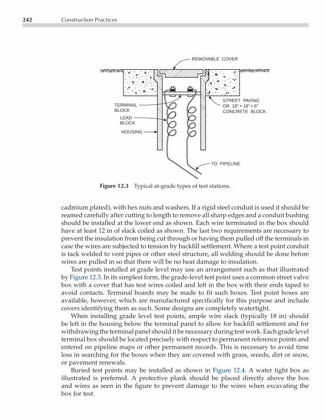
P1: FPVCE003-12 CE003-Peabody November 3, 2000 12:0 Char Count= 0
242 Construction Practices
TERMINALBLOCK
LEADBLOCK
HOUSING
REMOVABLE COVER
STREET PAVINGOR 18" × 18" × 6"CONCRETE BLOCK
TO PIPELINE
Figure 12.3 Typical at-grade types of test stations.
cadmium plated), with hex nuts and washers. If a rigid steel conduit is used it should bereamed carefully after cutting to length to remove all sharp edges and a conduit bushingshould be installed at the lower end as shown. Each wire terminated in the box shouldhave at least 12 in of slack coiled as shown. The last two requirements are necessary toprevent the insulation from being cut through or having them pulled off the terminals incase the wires are subjected to tension by backfill settlement. Where a test point conduitis tack welded to vent pipes or other steel structure, all welding should be done beforewires are pulled in so that there will be no heat damage to insulation.
Test points installed at grade level may use an arrangement such as that illustratedby Figure 12.3. In its simplest form, the grade-level test point uses a common street valvebox with a cover that has test wires coiled and left in the box with their ends taped toavoid contacts. Terminal boards may be made to fit such boxes. Test point boxes areavailable, however, which are manufactured specifically for this purpose and includecovers identifying them as such. Some designs are completely watertight.
When installing grade level test points, ample wire slack (typically 18 in) shouldbe left in the housing below the terminal panel to allow for backfill settlement and forwithdrawing the terminal panel should it be necessary during test work. Each grade levelterminal box should be located precisely with respect to permanent reference points andentered on pipeline maps or other permanent records. This is necessary to avoid timeloss in searching for the boxes when they are covered with grass, weeds, dirt or snow,or pavement renewals.
Buried test points may be installed as shown in Figure 12.4. A water tight box asillustrated is preferred. A protective plank should be placed directly above the boxand wires as seen in the figure to prevent damage to the wires when excavating thebox for test.

P1: FPVCE003-12 CE003-Peabody November 3, 2000 12:0 Char Count= 0
Test Point Installations 243
PIPELINE
WATER TIGHT BOX WITHTERMINAL BOARD
TEST WIRES WITHSUFFICIENT SLACKTO PERMIT BRINGINGTEST BOX TO SURFACEFOR TESTS
WATER TIGHTSTUFFING BOX
TREATED WOOD PLANKABOVE BOX AND WIRES
BELOW FLOW DEPTH
Figure 12.4 Typical buried type of test stations.
Because of the time required for excavating buried test points, they should be usedonly when there is no alternative. Where possible, it may be preferable to extend leadsseveral hundred feet to a point where an above-ground test point can be installed. Thistest site must be located precisely with respect to permanent landmarks and the locationinformation recorded where it will be available when tests are made.
Test Wires and Pipeline Connections
Test wires for potential measurements are sized for mechanical strength rather than elec-trical requirements. As a guide, No. 12 American Wire Gauge (AWG) single conductorstranded wire with 600 V insulation suitable for this service under normal conditionsshould be used. Such wire may be procured in the various colors needed for test pointcolor coding. For heavier gauge wire shown in some of the sketches in Figure 12.1, No. 6or No. 4 AWG wire is satisfactory unless the test points are in severe transit or areas ofstray current where the wires may carry very large currents. Wire sizing in these caseswill depend on experience in similar situations.
If it should be necessary to splice test wires during installation, twisted or boltedsplices should not be permitted because they may develop high resistance in time.A soldered splice is preferable, using a good grade of 60–40 lead-tin solder with a

P1: FPVCE003-12 CE003-Peabody November 3, 2000 12:0 Char Count= 0
244 Construction Practices
BARED END OF TESTWIRE INSERTED INMOLD. MAY REQUIREREINFORCING SLEEVE.SEE MANUFACTURERSINSTRUCTIONS.
FLINT GUN FORIGNITING POWDER
GRAPHITE MOLD.SEE MANUFACTURERSDATA FOR SIZE AND STYLE
REMOVE COATING AND CLEANPIPE TO BRIGHT STEEL WITH FILEWHERE CONNECTION IS TO BE MADE
COATING MUST COMPLETELYSURROUND ALL EXPOSEDCOPPER NO VOIDS AREPERMITTED.
REMOVE EXCESSSLAG AND TESTWELD WITH HAMMERFOR GOOD BOND.REMAKE IF FOUNDDEFECTIVE.
COATING PATCH OVERLAPPINGEXISTING COATING ANDINSULATION ON WIRE.
POWDER CHARGE
Figure 12.5 Wire connections to pipe.
noncorrosive flux. The splice should be insulated by rubber and plastic tape with thewrapping overlapping the wire insulation sufficiently to render it water-tight.
Test point wires should be so placed that they will not be subjected to excessivestrain and damage during backfill operations. Care taken in installation will avoid wirebreakage requiring expensive re-excavation for repair. Damage of this nature is mostlikely to occur where wires are extended along the pipe (as are remote wires for a 4-wirecalibrated test point) to reach the test point terminal box. In such instances, the wiresmay be placed under the pipe as far as they will go before backfilling or they may be runalong the top of the pipe and adhered to the pipe with a continuous strip of self-adhesivetape that will also serve to give the wires added mechanical protection.
Permanent low resistance connections are required between test wires and pipeline.Usually these are made using an exothermic welding processes. Currently, practice favorslimiting the size of the powder charges to 15-gram when working on high pressure steellines to minimize localized stresses in the pipe steel caused by the welding heat. The15-gram charge is adequate for smaller wire sizes. For sizes larger than No. 4, it may benecessary to separate the wire stranding into two or more bundles and powder weldeach bundle to the pipe separately. Coating repair is important after wire connections aremade. Manufacture literature should be referenced to determine proper powder chargefor type and size of pipeline. The essential features of exothermic weld connections andcoating repair are shown in Figure 12.5.
Planning a Test Point Location
Prior to construction, the corrosion engineer should study the proposed route and de-termine the number and types of test points needed. The location and type designation
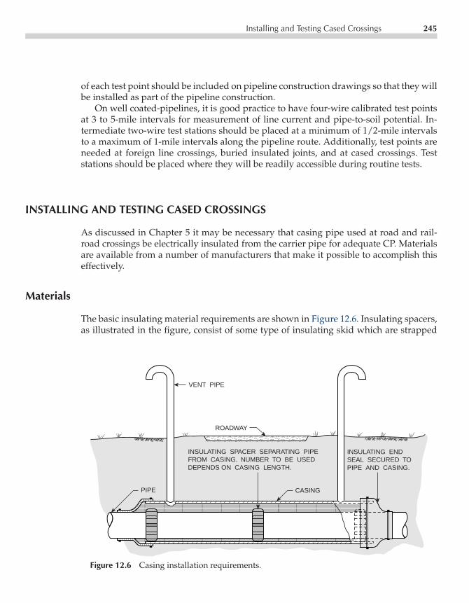
P1: FPVCE003-12 CE003-Peabody November 3, 2000 12:0 Char Count= 0
Installing and Testing Cased Crossings 245
of each test point should be included on pipeline construction drawings so that they willbe installed as part of the pipeline construction.
On well coated-pipelines, it is good practice to have four-wire calibrated test pointsat 3 to 5-mile intervals for measurement of line current and pipe-to-soil potential. In-termediate two-wire test stations should be placed at a minimum of 1/2-mile intervalsto a maximum of 1-mile intervals along the pipeline route. Additionally, test points areneeded at foreign line crossings, buried insulated joints, and at cased crossings. Teststations should be placed where they will be readily accessible during routine tests.
INSTALLING AND TESTING CASED CROSSINGS
As discussed in Chapter 5 it may be necessary that casing pipe used at road and rail-road crossings be electrically insulated from the carrier pipe for adequate CP. Materialsare available from a number of manufacturers that make it possible to accomplish thiseffectively.
Materials
The basic insulating material requirements are shown in Figure 12.6. Insulating spacers,as illustrated in the figure, consist of some type of insulating skid which are strapped
ROADWAY
VENT PIPE
INSULATING SPACER SEPARATING PIPEFROM CASING. NUMBER TO BE USEDDEPENDS ON CASING LENGTH.
CASING
INSULATING ENDSEAL SECURED TOPIPE AND CASING.
PIPE
Figure 12.6 Casing installation requirements.

P1: FPVCE003-12 CE003-Peabody November 3, 2000 12:0 Char Count= 0
246 Construction Practices
around the pipe through the casing at specific intervals. The various commercially avail-able types of casing insulators range from all-plastic types to models having insulatedblocks secured to steel bands (which may be rubber or plastic lined). Skids should beevenly spaced (typically 10 ft max), so that when the carrier pipeline is pulled into thecasing, the end insulating spacers will be close to the casing end as shown in the Figure12.6. Follow manufacturer’s recommendations for the number and size of insulatingspacers. Top quality materials and careful attention to installation are essential, sincestresses on the insulator during installation can be very large. This is particularly truewhen working with the larger pipe sizes at long-cased crossings. If, during the pulling-inoperation, a casing insulator is by accident snagged badly on the casing end, it shouldbe replaced before continuing the installation. After pulling the pipe into final position,if the end insulators are not close to the casing end (such as within 3 ft) additionalspacers should be slid into position at the casing ends to maintain positive electricalseparation.
End seals shown in the Figure 12.6 are commercially available in various designs.Most designs are arranged to provide a tight, yet flexible, seal between pipe and casing,and most seals are watertight. The style illustrated is typical of synthetic rubber sleevessized to fit the pipe and casing and strapped to them.
The casing must be prepared properly before the carrier pipe is pulled into it. Weldsshould be smooth on the inside to prevent damage to insulating spacers. The casingneeds to be straight and in round so the carrier pipe, with spacers affixed, can be pulledin without binding. All debris must be removed. If vent pipes are set after the carrierpipe is pulled, burning a hole in the casing may damage the carrier pipe coating, andif the coupon resulting from cutting the hole is allowed to fall into the casing, a shortcircuit from pipe to casing could result. All welding and hole burning should be donebefore pulling the carrier pipe.
Test Method for Cased Crossings
After a cased crossing has been completed, it should be checked for adequate insulationbefore backfilling. Defects can be repaired at that time at a lesser cost than following thecompleted pipeline installation.
A method of testing cased crossings on completed pipelines is to compare the pipelinepotential to soil with the casing potential to soil (electrode at the same location for bothtests). A difference in the readings is a qualitative indication of satisfactory insulationbetween the two pipes. Details of this testing procedure are found in Chapter 5.
Do not use a welding generator to test casing insulation during construction by con-necting it between the pipe and casing. If the casing is insulated properly, the generatorwill not pass current and no harm will be done. If, however, there should be a short, suf-ficient current may flow to cause a burning effect on the pipe, which could be dangerousin the case of high pressure lines.

P1: FPVCE003-12 CE003-Peabody November 3, 2000 12:0 Char Count= 0
Installing and Testing Cased Crossings 247
TEST POINTTERMINALBLOCKS
BLACKBLACK
BLACK
WHITE
WHITE
BLUEOR
GREEN
BLUEOR
GREENWHITE
TWO-VENT CASINGS(1)
ONE-VENT CASINGS(2)
NO-VENT CASINGS(3)
Figure 12.7 Casing test point installations.
Cased Crossing Test Points
The ease with which cased crossings may be tested depends on the type of test pointinstalled. Some suggestions on casing test points are included in Figure 12.7. Althoughvent pipes may be used in Cases (1) and (2) to indicate whether or not the casing is shortedby using the potential method described above, resistance measurements cannot be madefor quantitative results and, if a contact exists, little can be done to locate the fault. To testthe nonvented casing (Case 3), test wires are required for routine tests to avoid havingto use probe rods to contact the casing.
The four-wire test points (vent pipe serves as one wire in Cases 1 and 2) permitaccurate resistance measurements. The additional wire, vent pipe, or probe rod contactat the opposite end of the casing makes it possible to locate the position of a short circuit,should one develop, as discussed in the next section.
Locating Short Circuits in Casings
If a cased crossing becomes shorted in service, being able to identify by testing wherethe short circuit is located, will save much time and money. This testing can be doneas illustrated in Figure 12.8. As shown in the figure, battery current measured withan ammeter is passed between the pipe and casing. This current will flow along the

P1: FPVCE003-12 CE003-Peabody November 3, 2000 12:0 Char Count= 0
248 Construction Practices
+
+
−
+ −
A
MV
CASING SHORT CIRCUIT
PIPE
VENT PIPE, TESTWIRE, OR PROBE
TEST BATTERYAND AMMETER
Figure 12.8 Casing short location.
casing to the point of short circuit where it will transfer to the pipe and return to thebattery. A millivoltmeter connected between the two ends of the casing will indicate avalue dictated by the measured current flowing through the casing resistance within thecasing length, which the current actually flows through. The casing size and thickness,or weight per foot, must be known so that its resistance can be estimated using Table 5.3in Chapter 5.
As an example, assume that the casing in Figure 12.8 is 26-inch pipe, 0.375-in wallthickness and that the span bridged by the millivoltmeter connection is 80 ft. The resis-tance per foot is 2.82 × 10⁻⁶ ohms per foot. The resistance of the 80 ft span would be225.6× 10−6 ohms. If the battery current flowing is 10 A and the millivoltmeter reading(corrected for lead resistance) is 1.6 mV, the distance traversed by the current would bethe following:
Length = 1.6× 10⁻³ V10 A× (2.82× 10−6) ohms/ft
= 57 ft
The short circuit is 57 ft to the right of the voltmeter connection from the left hand endof the casing.
If a short circuit is found more than a few feet in from the ends of the casing (as inthe example), it may be very difficult or impractical to clear. Fortunately, many shortsare found at the casing ends where they may be cleared without too much trouble.
In some instances if care is not exercised in placing test leads, an apparent defectivecasing is actually a short circuit between one of the pipeline test leads and either thecasing or vent pipe. Test lead shorts can result if the test wires are wrapped around thevent pipe and subsequently subjected to enough strains to cut through the insulation onthe wire.

P1: FPVCE003-12 CE003-Peabody November 3, 2000 12:0 Char Count= 0
Insulated Joints 249
INSULATED JOINTS
Insulated joints are almost always required in cathodically protected piping systems.On transmission lines, for example, they are used to separate the pipeline electricallyfrom terminal facilities and pumping systems. They may be used also to divide theline into sections so that failure of CP systems or development of contacts with otherstructures or sections of the pipeline will reduce the loss of protection to an adjacentsection. These sections may be reasonably long under normal conditions with distancesof 25 to 50 mi being satisfactory. If, however, there are areas where stray currents frommining, traction, or other systems are a problem, closely spaced insulating joints may behelpful in controlling stray current pickup and discharge.
The corrosion engineer should examine proposed construction plans to be sure thatadequate provision has been made for placement of insulating joints. The location ofinsulated joints in such areas will depend on the engineer’s knowledge or investigationof areas where stray current influence may be expected.
In planning points of insulation, care must be taken that all possible current pathsare insulated. For example, 30 in main line with an insulated flange at a line terminus,can be rendered ineffective by an noninsulated quarter inch instrument line bypassingthe flange. Either insulated flanges, or reassembled insulating assemblies, can be usedfor high pressure line work.
In distribution system piping work, insulated joints maybe used to separate the sys-tem into smaller areas for CP purposes. The size of the areas planned will depend on theamount of underground congestion with other pipeline facilities. In downtown sectionswhere underground facilities are dense, individual insulated areas may be limited toa few square blocks. In outlying areas where underground congestion is not great, theinsulated areas may be much larger. Separation of areas facilitates maintenance troubleshooting in the event of contact development.
Field assembled or preassembled insulated flanges, or insulated mechanical jointsmay be used on distribution mains and large service lines. Residential size service linesmay be insulated at the meter with various commercially available devices such asinsulating bushings, unions, meter bars, meters with insulating swivels, and so forth.Service insulation at the main (if necessary) may be by insulating main tapping fittings,bushings, mechanical couplings, and other kinds of insulation.
Insulated Flanges
The general features of the usual insulated flange assembly are illustrated by Figure 12.9.Flange insulating kits are available from corrosion control supply companies to fit allstandard sized flanges. Standard flange bolt holes are 0.125 in larger than standard bolts.Full length insulating sleeves, as shown in the figure, will fit satisfactorily if flanges arealigned properly.
If it is necessary to insulate an existing flange without taking the line out of service, thismay be done if the existing gasket is a reasonably good insulating material. Metallized or
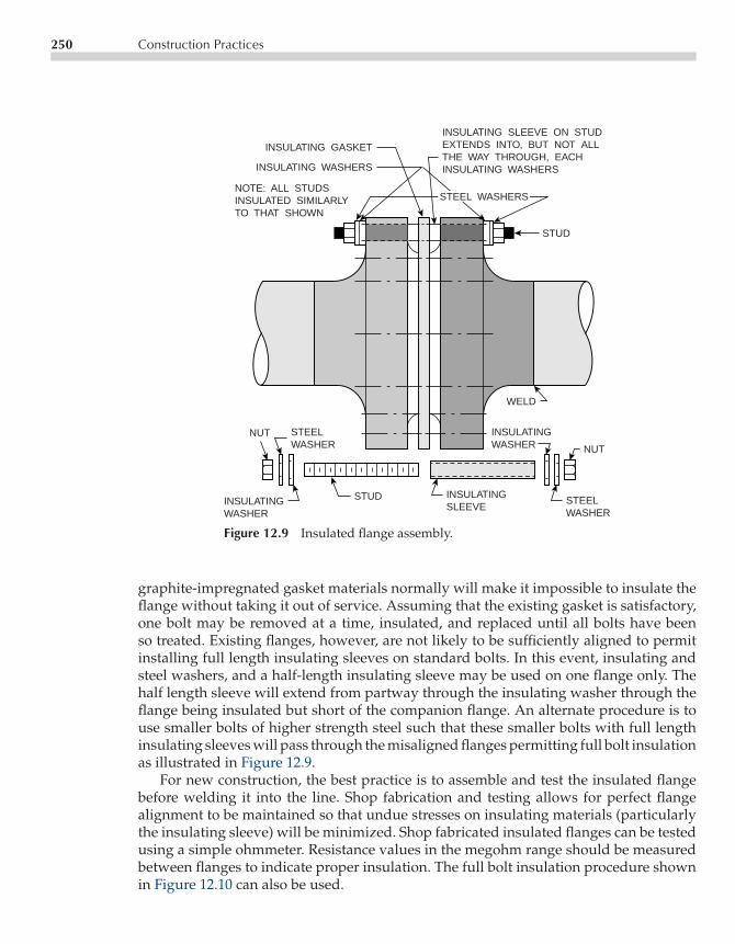
P1: FPVCE003-12 CE003-Peabody November 3, 2000 12:0 Char Count= 0
250 Construction Practices
INSULATING GASKET
INSULATING WASHERS
INSULATING SLEEVE ON STUDEXTENDS INTO, BUT NOT ALLTHE WAY THROUGH, EACHINSULATING WASHERS
STEEL WASHERS
STUD
NOTE: ALL STUDSINSULATED SIMILARLYTO THAT SHOWN
STEELWASHER
INSULATINGWASHER
NUT
STUD INSULATINGSLEEVE
STEELWASHER
NUT
INSULATINGWASHER
WELD
Figure 12.9 Insulated flange assembly.
graphite-impregnated gasket materials normally will make it impossible to insulate theflange without taking it out of service. Assuming that the existing gasket is satisfactory,one bolt may be removed at a time, insulated, and replaced until all bolts have beenso treated. Existing flanges, however, are not likely to be sufficiently aligned to permitinstalling full length insulating sleeves on standard bolts. In this event, insulating andsteel washers, and a half-length insulating sleeve may be used on one flange only. Thehalf length sleeve will extend from partway through the insulating washer through theflange being insulated but short of the companion flange. An alternate procedure is touse smaller bolts of higher strength steel such that these smaller bolts with full lengthinsulating sleeves will pass through the misaligned flanges permitting full bolt insulationas illustrated in Figure 12.9.
For new construction, the best practice is to assemble and test the insulated flangebefore welding it into the line. Shop fabrication and testing allows for perfect flangealignment to be maintained so that undue stresses on insulating materials (particularlythe insulating sleeve) will be minimized. Shop fabricated insulated flanges can be testedusing a simple ohmmeter. Resistance values in the megohm range should be measuredbetween flanges to indicate proper insulation. The full bolt insulation procedure shownin Figure 12.10 can also be used.

P1: FPVCE003-12 CE003-Peabody November 3, 2000 12:0 Char Count= 0
Insulated Joints 251
MV+−
+−STORAGE BATTERY
Figure 12.10 Shop testing of Insulating Flanges.
Testing Insulated Joints
When an insulated joint is placed in a pipeline with a substantial amount of pipe oneither side of the joint, a simple resistance measurement across the joint may read justa few ohms (or even a fraction of 1 ohm), even though the joint resistance was severalmillion ohms just prior to installation. This method should not be used. The resistancemeasured with the joint in place consists of two parallel resistances: (1) the joint resistanceand (2) the resistance to earth of the pipeline on one side of the joint plus the resistanceto earth of the pipeline on the other side of the joint. The resistance measured across ajoint, then, (even with perfect joint insulation) will be governed predominantly by theamount of pipe on either side of the joint, the quality of coating (if any), and the averagesoil resistivity along the pipelines.
More indicative testing of insulated joint effectiveness involves interrupting theCP current source (or test current applied from a temporary d.c. source) on one sideof the insulated joint and measuring the potential to a remote copper sulfate elec-trode. If the joint is effective, the potential on the side with the CP source will changewith a positive shift as the current source is interrupted. The unprotected side willremain constant or move in the negative direction. If the measurements are made toa close electrode over or alongside the insulated joint additional information may begained. For example, if the pipe on the unprotected side swings in the positive directionwhen the interrupter turns the current source ON (even though there may have beenlittle or no change with respect to the remote electrode), it is an indication that current isflowing through the earth around the insulated flange. This may be a result of defective

P1: FPVCE003-12 CE003-Peabody November 3, 2000 12:0 Char Count= 0
252 Construction Practices
coating or excessive voltage drop across the flange. Another test is to utilize an insulatortester, which is commonly available. These instruments allow direct measurement of theinsulating flange integrity.
If an insulated flange is found defective, it may be possible to repair it without takingthe line out of service. This depends on whether the insulating gasket is shorted across orwhether it is an insulated bolt sleeve that is broken down. If it is the latter, the shorted boltmay be removed and the insulation replaced. Determining where the trouble is can be ac-complished by checking each bolt electrically. If flange bolts are fully insulated per Figure12.9, an insulator tester should be used to check resistance between pipeline and each bolt.Bolts that are shorted will have zero or low resistance to the pipe. If all bolts have a highresistance to the pipe, a shorted gasket is probably the problem. This assumes that anypossible bypassing piping on each side of the flange has been identified and insulated.
In the case of a shorted insulated flange having bolts insulated on one side only, theohmmeter test will not be acceptable because all bolts will have low resistance to thepipe. Use an insulator checker to identify whether the bolts are shorted or the flangesare shorted.
Grounding Cells for Insulated Joints
Protective devices may be required where insulated joints are subject to damage fromlightning-initiated high potential surges. This may be more probable where pipelinesclosely parallel high voltage electric transmission lines as when a pipeline is installed inthe same right-of-way. In such instances, a lightning-initiated fault may cause very highvoltages to be induced in the pipeline. If these high voltages are developed across aninsulated joint they may cause the joint to arc the current from the lightning flow for ashort time. Typically insufficient energy (except in rare cases) is expended to cause thejoint to weld across the flange.
Standard lightning arresters may be used effectively. A voltage rating should beselected that will provide adequate protection for the insulation level in the insulatingjoint being used. Arresters having too high a voltage rating might not divert the highpotential appearing across the joint before the insulation fails.
Another protective measure is the grounding cell which combines voltage surge pro-tection with a degree of CP on the unprotected side of the insulating joint. A groundingcell may be constructed as shown, in principle, in Figure 12.11.
Constructed with zinc anodes as illustrated in Figure 12.11, a grounding cell willhave a value of resistance between the two closely-spaced anodes depending on theresistivity of the chemical backfill being used. For a properly installed grounding cell,this resistance should be in the range of 0.2 to 0.5 ohms (depending on the backfill used).In the event of a high potential surge, the cell will conduct and the voltage drop acrossthe insulated joint will be limited to 200 to 500 V per thousand amperes of fault currentflow. Where very heavy fault currents are anticipated, four anode cells (cross-connectedas shown in the detail of Figure 12.11) may be used. These have a lower cell resistance,which limits further the voltage build-up across the insulated flange.
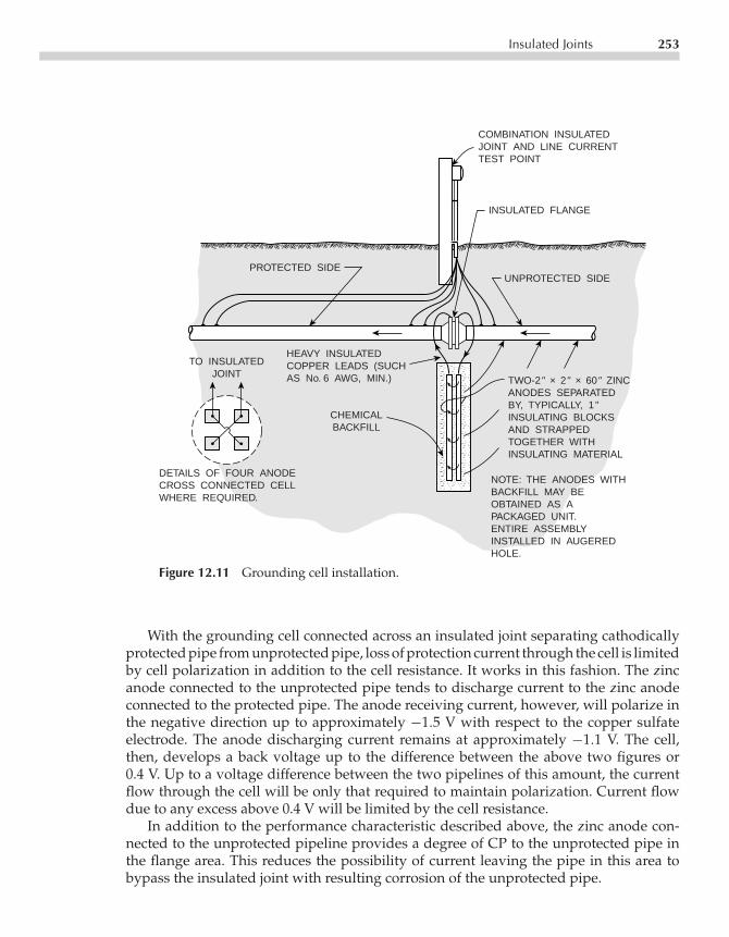
P1: FPVCE003-12 CE003-Peabody November 3, 2000 12:0 Char Count= 0
Insulated Joints 253
COMBINATION INSULATEDJOINT AND LINE CURRENTTEST POINT
INSULATED FLANGE
PROTECTED SIDEUNPROTECTED SIDE
TO INSULATEDJOINT
DETAILS OF FOUR ANODECROSS CONNECTED CELLWHERE REQUIRED.
CHEMICALBACKFILL
HEAVY INSULATEDCOPPER LEADS (SUCHAS No. 6 AWG, MIN.) TWO-2" × 2" × 60" ZINC
ANODES SEPARATEDBY, TYPICALLY, 1"INSULATING BLOCKSAND STRAPPEDTOGETHER WITHINSULATING MATERIAL
NOTE: THE ANODES WITHBACKFILL MAY BEOBTAINED AS APACKAGED UNIT.ENTIRE ASSEMBLYINSTALLED IN AUGEREDHOLE.
Figure 12.11 Grounding cell installation.
With the grounding cell connected across an insulated joint separating cathodicallyprotected pipe from unprotected pipe, loss of protection current through the cell is limitedby cell polarization in addition to the cell resistance. It works in this fashion. The zincanode connected to the unprotected pipe tends to discharge current to the zinc anodeconnected to the protected pipe. The anode receiving current, however, will polarize inthe negative direction up to approximately −1.5 V with respect to the copper sulfateelectrode. The anode discharging current remains at approximately −1.1 V. The cell,then, develops a back voltage up to the difference between the above two figures or0.4 V. Up to a voltage difference between the two pipelines of this amount, the currentflow through the cell will be only that required to maintain polarization. Current flowdue to any excess above 0.4 V will be limited by the cell resistance.
In addition to the performance characteristic described above, the zinc anode con-nected to the unprotected pipeline provides a degree of CP to the unprotected pipe inthe flange area. This reduces the possibility of current leaving the pipe in this area tobypass the insulated joint with resulting corrosion of the unprotected pipe.
P1: FPVCE003-12 CE003-Peabody November 3, 2000 12:0 Char Count= 0
254 Construction Practices
Where higher cell back voltage is desired, other materials may be used. High siliconcast iron, for example, polarizes in both the negative and positive direction and candevelop cell potentials in the order of 2 V or more. If used at an insulated joint separatingprotected and unprotected pipe, however, the high silicon cast iron anode connected tothe unprotected pipe is polarized in the positive direction and will tend to draw currentfrom the unprotected pipe (and corrode) rather than provide a measure of CP as is thecase when zinc is used. This can be overcome by using a high resistance container for thecell package (with, however, provision for entry of soil moisture to keep the chemicalbackfill wet) plus the installation of a local galvanic anode on the unprotected pipe atthe insulated joint.
ISP/Polarization Cells
Isolation surge protectors (ISP) and polarization cells are devices that provide excellentgrounding and protection for insulating joints. ISP are electronic mechanisms that whenplaced across an insulating flange block DC current flow and allow AC current to flow.Due to the devices’ ability to pass AC current during normal operational, ground faultconditions or lightning strikes, the insulating joint is protected and more importantly thesafety of personnel is assured. Since ISP are electronic devices they can automatically resetfollowing a fault condition. Although these devices are more expensive than groundingcells, they provide superior protection. A variety of companies manufacture them andcan provide technical support for your particular needs.
GALVANIC ANODE INSTALLATIONS
Although typical galvanic anode installations have been described in Chapter 9, thefollowing pertains to construction practices.
Wire and Connections
All buried wire interconnecting galvanic anodes with the pipeline are cathodically pro-tected. For this reason, insulation level on wire is not critical, but the insulation shouldbe a material which can be expected to resist deterioration under service conditions.Connections between individual anode leads and header wire should be insulated bytaping with at least one half-lapped layer of rubber tape and one half-lapped layer ofself-adhesive plastic tape (or equivalent insulation) with the joint insulation overlappingthe wire insulation. The copper wire connection to the steel main is the most critical inso-far as insulation is concerned. At this point, all copper at the connection must be coatedcompletely to avoid the possibility of a shielded copper-steel corrosion cell. All connec-tions must be permanently low resistance. Any gradual development of joint resistancewill reduce anode output. Permanent connection such as soldered joints (lead-tin solderor silver solder) or exothermic-welded connections are reliable.

P1: FPVCE003-12 CE003-Peabody November 3, 2000 12:0 Char Count= 0
Cathodic Protection System Installations 255
Anode Backfill
The chemical backfill in packaged galvanic anodes will take up moisture slowly evenif saturated with water after placing in the auger hole and before completing the earthfill. For this reason, the anode will not attain full output immediately. Depending on theamount of moisture in the earth, it may be a matter of days or even weeks before fulloutput is attained.
CATHODIC PROTECTION SYSTEM INSTALLATIONS
The basic information on ground bed design is contained in Chapter 7 and informationon impressed current CP systems is contained in Chapter 8. The following constructionnotes supplement the information included in those two chapters.
Anodes
Anodes used for ground bed construction, should be transported and handled with careto avoid damage. The insulated leads furnished with the anodes by the manufacturershould be protected from damage to both the wire insulation and the connection be-tween wire and anode. Although these connections are well made, the full anode weightshould not be supported by the lead wire alone; although the connection may not failmechanically, the strain may be sufficient to damage insulating material at the connec-tion. The use of the lead wire to lower anodes into an installation should be prohibited.This may permit current leakage that would cause corrosion failure of the connection.Insulating compounds, taping or specially molded insulating caps of various types areavailable for reinforcing the insulation provided by anode manufacturers.
Cable and Connections
All underground cable connected to the positive terminal of the rectifier is subject tocorrosion at any insulation breaks in the main cable insulation or in field-applied insula-tion on connections. If a ground bed is to meet its design life expectation without majorrepairs, all underground cable insulation must be perfect, because the slightest currentleakage will result in cable severing.
In selecting insulated cable for ground bed use, follow the cable manufacturer’srecommendations for the expected service conditions. Such conditions might includeunusually acid or alkaline soils, presence of sea water or brine rather than the usual soilmoisture, pressure or abrasive action (cable on ocean or river bottom), solvent action(such as from petroleum product spillage), and other hazards. In recent years, highmolecular weight polyethylene insulation has been popular.

P1: FPVCE003-12 CE003-Peabody November 3, 2000 12:0 Char Count= 0
256 Construction Practices
Field applied insulation over connections between anode leads and header cable isparticularly critical. These connections must be made absolutely waterproof. This canbe accomplished by taping after applying insulating putty to break sharp corners at theconnection. Four half-lapped layers of top grade rubber splicing compound (overlappingthe cable insulation) followed by four half-lapped layers of self-adhesive plastic tape areeffective when applied with care. Chemically setting plastic resins poured into moldssurrounding connections are also excellent. When the resin and its hardening agent aremixed properly and poured into a correctly applied mold, excellent void-free insulationresults.
The more popular methods of making connections between anode leads and headercables are by powder welding or compression connectors using hand or hydraulic com-pression tools.
Backfill in Cable Trench
Because of the danger of cable insulation breaks, care must be taken to be sure thatthere are no sharp rocks or other objects in the cable trench bottom that could damageinsulation. Should such material be present, the ditch may be deepened and paddedwith clean earth. The first layer of backfill directly above the cable should likewise befree of cable damaging material. This layer must be of sufficient thickness to preventpenetration by cable-damaging objects in the subsequent fill. Horizontal cable runs areburied, usually, at a minimum depth of 24 in.
Installing Ground Bed Anodes
When installing ground bed anodes according to designs shown in Chapter 8, one of themore critical operations is the installation of coke breeze (or other carbonaceous backfill)around the anode. The fill must be tamped solidly for maximum coupling between anodeand earth.
When placing backfill around anodes in vertical holes, continuous tamping is advis-able as the backfill is placed layer by layer. This minimizes the possibility of bridgingacross the hole with void spaces below the bridge. Such voids may increase resistancevalues and may operate to reduce anode life. When tamping with power tampers (pre-ferred) or by hand, particular care must be exercised to prevent damage to the anode oranode lead wire.
In horizontal installations, ditch width at anode depth should be that of the designwidth of the carbonaceous backfill layer. Where this is not possible because of trenchingconditions, form boards may be used to restrict the backfill. After the carbonaceousbackfill and anodes have been placed inside the form boards and the tamped earthoutside, the form boards must be withdrawn. The coke breeze should be retamped tofill the space occupied by the form boards.
P1: FPVCE003-12 CE003-Peabody November 3, 2000 12:0 Char Count= 0
Inspection 257
Rectifier Placement
If possible, rectifiers should be placed where they may be reached for periodic inspectionand maintenance with reasonable ease. This may at times necessitate additional cablefrom the rectifier to the ground bed or pipeline or both. If the amount of additional cableis appreciable, however, the value of having the more convenient rectifier location mustbe weighed against the increased installed cost of cable and increased power losses inthe cable resistance (where significant).
If the proposed rectifier site is in an area where flooding may be a problem, themaximum high water level should be ascertained and the rectifier mounted so that itwill be above this level. In the usual instance, however, the rectifier case (if pole mounted)should be placed at a convenient working height.
Before installing a rectifier, the details of the National Electrical Code (NEC) andlocal electrical codes should be checked. In many areas, rectifier installations must beinspected and passed by an electrical inspector before power service can be obtained. Bymaking the installation conform to the code requirements initially, time will be saved ingetting the inspector’s certification.
Where power is to be supplied from a local power company by a separate meteredservice, usually a kilowatt-hour meter base may be obtained from the company. Whenthe installation is completed and inspected (if necessary), the power company can makethe necessary connections to the pole top (or other delivery point) and install the kwhmeter in the base supplied.
Rectifier cabinets should be grounded separately for safety. Likewise, the powercompany usually will have pole grounds and a ground rod at the transformer poleserving the rectifier installation. If any of these ground rods are close enough to theground bed within its area of influence, they will tend to collect current and createa stray current situation on the power system if power distribution is by a groundedneutral system. Locating ground bed anodes too close to ground rods has caused severeinstances of stray current damage to power system ground rods and anchors. Whenthere is any question of possible interference from this source, tests should be made andcorrective bonds established between the rectifier negative and power system neutral ifnecessary. In severe instances it could be necessary to install galvanic anodes on groundrods and anchors in current discharge areas to correct the condition, as discussed inChapter 11.
INSPECTION
Adequate inspection during the construction of corrosion control facilities on pipelinescan make the difference between first class performance and a system that may per-form poorly and require relatively high maintenance expenditures if ineffective or notinspected.

P1: FPVCE003-12 CE003-Peabody November 3, 2000 12:0 Char Count= 0
258 Construction Practices
Test Points, Cased Crossings, and Insulating Joints
Test points must be inspected to assure that installation complies with constructionplans. The inspection should make sure that connections to the pipeline are sound andwell insulated, that color coding is observed, that wires are so placed in the ditch thatbackfill will not break them, and that the specified terminal panel and housing is installedproperly.
Cased crossings should be inspected as soon as they are installed. This is necessaryto ascertain that the casing is electrically insulated from the carrier pipe and to permitcorrection of defects before backfilling.
Insulating joints installed as complete preassembled, pretested units should be in-spected for proper installation at the location indicated on the plans, so that the jointis not subject to undue mechanical strains that could cause early failure of insulatingmaterial and that the joint is in fact performing satisfactorily once welded into the line.
The inspectors charged with inspecting the above features must be thoroughly famil-iar with the use of test points, cased crossings, and insulating joints. They must have thenecessary instrumentation to verify the satisfactory performance of the various itemsprior to acceptance. They should also have the authority to see that corrections are madeshould defects be found.
Cathodic Protection Installations
Inspectors responsible for CP installations must be fully familiar with all details of goodCP construction practice as well as with the specific provisions of the installations beingmade.
In some instances field modifications may be necessary. This may occur, for example,if vertical anode installations were specified but rock is closer to the surface than expected.A field decision is then necessary to determine whether the type of anode installationmay be changed from vertical to horizontal or if best results will be obtained by boringthe rock. Occasionally what appears to be solid rock is actually a relatively thin layerwith good soil underneath. The inspector must be qualified to evaluate all such situationswhen encountered. If major modifications are advisable, the inspector should check withthe designer of the installation to be sure that the system performance will not be affectedadversely.
At galvanic anode installations, one of the more particular points to be watched is theanode backfilling operation to be sure that there are no voids in the fill around the anodes.This can be a problem with packaged galvanic anodes placed vertically in augured holes.If the hole is small, it may be difficult to work earth backfill all around the anode packageso that no voids will exist. If voids are present, the chemical backfill material can settleaway from the anode, once the container has deteriorated, with probable reduction inanode effectiveness. If anodes and chemical backfill are installed separately, the inspectormust verify that the anode is centered in the hole or trench as specified and that the fillis so placed and compacted that no voids can exist. All other details of galvanic anode

P1: FPVCE003-12 CE003-Peabody November 3, 2000 12:0 Char Count= 0
Inspection 259
installations must be verified by the inspector as being in accordance with good practicefor such construction.
When inspecting impressed current ground beds, anode placement and backfillingoperations must be given careful attention to ensure installation at the design locationand to avoid voids in special carbonaceous backfill which would tend to increase anoderesistance and shorten life. Adequate compacting of carbonaceous backfill materials isimportant and the inspector must verify that this is done effectively but in a way thatwill not damage the anode proper or its connecting cable.
Probably the most important single feature of impressed current ground beds to beverified by the inspector is the insulation on all positive header cable, anode connectingcable, and connections between the two. The inspector must be sure that no damagedcable insulation is buried without being repaired and that the insulation of all splicesand tap connections are such that they will be permanently watertight so no currentleakage can occur. Likewise, the inspector must be sure that the cable trench bottom thatcan damage the cable insulation and that the backfill in contact with the cable is free ofinsulation-damaging material.
When rectifier installations are involved, the inspector verifies that the rectifier unithas been placed at the specified location and in the specified manner, that all wiring iscorrect and that requirements of the power company and of NEC and local jurisdictionalcodes have been satisfied. If power supplies other than rectifiers are used, the inspectormust be familiar with the details of the power source specified so that he may verify thatthe installation is being made properly.

P1: FPV/FGC P2: FPVCE003-13 CE003-Peabody November 3, 2000 12:10 Char Count= 29731
Chapter13Maintenance Procedures
Ronald L. Bianchetti
Pipeline corrosion control measures as described in the preceding chapters can be highlyeffective if properly designed and installed, but only if they are maintained adequately.Without a suitable maintenance program, money spent for designing and installing cor-rosion control can be wasted. There have been many instances, for example, of the systemowner paying for the installation of cathodic protection (CP) on sections of their systemwithout establishing any means for ongoing maintenance. Although they may feel thattheir troubles are over, this false sense of security can be short-lived if corrosion failurescontinue to occur. The tendency is to blame the design, but from experience the fault inmost cases is simply failure to keep the system operating continuously and effectively.The purpose of this chapter is to present suggestions for maintenance programs that willhelp to keep corrosion control measures operating at maximum effectiveness.
REQUIREMENTS FOR A MAINTENANCE PROGRAM
The following items should be included, as applicable, in a maintenance program for apipeline corrosion control system:
• Periodic surveys to determine the status of CP and related items• Coating maintenance procedures• Maintenance procedures for current sources and ground beds in impressed current
CP installations• Maintenance procedures for galvanic anode CP installations• Maintenance procedures for test points• Maintenance procedures for cased crossings• Maintenance procedures at foreign line crossings.
Each of the above will be discussed in detail in the following sections.
261

P1: FPV/FGC P2: FPVCE003-13 CE003-Peabody November 3, 2000 12:10 Char Count= 29731
262 Maintenance Procedures
PERIODIC SURVEYS
On cathodically protected pipelines, the following data should be taken as outlined inNACE INTERNATIONAL RP0169 (latest revision) and code of Federal Regulations-Transportation Section 49, Part 192:
• A potential survey along the protected pipeline. This should include, on a coatedpipeline, potentials to close copper sulfate electrode (CSE) at all test points along theline
• On coated pipelines, data for calculation of effective coating resistance• At each rectifier installation, DC current and voltage, the efficiency of the rectifier and
the kilowatt hour meter reading• At other DC power sources, the DC current and voltage as well as pertinent supple-
mentary information which may apply to the particular power source• The resistance of each impressed current ground bed• The current output and resistance of each galvanic anode installation• Potentials of the line surveyed and of the foreign line at foreign line crossings. Where
intersystem bonds exist, measure the bond current and direction of flow• At cased crossings, the resistance between carrier pipe and casing plus the potential
to reference electrode of both pipeline and casing• In variable stray current areas, verification that bonds, electrolysis switches or other
corrective measures are operating properly and are providing the required degree ofprotection
• Verification that insulated joints are effective and that any protective lightning ar-resters, spark gaps, grounding cells, and polarization cells are performing their func-tion effectively
• Notes on maintenance requirements on any of the physical features associated withthe corrosion control system.
In addition to the required surveys, a more frequent check of protective potentialsshould be made in areas where there is pipeline congestion with many foreign linecrossings, where variable stray current interference is a problem, or where particularlycritical or hazardous environmental conditions exist. In this category may be includedinterference correction bonds between pipelines where the bond carries more than someestablished value (5 A for example) as well as bonds, electrolysis switches, or otherfacilities for stray current electrolysis correction in DC transit system, mining, or othersimilar problem areas.
Standard printed forms should be used to record the field data. These may be plannedby the pipeline corrosion engineer to suit particular requirements. Such forms serve twoimportant functions. First, they save field time by minimizing the amount of writingnecessary on the part of field test personnel. Second, they establish a uniform mannerfor recording data which is important if a number of different people are participatingin the surveys throughout the pipeline system. A form that may be used for recordingthe protective potential data is shown by Figure 13.1.

P1: FPV/FGC P2: FPVCE003-13 CE003-Peabody November 3, 2000 12:10 Char Count= 29731
Periodic Surveys 263
XYZ PIPE LINE COMPANYCORROSION CONTROL DEPARTMENT
POTENTIAL SURVEY TEST DATA
Date ____________ Test Engineer(s) _____________________ Sheet No. ____ of ____
Pipeline __________________________________ Mileposts ____________ to _________
Between Compressor Stations ______________________ and ______________________
Test Meter: __________________ Meter No. _________ Scale __________________
MILEPOST
NUMBER
TEST POINTDESIGNATION OVER
THE LINE DISTANCE DIRECTION VALUE
15.33
16.34
17.36
−0.605
−0.638
−0.765
100' West
REMOTE
−1.05 −0.601 P/Sc Opp. Side Flange
REMARKS
PIPE-TO-SOIL POTENTIAL-V (CSE)
7-8-68 John Doe
Omega 30" Main Line No. 1
C D
9 23
2 3
MCM B-3 123 1-Volt and 2-Volt
CD-TP7-I
CD-TP-8
CD-MG-3
NOTES:
Figure 13.1 Form for potential test data.
Other forms may be used for line current data and calculations, for coating resistancetest data and calculations, for galvanic anode or impressed current source tests, for casedcrossing rests, for stray current tests, and for other special tests that may be made as amatter of routine during periodic survey work.
Although areas requiring additional protection may be determined by inspection ofthe data sheets, the best understanding of the results may be achieved by plotting theprotective potentials versus line length. Master sheets may be prepared for each line withall test points, impressed current or galvanic anode installations, insulating joints, taps,and other pertinent information shown in their correct position above the area in whichthe data are plotted. Results of each survey may be plotted on a print of the master sheettogether with a plot of the last survey made. This permits readily determining areaswhere there may have been reduction or loss of protection since the last survey wasmade. This will show graphically where improvements in the protection system may berequired. A portion of such a data plot is illustrated by Figure 13.2.

P1: FPV/FGC P2: FPVCE003-13 CE003-Peabody November 3, 2000 12:10 Char Count= 29731
264 Maintenance Procedures
9 10 11 12 13 14 15 16 17 18 19 20 21 22 23
−1.5
−1.4
−1.3
−1.2
−1.1
−1.0
−0.9
−0.8
−0.7
−0.6
−0.5
PIP
E-T
O-S
OIL
PO
TE
NT
IAL-
V (
CS
E)
CD
-TP
4
CD
-R 2
CD
-TP
5
CD
-TP
6-F
CD
-TP
7-I
CD
-TP
8
CD
-MG
3
CD
-TP
9
CD
-TP
10
0.1Ω
Figure 13.2 Protective potential profile.
As shown in the figure, there is an area near the center where there has been a loss ofprotective potential throughout a substantial area. From the line plot above the graph, itcan be seen that there is an insulated main line tap, a cased crossing, a bond to a foreignstructure, and a magnesium anode installation within this area. Difficulty with any oneor several of these items could have contributed to the loss of protection. Comparison ofthe most recent survey data at each of these sites with similar data taken during the lastpreceding survey should give a quick indication of the probable source of the trouble—shorted insulation in the lateral tap, shorted cased crossing, changed conditions at theforeign line crossing, or magnesium anode installation starting to fail.
Note also from Figure 13.2 that items such as test points and CP current sources aregiven identifying numbers (arbitrary in this case). For a pipeline network covering anextensive area, it is helpful to establish some system of designations that will identify thelocation within the network. In the illustration, for example, CD-TP6-F could indicate thesection between compressor stations C and D with TP6 indicating test point No. 6 and Findicating a foreign line test point. Similarly, CD-Mg3 could indicate magnesium anodeinstallation No. 3 in the same section. In setting up a system, the overall requirementsof the pipeline network should be analyzed and a uniform designation code establishedthat will satisfy fully the requirements of that particular network.
Original survey data and completed survey plots should be bound in suitable ledgersor otherwise stored in such fashion that they may be reviewed conveniently. Such data

P1: FPV/FGC P2: FPVCE003-13 CE003-Peabody November 3, 2000 12:10 Char Count= 29731
Coating Maintenance 265
may become of great importance in the event of litigation involving the need to demon-strate that a section of line has been placed under CP and maintained adequately.
As soon as a periodic survey is completed it should be analyzed promptly. In areaswhere required, corrective action should be taken immediately. The corrosion engineershould recommend, obtain approval for, and organize standard procedures for havingrequired maintenance work done through established channels consistent with companypolicy. This will make it a routine matter for requesting maintenance work when and asneeded to keep the corrosion control system operating at optimum effectiveness.
COMPUTER PROGRAMS
Computers today provide the capability for the pipeline company to manage and analyzelarge amounts of data in a relatively short time. Experience shows that the developmentand use of computer programs to save, sort, and analyze data provides the corrosion en-gineer an invaluable tool for operation and maintenance of the corrosion control system.Programs can be written to automatically flag such things as protective potentials belowpredetermined levels, rectifier efficiencies that have dropped to an uneconomic level re-quiring stack replacement, anode installations that have dropped below a predeterminedoutput level, and other items of a similar nature as required. The time spent in gettingsuch a program organized and established will be repaid in the speed of analyzing dataupon conclusion of periodic surveys.
COATING MAINTENANCE
Although coated pipelines are buried and inaccessible under normal conditions, thereare things that can be done to maintain coating systems. During normal operations onmost pipeline systems the line will be frequently uncovered for other maintenance work.This work may involve damage to the coating or removal of portions of it. Coating repairor replacement should be of a quality at least as good as the original coating. Maintenancecrews should be trained in good coating application procedures, care of materials, andcompliance with specifications so that acceptable coating work will result.
Maintaining a performance record of pipeline coatings on the system will help thecorrosion engineer to prepare and present recommendations for material to be used onnew construction. The general electrical condition in terms of effective resistance canbe obtained from the periodic corrosion surveys. In some cases, specific informationcan be obtained by training all line maintenance crews to report on the coating conditionwhenever pipe is uncovered. Information desirable in such a report includes date, specificlocation, coating type and description, manufacturer and grade of material (if known)or other identifying information as available or applicable, temperature at the coatingsurface in place, general condition of the coating, bond quality, evidence of cold flow,evidence of moisture under the coating, evidence of soil stress effects, presence of pitting

P1: FPV/FGC P2: FPVCE003-13 CE003-Peabody November 3, 2000 12:10 Char Count= 29731
266 Maintenance Procedures
at holidays (with data on number of pits, depth range, and range of pit diameters),and data on environmental conditions surrounding the pipe that could have an adverseeffect on coating. Accumulation of information by this method allows for a continuousreporting procedure to compare historic data, thereby providing the corrosion engineerwith knowledge of how the pipeline’s coatings are performing.
Where anomalies are found as part of the ongoing surveys, special dig-ups maybe required. These may be caused by conditions where potentials are declining alonga specific section of pipeline with no apparent cause. Actual points to be excavatedare typically selected on the basis of areas of low potentials, sections with higher thannormal current demands, and areas having the more severe holiday indications followingholiday detection.
Although uncovering a pipeline and replacing a coating is expensive, it may benecessary in some instances. This is typically true where coating deterioration is foundto be severe over a short length of pipeline because of unusual environmental conditions.This circumstance may result in loss of protective levels of CP over an area of the pipeline.Recoating the section usually restores CP to proper levels over the entire line with nosignificant changes in the CP system current outputs. If a section is recoated, the chancesare that the original coating was not a suitable selection for conditions in that area. Thematerial used for recoating should be selected specifically for its ability to stand up underthe particular environmental conditions encountered. Another means of reestablishingproper levels of CP in the deficient area(s) is to provide supplemental localized CP.Economic justification for recoating versus simply adding local CP in the affected areashould be evaluated for each case.
RECTIFIER MAINTENANCE
Rectifiers or other impressed current power sources should be inspected on a routinebasis. Preferably this should be combined with other pipeline operations to eliminatethe need for a separate maintenance trip. The routine established would depend on theprocedures followed in a system. Seldom would inspection more than once per weekbe required, and every two weeks is satisfactory. The interval normally should not exceeda month.
Where longer periods between inspections are unavoidable, units on lines which areair patrolled can be fitted with devices which will give a visual indication of loss ofpower. The air patrol report will provide prompt notice of unit failure. Monthly powerbills on rectifiers equipped with individual kilowatt hour meters will serve also as anindication of whether or not the power is functioning and power consumption is normal.Newer technology which may include remote monitoring systems may be consideredfor areas where normal inspection intervals cannot be maintained.
Routine inspection of rectifiers consists normally of reading the DC output voltmeterand ammeter as well as reading the AC kilowatt hour meter (if one exists). This lat-ter reading makes it possible, if the unit is found to be out of service, to estimate the

P1: FPV/FGC P2: FPVCE003-13 CE003-Peabody November 3, 2000 12:10 Char Count= 29731
Rectifier Maintenance 267
approximate time the unit has been off. Readings should be recorded on a form andforwarded to a designated office where they may be posted and compared with priorreadings to observe unusual variations. At some locations where seasonal variationscause substantial changes in rectifier current output, rectifier taps may require adjust-ment during routine inspection to maintain adequate protection.
If a rectifier is found to be off, the inspector should check to see if the trouble is causedby a blown fuse or tripped circuit breaker. If this is found to be the case because of atemporary electric system disturbance (such as may occur during an electrical storm),restoring the circuit may be all that is necessary. If, however, the rectifier cannot bereturned to service easily, the responsible corrosion engineer should be notified as soonas is practical so he may investigate the trouble and implement corrective action.
Older rectifiers may be expected to become less efficient as the rectifier stacks age.For small units operating on a minimum power bill basis, this is not significant unlessthe inefficiency becomes so great that the minimum bill is exceeded. Efficiency is mostimportant, however, on large units. Rectifier stacks on large units should be replacedwhen they become so inefficient that the increased annual cost of power exceeds theannual cost of the investment required to make the replacement.
In making stack replacements in rectifier units, the use of an element identical to theone being replaced may not be always the right thing to do. The technology of manufac-turing rectifying elements has advanced markedly over the years and a stack that mayhave been the best available when a rectifier was built originally may be outmoded bythe time a replacement is needed. For this reason, particularly when replacing stacks inolder rectifiers, the new rectifying elements should be specified to match the DC outputnameplate rating on the rectifier (plus whether single or three phase, full wave bridgeor center tap, and type (silicon, or other) rather than specifying an exact replacementof original equipment. By so doing, gains in efficiency, improvements in aging char-acteristics, and increases in voltage blocking capacity can be beneficial. Such upgradesprovide improved efficiency, reduce operating expense while higher inverse voltagesgive greater protection and operating flexibility to the rectifier.
At least once per year (usually at the time of the complete annual survey), rectifiercomponents should be systematically inspected and checked as follows:
• Clean and tighten all bolted current-carrying connections.• Clean all ventilating screens in air cooled units so that air flow will be completely
unobstructed.• Check indicating meters for accuracy.• Replace insulated wires on which insulation has cracked or been damaged.• Oil immersed units, check for proper oil level and cleanliness. The oil should be
clear and nearly colorless. A failing oil is usually characterized by a murky or cloudyappearance with loss of transparency and should be replaced with a good grade ofstandard electrical transformer oil unless facilities are available for testing the oil andsalvaging by filtration where practicable.
• Check all protective devices (fuses, circuit breakers, or lightning arresters) to be surethat they are undamaged and in satisfactory operating condition.
P1: FPV/FGC P2: FPVCE003-13 CE003-Peabody November 3, 2000 12:10 Char Count= 29731
268 Maintenance Procedures
Other types of direct current sources for impressed current systems, will requireroutine maintenance to at least an extent equal to rectifiers. Although not detailed here,maintenance programs should be prepared for such power supplies. Programs shouldhave as their prime objective the prevention of unit failures before they occur plus promptrepair should outages develop.
GROUND BED MAINTENANCE
Surface Anodes
Ground bed maintenance will consist of periodic checks to ensure that there has beenno disturbance of the earth above the header cable and line of anodes in a conventional(surface) type bed. If any part of the ground bed is subject to washing (by storm water)with exposure of cable, the cable should be covered again for protection. This should bedone only after determining that there has been no insulation damage. Washes shouldbe diverted to prevent reexposure of the cable.
If construction activity is noted in the vicinity of the ground bed, the location of theground bed route should be staked or marked with paint so that inadvertent damagemay be avoided. If new construction involves installation of underground structures,tests may be necessary to determine whether or not they will be within the potentialgradient field surrounding the ground bed and subject to possible stray current damage.
During routine testing, any significant increases in ground bed resistance (or an opencircuit), will prompt additional testing. Measurement techniques will be required tolocate cable breaks or anodes that have failed. When an increase in resistance is found, apipe-cable locator can be used to find the problem. If the locator indicates a continuouscable throughout the ground bed length, one or more anodes may have failed. If thereis a header cable break along the line of anodes, the signal will drop to essentially zeroin the vicinity of the break.
Where failed anodes are indicated, they may be located by an over-the-line potentialprofile (made along the line of anodes with the rectifier energized) with the measuredpotentials being taken between a remote reference electrode and the over-the-line CSEwhich is moved by two or three foot increments along the line. The potential profilewill show positive potential peaks at each working anode. Any areas where peaks inpotential are not found represent anodes that are no longer working and require repairor replacement. The number and spacing of anodes installed originally should be known.
Deep Well Anodes
Deep well ground beds require preventive maintenance that includes ensuring thatcables are well protected between the rectifier cabinet and the well head. Additionallythe well head cover or cap should be adequately secured to prevent unauthorized entry

P1: FPV/FGC P2: FPVCE003-13 CE003-Peabody November 3, 2000 12:10 Char Count= 29731
Test Point Maintenance 269
and be vented sufficiently to permit escape of any anode-generated gases. If deep wellground anode(s) fail, little can be done if the anode string cannot be withdrawn fromthe well. If the failure is a result of cable damage at the well top, typically repairs can bemade and the functionality of the anode well reestablished.
Increased resistance of a deep well caused by gas blocking can be remedied in somecases by air or water injection through the vent pipe if one exists. If injection of a lowresistivity chemical solution is considered, the possible effect on anode material andcable insulation must be studied as well as the possibility of contaminating potablewater supplies via underground water seams.
GALVANIC ANODE MAINTENANCE
Maintenance of galvanic anode installations is typically performed to determine that an-ode leads or header cables have not been exposed or damaged by accident, right-of -waywashing or construction work. Where such exposure or damage is found, repairs shouldbe scheduled promptly. At installations having test points, maintaining the connectionbetween the lead from the anodes and that from pipeline is critical. Due to the low driv-ing potential available from galvanic anodes, resistance in the connection can cause amarked decrease in current output. Annually, such connections should be cleaned.
As galvanic anodes approach the end of their useful life, current output will diminish.Replacement of individual anodes or the entire anode ground bed will be requiredwhen insufficient current output(s) to maintain protective potentials on the pipeline areidentified. Current output can be measured during annual surveys at those installationshaving test points installed for the purpose. Approximate determination of the useful lifeof such installations may be predicted from a comparison of the average current output(since installation) with the amount of anode material. See the calculation of anode lifein Chapter 9.
If there is a marked decrease in the output of a galvanic anode installation and thereis no reason to believe that it is reaching the end of its life, a broken header wire or anodelead may be the cause. If an over-the-line potential profile is made to locate disconnectedanodes, the peaks at working anodes will be usually of much less magnitude than thosefound for impressed current anodes.
TEST POINT MAINTENANCE
Test points are the principal means in evaluating the level of CP on most pipeline systems.Post mounted test stations, from time to time, require replacement of box covers or coverretention screws, cover gaskets or terminal nuts or screws within the test box. Occasion-ally a test station may be broken or missing as the result of accident or vandalism. Pipelinecorrosion personnel, when making routine surveys, should carry a complete stock ofspare parts and test boxes so that minor maintenance can be implemented at that time.

P1: FPV/FGC P2: FPVCE003-13 CE003-Peabody November 3, 2000 12:10 Char Count= 29731
270 Maintenance Procedures
Broken wires at test points can be hard to repair if the break is not near the surface.Where test stations are attached to a cased crossing vent pipe, earth settlement at adeeply buried crossing can create enough tension on the wires to break them. While it isgood practice to leave slacked wire in the test box to relieve tension, this is not alwayssufficient.
Occasionally it is found that test wires were tied around the vent pipe to hold it inplace while the crossing excavation was being filled and that this tie-off was not loosenedwhen the test point was set. Soil settlement can pull the wires taut at and below the pointwhere they are tied and either snap them or cut through the wire insulation to shortcircuit the wires to each other or to the vent pipe. In the case of long buried undergroundconductors along the current measurement spans, backfill settlement around the pipemay be sufficient to snap the wires if they were not placed properly at the time ofinstallation.
Occasionally, a defective exothermic weld connection between test lead and pipe mayseparate from the pipe and give an open circuit indication. At locations where the testpoint is located close to the pipe connections, the excavation required to locate and repairthe trouble (unless the line is very deep) is rather simple. If the break is in a long wirespan, where to excavate becomes important and requires the use of pipe-cable locatortests to determine the break location.
CASED CROSSING MAINTENANCE
Maintaining insulation between carrier pipe and casing is the most important objective atcased crossings. If it is not possible to isolate the casing and the carrier pipe, steps shouldbe taken to eliminate (by methods other than CP) conditions conducive to corrosion onthe carrier pipe within the casing. See Chapter 5 on the effect of shorted casings on CP.
The status of isolation at cased crossings should be measured at each annual survey.If a shorted condition is found, immediate repair should be scheduled. Before sendinga crew to the site, as much information as possible on the probable location of the shortcircuit should be determined by electrical measurements.
The first thing to check is the test point at the cased crossing. It is not unusual tofind that the short circuit is not in the casing itself, but may result from contacts betweenthe test point wires and the casing vent (or the end of the casing) or between the testwires and test point conduit mounted on the casing vent. Locating and clearing suchshort circuits is discussed in the preceding section. If the short circuit is between the pipeand casing, it should be determined (if casing and test point construction so permit)whether the short is at one of the two ends or is well inside the casing. This is discussedin Chapter 5. With a contact at one of the two ends, that end may be uncovered, the endseal removed and the short circuit cleared. This may require jacking the pipe and casingapart and inserting additional insulating spacers. Usually, when the contact is at oneend, its location and cause are obvious once uncovered and the end seal is removed. Thecasing end seal should be replaced after the short circuit is cleared and before backfilling.

P1: FPV/FGC P2: FPVCE003-13 CE003-Peabody November 3, 2000 12:10 Char Count= 29731
Foreign Line Crossings 271
If tests indicate that the point of contact is well back from the end of the casing, thechances are that it cannot be cleared with any reasonable effort and expense by workingfrom the casing ends. To safeguard the carrier pipe inside such nonclearable casings,the favored procedure is to fill the entire annular space between pipe and casing with amaterial that will stifle any corrosion tendency. Proprietary casing compounds (greasescontaining chemical inhibitors) may be used. Companies routinely provide both casingfiller compounds and installation of these products.
FOREIGN LINE CROSSINGS
Resistance bonds installed between pipelines for intersystem interference correction re-quire periodic checking (the ones carrying larger amounts of current should be checkedfrequently). Resistance bonds may be subject to occasional burn-out in the event of highcurrent surges. Prompt replacement is required.
Probably the most important item of preventive maintenance is the timely exchangeof operational information resulting from changes in corrosion control systems on exist-ing foreign lines and for new foreign pipeline construction where foreign lines may crossor closely approach the corrosion engineer’s system. This information may be obtainedby direct contact with the foreign line companies involved and/or through electrolysiscommittees active in the area. Early information exchange allows planning for coop-erative interference tests, design of corrective bonds, or other necessary measures tomitigate interference damage caused to either party.
The matter of information exchange is equally important in stray current electroly-sis areas. Advance information on changes in operating schedules, discontinuation, ormoving of DC substations are most important. This information will make it possible tocoordinate testing and install any required modifications in the corrosion control systemto mitigate stray current problems.

P1: FPVCE003-14 CE003-Peabody November 6, 2000 10:19 Char Count= 0
Chapter14Microbiologically InfluencedCorrosion
Brenda J. Little and Patricia Wagner
INTRODUCTION
Microbiologically influenced corrosion (MIC) is corrosion resulting from the presenceand activities of microorganisms, including bacteria and fungi. Jack et al. (1996) reportedthat MIC was responsible for 27% of the corrosion deposits on the exterior of line pipein one survey of Nova Gas Transmission Ltd. (Calgary, Alberta) lines. Pope and Morris(1995) reported that almost all cases of MIC on external surfaces of pipes were asso-ciated with disbonded coatings (Figure 14.1). The following general statements aboutmicroorganisms are taken directly from Pope (1986):
1. Individual microorganisms are small (from less than 0.2 to several hundred micro-meters (µm) in length by up to 2 or 3 µm in width) a quality which allows them topenetrate crevices and other areas easily. Bacterial and fungal colonies can grow tomacroscopic proportions.
2. Bacteria may be motile, capable of migrating to more favorable conditions or awayfrom less favorable conditions, that is, toward food sources or away from toxicmaterials.
3. Bacteria have specific receptors for certain chemicals which allow them to seek outhigher concentrations of those substances that may represent food sources. Nutri-ents, especially organic nutrients, are generally in short supply in most aquatic en-vironments; but surfaces, including metals, adsorb these materials, creating areas ofrelative plenty. Organisms able to find and establish themselves at these sites willhave a distinct advantage in such environments.
4. Microorganisms can withstand a wide range of temperatures (at least −10 to 99 C),pH (about 0–10.5) and oxygen concentrations (0 to almost 100% atmospheres).
273

P1: FPVCE003-14 CE003-Peabody November 6, 2000 10:19 Char Count= 0
274 Microbiologically Influenced Corrosion
Figure 14.1 Disbonded pipeline coating associated with external localized MIC. (CourtesyDan Pope, Bioindustrial Technologies, Inc.).
5. They grow in colonies which help to cross-feed individuals and make survival morelikely under adverse conditions.
6. They reproduce very quickly (generation times of 18 min have been reported).7. Individual cells can be widely and quickly dispersed by wind and water, animals,
aircraft, and other means, and thus the potential for some of the cells in the populationto reach more favorable environments is good.
8. Many can quickly adapt to use a wide variety of different nutrient sources. Forexample, Pseudomonas fluorescens can use more than 100 different compounds as solesources of carbon and energy including sugars, lipids, alcohols, phenols, organicacids, and other compounds.
9. Many form extracellular polysaccharide materials (capsules or slime layers). Theresulting slimes are sticky and trap organisms and debris (food), resist the penetrationof some toxicants (e.g., biocides) or other materials (corrosion inhibitors) and holdthe cells between the source of the nutrients (the bulk fluid) and the surface towardwhich these materials are diffusing.
10. Many bacteria and fungi produce spores which are very resistant to temperature(some even resist boiling for more than 1 h), acids, alcohols, disinfectants, drying,freezing, and many other adverse conditions. Spores may remain viable for hundreds
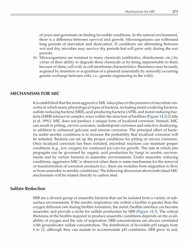
P1: FPVCE003-14 CE003-Peabody November 6, 2000 10:19 Char Count= 0
Mechanisms for MIC 275
of years and germinate on finding favorable conditions. In the natural environment,there is a difference between survival and growth. Microorganisms can withstandlong periods of starvation and desiccation. If conditions are alternating betweenwet and dry, microbes may survive dry periods but will grow only during the wetperiods.
11. Microorganisms are resistant to many chemicals (antibiotics, disinfectants, etc.) byvirtue of their ability to degrade these chemicals or by being impenetrable to thembecause of slime, cell wall, or cell membrane characteristics. Resistance may be easilyacquired by mutation or acquisition of a plasmid (essentially by naturally occurringgenetic exchange between cells, i.e., genetic engineering in the wild).
MECHANISMS FOR MIC
It is established that the most aggressive MIC takes place in the presence of microbial con-sortia in which many physiological types of bacteria, including metal-oxidizing bacteria,sulfate-reducing bacteria (SRB), acid-producing bacteria (APB), and metal-reducing bac-teria (MRB) interact in complex ways within the structure of biofilms (Figure 14.2) (Littleet al. 1991). MIC does not produce a unique form of localized corrosion. Instead, MICcan result in pitting, crevice corrosion, underdeposit corrosion and selective dealloying,in addition to enhanced galvanic and erosion corrosion. The principal effect of bacte-ria under aerobic conditions is to increase the probability that localized corrosion willbe initiated. Bacteria can set up the proper conditions for pitting or crevice corrosion.Once localized corrosion has been initiated, microbial reactions can maintain properconditions (e.g., low oxygen) for continued pit/crevice growth. The rate at which pitspropagate can be governed by organic acid production by fungi in aerobic environ-ments and by certain bacteria in anaerobic environments. Under anaerobic reducingconditions, aggressive MIC is observed when there is some mechanism for the removalor transformation of corrosion products (i.e., there are switches from stagnation to flowor from anaerobic to aerobic conditions). The following discussion about individual MICmechanisms will be related directly to carbon steel.
Sulfate Reduction
SRB are a diverse group of anaerobic bacteria that can be isolated from a variety of sub-surface environments. If the aerobic respiration rate within a biofilm is greater than theoxygen diffusion rate during biofilm formation, the metal/biofilm interface can becomeanaerobic and provide a niche for sulfide production by SRB (Figure 14.3). The criticalthickness of the biofilm required to produce anaerobic conditions depends on the avail-ability of oxygen and the rate of respiration. SRB concentrations are always correlatedwith groundwater sulfate concentration. The distribution of favorable pH ranges from6 to 12, although they can mutate to accommodate pH conditions. SRB grow in soil,
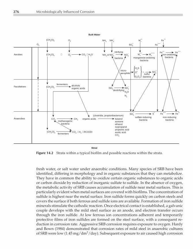
P1: FPVCE003-14 CE003-Peabody November 6, 2000 10:19 Char Count= 0
276 Microbiologically Influenced Corrosion
=
Bulk Water
Metal
Aerobes
Facultatives
Anaerobes CO2
(CH2O)n CO2 + H2 + RCOOH
CO2 + H2O(CH2O)n +
(CH2O)n
(CH2O)n
O2
CH4
SO4
=S
=Fe
+++
Fe++
Fe++
Fe+++
SO4
=
Mn
++Mn
++++ Fe+++
Mn
++
SO4
=
NH3 or NO2
−NO3
−
NO3
−NO2
−
N2O
N2
H2S
So
S2O3
NH3
O2
O2 NH3
−
Fe++
methanogenicbacteria
fermenters
organic acids(clostridia, propionibacterium)
butanolacetoneethanolisopropanolpropionic acidacetic acidCO2
sulfate-reducingbacteria
iron-reducingbacteria
fermenters alcoholsorganic acids
denitrifying
micro-aerophilic sulfur
bacteria
manganese-oxidizingbacteria
iron-oxidizingbacteria
nitrifying
bacteria
Figure 14.2 Strata within a typical biofilm and possible reactions within the strata.
fresh water, or salt water under anaerobic conditions. Many species of SRB have beenidentified, differing in morphology and in organic substances that they can metabolize.They have in common the ability to oxidize certain organic substances to organic acidsor carbon dioxide by reduction of inorganic sulfate to sulfide. In the absence of oxygen,the metabolic activity of SRB causes accumulation of sulfide near metal surfaces. This isparticularly evident when metal surfaces are covered with biofilms. The concentration ofsulfide is highest near the metal surface. Iron sulfide forms quickly on carbon steels andcovers the surface if both ferrous and sulfide ions are available. Formation of iron sulfideminerals stimulate the cathodic reaction. Once electrical contact is established, a galvaniccouple develops with the mild steel surface as an anode, and electron transfer occursthrough the iron sulfide. At low ferrous ion concentrations adherent and temporarilyprotective films of iron sulfides are formed on the steel surface, with a consequent re-duction in corrosion rate. Aggressive SRB corrosion requires exposure to oxygen. Hardyand Bown (1984) demonstrated that corrosion rates of mild steel in anaerobic culturesof SRB were low (1.45 mg/dm2/day). Subsequent exposure to air caused high corrosion

P1: FPVCE003-14 CE003-Peabody November 6, 2000 10:19 Char Count= 0
Mechanisms for MIC 277
Biofilm surface
4
4
5
5
6
6
pH
Metal surface
1 2 3
Dissolved oxygen concentration (mg/L)
Log of total sulfide concentration (mol/L)
−9 −8 −7 −6 −5 −4 −3 −2 −1
Dissolved oxygen
Sulfide
pH
DIS
TAN
CE
(m
icro
met
ers)
3500
3000
2500
2000
1500
1000
500
0
−500−1 0
Figure 14.3 Concentration profiles of sulfide, oxygen, and pH in a biofilm on carbon steel.(From Biofouling, 1993. Reprinted with permission from Overseas Publishers Association(OPA) and Gordon and Breach Publishers.)
rates (129 mg/dm2/day). Accordingly, structures that are exposed under fully deaer-ated conditions generally experience low corrosion rates despite the presence of highconcentrations of SRB.
Acid Production
Organic acids can be produced by both bacteria and fungi. Most of the final products ofMIC community metabolism are short-chained fatty acids like acetic acid that are veryaggressive in the attack of carbon steel, and become especially aggressive when concen-trated under a colony or other deposit. This type of attack is accelerated by the additionof chloride. The resulting chloride-rich corrosion products have a greater volume and areless stable, often flaking from the surface. Other bacterial species can produce aggressiveinorganic acids, such as H2SO4. Microorganisms in the soil may generate high concen-trations of carbon dioxide. The carbon dioxide dissolves in the groundwater, producingcarbonic acid. Carbonic acid solution is very corrosive to pipeline steels and can lead togeneral attack, pitting attack, and stress corrosion cracking.

P1: FPVCE003-14 CE003-Peabody November 6, 2000 10:19 Char Count= 0
278 Microbiologically Influenced Corrosion
Metal Deposition
Microorganisms can also affect corrosion by creating differential aeration cells on thesurface of the metal and fixing the location of anodic sites beneath colonies of microor-ganisms. The organisms most often cited as causing differential aeration cells are thoseorganisms capable of depositing iron and manganese oxides.
Manganese oxidation and deposition is coupled to cell growth and metabolism of or-ganic carbon. The reduced form of manganese (Mn+2) is soluble and the oxidized forms(Mn2O3, MnOOH, Mn3O4, MnO2) are insoluble. As a result of microbial action, man-ganese oxide deposits are formed on buried or submerged materials including metal,stone, glass, and plastic, and can occur in natural waters that have manganese con-centrations as low as 10 to 20 ppb (Figure 14.4). For mild steel corrosion under anodiccontrol, manganese oxides can elevate corrosion current. The current may be signifi-cant for biomineralized oxides that provide large mineral surface areas. Given sufficient
Figure 14.4 Black manganese dioxide deposits oncarbon steel caused by metal-depositing bacteria.
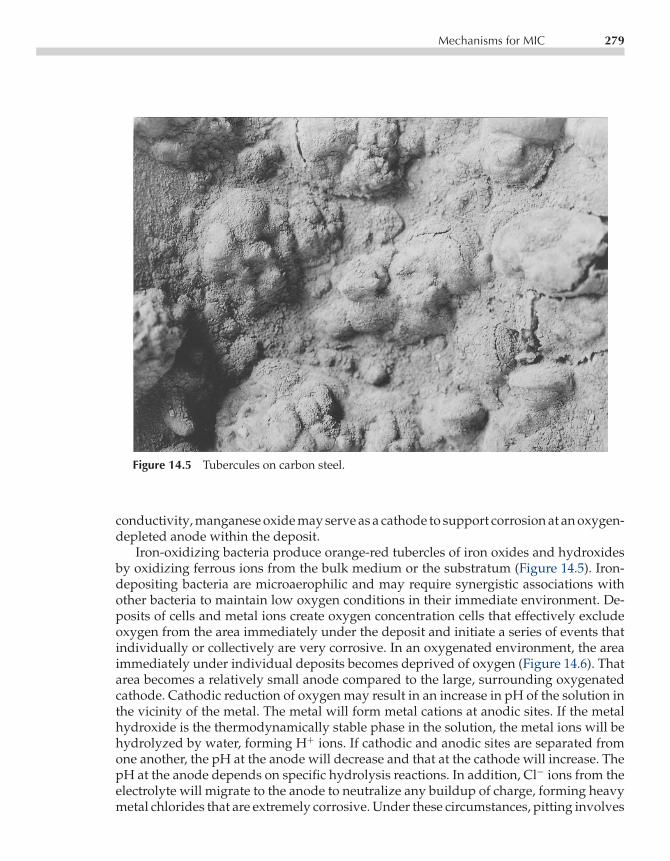
P1: FPVCE003-14 CE003-Peabody November 6, 2000 10:19 Char Count= 0
Mechanisms for MIC 279
Figure 14.5 Tubercules on carbon steel.
conductivity, manganese oxide may serve as a cathode to support corrosion at an oxygen-depleted anode within the deposit.
Iron-oxidizing bacteria produce orange-red tubercles of iron oxides and hydroxidesby oxidizing ferrous ions from the bulk medium or the substratum (Figure 14.5). Iron-depositing bacteria are microaerophilic and may require synergistic associations withother bacteria to maintain low oxygen conditions in their immediate environment. De-posits of cells and metal ions create oxygen concentration cells that effectively excludeoxygen from the area immediately under the deposit and initiate a series of events thatindividually or collectively are very corrosive. In an oxygenated environment, the areaimmediately under individual deposits becomes deprived of oxygen (Figure 14.6). Thatarea becomes a relatively small anode compared to the large, surrounding oxygenatedcathode. Cathodic reduction of oxygen may result in an increase in pH of the solution inthe vicinity of the metal. The metal will form metal cations at anodic sites. If the metalhydroxide is the thermodynamically stable phase in the solution, the metal ions will behydrolyzed by water, forming H+ ions. If cathodic and anodic sites are separated fromone another, the pH at the anode will decrease and that at the cathode will increase. ThepH at the anode depends on specific hydrolysis reactions. In addition, Cl− ions from theelectrolyte will migrate to the anode to neutralize any buildup of charge, forming heavymetal chlorides that are extremely corrosive. Under these circumstances, pitting involves

P1: FPVCE003-14 CE003-Peabody November 6, 2000 10:19 Char Count= 0
280 Microbiologically Influenced Corrosion
Oxygen-ContainingWater
O2
Cl− Cl−
Aerobic Bacteria
Metal-Depositing Bacteria
O2 + 2H2O + 4e− → 4OH−
Oxide Layer
Anode
M → M2+ + 2e−
M2+ + 2H2O → M (OH)2 + 2H+
Figure 14.6 Possible reactions under tubercles created by metal-deposit-ing bacteria.
the conventional features of differential aeration, a large cathode-to-anode surface area,and the development of acidity and metallic chlorides. Pit initiation depends on mineraldeposition by bacteria. Pit propagation is dependent not on activities of the organisms,but on metallurgy.
Metal Reduction
Dissimilatory iron and/or manganese reduction occurs in several microorganisms, in-cluding anaerobic and facultative aerobic bacteria. Inhibitor and competition experi-ments suggest that Fe+3 and Mn+4 are efficient electron acceptors that are similar tonitrate in redox ability and are capable of out-competing electron acceptors of lowerpotential, such as sulfate or carbon dioxide (Meyers 1988). MRB in direct contact withsolid iron (Fe+3) and manganese (Mn+4) oxides produce soluble ions (Fe+2 and Mn+2).The result is dissolution of surface oxides and localized corrosion that was described byObuekwe et al. (1981) as anodic depolarization.
MIC ON PIPELINES
Environment
The potential for MIC on buried pipelines is controlled by availability of nutrients, water,and electron acceptors. Peabody (1967) reported data from Harris (1960) indicating that

P1: FPVCE003-14 CE003-Peabody November 6, 2000 10:19 Char Count= 0
MIC on Pipelines 281
soil moisture content and bacterial cell counts were greater in backfill material than inundisturbed earth adjacent to a pipeline. Trench backfill is not as consolidated and al-lows greater penetration of moisture and increased oxygen diffusion. Anaerobic bacteriathrive in waterlogged, dense soil. Alternating moisture and oxygen concentrations willinfluence the growth of bacterial populations. Despite the numerous mechanisms thatone would predict for MIC of buried pipelines, most failures have been attributed tothe presence and activities of SRB and APB. In general, sandy soils favor APB; high claysoils support populations of both kinds of organisms. To protect against all forms ofexternal corrosion and cracking, several coating materials are used including asphalts,polyolefin tapes, and fusion-bonded epoxies (FBE). Line pipe is further protected byan impressed current or cathodic protection (CP). MIC can occur in the presence of thesepreventative measures.
Coatings
Because of differing environmental conditions (e.g., soil moisture, microflora, nutrients)in both field surveys and laboratory experiments, it is extremely difficult to interpretcomparisons of coating performance. Soil stress or tenting along irregularities on thepipe surface, especially at long seam or girth welds, can create gaps between the tapeand the pipe surface that fill with ground water and introduce microorganisms that createcorrosion cells under the disbonded coating. Tenting is most prevalent in wet high claysoils, on unstable, geologically active slopes and downstream compressor stations. Highservice temperatures also promote disbonding. Not all coating materials are affected bysoil bacteria under all conditions. Coatings derived from both coal (tars) and petroleum(asphalts) pass some exposure tests and fail others. Materials which by themselves showresistance to attack by microorganisms fail when combined or reinforced with othermaterials.
Peabody (1967) reported that coal tars, coal tar epoxies, and coal tar enamels wereimmune to disbonding because of activities of microorganisms. Early coatings based onasphalt were subject to oxidation and loss of low-molecular weight components throughbiodegradation and biodeterioration, resulting in a permeable, embrittled coatings (Jacket al. 1996). Pendrys (1989) demonstrated that with time asphalt could be degradedby microorganisms selected from soil. Harris (1960) demonstrated that bacteria foundcommonly in pipeline soils can degrade asphalt, tape adhesives, kraft paper (expendableonce line is in place), and binders and fillers used in felt pipeline wrappers. The nextgeneration coatings were based on polyolefin tapes made of polyvinyl chloride (PVC)or polyethylene (PE). The PVC tape was unstable in service. Plasticizers constitute upto 50% of a PVC product and can be effectively lost through biodeterioration and waterdissolution. Tape coatings rely on adhesives to attach the polyolefin layer to the primedsteel surface.
Jack et al. (1996) demonstrated that certain coatings disbonded more readily afterbeing exposed to soils containing SRB and APB. PE coating damage proceeded lin-early with time. PE tape coatings supported higher bacterial counts than extruded PE

P1: FPVCE003-14 CE003-Peabody November 6, 2000 10:19 Char Count= 0
282 Microbiologically Influenced Corrosion
or fusion-bonded epoxy (FBE), presumably because of the presence of biodegradableadhesive/primer components in the paint system. Susceptibility to disbonding increasedin the order: FBE, extruded PE, and PE tape. Two types of coating damage were reported:damage due to water leaching and permeation, which affect intact coatings and coatingaround holidays. FBE coatings were damaged with increased susceptibility to cathodicdisbondment at existing holidays.
The most prevalent mechanism for the observed corrosion in a study reported byJack et al. (1996) was formation of a galvanic couple between microbiologically producediron sulfides and steel. The couple is normally short-lived because the iron sulfide matrixbecomes saturated with electrons derived from the corrosion process. In the presence ofSRB, however, the corrosion process is perpetuated because SRB can remove electrons inthe corrosion process from the iron sulfide surface. This process may involve formationof cathodic hydrogen on the iron sulfide or direct transfer of electrons from the ironsulfide matrix to redox proteins in the bacterial cell wall. Corrosion rates associated withthis mechanism were proportional to the amount of iron sulfide in the corrosion cell.
Cathodic Protection
Cathodically polarized surfaces attract microorganisms, including SRB, so that, if theCP is interrupted MIC can occur at a higher rate than if CP were not previously present(Sanders and Maxwell 1983). MIC has at least three effects on CP of pipelines. First, whereMIC activity is present, the potential level required to mitigate corrosion is moved to morenegative values. Pope and Morris (Pope 1995) found that pipeline failures were often incontact with wet clays with little scaling potential, creating the situation in which thedemand for CP continued at a high level over long periods of time and in which CP maynot be distributed equally over the surface of holidays and surrounding disbondments.Microorganisms colonize and initiate corrosion at such sites. Research by Barlo andBerry (1984) showed that a potential of at least −950 mV (copper/copper sulfate) isrequired to mitigate MIC, as opposed to the standard NACE International criterion of−850 mV. Second, MIC can increase the kinetics of the corrosion reactions, increasing theCP current necessary to achieve a given level of polarization. Third, microorganisms canattack pipeline coatings, increasing exposed metal surface area and further increasingthe CP current required to achieve a given level of polarization. Water intrusion at breaksin the coating may block CP.
Detection
Because microorganisms are ubiquitous, the presence of bacteria or other microorgan-isms does not necessarily indicate a causal relationship with the corrosion. Microorgan-isms can always be cultured from natural environments but are not always the causefor corrosion found in their presence. Other factors must be considered in determininga cause and effect relationship. Areas of high SRB activity are generally very negative

P1: FPVCE003-14 CE003-Peabody November 6, 2000 10:19 Char Count= 0
References 283
in potential and can be located by means of a native potential survey if the followingconditions are met: (1) area of MIC activity must be large, (2) CP system must be off,and (3) coating cannot shield the metal surface. Once a suspected area of MIC has beenlocated, the presence of bacteria can be confirmed by means of bell hole inspections inconjunction with the application of the analytical techniques described in NACE TPCPublication 3 in (NACE 1990), including culture methods and antibody analyses. A dropof dilute hydrochloric acid placed on corrosion product deposits will produce the odor ofrotten eggs when sulfides are present. Detection of SRB or other bacteria in deposits as-sociated with accelerated corrosion does not conclusively establish a casual relationshipbetween the bacteria and the observed corrosion (Little 1996).
SUMMARY
Backfill around pipelines provides an environment that supports microbial growth morethan what is expected for undisturbed soil. Nutrients associated with coatings andcathodic polarization encourage microbial settlement on pipeline surfaces. Extensiveanalyses of field samples indicate that MIC of external surfaces of buried pipeline andother underground structures is most often associated with SRB and APB and disbondedcoatings.
ACKNOWLEDGMENTS
Work was performed by the Office of Naval Research, Program Element 0601153Nand Defense Research Sciences Program, NRL Contribution Number NRL/BA/7333-97-0056.
REFERENCES
T.J. Barlo, W.E. Berry. Materials Performance 23, 9, 1984, p. 9.J.A. Hardy, J.L. Bown. Corrosion 40, 1984, p. 650.J.O. Harris. Corrosion 16, 1960, p. 441.T.R. Jack, G. Van Boven, M. Wilmott, R. Worthingham. Materials Performance 35, 3, 1996, p. 39.T.R. Jack, M.J. Wilmott, R.L. Sutherby, R.G. Worthingham. Materials Performance 35, 3, 1996, p. 18.W. Lee, Z. Lewandowski, M. Morrison, W.G. Characklis, R. Avci, P. Nielsen. Biofouling 7, 1993,p. 217.B.J. Little, R. Ray, P. Wagner, Z. Lewandowski, W.C. Lee, W.C. Characklis. Biofouling 3, 1991, p. 43.B.J. Little, P.A. Wagner, K.R. Hart, R.I. Ray. Spatial Relationships Between Bacteria and LocalizedCorrosion. Corrosion/96, paper no. 278, Houston, TX: NACE International, 1996.

P1: FPVCE003-14 CE003-Peabody November 6, 2000 10:19 Char Count= 0
284 Microbiologically Influenced Corrosion
Microbiologically Influenced Corrosion and Biofouling in Oilfield Equipment. TPC Publication 3,NACE International, Revised September 1990.C. Myers, K.H. Nealson, Science 240, 1988, p. 1319.C.O. Obuekwe, D.W.S. Westlake, J.A. Plambeck, F.D. Cook. Corrosion 37, 8, 1981, p. 461.A.W. Peabody. Control of Pipeline Corrosion, Houston, TX: NACE International, 1967, p. 173.J.P. Pendrys. Appl. Environ. Microbiol. 55, 6, 1989, p. 1357.D. Pope. A Study of Microbiologically Influenced Corrosion in Nuclear Power Plants and a PracticalGuide for Countermeasures. Electric Power Research Institute Report NP-4582, May 1986. PaloAlto, CA.D.H. Pope, E.A. Morris III. Materials Performance 34, 5, 1995, p. 23.P.F. Sanders, S. Maxwell. Microfouling, Macrofouling, and Corrosion of Metal Test Specimens inSeawater. In: Microbial Corrosion, Teddington, UK: Metals Society, 1983, p. 74.

P1: FKICE003-15 CE003-Peabody October 31, 2000 16:27 Char Count= 0
Chapter15Economics
Ronald L. Bianchetti
Good economics principles should be used in all pipeline corrosion work. To assuresuccessful implementation of a corrosion control program, the corrosion engineer mustbe able to express the benefits in terms that management can understand, and that isthrough economic analysis.
Over the years the cost of implementing a corrosion control system has proven to beextremely beneficial in the reduction of leaks and extension of the useful life of pipelines.Whether by using coating alone or coating with cathodic protection (CP), pipeline ownershave obtained very good results when sound corrosion engineering is implemented.The additive cost for corrosion control typically represents a very small percentage ofinitial pipeline construction costs. With this in mind corrosion control systems shouldbe implemented as a standard operating procedure for all buried pipeline systems toenhance the life of the asset. Some examples of economic considerations are discussedbelow.
ECONOMIC COMPARISONS
The prime objective in pipeline corrosion control work is to maintain a corrosion-free sys-tem at the lowest annual cost. The total annual cost is frequently used as a simple meansof comparing the relative cost of alternate means of applying protection to sections of apipeline system. This cost figure includes the annual cost of the capital invested plus theannual cost of operating and maintaining the system. To make annual cost comparisonsthat are valid, the pipeline corrosion engineer must know the various component costitems with reasonable accuracy.
Existing Pipelines
When CP is planned for existing pipelines that have an established leak history, it ispossible to forecast the number and cost of probable leaks that may occur if CP were not
285
P1: FKICE003-15 CE003-Peabody October 31, 2000 16:27 Char Count= 0
286 Economics
applied to the total cost of CP. These costs are evaluated for a period of time, typically20 to 50 yr.
New Pipelines
Where CP is installed at the time a pipeline is built, there will be no leak history onwhich to base the type of comparison previously mentioned. However, established leakhistories of other pipelines in the same area can be a valuable guide to indicate theprobable savings to be gained by installing CP.
Comparisons can be made for planned pipelines where the choice is between in-stalling CP initially, or installing the pipeline without CP but providing a corrosionallowance such as an extra 1
16 -inch pipe-wall thickness beyond that needed for designoperating conditions. The comparison may be based on the annual cost of the CP onthe thinner wall pipe versus the annual cost of the investment for the additional steel inthe pipe having the corrosion allowance. The probability should be recognized that thepipe having the extra wall thickness ultimately would reach the point where it, too, willrequire CP.
Cost of Money
The cost of money invested for CP installations or other corrosion control measuresis usually developed by the company financial specialists. The money used for suchinvestments can cost more than the simple interest rate. Included also in the cost aresuch items as taxes and depreciation that increase the real cost to the company of themoney invested.
There can be a difference between the cost of money used for installations made undercapital expenditure funding versus those made using maintenance funds. The corro-sion engineer should determine the difference, because corrosion control installationsmay be capitalized in some instances (for new pipeline construction) and considered asmaintenance costs in others.
Establishing Initial Cathodic Protection System Cost Estimates
When evaluating economic comparisons, estimates of the total installed cost of alternatesystems (galvanic anodes versus impressed current) should be considered. Validity ofthe economic comparisons will depend largely on the accuracy of the cost figures usedin compiling the estimates.
An estimate for the installed cost of a CP system includes such items as the following:
• Engineering time and associated expenses for field-testing, design, and preparation ofplans and specifications.

P1: FKICE003-15 CE003-Peabody October 31, 2000 16:27 Char Count= 0
Economic Comparisons 287
• Cost of materials plus the overhead expense to cover purchasing and storage costs. Theoverhead factor or other means of determining these costs should be decided for theparticular company.
• Cost of right-of-way acquisition, if involved. This includes cost of right-of-way ease-ments, time and expenses for right-of-way procurement personnel, and crop damagewhere applicable.
• Unit construction costs for the various components of the systems to be installed. Thecorrosion engineer will need to establish a working file on costs. If installations are tobe made by company crews, review the proposed work with appropriate companypersonnel for their estimates of all charges that would be made against a work orderfor the installation. If possible, the estimate should be broken down into unit costs(such as trenching cost per foot, cost per anode for installation, etc.).
If installations are to be made by a CP construction contractor, that person may bewilling to provide scoping estimates. The new corrosion engineer may be able to obtainestimating figures from experienced corrosion engineers with neighboring pipeline sys-tems who have direct knowledge of applicable contract construction costs in the samegeneral area. Where corrosion-engineering consultants are used, they can assist the newcorrosion engineer by providing established reliable figures for cost estimating purposes.
• Inspection time and associated expenses on the part of the corrosion engineer duringthe actual construction phase.
• Completed system check out and associated expenses of the corrosion engineer to verifyadequate protection is being achieved. Performing CP current output adjustments asnecessary and conducting cooperative interference tests as may be necessary.
Establishing On-Going Operating Cost Estimates
Estimates for the annual operating costs for a pipeline CP installation should includesuch items as the following:
• Power costs where rectifiers are to be used as a current source. Applicable power com-pany rates for the appropriate class of service should be known. If minimum monthlyrates apply, they should be taken into account. This usually applies to small rectifierinstallations. In some instances, however, if the electric company has to build a longpower line extension to serve the rectifier, it may establish a fairly substantial mini-mum monthly billing over a period of years to recover the cost of the line extension.Where other current sources using an outside source of energy are used (thermo-electric generators for example), the cost of fuel required to operate the device mustbe determined.
• Maintenance and system checkout costs include time and associated expenses for rou-tine operational checks (particularly applicable for systems using rectifiers or otherDC power sources subject to relatively frequent inspection); time and expense for

P1: FKICE003-15 CE003-Peabody October 31, 2000 16:27 Char Count= 0
288 Economics
periodic corrosion surveys along that section of the system protected by the proposedinstallation; and an estimate for time, expenses, and materials for corrective repairwork.
COST COMPARISON EXAMPLES
To illustrate cost comparisons of different CP systems the following examples are pre-sented to assist the corrosion engineer.
Comparing Alternative Cathodic Protection Systems
Assume a new 50-mile well-coated pipeline to be cathodically protected. Initial corro-sion survey tests show that protection can be obtained with 2 A from a single rectifierinstallation near the center of the line or with 1.5 A from three magnesium anode in-stallations distributed along the line. Less current is required for the magnesium anodesystem because of reduced attenuation resulting from distributed installations.
Impressed Current System
On the basis of the corrosion survey, it has been determined that the rectifier can be in-stalled at a location where soil conditions are such that a ground bed with three verticalanodes at 20-ft spacing can be placed 300 ft from the pipeline. This system will providethe required 2 A at 5 V. Electric service is available at the installation site and the appli-cable power rate is 3.5 cents per kwh for the first 250 kwh per month with a minimummonthly bill of $2.50. (Power costs vary from area to area. Actual local rates should bedetermined.) Right-of-way acquisition will be necessary.
Galvanic Anode System
At the three magnesium anode installations, assume that the initial corrosion survey datahave shown that installation sites are available. Soil conditions at the three installationswill produce 0.5 A of protection current (with the pipe at protected potentials) using five20-lb packaged magnesium anodes at 15-ft spacing along the edge of the right-of-way15 ft from the pipe. No right-of-way costs will be incurred.
To determine which type of installation will be the more economical, the pertinentcosts can be compared as shown in Table 15.1. It is assumed that the necessary stepshave been taken to obtain reliable estimating figures and that this final comparisonsummarizes and compares the cost data obtained.

P1: FKICE003-15 CE003-Peabody October 31, 2000 16:27 Char Count= 0
Cost Comparison Examples 289
Table 15.1 Economic Comparision Between Alternative CP Systems
Total forRectifier 3 Magnesium
Description Installation Anode Installations
A-INSTALLATION COSTS
1. Time(1) and expense for fieldtests, design, plans andspecifications $1065 $968
2. Cost of materials including10 percent for overhead $2400 $1950
3. Right-of-way acquisition costs $1000 –4. Contract installation cost $4700 $45005. Time and expense for construction
inspection $1500 $15006. Time and expense for system
check-out(2) $2500 $1500
TOTAL INSTALLATION COST $13,165 $10,418
ANNUAL COST OF MONEY $1184 $937(Based on an assumed 4 percentfor 15 year system life)
B-OPERATING COSTS
1. Power cost(3) $100 –2. Routine operational checks(4) $100 –3. Periodic corrosion survey $700 $5004. Time, expenses and materials for
corrective repairs(5) $50 $50
TOTAL ANNUAL OPERATING COST $950 $550
C-ECONOMIC COMPARISON
ANNUAL COST OF MONEY (A) $1184 $937TOTAL ANNUAL OPERATING COST (B) $950 $550
TOTAL ANNUAL COST $2134 $1487
(1)Engineering time charges for operating company personnel include, normally, an overheadcharge. This can be determined for the particular company involved.(2)Additional check-out time for rectifier installations to allow for additional interference checks.(3)Power consumption is less than minimum billing which applies in this instance.(4)Based on rect. readings every month.(5)Estimated annual repair cost.

P1: FKICE003-15 CE003-Peabody October 31, 2000 16:27 Char Count= 0
290 Economics
This comparison indicates that the three magnesium anode installations will have alower annual cost than the single rectifier and would, therefore, be more economical.Although this is usually the case for lower current outputs (typically less than 2A) usedin this example, a similar comparison should be made using the specific factors thatapply to the pipeline corrosion engineer’s own system.
On the other hand if the amount of current required was higher, an impressed cur-rent system tends to become more economical than galvanic anode installations. Thisis because the additional investment for added rectifier output (in terms of dollars perampere of capacity) does not increase as rapidly as that for galvanic anode installations.
Comparing Leak Cost and Cathodic Protection Cost
When a section of pipeline system starts to develop leaks, experience has shown thatfurther leaks will develop at a continuously increasing rate. If the accumulated numberof leaks repaired is plotted on semilog paper against pipeline age in years, a straightline is the usual result where accurate leak records are available (Figure 15.1). In this
2 4 6 8 10 12 14 16 18 20 22 24
YEARS AFTER PIPELINE INSTALLATION
CU
MU
LAT
IVE
NU
MB
ER
OF
LE
AK
S
40
30
20
910
2
1
3
4
5
678
50
60708090
100
CATHODICPROTECTIONAPPLIED
PROJECTEDLEAKS WITHOUTPROTECTION
Figure 15.1 Cumulative number of leaks without CP.

P1: FKICE003-15 CE003-Peabody October 31, 2000 16:27 Char Count= 0
Cost Comparison Examples 291
instance, the first leak did not develop until the line was 4-yr old and a total of only sevenleaks had developed by the time the pipeline was 12-yr old. A definite trend has beenestablished, which shows that in the next 10-yr there will be approximately 70 new leaks,if corrosion is not controlled. The figure also shows that the number of leaks developingeach year is increasing at such a rate that the pipeline may become inoperable if the trendis not stopped.
The application of CP as shown in Figure 15.1 can mitigate development of new leaks.The cost of operating a CP system(s) versus the cost of leaks over a period of time canthen be economically evaluated. In the case illustrated (Figure 15.1), application of CPat the end of the 12th year would eliminate approximately 70 new leaks over the next10-yr period. Thus a dollar figure can be developed to represent the cost savings for theanticipated leaks.
To determine the cost of leaks several items should be considered.
• The average cost of a leak repair on the pipeline under study. This should includelabor, overhead, materials, transportation costs, and other attendant expenses.
• An average cost for property damages associated with a simple corrosion leak repair.This can vary with the fluid in the pipeline. Such damages tend to be substantiallyhigher, if a pipeline is carrying petroleum or petroleum products versus natural gas.
• The value of product lost from an average corrosion leak. This will depend on theproduct, the pipeline pressure, the average size of the leak, and the average length oftime that/product escapes before the leak repair is accomplished.
• Miscellaneous factors, such as insurance, good will, and other costs.
The total average cost of each leak, will be the sum of the above items plus any associatedcosts that may be involved for the particular pipeline system under consideration.
Now assume that a coated pipeline having the leak record represented by Figure 15.1is surveyed during its 12th yr and that design calculations indicate that CP can be appliedusing a rectifier system. Further assume that the annual cost of the investment for CPplus annual operating costs will be $6,000 per year and it has been established that theaverage total cost of each leak repaired is $1500. Using these figures, if CP is applied atthe end of the 12th yr, comparative costs for the following 10-yr period are as follows:
• Cathodic protection costs: 10× $6000 = $60,000• Savings in leak repair costs: 70× $1500 = $105,000
This example indicates that, over the 10-yr period, there will be a net savings of $45,000with CP installed, if all leaks are avoided.
Greater savings can be shown by projecting the comparison over a longer periodbecause although CP annual costs remain reasonably uniform, the number of projectedleaks over that longer period increases very rapidly. (Note, from Figure 15.1, that therewould be approximately 20 new leaks in the 23rd yr alone.)

P1: FKICE003-15 CE003-Peabody October 31, 2000 16:27 Char Count= 0
292 Economics
Now look at the comparison that would apply for the same pipeline if CP had beeninstalled when the line was initially constructed. First, the annual cost of CP would beless because the new coating would be better initially. Second, the coating should besubstantially better after 12-yr. Third, the full 22-yr of pipeline life is considered in theannual cost analysis, so the annual cost allocation for CP would be $4,000. The totalnumber of leak repairs saved, per Figure 15.1, would be 80 over the 22-yr period. Thecomparison now is as follows:
• Cathodic protection costs: 22× $4,000 = $88,000• Savings in leak repair costs: 80× $1500 = $120,000
Assuming that annual costs for CP have been estimated accurately, there is still a signifi-cant saving of $32,000 with CP.
The previous comparison may be used as an argument in favor of deferring theapplication of CP until leaks have started to develop. This would only be valid if therewas a guarantee that all leaks would be simple leaks, as assumed in the cost comparisons,with no risk of exceptional hazard. For pipelines carrying a hazardous product (such asnatural gas or petroleum products), there is always the possibility of fire, explosion orloss of life if the leak should develop in the wrong place. Since these are possibilities only(although very real possibilities), a dollar figure cannot be attached readily to the directcost that might be involved nor to intangible factors such as impaired public good will.Just one serious incident, if it should occur, can more than offset any apparent savingwhich could be gained by deferring application of CP until leaks start to develop.
Comparing Cathodic Protection with Pipe Corrosion Allowance
A corrosion allowance for example, an additional 116 of an inch of pipe wall thickness
(above that needed for pipeline operating considerations) may be considered in lieu ofapplying CP. This practice is not recommended for underground pipelines, because itdoes not provide a permanent means of corrosion control but only defers the time whena leak will occur.
Ground Bed Cable Sizing and Anode Spacing
Economic considerations apply to various phases of CP system design. Sizing groundbed cables and determining the economic spacing for impressed current or galvanicanodes are particularly important instances.
Ground Bed Cable Size
Basically, ground bed cable can be increased in size as long as each incremental increasewill show a dollar savings in terms of reduced annual power losses in the cable resistance

P1: FKICE003-15 CE003-Peabody October 31, 2000 16:27 Char Count= 0
Cost Comparison Examples 293
compared with the annual cost of the additional investment for the larger cable size. Forrectifier installations, AC power losses (which determine the cost) are the DC powerlosses in the cable divided by the rectifier efficiency expressed as a decimal.
As was discussed in Chapter 7, the effective resistance of the ground bed cable maybe taken as that of the full length of cable between pipeline and first anode plus that ofone-half the length of cable along the line of anodes. Power costs at rectifier installationsare determined from the power company rate schedule. For small rectifier installations,which do not use enough power to exceed the minimum monthly billing, nothing isgained by using a larger cable size than is necessary for adequate mechanical strength.No. 8 AWG header cable (the same size as the usual anode pigtail cable) may be con-sidered the smallest practical size, although some operators may elect to use no smallerthan No. 4 AWG cable for header cable construction.
Power costs at galvanic anode installations vary with the size and type of installa-tion but can be reduced to a cost per kilowatt-hour (kWh). This is performed by firstdetermining the kWh lifetime output of the installation by the expression.
kWh = driving voltage× amps output× 8.76× installation life in years.
The cost per kWh is then the installation cost in dollars divided by the expected totallifetime power output in kWh.
Although the cost per kWh for a galvanic anode installation usually will be severaldollars compared with only a few cents at a rectifier installation (where the monthlyminimum bill is exceeded), there may be no economic advantage in using cable largerthan needed for strength. This is because the square of the current output of a smallgalvanic anode installation may be very small compared with that of a rectifier instal-lation (and in addition there is much less cable in the usual galvanic anode installationthan in the typical rectifier ground bed).
Anode Spacing
Based on the information on ground bed design discussed in Chapter 7, it is recognizedthat for soil of uniform resistivity, two boundary conditions for anode spacing exist.These are the following:
• The parallel resistance of two vertical ground bed anodes placed side by side will beonly slightly less than the resistance of one anode alone.
• The parallel resistance of two vertical ground bed anodes placed electrically far apartwill be approximately one-half the resistance of one anode alone.
Both of these boundary conditions are not economical. The most economical anodespacing is somewhere between these two conditions.
Using proper materials, right-of-way procurement, installation, and power costs,the pipeline corrosion engineer can make an economic analysis to determine the most

P1: FKICE003-15 CE003-Peabody October 31, 2000 16:27 Char Count= 0
294 Economics
0 5 10 15 20 25 30
0
ANODE SPACING IN FEET
AN
NU
AL
CO
ST
OF
TO
TAL
INV
ES
TM
EN
TF
OR
GR
OU
ND
BE
D C
ON
ST
RU
CT
ION
Figure 15.2 Typical plot for economical anode spacing.
favorable spacing for installations. This may be done by calculating, for a typical groundbed resistance in typical soil resistivity, the annual cost of the total investment requiredfor constructing a ground bed at several different anode spacing points. The annual costof power losses in the cable should be added to the annual cost of the investment. Byplotting a total annual cost versus the cost of anode spacing, a curve will be obtainedwhich may appear somewhat as indicated in Figure 15.2. Although the results may varywith costs applicable to a particular system, economical anode spacing of 20 to 25 ft istypical for rectifier ground bed construction.
ECONOMICS OF GOOD MAINTENANCE
The most obvious economic contributor is good maintenance. This means maintainingall CP installations and other corrosion control facilities in optimum operating conditionand making sure that full protection is being given the system for the maximum practica-ble percentage of the time. This is a necessity for proper system performance. Withoutproper maintenance and system performance the initial investment is not optimized,and the cost of the corrosion control investment represents a wasted expenditure. Thisis not an acceptable practice and is highly discouraged.
Maintenance economics applies to equipment use in CP installations. At rectifierinstallations particularly, as discussed in Chapter 8, economies can be gained by replacingrectifying elements (stacks) in older units with new more efficient elements when theannual saving in power cost is greater than the annual cost of the investment for the

P1: FKICE003-15 CE003-Peabody October 31, 2000 16:27 Char Count= 0
Coating Economics 295
new stacks. In extreme cases involving large single-phase rectifiers, changing the single-phase unit for a more efficient three-phase rectifier may prove economical on the annualcost basis if three-phase power is available.
COATING ECONOMICS
Chapter 2 emphasized that the most favorable coating system for any given pipelineis the most stable of those available—that is, the coating system with electrical andmechanical characteristics that will deteriorate at the slowest rate with time under thespecific installation conditions. Such a coating used with a CP system will be the mosteconomical combination.
Even the most stable pipeline coating system selected will suffer some deteriora-tion with time. Designing and constructing the initial CP system with sufficient reservecapacity to allow for the expected increased current requirements from anticipated coat-ing degradation will result in overall cost savings. This saving tends to be greater inthe case of rectifier installations where the cost of providing additional current outputcapacity can be substantially less than in the case of galvanic anode installations.
The direct cost of the installations will be a function of the electrical resistivity of thecoating used. An excellent stable coating properly applied should have a high electricalresistance. Current requirements should be so low that the cost of providing additionalcapacity will be minimal. On the other hand, a coating initially having a substantiallylower electrical resistivity will require correspondingly greater investments for CP andthe additional cost for reserve capacity becomes much more significant.

P1: FCECE003-16 CE003-Peabody September 6, 2000 11:56 Char Count= 0
Chapter16Fundamentals of Corrosion
John A. Beavers
INTRODUCTION
The fundamentals of corrosion can be divided into the disciplines of thermodynamicsand kinetics. Thermodynamics is used to indicate whether a specific corrosion processis possible and kinetics is used to understand and predict actual rates of corrosion. Bothtopics are discussed in greater detail in this chapter.
THERMODYNAMICS
Gibbs Free Energy
As described in Chapter 1, a significant amount of energy is put into a metal when it isextracted from its ores, placing it in a high-energy state. These ores are typically oxidesof the metal such as hematite (Fe2O3), for steel or bauxite (Al2O3 ·H2O), for aluminum.One principle of thermodynamics is that a material always seeks the lowest energy state.In other words, most metals are thermodynamically unstable and will tend to react withsomething in their environment (e.g., oxygen or water) in order to reach a lower, morestable energy state such as an oxide. As an analogy, consider a baseball. As you raisethe baseball in your hand, you are increasing the energy level of the ball. In the case ofgravitational energy, the energy U = mgh in which m is the mass of the ball, g is thegravitational constant, and h is the height of the ball. If you let the ball go at a height h1,it will fall to the floor, which is the lowest possible energy state. The change in energy
1U = Ufinal −Uinitial = mg(0)−mgh1 = −mgh1 (1)
In other words, the change in energy is negative. A more general term for the energyof a system is the Gibbs Free Energy which uses the symbol G. For a process such
297

P1: FCECE003-16 CE003-Peabody September 6, 2000 11:56 Char Count= 0
298 Fundamentals of Corrosion
as corrosion to be spontaneous, 1G must be negative. Unfortunately, for most commonmetals in natural environments,1G < 0 and the corrosion process is thermodynamicallyfavored.
Electrode Potentials
The corrosion of most common engineering materials at temperatures near ambientusually involves water and is electrochemical in nature, as described in Chapter 1. Thecorrosion process occurs with the removal of electrons (oxidation) of the metal andthe consumption of those electrons by some other reduction reaction, such as oxygenreduction
Fe→ Fe2+ + 2e− (2)
O2 + 2H2O+ 4e− → 4OH− (3)
Note that arrows have been used in the oxidation and reduction reactions listed aboveindicating that we know the direction of the reactions. Since the oxidation and reductionreactions are different, the corrosion process is not reversible and is not at equilibrium. Asystem has attained a state of equilibrium when it shows no further tendency to change itsproperties with time. A corroding metal changes its state with time and is, by definition,not at equilibrium.
The individual oxidation and reduction reactions are referred to as half-cell reactionsand can occur locally at the same site on the metal or can be spatially separated. The freeenergy of each pair of half-cell reactions is related to a reversible electromotive force (E)through the equation
1G = −|z|F E (4)
in which z is the valence change associated with the reaction and F is Faraday’s constant.In other words, E is directly related to the driving force (the change in the Gibbs FreeEnergy) for the reaction. A positive value of E indicates that the change in Gibbs FreeEnergy is less than zero, and that the reaction is thermodynamically favored.
CAUTION: This statement refers to an electromotive force between equilibrium re-actions and cannot be directly related to a pipe-to-soil (P/S) potential measurement.P/S potentials are generally negative under corrosive conditions when measuredwith a copper sulfate reference electrode.
The electromotive force (EMF) is a potential and can be calculated for any set of two half-cell reactions using Equation (4) and standard thermodynamic data for the reactions

P1: FCECE003-16 CE003-Peabody September 6, 2000 11:56 Char Count= 0
Thermodynamics 299
involved. The hydrogen reduction reaction
2H+ + 2e− = H2 (5)
has been arbitrarily set at 0.00 V for the series, allowing for the calculation of the EMF ofindividual half-cell reactions.
A compilation of these EMFs and half-cell reactions, calculated for the reactants atunit activity, is referred to as the electrochemical or EMF series. The activity of a speciesis a measure of its effective concentration in solution and the activity is equal to theconcentration for an ideal solution. When the reactions are written as reduction reactions,the most positive members of the series are the noble metals such as gold and platinum,and the most negative members of the series are the active metals such as sodium andmagnesium (see Table 16.1). Note that, in addition to metal reactions, the series alsocontains reactions for common oxidants found in corrosion such as oxygen.
The potential of any two half-cell reactions can be calculated as shown in the followingequation, where the EMF series is written as reduction reactions
E = E(reduction) − E(oxidation) (6)
Table 16.1 Standard Electrochemical Series for Some CommonMetals and Reactions
Standard ReductionReaction Potential V (SHE)
↑ Au3+ + 3e− = Au +1.498Noble Pt2+ + 2e− = Pt +1.200
Pd2+ + 2e− = Pd +0.987Ag+ + e− = Ag +0.799Hg2+
2 + 2e− = 2Hg +0.788O2 + 2H2O + 4e− = 4OH− +0.401Cu2+ + 2e− = Cu +0.337
2H+ + 2e− = H2 0.000
Pb2+ + 2e− = Pb −0.126Sn2+ + 2e− = Sn −0.136Ni2+ + 2e− = Ni −0.250Co2+ + 2e− = Co −0.277Cd2+ + 2e− = Cd −0.403Fe2+ + 2e− = Fe −0.440Cr3+ + 3e− = Cr −0.744Zn2+ + 2e− = Zn −0.763Al3+ + 3e− = Al −1.662Mg2+ + 2e− =Mg −2.363
Active Na+ + e− = Na −2.714↓ K+ + e− = K −2.925

P1: FCECE003-16 CE003-Peabody September 6, 2000 11:56 Char Count= 0
300 Fundamentals of Corrosion
For example, for the reactions; Au3+ + 3e− = Au and Al = Al3+ + 3e−, the potential is
E = 1.498− (−1.662) = 3.160 V (7)
Since the EMF is positive, 1G < 0, and the reactions will proceed as written. Had thedirection of the reactions been reversed, the calculated EMF would have been negative,indicating that the reactions would not proceed as written. Therefore, with this informa-tion, one can use the series to determine whether a set of reactions is possible. Corrosionof a metal in the presence of a possible oxidant will occur if the reduction potential of themetal is less positive than the reduction potential of the oxidant. For example, oxygenreduction cannot support corrosion of gold but can promote corrosion of the commonmaterials of construction such as iron.
The EMF series is calculated for the reactants at unit activity. These potentials shiftas a function of concentration according to the Nernst equation. For any electrochemicalreaction
a A+ b B = cC + d D (8)
E = E − RT|z|F ln
(aC )c(a D)d
(a A)a (a B)b(9)
in which E is the cell potential, E is the standard cell potential, R is the gas constant,T is the absolute temperature, |z| is the number of electrons transferred, F is Faraday’sconstant, and (aC )c is the activity of species C raised to the c power.
As described in the preceding section, the EMF series can be generated from standardthermodynamic data. In theory, the EMF series also could be generated experimentallyby measuring the potential difference between each of the metals at equilibrium in so-lutions of unit activity and the hydrogen electrode, as shown in Figure 16.1. When apotential is measured in this fashion, it is referred to as an electrostatic potential ora standard electrode potential, rather than an EMF. The hydrogen electrode consistsof an inert platinum wire immersed in an acidic solution of H+ ions at unit activitywith H2 gas bubbled through it at 1 atm. A shorthand description of the cell is oftenwritten
Pt|H2/H+(a = 1)||Mn+(a = 1)|M (10)
and the potential of the cell is E = EM/Mn+ − EH2/H+ = EM/Mn+ . The solid vertical linerepresents a phase change (for example, between the metal M and the solution). The ||indicates the presence of a porous barrier that allows electrical communication betweenthe two half cells but minimizes mixing of the electrolytes. The superscript “” on the Eindicates that the potential is a standard electrode potential at unit activity (a = 1).
For the measurement to be accurate, the reactions must be at equilibrium, whichimplies that no net current can flow in the measurement circuit. This can be accom-plished by using a high input impedance voltmeter for the measurement. The hydrogen

P1: FCECE003-16 CE003-Peabody September 6, 2000 11:56 Char Count= 0
Thermodynamics 301
Figure 16.1 Hydrogen electrode (left side) and silvermetal electrode in cell for standard EMF determination.
electrode used as shown in Figure 16.1 is referred to as a reference electrode. In practice,a hydrogen reference electrode is rarely used because of the difficulty in constructingand maintaining the electrode. Other types of reference electrodes are described in thefollowing section.
In practice, standard electrode potentials cannot be measured for many metals be-cause they react with water; water is reduced and the metal is oxidized. Therefore, themetal cannot be present at equilibrium in aqueous solutions. These metals include ironand common anode metals such as aluminum, zinc, and magnesium. For these metals,the standard half-cell potentials are generated from thermodynamic data.
Reference Electrodes
One definition of a reference electrode is “a reversible electrode used for measuringthe potentials of other electrodes”. As described in the previous section, a reversibleelectrode must be at equilibrium, which means that there is no net change in the electrodeover time. Desirable properties of a good reference electrode include the following:
• Easy to use and maintain• Stable potential over time• Potential varies little with current flow (does not polarize readily)• Not easily contaminated• Does not contaminate what is being measured.
The hydrogen electrode can be used as a reference electrode but it is cumber-some, even in the laboratory. Other common reference electrodes include silver-silver

P1: FCECE003-16 CE003-Peabody September 6, 2000 11:56 Char Count= 0
302 Fundamentals of Corrosion
Table 16.2 Potentials of Common ReferenceElectrodes
Potential (V)Electrode @ 25C
Cu2+/CuSO4 (Saturated) [CSE] +0.300Calomel (Saturated KCl) [SCE] +0.241Ag+/AgCl (Saturated KCl) +0.196Ag+/AgCl (0.6 M Cl−) [seawater] +0.250Standard Hydrogen Electrode [SHE] 0.000Zinc (Seawater) −0.800
chloride, calomel, and copper-copper sulfate. Their potentials are given in Table 16.2.Each reference electrode potential is based on the equilibrium reaction for the respectivemetal
Ag+ + e− = Ag (silver-silver chloride) (11)
Hg2+2 + 2e− = 2Hg (calomel) (12)
Cu2+ + 2e− = Cu (copper-copper sulfate) (13)
The potential of the reference electrode is dependent on the aqueous environment used.For example, silver-silver chloride reference electrodes are normally filled with potas-sium chloride (KCl) solution and can be purchased with KCl concentrations rangingfrom 0.1 M up to saturated KCl, with a corresponding range of potentials. Since silverchloride (AgCl) has very limited solubility in KCl, the silver wire in the reference elec-trode is normally coated with AgCl to establish the equilibrium reaction and associatedpotential.
The copper-copper sulfate reference electrode (CSE) is the most common referenceelectrode used for underground corrosion. It is frequently referred to as a half-cell basedon the copper half-cell reaction. A schematic of the CSE is given in Figure 16.2. As shownin the figure, a heavy gauge copper wire is used for the electrode and the cell is filledwith a saturated solution of copper sulfate. Saturated solutions are commonly used inreference electrodes since salt crystals can be added to the cell to ensure that saturationis maintained. It is very important to maintain the desired concentration of the solutionin the reference electrode to ensure that it has a stable potential over time.
The standard procedure for performing potential measurements (such as a pipe-to-soil potential measurement) is to connect the positive terminal of the voltmeter tothe reference electrode and the negative terminal to the structure. When recording thereading, the sign of the reading must be reversed. The measurement has historicallybeen performed in this manner to produce a positive deflection on an analog meter(pipe-to-soil potentials are usually negative values).

P1: FCECE003-16 CE003-Peabody September 6, 2000 11:56 Char Count= 0
Thermodynamics 303
Figure 16.2 Schematic of copper-copper sulfate reference electrode.
Galvanic Series
As described in the section on electrode potentials, the electrochemical series is derivedfrom thermodynamic data and represents equilibrium conditions. One rarely encounterssuch conditions in the real world except for the case of reference electrodes. A galvanicseries is similar in appearance to an electrochemical series but represents actual poten-tial measurements made on common engineering materials in everyday environments.Table 16.3 shows a galvanic series produced on a number of metals in soil. The series wasgenerated by measuring the stable potential between the metal and a CSE in a neutralsoil. This potential is referred to as a corrosion potential, an open circuit potential, or anative potential. Note that the potentials measured may vary considerably, dependingon the temperature, the type of soil, the moisture content of the soil, and the amountof time the metal is in contact with the soil before the measurement. Nevertheless, thegalvanic series provides an indication of the relative reactivity of the different metals.
A corrosion potential is not an equilibrium potential. The metal never reaches a stateof equilibrium in corrosive environments. There is net oxidation of the metal to producemetal ions and corrosion products, and net reduction (and consumption) of some otherspecies, such as oxygen, hydrogen, or water. These reactions are not reversible. If it werepossible to measure the equilibrium potential for the metal in soil, it would be foundto lie at a more negative value than the corrosion potential. Similarly, the equilibriumpotential for the reduced species (oxygen, for example) is a more positive potential.Thus, the corrosion potential is somewhere between the equilibrium potentials of the two

P1: FCECE003-16 CE003-Peabody September 6, 2000 11:56 Char Count= 0
304 Fundamentals of Corrosion
Table 16.3 Practical Galvanic Series for Metals in Neutral Soilsand Water
PotentialMetal V (CSE)1
Carbon, Graphite, Coke +0.3Platinum 0 to −0.1Mill Scale On Steel −0.2High Silicon Cast Iron −0.2Copper, Brass, Bronze −0.2Mild Steel In Concrete −0.2Lead −0.5Cast Iron (Not Graphitized) −0.5Mild Steel (Rusted) −0.2 to −0.5Mild Steel (Clean and Shiny) −0.5 to −0.8Commercially Pure Aluminum −0.8Aluminum Alloy (5% Zinc) −1.05Zinc −1.1Magnesium Alloy (6% Al, 3% Zn, 0.15% Mn) −1.6Commercially Pure Magnesium −1.75
1Typical potentials normally observed in neutral soils and water,measured in relation to copper sulfate reference electrode.
reactions. Both reactions are polarized from their equilibrium values. The metal oxidationreaction is anodically polarized and the reduction reaction is cathodically polarized.These reactions are commonly called the anodic and cathodic reactions, respectively.
Potential measurements are powerful tools for studying electrochemical processessuch as corrosion. However, potential measurements do not directly provide informationon the corrosion rate of a material. The rate must be inferred through knowledge of therelationship of the potential and the electrode kinetics.
KINETICS
As described in the previous section, the oxidation and reduction reactions on a corrodingmetal are polarized from their equilibrium values. A definition of polarization is “thedeviation (change) in potential of an electrode as a result of the passage of current.” Thepotential deviation (polarization) can be measured from the equilibrium potential or fromthe corrosion potential. The amount of polarization is referred to as the overvoltage oroverpotential and is assigned the term eta (η).
One type of polarization commonly observed in corroding metal systems is activationpolarization. In the case of activation polarization, the rate of the corrosion reaction is

P1: FCECE003-16 CE003-Peabody September 6, 2000 11:56 Char Count= 0
Kinetics 305
limited by the electron transfer reaction at the metal surface. This electron transfer processhas an associated activation energy and the rate of this process is exponentially related tothe free energy change. Since the free energy is directly related to the potential, and therate is directly related to the electrical current, the relationship becomes the following
1I ∝ eη/RT (14)
in which I is the corrosion current, R is the gas constant, and T is the absolute temper-ature. Upon taking the log of both sides of the equation, the relationship becomes thefollowing
Log(1I ) ∝ η
RT(15)
Rather than using equations, a better way of visualizing the relationship betweenpotential and current is by means of Evans diagrams (E-log i plots), where potential isplotted on the vertical (Y) axis and log current or log current density is plotted on thehorizontal (X) axis (see Figure 16.3). In this example, the equilibrium potentials for thereduction reaction, hydrogen reduction, and the metal oxidation reactions are indicatedas EH+/H2 and EM2+/M, respectively. Note that at the equilibrium potential of each reaction,
Figure 16.3 Evans diagram (potential versus logarithm ofcurrent density) for metal M in deaerated acid solution.

P1: FCECE003-16 CE003-Peabody September 6, 2000 11:56 Char Count= 0
306 Fundamentals of Corrosion
there is an associated current. This current is referred to as an exchange current i0. Atequilibrium, the exchange current for the oxidation and reduction reactions are equaland the net rate is zero. The exchange current of a reaction is different depending onthe type and nature of the surface on which it is occurring. For example, the exchangecurrent for the hydrogen reaction is higher on a clean metal surface such as platinumthan on a metal surface with an oxide film present.
The corrosion potential for a metal in an environment is established at a potentialwhere the net sum of the reduction reactions is equal to the net sum of the oxidationreactions. This is because there can be no net accumulation of charge; all of the electronsliberated by the oxidation of the metal must be consumed by the reduction reactions.The value of the corrosion potential, Ecorr, is indicated in Figure 16.3. Note in the exam-ple in Figure 16.3 that the oxidation reaction for hydrogen and the reduction reactionfor the metal are ignored in the summation process. This is because the current scaleis logarithmic and the rates for these reactions are negligible near the free corrosionpotential.
The curves in Figure 16.3 show the current-potential relationships of the individ-ual oxidation and reduction reactions. The net current (difference between oxidationand reduction currents), plotted as a function of potential, has the form shown inFigure 16.4. The net current is zero at the free corrosion potential and only approachesthe curves shown in Figure 16.3 at overpotentials greater than about 75 mV from Ecorr.At overpotentials less than this value, the net current is affected by both the anodic and
Figure 16.4 Evans diagram for metal M in deaerated acid solu-tion, showing net anodic and cathodic currents.
P1: FCECE003-16 CE003-Peabody September 6, 2000 11:56 Char Count= 0
Kinetics 307
cathodic reactions. The equation describing the net current has a form similar to theclassical Butler-Volmer equation
inet = icorr[e2.3η/βa − e−2.3η/βc
](16)
in which βa and βc are the slopes of the anodic and cathodic components of the corrosionreactions, in millivolts per decade of current. These slopes are referred to as Tafel Slopes.In general, the anodic and cathodic Tafel slopes are different.
The anodic (corrosion) current at the corrosion potential is Icorr which is the corrosionrate. When written as a large I , the units are generally in amperes (A). This current canbe converted into a corrosion rate if one knows the surface area over which the currentoccurs. When this is known, the current is written as a current density (i) with units ofA/cm2 or A/ft2. This current can be converted to an actual corrosion rate using Faraday’sLaw
mat= i M
nF(17)
in which m is the mass loss of the metal in grams, t is the time in seconds, a is theexposed surface area of the metal in cm2, i is the current density in A/cm2, M is theatomic weight of the metal in grams, n is the number of electrons transferred, and F isFaradays Constant (96,500 Coulombs/mole of e−). The left-hand side of the equationcan be converted to a corrosion rate by dividing by the density (ρ), in grams/cm3 andconverting the units to the desired values.
corrosion rate (cm/s) = (1/ρ)mat
(18)
For example, as written, the units are in cm/sec, which are not commonly used. This canbe converted to thousandths of an inch per year (mils per year or mpy) by multiplyingthe number by 1.242× 10¹⁰.
corrosion rate (mils per year) = Corrosion Rate(cm/s)× (1.242× 10¹⁰) (19)
A good number to remember is that 1 mpy for iron is equal to a current density of2.17× 10−6 A/cm2, which is equivalent to 2.02 mA/ft2.
Another type of polarization commonly observed is concentration polarization. Adefinition of concentration polarization is “The portion of the polarization of a cell pro-duced by concentration changes resulting from passage of current through the elec-trolyte.” Concentration polarization is most commonly associated with the reductionreaction and is shown graphically in Figure 16.5. In this example, the diffusion ofoxygen to the metal surface limits the rate of corrosion. Note that the rate of the re-duction reaction is independent of potential when concentration polarization occurs.

P1: FCECE003-16 CE003-Peabody September 6, 2000 11:56 Char Count= 0
308 Fundamentals of Corrosion
Figure 16.5 Evans diagram for metal M where the concentration of oxy-gen is limiting rate of corrosion.
Differential Aeration Cells
In the corrosion cells described above, the oxidation and reduction reactions occur phys-ically at or very near the same location on a metal. At any given moment, one atomis being oxidized while the reduction reaction is occurring at an adjacent atomic site.Corrosion of a metal in an acid solution is a common example of this type of behav-ior. It is also possible for the oxidation and reduction reactions to be separated on ametal surface, where the metal oxidation occurs predominantly at one site while thereduction reaction occurs predominantly at another site. This is referred to as a differ-ential corrosion cell. One common differential corrosion cell is a differential aerationcell, shown in Figure 16.6. In this example, the paved road lowers the oxygen concen-tration in the soil around the pipeline. This region of the pipeline becomes the anode inthe differential corrosion cell. Current leaves the metal surface in this region, increas-ing the corrosion rate, and flows to the cathodic areas where the oxygen concentrationis higher.
The Evans diagram for a differential aeration cell is shown in Figure 16.7. Note thateach of the two sites has its own free corrosion potential. At the cathodic site, the primaryreduction reaction is oxygen reduction while water reduction is indicated as the primaryreduction reaction at the anodic site. The oxidation reactions at the two sites are the

P1: FCECE003-16 CE003-Peabody September 6, 2000 11:56 Char Count= 0
Kinetics 309
Figure 16.6 Schematic showing differential aeration cell developedon a pipeline beneath a paved road. Arrows indicate direction of cur-rent flow.
Figure 16.7 Evans diagram for differential aeration cell.

P1: FCECE003-16 CE003-Peabody September 6, 2000 11:56 Char Count= 0
310 Fundamentals of Corrosion
same: oxidation of iron in this case. However, the Tafel slopes for the oxidation reactionsare different because oxygen promotes the formation of protective oxide films. Figure16.7 shows that the cathodic site, where net reduction occurs, is polarized cathodically(in the negative direction) from its free corrosion potential. The anodic site, where netoxidation occurs, is polarized anodically (in the positive direction) from its free corrosionpotential. After polarization, the two sites are not usually at the same potential becauseof an ohmic potential drop in the electrolyte, which is also indicated in the figure.
The differential aeration cell is probably the most common corrosion cell found onpipelines or other underground structures. The upper parts of the structure are exposedto higher concentrations of oxygen and become the cathodes in the cell while the lowerparts of the structure are oxygen deficient and become the anodes. Books on CP com-monly state that the following four conditions are required for a corrosion cell to function:
1. There must be an anode.2. There must be a cathode.3. There must be a metallic path electrically connecting the anode and cathode. (Nor-
mally, this will be the pipeline itself.)4. The anode and cathode must be immersed in an electrically conductive electrolyte
(normally, moist soil).
The earlier edition of this book also stated that there must be an electrical potentialbetween the anode and cathode. However, the principles of electrode kinetics show thata potential difference between the anode and cathode is not required for all types ofcorrosion. For example, an electrical potential between the anode and cathode is notnecessary for uniform corrosion to occur. In the case of uniform corrosion, the anodeand the cathode can be adjacent atoms on a metal at the same potential. The anodicand cathodic reactions must be polarized from their equilibrium values for corrosion tooccur: the cathodic reaction is cathodically polarized and the anodic reaction is anodicallypolarized. The polarization of these reactions generates net oxidation and reductioncurrents that produce corrosion. Nevertheless, the vast majority of cases of corrosion onunderground structures occur as a result of differential cells where the four conditionsare present and a potential difference between the anode and cathode is present.
Other Differential Corrosion Cells
Galvanic Corrosion
The differential aeration cell is one example of a differential corrosion cell. Galvaniccorrosion is another example. In the case of galvanic corrosion, the potential differenceis created by the presence of different metals. Referring to the galvanic series describedin the thermodynamics section, each material has a different corrosion potential in agiven environment. When these metals are electrically coupled, the metal with the most

P1: FCECE003-16 CE003-Peabody September 6, 2000 11:56 Char Count= 0
Kinetics 311
positive corrosion potential is cathodically polarized, reducing its corrosion rate, whilethe more negative member of the couple is anodically polarized, increasing its corrosionrate. Galvanic corrosion can be very detrimental to an underground structure. Examplesinclude the corrosion of iron in contact with copper or stainless steel fittings. However,galvanic corrosion can be used as an effective means of CP, as described in the sectionon CP.
Mill Scale Corrosion
Although not a metal, mill scale on hot rolled steel acts like a dissimilar metal in contactwith the pipe steel. As shown by the practical galvanic series of Table 16.3, pipe steelwill be anodic to mill scale. This can result in severe corrosion in low resistivity soils.
New and Old Pipe
A condition closely related to dissimilar metal corrosion occurs when new steel pipe,as shown in Figure 16.8, is intermixed with old steel pipe. This has often been foundin older distribution piping systems where a section of pipe has been replaced becauseof corrosion damage. The new piece of pipe, exposed to the same corrosion conditions,logically would be expected to last as long as the original section. However, the newsection will usually fail sooner than expected unless it is electrically insulated from theremainder of the system. This is simply an application of the practical galvanic seriesof Table 16.3, which shows that the potential of bright new steel is markedly different
Figure 16.8 Schematic showing a differential corrosioncell created by replacement of a section of pipe.

P1: FCECE003-16 CE003-Peabody September 6, 2000 11:56 Char Count= 0
312 Fundamentals of Corrosion
from that of old rusted steel. The new steel is anodic and corrodes more rapidly than theold rusted steel. A similar corrosive condition can occur if, during work on an existingpiping system, tools cut or scrape the pipe and expose areas of bright steel. These brightspots will be anodic and can result in accelerated corrosion in low resistivity soils.
Dissimilar Soils
A steel pipeline passing through dissimilar soils can establish corrosion cells in muchthe same manner that corrosion cells can be established with dissimilar metals. Thisis illustrated by Figure 16.9, which shows a pipeline passing through two dissimilarsoils. The potential of the pipeline in soil A is slightly different from the potential insoil B. As indicated in the section of the book on the galvanic series, the corrosion, ornative potential of a metal can vary with differences in the environment. This causesthe potential difference illustrated and satisfies the conditions necessary to establisha differential corrosion cell. In the figure, the pipe in soil A is anodic to that in soilB and is corroding as indicated by the current discharge. This behavior is sometimesmade strikingly apparent when excavating an old bare pipeline in which some areas
Figure 16.9 Schematic showing differential corrosion cell created by dis-similar soils.

P1: FCECE003-16 CE003-Peabody September 6, 2000 11:56 Char Count= 0
Kinetics 313
Figure 16.10 Schematic showing numerous small differential corrosioncells created by different soils.
(cathodic) are in excellent condition but other areas (anodic) only a few feet away areseverely corroded. The middle voltmeter illustrates that the potential difference betweensoil types can be measured. This type of measurement is used during pipeline surveysas outlined in Chapter 5.
Figure 16.10 illustrates the effect of adjacent soil types of different character on differ-ential cell corrosion. In some instances, different soil types are layered so that the backfillcontacting the pipe will be a mixture of soil types when a pipeline trench is excavatedand the pipe is laid and backfilled. This produces many small corrosion cells at the pipesurface that are not necessarily detectable by potential measurements taken at the surfaceof the ground.
A specialized differential corrosion cell involves steel in concrete versus steel in soil.Figure 16.11 indicates that the portion of a steel pipe which is embedded in concretewill be more noble (positive) than adjacent pipe sections buried in soil. The electrolyticenvironment of moist concrete, being entirely different from the surrounding soil, re-sults in substantial differences in the steel-to-environment potential as illustrated inTable 16.3. Practically, this will always make the steel in soil more negative (active) thanthe steel embedded in concrete. This is an important source of corrosion activity in someinstances.
Relative Size of Anodic and Cathodic Areas
Up to this point, various conditions have been discussed that can cause corrosion currentto flow in a differential corrosion cell. The relative size of anodic and cathodic areas hasnot been mentioned. An understanding of the effect of differences in area relationships

P1: FCECE003-16 CE003-Peabody September 6, 2000 11:56 Char Count= 0
314 Fundamentals of Corrosion
Figure 16.11 Schematic showing differential corrosion cell created byconcrete encasement of pipe. Note that the indicated polarities of the po-tentials are reversed.
is important for an appreciation of why, for example, a dissimilar metal combination cancause very rapid corrosion under certain area relationships and relatively little in others.Figure 16.12 demonstrates the effect of anode to cathode area ratio on galvanic corrosion.The left-hand sketch in Figure 16.12 shows a small anode (a galvanized cap on a servicestub on a bare steel pipeline) in contact with a large cathode (the bare steel line). Undersuch a condition, the small anode will be subject to a high density of current dischargeper unit area, with the total amount of current flowing governed by the kinetics of theoxidation and reduction reactions and the soil resistivity. The current collected per unitarea on the cathode is relatively low and may not be sufficient to result in any degreeof polarization which would tend to limit corrosion current flow as discussed earlier.Under these conditions, in a low resistivity environment, corrosion can be serious andrapid.
By contrast, the right-hand sketch in Figure 16.12 shows a large anode (the steelpipeline) and a small cathode (the brass valve in the steel system). With such a com-bination, a high current density may be collected per unit area at the cathode, but thetotal cathodic current will be relatively small because of the small area of the cathode(total current = current density × area). The corrosion current density discharged fromthe steel will be even smaller because the small current is distributed over a large sur-face area. From this discussion, we may conclude that no matter what condition has
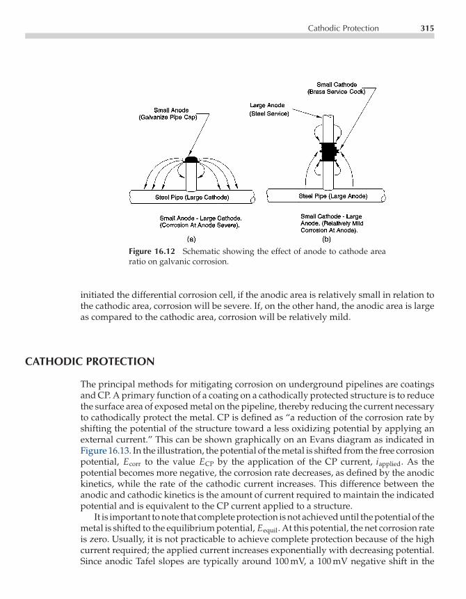
P1: FCECE003-16 CE003-Peabody September 6, 2000 11:56 Char Count= 0
Cathodic Protection 315
Figure 16.12 Schematic showing the effect of anode to cathode arearatio on galvanic corrosion.
initiated the differential corrosion cell, if the anodic area is relatively small in relation tothe cathodic area, corrosion will be severe. If, on the other hand, the anodic area is largeas compared to the cathodic area, corrosion will be relatively mild.
CATHODIC PROTECTION
The principal methods for mitigating corrosion on underground pipelines are coatingsand CP. A primary function of a coating on a cathodically protected structure is to reducethe surface area of exposed metal on the pipeline, thereby reducing the current necessaryto cathodically protect the metal. CP is defined as “a reduction of the corrosion rate byshifting the potential of the structure toward a less oxidizing potential by applying anexternal current.” This can be shown graphically on an Evans diagram as indicated inFigure 16.13. In the illustration, the potential of the metal is shifted from the free corrosionpotential, Ecorr to the value ECP by the application of the CP current, iapplied. As thepotential becomes more negative, the corrosion rate decreases, as defined by the anodickinetics, while the rate of the cathodic current increases. This difference between theanodic and cathodic kinetics is the amount of current required to maintain the indicatedpotential and is equivalent to the CP current applied to a structure.
It is important to note that complete protection is not achieved until the potential of themetal is shifted to the equilibrium potential, Eequil. At this potential, the net corrosion rateis zero. Usually, it is not practicable to achieve complete protection because of the highcurrent required; the applied current increases exponentially with decreasing potential.Since anodic Tafel slopes are typically around 100 mV, a 100 mV negative shift in the

P1: FCECE003-16 CE003-Peabody September 6, 2000 11:56 Char Count= 0
316 Fundamentals of Corrosion
Figure 16.13 Evans diagram demonstrating mechanism of CP.
potential will decrease the corrosion rate by a factor of 10. This magnitude of decreaseis typically considered to be adequate to protect most structures.
The required shift in potential can be achieved by means of an external power source(referred to as impressed current CP) or by utilizing a sacrificial anode. The impressedcurrent system uses a power supply, referred to as a rectifier, and an anode buried inthe ground to impress a current on the structure. The sacrificial anode system uses thegalvanic relationship between a sacrificial anode material, such as zinc or magnesium,and the pipe steel to supply the required CP current.
ENVIRONMENTAL POLARIZATION
The concepts presented for CP are fundamentally correct at the instant that CP is appliedbut are too simplistic to consider the time-dependant behavior of a cathodically protected

P1: FCECE003-16 CE003-Peabody September 6, 2000 11:56 Char Count= 0
Environmental Polarization 317
underground structure. At the surface of a structure under CP, a number of changes in theenvironment occur that are beneficial in mitigating corrosion. They have been referredto as environmental polarization. As shown in Figure 16.13, the rate of the reductionreaction is increased when the CP is applied. The reduction reactions generate OH− orconsume H+
O2 + 2H2O+ 4e− → 4OH− (3)
2H+ + 2e− → H2 (5)
2H2O+ 2e− → 2OH− +H2 (20)
Thus, an increase in the rate of these reactions causes a pH increase to occur at themetal surface, creating a less acidic (more basic) environment. This pH increase is bene-ficial because the corrosion rate of steel decreases with increasing pH, even under freelycorroding conditions. The decrease in corrosion rate is the result of the formation of aprotective oxide film on the metal surface in the elevated pH environment, a processreferred to as passivation. On an Evans diagram, this process corresponds to an increasein the anodic Tafel slope and a resulting shift in the oxidation kinetics to the left. Theflow of electrical current also causes damaging negatively charged ions (anions), suchas chloride, to migrate from the metal surface.
P1: kundu/SPH P2: fceCE003-App-A CE003-Peabody November 9, 2000 16:49 Char Count= 0
AppendixANACE Glossary ofCorrosion-Related Terms
Courtesy of Technical Coordination Committee and Reference Publications Committee.
AAbrasive Small particles of materialthat are propelled at high velocity toimpact a surface during abrasive blastcleaning.
Abrasive Blast Cleaning Cleaning androughening of a surface produced by thehigh-velocity impact of an abrasive that ispropelled by the discharge of pressurizedfluid from a blast nozzle or by a mechan-ical device such as a centrifugal blast-ing wheel. (Also referred to as AbrasiveBlasting.)
Accelerator A chemical substance thatincreases the rate at which a chemicalreaction (e.g., curing) would otherwiseoccur.
Acrylic Type of resin polymerized fromacrylic acid, methacrylic acid, esters ofthese acids, or acrylonitrile.
Activator A chemical substance thatinitiates and accelerates a chemical reac-tion (e.g., curing). Heat and radiation mayalso serve as activators for some chemicalreactions.
Active (1) The negative direction ofelectrode potential. (2) A state of a metalthat is corroding without significant in-fluence of reaction product.
Aeration Cell [See Differential AerationCell.]
Air Drying Process by which an ap-plied wet coat converts to a dry coatingfilm by evaporation of solvent or reactionwith oxygen as a result of simple expo-sure to air without intentional additionof heat or a curing agent.
Airless Spraying Process of sprayingcoating liquids using hydraulic pressure,not air pressure, to atomize.
Alkyd Type of resin formed by the reac-tion of polyhydric alcohols and polybasic
319

P1: kundu/SPH P2: fceCE003-App-A CE003-Peabody November 9, 2000 16:49 Char Count= 0
320 NACE Glossary of Corrosion-Related Terms
acids, part of which is derived from satu-rated or unsaturated oils or fats.
Alligatoring Pronounced wide crack-ing over the surface of a coating, whichhas the appearance of alligator hide.
Amphoteric Metal A metal that is sus-ceptible to corrosion in both acid andalkaline environments.
Anaerobic Free of air or uncombinedoxygen.
Anion A negatively charged ion thatmigrates through the electrolyte towardthe anode under the influence of a poten-tial gradient.
Anode The electrode of an electrochem-ical cell at which oxidation occurs. Elec-trons flow away from the anode in theexternal circuit. Corrosion usually occursand metal ions enter the solution at theanode.
Anode Cap An electrical insulating ma-terial placed over the end of the anode atthe lead wire connection.
Anode Corrosion Efficiency The ratioof the actual corrosion (mass loss) of ananode to the theoretical corrosion (massloss) calculated from the quantity of elec-tricity that has passed between the anodeand cathode using Faraday’s law.
Anodic Inhibitor A chemical substancethat prevents or reduces the rate of theanodic or oxidation reaction.
Anodic Polarization The change of theelectrode potential in the noble (positive)direction caused by current across theelectrode/electrolyte interface. [See Po-larization.]
Anodic Protection Polarization to amore oxidizing potential to achieve a
reduced corrosion rate by the promotionof passivity.
Anodizing Oxide coating formed on ametal surface (generally aluminum) by anelectrolytic process.
Anolyte The electrolyte adjacent to theanode of an electrochemical cell.
Antifouling Preventing fouling. [SeeFouling.]
Attenuation Electrical losses in a con-ductor caused by current flow in theconductor.
Auger Electron Spectroscopy Analyt-ical technique in which the samplesurface is irradiated with low-energyelectrons and the energy spectrum ofelectrons emitted from the surface ismeasured.
Austenitic Steel A steel whose mi-crostructure at room temperature consistspredominantly of austenite.
Auxiliary Electrode An electrode, usu-ally made from a noncorroding material,which is commonly used in polarizationstudies to pass current to or from a testelectrode.
BBackfill Material placed in a hole to fillthe space around the anodes, vent pipe,and buried components of a cathodicprotection system.
Barrier Coating (1) A coating that has ahigh resistance to permeation of liquidsand/or gases. (2) A coating that is ap-plied over a previously coated surface to

P1: kundu/SPH P2: fceCE003-App-A CE003-Peabody November 9, 2000 16:49 Char Count= 0
NACE Glossary of Corrosion-Related Terms 321
prevent damage to the underlying coat-ing during subsequent handling.
Beach Marks The characteristic mark-ings on the fracture surfaces producedby fatigue crack propagation (also knownas clamshell marks, conchoidal marks, andarrest marks).
Binder The nonvolatile portion of thevehicle of a formulated coating material.
Bituminous Coating An asphalt orcoal-tar compound used to provide a pro-tective coating for a surface.
Blast Angle (1) The angle of the blastnozzle with reference to the surface dur-ing abrasive blast cleaning. (2) The angleof the abrasive particles propelled froma centrifugal blasting wheel with refer-ence to the surface being abrasive blastcleaned.
Blowdown (1) Injection of air or waterunder high pressure through a tube tothe anode area for the purpose of purgingthe annular space and possibly correctinghigh resistance caused by gas blockage.(2) In conjunction with boilers or coolingtowers, the process of discharging a sig-nificant portion of the aqueous solutionin order to remove accumulated salts, de-posits, and other impurities.
Blushing Whitening and loss of glossof a coating, usually organic, caused bymoisture (also known as blooming).
Brittle Fracture Fracture with little orno plastic deformation.
Brush-Off Blast Cleaned Surface Abrush-off blast cleaned surface, whenviewed without magnification, shall befree of all visible oil, grease, dirt, dust,loose mill scale, loose rust, and loosecoating. Tightly adherent mill scale, rust,
and coating may remain on the surface.Mill scale, rust, and coating are consid-ered tightly adherent if they cannot be re-moved by lifting with a dull putty knife.[See NACE No. 4/SSPC-SP 7.]
CCalcareous Coating A layer consistingof calcium carbonate and other salts de-posited on the surface. When the surfaceis cathodically polarized as in cathodicprotection, this layer is the result of theincreased pH adjacent to the protectedsurface.
Calcareous Deposit [See CalcareousCoating.]
Case Hardening Hardening a ferrousalloy so that the outer portion, or case, ismade substantially harder than the innerportion, or core. Typical processes are car-burizing, cyaniding, carbo-nitriding, ni-triding, induction hardening, and flamehardening.
Casein Paint Water-thinned paint withvehicle derived from milk.
Catalyst A chemical substance, usuallypresent in small amounts relative to thereactants, that increases the rate at whicha chemical reaction (e.g., curing) wouldotherwise occur, but is not consumed inthe reaction.
Cathode The electrode of an electro-chemical cell at which reduction is theprincipal reaction. Electrons flow towardthe cathode in the external circuit.
Cathodic Corrosion Corrosion result-ing from a cathodic condition of a struc-ture, usually caused by the reaction of an

P1: kundu/SPH P2: fceCE003-App-A CE003-Peabody November 9, 2000 16:49 Char Count= 0
322 NACE Glossary of Corrosion-Related Terms
amphoteric metal with the alkaline prod-ucts of electrolysis.
Cathodic Disbondment The destruc-tion of adhesion between a coating andthe coated surface caused by products ofa cathodic reaction.
Cathodic Inhibitor A chemical sub-stance that prevents or reduces the rateof the cathodic or reduction reaction.
Cathodic Polarization The change ofthe electrode potential in the active (neg-ative) direction caused by current acrossthe electrode/electrolyte interface. [SeePolarization.]
Cathodic Protection A technique to re-duce the corrosion of a metal surface bymaking that surface the cathode of anelectrochemical cell.
Catholyte The electrolyte adjacent tothe cathode of an electrochemical cell.
Cation A positively charged ion thatmigrates through the electrolyte towardthe cathode under the influence of a po-tential gradient.
Cavitation The formation and rapidcollapse of cavities or bubbles within aliquid which often results in damage to amaterial at the solid/liquid interface un-der conditions of severe turbulent flow.
Cell [See Electrochemical Cell.]
Cementation The introduction of oneor more elements into the surface layerof a metal by diffusion at high temper-ature. (Examples of cementation includecarburizing [introduction of carbon], ni-triding [introduction of nitrogen], andchromizing [introduction of chromium].)
Chalking The development of loose, re-movable powder (pigment) at the surface
of an organic coating, usually caused byweathering.
Checking The development of slightbreaks in a coating which do not pene-trate to the underlying surface.
Chemical Conversion Coating An ad-herent reaction product layer on a metalsurface formed by reaction with a suit-able chemical to provide greater corro-sion resistance to the metal and increaseadhesion of coatings applied to the metal.(Example is an iron phosphate coating onsteel, developed by reaction with phos-phoric acid.)
Chevron Pattern A V-shaped patternon a fatigue or brittle-fracture surface.The pattern can also be one of straightradial lines on cylindrical specimens.
Chloride Stress Corrosion CrackingCracking of a metal under the combinedaction of tensile stress and corrosion in thepresence of chlorides and an electrolyte(usually water).
Coat One layer of a coating applied to asurface in a single continuous applicationto form a uniform film when dry.
Coating A liquid, liquefiable, or mas-tic composition that, after application toa surface, is converted into a solid pro-tective, decorative, or functional adherentfilm.
Coating System The complete numberand types of coats applied to a substratein a predetermined order. (When used ina broader sense, surface preparation, pre-treatments, dry film thickness, and man-ner of application are included.)
Cold Shut Horizontal surface disconti-nuity caused by solidification of a portionof a meniscus during the progressive

P1: kundu/SPH P2: fceCE003-App-A CE003-Peabody November 9, 2000 16:49 Char Count= 0
NACE Glossary of Corrosion-Related Terms 323
filling of a mold, which is later coveredwith more solidifying metal as the moltenmetal level rises. Cold shuts generally oc-cur at corners remote from the point ofpour.
Commercial Blast Cleaned Surface Acommercial blast cleaned surface, whenviewed without magnification, shall befree of all visible oil, grease, dust, dirt,mill scale, rust, coating, oxides, corrosionproducts, and other foreign matter. Ran-dom staining shall be limited to no morethan 33 percent of each unit area (ap-proximately 58 cm2 [9.0 in.2]) of surfaceand may consist of light shadows, slightstreaks, or minor discolorations causedby stains of rust, stains of mill scale, orstains of previously applied coating. [SeeNACE No. 3/SSPC-SP 6.]
Concentration Cell An electrochemicalcell, the electromotive force of which iscaused by a difference in concentration ofsome component in the electrolyte. (Thisdifference leads to the formation of dis-crete cathodic and anodic regions.)
Concentration Polarization That por-tion of polarization of a cell producedby concentration changes resulting frompassage of current though the electrolyte.
Conductive Coating (1) A coating thatconducts electricity. (2) An electricallyconductive, mastic-like material used asan impressed current anode on reinforcedconcrete surfaces.
Contact Corrosion [See Galvanic Corro-sion.]
Continuity Bond A connection, usuallymetallic, that provides electrical continu-ity between structures that can conductelectricity.
Continuous Anode A single anodewith no electrical discontinuities.
Conversion Coating [See Chemical Con-version Coating.]
Corrosion The deterioration of a mate-rial, usually a metal, that results from areaction with its environment.
Corrosion Fatigue Fatigue-type crack-ing of metal caused by repeated or fluctu-ating stresses in a corrosive environmentcharacterized by shorter life than wouldbe encountered as a result of either therepeated or fluctuating stress alone or thecorrosive environment alone.
Corrosion Inhibitor A chemical sub-stance or combination of substances that,when present in the environment, pre-vents or reduces corrosion.
Corrosion Potential (Ecorr) The poten-tial of a corroding surface in an electrolyterelative to a reference electrode underopen-circuit conditions (also known asrest potential, open-circuit potential, or freelycorroding potential).
Corrosion Rate The rate at which cor-rosion proceeds.
Corrosion Resistance Ability of a ma-terial, usually a metal, to withstand cor-rosion in a given system.
Corrosiveness The tendency of an en-vironment to cause corrosion.
Counter Electrode [See Auxiliary Elec-trode.]
Counterpoise A conductor or systemof conductors arranged beneath a powerline, located on, above, or most fre-quently, below the surface of the earthand connected to the footings of the tow-ers or poles supporting the power line.

P1: kundu/SPH P2: fceCE003-App-A CE003-Peabody November 9, 2000 16:49 Char Count= 0
324 NACE Glossary of Corrosion-Related Terms
Couple [See Galvanic Couple.]
Cracking (of Coating) Breaks in a coat-ing that extend through to the substrate.
Crazing A network of checks or cracksappearing on the surface of a coating.
Creep Time-dependent strain occur-ring under stress.
Crevice Corrosion Localized corrosionof a metal surface at, or immediately ad-jacent to, an area that is shielded from fullexposure to the environment because ofclose proximity of the metal to the surfaceof another material.
Critical Humidity The relative humid-ity above which the atmospheric corro-sion rate of some metals increases sharply.
Critical Pitting Potential (Ep, Epp) Thelowest value of oxidizing potential (volt-age) at which pits nucleate and grow. Thevalue depends on the test method used.
Curing Chemical process of developingthe intended properties of a coating orother material (e.g., resin) over a periodof time.
Curing Agent A chemical substanceused for curing a coating or other material(e.g., resin). [Also referred to as Hardener.]
Current Density The current to or froma unit area of an electrode surface.
Current Efficiency The ratio of the elec-trochemical equivalent current densityfor a specific reaction to the total appliedcurrent density.
DDC Decoupling Device A device usedin electrical circuits that allows the flow
of alternating current (AC) in both direc-tions and stops or substantially reducesthe flow of direct current (DC).
Dealloying The selective corrosion ofone or more components of a solid solu-tion alloy (also known as parting or selec-tive dissolution).
Decomposition Potential The poten-tial (voltage) on a metal surface necessaryto decompose the electrolyte of an electro-chemical cell or a component thereof.
Decomposition Voltage [See Decompo-sition Potential.]
Deep Groundbed One or more anodesinstalled vertically at a nominal depth of15 m (50 ft) or more below the earth’s sur-face in a drilled hole for the purpose ofsupplying cathodic protection.
Depolarization The removal of factorsresisting the current in an electrochemicalcell.
Deposit Attack Corrosion occurringunder or around a discontinuous depositon a metallic surface (also known as poul-tice corrosion).
Dezincification A corrosion phenome-non resulting in the selective removal ofzinc from copper-zinc alloys. (This phe-nomenon is one of the more commonforms of dealloying.)
Dielectric Coating A coating that doesnot conduct electricity.
Dielectric Shield An electrically non-conductive material, such as a coating,sheet or pipe, that is placed betweenan anode and an adjacent cathode, usu-ally on the cathode, to improve cur-rent distribution in a cathodic protectionsystem.
P1: kundu/SPH P2: fceCE003-App-A CE003-Peabody November 9, 2000 16:49 Char Count= 0
NACE Glossary of Corrosion-Related Terms 325
Differential Aeration Cell An electro-chemical cell, the electromotive force ofwhich is due to a difference in air (oxygen)concentration at one electrode as com-pared with that at another electrode of thesame material.
Diffusion-Limited Current DensityThe current density that correspondsto the maximum transfer rate that aparticular species can sustain because ofthe limitation of diffusion (often referredto as limiting current density).
Disbondment The loss of adhesion be-tween a coating and the substrate.
Double Layer The interface between anelectrode or a suspended particle andan electrolyte created by charge-chargeinteraction leading to an alignment ofoppositely charged ions at the surfaceof the electrode or particle. The simplestmodel is represented by a parallel platecondenser.
Drainage Conduction of electric cur-rent from an underground or submergedmetallic structure by means of a metallicconductor.
Driving Potential Difference in poten-tial between the anode and the steel struc-ture.
Drying Oil An oil capable of conver-sion from a liquid to a solid by slow reac-tion with oxygen in the air.
EElastic Deformation Changes of di-mensions of a material upon the appli-cation of a stress within the elastic range.Following the release of an elastic stress,
the material returns to its original dimen-sions without any permanent deforma-tion.
Elastic Limit The maximum stress towhich a material may be subjected with-out retention of any permanent deforma-tion after the stress is removed.
Elasticity The property of a materialthat allows it to recover its original di-mensions following deformation by astress below its elastic limit.
Electrical Isolation The condition ofbeing electrically separated from othermetallic structures or the environment.
Electrochemical Cell A system consist-ing of an anode and a cathode immersedin an electrolyte so as to create an electri-cal circuit. The anode and cathode maybe different metals or dissimilar areas onthe same metal surface.
Electrochemical Equivalent The massof an element or group of elements oxi-dized or reduced at 100% efficiency by thepassage of a unit quantity of electricity.
Electrochemical Potential The partialderivative of the total electrochemical freeenergy of a constituent with respect tothe number of moles of this constituentwhere all other factors are kept constant.It is analogous to the chemical potentialof a constituent except that it includesthe electrical as well as chemical contri-butions to the free energy.
Electrode A conductor used to establishcontact with an electrolyte and throughwhich current is transferred to or from anelectrolyte.
Electrode Potential The potential ofan electrode in an electrolyte as mea-sured against a reference electrode. (The

P1: kundu/SPH P2: fceCE003-App-A CE003-Peabody November 9, 2000 16:49 Char Count= 0
326 NACE Glossary of Corrosion-Related Terms
electrode potential does not include anyresistance losses in potential in either theelectrolyte or the external circuit. It repre-sents the reversible work to move a unit ofcharge from the electrode surface throughthe electrolyte to the reference electrode.)
Electrokinetic Potential A potentialdifference in a solution caused by resid-ual, unbalanced charge distribution in theadjoining solution, producing a doublelayer. The electrokinetic potential is dif-ferent from the electrode potential in thatit occurs exclusively in the solution phase.This potential represents the reversiblework necessary to bring a unit chargefrom infinity in the solution up to the in-terface in question but not through theinterface (also known as zeta potential).
Electrolyte A chemical substance con-taining ions that migrate in an electricfield.
Electrolytic Cleaning A process for re-moving soil, scale, or corrosion productsfrom a metal surface by subjecting themetal as an electrode to an electric cur-rent in an electrolytic bath.
Electromotive Force Series A list of el-ements arranged according to their stan-dard electrode potentials, the sign beingpositive for elements whose potentialsare cathodic to hydrogen and negative forthose anodic to hydrogen.
Ellipsometry An optical analyticaltechnique employing plane-polarizedlight to study films.
Embrittlement Loss of ductility of amaterial resulting from a chemical orphysical change.
EMF Series See Electromotive Force Series.
Enamel (1) A paint that dries to ahard, glossy surface. (2) A coating that is
characterized by an ability to form asmooth, durable film.
End Effect The more rapid loss of anodematerial at the end of an anode, comparedwith other surfaces of the anode, resultingfrom higher current density.
Endurance Limit The maximum stressthat a material can withstand for an in-finitely large number of fatigue cycles.
Environment The surroundings or con-ditions (physical, chemical, mechanical)in which a material exists.
Environmental Cracking Brittle frac-ture of a normally ductile material inwhich the corrosive effect of the environ-ment is a causative factor.
Environmental cracking is a generalterm that includes all of the terms listedbelow. The definitions of these terms arelisted elsewhere in the Glossary:
Corrosion fatigueHydrogen embrittlementHydrogen-induced cracking—(stepwise
cracking)Hydrogen stress crackingLiquid metal crackingStress corrosion crackingSulfide stress cracking
The following terms have been used inthe past in connection with environmen-tal cracking but are now obsolete andshould not be used:
Caustic embrittlementDelayed crackingLiquid metal embrittlementSeason crackingStatic fatigueSulfide corrosion crackingSulfide stress corrosion cracking
Epoxy Type of resin formed by the re-action of aliphatic or aromatic polyols

P1: kundu/SPH P2: fceCE003-App-A CE003-Peabody November 9, 2000 16:49 Char Count= 0
NACE Glossary of Corrosion-Related Terms 327
(like bisphenol) with epichlorohydrinand characterized by the presence of re-active oxirane end groups.
Equilibrium Potential The potential ofan electrode in an electrolyte at which theforward rate of a given reaction is exactlyequal to the reverse rate; the electrodepotential with reference to a standardequilibrium, as defined by the Nernstequation.
Erosion The progressive loss of mate-rial from a solid surface due to mechan-ical interaction between that surface anda fluid, a multicomponent fluid, or solidparticles carried with the fluid.
Erosion-Corrosion A conjoint actioninvolving corrosion and erosion in thepresence of a moving corrosive fluid or amaterial moving through the fluid, lead-ing to accelerated loss of material.
Exchange Current The rate at which ei-ther positive or negative charges are en-tering or leaving the surface when an elec-trode reaches dynamic equilibrium in anelectrolyte.
Exfoliation Corrosion Localized sub-surface corrosion in zones parallel to thesurface that result in thin layers of un-corroded metal resembling the pages of abook.
External Circuit The wires, connectors,measuring devices, current sources, etc.,that are used to bring about or measurethe desired electrical conditions within anelectrochemical cell. It is this portion ofthe cell through which electrons travel.
FFatigue The phenomenon leading tofracture of a material under repeated or
fluctuating stresses having a maximumvalue less than the tensile strength of thematerial.
Fatigue Strength The maximum stressthat can be sustained for a specified num-ber of cycles without failure.
Fault Current A current that flows fromone conductor to ground or to anotherconductor due to an abnormal connec-tion (including an arc) between the two.A fault current flowing to ground may becalled a ground fault current.
Ferrite The body-centered cubic crys-talline phase of iron-based alloys.
Ferritic Steel A steel whose microstruc-ture at room temperature consists pre-dominantly of ferrite.
Filiform Corrosion Corrosion that oc-curs under a coating in the form of ran-domly distributed thread-like filaments.
Film A thin, not necessarily visiblelayer of material.
Finish Coat [See Topcoat.]
Forced Drainage Drainage applied tounderground or submerged metallicstructures by means of an applied elec-tromotive force or sacrificial anode.
Foreign Structure Any metallic struc-ture that is not intended as a part of asystem under cathodic protection.
Fouling An accumulation of deposits.This includes accumulation and growthof marine organisms on a submergedmetal surface and the accumulation ofdeposits (usually inorganic) on heat ex-changer tubing.
Fractography Descriptive treatment offracture, especially in metals, with spe-cific reference to photographs of the frac-ture surface.

P1: kundu/SPH P2: fceCE003-App-A CE003-Peabody November 9, 2000 16:49 Char Count= 0
328 NACE Glossary of Corrosion-Related Terms
Fracture Mechanics A quantitativeanalysis for evaluating structural relia-bility in terms of applied stress, cracklength, and specimen geometry.
Free Machining The machining charac-teristics of an alloy to which an ingre-dient has been introduced to give smallbroken chips, lower power consump-tion, better surface finish, and longer toollife.
Fretting Corrosion Deterioration at theinterface of two contacting surfaces underload which is accelerated by their relativemotion.
Furan Type of resin formed by the poly-merization or polycondensation of fur-furyl, furfuryl alcohol, or other com-pounds containing a furan ring.
GGalvanic Anode A metal that providessacrificial protection to another metal thatis more noble when electrically coupledin an electrolyte. This type of anode isthe electron source in one type of cathodicprotection.
Galvanic Corrosion Accelerated corro-sion of a metal because of an electricalcontact with a more noble metal or non-metallic conductor in a corrosive elec-trolyte.
Galvanic Couple A pair of dissimilarconductors, commonly metals, in electri-cal contact in an electrolyte.
Galvanic Current The electric currentbetween metals or conductive nonmetalsin a galvanic couple.
Galvanic Series A list of metals andalloys arranged according to their corro-sion potentials in a given environment.
Galvanostatic Refers to an experimen-tal technique whereby an electrode ismaintained at a constant current in anelectrolyte.
General Corrosion Corrosion that isdistributed more or less uniformly overthe surface of a material.
Graphitic Corrosion Deterioration ofgray cast iron in which the metallic con-stituents are selectively leached or con-verted to corrosion products, leaving thegraphite intact.
Graphitization The formation of gra-phite in iron or steel, usually from decom-position of iron carbide at elevated tem-peratures. [Should not be used as a termto describe graphitic corrosion.]
Grit Small particles of hard material(e.g., iron, steel, or mineral) with irregu-lar shapes that are commonly used as anabrasive in abrasive blast cleaning.
Grit Blasting Abrasive blast cleaningusing grit as the abrasive.
Groundbed One or more anodes insta-lled below the earth’s surface for the pur-pose of supplying cathodic protection.
HHalf-Cell A pure metal in contact witha solution of known concentration of itsown ion, at a specific temperature, de-velops a potential that is characteristicand reproducible; when coupled withanother half-cell, an overall potential

P1: kundu/SPH P2: fceCE003-App-A CE003-Peabody November 9, 2000 16:49 Char Count= 0
NACE Glossary of Corrosion-Related Terms 329
that is the sum of both half-cells de-velops.
Hand Tool Cleaning Removal of looserust, loose mill scale, and loose paintto degree specified, by hand chipping,scraping, sanding, and wire brushing.[See SSPC-SP 2.]
Hardener [See Curing Agent.]
Heat-Affected Zone That portion of thebase metal that is not melted during braz-ing, cutting, or welding, but whose mi-crostructure and properties are altered bythe heat of these processes.
Heat Treatment Heating and cooling asolid metal or alloy in such a way as toobtain desired properties. Heating for thesole purpose of hot working is not consid-ered heat treatment.
High-Pressure Water Cleaning Watercleaning performed at pressures from 34to 70 MPa (5,000 to 10,000 psig).
High-Pressure Water Jetting Water jet-ting performed at pressures from 70 to 170MPa (10,000 to 25,000 psig).
High-Temperature Hydrogen AttackA loss of strength and ductility of steelby high-temperature reaction of absorbedhydrogen with carbides in the steel, re-sulting in decarburization and internalfissuring.
Holiday A discontinuity in a protectivecoating that exposes unprotected surfaceto the environment.
Hydrogen Blistering The formation ofsubsurface planar cavities, called hydro-gen blisters, in a metal resulting fromexcessive internal hydrogen pressure.Growth of near-surface blisters in low-strength metals usually results in surfacebulges.
Hydrogen Embrittlement A loss ofductility of a metal resulting from absorp-tion of hydrogen.
Hydrogen-Induced Cracking Stepwiseinternal cracks that connect adjacent hy-drogen blisters on different planes in themetal, or to the metal surface (also knownas stepwise cracking).
Hydrogen Overvoltage Overvoltageassociated with the liberation of hydro-gen gas.
Hydrogen Stress Cracking Crackingthat results from the presence of hydro-gen in a metal in combination with ten-sile stress. It occurs most frequently withhigh-strength alloys.
IImpingement Corrosion A form oferosion-corrosion generally associatedwith the local impingement of a high-velocity, flowing fluid against a solidsurface.
Impressed Current An electric currentsupplied by a device employing a powersource that is external to the electrodesystem. (An example is direct current forcathodic protection.)
Inclusion A nonmetallic phase such asan oxide, sulfide, or silicate particle in ametal.
Inorganic Zinc-Rich Coating Coatingcontaining a metallic zinc pigment (typi-cally 75 wt% zinc or more in the dry film)in an inorganic vehicle.
Intercrystalline Corrosion [See Inter-granular Corrosion.]

P1: kundu/SPH P2: fceCE003-App-A CE003-Peabody November 9, 2000 16:49 Char Count= 0
330 NACE Glossary of Corrosion-Related Terms
Interdendritic Corrosion Corrosive at-tack of cast metals that progresses prefer-entially along paths between dendrites.
Intergranular Corrosion Preferentialcorrosion at or along the grain boundariesof a metal (also known as intercrystallinecorrosion).
Intergranular Stress Corrosion CrackingStress corrosion cracking in which thecracking occurs along grain boundaries.
Internal Oxidation The formation ofisolated particles of oxidation productsbeneath the metal surface.
Intumescence The swelling or bub-bling of a coating usually caused byheating. [The term is commonly usedin aerospace and fire-protection applica-tions.]
Ion An electrically charged atom orgroup of atoms.
Iron Rot Deterioration of wood in con-tact with iron-based alloys.
KKnife-Line Attack Intergranular corro-sion of an alloy along a line adjoining orin contact with a weld after heating intothe sensitization temperature range.
LLamellar Corrosion [See ExfoliationCorrosion.]
Langelier Index A calculated satura-tion index for calcium carbonate that is
useful in predicting scaling behavior ofnatural water.
Line Currrent The direct current flow-ing on a pipeline.
Lining A coating or layer of sheet mate-rial adhered to or in intimate contact withthe interior surface of a container used toprotect the container against corrosion byits contents and/or to protect the contentsof the container from contamination bythe container material.
Liquid Metal Cracking Cracking of ametal caused by contact with a liquidmetal.
Long-Line Current Current though theearth between an anodic and a cathodicarea that returns along an undergroundmetallic structure.
Low-Carbon Steel Steel having lessthan 0.30% carbon and no intentional al-loying additions.
Low-Pressure Water Cleaning Watercleaning performed at pressures less than34 MPa (5,000 psig).
Luggin Probe A small tube or capillaryfilled with electrolyte, terminating closeto the metal surface of an electrode understudy, which is used to provide an ion-conducting path without diffusion be-tween the electrode under study and areference electrode.
MMartensite A hard supersaturatedsolid solution of carbon in iron char-acterized by an acicular (needle-like)microstructure.

P1: kundu/SPH P2: fceCE003-App-A CE003-Peabody November 9, 2000 16:49 Char Count= 0
NACE Glossary of Corrosion-Related Terms 331
Metal Dusting The catastrophic deteri-oration of a metal exposed to a carbona-ceous gas at elevated temperature.
Metallizing The coating of a surfacewith a thin metal layer by spraying, hotdipping, or vacuum deposition.
Mill Scale The oxide layer formed dur-ing hot fabrication or heat treatment ofmetals.
Mixed Potential A potential resultingfrom two or more electrochemical reac-tions occurring simultaneously on onemetal surface.
Modulus Of Elasticity A measure ofthe stiffness or rigidity of a material. It isactually the ratio of stress to strain in theelastic region of a material. If determinedby a tension or compression test, it is alsocalled Young’s Modulus or the coefficientof elasticity.
NNatural Drainage Drainage from anunderground or submerged metallicstructure to a more negative (more an-odic) structure, such as the negative busof a trolley substation.
Near-White Blast Cleaned Surface Anear-white blast cleaned surface, whenviewed without magnification, shall befree of all visible oil, grease, dust, dirt,mill scale, rust, coating, oxides, corrosionproducts, and other foreign matter. Ran-dom staining shall be limited to not morethan 5% of each unit area of surface (ap-proximately 58 cm2 [9.0 in.2]), and mayconsist of light shadows, slight streaks, orminor discolorations caused by stains of
rust, stains of mill scale, or stains of pre-viously applied coating. [See NACE No.2/SSPC-SP 10.]
Negative Return A point of connectionbetween the cathodic protection negativecable and the protected structure.
Nernst Equation An equation that ex-presses the exact electromotive force of anelectrochemical cell in terms of the activ-ities of products and reactants of the cell.
Nernst Layer The diffusion layer at thesurface of an electrode in which the con-centration of a chemical species is as-sumed to vary linearly from the value inthe bulk solution to the value at the elec-trode surface.
Noble The positive direction of elec-trode potential, thus resembling noblemetals such as gold and platinum.
Noble Metal (1) A metal that occurscommonly in nature in the free state.(2) A metal or alloy whose corrosionproducts are formed with a small nega-tive or a positive free-energy change.
Noble Potential A potential more ca-thodic (positive) than the standard hydro-gen potential.
Normalizing Heating a ferrous alloy toa suitable temperature above the trans-formation range (austenitizing), holdingat temperature for a suitable time, andthen cooling in still air to a tempera-ture substantially below the transforma-tion range.
OOpen-Circuit Potential The potentialof an electrode measured with respect to

P1: kundu/SPH P2: fceCE003-App-A CE003-Peabody November 9, 2000 16:49 Char Count= 0
332 NACE Glossary of Corrosion-Related Terms
a reference electrode or another electrodein the absence of current.
Organic Zinc-Rich Coating Coatingcontaining a metallic zinc pigment (typi-cally 75 wt% zinc or more in the dry film)in an organic resin.
Overvoltage The change in potential ofan electrode from its equilibrium orsteady-state value when current is ap-plied.
Oxidation (1) Loss of electrons by a con-stituent of a chemical reaction. (2) Corro-sion of a metal that is exposed to an oxi-dizing gas at elevated temperatures.
Oxidation-Reduction Potential Thepotential of a reversible oxidation-reduction electrode measured withrespect to a reference electrode, correctedto the hydrogen electrode, in a givenelectrolyte.
Oxygen Concentration Cell [See Differ-ential Aeration Cell.]
PPaint A pigmented liquid or resin ap-plied to a substrate as a thin layer thatis converted to an opaque solid film af-ter application. It is commonly used as adecorative or protective coating.
Paint System [See Coating System.]
Parting [See Dealloying.]
Passivation A reduction of the anodicreaction rate of an electrode involved incorrosion.
Passivation Potential [See Primary Pas-sive Potential.]
Passive (1) The positive direction ofelectrode potential. (2) A state of ametal in which a surface reaction productcauses a marked decrease in the corrosionrate relative to that in the absence of theproduct.
Passive-Active Cell An electrochemi-cal cell, the electromotive force of whichis caused by the potential difference be-tween a metal in an active state and thesame metal in a passive state.
Passivity The state of being passive.
Patina A thin layer of corrosion prod-uct, usually green, that forms on the sur-face of metals such as copper and copper-based alloys exposed to the atmosphere.
pH The negative logarithm of the hy-drogen ion activity written as:
pH = − log10 (a+H)
where a+H = hydrogen ion activity =the molar concentration of hydrogenions multiplied by the mean ion-activitycoefficient.
Pickling (1) Treating a metal in a chem-ical bath to remove scale and oxides(e.g., rust) from the surface. (2) Completeremoval of rust and mill scale by acidpickling, duplex pickling, or electrolyticpickling. [See SSPC-SP 8.]
Pickling Solution A chemical bath,usually an acid solution, used for pick-ling.
Pigment A solid substance, generally infine powder form, that is insoluble in thevehicle of a formulated coating material.It is used to impart color or other spe-cific physical or chemical properties to thecoating.
Pipe-To-Electrolyte Potential The po-tential difference between the pipe

P1: kundu/SPH P2: fceCE003-App-A CE003-Peabody November 9, 2000 16:49 Char Count= 0
NACE Glossary of Corrosion-Related Terms 333
metallic surface and electrolyte that ismeasured with reference to an electrodein contact with the electrolyte.
Pitting Localized corrosion of a metalsurface that is confined to a small areaand takes the form of cavities called pits.
Pitting Factor The ratio of the depth ofthe deepest pit resulting from corrosiondivided by the average penetration ascalculated from mass loss.
Plastic Deformation Permanent defor-mation caused by stressing beyond theelastic limit.
Plasticity The ability of a material to de-form permanently (nonelastically) with-out fracturing.
Polarization The change from the open-circuit potential as a result of currentacross the electrode/electrolyte interface.
Polarization Admittance The recipro-cal of polarization resistance.
Polarization Cell A DC decoupling de-vice consisting of two or more pairsof inert metallic plates immersed in anaqueous electrolyte. The electrical char-acteristics of the polarization cell arehigh resistance to DC potentials and lowimpedance of AC.
Polarization Curve A plot of currentdensity versus electrode potential fora specific electrode/electrolyte combina-tion.
Polarization Decay The decrease inelectrode potential with time resultingfrom the interruption of applied current.
Polarization Resistance The slope(dE/di) at the corrosion potential of apotential (E)-current density (i) curve.(The measured slope is usually in good
agreement with the true value of thepolarization resistance when the scanrate is low and any uncompensated resis-tance is small relative to the polarizationresistance.)
Polarized Potential The potentialacross the structure/electrolyte interfacethat is the sum of the corrosion potentialand the cathodic polarization.
Polyester Type of resin formed by thecondensation of polybasic and monoba-sic acids with polyhydric alcohols.
Postweld Heat Treatment Heating andcooling a weldment in such a way as toobtain desired properties.
Potential-pH Diagram A graphicalmethod of representing the regions ofthermodynamic stability of species formetal/electrolyte systems (also knownas Pourbaix diagram).
Potentiodynamic Refers to a techniquewherein the potential of an electrode withrespect to a reference electrode is varied ata selected rate by application of a currentthrough the electrolyte.
Potentiokinetic [See Potentiodynamic.]
Potentiostat An instrument for auto-matically maintaining a constant elec-trode potential.
Potentiostatic Refers to a technique formaintaining a constant electrode poten-tial.
Pot Life The elapsed time within whicha coating can be effectively applied afterall components of the coating have beenthoroughly mixed.
Poultice Corrosion [See Deposit Attack.]
Pourbaix Diagram [See Potential-pHDiagram.]

P1: kundu/SPH P2: fceCE003-App-A CE003-Peabody November 9, 2000 16:49 Char Count= 0
334 NACE Glossary of Corrosion-Related Terms
Power Tool Cleaning Removal of looserust, loose mill scale, and loose paint todegree specified by power tool chipping,descaling, sanding, wire brushing, andgrinding. [See SSPC-SP 3.]
Precipitation Hardening Hardeningcaused by the precipitation of a con-stituent from a supersaturated solidsolution.
Primary Passive Potential The poten-tial corresponding to the maximum ac-tive current density (critical anodic cur-rent density) of an electrode that exhibitsactive-passive corrosion behavior.
Prime Coat [See Primer.]
Primer A coating material intended tobe applied as the first coat on an uncoatedsurface. The coating is specifically formu-lated to adhere to and protect the surfaceas well as to produce a suitable surfacefor subsequent coats. [Also referred to asPrime Coat.]
Profile Anchor pattern on a surface pro-duced by abrasive blasting or acid treat-ment.
Protective Coating A coating appliedto a surface to protect the substrate fromcorrosion.
RReduction Gain of electrons by a con-stituent of a chemical reaction.
Reference Electrode An electrodewhose open-circuit potential is constantunder similar conditions of measure-ment, which is used for measuring therelative potentials of other electrodes.
Reference Half-Cell [See Reference Elec-trode.]
Relative Humidity The ratio, ex-pressed as a percentage, of the amount ofwater vapor present in a given volumeof air at a given temperature to theamount required to saturate the air atthat temperature.
Remote Earth A location on the earthfar enough from the affected structurethat the soil potential gradients associ-ated with currents entering the earth fromthe affected structure are insignificant.
Rest Potential [See Corrosion Potential.]
Reversible Potential [See EquilibriumPotential.]
Rimmed Steel An incompletely deoxi-dized steel. [Also called Rimming Steel.]
Riser (1) That section of pipeline ex-tending from the ocean floor up to an off-shore platform. (2) The vertical tube in asteam generator convection bank that cir-culates water and steam upward.
Rust Corrosion product consisting ofvarious iron oxides and hydrated ironoxides. (This term properly applies onlyto iron and ferrous alloys.)
Rust Bloom Discoloration indicatingthe beginning of rusting.
SSacking Scrubbing a mixture of a ce-ment mortar over the concrete surface us-ing a cement sack, gunny sack, or spongerubber float.
Sacrificial Protection Reduction of cor-rosion of a metal in an electrolyte by gal-vanically coupling it to a more anodicmetal (a form of cathodic protection).

P1: kundu/SPH P2: fceCE003-App-A CE003-Peabody November 9, 2000 16:49 Char Count= 0
NACE Glossary of Corrosion-Related Terms 335
Scaling (1) The formation at high tem-peratures of thick corrosion-product lay-ers on a metal surface. (2) The depositionof water-insoluble constituents on a metalsurface.
Scanning Electron Microscope Anelectron optical device that images topo-graphical details with maximum contrastand depth of field by the detection,amplification, and display of secondaryelectrons.
Sensitizing Heat Treatment A heattreatment, whether accidental, inten-tional, or incidental (as during welding),that causes precipitation of constituents(usually carbides) at grain boundaries, of-ten causing the alloy to become suscep-tible to intergranular corrosion or inter-granular stress corrosion cracking.
Shallow Groundbed One or more an-odes installed either vertically or horizon-tally at a nominal depth of less than 15 m(50 ft) for the purpose of supplying ca-thodic protection.
Shop Coat One or more coats applied ina shop or plant prior to shipment to thesite of erection or fabrication.
Shot Blasting Abrasive blast cleaningusing metallic (usually steel) shot as theabrasive.
Shot Peening Inducing compressivestresses in the surface layer of a materialby bombarding it with a selected medium(usually steel shot) under controlledconditions.
Sigma Phase An extremely brittle Fe-Crphase that can form at elevated tempera-tures in Fe-Cr-Ni and Ni-Cr-Fe alloys.
Slip A deformation process involvingshear motion of a specific set of crystal-lographic planes.
Slow Strain Rate Technique An ex-perimental technique for evaluating sus-ceptibility to environmental cracking. Itinvolves pulling the specimen to fail-ure in uniaxial tension at a controlledslow strain rate while the specimen is inthe test environment and examining thespecimen for evidence of environmentalcracking.
Slushing Compound Oil or greasecoatings used to provide temporary pro-tection against atmospheric corrosion.
Solution Heat Treatment Heating ametal to a suitable temperature andholding at that temperature long enoughfor one or more constituents to enterinto solid solution, then cooling rapidlyenough to retain the constituents insolution.
Solvent Cleaning Removal of oil,grease, dirt, soil, salts, and contaminantsby cleaning with solvent, vapor, alkali,emulsion, or steam. [See SSPC-SP 1.]
Spalling The spontaneous chipping,fragmentation, or separation of a surfaceor surface coating.
Standard Electrode Potential The re-versible potential for an electrode processwhen all products and reactions are atunit activity on a scale in which the poten-tial for the standard hydrogen referenceelectrode is zero.
Standard Jetting Water Water of suffi-cient purity and quality that it does notimpose additional contaminants on thesurface being cleaned and does not con-tain sediments or other impurities that aredestructive to the proper functioning ofwater jetting equipment.
Steel Shot Small particles of steel withspherical shape that are commonly used

P1: kundu/SPH P2: fceCE003-App-A CE003-Peabody November 9, 2000 16:49 Char Count= 0
336 NACE Glossary of Corrosion-Related Terms
as an abrasive in abrasive blast cleaningor as a selected medium for shot peening.
Stepwise Cracking [See Hydrogen-Induced Cracking.]
Stray Current Current through pathsother than the intended circuit.
Stray-Current Corrosion Corrosion re-sulting from current through paths otherthan the intended circuit, e.g., by any ex-traneous current in the earth.
Stress Corrosion Cracking Cracking ofa material produced by the combined ac-tion of corrosion and tensile stress (resid-ual or applied).
Stress Relieving (Thermal) Heating ametal to a suitable temperature, holdingat that temperature long enough to re-duce residual stresses, and then coolingslowly enough to minimize the develop-ment of new residual stresses.
Subsurface Corrosion [See InternalOxidation.]
Sulfidation The reaction of a metal oralloy with a sulfur-containing species toproduce a sulfur compound that formson or beneath the surface of the metal oralloy.
Sulfide Stress Cracking Cracking of ametal under the combined action of ten-sile stress and corrosion in the presenceof water and hydrogen sulfide (a form ofhydrogen stress cracking).
TTack Coat A thin wet coat applied to thesurface that is allowed to dry just until itis tacky before application of a thicker wet
coat. (Use of a tack coat allows applicationof thicker coats without sagging or runs.)
Tafel Plot A plot of the relationship be-tween the change in potential (E) and thelogarithm of the current density (log i) ofan electrode when it is polarized in boththe anodic and cathodic directions fromits open-circuit potential.
Tafel Slope The slope of the straight-line portion of the E log i curve on a Tafelplot. (The straight-line portion usually oc-curs at more than 50 mV from the open-circuit potential.)
Tarnish Surface discoloration of ametal resulting from formation of a filmof corrosion product.
Thermal Spraying A group of pro-cesses by which finely divided metallicor nonmetallic materials are deposited ina molten or semimolten condition to forma coating.
Thermogalvanic Corrosion Corrosionresulting from an electrochemical cellcaused by a thermal gradient.
Throwing Power The relationship be-tween the current density at a point ona surface and its distance from the coun-terelectrode. The greater the ratio of thesurface resistivity shown by the electrodereaction to the volume resistivity of theelectrolyte, the better is the throwingpower of the process.
Topcoat The final coat of a coating sys-tem. [Also referred to as Finish Coat.]
Transpassive The noble region of po-tential where an electrode exhibits ahigher-than-passive current density.
Tuberculation The formation of local-ized corrosion products scattered over the

P1: kundu/SPH P2: fceCE003-App-A CE003-Peabody November 9, 2000 16:49 Char Count= 0
NACE Glossary of Corrosion-Related Terms 337
surface in the form of knob-like moundscalled tubercles.
U-V-WUltimate Strength The maximumstress that a material can sustain.
Ultrahigh-Pressure Water Jetting Wa-ter jetting performed at pressures above170 MPa (25,000 psig.)
Underfilm Corrosion [See FiliformCorrosion.]
Vehicle The liquid portion of a formu-lated coating material.
Void (1) A holiday, hole, or skip in acoating. (2) A hole in a casting or welddeposit usually resulting from shrinkageduring cooling.
Wash Primer A thin, inhibiting primer,usually chromate pigmented, with apolyvinyl butyral binder.
Water Cleaning Use of pressurized wa-ter discharged from a nozzle to removeunwanted matter (e.g., dirt, scale, rust,coatings) from a surface.
Water Jetting Use of standard jettingwater discharged from a nozzle at pres-sures of 70 MPa (10,000 psig) or greaterto prepare a surface for coating or inspec-tion.
Weight Coating An external coatingapplied to a pipeline to counteract buoy-ancy.
White Metal Blast Cleaned Surface Awhite metal blast cleaned surface, when
viewed without magnification, shall befree of all visible oil, grease, dust, dirt,mill scale, rust, coating, oxides, corrosionproducts, and other foreign matter. [SeeNACE No. 1/SSPC-SP 5.]
Weld Decay Intergranular corrosion,usually of stainless steel or certain nickel-base alloys, that occurs as the result ofsensitization in the heat-affected zoneduring the welding operation. [This is nota preferred term.]
Wet Film Gauge Device for measuringwet film thickness of a coating.
Working Electrode The test or speci-men electrode in an electrochemical cell.
Wrought Metal in the solid conditionthat is formed to a desired shape by work-ing (rolling, extruding, forging, etc.), usu-ally at an elevated temperature.
X-Y-ZYield Point The stress on a materialat which the first significant permanentor plastic deformation occurs withoutan increase in stress. In some materials,particularly annealed low-carbon steels,there is a well-defined yield point fromthe straight line defining the modulus ofelasticity.
Yield Strength The stress at which amaterial exhibits a specified deviationfrom the proportionality of stress tostrain. The deviation is expressed in termsof strain by either the offset method (usu-ally at a strain of 0.2%) or the total-extension-under-load method (usually ata strain of 0.5%.)

P1: fceCE003-App-B CE003-Peabody November 9, 2000 14:39 Char Count= 4929
AppendixBAdditional Important Informationon Underground Corrosion Control
Copies of federal regulations concerning the installation and operation of undergroundpipelines are available as follows:Transportation of Natural and Other Gas by Pipeline: Minimum Safety Standards. Fed-eral Register, Vol. 35, Number 161, Part II, August 19, 1970. Title 49. Parts 190, 192.Transportation of Liquids by Pipeline. Federal Register, Vol. 35, No. 218, November 7,1970. Title 49. Parts 180, 195.Available from Department of Transportation, Office of Pipeline Safety, Washington,D.C. 20590.
NACE REFERENCED STANDARDS
Standard Standard TitleCoatingsMR0274-95 Material Requirements for Polyolefin Cold-Applied Tapes for Underground Sub-
merged Pipeline Coatings-Item No. 21301RP0185-96 Extruded Polyolefin Resin Coating Systems with Soft Adhesives for Underground
or Submerged Pipe-Item No. 21029RP0190-95 External Protective Coatings for Joints, Fittings, and Valves on Metallic Under-
ground or Submerged Pipelines and Piping Systems-Item No. 21042RP0399-99 Plant-Applied, External Coal Tar Enamel Pipe Coating System: Application,
Performance, and Quality Control-Item No. 21089RP0394-94 Application, Performance, and Quality Control of Plant-Applied, Fusion-Bonded
Epoxy External Pipe Coating-Item No. 21064RP0375-99 Wax Coating Systems for Underground Piping Systems-Item No. 21013
339
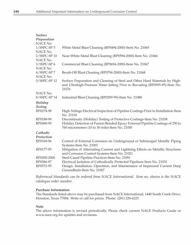
P1: fceCE003-App-B CE003-Peabody November 9, 2000 14:39 Char Count= 4929
340 Additional Important Information on Underground Corrosion Control
SurfacePreparationNACE No.1/SSPC-SP 5 White Metal Blast Cleaning (RP0494-2000)-Item No. 21065NACE No.2/SSPC-SP 10 Near-White Metal Blast Cleaning (RP0594-2000)-Item No. 21066NACE No.3/SSPC-SP 6 Commercial Blast Cleaning (RP0694-2000)-Item No. 21067NACE No.4/SSPC-SP 7 Brush-Off Blast Cleaning (RP0794-2000)-Item No. 21068NACE No.5/SSPC-SP 12 Surface Preparation and Cleaning of Steel and Other Hard Materials by High-
and Ultrahigh-Pressure Water Jetting Prior to Recoating (RP0595-95)-Item No.21076
NACE No.8/SSPC-SP 14 Industrial Blast Cleaning (RP0299-99)-Item No. 21088
HolidayTestingRP0274-98 High-Voltage Electrical Inspection of Pipeline Coatings Prior to Installation-Item
No. 21010RP0188-99 Discontinuity (Holiday) Testing of Protective Coatings-Item No. 21038RP0490-95 Holiday Detection of Fusion-Bonded Epoxy External Pipeline Coatings of 250 to
760 micrometers (10 to 30 mils)-Item No. 21045
CathodicProtectionRP0169-96 Control of External Corrosion on Underground or Submerged Metallic Piping
Systems-Item No. 21001RP0177-95 Mitigation of Alternating Current and Lightning Effects on Metallic Structures
and Corrosion Control Systems-Item No. 21021RP0200-2000 Steel-Cased Pipeline Practices-Item No. 21091RP0286-97 Electrical Isolation of Cathodically Protected Pipelines-Item No. 21032RP0572-95 Design, Installation, Operation, and Maintenance of Impressed Current Deep
Groundbeds-Item No. 21007
Referenced Standards can be ordered from NACE International. Item no. shown is the NACEcatalogue order number.
Purchase InformationThe Standards listed above may be purchased from NACE International, 1440 South Creek Drive,Houston, Texas 77084. Write or call for prices. Phone: (281) 228-6223.
NoteThe above information is revised periodically. Please check current NACE Products Guide orwww.nace.org for updates and revisions.

P1: FCECE003-ID CE003-Peabody November 3, 2000 12:50 Char Count= 18171
Index
AAcidity
bacteria and, 277–279pH values, 4, 90–91, 279soil and, 90–91, 317
Activation polarization, 304Adhesion tests, 10Aeration cell, 308–309Alkaline conditions, 11, 62, 64, 91Alternative power sources, 201–210Aluminum anodes, 177, 301Aluminum piping, 40, 62–63Ammeter clamps, 115–116Amphoteric materials, 64Anaerobic conditions, 66, 97, 280Anode systems
backfill and, 134–135, 184, 255cathodes and, 23, 277–299, 313–314connections and, 176deep anodes, 145–155, 268–269distributed, 144–145efficiency of, 177–178, 186galvanic, 23, 140–144, 177–199, 221–222ground beds, 140–144, 255–256high-potential, 28horizontal, 138–139impressed current, 144–145installation of, 193–199interference and, 221–222life of, 186–187, 269maintenance, 261–271
multiple anode bed, 193performance, 190–193resistance equation, 134size of, 313–314spacing of, 292–294suspension systems, 150types of, 166–169vertical, 132–133See also specific types
Anodic reaction, 2Antimony electrode, 122Area relationships, 313–314
BBack voltage, 135Backfills, 132–133, 134
anodes and, 184, 255cable trench, 256carbon, 150–151carbonaceous, 132, 139–140, 174, 256chemical, 184, 186, 255materials, 174–175, 196See also specific types
Bacteria, 273–284Bare lines, 92–93, 99Barnes method, 89, 90Bellhole surveys, 67, 97–98Beta profile, 230Biocides, 274Biofilms, 275, 276
341

P1: FCECE003-ID CE003-Peabody November 3, 2000 12:50 Char Count= 18171
342 Index
Blistering, 8Bolt insulation, 250Bond, drainage, 219–221, 233–236Butler-Volmer equation, 307
CCables
backfill and, 256ground bed, 255locators, 114resistance, 136trench for, 256types of, 175–176
Calibration records, 128Carbon backfill, 150–151Carbonaceous backfill, 132, 174, 256Carbonic acid solution, 277Cased crossings, 245–248
avoidance of, 36casing compounds, 271inspection of, 258maintenance of, 270–271short circuits, 247–248survey of, 262test methods, 245–248
Cast iron anodes, 168, 254Cast iron pipes, 49–62Casing end seals, 246Casing insulators, 246Cathodic protection (CP), 5, 21–48
alternative power sources, 201–210application of, 23–28bacteria and, 282bare lines, 44basic theory, 21–23coating and, 26–28cost of, 146, 285–292criteria for, 24–25, 49–64de-energizing, 56–57deep anodes, 145–155, 268–269definition of, 6disbondment, 28E-log I criteria, 62–63effectiveness of, 39–47foreign pipelines and, 41–43galvanic anodes, 23–24, 177–199,
221–222
ground beds and, 41–43impressed current, 23–24, 43, 157–176installation of, 255–259instrumentation, 101–129interference, 212–223maintenance procedures, 261–271mV criteria, 50–58, 60net protective criteria, 58–60overprotection, 56–57polarization and, 52–58potential shift, 50–58, 60power sources, 201–210rectifiers, 157–176shielding, 33stray current from, 211–236testing for, 92–100underground piping, 50–58See also specific problems, types
CCVTs. See Closed cycle vaporturbogenerators
Centralizers, 150Close ground beds, 30–32Close interval surveys, 71–73, 126–127Closed cycle vapor turbogenerators (CCVTs),
202–204Coal tar enamel (CTE), 8, 15Coatings, 7–20, 93–99
adhesion of, 8applicability, 8bacteria and, 281–282degradation of, 6dielectric, 8, 119disbonding, 281–282effectiveness of, 7–11function of, 6improper application, 11inspection of, 12–14maintenance, 265–266multi-layer systems, 8nontoxic, 9overprotection, 28pinholes, 119poorly-coated lines, 221recoating, 266repair of, 9, 12resistivity, 26soil stress and, 8–11, 265, 281specifications for, 10–12
P1: FCECE003-ID CE003-Peabody November 3, 2000 12:50 Char Count= 18171
Index 343
surveys of, 93–97, 265–266See also Holidays; specific problems, types
Coke breeze, 174, 256Compression couplings, 133, 176Computer surveys, 265Concentration polarization, 307Congested areas, 37–39Connection methods, 176Construction practices, 237–259, 287Coordinating committees, 236Copper-copper sulfate electrode, 25, 121–122Copper piping, 63–64Copper sulfate electrodes (CSE), 68, 124–128,
214, 302Cost estimates, 285–292Coupons, 120–124CP. See Cathodic protectionCracking, 307Crimp-type connections, 133, 176Crossings, foreign-line, 41–44, 213–215, 222,
262, 271CSE. See Copper sulfate electrodeCTE. See Coal tar enamelCurrent interrupters, 110–111, 113
DDeep anode systems, 145–155, 268–269Deep well beds, 268–269Delta voltage, 219Department of Environmental Resources
(DER), 7Department of Transportation-Office of
Pipeline Safety (DOT/OPS), 7Depolarization, 280DER. See Department of Environmental
ResourcesDielectric coatings, 8, 119Differential aeration cells, 308–310Differential corrosion cells, 2–5, 310–313Disbonding, 9, 11, 28Dissimilar metal piping, 63–64Distributed anodes, 144–145DOT/OPS. See Department of
Transportation-Office of PipelineSafety
Drainage bonds, 219–221, 233–236Dwight equations, 149
EE-log I curve criterion, 61–63Economic factors, 285–295Efficiency, of anodes, 177–178, 186Electric shielding, 33–39, 224–225Electrolysis switches, 262Electromagnetic conductivity method,
148Electromotive force (EMF), 298–299Embrittlement, 54EMF. See Electromotive forceEnamels, 8, 15Engine-generator systems, 201–202Environmental effects, 9Environmental polarization, 316–317Epoxies, 8, 17–18, 281–282Equilibrium potential, 303, 315Equipment vendors, 101Equivalent circuit, 30Evaluation techniques, 65–100Evans diagrams, 54, 305, 308, 315,
317Extrusion systems, 15–17
FFaraday constant, 298, 300Faraday’s law, 307Fatigue cracking, 8FBE. See Fusion-bonded epoxiesFerrous ion concentrations, 276Flanges, 249–250Flooding, 257Foreign line crossings, 41–44, 213–215,
222, 262, 271Four-pin method, 85–87, 105, 148Four-wire test points, 79–81, 239, 247Fuel cells, 210Fungi, 273–284Fusion-bonded epoxies (FBE), 8, 17–18,
281–282
GGalvanic anode systems, 23, 140–144,
177–199, 221–222, 288Galvanic corrosion, 310–312Galvanic series, 303–304Gas blocking, 269

P1: FCECE003-ID CE003-Peabody November 3, 2000 12:50 Char Count= 18171
344 Index
Gas turbines, 209Generators, 201–202Genetic engineering, 275Gibbs free energy, 297–298Graphite anodes, 166–167, 174–175Ground bed systems, 28–33
cables and, 255, 256cathodic protection, 41–43close, 30–32designing, 131–156galvanic anodes, 140–144impressed current systems, 132–140,
166–176installing, 256locating, 131–132maintenance of, 268–269stray current, 224–225vertical anodes, 133
Grounding cells, 252–254, 262Gypsum-bentonite backfill, 188
HHalf-cell electrodes, 2–3, 298Header wire, 193High-potential anodes, 28High-resistivity coating, 26Holidays, 5, 8
coatings and, 6, 266detection, 12, 118–120, 238–239foreign lines and, 215inspection and, 13–14
Horizontal anodes, 138Hotspot protection, 69, 180Hydrogen, 51, 97–98
IImpedance, 102Impressed current systems, 288
cathodic protection and, 23–24, 157–176deep anodes and, 145–146ground beds, 132–140, 166–176insulation, 259interference, 180survey and, 262
Inspections, 12–14, 257Installation procedures, 193–199, 219
Instrumentation, 101–129Insulation
barrier, 33–34buried wire and, 254couplings and, 10grounding cells, 252–254inspection, 116, 246, 258joints and, 176, 249–254, 258shielding and, 33–34zinc anode, 252–253
Interference, 40–41cathodic protection and, 212–223impressed current and, 180information on, 46–47stray current and, 219–224
Interrupters, 110–111, 113, 214Investment costs, 286Ion concentrations, 4, 276IR voltage drops, 50, 69Iron-oxidizing bacteria, 279Iron pipes, 49–62Iron sulfide, 276, 282Isolation surge protectors (ISP), 254ISP. See Isolation surge protectors
JJeeping of coatings, 12Joint insulation, 176, 249–254, 258
KKinetics, 304–308
LLeaks, pipeline, 39, 291Leapfrog technique, 75–76Lightning, 157–158, 252–254, 262Line current measurements, 77–84Liquid coating systems, 18Locators, for cables, 114Long-line current flow, 51, 83
MMagnesium anodes, 180–184, 188, 190–193,
223, 232, 301Magnetic disturbances, 236

P1: FCECE003-ID CE003-Peabody November 3, 2000 12:50 Char Count= 18171
Index 345
Maintenance procedures, 261–271, 287,294–295
Metal deposition, 278–279Metal-reducing bacteria (MRB), 275Metal reduction, 275, 280Meter accessories, 124MIC. See Microbiologically influenced
corrosionMicrobiologically influenced corrosion
(MIC), 97, 273–284Mill coated pipe, 15, 237–238Mill scale corrosion, 311Mixed-metal oxide anodes, 168Moisture content, of soil, 4Mortar/concrete systems, 36MRB. See Metal-reducing bacteriaMulti-layer systems, 8, 18–19Multimeters, 102Multiple anode bed, 193mV shift criteria, 50–61
NNational Electrical Code (NEC), 257National Insitute of Standards and
Technology (NIST), 128Natural gas systems, 204, 209NEC. See National Electrical CodeNernst equation, 300Net protective criterion, 49, 58–60Niobium, 172NIST. See National Institute of Standards and
TechnologyNoble metals, 3Null ampere test, 81
OOccupational Safety and Health
Administration (OSHA), 7Off-potentials, 28Ohmic voltage drops, 50Ohm’s law, 77–78OPS. See Department of
Transportation-Office of PipelineSafety
OSHA. See Occupational Safety and HealthAdministration
Over-the-line potential survey,69–73
Overprotection, 28, 51, 56–57Overvoltage, 304Oxidation, 1–2Oxide film, 317Oxygen, 1–2, 4, 279
PPE. See PolyethylenePeel strength, 9pH values, 4, 90–91, 277–279, 317Pipe-to-soil potential, 29, 56, 68, 71, 95,
102, 222, 302Pit gages, 108–109Pitting, 265, 280Plasmids, 275Plastic resins, 256Platinum anodes, 169–172Polarization, 55
cells, 262concentration, 307CP system, 52–58decay, 55definition of, 53, 304environmental, 316–317hydrogen, 97off-potential values, 55
Polyethylene (PE), 255, 281Polyolefin, 16–19, 281Polysaccharide materials, 274Polyvinyl chloride (PVC), 281Portable instruments, 122Potential shift criterion, 60–61Potential values, 3–4, 25, 71Power costs, 287Power sources, 201–210Priming, 12, 237Probe rods, 81–82, 247Pulse generators, 112–114PVC. See Polyvinyl chloride
RRail transit systems, 226–230Rankine cycle turbine, 202Recording instruments, 106–108

P1: FCECE003-ID CE003-Peabody November 3, 2000 12:50 Char Count= 18171
346 Index
Rectifiersconstant potential, 160efficiency of, 163–165installation details, 165maintenance, 266–268placement of, 257power costs, 287selection of, 157size of, 160–161specifications, 162–163transformers, 158
Reduction reaction, 1–2Reference electrodes, 3, 120–124, 301–302Reinforcing wire, 36–37Remote earth, 71–72, 146Remote ground beds, 28–33Resistance drop method, 77Resistivity testing, 105, 124–125
accessories, 124–125coatings and, 9drop method, 77resistance to earth, 135soil and, 84–90, 105–106, 148–149,
191–193voltmeters and, 102–103See also specific methods
Reverse current flow, 235Ribbon anodes, 197Rubber splicing compound, 256Rudenberg formula, 30
SSalts, in soils, 90Saturated solution, 128Sea water, 255Seals, 35, 151–152Selenium stacks, 159Shielding, 33–39, 219, 224–225Short circuits, 34–36, 247–248Side drain technique, 76–77Silicon diodes, 157, 159Six-wire test point, 239–240Soils
chemical analysis, 90–91deep formations, 148–149dissimilar, 312–313moisture content, 195
resistivities, 84–90, 105–106,148–149, 191–193
salts, 90sandy, 281stress, 8–11, 265, 281types, 313
Solar power systems, 206–207Solvent action, 255Spacing, of anodes, 292–294Spark gaps, 262Spin-bolt couplings, 176Spores, 274–275Steel piping, 49–62Storage batteries, 208Stray current, 40, 211–236Strip anodes, 197, 198Sulfate reduction, 275–277Sulfides, 276Surface anodes, 268Surface preparation, 237Surges, 157, 252–254Survey methods, 65–100, 262–266Suspension systems, 150
TTafel slopes, 55, 61, 307, 315, 317Tape systems, 14–15, 256Telluric effects, 236Test coupons, 124Test points, 239–245, 258, 269–270Test rectifiers, 117–118Test wires, 243–244Thermite welding, 133Thermodynamics, 1, 297–317Thermoelectric generators, 204–206Transformers, 158Transit systems, 226–232Trench, cable, 256Turbines, 209Turbogenerators, 202–204Two-wire test points, 77, 239
UUltrasonic gage, 109Urethanes, 18Utilization factor, 186

P1: FCECE003-ID CE003-Peabody November 3, 2000 12:50 Char Count= 18171
Index 347
VVendors, of equipment, 101Vent pipes, 149–150, 246, 247Vertical anodes, 132–133Voltmeters, 101–103, 229, 239–240
WWall thickness, 108–109Weight coating, 36–37Welding, 35, 246, 270
Well design, 149–152Wenner method, 85–86, 105Werner procedure, 81Wind-powered generators, 208–
209Wires, reinforcing, 36–37
ZZinc anodes, 178–193, 223,
252–253, 301