The Benefits of Modeling with Bentley’s Haestad Methods Solutions.
Corridor Modeling (03-2010)
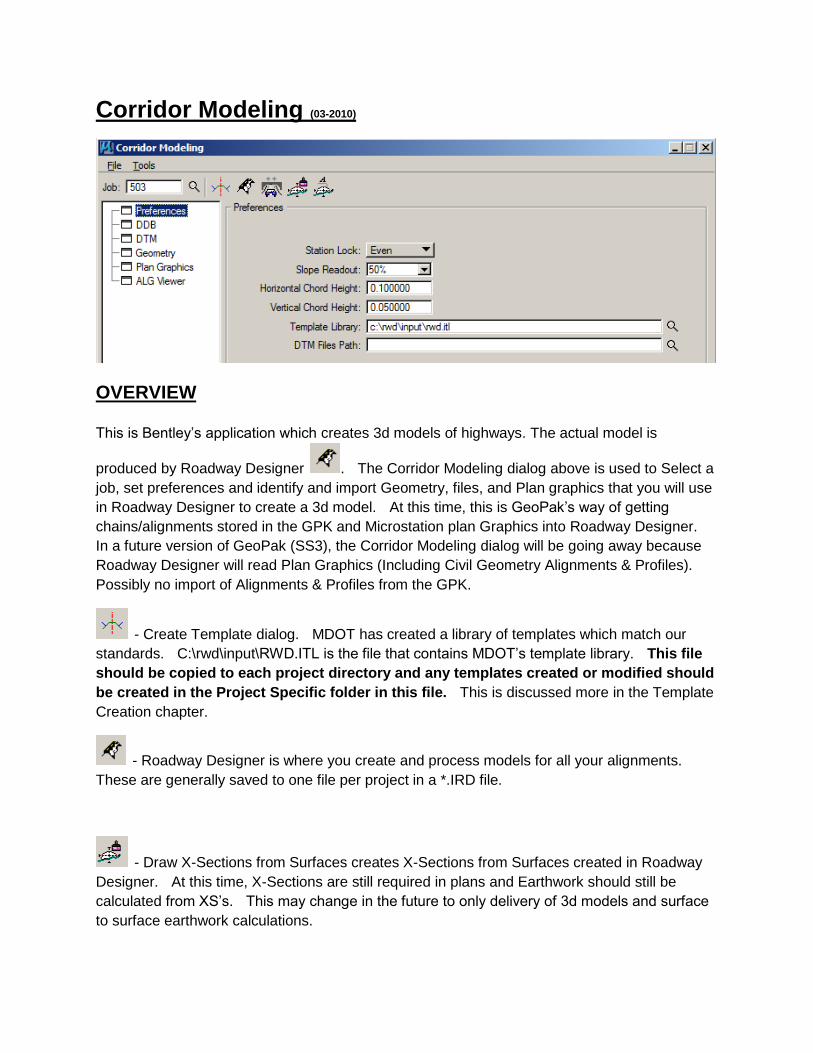
OVERVIEW
This is Bentley’s application which creates 3d models of highways. The actual model is
produced by Roadway Designer . The Corridor Modeling dialog above is used to Select a
job, set preferences and identify and import Geometry, files, and Plan graphics that you will use
in Roadway Designer to create a 3d model. At this time, this is GeoPak’s way of getting
chains/alignments stored in the GPK and Microstation plan Graphics into Roadway Designer.
In a future version of GeoPak (SS3), the Corridor Modeling dialog will be going away because
Roadway Designer will read Plan Graphics (Including Civil Geometry Alignments & Profiles).
Possibly no import of Alignments & Profiles from the GPK.
- Create Template dialog. MDOT has created a library of templates which match our
standards. C:\rwd\input\RWD.ITL is the file that contains MDOT’s template library. This file
should be copied to each project directory and any templates created or modified should
be created in the Project Specific folder in this file. This is discussed more in the Template
Creation chapter.
- Roadway Designer is where you create and process models for all your alignments.
These are generally saved to one file per project in a *.IRD file.
- Draw X-Sections from Surfaces creates X-Sections from Surfaces created in Roadway
Designer. At this time, X-Sections are still required in plans and Earthwork should still be
calculated from XS’s. This may change in the future to only delivery of 3d models and surface
to surface earthwork calculations.
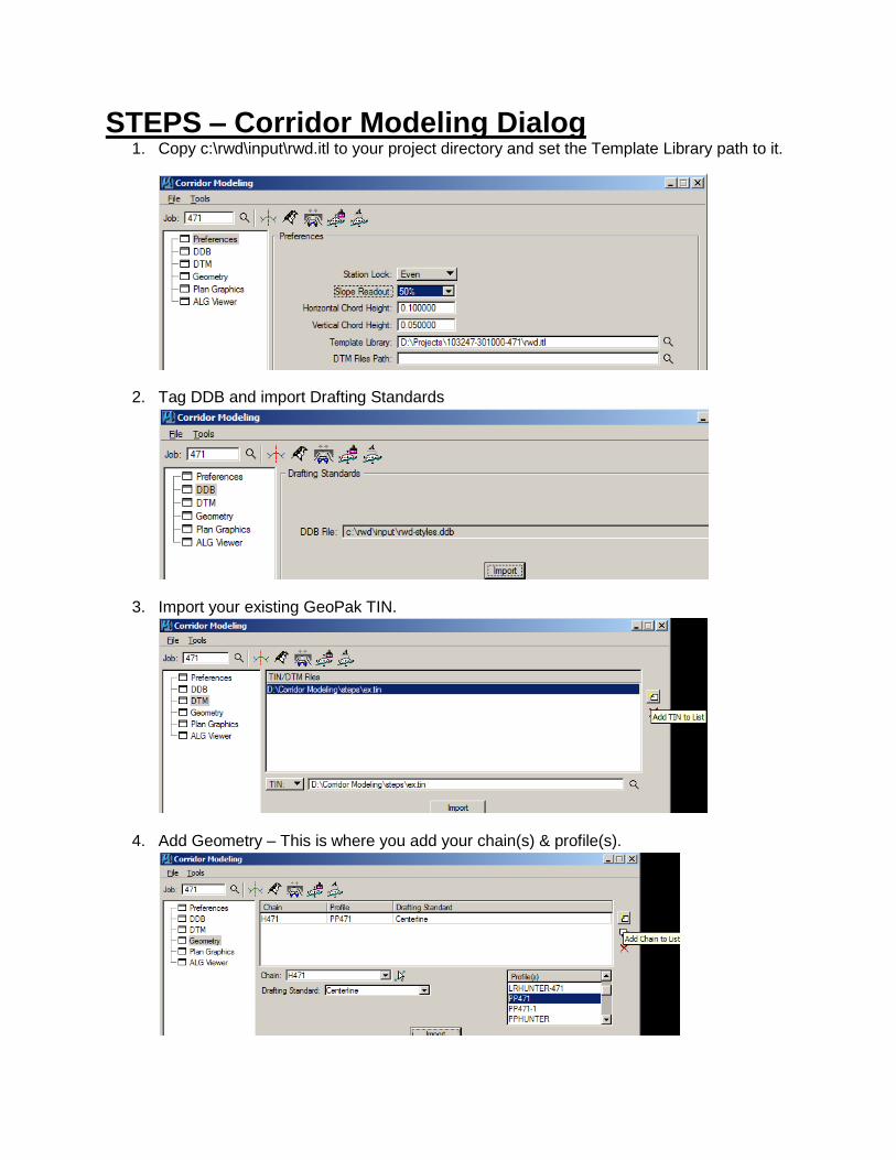
STEPS – Corridor Modeling Dialog 1. Copy c:\rwd\input\rwd.itl to your project directory and set the Template Library path to it.
2. Tag DDB and import Drafting Standards
3. Import your existing GeoPak TIN.
4. Add Geometry – This is where you add your chain(s) & profile(s).
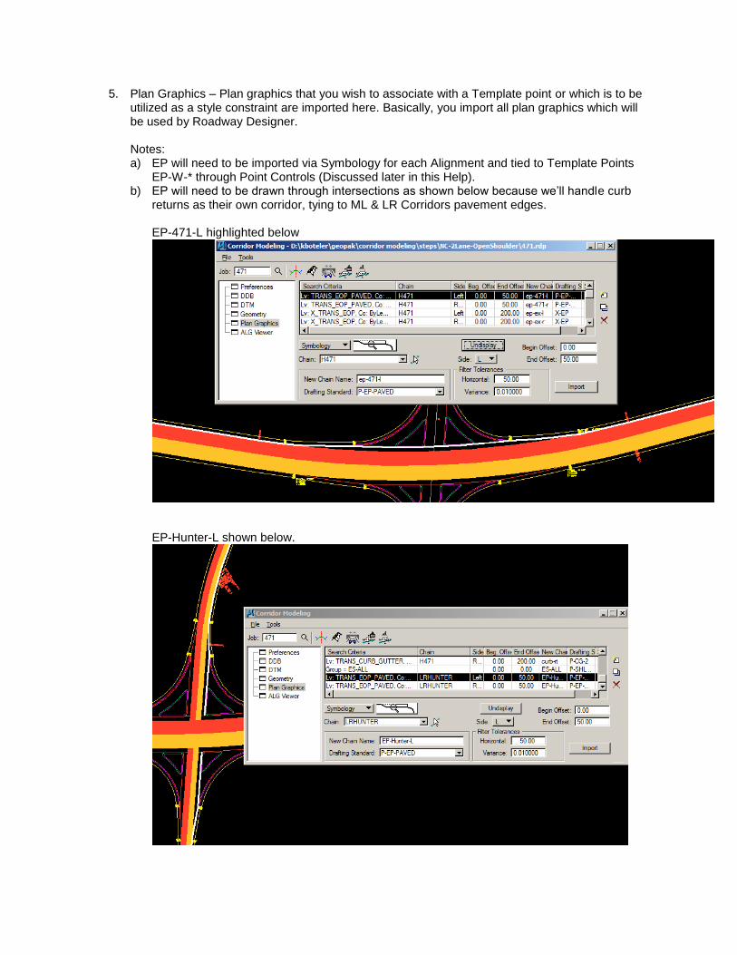
5. Plan Graphics – Plan graphics that you wish to associate with a Template point or which is to be utilized as a style constraint are imported here. Basically, you import all plan graphics which will be used by Roadway Designer. Notes: a) EP will need to be imported via Symbology for each Alignment and tied to Template Points
EP-W-* through Point Controls (Discussed later in this Help). b) EP will need to be drawn through intersections as shown below because we’ll handle curb
returns as their own corridor, tying to ML & LR Corridors pavement edges. EP-471-L highlighted below
EP-Hunter-L shown below.
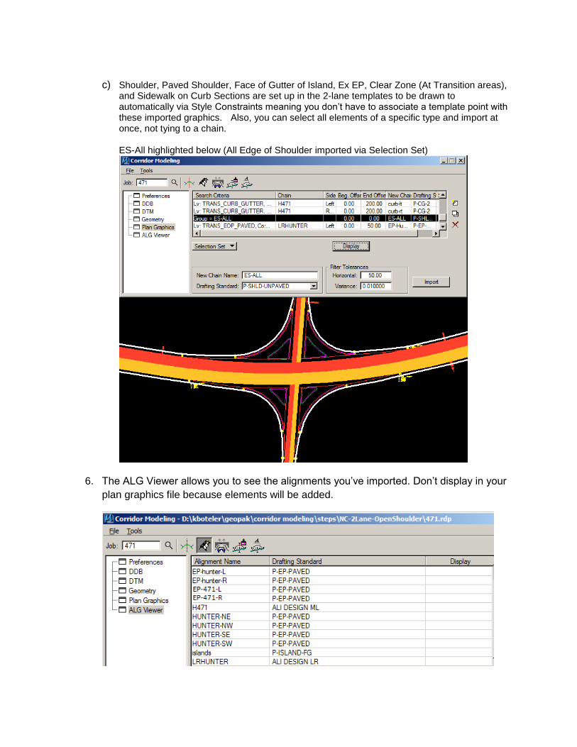
c) Shoulder, Paved Shoulder, Face of Gutter of Island, Ex EP, Clear Zone (At Transition areas), and Sidewalk on Curb Sections are set up in the 2-lane templates to be drawn to automatically via Style Constraints meaning you don’t have to associate a template point with these imported graphics. Also, you can select all elements of a specific type and import at once, not tying to a chain.
ES-All highlighted below (All Edge of Shoulder imported via Selection Set)
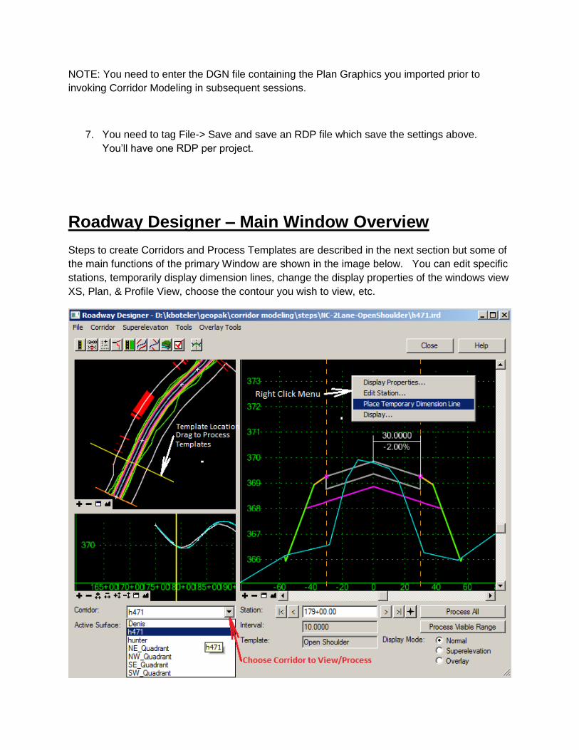
6. The ALG Viewer allows you to see the alignments you’ve imported. Don’t display in your
plan graphics file because elements will be added.
NOTE: You need to enter the DGN file containing the Plan Graphics you imported prior to
invoking Corridor Modeling in subsequent sessions.
7. You need to tag File-> Save and save an RDP file which save the settings above.
You’ll have one RDP per project.
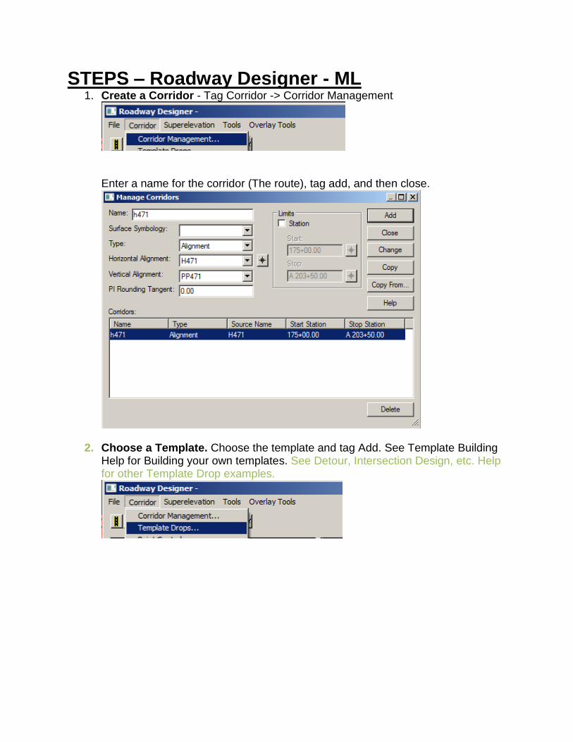
Roadway Designer – Main Window Overview
Steps to create Corridors and Process Templates are described in the next section but some of
the main functions of the primary Window are shown in the image below. You can edit specific
stations, temporarily display dimension lines, change the display properties of the windows view
XS, Plan, & Profile View, choose the contour you wish to view, etc.
STEPS – Roadway Designer - ML 1. Create a Corridor - Tag Corridor -> Corridor Management
Enter a name for the corridor (The route), tag add, and then close.
2. Choose a Template. Choose the template and tag Add. See Template Building Help for Building your own templates. See Detour, Intersection Design, etc. Help for other Template Drop examples.
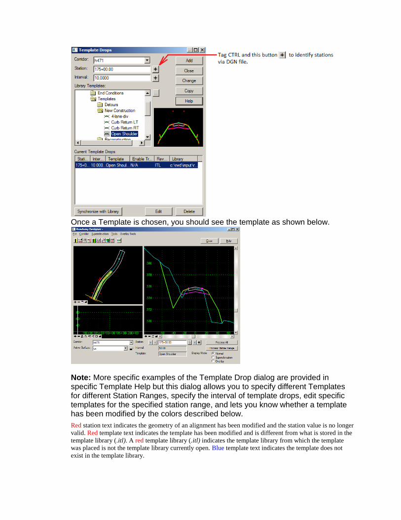
Once a Template is chosen, you should see the template as shown below.
Note: More specific examples of the Template Drop dialog are provided in specific Template Help but this dialog allows you to specify different Templates for different Station Ranges, specify the interval of template drops, edit specific templates for the specified station range, and lets you know whether a template has been modified by the colors described below.
Red station text indicates the geometry of an alignment has been modified and the station value is no longer
valid. Red template text indicates the template has been modified and is different from what is stored in the
template library (.itl). A red template library (.itl) indicates the template library from which the template
was placed is not the template library currently open. Blue template text indicates the template does not
exist in the template library.
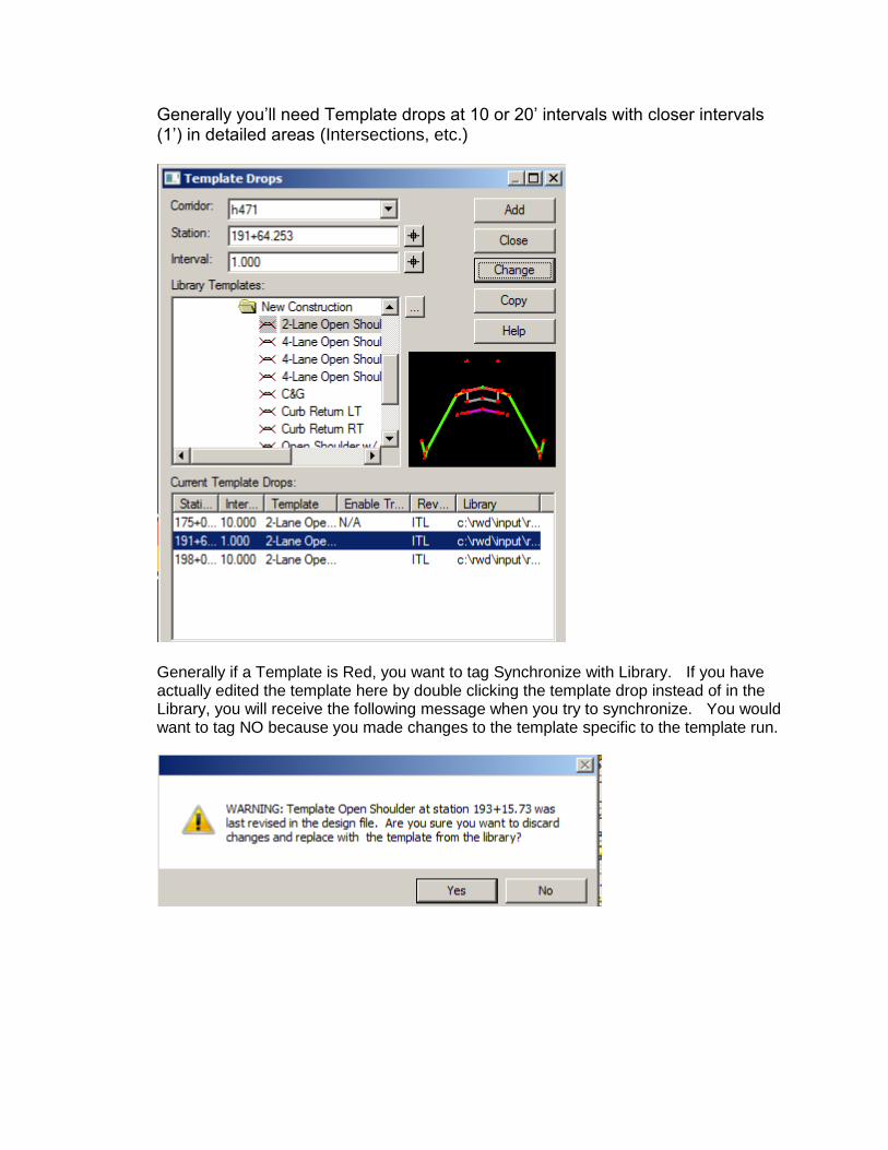
Generally you’ll need Template drops at 10 or 20’ intervals with closer intervals (1’) in detailed areas (Intersections, etc.)
Generally if a Template is Red, you want to tag Synchronize with Library. If you have actually edited the template here by double clicking the template drop instead of in the Library, you will receive the following message when you try to synchronize. You would want to tag NO because you made changes to the template specific to the template run.
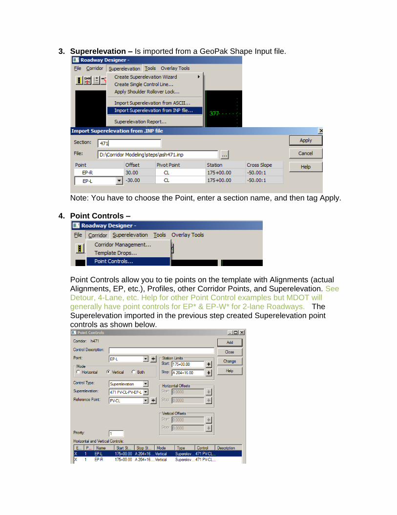
3. Superelevation – Is imported from a GeoPak Shape Input file.
Note: You have to choose the Point, enter a section name, and then tag Apply.
4. Point Controls –
Point Controls allow you to tie points on the template with Alignments (actual Alignments, EP, etc.), Profiles, other Corridor Points, and Superelevation. See Detour, 4-Lane, etc. Help for other Point Control examples but MDOT will generally have point controls for EP* & EP-W* for 2-lane Roadways. The Superelevation imported in the previous step created Superelevation point controls as shown below.
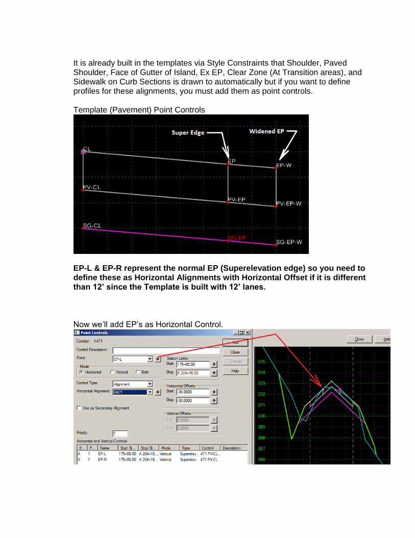
It is already built in the templates via Style Constraints that Shoulder, Paved Shoulder, Face of Gutter of Island, Ex EP, Clear Zone (At Transition areas), and Sidewalk on Curb Sections is drawn to automatically but if you want to define profiles for these alignments, you must add them as point controls. Template (Pavement) Point Controls
EP-L & EP-R represent the normal EP (Superelevation edge) so you need to define these as Horizontal Alignments with Horizontal Offset if it is different than 12’ since the Template is built with 12’ lanes. Now we’ll add EP’s as Horizontal Control.
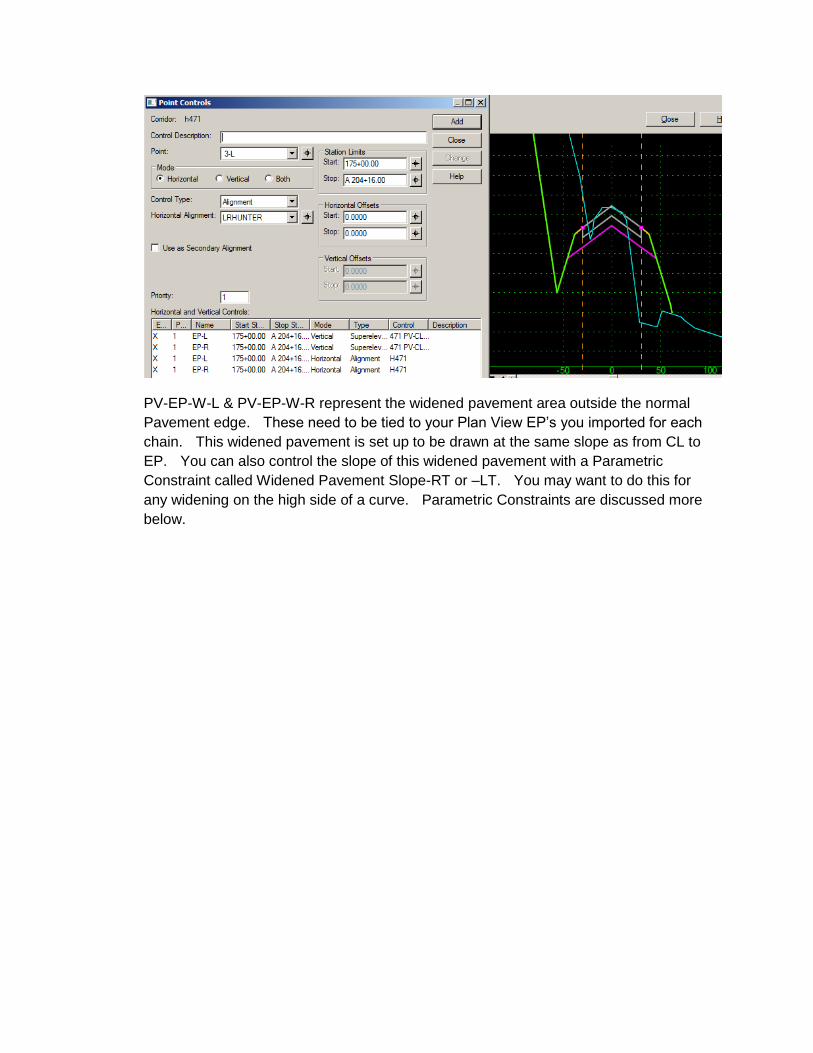
PV-EP-W-L & PV-EP-W-R represent the widened pavement area outside the normal
Pavement edge. These need to be tied to your Plan View EP’s you imported for each
chain. This widened pavement is set up to be drawn at the same slope as from CL to
EP. You can also control the slope of this widened pavement with a Parametric
Constraint called Widened Pavement Slope-RT or –LT. You may want to do this for
any widening on the high side of a curve. Parametric Constraints are discussed more
below.
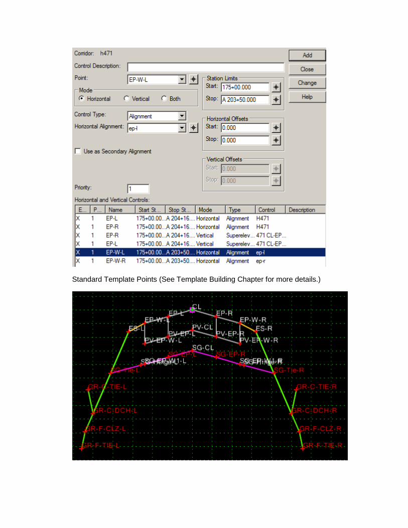
Standard Template Points (See Template Building Chapter for more details.)
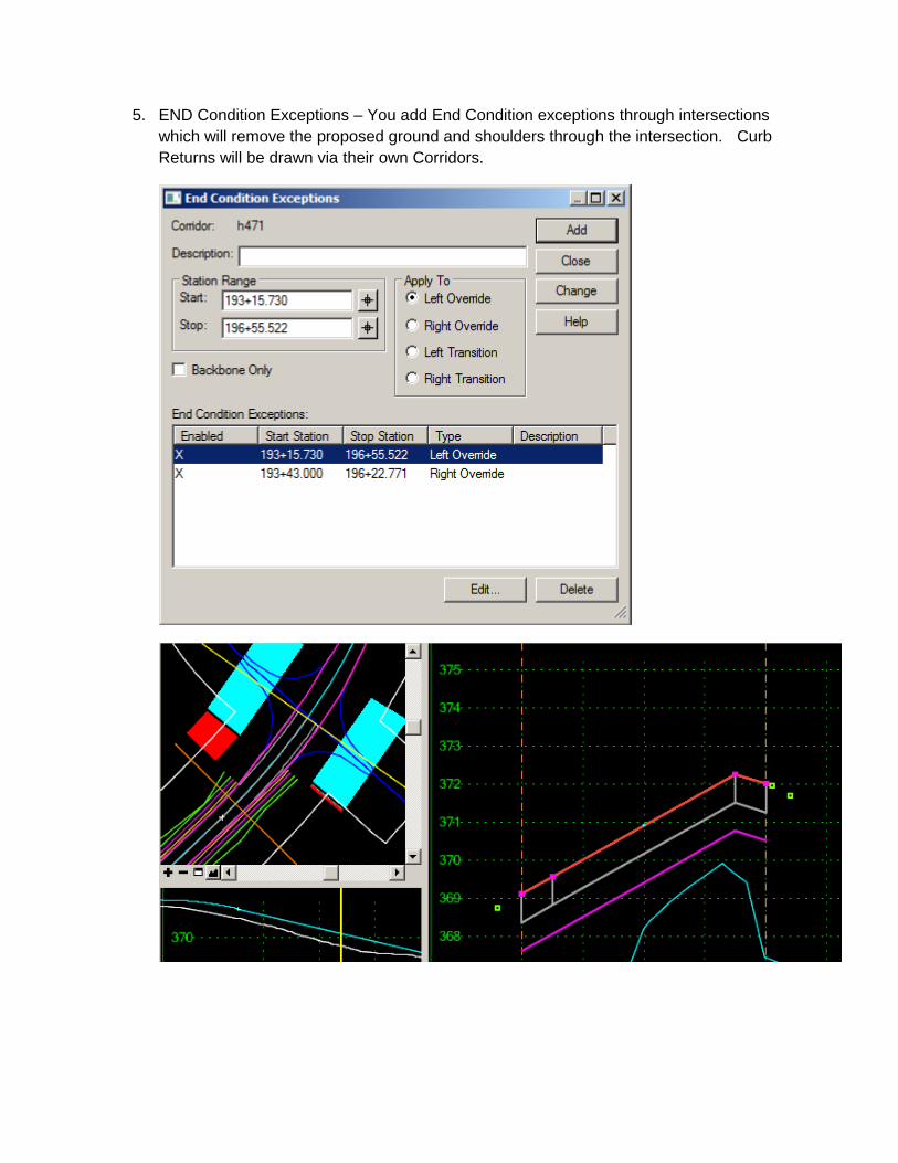
5. END Condition Exceptions – You add End Condition exceptions through intersections
which will remove the proposed ground and shoulders through the intersection. Curb
Returns will be drawn via their own Corridors.
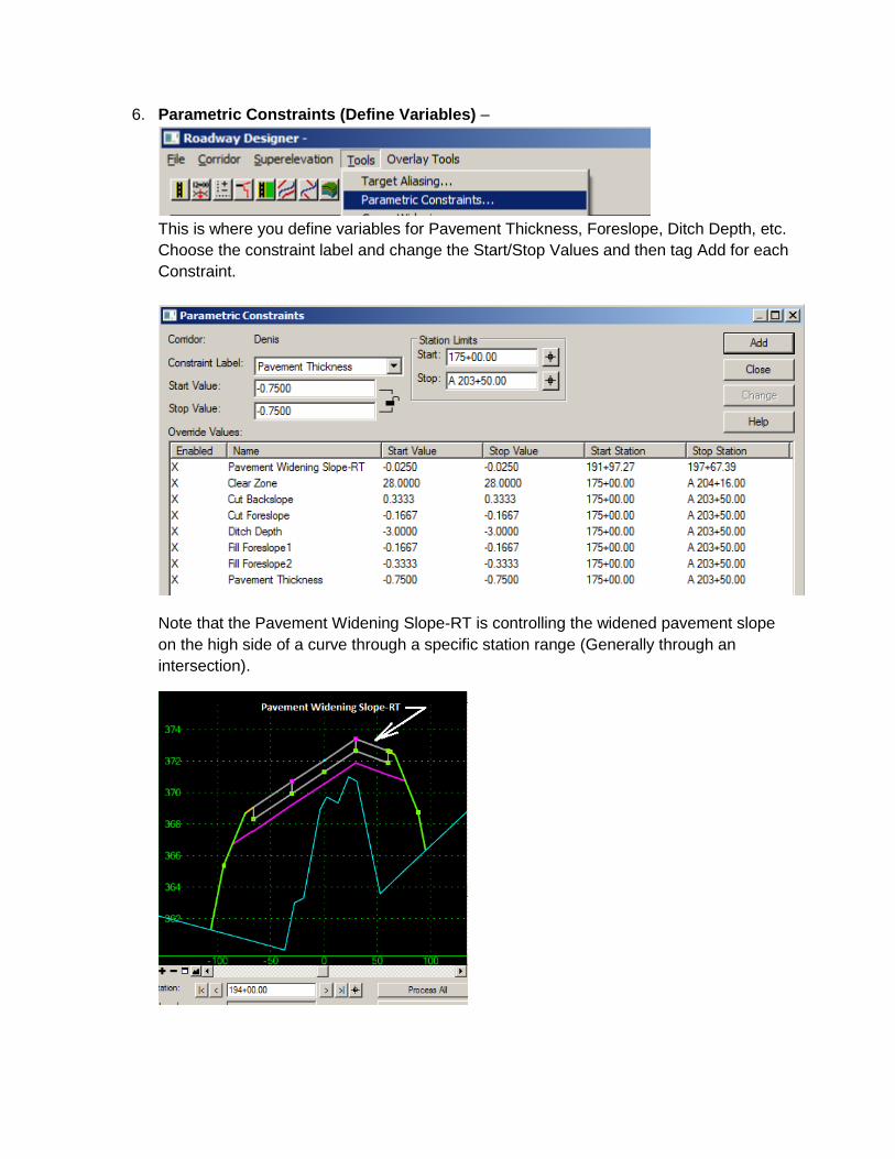
6. Parametric Constraints (Define Variables) –
This is where you define variables for Pavement Thickness, Foreslope, Ditch Depth, etc.
Choose the constraint label and change the Start/Stop Values and then tag Add for each
Constraint.
Note that the Pavement Widening Slope-RT is controlling the widened pavement slope
on the high side of a curve through a specific station range (Generally through an
intersection).
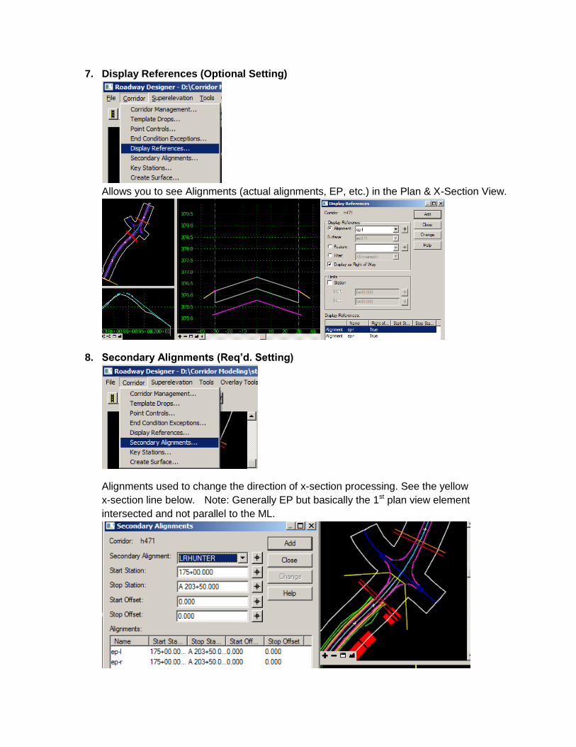
7. Display References (Optional Setting)
Allows you to see Alignments (actual alignments, EP, etc.) in the Plan & X-Section View.
8. Secondary Alignments (Req’d. Setting)
Alignments used to change the direction of x-section processing. See the yellow
x-section line below. Note: Generally EP but basically the 1st plan view element
intersected and not parallel to the ML.
STEPS – Roadway Designer - LR
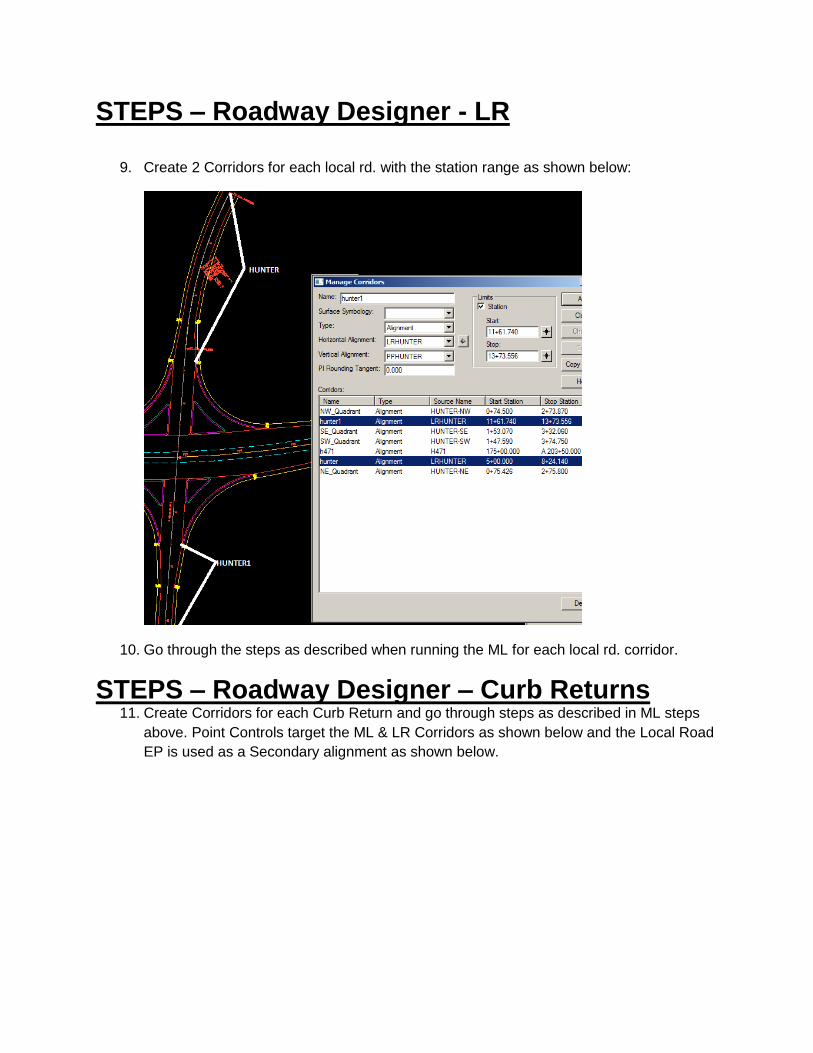
9. Create 2 Corridors for each local rd. with the station range as shown below:
10. Go through the steps as described when running the ML for each local rd. corridor.
STEPS – Roadway Designer – Curb Returns 11. Create Corridors for each Curb Return and go through steps as described in ML steps
above. Point Controls target the ML & LR Corridors as shown below and the Local Road
EP is used as a Secondary alignment as shown below.
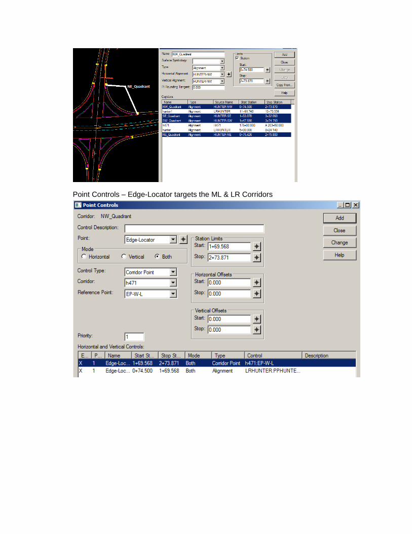
Point Controls – Edge-Locator targets the ML & LR Corridors
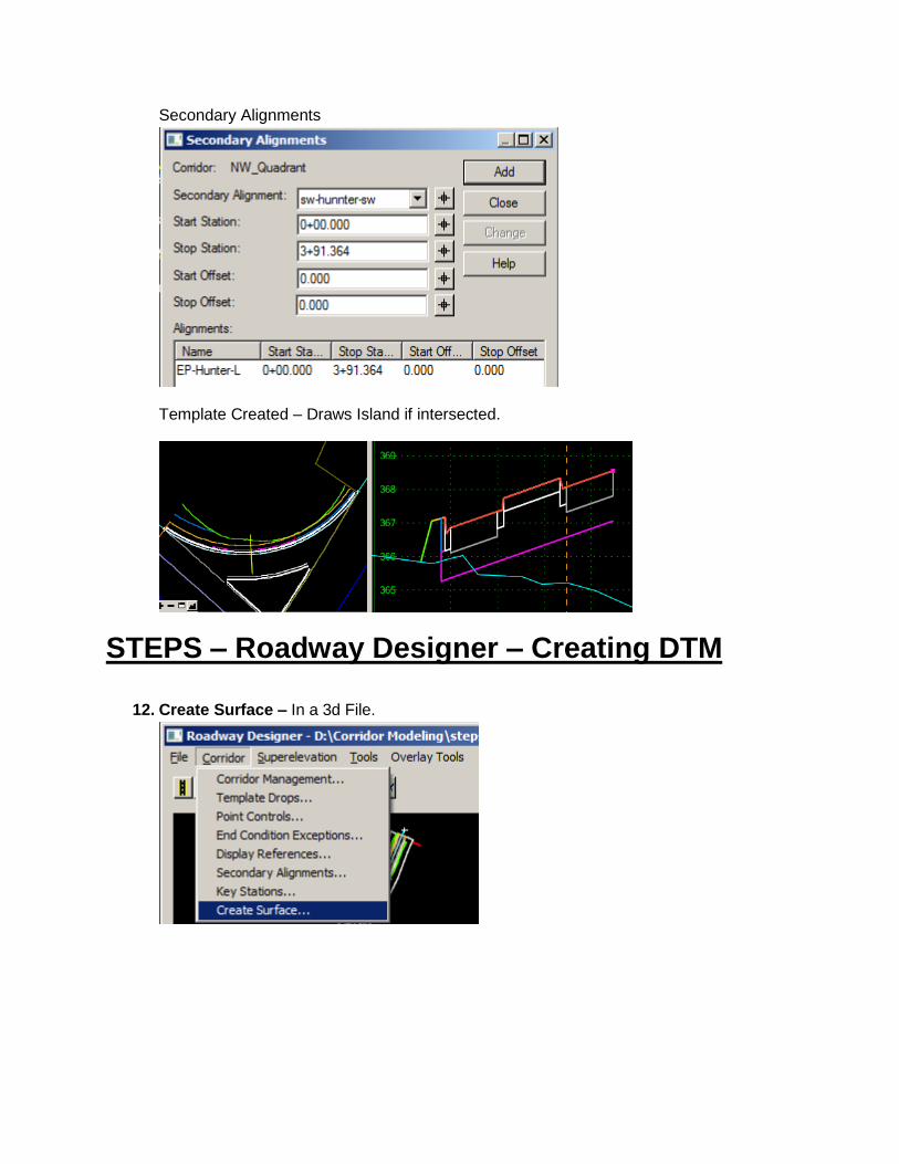
Secondary Alignments
Template Created – Draws Island if intersected.
STEPS – Roadway Designer – Creating DTM
12. Create Surface – In a 3d File.
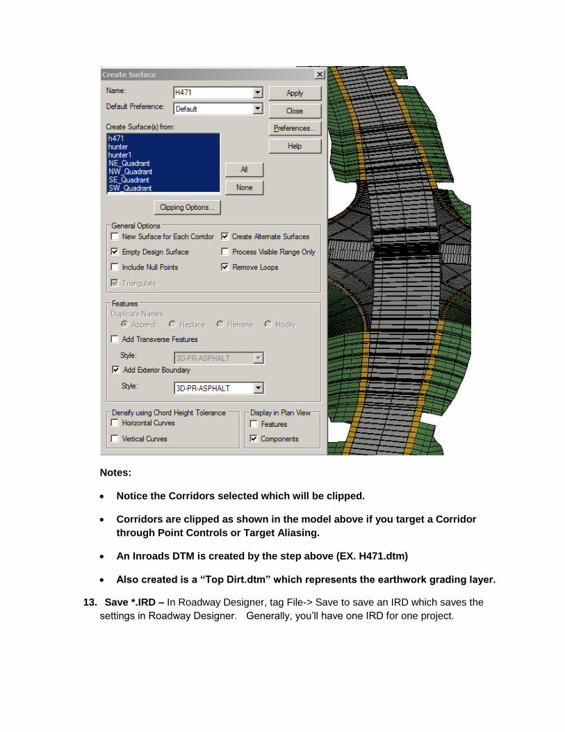
Notes:
Notice the Corridors selected which will be clipped.
Corridors are clipped as shown in the model above if you target a Corridor
through Point Controls or Target Aliasing.
An Inroads DTM is created by the step above (EX. H471.dtm)
Also created is a “Top Dirt.dtm” which represents the earthwork grading layer.
13. Save *.IRD – In Roadway Designer, tag File-> Save to save an IRD which saves the
settings in Roadway Designer. Generally, you’ll have one IRD for one project.
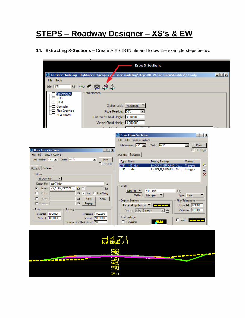
STEPS – Roadway Designer – XS’s & EW
14. Extracting X-Sections – Create A XS DGN file and follow the example steps below.

11) Earthwork – An earthwork file called earthwk-corridor-xs.inp has been created to run
earthwork on XS’s created from DTM surfaces created by Roadway Designer. Tolerance has
been adjusted to handle cases where the proposed ground does not tie to existing ground
exactly because of skewed sections or sections cut where there is no section in Roadway
Designer.