Correlation of pre-earthquake electromagnetic signals · PDF fileCorrelation of pre-earthquake...
11
Nat. Hazards Earth Syst. Sci., 10, 1965–1975, 2010 www.nat-hazards-earth-syst-sci.net/10/1965/2010/ doi:10.5194/nhess-10-1965-2010 © Author(s) 2010. CC Attribution 3.0 License. Natural Hazards and Earth System Sciences Correlation of pre-earthquake electromagnetic signals with laboratory and field rock experiments T. Bleier 1 , C. Dunson 1 , C. Alvarez 1 , F. Freund 2 , and R. Dahlgren 3 1 Quakefinder, Palo Alto, Ca, USA 2 NASA Ames Research Center, Moffett Field, Ca, USA 3 Dept. of Physics and Astronomy, San Jos´ e State University, San Jos´ e, Ca, USA Received: 10 May 2010 – Revised: 20 August 2010 – Accepted: 3 September 2010 – Published: 24 September 2010 Abstract. Analysis of the 2007 M5.4 Alum Rock earth- quake near San Jos´ e California showed that magnetic pul- sations were present in large numbers and with significant amplitudes during the 2 week period leading up the event. These pulsations were 1–30 s in duration, had unusual po- larities (many with only positive or only negative polarities versus both polarities), and were different than other pulsa- tions observed over 2 years of data in that the pulse sequence was sustained over a 2 week period prior to the quake, and then disappeared shortly after the quake. A search for the underlying physics process that might explain these pulses was was undertaken, and one theory (Freund, 2002) demon- strated that charge carriers were released when various types of rocks were stressed in a laboratory environment. It was also significant that the observed charge carrier generation was transient, and resulted in pulsating current patterns. In an attempt to determine if this phenomenon occurred outside of the laboratory environment, the authors scaled up the physics experiment from a relatively small rock sample in a dry lab- oratory setting, to a large 7 metric tonne boulder comprised of Yosemite granite. This boulder was located in a natural, humid (above ground) setting at Bass Lake, Ca. The boul- der was instrumented with two Zonge Engineering, Model ANT4 induction type magnetometers, two Trifield Air Ion Counters, a surface charge detector, a geophone, a Bruker Model EM27 Fourier Transform Infra Red (FTIR) spectrom- eter with Sterling cycle cooler, and various temperature sen- sors. The boulder was stressed over about 8 h using expand- ing concrete (Bustar tm ), until it fractured into three major pieces. The recorded data showed surface charge build up, magnetic pulsations, impulsive air conductivity changes, and acoustical cues starting about 5 h before the boulder actually Correspondence to: T. Bleier ([email protected]) broke. These magnetic and air conductivity pulse signatures resembled both the laboratory rock stressing results and the 30 October 2007 M5.4 Alum Rock earthquake field data. The second part of this paper examined other California earthquakes, prior to the Alum Rock earthquake, to see if magnetic pulsations were also present prior to those events. A search for field examples of medium earthquakes was performed to identify earthquakes where functioning mag- netometers were present within 20 km, the expected detec- tion range of the magnetometers. Two earthquakes identi- fied in the search included the 12 August 1998 M5.1 San Juan Bautista (Hollister Ca.) earthquake and the 28 Septem- ber 2004 M6.0 Parkfield Ca. earthquake. Both of these data sets were recorded using EMI Corp. Model BF4 induction magnetometers, installed in equipment owned and operated by UC Berkeley. Unfortunately, no air conductivity or IR data were available for these earthquake examples. This new analysis of old data used the raw time series data (40 samples per s), and examined the data for short duration pulsations that exceeded the normal background noise levels at each site, similar to the technique used at Alum Rock. Analy- sis of Hollister magnetometer, positioned 2 km from the epi- center, showed a significant increase in magnetic pulsations above quiescient threshold levels several weeks prior, and es- pecially 2 days prior to the quake. The pattern of positive and negative pulsations observed at Hollister, were similar, but not identical to Alum Rock in that the pattern of pulsa- tions were interspersed with Pc 1 pulsation trains, and did not start 2 weeks prior to the quake, but rather 2 days prior. The Parkfield data (magnetometer positioned 19 km from the epi- center) showed much smaller pre-earthquake pulsations, but the area had significantly higher conductivity (which atten- uates the signals). More interesting was the fact that signif- icant pulsations occurred between the aftershock sequences of quakes as the crustal stress patterns were migrating. Published by Copernicus Publications on behalf of the European Geosciences Union.
-
Upload
nguyenkhuong -
Category
Documents
-
view
217 -
download
3
Transcript of Correlation of pre-earthquake electromagnetic signals · PDF fileCorrelation of pre-earthquake...

Nat. Hazards Earth Syst. Sci., 10, 1965–1975, 2010www.nat-hazards-earth-syst-sci.net/10/1965/2010/doi:10.5194/nhess-10-1965-2010© Author(s) 2010. CC Attribution 3.0 License.
Natural Hazardsand Earth
System Sciences
Correlation of pre-earthquake electromagnetic signalswith laboratory and field rock experiments
T. Bleier1, C. Dunson1, C. Alvarez1, F. Freund2, and R. Dahlgren3
1Quakefinder, Palo Alto, Ca, USA2NASA Ames Research Center, Moffett Field, Ca, USA3Dept. of Physics and Astronomy, San Jose State University, San Jose, Ca, USA
Received: 10 May 2010 – Revised: 20 August 2010 – Accepted: 3 September 2010 – Published: 24 September 2010
Abstract. Analysis of the 2007M5.4 Alum Rock earth-quake near San Jose California showed that magnetic pul-sations were present in large numbers and with significantamplitudes during the 2 week period leading up the event.These pulsations were 1–30 s in duration, had unusual po-larities (many with only positive or only negative polaritiesversus both polarities), and were different than other pulsa-tions observed over 2 years of data in that the pulse sequencewas sustained over a 2 week period prior to the quake, andthen disappeared shortly after the quake. A search for theunderlying physics process that might explain these pulseswas was undertaken, and one theory (Freund, 2002) demon-strated that charge carriers were released when various typesof rocks were stressed in a laboratory environment. It wasalso significant that the observed charge carrier generationwas transient, and resulted in pulsating current patterns. In anattempt to determine if this phenomenon occurred outside ofthe laboratory environment, the authors scaled up the physicsexperiment from a relatively small rock sample in a dry lab-oratory setting, to a large 7 metric tonne boulder comprisedof Yosemite granite. This boulder was located in a natural,humid (above ground) setting at Bass Lake, Ca. The boul-der was instrumented with two Zonge Engineering, ModelANT4 induction type magnetometers, two Trifield Air IonCounters, a surface charge detector, a geophone, a BrukerModel EM27 Fourier Transform Infra Red (FTIR) spectrom-eter with Sterling cycle cooler, and various temperature sen-sors. The boulder was stressed over about 8 h using expand-ing concrete (Bustartm), until it fractured into three majorpieces. The recorded data showed surface charge build up,magnetic pulsations, impulsive air conductivity changes, andacoustical cues starting about 5 h before the boulder actually
Correspondence to:T. Bleier([email protected])
broke. These magnetic and air conductivity pulse signaturesresembled both the laboratory rock stressing results and the30 October 2007M5.4 Alum Rock earthquake field data.
The second part of this paper examined other Californiaearthquakes, prior to the Alum Rock earthquake, to see ifmagnetic pulsations were also present prior to those events.A search for field examples of medium earthquakes wasperformed to identify earthquakes where functioning mag-netometers were present within 20 km, the expected detec-tion range of the magnetometers. Two earthquakes identi-fied in the search included the 12 August 1998M5.1 SanJuan Bautista (Hollister Ca.) earthquake and the 28 Septem-ber 2004M6.0 Parkfield Ca. earthquake. Both of these datasets were recorded using EMI Corp. Model BF4 inductionmagnetometers, installed in equipment owned and operatedby UC Berkeley. Unfortunately, no air conductivity or IRdata were available for these earthquake examples. This newanalysis of old data used the raw time series data (40 samplesper s), and examined the data for short duration pulsationsthat exceeded the normal background noise levels at eachsite, similar to the technique used at Alum Rock. Analy-sis of Hollister magnetometer, positioned 2 km from the epi-center, showed a significant increase in magnetic pulsationsabove quiescient threshold levels several weeks prior, and es-pecially 2 days prior to the quake. The pattern of positiveand negative pulsations observed at Hollister, were similar,but not identical to Alum Rock in that the pattern of pulsa-tions were interspersed with Pc 1 pulsation trains, and did notstart 2 weeks prior to the quake, but rather 2 days prior. TheParkfield data (magnetometer positioned 19 km from the epi-center) showed much smaller pre-earthquake pulsations, butthe area had significantly higher conductivity (which atten-uates the signals). More interesting was the fact that signif-icant pulsations occurred between the aftershock sequencesof quakes as the crustal stress patterns were migrating.
Published by Copernicus Publications on behalf of the European Geosciences Union.

1966 T. Bleier et al.: Correlation of EM data with lab/field experiments
Comparing laboratory, field experiments with a boulder,and earthquake events, striking similarities were noted inmagnetic pulsations and air conductivity changes, as well asIR signals (where instrumented). More earthquake samples,taken with the appropriate detectors and within 10–15 kmproximity to large (> M5) earthquakes, are still needed toprovide more evidence to understand the variability betweenearthquakes and various electromagnetic signals detectedprior to large earthquakes.
1 Introduction
A number of papers have reported various electromagneticsignals being detected prior to large earthquakes. These in-clude theM7.0 Loma Prieta, Ca. quake in 1989 (Fraser-Smith, 1990, 1991), Izu Islands earthquake swarm, Japan(Hattori, 2004), and theM5.4 Alum Rock, Ca. quake in 2007(Bleier, 2009). In addition, work has evolved trying to ex-plain the underlying physics involved with these electromag-netic signals. Two theories have been cited recently. Thefirst is based on the release of Radon gas prior to the earth-quake, which may then cause air conductivity changes, la-tent heat/IR signatures, and ionospheric changes (Liu, 2004;Ouzounov, 2007). The second theory is based on semicon-ductor physics, and cites the existence of stress-induced mo-bile charge carriers (p-holes) in the rock structure that causeactive current pulses within rocks, corresponding magneticpulsations, air conductivity changes near the ground, InfraRed (IR) signatures within a wider area, and Total ElectronContent (TEC) changes in the ionosphere above the epicenter(Freund, 2006, 2007).
There were no radon detector data sets that could be foundto try to correlate with California earthquakes.
The first objective of this paper was to devise an experi-ment that could test the semi-conductor theory under more“normal” outside conditions rather than temperature and hu-midity within controlled laboratory experiments. Based onthe initial results from the laboratory experiments by Freund,we decided to “scale up” the experiment and determine ifthese same semiconductor effects could be detected withmuch larger samples, located in a natural setting, with naturalhumidity and temperature conditions of a field location. Theauthors had access to a large 7 metric tonne boulder, com-posed of Yosemite granite, at a construction site near BassLake, Ca. The authors collaborated to instrument the boul-der with magnetometers, air conductivity and surface chargedetectors, and a Sterling-cycle cooled IR spectrometer. The2 m by 1.5 m by 1.5 m boulder was located on a hillside, inthe open, and thus subject to local humidity and tempera-ture variations throughout the day and night. This experi-ment will be described in sections 2–3 of this paper. Theinfra red (IR) energy detected from the boulder while understress will be addressed in future paper by Freund. This data
was then compared against similar signals (magnetic pulsesand IR) detected at the 30 October 2007M5.4 Alum Rockearthquake event.
The second objective of this paper was to re-examine sev-eral archived earthquake events that were fortuitously locatednear magnetometers and had raw time series data over sev-eral years that could be examined for magnetic pulsations.Two earthquake data sets were identified, one for the 12 Au-gust 1998 San Juan BautistaM5.1 earthquake near HollisterCalifornia (Berkeley SAO magnetometer data set for 1997–1998), and one for the 28 September 2004 Parkfield, Ca.M6.0 quake (Berkeley PKD magnetometer data set from2003–2004). Section 4 of this paper describes this analysis.
The theory of charge carriers (Freund, 2006, 2007) wouldpredict that both the boulder experiment and the 2 addi-tional earthquake data sets should indicate magnetic pulsa-tions recorded in the local magnetometer instruments, andthe signatures (pulse shapes and polarities) should be simi-lar. This above ground boulder was a first step in examiningin situ rock responses to stress. In the future, an additionalrock stressing experiment is being proposed for an area sev-eral thousand feet below the ground at the Deep UndergroundScience Experiment Laboratory (DUSEL), located at the for-mer Homestake gold mine in Lead, North Dakota. There, thestress levels, heat, moisture, and boundary conditions may beeven closer to actual earthquake hypocenter conditions.
2 Boulder experiment
In multiple laboratory rock stressing experiments (Freund,2006), there was evidence of pulsating currents occurring asdetected with nano-ammeters. Figure 1 illustrates the currentsignatures that were observed when granite was compressed.
Figure 2 shows a 7 metric tonne boulder, comprised ofYosemite granite, and located at 37.294301◦ N Latitude and−119.520182◦ W Longitude near Bass Lake, Ca.
The boulder was prepared by drilling an array of four 5 cmdiameter by 1.1 m blind holes pattern, along the centerline ofthe boulder, and subsequently left to dry and redistribute thestress over a 3 week quiet period. This is shown in Fig. 3.
The boulder was then instrumented using two Zonge Eng.Model ANT4 induction type magnetometers, two Trifield AirIon Counters, a “capacitor-type” surface charge detector (ap-prox. 30 cm square copper sheet and an interstitial mylar in-sulator sheet, a 4 Hz geophone, a Bruker Model EM27 IRspectrometer with Sterling-cycle cooler, and 3 temperaturesensors (one mounted in the center hole, one mounted on theEast face, and one mounted on the West face of the boulder).Figure 4 illustrates the approximate layout of the sensors.
During the boulder experiment, the Air Ion Detectors wereset to a maximum of 1999×106 ions per cc per sec flow rate.One meter was set to negative polarity (and worked well),and the other was set to center position (which at the time wethought was “both” polarities, but actually did not register
Nat. Hazards Earth Syst. Sci., 10, 1965–1975, 2010 www.nat-hazards-earth-syst-sci.net/10/1965/2010/

T. Bleier et al.: Correlation of EM data with lab/field experiments 1967
16
7 1
2
Figure 1 Current profile of stressed Gabbro rock (Freund) 3
4
5
Figure 2 Yosemite granite 7 metric ton boulder , Freund (left) and Bleier (right) 6
7
8
9
10
Fig. 1. Current profile of stressed Gabbro rock (Freund, 2006).
16
7 1
2
Figure 1 Current profile of stressed Gabbro rock (Freund) 3
4
5
Figure 2 Yosemite granite 7 metric ton boulder , Freund (left) and Bleier (right) 6
7
8
9
10
Fig. 2. Yosemite granite 7 metric tonne boulder, Freund (left) andBleier (right).
either polarity). The two Trifield Air Ion detectors were lo-cated near the top of the boulder, suspended approximately20 cm above the north and southern portion of the boulder.The magnetometers were located on the ground, in shallowtrenches, approximately 1 m north and 1 m to the south of theboulder, with the axis of the magnetometer pointed towardthe base of the boulder. Two temperature sensors were lo-cated on the East and West faces of the boulder respectively,while one sensor was lowered into a central bore hole, to adepth of approximately tcenter of the rock. Note this sensorfunctioned temporarily until the expanding concrete crushedthe sensor, and from then forward, the center temperaturedata was unusable.
17
1
Figure 3 Top view of the boulder illustrating the 4 vertical hole pattern before filling 2
3
4
Figure 4 A notional view of the boulder and instrument layout, North is left, and South is 5
right. 6
7
Fig. 3. Top view of the boulder illustrating the 4 vertical hole patternbefore filling.
17
1
Figure 3 Top view of the boulder illustrating the 4 vertical hole pattern before filling 2
3
4
Figure 4 A notional view of the boulder and instrument layout, North is left, and South is 5
right. 6
7
Fig. 4. A schematic view of the boulder and instrument layout,North is left, and South is right.
The expanding cement (BustarTM) was added at 10 p.m. atnight and allowed to cure, continuously expanding until theboulder fractured around 05:30 a.m. the following morningas shown in Figs. 5 and 6.
The boulder started to become electrically active around2 h into the test at approximately midnight, and simultane-ously, the magnetometer, air conductivity, surface chargesensor, and geophone all showed active signals.
Figure 6 shows the various signatures around midnight.A negative power supply failed around 2 a.m. affecting theoperational amplifier circuits, but the main signals were
www.nat-hazards-earth-syst-sci.net/10/1965/2010/ Nat. Hazards Earth Syst. Sci., 10, 1965–1975, 2010

1968 T. Bleier et al.: Correlation of EM data with lab/field experiments
18
1
Figure 5 The boulder shown split into 3 major pieces along the plane defined by the hole 2
pattern 3
4
5
6
Figure 6 Experiment timeline on Aug 20-21, 2009 (magnetometer readings) 7
Fig. 5. The boulder shown split into 3 major pieces along the planedefined by the hole pattern.
recorded before that time. The activity on the magnetometerchannels at the times of the instrument setup and the pouringof the expanding cement were due to the team walking pastthe magnetometers with cellphones and metal tools. Oncethe team vacated the area, the magnetometer signals revertedto the normal background signals. Unusual signals startedjust before the midnight calibration signal, and went quietafterward until the magnetometer channels became inopera-tive when the power supply failed at 2 a.m.
Figure 7 shows the magnetic pulses and their durations.The sinusoidal wave on the right of the time span is the startof the 5 min long, 0.8 Hz calibration signal sent to the mag-netometers every midnight. The 3 pulses (widths) are longerthan lightning, typically 0.1 to 0.5 s, and coincident with theother EM signals detected when the boulder started to me-chanically fail.
Figure 8 illustrates the geophone vibrations, also detectednear midnight. The magnetometer calibration sine wavepacket is also detected as crosstalk in the geophone signalwiring, but also serves as a time reference. There appears tobe two mechanical/vibration events for each magnetic pulse.
Figure 9 illustrates the positive and negative ion pulsationsdetected, near midnight.
These large concentrations of ions are unusual in that thereare periods of predominately positive ions and other periodsof predominantly negative ions. The pulse periods are short,and the pulsations stopped around 4 min after midnight.
Figure 10 below shows the surface charges detected withan improvised “capacitor” type charge detector and a volt-meter during the stressing period. Until midnight, the chargeconcentration appears to be positive. Then at midnight,something changes and the net charge changes to negativeuntil the boulder ruptures at 05:30 PST (06:30 PDT).
18
1
Figure 5 The boulder shown split into 3 major pieces along the plane defined by the hole 2
pattern 3
4
5
6
Figure 6 Experiment timeline on Aug 20-21, 2009 (magnetometer readings) 7
Fig. 6. Experiment timeline on 20–21 August 2009.
3 Comparison of rock experiments with Alum Rockearthquake field data
3.1 Comparison of magnetic pulses
Figure 11 illustrates the types of pulses observed during theboulder experiment (bottom panel), and sample prior to the2007 Alum RockM5.4 earthquake (top panel). The bottompanel represents a single pulsation, while the Alum Rock sig-nature is a series of single pulsations, merging into a strongcluster that persists for almost 150 s. Many of the individualpulses in Alum Rock data are similar in duration to the singlepulse in the boulder example.
An inspection of the data was used to set a minimumthreshold for detecting and counting these pulsations in or-der to not count normal background noise.
A pulse duration threshold was set to ignore all pulsesshorter than 1 s. to eliminate power line switching noiseand occasional lightning strikes (those that could be detectedcloser than 150 km). The next pulse threshold was an ampli-tude level threshold that was selected to eliminate vehicularand other man-made noise in the local area. Using such anamplitude threshold (red dotted lines) representing twice (2x)the peak local man-made noise measured at that site loca-tion, any pulses larger than the threshold were counted eachday and stored. Coordination with the site’s landowner, in-spection of the pulse activity, and correlation with the co-located geophone instrument allowed the man-made noiseto be identified (e.g. construction activity and farm imple-ment movements.) When the known human noise periodswere identified, the contaminated noise periods were maskedfrom the pulse files so the long term pulse activity wouldnot be contaminated. Figure 12 illustrates this process, andalso shows the nature of some of the non-man made pulseactivity. “BART” in Fig. 12 refers to Bay Area Rapid Tran-sit trains that generate ULF noise which can contaminate thesignal.
Nat. Hazards Earth Syst. Sci., 10, 1965–1975, 2010 www.nat-hazards-earth-syst-sci.net/10/1965/2010/

T. Bleier et al.: Correlation of EM data with lab/field experiments 1969
19
1
Figure 7 Magnetic pulsations detected near midnight 2
3
4
Figure 8 Output of the geophone, imbedded near the south face of the boulder 5
6
7
Fig. 7. Magnetic pulsations detected near midnight.
19
1
Figure 7 Magnetic pulsations detected near midnight 2
3
4
Figure 8 Output of the geophone, imbedded near the south face of the boulder 5
6
7
Fig. 8. Output of the geophone, embedded near the south face of the boulder.
20
1
2
3
Figure 9 the simultaneous (midnight) surge of positive and negative ion concentrations in 4
the air 20 cm above the boulder 5
6
7
Figure 10 Surface Charge variations throughout the boulder stressing experiment 8
Fig. 9. The simultaneous (midnight) surge of positive and negative ion concentrations in the air 20 cm above the boulder.
www.nat-hazards-earth-syst-sci.net/10/1965/2010/ Nat. Hazards Earth Syst. Sci., 10, 1965–1975, 2010

1970 T. Bleier et al.: Correlation of EM data with lab/field experiments
20
1
2
3
Figure 9 the simultaneous (midnight) surge of positive and negative ion concentrations in 4
the air 20 cm above the boulder 5
6
7
Figure 10 Surface Charge variations throughout the boulder stressing experiment 8 Fig. 10. Surface charge variations throughout the boulder stressing experiment.
21
1
Figure 11 Alum Rock magnetic pulsations (Top) and Boulder magnetic pulsations (Bottom) 2
3
4
Figure 12 Threshold amplitude limits, with positive and negative pulse examples 5
Fig. 11. Alum Rock magnetic pulsations (top) and boulder magnetic pulsations (bottom).
21
1
Figure 11 Alum Rock magnetic pulsations (Top) and Boulder magnetic pulsations (Bottom) 2
3
4
Figure 12 Threshold amplitude limits, with positive and negative pulse examples 5 Fig. 12. Threshold amplitude limits, with positive and negative pulse examples.
Nat. Hazards Earth Syst. Sci., 10, 1965–1975, 2010 www.nat-hazards-earth-syst-sci.net/10/1965/2010/

T. Bleier et al.: Correlation of EM data with lab/field experiments 1971
22
1
Figure 13 Two year pulse count activity for East Milpitas 3
4
5
6
7
Fig. 13. Two year pulse count activity for East Milpitas.
23
1
Figure 14 Alum Rock ionization history for October, 2007 2
3
4
5
6
Fig. 14. Alum Rock ionization history for October 2007.
The result of counting these pulses at East Milpitas (2 kmfrom the earthquake) is shown in Fig. 13: the pulse historyshows that the fault had multiple periods of activity (highpulse counts), but that most of the periods were short (1–3 days). The discriminator prior to the quake was that thepulse activity continued for almost 14 days before the faultactivity “avalanched” into an earthquake event.
3.2 Comparison of air conductivity
The air conductivity in the lab was difficult to measure due tothe small sample size and shielding components. There wereIR emissions, so it is plausible that there was air ionization.
Taking measurements near the boulder in the field wasstraight forward. Two digital Air Ion detectors were installednear the sample. The negative ion meter’s data is shown inFig. 9.
Figure 14 Air Ion particle concentrations measured from20 cm above the boulder.
During the boulder experiment, the weather was warm anddry with no thunderstorm activity within hundreds of kilo-meters of the test site. Weather conditions from 20:00 PDT20 August to 05:30 21 August were 20.3◦C to 16.0◦C withthe barometric pressure at 757 mm Hg (28.9′′ Hg) and slowlyrising. There were no fog, clouds, or thunderstorm activitypresent that could contaminate the test. The air ion activ-ity was negligable before and immediately after the instru-ment setup and into the stressing period. When ion signalssuddenly started occuring near midnight, the ion signaturescould not be explained by any local activity (natural or hu-man) other than the rock stressing activity.
www.nat-hazards-earth-syst-sci.net/10/1965/2010/ Nat. Hazards Earth Syst. Sci., 10, 1965–1975, 2010

1972 T. Bleier et al.: Correlation of EM data with lab/field experiments
24
1
Figure 15 Comparison of 3 independent electromagnetic indicators prior to the Alum Rock 2
earthquake 3
4
Figure 16 Magnetic time series (24 hr each panel) taken at various time prior to the M5.1 5
event 6
Fig. 15. Comparison of 3 independent electromagnetic indicatorsprior to the Alum Rock earthquake.
Next, we compared this test with an actual earthquake dataset. The Alum Rock field ionization data for a one monthperiod prior to the earthquake is shown in Fig. 14 above. Thespacing of the pulses in Fig. 14 on the right side start to getclose together, and on a larger time scale, could be seen toappear as a single saturated signal.
Figure 14 shows both individual conductivity pulsations(sharp spikes) as well as periods of totally saturated readings.The red “X” delineates contaminated data due to rain (highhumidity) causing vapor condensation on the sensor platesand resulting in false signal current.
All these EM indicators (magnetic pulses and air conduc-tivity, as well as IR observed over earthquake areas, namely,the night time IR temperature slope as detected by the GOESweather satellite using its IR camera) are influenced by noisein the data (e.g. noise such as lightning in magnetic data, highhumidity in air conductivity data, and clouds in the IR data).One way to reduce the effect of individual noise contributorsis to observe all three EM indicators over the same area andtime to see if they occur simultaneously.
Figure 15 illustrates the combined pattern of the pulses,IR and air conductivity, normalized to their highest readings(where the ratio = 1.0 for the highest reading for that indica-tor).
In Figure 15, we sought to determine if there were corre-lations among 3 indicators: magnetic pulse counts, air con-ductivity, and Infra Red. The fact that they all appeared topeak at the same times (14 days prior to the quake and theday just prior to the quake, is interesting and may allude tosome combined effect from the existence of the charged par-ticles generated in the sub-surface area near the earthquake.Other indicators could be added to increase the robustnessand confidence levels of this correlation search, e.g. earth-quake swarms, earthquake lights, ionospheric (TEC) changesabove the epicenter area, cloud patterns, underground waterlevel changes, chemical or gas changes, etc.
4 Search for other earthquake field magnetometerdata comparisons
The 30 October 2007,M5.4 Alum Rock earthquake data rep-resents a single case where detailed analysis of the time seriesand pulsation history of a site exists for a 2 year period. In thecase of the 17 October 1989,M7.0 Loma Prieta earthquake,Fraser-Smith was not able to store the raw time series mag-netometer data, and therefore individual pulses could not beidentified and counted using the QuakeFinder pulse countingmethod. However, California had two other cases of full timeseries recordings of magnetometer data: the 12 August 1998,M5.1 San Juan Bautista earthquake at Hollister Ca. wherethe data from the SAO site was recorded by the Seismo-Labat UC Berkeley, and the 28 September 2004,M6.0 Parkfieldearthquake where the magnetometer data was recorded bythe PKD site, also by the Seismo-Lab at UC Berkeley. Pre-vious papers from Stanford and USGS reported no signifi-cant magnetometer signals were present at these sites priorto the earthquakes. The ParkfieldM6 analysis showed nosignificant magnetic field changes (Johnston, 2008), but themagnetometers utilized were total field magnetometers (Pro-ton Precession) with slower sampling rates. The San JuanBautista analysis (Karakelian, 2002) reported only minor sig-nals, but the data collection method again used 30 min aver-ages or 1 min averages (1 min averages actually showed someinteresting signal increases in the Karakelian paper). The useof 1 to 30 min energy averages is a good technique if thesignals are continuous. However, when the signals are infre-quent 1–10 s pulsations, this method tends to “average out”the signal amplitudes over the 60–1800 s sample periods.
In our analysis, we obtained a two year raw data recordof each of these sites before their respective earthquakes andperformed the same pulse analyses as the Alum Rock event.Background noise was identified by observation, and thresh-old limits were set at 2X these noise readings.
The raw time series for Hollister site is shown in Fig. 16for selected days around the 1998 earthquake.
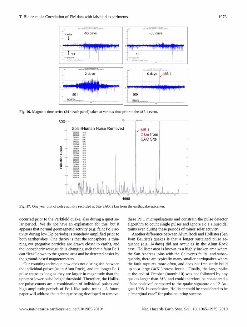
In the Hollister data, episodes where there were man-madenoise segments (e.g. the site was down for maintenance andpeople were walking around the site) were identified and ex-cluded from the pulse counting data base. Large solar storms(Kp > 7) were identified and the resulting noisy segmentswere also excluded. These segments are identified in the listshown at the left side of Fig. 17.
Similar episodes of pulse activity to the Alum Rock casecan be seen, with the largest being 2 days prior to the Hollis-ter quake.
10 August (2 days prior to the quake) showed a large pulsecount (count = 801). A more detailed examination of the timeseries showed many short pulses (<1 s) in the waveform, in-terspersed with a large, varying sine wave that appears to bea Pc 1 micropulsation train. The Kp values were<3.8 forthe 2 days prior, so we did not expect to see any Pc 1 ac-tivity during that time. However, a similar large Pc 1 train
Nat. Hazards Earth Syst. Sci., 10, 1965–1975, 2010 www.nat-hazards-earth-syst-sci.net/10/1965/2010/
T. Bleier et al.: Correlation of EM data with lab/field experiments 1973
24
1
Figure 15 Comparison of 3 independent electromagnetic indicators prior to the Alum Rock 2
earthquake 3
4
Figure 16 Magnetic time series (24 hr each panel) taken at various time prior to the M5.1 5
event 6 Fig. 16. Magnetic time series (24 h each panel) taken at various time prior to theM5.1 event.
25
1
Figure 17 One year plot of pulse activity recorded at Site SAO, 2 km from the earthquake 2
epicenter 3
4
5
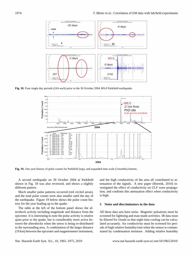
Figure 18 Four single day periods (24hrs each) prior to the Oct 30, 2004 M6.0 Parkfield 6
earthquake. 7
Fig. 17. One year plot of pulse activity recorded at Site SAO, 2 km from the earthquake epicenter.
occurred prior to the Parkfield quake, also during a quiet so-lar period. We do not have an explanation for this, but itappears that normal geomagnetic activity (e.g. faint Pc 1 ac-tivity during low Kp periods) is somehow amplified prior toboth earthquakes. One theory is that the ionosphere is thin-ning out (negative particles are drawn closer to earth), andthe ionospheric waveguide is changing such that a faint Pc 1can “leak” down to the ground area and be detected easier bythe ground-based magnetometers.
Our counting technique now does not distinguish betweenthe individual pulses (as in Alum Rock), and the longer Pc 1pulse trains as long as they are larger in magnitude than theupper or lower pulse height threshold. Therefore, the Hollis-ter pulse counts are a combination of individual pulses andhigh amplitude periods of Pc 1-like pulse trains. A futurepaper will address the technique being developed to remove
these Pc 1 micropulsations and constrain the pulse detectoralgorithm to count single pulses and ignore Pc 1 sinusoidaltrains even during these periods of minor solar activity.
Another difference between Alum Rock and Hollister (SanJuan Bautista) quakes is that a longer sustained pulse se-quence (e.g. 14 days) did not occur as in the Alum Rockcase. Hollister area is known as a highly broken area wherethe San Andreas joins with the Calaveras faults, and subse-quently, there are typically many smaller earthquakes wherethe fault ruptures more often, and does not frequently buildup to a large (M6+) stress levels. Finally, the large spikeat the end of October (month 10) was not followed by anyquakes larger thanM3, and could therefore be considered a“false positive” compared to the quake signature on 12 Au-gust 1998. In conclusion, Hollister could be considered to bea “marginal case” for pulse counting success.
www.nat-hazards-earth-syst-sci.net/10/1965/2010/ Nat. Hazards Earth Syst. Sci., 10, 1965–1975, 2010
1974 T. Bleier et al.: Correlation of EM data with lab/field experiments
25
1
Figure 17 One year plot of pulse activity recorded at Site SAO, 2 km from the earthquake 2
epicenter 3
4
5
Figure 18 Four single day periods (24hrs each) prior to the Oct 30, 2004 M6.0 Parkfield 6
earthquake. 7 Fig. 18. Four single day periods (24 h each) prior to the 30 October 2004M6.0 Parkfield earthquake.
26
1
2
Figure 19 One year history of pulse counts for Parkfield (top), and expanded time scale (3 3
mos.) bottom 4
Fig. 19. One year history of pulse counts for Parkfield (top), and expanded time scale (3 months) bottom.
A second earthquake on 30 October 2004 at Parkfieldshown in Fig. 18 was also reviewed, and shows a slightlydifferent pattern.
Much smaller pulse patterns occurred (red circled areas),and the total pulse counts were also smaller until the day ofthe earthquake. Figure 19 below shows the pulse count his-tory for the year leading up to the quake.
The table at the left of the bottom panel shows the af-tershock activity including magnitude and distance from theepicenter. It is interesting to note the pulse activity is relativequiet prior to the quake, but is considerably more activebe-tweenthe aftershocks when the stress is being re-distributedto the surrounding area. A combination of the larger distance(19 km) between the epicenter and magnetometer instrument,
and the high conductivity of the area all contributed to at-tenuation of the signals. A new paper (Bortnik, 2010) in-vestigated the effect of conductivity on ULF wave propaga-tion, and confirms this attenuation effect when conductivityis high.
5 Noise and discriminators in the data
All these data sets have noise. Magnetic pulsations must bescreened for lightning and man-made activities. IR data mustbe filtered for clouds so that night time cooling can be calcu-lated accurately. Air conductivity must be screened for peri-ods of high relative humidity/rain when the sensor is contam-inated by condensation moisture. Adding relative humidity
Nat. Hazards Earth Syst. Sci., 10, 1965–1975, 2010 www.nat-hazards-earth-syst-sci.net/10/1965/2010/

T. Bleier et al.: Correlation of EM data with lab/field experiments 1975
and geophone instruments to each site for these noise sourcesand identifying their respective signal “footprints” is impor-tant to avoid “false positives”.
Other electromagnetic “discriminators” may include spe-cific wavelengths for IR data where the spectral peaks (andtroughs) observed in the rock experiments may provide bettersignal-to-noise to detect the pre-earthquake IR signals. De-termining the specific narrow bands, and taking the ratio ofthe high-to-low bands, has yet to be done.
Total Electron Content (TEC) variations at altitude abovethe earthquake zone may be another discriminator, but pastreports have shown that the area of TEC disturbance can beas large as a continent, so spatial discrimination may be achallenge using TEC.
6 Summary and conclusions
Transient magnetic pulsations, observed in both laboratoryrock experiments and in field boulder experiments, were alsoobserved in 3 separate earthquake events (Alum Rock, Hol-lister, and Parkfield). The overall event samples are stillsmall, but the pattern of pulsations appear to have some cor-relation to the size of the earthquake (Alum RockM5.4 at14 days prior, HollisterM5.1 at 2 days prior, and ParkfieldM6 is unclear due to the larger distance between the epicen-ter and the instrument.) Another mitigating factor was thepreviously discovered high conductivity of the Parkfield areato the east of the fault (Unsworth, 1999), which possibly at-tenuated the signals.
The correlation of magnetic pulsations, air conductivity,and anomalous Infra Red, may be a more powerful indica-tor when they appear in a pre-earthquake sequence similar tothe Alum Rock earthquake, namely, pulsations and IR first,and sustained air conductivity levels seen closer to the actualevent.
It should be noted that statistically, these interesting pat-terns still represent a very small sample size, and many morequakes need to be examined. However, it does highlight theimportance of having calibrated instruments near (e.g. lessthan 30 km) from the epicenter of future medium to largeearthquake (> M5) so that the data can be obtained, com-pared, analyzed, and cross-correlated to other earthquake ex-amples. QuakeFinder is attempting to maintain the currentCalMagNet, and to develop a lower cost instrument, withinduction magnetometers and calibrated air ion detectors todetect these EM signals. The new sensors will continue toemploy relative humidity sensors and geophones to identifyvarious contaminating signal sources.
Acknowledgements.The authors wish to acknowledge funding forthis activity from C. Ford (Stellar Solutions), and J. LaBrecque(NASA Headquarters, Earth Surface and Interior Focus Area). Weare also grateful for the supporting ULF data for PKD (Parkfield)and SAO (Hollister) from the UC Berkeley Seismo-Lab, and thesolar (Kp) and humidity data from NOAA.
Edited by: M. E. ContadakisReviewed by: I.-A. Moldovan and K. Eftaxias
References
Bleier, T., Dunson, C., Maniscalco, M., Bryant, N., Bambery, R.,and Freund, F.: Investigation of ULF magnetic pulsations, airconductivity changes, and infra red signatures associated withthe 30 October Alum Rock M5.4 earthquake, Nat. Hazards EarthSyst. Sci., 9, 585–603, doi:10.5194/nhess-9-585-2009, 2009.
Bortnik, J., Bleier, T. E., Dunson, C., and Freund, F.: Esti-mating the seismotelluric current required for observable elec-tromagnetic ground signals, Ann. Geophys., 28, 1615–1624,doi:10.5194/angeo-28-1615-2010, 2010.
Freund, F.: Charge generation and propagation in rocks, J. Geody-namics, 33, 545–572, 2002.
Karakelian, D., Klemperera, S. L., Fraser-Smitha, A. C., andThompson, G. A.: Ultra-low frequency electromagnetic mea-surements associated with the 1998MW5.1 San Juan Bautista,California earthquake and implications for mechanisms of elec-tromagnetic earthquake precursors, Tectonophysics, 359, 65–79,2002.
Johnston, M. J. S., Sasai, Y., Egbert, G. D., and Mueller, R. J.:Seismomagnetic Effects from the Long-Awaited 28 September2004M6.0 Parkfield Earthquake, B. Seismol. Soc. Am., 98(4),2087–2089, 2008.
Fraser-Smith, A. C., Bernardi, A., McGill, P. R., Ladd, M. E., Hel-liwell, R. A., and Villard Jr., O. G.: Low-Frequency MagneticField Measurements near the Epicenter of the Ms 7.1 Loma Pri-eta Earthquake, Geophys. Res. Lett., 17(9), 1465–1468, 1990.
Fraser-Smith, A. C., Bernadi, A., McGill, P. R., and Villard Jr., O.G.: ULF magnetic field measurements near the epicenter of theMs 7.1 Loma Prieta Earthquake, Phys. Earth Planet. In., 68, 45–63, 1991
Hattori, K.: ULF Geomagnetic anomaly associated with 2000 IzuIslands earthquake swarm, Japan, Physics and Chemistry of theEarth, Parts A/B/C, 29(4–9), 425–435, 2004.
Liu, J. Y., Chen, Y. I., Chuo, Y. J., and Tsai, H. F.: Variations ofionospheric total electron content during the Chi-Chi earthquake,Geophys. Res. Lett., 28, 1383–1386, 2001.
Ouzounov, D., Liu, D., Kang, C., et al.: Outgoing Long Wave Ra-diationVariability from IR Satellite Data Prior to Major Earth-quakes, Tectonophysics, 431, 211–220, 2007.
Freund, F. T., Takeuchi, A., and Lau, B. W.: Electric currentsstreaming out of stressed igneous rocks – A step towards un-derstanding pre-earthquake low frequency EM emissions, Phys.Chem. Earth, 31, 389–396, 2006.
Freund, F. T.: Stimulated IR emission from rocks: Assessing astress indicator, eEarth, 2, 1–10, 2007.
Unsworth, M., Egbert, G., and Booker, J.: High-resolution electro-magnetic imaging of the San Andreas fault in Central California,J. Geophys. Res., 104(B1), 1131–1150, 1999.
www.nat-hazards-earth-syst-sci.net/10/1965/2010/ Nat. Hazards Earth Syst. Sci., 10, 1965–1975, 2010