Coriolis Flow Measurement
19
1 APPLICATION AND VERIFICATION OF CORIOLIS METERS FOR GAS MEASUREMENT KARL STAPPERT Global Business Development Manager – Natural Gas Emerson Process Management - Micro Motion, Inc. 9906A 43 rd St. Tulsa, Oklahoma 74146 Introduction Since the early 1980s, Coriolis meters have gained worldwide acceptance in gas, liquid, and slurry applications with an installed base of more than 500,000 units. Through significant design enhancements in the early 1990s Coriolis meters have rapidly gained worldwide acceptance in gas phase applications with over 35,000 meters installed world wide and most notably the 2003 publication of AGA Report Number 11, Measurement of Natural Gas by Coriolis Meter. Having the ability to bidirectionally measure almost any gas phase fluid from -400 to +400 degrees Fahrenheit without concern of error or damage due to flow profile disturbances, pulsations, regulator noise, surges, compressibility change, and density change, Coriolis meters are becoming the fiscally responsible meter of choice in many applications. Coriolis is a smaller line-size technology; the largest current offering from any vendor for gas applications is a 150mm (6”) flow diameter. The pressure drop and flow range of a Coriolis meter draws a direct relationship to the actual flow area through the meter when comparing it to other metering technologies; i.e. the flow area trough a turbine meter is area not displaced by the turbine internals and rotor, the flow area of an orifice meter is that of the orifice diameter. Because of this relationship, a Coriolis meter will typically be one pipe size smaller than a turbine meter and several sizes smaller than an orifice while having similar pressure drops at flowing pressures in the 300 ANSI class and above. 100mm (4”) Coriolis meters installed in 250mm (10”) lines Being a resonant technology with out wearing parts Coriolis meters are for the most part immune to flow factor shift and with the recent implementation of resonant modal analysis techniques, a Coriolis meter’s flow accuracy can be verified on- line without disruption in flow and without
Transcript of Coriolis Flow Measurement

1
APPLICATION AND VERIFICATION OF CORIOLIS METERS FOR GAS MEASUREMENT
KARL STAPPERT
Global Business Development Manager – Natural Gas Emerson Process Management - Micro Motion, Inc.
9906A 43rd St. Tulsa, Oklahoma 74146
Introduction Since the early 1980s, Coriolis meters have gained worldwide acceptance in gas, liquid, and slurry applications with an installed base of more than 500,000 units. Through significant design enhancements in the early 1990s Coriolis meters have rapidly gained worldwide acceptance in gas phase applications with over 35,000 meters installed world wide and most notably the 2003 publication of AGA Report Number 11, Measurement of Natural Gas by Coriolis Meter. Having the ability to bidirectionally measure almost any gas phase fluid from -400 to +400 degrees Fahrenheit without concern of error or damage due to flow profile disturbances, pulsations, regulator noise, surges, compressibility change, and density change, Coriolis meters are becoming the fiscally responsible meter of choice in many applications. Coriolis is a smaller line-size technology; the largest current offering from any vendor for gas applications is a 150mm (6”) flow diameter. The pressure drop and flow range of a Coriolis meter draws a direct relationship to the actual flow area through the meter when comparing it to other
metering technologies; i.e. the flow area trough a turbine meter is area not displaced by the turbine internals and rotor, the flow area of an orifice meter is that of the orifice diameter. Because of this relationship, a Coriolis meter will typically be one pipe size smaller than a turbine meter and several sizes smaller than an orifice while having similar pressure drops at flowing pressures in the 300 ANSI class and above.
100mm (4”) Coriolis meters installed in
250mm (10”) lines Being a resonant technology with out wearing parts Coriolis meters are for the most part immune to flow factor shift and with the recent implementation of resonant modal analysis techniques, a Coriolis meter’s flow accuracy can be verified on-line without disruption in flow and without

2
having to visually inspect the internals of the flow element. Overall, Coriolis meters offer the least amount of measurement concern and maintenance in their use compared to any other gas flow technology. This paper will discuss the theory of operation and guide the user through selection, application, maintenance process, and provide application examples of utilizing Coriolis meters for gas measurement. Theory of Operation A Coriolis meter is comprised of two main components, a sensor (primary element) and a transmitter (secondary). Coriolis meters directly infer the gas mass flow rate by sensing the Coriolis force on a vibrating tube(s). The conduit consists of one or more tubes that are vibrated at their resonant frequency by a Drive Coil. Sensing pickoff coils located on the inlet and outlet sections of the tube(s), oscillate in proportion to the sinusoidal vibration.
Coriolis Sensor Components
During flow, the vibrating tube(s) and gas mass flow couple together, due to the Coriolis force, causing twisting of the flow
tube(s) from inlet to outlet and a phase shift in the signals produced by the pickoff coils. The phase shift or difference in time, which is measured by the Coriolis meter transmitter, is directly proportional to the mass flow rate.
Coriolis Sensing/Pickoff Signals
Note that the vibration frequency of the flow tubes is proportional to the flowing density of the fluid. For gas applications, the flowing or “live” density is typically not used, as its potential error is not acceptable for gas flow measurement purposes, but can be used as an indicator of change in a Coriolis meter’s flow factor and/or clean vs. dirty. Coriolis is a direct inferential mass meter eliminating the requirement to quantify gas at flowing conditions; e.g. the need to measure flowing temperature, flowing pressure, and calculate a flowing compressibility. Equations and methods for the conversion of mass to base volume are documented in AGA Report Number 11, Measurement of Natural Gas by Coriolis Meter and AGA Report Number 8, Compressibility Factors for Natural Gas and Other Hydrocarbon Gases.

3
Meter Selection - Temperature The typical operating temperature range of Coriolis meters is -400 to +400 degrees Fahrenheit (-240 to +204 degrees Celsius). Some advanced designs have extended the high temperature operating range up to +650 degrees Fahrenheit (+343 degrees Celsius). Changes in temperature from calibration temperature can cause a bias in the Coriolis meter’s measurement relative to the elasticity change with temperature of the flow tubes. Most meter designs compensation for this effect automatically by measuring the temperature of the Coriolis meter’s flow tube(s) and applying a correction relative to the effect of Young’s modulus on the flow tube(s). Other than temperature compensation for the effect of Young’s modulus on the flow tube(s), operating/flowing temperature measurement is not required for the measurement of mass, base volume, or heating value of gas mixtures with Coriolis meters. Meter Selection - Pressure Most Coriolis meters are designed to operate at pressures up to 1480 psi (600 ANSI), with meters constructed of hastalloy tubes capable of operating at pressures up to 2220 psi (900 ANSI). Changes in operating pressure can produce a bias often referred to as the “flow pressure effect” that can be compensated for. The "flow pressure effect" of a Coriolis meter is caused by stiffening of the Coriolis
flow tube(s) as the fluid pressure in them increases. This effect is similar to a bicycle inner tube as its internal air pressure is increased; the inner tube is more flexible at a lower pressure than at a higher pressure. Pressure effect or the stiffening of the flow tubes at higher internal pressures causes the flow tube to be more resistant to the twisting force of the Coriolis Effect than they are at low pressures. As the internal flow tube(s) pressure increases, the Coriolis Effect or twisting of the flow tube(s) observed for a given mass flow rate decreases. Likewise, as the internal pressure decreases the Coriolis Effect observed for a given mass flow rate increases. The amount of over or under registration that occurs is relative to the pressure the meter was calibrated at or at which the calibration factor was determined. If Coriolis is applied at a pressure other than calibration pressure, measurement engineers should investigate pressure effect and insure appropriate compensation is implemented. Every Coriolis meter design and size has a different flow pressure effect specification. In order to correct for the flow pressure effect in a Coriolis meter’s indicated mass flow rate, the following equation should be utilized.
))(*)100/((1ReCalPStaticPEffectP
MassalMass Raw
−+=
Where:
alMassRe = Mass real or mass compensated for pressure

4
RawMass = Mass raw or mass uncompensated for pressure
EffectP = Pressure effect in percent psi
StaticP = Measurement fluid static pressure in psi
CalP = Calibration static pressure in psi Most Coriolis meter transmitters have provisions for applying an average flow pressure effect correction or for monitoring a static pressure transmitter. A Coriolis meter’s pressure effect typically ranges from a -0.001 to 0.0 percent per a psi (Worst case, a 100 psi error in pressure would equate to a 0.1% error in mass flow rate). For applications were static pressure varies significantly, typically more than 200 psi (i.e. +/- 100 psi from average), the use of a fixed/constant pressure effect correction could potentially induce unacceptable errors, live static pressure should be used for pressure effect compensation in these applications, but a high accuracy pressure transmitter is typically unwarranted. Meter Selection - Compressibility, Density, Viscosity, and Reynolds Number Although change in compressibility, density, viscosity, and Reynolds Number are a concern with almost all metering technologies, the inferred mass flow rate of a curved tube Coriolis meter is insensitive to error caused by these changes.
Meter Selection - Rate of Change High rates of change in flow are the most common cause of damage in rotating element or oscillating element flow meters, causing over speeding, and are typically found in fuel gas applications to engines, boilers, and burners. During a flow surge, the inlet flow splitter of a Coriolis meter chokes flow to the diameter of the flow tubes and the flowing densities of natural gas mixtures do not provide enough inertial force to be imparted on the flow tubes to damage them. This coupled with the ability of advanced designs to measure up to sonic velocities (choke point) removes any rate of change concern in the use of Coriolis. Meter Selection - Over Range Over ranging or over speeding often causes mechanical damage and or loss of measurement in the use of Rotary, Turbine, Orifice, and Ultrasonic meters. Advanced Coriolis meter designs can measure gas flow up to sonic velocity or choke point (approximately 1400 ft/sec with natural gas mixtures from atmospheric to 2220 psi) without loss of measurement or damage. Manufacturer’s should always be consulted on the maximum velocity limit of their particular Coriolis meter design, as not all Coriolis meter designs can measure up to choke point. From the standpoint of a high velocity gas eroding the metal of the flow tubes, high gas velocities are not an issue with Coriolis meters. The reason for this is Coriolis meters are made of nickel alloys. For gas to

5
erode a metal, the metal must oxidize from moisture in the gas and the high velocity gas then erodes the oxide layer. This is why erosion on carbon steel pipe is of concern for many piping engineers. Carbon steel is susceptible to oxidation from the moisture in the gas and therefore is susceptible to erosion from high velocity gas. A Coriolis meter’s immunity to high velocity gas erosion is similar to that of an orifice plate or sonic nozzle, in that they are made of stainless steel or other nickel alloys and are immune to high velocity erosion. If abrasive contaminants are present in the gas flow stream, erosion of the wetted meter components may be a concern when the meter is exposed to high gas velocities. This concern is application specific and when present, filtration should be used. Meter Selection - Flow Pulsation The pulsation of flow is typically of high concern in the use of every flow metering technology except Coriolis. Pulsating gas flow can cause measurement error (i.e. Fluidic Oscillation, Orifice/Differential Head, Rotary, Turbine, and Ultrasonic meters) and mechanical damage in metering technologies with load bearings and gears (i.e. Rotary, and Turbine meters). Gas flow pulsation is typically a concern on fuel gas lines to reciprocating engines, the inlet and outlet compression lines of reciprocating compressors, and the inlet and outlet lines of regulators. Advancements in Coriolis flow meter design have yielded designs that maintain accuracy over a wide range of fluid
pulsation conditions. Although Coriolis meters, for the most part, are immune to fluid pulsations, they are sensitive to pulsations at the resonant frequency of the meter’s flow tubes. In gas applications, Coriolis meters typically operate at resonant frequencies above 100 Hz or 6000 cycles per a minute, where gas pulsations are typically not found.
The resonant frequency of the flow tube(s) is meter design and flowing density dependent. Test data of a Coriolis meter subjected to fluid pulsations is shown in the following figure. Note that the area of operation sensitive to pulsation error is at the resonant frequency of the meter’s flow tubes.
Effect of Flow Pulsation on a Coriolis Meter
Although measurement error can occur when fluid pulsations are at the same frequency as the flow tube(s) frequency of resonance, convergence of flow tube(s) resonant frequency and fluid pulsation frequency is extremely rare in gas applications. High instability in the meter’s indicated flow rate coupled with fluctuating power consumption by the flow tube(s) drive coil are indicators that convergence of pulsation and resonant frequency is occurring. If this problem occurs in a
Effect of flow pulsations on a Micro Motion meterfrequency "sweep" at 2700 kg/h
-2.00
-1.50
-1.00
-0.50
0.00
0.50
1.00
1.50
2.00
0 50 100 150 200 250 300 350 400
Frequency (Hz)
Err
or (%
)

6
particular gas measurement application, flowing pressure can be reduced or increased to change the flowing density of the gas and thus the resonant frequency of the Coriolis flow tube(s). Coriolis manufacturers can also selectively pick or tune a replacement meter that operates in a higher or lower resonant frequency range to correct the problem. Meter Selection - Mechanical Vibration
Although Coriolis meters, for the most part, are immune to mechanical vibration, they are sensitive to vibrations at the resonant frequency of the flow tube(s). The resonant frequency of the flow tube(s) is meter design and fluid density dependent. Testing of a Coriolis meter subjected to mechanical vibrations is shown in the following figure. Note that the area of sensitivity is only at the resonant frequency of the meter’s flow tubes.
Vibration Effects
Although measurement error can occur when vibration disturbances are at the same frequency as the flow tube(s) frequency of resonance, convergence of flow tube(s) resonant frequency and vibration disturbances is rare and typically not a concern in most applications. Similar to pulsations, mechanical vibrations at
resonant frequency are easily diagnosed using methods called out in the “Meter Selection – Pulsations” section. If this problem occurs in a particular measurement application, Coriolis manufacturers can selectively pick or tune a replacement meter that operates in higher or lower resonant frequency range to correct the problem. Meter Selection - Gas Quality Should debris (i.e. sand, gravel, welding rods, welding slag, rodents) exist that could erode, scar, or plug the flow tubes exist, filtration should be utilized in the metering system design to protect the meter. Although fine soft particles like iron oxide, oils, and dust will not damage the flow tubes of a Coriolis meter, build-up of this debris can cause an imbalance in the flow tubes and out of specification shift in the meter’s zero. Coriolis meters have high error immunity to dirty processes because an out of specification zero caused by debris buildup will induce error on the low end of a meter’s flow range, but is typically insignificant and undetectable at flows in the high end of the flow range. In most applications, gas velocities through the flow tubes at the high end of the flow range are typically sufficient to maintain a meter’s cleanliness. The maintenance “Zero Check” will also identify if debris buildup or coating is affecting measurement accuracy. Meter Selection - Bidirectional Coriolis meters are bidirectional meters, during flow the signal from the inlet pick-off coil lags the outlet pick-off coil signal, by
-1 .5
-1
-0 .5
0
0 .5
1
1 .5
0 5 0 0 1 0 0 0 1 5 0 0 2 0 0 0 2 5 0 0
S h a k e r T a b le F r e q u e n c y , H z
Mas
s Fl
ow S
igna
l Noi
se, S
CFM

7
determining which pickoff signal is lagging flow direction is determined. Meter Selection - Measurement Accuracy The measurement accuracy of a Coriolis meter is design and fluid specific. Coriolis meters can typically measure gas mixtures at an accuracy of +/- 1% or better. Advanced designs can achieve accuracies of +/- 0.35%. Meter Selection - Range The volume flow range of a Coriolis meter is determined on the low end by minimum acceptable accuracy and worst-case drift (Zero Stability) in a meter’s zero over its specified operating range. The Zero Stability is the potential error in all indicated flow rates. Due to this fact, a Coriolis meter’s accuracy naturally improves as mass flow rate increases until a maximum accuracy, dictated by meter design and measurement fluid, is reached. The high end of a Coriolis meter’s flow range is determined by gas flow velocity. Most Coriolis meters can measure gas velocities up to 200 ft/sec and advanced designs can measure gas flow at velocities up to sonic velocity or choke point without loss of measurement or damage. Although some Coriolis meter designs can measure gas flows up to sonic velocity, a maximum allowable pressure drop dictated by the application in which they will be applied typically determines maximum flow. This is quite different from traditional flow technologies where maximum flow is where
measurement is lost and/or flow damage occurs to the flow element. Therefore, the appropriate size of Coriolis meter for an application and its flow range are determined by the following.
• Allowable Pressure Drop @ Maximum Flow
• Minimum Acceptable Accuracy @ Minimum Flow
In gas applications, if the non-linearity of gas compressibility is ignored and temperature is assumed to be constant, it can be stated that the flow through a Coriolis meter for a given pressure drop changes directly with the square root of static pressure change. With a constant pressure drop, if static pressure doubles, flow would increase by a multiplier of 1.4; i.e. 2 x (flow prior to pressure change). Likewise, if static pressure drops in half, with pressure drop constant, flow would decrease by a multiplier of 0.707; i.e. 5.0 x (flow prior to pressure change). An example of this relationship is shown in the following figure, where the turndown of multiple meters is graphed across pressure range while pressure drop across the meters is held to a constant 15 psi (the typical pressure drop of a gas turbine at maximum flow) and the minimum acceptable flow accuracy is 1%. Since flow through the meter increases with square root of static pressure change and the minimum flow through the meter is constant and relative to the minimum acceptable accuracy, applying a meter at higher pressures, in effect, increases operating range or turndown.

8
Coriolis Turndown versus Operating
Pressure In summary the available turndown or operating range for a given pressure drop can be increased by installing a Coriolis meter at high-pressure locations or upstream of regulation versus downstream. Meter Selection – Low Flow The following equation is the most utilized method for determining the minimum flow rate of a Coriolis meter.
100/%AccuracytyZeroStabilMinFlow =
Since Zero Stability can be expressed in standard volume (scf) units for a given relative density, the minimum standard volume flow rate at a user specified acceptable accuracy never changes regardless of pressure or temperature for a given meter design and size. This is different from other gas measurement technologies were the minimum flow rate varies with pressure and temperature.
Meter Selection - Maximum flow Advanced Coriolis meter designs can measure gas flows up to choke point or a flow velocity equivalent to sonic velocity (Mach 1) of the gas mixture (Approximately 1400 ft/sec on natural gas mixtures from atmospheric to 2220 psi). Although this is the case, in most applications Coriolis meters are sized to operate at ½ Mach or less due to flow noise. Although still accurate at flow velocities above ½ Mach, flow noise or the trembling of the flow tubes at velocities higher than ½ Mach will cause instability in the instantaneous flow indication. In applications were flow rates can exceed ½ Mach the flow averaging time, also referred to as flow dampening, can be extended to rectify this instability in indicated flow rate. Typically, Coriolis are sized within an acceptable pressure drop limit dictated by the application. Utilizing a set of gas reference conditions, often found in the manufacturers specifications, the following equation can be utilized for calculating the maximum flow rate relative to allowable pressure drop.
AppGas
AppGas
AppGasfGas
AppGas
fGas
vbb
fvfffGas
fAppGas
Q
QP
P
=⎥⎥⎦
⎤
⎢⎢⎣
⎡
Δ
Δ
ρ
ρρ
ρRe
Re
Re
Where:
AppGasPΔ = Maximum allowable pressure drop across the Coriolis meter with an application gas density (
AppGasfρ ) in psi
9
fGasfReρ = Density of reference gas at
flowing conditions in lb/cf fGasPReΔ = Reference differential pressure
across Coriolis meter with reference gas density (
fGasfReρ )
in psi AppGasfρ = Density of application gas at
flowing conditions in lb/cf fGasvfQ
Re = Volume flow rate of reference
gas at flowing conditions of fGasfRe
ρ and fGasPReΔ in cf/hr
AppGasbρ = Density of application gas at base conditions in lb/cf
AppGasvbQ = Volume flow rate of application gas at base conditions in cf/hr or scf/hr
Installation - Electrical Classification Most Coriolis meters are designed to meet Class 1, Division 1, and Class 1, Division 2 hazardous area classifications. Installation - Above and Below Ground Most Coriolis meters are designed for above ground installations (i.e. low flooding probability installation), but some manufacturers have hardware configurations that can be installed below ground if the electrical enclosures and conduits are properly sealed or weather proofed.
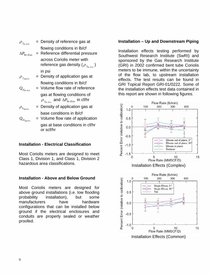
Installation – Up and Downstream Piping Installation effects testing performed by Southwest Research Institute (SwRI) and sponsored by the Gas Research Institute (GRI) in 2002 confirmed bent tube Coriolis meters to be immune, within the uncertainty of the flow lab, to upstream installation effects. The test results can be found in GRI Topical Report GRI-01/0222. Some of the installation effects test data contained in this report are shown in following figures.
Installation Effects (Complex)
Installation Effects (Common)

10
The test data shows that flow perturbations placed in close proximity upstream of a bent tube Coriolis meter is not of concern and flow condition or straight pipe up and downstream of a Coriolis meter is not required. Installation - Meter Mounting Consideration should be given to the support of the sensor and the alignment of the inlet and outlet piping flanges with the sensor. For field fabrication of piping, a spool piece should be used in place of the meter to align pipe-work prior to welding the Coriolis sensor mating flanges; i.e. slip fit is ideal. Piping should follow typical industry piping codes. Meter performance, specifically zero stability, can be affected by axial, bending, and torsion stresses. When these stresses exist, pressure, weight, and thermal expansion effects can amplify them. Although most Coriolis meters are designed to be relatively immune to these effects, utilizing properly aligned pipe-work and piping supports insures the utmost performance of any meter design and in many cases yields performance better than the manufacturer’s specifications.
Installation - Meter Orientation Coriolis meters are immune to orientation effects when measuring single-phase fluids, many fluids are rarely always in a single phase or free from sporadic contaminates in the opposite phase. As a rule in gas measurement, the Coriolis sensor should be oriented in such a way as to minimize
the possibility of heavier components, like condensate, settling in the sensor flow tube(s). Solids, sediment, plugging, coatings, or trapped liquids can affect the meter performance, especially when present during zeroing of the meter. Allowable sensor orientations will depend on the application and the geometry of the vibrating flow tube(s). In gas service, the ideal orientation of the sensor is with the flow tubes in the upright position. Installation – Piping Configuration Curved or Bent Tube Coriolis flow sensors are immune to velocity profile distortion and swirl effects, thus allowing the designer flexibility restricted only by good piping support practices to minimize structural stresses on the sensor body. The piping configuration of a Coriolis installation should consist of block valves up and downstream of the Coriolis meter with bleed valves to facilitate purging of the piping, zeroing of the meter, and maintenance procedures. A bypass should be installed around the meter if interruption of service to the customer is an issue.
Typical Coriolis Meter Installation

11
Metrology - Calibration Due to the variability of manufacturing processes, all Coriolis meters require a flow calibration to adjust their performance to the accuracy limits inherent to their particular design. As a common practice, most Coriolis manufacturers capitalize on the economics and high stability of a water calibration to perform these calibrations. Some advanced Coriolis meter designs are immune to fluid phase, density, and viscosity; enabling water calibrations to transfer to all other fluids; i.e. gas, liquid, and slurries. Testing by numerous European and North American flow labs has confirmed the transferability of water calibration data on a Coriolis meter to gas applications. Most notably testing sponsored by the Gas Research Institute in 2004 and documented in report GRI-04/172, which covers water to gas transferability and wet gas performance of Coriolis meters. Conclusions in the report state, “The single fluid calibration tests show that a water calibration of a Coriolis mass flow meter can be used for natural gas applications without loss of accuracy”.
GRI 04/0172 Water, Air, and Gas
Transferability Data
Industry testing has shown there is minimal benefit, from a calibration uncertainty perspective, in performing a gas calibration over a water calibration on Coriolis meters intended for gas measurement. Although this is the case the user should review industry recommended practices, standards, and regulatory requirements when establishing calibration policy for Coriolis. Coriolis meters are an attractive technology when the availability, capability, or economic viability of gas calibrations is limited. Highly accurate water calibrations and construction of water calibration facilities are achieved at a fraction the cost of their gas counterparts. Metrology – Volume Measurement To accurately quantify the mass output of a Coriolis meter applied at pressures other than calibration pressure, a flow pressure effect correction must be applied. Every Coriolis meter design and size has a different flow pressure effect specification. In order to correct for the flow pressure effect in a Coriolis meter’s indicated mass flow rate, the following equation should be utilized.
))(*)100/((1ReCalPStaticPEffectP
MassalMass Raw
−+=
Where:
alMassRe = Mass real or mass compensated for pressure
RawMass = Mass raw or mass uncompensated for pressure
EffectP = Pressure effect in percent psi

12
StaticP = Measurement fluid static pressure in psi
CalP = Calibration static pressure in psi For gas applications, the measurement accuracy of density by a Coriolis meter is relative to a liquid densitometer’s accuracy, this does not meet the accuracies required for gas measurement. Therefore the on-line density from the meter is not used for flow measurement with gas; rather the relative density or base density of the gas is entered into a flow computer as determined from either sampling methods or on-line gas analysis. It should be noted that the gas physical property information required by AGA8 Gross Method 1, Gross Method 2, or Detail Method and procedural methods for applying this information in the use of a Coriolis meter are identical to those required by volumetric meters; i.e. Turbine, Orifice, Rotary, and Ultrasonic. Coriolis technology uses the following calculations to output a highly accurate standard or normal volumetric output.
)(
)(
(gas))(
)(
(gas))(
x
Mass
Mass
AirbGas
gas
Gasb
gas
GrSCF
SCF
ρ
ρ
=
=
bb
rbb
TRZMP
x x x
(Gas) =ρ
Where: SCF = Volume at bT and bP Mass = Weight of gas (Coriolis output)
bρ = Density at bT and bP
bT = Temperature at base conditions
bP = Pressure at base conditions
bZ = Compressibility at base
conditions ( bT and bP )
)(GasrG = Real Gravity at bT and bP R = Universal gas constant
rM = Gas Molar Weight Field Maintenance and Meter Verification The field maintenance of a Coriolis meter is an inspection process consisting of the following
1) Zero Check 2) Transmitter Diagnostics Check 3) Sensor Diagnostics Check
Field Maintenance – Zero Check The meter zero should be checked periodically and reset if it does not meet the manufacturer’s specifications. At a minimum, inspection of the meters zero should be performed seasonally in the first year of operation, to identify any installation or process issues. Drift in Zero Reading Product buildup, erosion, or corrosion will affect the meter performance. Product buildup (coating) may bias the meter zero. It should be noted that a zero shift will affect a Coriolis meter’s accuracy more at low flows than at high flows. This is dictated by the “MinFlow” equation called out in the previous “Meter Selection – Low Flow”

13
section of this document. If the buildup is causing a shift in the meter zero, cleaning and re-zeroing the meter should bring performance back to its original performance specification. If coating of the sensor continues, the zero may continue to drift. Although rare, erosion or corrosion will permanently affect meter calibration and will compromise sensor integrity. When used within the specified fluid and ambient condition limits, fatigue of the sensing tubes of a Coriolis meter due to vibration during a meter’s life is not of concern, and does not need to be considered when inspecting a meter. However, operating the meter in more extreme corrosive or erosive applications will shorten the meter’s expected lifetime. Checking and Adjusting Zero Improper zeroing will result in measurement error. In order to adjust the zero of the meter there must be no flow through the flow sensor and the sensor should be filled with gas at process conditions. Even though the stream is not flowing, the flow meter may indicate a small amount of flow, either positive or negative. Causes for the zero error are usually related to the differences between the calibration conditions and the actual installation, which include the following:
• Differences between the calibration media density and the application gas density
• Differences in temperature • Differing mounting conditions
The meter should read a mass flow rate that is less than the manufacturer’s zero
stability specification under the no-flow condition. The zeroing of the meter should be performed at nominal operating condition with no flow through the meter. Once it has been confirmed that there is no flow through the meter, the zeroing procedure specified by the meter manufacturer should be followed. Field Maintenance – Diagnostics A diagnostic LED(s) and display may be provided to indicate operating status of the sensor and secondary (transmitter) elements. The diagnostics of the Coriolis transmitter verify the integrity of the CPU and insure operational parameters are not outside their limits. Coriolis sensor diagnostics verify the sensing components of the sensor are not damaged and operating within normal limits. Sensor diagnostics also provide insight into the process flow conditions and potential measurement problems with them. Advanced Coriolis sensor designs also provide an on-line “Structural Integrity Verification” of the flow tubes. The flow tube structure of a Coriolis sensor dictates its flow calibration factor. The structural integrity method utilizes flow tube(s) stiffness to infer density and mass calibration factor change capitalizing on resonant modal analysis techniques to actively test flow tube(s) stiffness characteristics (vertical, horizontal, and rotational) inferring the stability of mass and density calibration factors. Structural Integrity Verification is a significant advancement in Coriolis technology and

14
flow metering technologies in general. This capability makes Coriolis the only flow measurement technology available today that can verify its accuracy without interruption in flow, the use of a flow reference, inspection of primary element, and calibration verification of secondary elements. CAPEX Capital Expenditures (“CAPEX”) to implement Coriolis measurement will vary dependent upon meter design, size, pressure ratings, materials of construction, and accuracy. Typical capital expenditures required in the implementation of a Coriolis metering system include the following.
• Coriolis Sensor • Flow Computer or Transmitter • Power System • Installation and Startup
Coriolis technology reduces or eliminates several of the capital expenditures required in the application of other gas flow technologies and typically associated with natural gas metering. Typical capital expenditures that are reduced or eliminated are as follows. • Pressure measurement - Typically
not required for flow measurement and if required, high accuracy is unwarranted
• Temperature measurement - Integral to Coriolis sensor design
• Specialty upstream and downstream piping and/or flow conditioning
• Gas flow calibration of sensor - Factory water flow calibration transfers to natural gas measurement
• Installation and startup OPEX Operating Expenditures (“OPEX”) to maintain Coriolis measurement will vary dependent upon meter design, power system, cleanliness of process, and accuracy verification procedures required by meter design, adopted by the user’s organization, or dictated by regulatory requirements. Typical operating expenditures required in the use a Coriolis metering system include the following.
• Routine inspection of sensor zero and diagnostics
• The replacement of battery backup power cells, if used, when their efficiency has declined.
Coriolis technology reduces or eliminates several of the operating expenditures associated with gas flow technologies. Typical operating expenditures that are reduced or eliminated are as follows.
• Pressure calibration – Although pressure measurement, if used, will require periodic verification its recalibration with a precision reference is typically not required.
• Temperature measurement - Although temperature measurement will require periodic verification its recalibration with a precision reference is typically not required

15
• Inspection and cleaning of specialty upstream and downstream piping and/or flow conditioning
• Validation of flow factor - Coriolis meters can be validated with water flow references, which are typically more economical than that of their natural gas counterparts. Some Coriolis designs incorporate advanced structural diagnostics that verify the sensor’s flow factor or identify the requirement of recalibration. Structural diagnostics eliminate unnecessary flow validations or recalibrations.
Application Examples Coriolis meters are applied in a wide variety of applications, from the “wellhead to the burner tip”. Coriolis meters are primarily a smaller line size meter, ideally suited to the following gas metering “sweet spots”:
• Line sizes 250mm (10”) and smaller • 300 ANSI through 900 ANSI • High turndown requirements • Dirty, wet, or sour gas where
maintenance can be an issue with other technologies
• There is no room for long straight-runs
• Changing gas composition and density
• Sudden changes in gas flow velocity (fuel gas applications)
• Pulsating gas flows (fuel gas and compression gas in the use of reciprocating compressors)
• Applications were abnormally high flow rates can occur.
Coriolis meters can be sized for very low-pressure drop (100” H2O), but can also be installed upstream of the pressure regulator with high pressure drops of up to 40% of available pressure for increased turndown without concern of damage or malfunction due to flow noise. For instance, in one application for custody transfer of nitrogen, a 50-psid drop (1390” H2O) was allowed across the Coriolis meter and the pressure regulator adjusted accordingly. This allowed the use of a 1” Coriolis meter instead of a 3” meter downstream of the regulator and a 40:1 useable turndown (Better than 1% accuracy at minimum flow and an average 0.35% base volume accuracy over 95% of the upper flow range). Separator gas: Saudi Aramco uses a number of Coriolis meters on both the liquid and gas side of separators. This application is of particular note because the gas stream is wet, with entrained hydrocarbon condensates. Measurement of this stream is within a few percent over a wide range of conditions, greatly enhancing separator operation and accurately quantifying the value of the gas/entrained liquid hydrocarbon stream.
Coriolis Liquid and Gas Separator
Measurement

16
Fuel Control: A major US vendor of gas turbines designs a high-efficiency, low emissions offering. This design utilizes a trio of Coriolis meters to measure the natural gas burned in each of three combustion zones. The combination of no damage due to flow rate of change at start-up, high turndown, high accuracy, immunity to vibration in a very high vibration environment, along with ease of installation due to no straight pipe run requirement, makes Coriolis the technology of choice. Coriolis Fuel Gas Measurement on a Gas
Turbine Natural Gas Fiscal Transfer: One specific example of gas measurement capability is at a natural gas utility in Western Australia. Two 3” meters are used in parallel with a third used as a “hot spare” for monthly verifications of the transfer meters. The justification for using the Coriolis meters was based on installation and calibration/maintenance cost improvements over the more traditional gas metering systems. Since Coriolis meters require no straight runs or flow conditioning the installed costs were reduced by five times, even with the parallel meters required to handle the highest flows.
Additionally, periodic maintenance costs were reduced due to the intrinsic reliability of Coriolis meters (i.e. no moving parts). Similarly, reliability improvements reduced calibration and proving costs. Internal checks by the customer have shown agreement to better than 0.1% on all gas transfers over a 6-year period.
Western Australia: Previous installation using turbine meters for 50:1 turndown
“After” installation since 1996, with two operating and one “hot spare” meter
for 80:1 turndown.

17
Natural Gas Storage: A storage field in Hungary utilizes 27 two-inch Coriolis meters for the injection and withdrawal measurement of natural gas. The storage reservoir consists of a multilayer sandstone formation with an aquifer flowing through it. Due to the complexity of managing the water level in a sandstone formation on the injection and withdrawal of natural gas, multiple small wells are required. The withdrawal gas is also fully saturated, contains H2S, and during high flows the wells produce sand. In this difficult application, only Coriolis meters can provide bidirectional measurement, long-term accuracy, and achieve the wide turndowns required for reservoir management.
Coriolis Natural Gas Storage Measurement
in Hungary The following graph shows performance testing on a Coriolis meter from an identical metering application in Redfield, Iowa where the meter tested was subjected to saturated gas laden with H2S, sand, and iron sulfide over a 9-year period. The post 9 year data shows the meter is maintaining an accuracy of 0.5% or better and still performing within the manufacturers specifications.
Energy Metering: Energy per SCF can vary as much as 10 times that of energy per a unit weight for Hydrocarbons. If the total concentration of CO2 and N2 in the natural gas mixture remains fairly constant and most of the variation in composition is related to hydrocarbon concentrations, an average heating value can be utilized for energy measurement allowing Coriolis to achieve total energy accuracies unparalleled by volumetric meters utilizing the same average value. A Coriolis meter by itself offers a very affordable method of inferring energy flow rates on some natural gas streams.
DS150S Compressed Air Test, 250 psia, 70°FS/N 138085, Installed 1991
Natural Gas Cavern Storage (bi-directional use)
-3
-2
-1
0
1
2
3
0 50 100 150 200 250lbs/min
erro
r, %
spec spec Air cal (May 2000) Water cal (May 2000) Water cal (Sept 1991)

18
Combustion control to boilers: In this application, a Pulp mill in Quebec sought a more reliable way to meet EPA emissions requirements. Combustion control was easier, based on the mass ratio between the natural gas and combustion air. High turndown and concern over damage to the measurement element due to flow surge when the boilers fired drove the selection of Coriolis for this application.
Combustion control application to boilers Ethylene gas transfer: Ethylene is commonly viewed as a difficult to measure gas, due to its highly non-ideal nature. In this application, Coriolis meters are used for intra-plant transfers attaining accuracies unattainable by volumetric meters, helping to meet both unit mass-balance goals, as well as reactor feed rate requirements.
Ethylene application, where ethylene is fed continuously to a polymerization reactor
Summary Although a relatively new technology for the natural gas industry, Coriolis meters have gained worldwide acceptance for many fluids and in other industries. With a worldwide installed base of over 500,000 units, Coriolis technology is seeing expanded use for both liquid petroleum and natural gas. A number of countries and organizations have published standards or are in the process of studying the technology. Most notably is AGA and API who have jointly published AGA Report No. 11 / API MPMS Chapter 14.9, Measurement of Natural Gas by Coriolis Meter. Technology limitations of earlier designs have largely been overcome, with high accuracy measurement now possible at low-pressure drop. Coriolis “sweet spots” are mainly in lines of 250mm (10”) and smaller, 300 to 900 ANSI, where high turndown is needed, flow conditioning with other technologies to meet new AGA requirements is costly, flow surges occur, pulsations are present, energy metering is required, and/or the gas is of dirty, sour, or of changing composition. Coriolis technology merits serious consideration as a bona fide contender to complement Ultrasonic in low cost of ownership metering for natural gas applications. These two technologies overlap in the 100mm (4”) to 200mm (8”) line size range.

19
A ½” Coriolis and 12” ultrasonic in a fuel gas metering installation.
Third-party data from CEESI, Pigsar, SwRI, and others show little if any effect of flow profile and the transferability of a factory water calibration to natural gas measurement applications. Common Coriolis gas applications range from wellhead separator, medium to high-pressure fiscal metering, and fuel gas to power turbines, reciprocating engines, and boilers. As users of gas meters investigate Coriolis they are finding it to be the fiscally responsible choice for gas measurement in today’s competitive business environment.