CoreLink DMA-330 DMA Controller - ARM Information...
147
Copyright © 2007, 2009-2010, 2012 ARM. All rights reserved. ARM DDI 0424D (ID072812) CoreLink ™ DMA-330 DMA Controller Revision: r1p2 Technical Reference Manual
Transcript of CoreLink DMA-330 DMA Controller - ARM Information...
CoreLink™ DMA-330 DMA ControllerRevision: r1p2
Technical Reference Manual
Copyright © 2007, 2009-2010, 2012 ARM. All rights reserved.ARM DDI 0424D (ID072812)

CoreLink DMA-330 DMA Controller Technical Reference Manual
Copyright © 2007, 2009-2010, 2012 ARM. All rights reserved.
Release Information
The following changes have been made to this book.
Proprietary Notice
Words and logos marked with ™ or ® are registered trademarks or trademarks of ARM® in the EU and other countries, except as otherwise stated below in this proprietary notice. Other brands and names mentioned herein may be the trademarks of their respective owners.
Neither the whole nor any part of the information contained in, or the product described in, this document may be adapted or reproduced in any material form except with the prior written permission of the copyright holder.
The product described in this document is subject to continuous developments and improvements. All particulars of the product and its use contained in this document are given by ARM in good faith. However, all warranties implied or expressed, including but not limited to implied warranties of merchantability, or fitness for purpose, are excluded.
This document is intended only to assist the reader in the use of the product. ARM shall not be liable for any loss or damage arising from the use of any information in this document, or any error or omission in such information, or any incorrect use of the product.
Where the term ARM is used it means “ARM or any of its subsidiaries as appropriate”.
Confidentiality Status
This document is Non-Confidential. The right to use, copy and disclose this document may be subject to license restrictions in accordance with the terms of the agreement entered into by ARM and the party that ARM delivered this document to.
Product Status
The information in this document is final, that is for a developed product.
Web Address
http://www.arm.com
Change history
Date Issue Confidentiality Change
19 December 2007 A Non-Confidential First issue for r0p0
19 November 2009 B Non-Confidential First issue for r1p0
22 July 2010 C Non-Confidential First issue for r1p1
29 June 2012 D Non-Confidential First issue for r1p2.
ARM DDI 0424D Copyright © 2007, 2009-2010, 2012 ARM. All rights reserved. iiID072812 Non-Confidential

ContentsCoreLink DMA-330 DMA Controller Technical Reference Manual
PrefaceAbout this book ........................................................................................................... viFeedback ..................................................................................................................... x
Chapter 1 Introduction1.1 About the DMAC ...................................................................................................... 1-21.2 Compliance .............................................................................................................. 1-41.3 Features ................................................................................................................... 1-51.4 Interfaces ................................................................................................................. 1-61.5 Configurable options ................................................................................................ 1-71.6 Test features ............................................................................................................ 1-81.7 Product documentation, design flow, and architecture ............................................ 1-91.8 Product revisions ................................................................................................... 1-111.9 Terminology ........................................................................................................... 1-12
Chapter 2 Functional Overview2.1 Overview .................................................................................................................. 2-22.2 DMAC interfaces ...................................................................................................... 2-42.3 Operating states ...................................................................................................... 2-82.4 Initializing the DMAC ............................................................................................. 2-112.5 Using the APB slave interfaces ............................................................................. 2-132.6 Peripheral request interface ................................................................................... 2-152.7 Using events and interrupts ................................................................................... 2-232.8 Aborts .................................................................................................................... 2-252.9 Security usage ....................................................................................................... 2-292.10 Constraints and limitations of use .......................................................................... 2-332.11 Programming restrictions ....................................................................................... 2-35
ARM DDI 0424D Copyright © 2007, 2009-2010, 2012 ARM. All rights reserved. iiiID072812 Non-Confidential

Contents
Chapter 3 Programmers Model3.1 About this programmers model ................................................................................ 3-23.2 Register summary .................................................................................................... 3-53.3 Register descriptions ............................................................................................. 3-11
Chapter 4 Instruction Set4.1 Instruction syntax conventions ................................................................................. 4-24.2 Instruction set summary ........................................................................................... 4-34.3 Instructions .............................................................................................................. 4-44.4 Assembler directives .............................................................................................. 4-21
Appendix A Signal DescriptionsA.1 Clocks and resets .................................................................................................... A-2A.2 AXI signals ............................................................................................................... A-3A.3 APB signals ............................................................................................................. A-6A.4 Peripheral request interface ..................................................................................... A-7A.5 Interrupt signals ....................................................................................................... A-8A.6 Tie-off signals .......................................................................................................... A-9
Appendix B MFIFO Usage OverviewB.1 About MFIFO usage overview ................................................................................. B-2B.2 Aligned transfers ...................................................................................................... B-3B.3 Unaligned transfers .................................................................................................. B-5B.4 Fixed transfers ......................................................................................................... B-9
Appendix C Revisions
ARM DDI 0424D Copyright © 2007, 2009-2010, 2012 ARM. All rights reserved. ivID072812 Non-Confidential
Preface
This preface introduces the CoreLink™ DMA-330 DMA Controller Technical Reference Manual. It contains the following sections:• About this book on page vi.• Feedback on page x.
ARM DDI 0424D Copyright © 2007, 2009-2010, 2012 ARM. All rights reserved. vID072812 Non-Confidential

Preface
About this bookThis book is for the CoreLink DMA Controller (DMA-330).
Product revision status
The rnpn identifier indicates the revision status of the product described in this book, where:rn Identifies the major revision of the product.pn Identifies the minor revision or modification status of the product.
Intended audience
This book is written for system designers, system integrators, and programmers who are designing or programming a System-on-Chip (SoC) device that uses the DMC-330.
Using this book
This book is organized into the following chapters:
Chapter 1 Introduction Read this for a high-level view of the DMAC.
Chapter 2 Functional Overview Read this for a description of the major interfaces and components of the DMAC. The chapter also describes how they operate.
Chapter 3 Programmers Model Read this for a description of the DMAC memory map and registers.
Chapter 4 Instruction Set Read this for a description of the instruction set.
Appendix A Signal Descriptions Read this for a description of the DMAC input and output signals.
Appendix B MFIFO Usage Overview Read this for a description of how the DMAC uses the MFIFO.
Appendix C Revisions Read this for a description of the technical changes between released issues of this book.
Glossary
The ARM Glossary is a list of terms used in ARM documentation, together with definitions for those terms. The ARM Glossary does not contain terms that are industry standard unless the ARM meaning differs from the generally accepted meaning.
See ARM Glossary, http://infocenter.arm.com/help/topic/com.arm.doc.aeg0014-/index.html.
Conventions
This book uses the conventions that are described in:• Typographical conventions on page vii.• Timing diagrams on page vii.
ARM DDI 0424D Copyright © 2007, 2009-2010, 2012 ARM. All rights reserved. viID072812 Non-Confidential

Preface
• Signals on page viii.
Typographical conventions
The following table describes the typographical conventions:
Timing diagrams
The figure named Key to timing diagram conventions explains the components used in timing diagrams. Variations, when they occur, have clear labels. You must not assume any timing information that is not explicit in the diagrams.
Shaded bus and signal areas are undefined, so the bus or signal can assume any value within the shaded area at that time. The actual level is unimportant and does not affect normal operation.
Key to timing diagram conventions
Style Purpose
italic Introduces special terminology, denotes cross-references, and citations.
bold Highlights interface elements, such as menu names. Denotes signal names. Also used for terms in descriptive lists, where appropriate.
monospace Denotes text that you can enter at the keyboard, such as commands, file and program names, and source code.
monospace Denotes a permitted abbreviation for a command or option. You can enter the underlined text instead of the full command or option name.
monospace italic Denotes arguments to monospace text where the argument is to be replaced by a specific value.
monospace bold Denotes language keywords when used outside example code.
<and> Encloses replaceable terms for assembler syntax where they appear in code or code fragments. For example:MRC p15, 0 <Rd>, <CRn>, <CRm>, <Opcode_2>
SMALL CAPITALS Used in body text for a few terms that have specific technical meanings, that are defined in the ARM glossary. For example, IMPLEMENTATION DEFINED, IMPLEMENTATION SPECIFIC, UNKNOWN, and UNPREDICTABLE.
Clock
HIGH to LOW
Transient
HIGH/LOW to HIGH
Bus stable
Bus to high impedance
Bus change
High impedance to stable bus
ARM DDI 0424D Copyright © 2007, 2009-2010, 2012 ARM. All rights reserved. viiID072812 Non-Confidential

Preface
Timing diagrams sometimes show single-bit signals as HIGH and LOW at the same time and they look similar to the bus change shown in Key to timing diagram conventions on page vii. If a timing diagram shows a single-bit signal in this way then its value does not affect the accompanying description.
Signals
The signal conventions are:
Signal level The level of an asserted signal depends on whether the signal is active-HIGH or active-LOW. Asserted means:• HIGH for active-HIGH signals.• LOW for active-LOW signals.
Lower-case n At the start or end of a signal name denotes an active-LOW signal.
ARM DDI 0424D Copyright © 2007, 2009-2010, 2012 ARM. All rights reserved. viiiID072812 Non-Confidential

Preface
Additional reading
This section lists publications by ARM and by third parties.
See Infocenter, http://infocenter.arm.com, for access to ARM documentation.
ARM publications
This book contains information that is specific to this product. See the following documents for other relevant information:
• CoreLink DMA-330 DMA Controller Implementation Guide (ARM DII 0192).
• CoreLink DMA-330 DMA Controller Integration Manual (ARM DII 0193).
• AMBA Designer ADR-400 User Guide (ARM DUI 0333).
• AMBA Designer ADR-400 Installation Guide (ARM DUI 0456).
• CoreLink DMA-330 DMA Controller Supplement to AMBA Designer ADR-400 User Guide (ARM DSU 0009).
• ARM Architecture Reference Manual, ARMv7-A and ARMv7-R edition (ARM DDI 0406).
• AMBA AXI™ and ACE™ Protocol Specification, AXI3™, AXI4™, and AXI4-Lite™, ACE™ and ACE-Lite™ (ARM IHI 0022).
• AMBA APB Protocol Specification (ARM IHI 0024).
Other publications
This section lists relevant documents published by third parties:
• JEDEC Standard Manufacturer’s Identification Code, JEP106, http://www.jedec.org.
ARM DDI 0424D Copyright © 2007, 2009-2010, 2012 ARM. All rights reserved. ixID072812 Non-Confidential

Preface
FeedbackARM welcomes feedback on this product and its documentation.
Feedback on this product
If you have any comments or suggestions about this product, contact your supplier and give:
• The product name.
• The product revision or version.
• An explanation with as much information as you can provide. Include symptoms and diagnostic procedures if appropriate.
Feedback on content
If you have comments on content then send an e-mail to [email protected]. Give:• The title.• The number, ARM DDI 0424D.• The page numbers to which your comments apply.• A concise explanation of your comments.
ARM also welcomes general suggestions for additions and improvements.
ARM DDI 0424D Copyright © 2007, 2009-2010, 2012 ARM. All rights reserved. xID072812 Non-Confidential

Chapter 1 Introduction
This chapter introduces the DMA Controller (DMAC). It contains the following sections:• About the DMAC on page 1-2.• Compliance on page 1-4.• Features on page 1-5.• Interfaces on page 1-6.• Configurable options on page 1-7.• Test features on page 1-8.• Product documentation, design flow, and architecture on page 1-9.• Product revisions on page 1-11.• Terminology on page 1-12.
Note The DMAC product designator is either PL330 or DMA-330 and depends on the product revision as follows:
r0p0 PL330.
r1p0 or later DMA-330.
ARM DDI 0424D Copyright © 2007, 2009-2010, 2012 ARM. All rights reserved. 1-1ID072812 Non-Confidential

Introduction
1.1 About the DMACThe DMAC is an Advanced Microcontroller Bus Architecture (AMBA) compliant peripheral that is developed, tested, and licensed by ARM.
The DMAC provides an AXI master interface to perform the DMA transfers and two APB slave interfaces that control its operation. The DMAC implements TrustZone® secure technology with one APB interface operating in the Secure state and the other operating in the Non-secure state. See the ARM Architecture Reference Manual for more information about TrustZone technology.
The DMAC includes a small instruction set that provides a flexible method of specifying the DMA operations. This enables it to provide greater flexibility than the fixed capabilities of a Linked-List Item (LLI) based DMA controller. To minimize the program memory requirements, the DMAC uses variable-length instructions.
Figure 1-1 shows the interfaces that are available on the DMAC.
Figure 1-1 Interfaces on the DMAC
Figure 1-2 shows an example system that contains a DMAC.
Figure 1-2 Example system
DMAC
Non-secure APB slave interface
Secure APB slave interface
Interrupts [x:0]Peripheral request interface [x:0]
AXI master interface
SMC
DMC DRAM
Flash memory
Secure APB slave interface
AXI master
interface
DMAC
AXI Interconnect
AXI-APB bridge
GPIO
Non-secure
APB slave interface
Peripheral request interface
Interrupt outputs
AXI-APB bridge
UART
Timer
ARM processor
ARM processor
ARM DDI 0424D Copyright © 2007, 2009-2010, 2012 ARM. All rights reserved. 1-2ID072812 Non-Confidential

Introduction
The example system contains:• AXI bus masters:
— A DMAC.— Two ARM processors.
• An AXI interconnect and two AMBA protocol bridge components.• AMBA slaves:
— A Dynamic Memory Controller (DMC).— A Static Memory Controller (SMC).— A Timer.— A General Purpose Input-Output (GPIO).— A Universal Asynchronous Receiver-Transmitter (UART).
The AXI interconnect enables each bus master to access the slaves. The ARM processors can access the APB interfaces of the DMAC by using the appropriate AXI to APB bridge component.
ARM DDI 0424D Copyright © 2007, 2009-2010, 2012 ARM. All rights reserved. 1-3ID072812 Non-Confidential

Introduction
1.2 ComplianceThe DMAC is compliant with the following standards and protocols:• AMBA AXI3 protocol.• AMBA APB3 protocol.
ARM DDI 0424D Copyright © 2007, 2009-2010, 2012 ARM. All rights reserved. 1-4ID072812 Non-Confidential

Introduction
1.3 FeaturesThe DMAC provides the following features:
• An instruction set that provides flexibility for programming DMA transfers.
• A single AXI master interface that performs the DMA transfers.
• Dual APB slave interfaces, designated as secure and non-secure, for accessing registers in the DMAC.
• Supports TrustZone technology.
• Supports multiple transfer types:— Memory-to-memory.— Memory-to-peripheral.— Peripheral-to-memory.— Scatter-gather.
• Configurable RTL that enables you to optimize the DMAC for the application.
• Programmable security state for each DMA channel.
• Signals the occurrence of various DMA events using the interrupt output signals.
ARM DDI 0424D Copyright © 2007, 2009-2010, 2012 ARM. All rights reserved. 1-5ID072812 Non-Confidential

Introduction
1.4 InterfacesThe DMAC has the following external interfaces:• AMBA AXI3 master interface, for transfer of memory data to or from an AMBA slave.• AMBA APB3 slave interface, for programming the DMAC.
ARM DDI 0424D Copyright © 2007, 2009-2010, 2012 ARM. All rights reserved. 1-6ID072812 Non-Confidential

Introduction
1.5 Configurable optionsThe DMAC has the following configurable options:• AXI data bus width.• Number of active AXI read transactions.• Number of active AXI write transactions.• Number of DMA channels.• Depth of the internal data buffer.• Number of lines in the instruction cache and how many words a line contains.• Depth of the read instruction queue.• Depth of the write instruction queue.• Number of peripheral request interfaces.• Request acceptance capability of a peripheral request interface.• Number of interrupt output signals.
Note See the CoreLink DMA-330 DMA Controller Supplement to AMBA Designer ADR-400 User Guide for information about how to configure these features and the values that you can assign.
ARM DDI 0424D Copyright © 2007, 2009-2010, 2012 ARM. All rights reserved. 1-7ID072812 Non-Confidential

Introduction
1.6 Test featuresThe DMAC does not provide test features.
ARM DDI 0424D Copyright © 2007, 2009-2010, 2012 ARM. All rights reserved. 1-8ID072812 Non-Confidential

Introduction
1.7 Product documentation, design flow, and architectureThis section describes the DMAC books, how they relate to the design flow, and the relevant architectural standards and protocols.
See Additional reading on page ix for more information about the books described in this section.
1.7.1 Documentation
The DMAC documentation is as follows:
Technical Reference Manual The Technical Reference Manual (TRM) describes the functionality and the effects of functional options on the behavior of the DMAC. It is required at all stages of the design flow. Some behavior described in the TRM might not be relevant because of the way that the DMAC is implemented and integrated. If you are programming the DMAC then contact:• The implementer to determine the build configuration of the
implementation.• The integrator to determine the signal configuration of the SoC that you are
using.The TRM complements protocol specifications and relevant external standards. It does not duplicate information from these sources.
User Guide The User Guide (UG) describes:• The available build configuration options and related issues in selecting
them.• How to use AMBA Designer to:
— Configure the DMAC.— Generate the Register Transfer Level (RTL).
The UG is a confidential book that is only available to licensees.
Implementation Guide The Implementation Guide (IG) describes:• The Out-Of-Box instructions.• The synthesis constraints.The ARM product deliverables include reference scripts and information about using them to implement your design.The IG is a confidential book that is only available to licensees.
Integration Manual The Integration Manual (IM) describes how to integrate the DMAC into a SoC. It includes describing the signals that the integrator must tie off to configure the macrocell for the required integration. Some of the integration is affected by the configuration options used when implementing the DMAC.The IM is a confidential book that is only available to licensees.
ARM DDI 0424D Copyright © 2007, 2009-2010, 2012 ARM. All rights reserved. 1-9ID072812 Non-Confidential

Introduction
1.7.2 Design flow
The DMAC is delivered as synthesizable RTL. Before it can be used in a product, it must go through the following process:
1. Implementation. The implementer configures and synthesizes the RTL to produce a hard macrocell.
2. Integration. The integrator connects the implemented design into an SoC. This includes connecting it to a memory system and peripherals.
3. Programming. The system programmer develops the software required to control the DMAC and tests the required application software.
Each stage of the process:• Can be performed by a different party.• Can include options that affect the behavior and features at the next stage:
Build configuration The implementer chooses the options that affect how the RTL source files are pre-processed. They usually include or exclude logic that can affect the area or maximum frequency of the resulting macrocell.
Configuration inputs The integrator configures some features of the DMAC by tying inputs to specific values. These configurations affect the start-up behavior prior to the software taking control. They can also limit the options available to the software. See Tie-off signals on page A-9.
Software control The programmer updates the DMAC by programming particular values into software-visible registers. This affects the behavior of the DMAC.
1.7.3 ARM architecture and protocol information
The DMAC complies with, or implements, the ARM specifications described in:• AMBA AXI3 protocol. See the AMBA AXI and ACE Protocol Specification.• AMBA APB3 protocol. See the AMBA APB Protocol Specification.
ARM DDI 0424D Copyright © 2007, 2009-2010, 2012 ARM. All rights reserved. 1-10ID072812 Non-Confidential

Introduction
1.8 Product revisionsThis section describes the differences in functionality between the product revisions:
r0p0 First release.
r0p0 - r1p0 This release includes:• Precise lockup detection, see Watchdog abort on page 2-26.• No store before load, see Abort sources on page 2-25.• Addition of the WD Register, see Watchdog Register on page 3-40.• Addition of the Add Negative Halfword instruction, DMAADNH, see
DMAADNH on page 4-4.
r1p0 - r1p1 No differences in functionality.
r1p1 - r1p2 No differences in functionality.
ARM DDI 0424D Copyright © 2007, 2009-2010, 2012 ARM. All rights reserved. 1-11ID072812 Non-Confidential

Introduction
1.9 TerminologyThis manual uses the following terminology:
Configurable A parameter of the DMAC that you can only change prior to the RTL being generated. See the CoreLink DMA Controller DMA-330 Supplement to AMBA Designer (ADR-301) User Guide for information about configuring the DMAC.
Programmable A parameter of the DMAC that you can change after the RTL is generated. See Chapter 3 Programmers Model for information about programming the DMAC.
Initialization A feature of the DMAC that is initialized when it exits from reset, depending on the state of the Tie-off signals on page A-9. See Initializing the DMAC on page 2-11.
DMA channel A section of the DMAC that controls a DMA cycle by executing its own program thread. You can configure the number of channels that the DMAC contains.
DMA cycle All the DMA transfers that the DMAC must perform, to transfer the programmed number of data packets.
DMA manager A section of the DMAC that manages the operation of the DMAC by executing its own program thread.
DMA transfer The action of transferring a single byte, halfword, or word.
ARM DDI 0424D Copyright © 2007, 2009-2010, 2012 ARM. All rights reserved. 1-12ID072812 Non-Confidential

Chapter 2 Functional Overview
This chapter describes the major interfaces and components of the DMAC, and how it operates. It contains the following sections:• Overview on page 2-2.• DMAC interfaces on page 2-4.• Operating states on page 2-8.• Initializing the DMAC on page 2-11.• Using the APB slave interfaces on page 2-13.• Peripheral request interface on page 2-15.• Using events and interrupts on page 2-23.• Security usage on page 2-29.• Aborts on page 2-25.• Security usage on page 2-29.• Constraints and limitations of use on page 2-33.• Programming restrictions on page 2-35.
ARM DDI 0424D Copyright © 2007, 2009-2010, 2012 ARM. All rights reserved. 2-1ID072812 Non-Confidential

Functional Overview
2.1 OverviewFigure 2-1 shows a block diagram of the DMAC.
Figure 2-1 DMAC block diagram
The DMAC contains an instruction processing block that enables it to process program code that controls a DMA transfer. The program code is stored in a region of system memory that the DMAC accesses using its AXI master interface. The DMAC stores instructions temporarily in a cache. You can configure the line length and depth of the cache.
You can configure the DMAC with up to eight DMA channels, with each channel capable of supporting a single concurrent thread of DMA operation. In addition, a single DMA manager thread exists, and you can use it to initialize the DMA channel threads. The DMAC executes up to one instruction for each AXI clock cycle. To ensure that it regularly executes each active thread, it alternates by processing the DMA manager thread and then a DMA channel thread. It uses a round-robin process when selecting the next active DMA channel thread to execute.
The DMAC uses variable-length instructions that consist of one to six bytes. It provides a separate Program Counter (PC) register for each DMA channel. When a thread requests an instruction from an address, the cache performs a look-up. If a cache hit occurs, then the cache immediately provides the data. Otherwise, the thread is stalled while the DMAC uses the AXI master interface to perform a cache line fill. If an instruction is greater than 4 bytes, or spans the end of a cache line, the DMAC performs multiple cache accesses to fetch the instruction.
Note When a cache line fill is in progress, the DMAC enables other threads to access the cache, but if another cache miss occurs, this stalls the pipeline until the first line fill is complete.
When a DMA channel thread executes a load or store instruction, the DMAC adds the instruction to the relevant read or write queue. The DMAC uses these queues as an instruction storage buffer prior to it issuing the instructions on the AXI bus. The DMAC also contains a Multi First-In-First-Out (MFIFO) data buffer that it uses to store data that it reads, or writes, during a DMA transfer.
Note To meet your system requirements you can configure the:• Depth of the read queue.
APB memory mapped registers
AXI master
interface
Register access forthe Non-secure state
DMA data
transfer
Interrupts
DMAC
Register access forthe Secure state
Non-secure APB slave interface
Secure APB slave interface
Peripheral request interface 0
DMA instruction execution
engine
Reset initialization
interfaceTie-offs
Interrupt interface
MFIFO data
buffer
Instruction cache
Read instruction
queueWrite
instruction queue
Peripheral request interface 1Peripheral request interface 2
Peripheral request interface n
...
Requests
ARM DDI 0424D Copyright © 2007, 2009-2010, 2012 ARM. All rights reserved. 2-2ID072812 Non-Confidential

Functional Overview
• Depth of the write queue.• Depth of the MFIFO.
The DMAC provides multiple interrupt outputs to enable efficient communication of events to external microprocessors. The peripheral request interfaces support the connection of DMA-capable peripherals to enable memory-to-peripheral and peripheral-to-memory DMA transfers to occur, without intervention from a microprocessor.
Dual APB interfaces enable the operation of the DMAC to be partitioned into the Secure state and Non-secure state. You can use the APB interfaces to access status registers and also directly execute instructions in the DMAC.
ARM DDI 0424D Copyright © 2007, 2009-2010, 2012 ARM. All rights reserved. 2-3ID072812 Non-Confidential

Functional Overview
2.2 DMAC interfacesThe DMAC contains the following interfaces:• APB slave interfaces.• AXI master interface.• Peripheral request interfaces on page 2-6.• Interrupt interface on page 2-7.• Reset initialization interface on page 2-7.
2.2.1 APB slave interfaces
The DMAC provides the following APB interfaces:• Non-secure APB slave interface.• Secure APB slave interface.
You can use these interfaces to access the registers that control the functionality of the DMAC. Figure 2-2 shows the signal connections for both interfaces.
Figure 2-2 APB slave interfaces
The DMAC allocates 4KB of memory for each APB interface and implements the memory map that Chapter 3 Programmers Model describes.
The same clock as the AXI domain clock, aclk, clock the APB interfaces. However, the DMAC provides a clock enable signal, pclken, that enables both APB interfaces to operate at a slower clock rate. The clock enable signal must be an integer divisor of aclk.
2.2.2 AXI master interface
The DMAC contains a single AXI master interface that enables it to transfer data from a source AXI slave to a destination AXI slave.
The DMAC complies to the AMBA AXI protocol. See the AMBA AXI and ACE Protocol Specification for more information.
Figure 2-3 on page 2-5 shows the AXI master interface external connections.
Non-secureAPB slave interface
pclken
paddr[31:0]
pwdata[31:0]pwrite
pselpenable
prdata[31:0]
SecureAPB slave interface
spaddr[31:0]
spwdata[31:0]spwrite
spselspenable sprdata[31:0]
pready
spready
ARM DDI 0424D Copyright © 2007, 2009-2010, 2012 ARM. All rights reserved. 2-4ID072812 Non-Confidential

Functional Overview
Figure 2-3 AXI master interface connections
Note In Figure 2-3:
• awcache[2] is tied LOW.
• arcache[3] is tied LOW.
• The DMAC does not support locked or exclusive accesses so arlock[1:0] and awlock[1:0] are tied LOW.
• The DMAC does not generate wrapping address bursts so arburst[1] and awburst[1] are tied LOW.
• The value of ID_MSB depends on the number of DMA channels in the configured DMAC.
Global signalsaclk
aresetn
Read address channel
arvalid
araddr[31:0]arlen[3:0]arsize[2:0]arburst[1:0]arlock[1:0]arcache[3:0]arprot[2:0]
arid[ID_MSB:0]
arready
Write address channel
awvalid
awaddr[31:0]awlen[3:0]awsize[2:0]awburst[1:0]awlock[1:0]awcache[3:0]awprot[2:0]
awid[ID_MSB:0]
awready
Write channel
wvalidwlast
wdata[DATA_MSB:0]wstrb[STRB_MSB:0]
wid[ID_MSB:0]
wready
Buffered write response channel
bvalidbresp[1:0]
bid[ID_MSB:0]bready
Read channel
rvalidrlast
rdata[DATA_MSB:0]rresp[1:0]
rid[ID_MSB:0]
rready
ARM DDI 0424D Copyright © 2007, 2009-2010, 2012 ARM. All rights reserved. 2-5ID072812 Non-Confidential

Functional Overview
• The values of DATA_MSB and STRB_MSB depend on the data width of the configured DMAC.
When a DMA channel thread accesses the AXI master interface, the DMAC signals the AXI identification tag to be the same number as the DMA channel. For example, when the program thread for DMA channel 5 performs a DMA store operation, the DMAC sets AWID[2:0] and WID[2:0] to 0b101.
When the DMA manager thread accesses the AXI master interface, the DMAC signals the AXI identification tag to be the same number as the number of DMA channels that the DMAC provides. For example, if the DMAC is configured to provide eight DMA channels, when the DMA manager performs a read operation, the DMAC sets ARID[3:0] to 0b1000.
AXI characteristics for a DMA transfer
Table 2-1 shows how the DMAC controls the AXI control signals, depending on the type of DMA access it performs.
ARLEN and ARSIZE for instruction fetches
When performing an instruction fetch, the DMAC sets ARLEN and ARSIZE as follows:
Instruction cache length ≤ AXI data bus width • ARLEN = 1.• ARSIZE = length of instruction cache in bytes.
Instruction cache length > AXI data bus width • ARLEN = ratio of the length of an instruction cache line in bytes to the
width of the AXI data bus in bytes.• ARSIZE = width of AXI data bus in bytes.
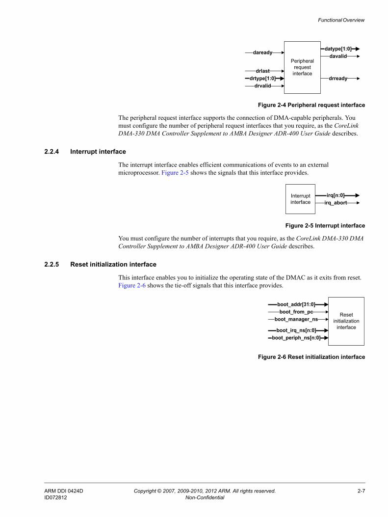
2.2.3 Peripheral request interfaces
Figure 2-4 on page 2-7 shows the signals that a single peripheral request interface provides.
Table 2-1 AXI characteristics for a DMA transfer
Access type AxPROT AxLEN AxBURST AxSIZE AxCACHE
DMA channel load See Channel Control Registers on page 3-25
DMA channel store See Channel Control Registers on page 3-25
DMA managerinstruction fetch
Privileged.Secure state from DNSa bit.Instruction.
See ARLEN and ARSIZE for instruction fetches
INCR
See ARLEN and ARSIZE for instruction fetches
Cacheablewrite-through,allocate onreads only.
DMA channelinstruction fetch
Privileged.Secure state from CNSb bit.Instruction.
a. The DSR Register contains the DNS bit. See DMA Manager Status Register on page 3-11.b. The CSRn Register contains the CNS bit for DMA channel n. See Channel Status Registers on page 3-21.
ARM DDI 0424D Copyright © 2007, 2009-2010, 2012 ARM. All rights reserved. 2-6ID072812 Non-Confidential
Functional Overview
Figure 2-4 Peripheral request interface
The peripheral request interface supports the connection of DMA-capable peripherals. You must configure the number of peripheral request interfaces that you require, as the CoreLink DMA-330 DMA Controller Supplement to AMBA Designer ADR-400 User Guide describes.
2.2.4 Interrupt interface
The interrupt interface enables efficient communications of events to an external microprocessor. Figure 2-5 shows the signals that this interface provides.
Figure 2-5 Interrupt interface
You must configure the number of interrupts that you require, as the CoreLink DMA-330 DMA Controller Supplement to AMBA Designer ADR-400 User Guide describes.
2.2.5 Reset initialization interface
This interface enables you to initialize the operating state of the DMAC as it exits from reset. Figure 2-6 shows the tie-off signals that this interface provides.
Figure 2-6 Reset initialization interface
Peripheral request interface
daready
drtype[1:0]drlast
drvalid
datype[1:0]davalid
drready
Interrupt interface
irq[n:0]irq_abort
Reset initialization
interface
boot_from_pcboot_addr[31:0]
boot_manager_ns
boot_irq_ns[n:0]boot_periph_ns[n:0]
ARM DDI 0424D Copyright © 2007, 2009-2010, 2012 ARM. All rights reserved. 2-7ID072812 Non-Confidential

Functional Overview
2.3 Operating statesFigure 2-7 shows the operating states for the DMA manager thread and DMA channel threads. The DMAC provides a separate state machine for each thread.
Figure 2-7 Thread operating states
Note In Figure 2-7, the DMAC permits that:• Only DMA channel threads can use states in bold italics.• Arcs with no letter designator indicate state transitions for the DMA manager and DMA
channel threads, otherwise use is restricted as follows:C DMA channel threads only.M DMA manager thread only.
• states within the dotted line can transition to the Faulting completing, Faulting, or Killing states.
After the DMAC exits from reset, it sets all DMA channel threads to the Stopped state, and the status of boot_from_pc controls the DMA manager thread state:
boot_from_pc is LOW DMA manager thread moves to the Stopped state.
boot_from_pc is HIGH DMA manager thread moves to the Executing state.
The following sections describe the states:• Stopped on page 2-9.• Executing on page 2-9.• Cache miss on page 2-10.
Executing
Cache miss
Updating PC
Waiting for event
At barrier
Waiting for peripheral
CompletingFaulting
completing
Faulting Stopped
C
C
CC
C
C
C
C
M
Killing
C
C
C
ARM DDI 0424D Copyright © 2007, 2009-2010, 2012 ARM. All rights reserved. 2-8ID072812 Non-Confidential

Functional Overview
• Updating PC on page 2-10.• Waiting for event on page 2-10.• At barrier on page 2-10.• Waiting for peripheral on page 2-10.• Faulting completing on page 2-10.• Faulting on page 2-10.• Killing on page 2-10.• Completing on page 2-10.
2.3.1 Stopped
The thread has an invalid PC and it is not fetching instructions. Depending on the thread type, you can cause the thread to move to the Executing state by:
DMA manager thread With boot_from_pc HIGH and aresetn LOW then the DMA manager thread moves to the Executing state after aresetn goes HIGH.
DMA channel thread Programming the DMA manager thread to execute DMAGO for a DMA channel thread in the Stopped state.
2.3.2 Executing
The thread has a valid PC and therefore the DMAC includes the thread when it arbitrates. The thread can then change to one of the following states under the following conditions:
Stopped When the DMA manager thread executes DMAEND.
Cache miss When the instruction cache does not contain the next instruction for either the DMA manager thread or the DMA channel thread.
Updating PC When the DMAC calculates the address of the next access in the cache.
Waiting for event When a thread executes DMAWFE.
At barrier When a DMA channel thread either:• Executes DMARMB, DMAWMB, or DMAFLUSHP.• Updates control registers that affect alignment, see Updating DMA
channel control registers during a DMA cycle on page 2-36.
Waiting for peripheral When a DMA channel thread executes DMAWFP.
Killing When a DMA channel thread executes DMAKILL.
Faulting completing For a DMA channel thread when either:• The thread executes an undefined or invalid instruction.• An AXI bus error occurs during an instruction fetch or data transfer.
Faulting For the DMA manager thread when either:• The thread executes an undefined or invalid instruction.• An AXI bus error occurs during an instruction fetch.For a DMA channel thread when a watchdog timeout abort occurs.
ARM DDI 0424D Copyright © 2007, 2009-2010, 2012 ARM. All rights reserved. 2-9ID072812 Non-Confidential

Functional Overview
Completing When a DMA channel thread executes DMAEND.
2.3.3 Cache miss
The thread is stalled and the DMAC is performing a cache line fill. After it completes the cache fill, the thread returns to the Executing state.
2.3.4 Updating PC
The DMAC is calculating the address of the next access in the cache. After it calculates the PC, the thread returns to the Executing state.
2.3.5 Waiting for event
The thread is stalled and is waiting for the DMAC to execute DMASEV using the corresponding event number. After the corresponding event occurs, the thread returns to the Executing state.
2.3.6 At barrier
A DMA channel thread is stalled and the DMAC is waiting for transactions on the AXI bus to complete. After the AXI transactions complete, the thread returns to the Executing state.
2.3.7 Waiting for peripheral
A DMA channel thread is stalled and the DMAC is waiting for the peripheral to provide the requested data. After the peripheral provides the data, the thread returns to the Executing state.
2.3.8 Faulting completing
A DMA channel thread is waiting for the AXI master interface to signal that the outstanding load or store transactions are complete. After the transactions complete, the thread moves to the Faulting state.
2.3.9 Faulting
The thread is stalled indefinitely. The thread moves to the Stopped state when you use the DBGCMD Register to instruct the DMAC to execute DMAKILL for that thread. See Debug Command Register on page 3-31.
2.3.10 Killing
A DMA channel thread is waiting for the AXI master interface to signal that the outstanding load or store transactions are complete. After the transactions complete, the thread moves to the Stopped state.
2.3.11 Completing
A DMA channel thread is waiting for the AXI master interface to signal that the outstanding load or store transactions are complete. After the transactions complete, the thread moves to the Stopped state.
ARM DDI 0424D Copyright © 2007, 2009-2010, 2012 ARM. All rights reserved. 2-10ID072812 Non-Confidential
Functional Overview
2.4 Initializing the DMACThe DMAC provides several tie-off signals that initialize its operating state when it exits from reset. The following sections describe the initialization of the tie-offs:• How to set the security state of the DMA manager.• How to set the location of the first instruction for the DMAC to execute.• How to set the security state for the interrupt outputs on page 2-12.• How to set the security state for a peripheral request interface on page 2-12.
2.4.1 How to set the security state of the DMA manager
The boot_manager_ns signal is the only method to set the security state of the DMA manager. When the DMAC exits from reset, it reads the status of boot_manager_ns and sets the security of the DMA manager as Table A-11 on page A-9 shows.
Note When set, the security state remains constant until a state transition on aresetn resets the DMAC.
See DMA manager thread is in the Secure state on page 2-29 and DMA manager thread is in the Non-secure state on page 2-29 for a description of how the security state of the DMA manager affects how the DMAC operates.
2.4.2 How to set the location of the first instruction for the DMAC to execute
After the DMAC exits from reset, the status of the boot_from_pc signal controls if the DMAC either:
• Enters the Executing state and:— Updates the DPC Register using the address that boot_addr[31:0] provides, see
DMA Program Counter Register on page 3-12.— Fetches and executes the instruction from the address that the DPC Register
contains.
Note — You must ensure that the state of the boot_addr[31:0] bus, points to a region in
system memory that contains the start address for the DMAC boot program.— If you set boot_manager_ns so that the DMA manager operates in the Non-secure
state, the boot program must reside in a non-secure region of memory.
• Enters the Stopped state. You must then provide the first instruction to the DMAC by using one of the slave APB interfaces.
Note If boot_manager_ns was LOW when the DMAC exited reset then to send instructions
you must use the secure APB interface, see Security usage on page 2-29.
See Table A-11 on page A-9 for information about boot_from_pc.
ARM DDI 0424D Copyright © 2007, 2009-2010, 2012 ARM. All rights reserved. 2-11ID072812 Non-Confidential

Functional Overview
2.4.3 How to set the security state for the interrupt outputs
The DMAC provides the boot_irq_ns[x:0] signals to enable you to assign each irq[x] signal to a security state as Table A-12 on page A-9 shows.
Note When set, the security state of each irq[x] remains constant until a state transition on aresetn resets the DMAC.
See Security usage on page 2-29 for a description of how the security state of the irq[x] signals affects how the DMAC executes the DMAWFE and DMASEV instructions.
2.4.4 How to set the security state for a peripheral request interface
The DMAC provides the boot_periph_ns[x:0] signals to enable you to assign each peripheral request interface to a security state as Table A-12 on page A-9 shows.
Note When set, the security state of each peripheral request interface remains constant until a state transition on aresetn resets the DMAC.
See Security usage on page 2-29 for how the security state of the peripheral request interfaces affects how a DMA channel thread executes the DMAWFP, DMALDP, DMASTP, or DMAFLUSHP instructions.
ARM DDI 0424D Copyright © 2007, 2009-2010, 2012 ARM. All rights reserved. 2-12ID072812 Non-Confidential

Functional Overview
2.5 Using the APB slave interfacesThe APB slave interface connects the DMAC to the APB and enables a microprocessor to access the registers that Chapter 3 Programmers Model describes. Using these registers, a microprocessor can:• Access the status of the DMA manager thread.• Access the status of the DMA channel threads.• Enable or clear interrupts.• Enable events.• Issue an instruction for the DMAC to execute by programming the following debug
registers:— DBGCMD Register, see Debug Command Register on page 3-31.— DBGINST0 Register, see Debug Instruction-0 Register on page 3-32.— DBGINST1 Register, see Debug Instruction-1 Register on page 3-33.
2.5.1 Issuing instructions to the DMAC using an APB interface
When the DMAC is operating in real-time, you can only issue the following limited subset of instructions:
DMAGO Starts a DMA transaction using a DMA channel that you specify.
DMASEV Signals the occurrence of an event, or interrupt, using an event number that you specify.
DMAKILL Terminates a thread.
You must ensure that you use the appropriate APB interface, depending on the security state in which the boot_manager_ns initializes the DMAC to operate. For example, if the DMAC is in the Secure state, you must issue the instruction using the secure APB interface, otherwise the DMAC ignores the instruction. You can use the secure APB interface, or the non-secure APB interface, to start or restart a DMA channel when the DMAC is in the Non-secure state.
Note Before you can issue instructions using the debug instruction registers or the DBGCMD Register, you must read the DBGSTATUS Register to ensure that debug is idle, otherwise the DMAC ignores the instructions. See Debug Command Register on page 3-31 and Debug Status Register on page 3-30.
When the DMAC receives an instruction from an APB slave interface, it can take several clock cycles before it can process the instruction, for example, if the pipeline is busy processing another instruction.
Note Prior to issuing DMAGO, you must ensure that the system memory contains a suitable program for the DMAC to execute, starting at the address that the DMAGO specifies.
Example 2-1 on page 2-14 shows the necessary steps to start a DMA channel thread using the debug instruction registers.
ARM DDI 0424D Copyright © 2007, 2009-2010, 2012 ARM. All rights reserved. 2-13ID072812 Non-Confidential

Functional Overview
Example 2-1 Using DMAGO with the debug instruction registers
1. Create a program for the DMA channel.
2. Store the program in a region of system memory.
Use one of the APB interfaces on the DMAC to program a DMAGO instruction as follows:
3. Poll the DBGSTATUS Register to ensure that debug is idle, that is, the dbgstatus bit is 0. See Debug Status Register on page 3-30.
4. Write to the DBGINST0 Register and enter the:• Instruction byte 0 encoding for DMAGO.• Instruction byte 1 encoding for DMAGO.• Debug thread bit to 0. This selects the DMA manager thread. See Debug
Instruction-0 Register on page 3-32.
5. Write to the DBGINST1 Register with the DMAGO instruction byte [5:2] data, see Debug Instruction-1 Register on page 3-33. You must set these four bytes to the address of the first instruction in the program, that was written to system memory in step 2.
Instruct the DMAC to execute the instruction that the debug instruction registers contain by:
6. Writing zero to the DBGCMD Register. The DMAC starts the DMA channel thread and sets the dbgstatus bit to 1. See Debug Command Register on page 3-31.After the DMAC completes execution of the instruction, it clears the dbgstatus bit to 0.
ARM DDI 0424D Copyright © 2007, 2009-2010, 2012 ARM. All rights reserved. 2-14ID072812 Non-Confidential

Functional Overview
2.6 Peripheral request interfaceFigure 2-8 shows that the peripheral request interface consists of a peripheral request bus and a DMAC acknowledge bus that use the prefixes:dr The peripheral request bus.da The DMAC acknowledge bus.
Figure 2-8 Request and acknowledge buses on the peripheral request interface
Both buses use the valid and ready handshake that the AXI protocol describes. For more information on the handshake process, see the AMBA AXI and ACE Protocol Specification.
The peripheral uses drtype[1:0] to either:• Request a single transfer.• Request a burst transfer.• Acknowledge a flush request.
The peripheral uses drlast to notify the DMAC that the request on drtype[1:0] is the last request of the DMA transfer sequence. drlast is transferred at the same time as drtype[1:0].
The DMAC uses datype[1:0] to either:• Signal when it completes the requested single transfer.• Signal when it completes the requested burst transfer.• Issue a flush request.
Note If you configure the DMAC to provide more than one peripheral request interface, each interface is assigned a unique identifier, _<x> where <x> represents the number of the interface. See Peripheral request interface on page A-7 for information about how the identifier is appended to the signal name.
The following sections describe:• Mapping to a DMA channel on page 2-16.• Handshake rules on page 2-16.• Request acceptance capability configuration on page 2-16.• Peripheral length management on page 2-17.• DMAC length management on page 2-19.• Peripheral request interface timing diagrams on page 2-21.
DMACPeripheral
drvaliddrtype[1:0]drlast
daready
davaliddatype[1:0]
drready Peripheralrequestinterface
ARM DDI 0424D Copyright © 2007, 2009-2010, 2012 ARM. All rights reserved. 2-15ID072812 Non-Confidential

Functional Overview
2.6.1 Mapping to a DMA channel
The DMAC enables you to assign a peripheral request interface to any of the DMA channels. When a DMA channel thread executes DMAWFP, the value programmed in the peripheral [4:0] field specifies the peripheral associated with that DMA channel. See DMAWFP on page 4-18.
2.6.2 Handshake rules
The DMAC uses the DMA handshake rules that Table 2-2 shows, when a DMA channel thread is active, that is, not in the Stopped state. See Peripheral request interface timing diagrams on page 2-21 for more information.
2.6.3 Request acceptance capability configuration
During configuration of the DMAC, you can set the number of simultaneous active requests that a DMAC is able to accept, for each peripheral request interface. An active request is where the DMAC has not started the requested AXI data transfers.
For each peripheral interface, the DMAC has a request FIFO that it uses to capture the requests from a peripheral. The depth of a FIFO depends on the number of simultaneous active requests that the corresponding peripheral request interface is configured to support. To store the state of an active request from the peripheral, the request FIFO uses two bits to store the state of:
• drtype_<x>[0]. Indicates the request type, burst or single.
• drlast_<x>. Indicates if the peripheral is requesting the last data transfer of the DMA transfer.
When a request FIFO is full then the DMAC sets the corresponding drready_<x> LOW to signal that the DMAC cannot accept any requests sent from the peripheral.
Table 2-2 Handshake rules
Rule Descriptiona
1 drvalid can change from LOW to HIGH on any aclk cycle, but it must only change from HIGH to LOW when drready is HIGH.
2 drtype can only change when either:• drready is HIGH.• drvalid is LOW.
3 drlast can only change when either:• drready is HIGH.• drvalid is LOW.
4 davalid can change from LOW to HIGH on any aclk cycle, but it must only change from HIGH to LOW when daready is HIGH.
5 datype can only change when either:• daready is HIGH.• davalid is LOW.
a. All signals are only permitted to change state when aclk changes state.
ARM DDI 0424D Copyright © 2007, 2009-2010, 2012 ARM. All rights reserved. 2-16ID072812 Non-Confidential

Functional Overview
2.6.4 Peripheral length management
The peripheral request interface enables a peripheral to control the quantity of data that a DMA cycle contains, without the DMAC being aware of how many data transfers it contains. The peripheral controls the DMA cycle by using:• drtype[1:0] to select a single or burst transfer.• drlast to notify the DMAC when it commences the final request in the current series.
When the DMAC executes a DMAWFP periph instruction, it halts execution of the thread and waits for the peripheral to send a request. When the peripheral sends the request, the DMAC sets the state of the request flags depending on the state of the following signals:
drtype_<x>[1:0] The DMAC sets the state of the request_type flag:drtype_<x>[1:0]=0b00
request_type<x> = Single.drtype_<x>[1:0]=0b01
request_type<x> = Burst.
drlast_<x> The DMAC sets the state of the request_last flag:drlast_<x>=0 request_last<x> = 0.drlast_<x>=1 request_last<x> = 1.
Note If the DMAC executes a DMAWFP single or DMAWFP burst instruction then the DMAC sets:• The request_type<x> flag to Single or Burst, respectively.• The request_last<x> flag to 0.
DMALPFE is an assembler directive that forces the associated DMALPEND instruction to have its nf bit set to 0. This creates a program loop that does not use a loop counter to terminate the loop. The DMAC exits the loop when the request_last flag is set to 1.
The DMAC conditionally executes the following instructions, depending on the state of the request_type and request_last flags:
DMALD, DMAST, DMALPEND When these instructions use the optional B|S suffix then the DMAC executes a DMANOP if the request_type flag does not match.
DMALDP<B|S>, DMASTP<B|S> The DMAC executes a DMANOP if the request_type flag does not match the B|S suffix.
DMALPEND When the nf bit is 0, the DMAC executes a DMANOP if the request_last flag is set.
Use the DMALDB, DMALDPB, DMASTB and DMASTPB instructions if you require the DMAC to issue a burst transfer when the DMAC receives a burst request, that is, drtype_<x>[1:0] = 0b01. The values in the CCRn Register control the amount of data that the DMAC transfers, see Channel Control Registers on page 3-25.
Use the DMALDS, DMALDPS, DMASTS and DMASTPS instructions if you require the DMAC to issue a single transfer when the DMAC receives a single request, that is, drtype_<x>[1:0] = 0b00. The DMAC ignores the value of the src_burst_len and dst_burst_len fields in the CCRn Register and sets the arlen[3:0] or awlen[3:0] buses to 0x0.
ARM DDI 0424D Copyright © 2007, 2009-2010, 2012 ARM. All rights reserved. 2-17ID072812 Non-Confidential

Functional Overview
Example program for peripheral length management
Example 2-2 shows a DMAC program that transfers 64 words from memory to peripheral zero, when the peripheral sends a burst request, that is, drtype_<x>[1:0] = 0b01. When the peripheral sends a single request, that is, drtype_<x>[1:0] = 0b00, then the DMAC program transfers one word from memory to peripheral zero.
To transfer the 64 words, the program instructs the DMAC to perform 16 AXI transfers. Each AXI transfer consists of a 4-beat burst (SB=4, DB=4), each beat of which moves a word of data (SS=32, DS=32).
Example 2-2 Peripheral length management program
# Set up for burst transfers (4-beat burst, so SB4 and DB4), (word data width, so SS32 and DS32)DMAMOV CCR SB4 SS32 DB4 DS32DMAMOV SAR ...DMAMOV DAR ...
# Initialize peripheral ‘0’DMAFLUSHP P0
# Perform peripheral transfers# Outer loop - DMAC responds to peripheral requests until peripheral sets drlast_0 = 1DMALPFE
# Wait for request, DMAC sets request_type0 flag depending on the request type it receivesDMAWFP 0, periph
# Set up loop for burst request: first 15 of 16 sets of transactions# Note: B suffix - conditionally executed only if request_type0 flag = BurstDMALP 15
DMALDBDMASTB
# Only loop back if servicing a burst, otherwise treat as a NOPDMALPENDB
# Perform final transaction (16 of 16). Send the peripheral acknowledgement of burst request completionDMALDBDMASTPB P0
# Perform transaction if the peripheral signals a single request# Note: S suffix - conditionally executed only if request_type0 flag = SingleDMALDSDMASTPS P0
# Exit loop if DMAC receives the last request, that is, drlast_0 = 1DMALPEND
DMAEND
In Example 2-2, the program shows the use of the:
• DMAWFP periph instruction. The DMAC waits for either a burst or single request from the peripheral.
• DMASTPB and DMASTPS instructions. The DMAC informs the peripheral when a transfer is complete.
ARM DDI 0424D Copyright © 2007, 2009-2010, 2012 ARM. All rights reserved. 2-18ID072812 Non-Confidential

Functional Overview
2.6.5 DMAC length management
DMAC length management is when the DMAC controls the total amount of data to transfer. The peripheral uses the peripheral request interface to notify the DMAC when it requires the DMAC to transfer data to or from the peripheral. The DMA channel thread controls how the DMAC responds to the peripheral requests.
The following constraints apply to DMAC length management:
• The total quantity of data for all the single requests from a peripheral must be less than the quantity of data for a burst request for that peripheral.
Note The CCRn Register controls how much data is transferred for a burst request and a single
request. ARM recommends that you do not update a CCRn Register when a transfer is in progress for channel n. See Channel Control Registers on page 3-25.
• When the peripheral sends a burst request then the peripheral must not send a single request until the DMAC acknowledges that the burst request is complete.
Use the DMAWFP single instruction when you require the program thread to halt execution until the peripheral request interface receives any request type.
If the head entry in the request FIFO is of request type:
Single The DMAC pops the entry from the FIFO and continues program execution.
Burst The DMAC leaves the entry in the FIFO and continues program execution.
Note The burst request entry remains in the request FIFO until the DMAC executes a
DMAWFP burst instruction or a DMAFLUSHP instruction.
Use the DMAWFP burst instruction when you require the program thread to halt execution until the peripheral request interface receives a burst request. If the head entry in the request FIFO is of request type:
Single The DMAC removes the entry from the FIFO and program execution remains halted.
Burst The DMAC pops the entry from the FIFO and continues program execution.
Use the DMALDP instruction when you require the DMAC to send an acknowledgement to the peripheral when it completes the AXI read transfers. Similarly, use the DMASTP instruction when you require the DMAC to send an acknowledgement to the peripheral when it completes the AXI write transfers. The DMAC uses the datype_<x>[1:0] bus to signal a transfer acknowledgement to peripheral <x>.
Note The DMAC sends an acknowledgement for a read transaction when rvalid and rlast are HIGH and for a write transaction when bvalid is HIGH. If your system is able to buffer AXI write transfers then it might be possible for the DMAC to send an acknowledgement to the peripheral but the transfer of write data to the end destination is still in progress.
Use the DMAFLUSHP instruction to reset the request FIFO for the peripheral request interface. After the DMAC executes DMAFLUSHP, it ignores peripheral requests until the peripheral acknowledges the flush request. This enables the DMAC and peripheral to synchronize with each other.
ARM DDI 0424D Copyright © 2007, 2009-2010, 2012 ARM. All rights reserved. 2-19ID072812 Non-Confidential

Functional Overview
Example program for DMAC length management
Example 2-3 shows a DMAC program that can transfer 1027 words when a peripheral signals 16 consecutive burst requests and three consecutive single requests.
Example 2-3 DMAC length management program
# Set up for AXI burst transfer (4-beat burst, so SB4 and DB4), (word data width, so SS32 and DS32)DMAMOV CCR SB4 SS32 DB4 DS32DMAMOV SAR ...DMAMOV DAR ...
# Initialize peripheral '0'DMAFLUSHP P0
# Perform peripheral transfers# Burst request loop to transfer 1024 wordsDMALP 16
# Wait for the peripheral to signal a burst request. DMAC transfers 64 words for each burst requestDMAWFP 0, burst
# Set up loop for burst request: first 15 of 16 sets of transactionsDMALP 15
DMALDDMAST
DMALPEND
# Perform final transaction (16 of 16). Send the peripheral acknowledgement of burst request completionDMALDDMASTPB 0
# Finish burst loopDMALPEND
# Set up for AXI single transfer (word data width, so SS32 and DS32)DMAMOV CCR SB1 SS32 DB1 DS32
# Single request loop to transfer 3 wordsDMALP 3
# Wait for the peripheral to signal a single request. DMAC to transfer one wordDMAWFP 0, single
# Perform transaction for single request and send completion acknowledgement to the peripheralDMALDSDMASTPS P0
# Finish single loopDMALPEND
# Flush the peripheral, in case the single transfers were in response to a burst requestDMAFLUSHP 0
DMAEND
ARM DDI 0424D Copyright © 2007, 2009-2010, 2012 ARM. All rights reserved. 2-20ID072812 Non-Confidential

Functional Overview
2.6.6 Peripheral request interface timing diagrams
The following sections provide examples of the functional operation of the peripheral request interface using the rules that Handshake rules on page 2-16 describe:• Burst request.• Single and burst request.• DMAC performs single transfers for a burst request on page 2-22.
Burst request
Figure 2-9 shows the DMA request timing when a peripheral requests a burst transfer.
Figure 2-9 Burst request signaling
In Figure 2-9:
T1 The DMAC detects a request for a burst transfer.
T3 - T6 The DMAC performs a burst transfer.
T7 The DMAC sets davalid HIGH and sets datype[1:0] to indicate that the burst transfer is complete.
Single and burst request
Figure 2-10 shows the DMA request timing when a peripheral requests a single and a burst transfer.
Figure 2-10 Single and burst request signaling
drvalid
aclk
drtype[1:0] Burst
drready
davalid
datype[1:0]
daready
Ack
Data burstDMA activity onthe AXI data bus
T0 T1 T2 T3 T4 T5 T6 T7 T8 T9
drvalid
aclk
drtype[1:0] Single
drready
davalid
datype[1:0]
daready
Ack
Data burstDMA activity onthe AXI data bus
Burst
T0 T1 T2 T3 T4 T5 T6 T7 T8 T9 T10 T11 T12 T13
ARM DDI 0424D Copyright © 2007, 2009-2010, 2012 ARM. All rights reserved. 2-21ID072812 Non-Confidential

Functional Overview
In Figure 2-10 on page 2-21:
T1 The DMAC detects a request for a single transfer.
T3 The DMAC ignores the single transfer request because the DMA channel thread had executed a DMAWFP burst instruction. See DMAWFP on page 4-18.
T5 The DMAC detects a request for a burst transfer.
T7 - T10 The DMAC performs a burst transfer.
T11 The DMAC sets davalid HIGH and sets datype[1:0] to indicate that the burst transfer is complete.
DMAC performs single transfers for a burst request
Figure 2-11 shows the DMA request timing when a peripheral requests a burst transfer, but the DMAC has insufficient data remaining in the MFIFO to generate a burst and therefore completes the request using single transfers.
Figure 2-11 Single transfers for a burst request
In Figure 2-11:
T1 The DMAC detects a request for a burst transfer.
T3 The MFIFO contains insufficient data for the DMAC to generate a burst transfer and therefore, the DMAC performs a single transfer.
T4 The DMAC signals davalid and datype[1:0] to indicate completion of a single transfer.
T5 - T10 The DMAC performs the remaining three single transfers.
T11 The DMAC signals davalid and datype[1:0] to request the peripheral to flush the contents of any control registers that are associated with the current DMA cycle.
T12 The peripheral signals drvalid and drtype[1:0] to acknowledge the flush request.
T0
drvalid
aclk
drtype[1:0] Burst
drready
davalid
datype[1:0]
daready
Ack
DataDMA activity onthe AXI data bus
Ack Ack Ack Flush
Flush
Data Data Data
T1 T2 T3 T4 T5 T6 T7 T8 T9 T10 T11 T12 T13
ARM DDI 0424D Copyright © 2007, 2009-2010, 2012 ARM. All rights reserved. 2-22ID072812 Non-Confidential

Functional Overview
2.7 Using events and interruptsThe number of events and interrupts that the DMAC can support is configurable. When the configured number of event-interrupt resources is set then you must program the INTEN Register to control if each event-interrupt resource is either an event or an interrupt. See Interrupt Enable Register on page 3-13.
When the DMAC executes a DMASEV instruction it modifies the event-interrupt resource that you specify. If the INTEN Register sets the event-interrupt resource to be an:
Event The DMAC generates an event for the specified event-interrupt resource. When the DMAC executes a DMAWFE instruction for the same event-interrupt resource then it clears the event.
Interrupt The DMAC sets irq<event_num> HIGH, where event_num is the number of the specified event-resource. To clear the interrupt you must write to the INTCLR Register, see Interrupt Clear Register on page 3-15.
Therefore, if you require a DMAC to be able to signal two interrupt requests and generate five events then the DMAC must be configured to support seven event-interrupt resources. In this example, the DMAC provides seven interrupt signals, irq[6:0], and therefore five of these signals are not used.
Note See the CoreLink DMA-330 DMA Controller Supplement to AMBA Designer ADR-400 User Guide for information about how to configure the number of events or interrupts that a DMAC supports.
This section describes:• Using an event to restart DMA channels.• Interrupting a microprocessor on page 2-24.
2.7.1 Using an event to restart DMA channels
When you program the INTEN Register to generate an event, you can use the DMASEV and DMAWFE instructions to restart one or more DMA channels. See Interrupt Enable Register on page 3-13.
The following sections describe the DMAC behavior when the:• DMAC executes DMAWFE before DMASEV.• DMAC executes DMASEV before DMAWFE on page 2-24.
DMAC executes DMAWFE before DMASEV
To restart a single DMA channel:
1. The first DMA channel executes DMAWFE and then stalls while it waits for the event to occur.
2. The other DMA channel executes DMASEV using the same event number. This generates an event, and the first DMA channel restarts. The DMAC clears the event, one aclk cycle after it executes DMASEV.
You can program multiple channels to wait for the same event. For example, if four DMA channels have all executed DMAWFE for event 12, then when another DMA channel executes DMASEV for event 12, the four DMA channels all restart at the same time. The DMAC clears the event, one clock cycle after it executes DMASEV.
ARM DDI 0424D Copyright © 2007, 2009-2010, 2012 ARM. All rights reserved. 2-23ID072812 Non-Confidential

Functional Overview
DMAC executes DMASEV before DMAWFE
If the DMAC executes DMASEV before another channel executes DMAWFE then the event remains pending until the DMAC executes DMAWFE. When the DMAC executes DMAWFE it halts execution for one aclk cycle, clears the event and then continues execution of the channel thread.
For example, if the DMAC executes DMASEV 6 and none of the other threads have executed DMAWFE 6 then the event remains pending. If the DMAC executes DMAWFE 6 instruction for channel 4 and then executes DMAWFE 6 instruction for channel 3, then:
1. The DMAC halts execution of the channel 4 thread for one aclk cycle.
2. The DMAC clears event 6.
3. The DMAC resumes execution of the channel 4 thread.
4. The DMAC halts execution of the channel 3 thread and the thread stalls while it waits for the next occurrence of event 6.
2.7.2 Interrupting a microprocessor
The DMAC provides the irq[x] signals for use as active-high level-sensitive interrupts to external microprocessors. When you program the INTEN Register to generate an interrupt, after the DMAC executes DMASEV, it sets the corresponding irq[x] HIGH. See Interrupt Enable Register on page 3-13.
An external microprocessor can clear the interrupt by writing to the Interrupt Clear Register on page 3-15.
Note Executing DMAWFE does not clear an interrupt.
If you use the DMASEV instruction to notify a microprocessor when the DMAC completes a DMALD or DMAST instruction then ARM recommends that you insert a memory barrier instruction before the DMASEV. Otherwise the DMAC might signal an interrupt before the AXI transfers complete. For example:
DMALDDMAST
# Issue a write memory barrier# Wait for the AXI write transfer to complete before the DMAC can send an interrupt
DMAWMB
# The DMAC sends the interruptDMASEV
ARM DDI 0424D Copyright © 2007, 2009-2010, 2012 ARM. All rights reserved. 2-24ID072812 Non-Confidential

Functional Overview
2.8 AbortsThis section describes:• Abort types.• Abort sources.• Watchdog abort on page 2-26.• Abort handling on page 2-26.
2.8.1 Abort types
An abort can be classified as either precise or imprecise, depending on whether the DMAC provides an abort handler with the precise state of the DMAC when the abort occurs. If an abort is:
Precise The DMAC updates the PC Register with the address of the instruction that created the abort. See Channel Program Counter Registers on page 3-23.
Imprecise The PC Register might contain the address of an instruction that did not cause the abort to occur. See Channel Program Counter Registers on page 3-23.
2.8.2 Abort sources
The DMAC signals a precise abort under the following conditions:
• A DMA channel thread in the Non-secure state attempts to program its CCRn Register and generate a secure AXI transaction. See Channel Control Registers on page 3-25.
• A DMA channel thread in the Non-secure state executes DMAWFE or DMASEV for an event that is set as secure. The boot_irq_ns tie-offs initialize the security state for an event.
Note For each event, the INTEN Register controls if the DMAC generates an event or signals
an interrupt. See Interrupt Enable Register on page 3-13.
• A DMA channel thread attempts to execute DMAST but the DMAC calculates that when it eventually performs the store, the MFIFO contains insufficient data to enable it to complete the store.
• A DMA channel thread in the Non-secure state executes DMAWFP, DMALDP, DMASTP, or DMAFLUSHP for a peripheral request interface that is set as secure. The boot_periph_ns tie-offs initialize the security state for a peripheral request interface.
• A DMA manager thread in the Non-secure state executes DMAGO to attempt to start a secure DMA channel thread.
• The DMAC receives an ERROR response on the AXI master interface when it performs an instruction fetch.
• A thread executes an undefined instruction.
• A thread executes an instruction with an operand that is invalid for the configuration of the DMAC.
Note When the DMAC signals a precise abort, the instruction that triggers the abort is not executed. Instead, the DMAC executes a DMANOP.
ARM DDI 0424D Copyright © 2007, 2009-2010, 2012 ARM. All rights reserved. 2-25ID072812 Non-Confidential

Functional Overview
The DMAC signals an imprecise abort under the following conditions:
• The DMAC receives an ERROR response on the AXI master interface when it performs a data load.
• The DMAC receives an ERROR response on the AXI master interface when it performs a data store.
• A DMA channel thread executes DMALD or DMAST, and the MFIFO is too small to hold the required amount of data.
• A DMA channel thread executes DMAST but the thread has not executed sufficient DMALD instructions.
• A DMA channel thread locks up because of resource starvation, and this causes the internal watchdog timer to time out.
2.8.3 Watchdog abort
The DMAC can lock up if one or more DMA channel programs are running and the MFIFO is too small to satisfy the storage requirements of the DMA programs.
The DMAC contains logic to prevent it from remaining in a state where it is unable to complete a DMA transfer.
The DMAC detects a lock up when all of the following conditions occur:
• Load queue is empty.
• Store queue is empty.
• All of the running channels are prevented from executing a DMALD instruction either because the MFIFO does not have sufficient free space or another channel owns the load-lock.
When the DMAC detects a lockup it signals an interrupt and can also abort the contributing channels. The DMAC behavior depends on the state of the wd_irq_only bit in the WD Register. If:
wd_irq_only=0 The DMAC aborts all of the contributing DMA channels and sets irq_abort HIGH.
wd_irq_only=1 The DMAC sets irq_abort HIGH.
For more information see Resource sharing between DMA channels on page 2-37 and Watchdog Register on page 3-40.
2.8.4 Abort handling
The architecture of the DMAC is not designed to recover from an abort and you must therefore use an external agent, such as a microprocessor, to terminate a thread when an abort occurs. Figure 2-12 on page 2-27 shows the operating states for the DMA channel and DMA manager threads after an abort occurs.
ARM DDI 0424D Copyright © 2007, 2009-2010, 2012 ARM. All rights reserved. 2-26ID072812 Non-Confidential

Functional Overview
Figure 2-12 Abort process
After an abort occurs, the action the DMAC takes depends on the thread type:
DMA channel thread The thread immediately moves to the Faulting completing state. In this state, the DMAC:• Sets irq_abort HIGH.• Stops executing instructions for the DMA channel.• Invalidates all cache entries for the DMA channel.• Updates the CPCn Register to contain the address of the aborted instruction
provided that the abort was precise, see Channel Program Counter Registers on page 3-23.
• Does not generate AXI accesses for any instructions remaining in the read queue and write queue.
• permits currently active AXI transactions to complete.
Note After the transactions for the DMA channel complete, the thread moves to
the Faulting state.
DMA channel thread DMA manager thread
Executing program thread
Has an abort occurred?
Yes
No
ActiveAXI transactions
complete?No
DMAKILLexecuted?
Yes
No
Executing program thread
Has an abort occurred?
No
Thread moves to the Faulting completing state
Thread moves to the Faulting state
Thread moves to the Stopped state
Yes
Yes
ARM DDI 0424D Copyright © 2007, 2009-2010, 2012 ARM. All rights reserved. 2-27ID072812 Non-Confidential

Functional Overview
DMA manager thread The thread immediately moves to the Faulting state and the DMAC sets irq_abort HIGH.
The external agent can respond to the assertion of irq_abort by:
• Reading the status of the FSRD Register to determine if the DMA manager is Faulting. In the Faulting state, the FSRD Register provides the cause of the abort. See Fault Status DMA Manager Register on page 3-16.
• Reading the status of the FSRC Register to determine if a DMA channel is Faulting. In the Faulting state, the FSRC Register provides the cause of the abort. See Fault Status DMA Channel Register on page 3-16.
To enable a thread in the Faulting state to move to the Stopped state, the external agent must:
1. Program the DBGINST0 Register with the encoding for the DMAKILL instruction. See Debug Instruction-0 Register on page 3-32.
2. Write to the DBGCMD Register. See Debug Command Register on page 3-31.
Note If the aborted thread is secure, you must use the secure APB interface to update these
registers.
After a thread in the Faulting state executes DMAKILL, it moves to the Stopped state.
ARM DDI 0424D Copyright © 2007, 2009-2010, 2012 ARM. All rights reserved. 2-28ID072812 Non-Confidential

Functional Overview
2.9 Security usageWhen the DMAC exits from reset, the status of the configuration signals that Tie-off signals on page A-9 describes, configures the security for:
DMA manager thread The DNS bit in the DSR Register returns the security state of the DMA manager thread. See DMA Manager Status Register on page 3-11.
Events and interrupts The INS bit in the CR3 Register returns the security state of the event-interrupt resources. See Configuration Register 3 on page 3-36.
Peripheral request interfaces The PNS bit in the CR4 Register returns the security state of these interfaces. See Configuration Register 4 on page 3-37.
Additionally, each DMA channel thread contains a dynamic non-secure bit, CNS, that is valid when the channel is not in the Stopped state.
2.9.1 DMA manager thread is in the Secure state
If the DNS bit is 0, the DMA manager thread operates in the Secure state and it only performs secure instruction fetches. When a DMA manager thread in the Secure state processes:
DMAGO It uses the status of the ns bit, to set the security state of the DMA channel thread by writing to the CNS bit for that channel.
DMAWFE It halts execution of the thread until the event occurs. When the event occurs, the DMAC continues execution of the thread, irrespective of the security state of the corresponding INS bit.
DMASEV It sets the corresponding bit in the INT_EVENT_RIS Register, irrespective of the security state of the corresponding INS bit. See Event-Interrupt Raw Status Register on page 3-13.
2.9.2 DMA manager thread is in the Non-secure state
If the DNS bit is 1, the DMA manager thread operates in the Non-secure state, and it only performs non-secure instruction fetches. When a DMA manager thread in the Non-secure state processes:
DMAGO The DMAC uses the status of the ns bit, to control if it starts a DMA channel thread. If:ns = 0 The DMAC does not start a DMA channel thread and instead it:
1. Executes a NOP.2. Sets the FSRD Register, see Fault Status DMA Manager
Register on page 3-16.3. Sets the dmago_err bit in the FTRD Register, see Fault Type
DMA Manager Register on page 3-17.4. Moves the DMA manager to the Faulting state.
ns = 1 The DMAC starts a DMA channel thread in the Non-secure state and programs the CNS bit to be non-secure.
ARM DDI 0424D Copyright © 2007, 2009-2010, 2012 ARM. All rights reserved. 2-29ID072812 Non-Confidential
Functional Overview
DMAWFE The DMAC uses the status of the corresponding INS bit, in the CR3 Register, to control if it waits for the event. If:INS = 0 The event is in the Secure state. The DMAC:
1. Executes a NOP.2. Sets the FSRD Register, see Fault Status DMA Manager
Register on page 3-16.3. Sets the mgr_evnt_err bit in the FTRD Register, see Fault Type
DMA Manager Register on page 3-17.4. Moves the DMA manager to the Faulting state.
INS = 1 The event is in the Non-secure state. The DMAC halts execution of the thread and waits for the event to occur.
DMASEV The DMAC uses the status of the corresponding INS bit, in the CR3 Register, to control if it creates the event-interrupt. If:INS = 0 The event-interrupt resource is in the Secure state. The DMAC:
1. Executes a NOP.2. Sets the FSRD Register, see Fault Status DMA Manager
Register on page 3-16.3. Sets the mgr_evnt_err bit in the FTRD Register, see Fault Type
DMA Manager Register on page 3-17.4. Moves the DMA manager to the Faulting state.
INS = 1 The event-interrupt resource is in the Non-secure state. The DMAC creates the event-interrupt.
2.9.3 DMA channel thread is in the Secure state
When the CNS bit is 0, the DMA channel thread is programmed to operate in the Secure state and it only performs secure instruction fetches.
When a DMA channel thread in the Secure state processes the following instructions:
DMAWFE The DMAC halts execution of the thread until the event occurs. When the event occurs, the DMAC continues execution of the thread, irrespective of the security state of the corresponding INS bit, in the CR3 Register.
DMASEV The DMAC creates the event-interrupt, irrespective of the security state of the corresponding INS bit, in the CR3 Register.
DMAWFP The DMAC halts execution of the thread until the peripheral signals a DMA request. When this occurs, the DMAC continues execution of the thread, irrespective of the security state of the corresponding PNS bit, in the CR4 Register.
DMALDP, DMASTP The DMAC sends a message to the peripheral to communicate that data transfer is complete, irrespective of the security state of the corresponding PNS bit, in the CR4 Register.
DMAFLUSHP The DMAC clears the state of the peripheral and sends a message to the peripheral to resend its level status, irrespective of the security state of the corresponding PNS bit, in the CR4 Register.
When a DMA channel thread is in the Secure state, it enables the DMAC to perform secure and non-secure AXI accesses.
ARM DDI 0424D Copyright © 2007, 2009-2010, 2012 ARM. All rights reserved. 2-30ID072812 Non-Confidential

Functional Overview
2.9.4 DMA channel thread is in the Non-secure state
When the CNS bit is 1, the DMA channel thread is programmed to operate in the Non-secure state and it only performs non-secure instruction fetches.
When a DMA channel thread in the Non-secure state processes the following instructions:
DMAWFE The DMAC uses the status of the corresponding INS bit, in the CR3 Register, to control if it waits for the event. If:INS = 0 The event is in the Secure state. The DMAC:
1. Executes a NOP.2. Sets the appropriate bit in the FSRC Register that corresponds to
the DMA channel number. See Fault Status DMA Channel Register on page 3-16.
3. Sets the ch_evnt_err bit in the FTRn Register, see Fault Type DMA Channel Registers on page 3-18.
4. Moves the DMA channel to the Faulting completing state.INS = 1 The event is in the Non-secure state. The DMAC halts execution of the
thread and waits for the event to occur.
DMASEV The DMAC uses the status of the corresponding INS bit, in the CR3 Register, to control if it creates the event. If:INS = 0 The event-interrupt resource is in the Secure state. The DMAC:
1. Executes a NOP.2. Sets the appropriate bit in the FSRC Register that corresponds to
the DMA channel number. See Fault Status DMA Channel Register on page 3-16.
3. Sets the ch_evnt_err bit in the FTRn Register, see Fault Type DMA Channel Registers on page 3-18.
4. Moves the DMA channel to the Faulting completing state.INS = 1 The event-interrupt resource is in the Non-secure state. The DMAC
creates the event-interrupt.
DMAWFP The DMAC uses the status of the corresponding PNS bit, in the CR4 Register, to control if it waits for the peripheral to signal a request. If:PNS = 0 The peripheral is in the Secure state. The DMAC:
1. Executes a NOP.2. Sets the appropriate bit in the FSRC Register that corresponds to
the DMA channel number. See Fault Status DMA Channel Register on page 3-16.
3. Sets the ch_periph_err bit in the FTRn Register, see Fault Type DMA Channel Registers on page 3-18.
4. Moves the DMA channel to the Faulting completing state.PNS = 1 The peripheral is in the Non-secure state. The DMAC halts execution
of the thread and waits for the peripheral to signal a request.
DMALDP, DMASTP The DMAC uses the status of the corresponding PNS bit, in the CR4 Register, to control if it sends an acknowledgement to the peripheral. If:PNS = 0 The peripheral is in the Secure state. The DMAC:
1. Executes a NOP.
ARM DDI 0424D Copyright © 2007, 2009-2010, 2012 ARM. All rights reserved. 2-31ID072812 Non-Confidential

Functional Overview
2. Sets the appropriate bit in the FSRC Register that corresponds to the DMA channel number. See Fault Status DMA Channel Register on page 3-16.
3. Sets the ch_periph_err bit in the FTRn Register, see Fault Type DMA Channel Registers on page 3-18.
4. Moves the DMA channel to the Faulting completing state.PNS = 1 The peripheral is in the Non-secure state. The DMAC sends a message
to the peripheral to communicate when the data transfer is complete.
DMAFLUSHP The DMAC uses the status of the corresponding PNS bit, in the CR4 Register, to control if it sends a flush request to the peripheral. If:PNS = 0 The peripheral is in the Secure state. The DMAC:
1. Executes a NOP.2. Sets the appropriate bit in the FSRC Register that corresponds to
the DMA channel number. See Fault Status DMA Channel Register on page 3-16.
3. Sets the ch_periph_err bit in the FTRn Register, see Fault Type DMA Channel Registers on page 3-18.
4. Moves the DMA channel to the Faulting completing state.PNS = 1 The peripheral is in the Non-secure state. The DMAC clears the state
of the peripheral and sends a message to the peripheral to resend its level status.
When a DMA channel thread is in the Non-secure state, and a DMAMOV CCR instruction attempts to program the channel to perform a secure AXI transaction, the DMAC:
1. Executes a DMANOP.
2. Sets the appropriate bit in the FSRC Register that corresponds to the DMA channel number. See Fault Status DMA Channel Register on page 3-16.
3. Sets the ch_rdwr_err bit in the FTRn Register, see Fault Type DMA Channel Registers on page 3-18.
4. Moves the DMA channel thread to the Faulting completing state.
ARM DDI 0424D Copyright © 2007, 2009-2010, 2012 ARM. All rights reserved. 2-32ID072812 Non-Confidential

Functional Overview
2.10 Constraints and limitations of useThis section describes:• DMA channel arbitration.• DMA channel prioritization.• Instruction cache latency.• AXI data transfer size.• AXI bursts crossing 4Kbyte boundaries.• AXI burst types.
2.10.1 DMA channel arbitration
The DMAC uses a round-robin scheme to service the active DMA channels. To ensure that the DMAC continues to service the DMA manager, it always services the DMA manager prior to servicing the next DMA channel.
It is not possible to alter the arbitration process of the DMAC.
2.10.2 DMA channel prioritization
The DMAC responds to all active DMA channels with equal priority. It is not possible to increase the priority of a DMA channel over any other DMA channels.
2.10.3 Instruction cache latency
When a cache miss occurs, the latency to service the request is mainly dependent on the read latency of the AXI bus. The latency that the DMAC adds is minimal.
2.10.4 AXI data transfer size
The DMAC can only perform data accesses up to the configured width of the AXI data bus. If you program the src_burst_size or dst_burst_size fields to be larger than this then the DMAC signals a precise abort. See Abort sources on page 2-25 and Channel Control Registers on page 3-25 for more information.
2.10.5 AXI bursts crossing 4Kbyte boundaries
The AMBA AXI and ACE Protocol Specification does not permit AXI bursts to cross 4Kbyte address boundaries. If you program the DMAC with a combination of burst start address, size, and length that would cause a single burst to cross a 4Kbyte address boundary, then the DMAC instead generates a pair of bursts with a combined length equal to that specified. This operation is transparent to the DMAC channel thread program so that, for example, the DMAC responds to a single DMALD instruction by generating the appropriate pair of AXI read bursts.
2.10.6 AXI burst types
You can program the DMAC to generate only fixed-address or incrementing-address burst types for data accesses. It does not generate wrapping-address bursts for data accesses or for instruction fetches.
2.10.7 AXI write addresses
The DMAC can issue multiple outstanding write addresses up to the configured write issuing capability. The DMAC does not issue a write address until it has read in all of the data bytes required to fulfil that write transaction.
ARM DDI 0424D Copyright © 2007, 2009-2010, 2012 ARM. All rights reserved. 2-33ID072812 Non-Confidential

Functional Overview
2.10.8 AXI write data interleaving
The DMAC does not generate interleaved write data. All write data beats for one write transaction are output before any write data beat for the next write transaction.
ARM DDI 0424D Copyright © 2007, 2009-2010, 2012 ARM. All rights reserved. 2-34ID072812 Non-Confidential
Functional Overview
2.11 Programming restrictionsThe following sections describe restrictions that apply when programming the DMAC:• Fixed unaligned bursts.• Endian swap size restrictions.• Updating DMA channel control registers during a DMA cycle on page 2-36.• Resource sharing between DMA channels on page 2-37.
2.11.1 Fixed unaligned bursts
The DMAC does not support fixed unaligned bursts. If you program the following conditions, the DMAC treats this as a programming error:
Unaligned read • The src_inc field is 0 in the CCRn Register, see Channel Control Registers
on page 3-25.• The SARn Register contains an address that is not aligned to the size of data
that the src_burst_size field contains, see Source Address Registers on page 3-23.
Unaligned write • The dst_inc field is 0 in the CCRn Register, see Channel Control Registers
on page 3-25.• The DARn Register contains an address that is not aligned to the size of
data that the dst_burst_size field contains, see Destination Address Registers on page 3-24.
2.11.2 Endian swap size restrictions
If you program the endian_swap_size field in the CCRn Register, to enable a DMA channel to perform an endian swap, then you must set the corresponding SARn Register and the corresponding DARn Register to contain an address that is aligned to the size that the endian_swap_size field specifies before executing any DMALD or DMAST instructions.
If you update any of endian_swap_size, SARn, or DARn, for example, using a DMAADDH SAR instruction, then you must ensure that the SARn and DARn registers contain an address aligned to the size that the endian_swap_size field specifies before executing any additional DMALD or DMAST instructions. See:• Channel Control Registers on page 3-25.• Source Address Registers on page 3-23.• Destination Address Registers on page 3-24.
If you program the src_inc field in the CCRn Register to use a fixed address, you must program the src_burst_size field to select a burst size that is greater than or equal to the value that the endian_swap_size field specifies. Similarly, if you program the dst_inc field to select a fixed destination address, you must program the dst_burst_size field to select a burst size that is greater than or equal to the value that the endian_swap_size field specifies.
If you program the dst_inc field in the CCRn Register to use an incrementing address, you must program the CCRn Register so that dst_burst_len×dst_burst_size is a multiple of endian_swap_size. For example, if endian_swap_size = 0b010, 32-bit, and dst_burst_size = 0b001, 2 bytes per beat, then you can program dst_burst_len = 0b0001, 0b0011, 0b0101, ..., 0b1111, that is 2, 4, 6, ..., 16 transfers. See Channel Control Registers on page 3-25.
ARM DDI 0424D Copyright © 2007, 2009-2010, 2012 ARM. All rights reserved. 2-35ID072812 Non-Confidential

Functional Overview
2.11.3 Updating DMA channel control registers during a DMA cycle
Prior to the DMAC executing a sequence of DMALD and DMAST instructions, the values you program in to the CCRn Register, SARn Register, and DARn Register control the data byte lane manipulation that the DMAC performs when it transfers the data from the source address to the destination address. See Channel Control Registers on page 3-25, Source Address Registers on page 3-23, and Destination Address Registers on page 3-24.
You can update these registers during a DMA cycle but if you change certain register fields then it can cause the DMAC to discard data. The following sections describe the register fields that might have a detrimental impact on a data transfer:• Updates that affect the destination address.• Updates that affect the source address.
Updates that affect the destination address
If you use a DMAMOV instruction to update the DARn Register or CCRn Register part way through a DMA cycle then this might cause a discontinuity in the destination data stream.
A discontinuity occurs if you change any of the following:
• endian_swap_size field.
• dst_inc bit.
• dst_burst_size field when dst_inc = 0, that is, fixed-address burst.
• DARn Register so that it modifies the destination byte lane alignment. For example, when the bus width is 64 bits and you change bits [2:0] in the DARn Register.
When a discontinuity in the destination data stream occurs, the DMAC:
1. Halts execution of the DMA channel thread.
2. Completes all outstanding read and write operations for the channel. That is, as if the DMAC was executing DMARMB and DMAWMB instructions.
3. Discards any residual MFIFO data for the channel.
4. Resumes execution of the DMA channel thread.
Updates that affect the source address
If you use a DMAMOV instruction to update the SARn Register or CCRn Register part way through a DMA cycle then this might cause a discontinuity in the source data stream.
A discontinuity occurs if you change any of the following:
• src_inc bit.
• src_burst_size field.
• SARn Register so that it modifies the source byte lane alignment. For example, when the bus width is 32 bits and you change bits [1:0] in the SARn Register.
When a discontinuity in the source data stream occurs, the DMAC:
1. Halts execution of the DMA channel thread.
2. Completes all outstanding read operations for the channel. That is, as if the DMAC was executing DMARMB instruction.
ARM DDI 0424D Copyright © 2007, 2009-2010, 2012 ARM. All rights reserved. 2-36ID072812 Non-Confidential

Functional Overview
3. Resumes execution of the DMA channel thread. No data is discarded from the MFIFO.
2.11.4 Resource sharing between DMA channels
DMA channel programs share the MFIFO data storage resource. You must not start a set of concurrently running DMA channel programs with a resource requirement that exceeds the configured size of the MFIFO. If you exceed this limit then the DMAC might lock up and generate a Watchdog abort, see Watchdog abort on page 2-26.
The DMAC includes a mechanism called the load-lock to ensure that the shared MFIFO resource is used correctly. The load-lock is either owned by one channel, or it is free. The channel that owns the load-lock can execute DMALD instructions successfully. A channel that does not own the load-lock pauses at a DMALD instruction until it takes ownership of the load-lock.
A channel claims ownership of the load lock when:• It executes a DMALD or DMALDP instruction.• No other channel currently owns the load-lock.
A channel releases ownership of the load-lock when any of the following occur:• It executes a DMAST, DMASTP, or DMASTZ.• It reaches a barrier, that is, it executes DMARMB or DMAWMB.• It waits, that is, it executes DMAWFP or DMAWFE.• It terminates normally, that is, it executes DMAEND.• It aborts for any reason, including DMAKILL.
The MFIFO resource usage of a DMA channel program is measured in MFIFO entries, and rises and falls as the program proceeds. The MFIFO resource requirement of a DMA channel program is described using a static requirement and a dynamic requirement that are affected by the load-lock mechanism.
ARM defines the static requirement to be the maximum number of MFIFO entries that a channel is currently using before that channel does one of the following:• Executes a WFP or WFE instruction.• Claims ownership of the load-lock.
ARM defines the dynamic requirement to be the difference between the static requirement and the maximum number of MFIFO entries that a channel program uses at any time during its execution.
To calculate the total MFIFO requirement, add the largest dynamic requirement to the sum of all the static requirements.
To avoid DMAC lock-up, the total MFIFO requirement of the set of channel programs must be equal to or less than the configured MFIFO depth.
See Appendix B MFIFO Usage Overview for more information.
ARM DDI 0424D Copyright © 2007, 2009-2010, 2012 ARM. All rights reserved. 2-37ID072812 Non-Confidential

Chapter 3 Programmers Model
This chapter describes the programmers model. It contains the following sections:• About this programmers model on page 3-2.• Register summary on page 3-5.• Register descriptions on page 3-11.
ARM DDI 0424D Copyright © 2007, 2009-2010, 2012 ARM. All rights reserved. 3-1ID072812 Non-Confidential

Programmers Model
3.1 About this programmers modelThe following information applies to the DMAC registers:
• The base address is not fixed, and can be different for any particular system implementation. The offset of each register from the base address is fixed.
• Do not attempt to access reserved or unused address locations. Attempting to access these location can result in Unpredictable behavior.
• Unless otherwise stated in the accompanying text:— Do not modify UNDEFINED register bits.— Ignore UNDEFINED register bits on reads.— All register bits are reset to a logic 0 by a system or power-on reset.
• Access type in Table 3-1 on page 3-5 to Table 3-6 on page 3-10 are described as follows:RW Read and write.RO Read only.WO Write only.
3.1.1 Register map
The register map of the DMAC spans a 4KB region, see Figure 3-1 on page 3-3.
ARM DDI 0424D Copyright © 2007, 2009-2010, 2012 ARM. All rights reserved. 3-2ID072812 Non-Confidential

Programmers Model
Figure 3-1 DMAC summary register map
In Figure 3-1, the register map consists of the following sections:
Control registers Use these registers to control the DMAC.
DMA channel thread status registers These registers provide the status of the DMA channel threads.
AXI and loop counter status registers These registers provide the AXI bus transfer status and the loop counter status, for each DMA channel thread.
Debug registers These registers enable:• You to send instructions to a thread when debugging the program code.
0x000
Configuration
Debug
AXI and loop counter status
DMA channel thread status
Control
Component ID
0x100
0x13C
0x05C
0xD00
0xD0C
0xE14
0xFE0
0x400
0x4FC
0xE00
0xFFF
ARM DDI 0424D Copyright © 2007, 2009-2010, 2012 ARM. All rights reserved. 3-3ID072812 Non-Confidential

Programmers Model
• System firmware to send instructions to the DMA manager thread as Issuing instructions to the DMAC using an APB interface on page 2-13 describes.
Configuration registers These registers enable system firmware to discover the configuration of the DMAC and control the behavior of the watchdog.
Component ID registers These registers enable system firmware to identify an AMBA peripheral.
ARM DDI 0424D Copyright © 2007, 2009-2010, 2012 ARM. All rights reserved. 3-4ID072812 Non-Confidential

Programmers Model
3.2 Register summaryThe following tables show the DMAC registers in base offset order:• DMAC control register summary.• DMA channel thread status register summary on page 3-6.• AXI status and loop counter register summary on page 3-7.• DMAC debug register summary on page 3-9.• DMAC configuration register summary on page 3-9.• Peripheral and component identification register summary on page 3-10.
Table 3-1 shows the control registers and provides information about their address offsets, access permissions when using the secure and non-secure APB interfaces, and a brief description.
Table 3-1 DMAC control register summary
Offset NameSecureaccess
Non-secure access when:
Reset Descriptionthread is securea
thread is non-securea
0x000 DSR RO RAZ RO 0x0 DMA Manager Status Register on page 3-11
0x004 DPC RO RAZ RO 0x0 DMA Program Counter Register on page 3-12
0x008 -0x01C
- - - - - Reserved
0x020 INTEN RW RAZ RW 0x0 Interrupt Enable Register on page 3-13
0x024 INT_EVENT_RIS RO RAZ RO 0x0 Event-Interrupt Raw Status Register on page 3-13
0x028 INTMIS RO RAZ RO 0x0 Interrupt Status Register on page 3-14
0x02C INTCLR WO RAZ WO 0x0 Interrupt Clear Register on page 3-15
0x030 FSRD RO RAZ RO 0x0 Fault Status DMA Manager Register on page 3-16
0x034 FSRC RO RAZ RO 0x0 Fault Status DMA Channel Register on page 3-16
0x038 FTRD RO RAZ RO 0x0 Fault Type DMA Manager Register on page 3-17
0x03C - - - - - Reserved
ARM DDI 0424D Copyright © 2007, 2009-2010, 2012 ARM. All rights reserved. 3-5ID072812 Non-Confidential

Programmers Model
Table 3-2 shows the DMA channel thread status registers and provides information about their address offsets, access permissions when using the secure and non-secure APB interfaces, and a brief description.
Fault Type DMA Channel Registers on page 3-18
0x040
0x044
0x048
0x04C
0x050
0x054
0x058
0x05C
FTR0FTR1FTR2FTR3FTR4FTR5FTR6FTR7
RO RAZ RO 0x0 Fault type for DMA channel 0Fault type for DMA channel 1Fault type for DMA channel 2Fault type for DMA channel 3Fault type for DMA channel 4Fault type for DMA channel 5Fault type for DMA channel 6Fault type for DMA channel 7
0x060 -0x0FC
- - - - - Reserved
a. You must use the boot_manager_ns signal to set the security state for the DMA manager thread. See the DMA Manager Status Register on page 3-11 for information about the security state of the DMA manager thread.
Table 3-1 DMAC control register summary (continued)
Offset NameSecureaccess
Non-secure access when:
Reset Descriptionthread is securea
thread is non-securea
Table 3-2 DMA channel thread status register summary
Offset NameSecureaccess
Non-secure access when:
Reset Descriptionchannel is securea
channel is non-securea
Channel Status Registers on page 3-21
0x100
0x108
0x110
0x118
0x120
0x128
0x130
0x138
CSR0CSR1CSR2CSR3CSR4CSR5CSR6CSR7
RO RAZ RO 0x0 Channel status for DMA channel 0Channel status for DMA channel 1Channel status for DMA channel 2Channel status for DMA channel 3Channel status for DMA channel 4Channel status for DMA channel 5Channel status for DMA channel 6Channel status for DMA channel 7
ARM DDI 0424D Copyright © 2007, 2009-2010, 2012 ARM. All rights reserved. 3-6ID072812 Non-Confidential

Programmers Model
Table 3-3 shows the AXI status and loop counter registers and provides information about their address offsets, access permissions when using the secure and non-secure APB interfaces, and a brief description.
Channel Program Counter Registers on page 3-23
0x104
0x10C
0x114
0x11C
0x124
0x12C
0x134
0x13C
CPC0CPC1CPC2CPC3CPC4CPC5CPC6CPC7
RO RAZ RO 0x0 Channel PC for DMA channel 0Channel PC for DMA channel 1Channel PC for DMA channel 2Channel PC for DMA channel 3Channel PC for DMA channel 4Channel PC for DMA channel 5Channel PC for DMA channel 6Channel PC for DMA channel 7
0x140 -0x3FC
- - - - - Reserved
a. The security state for the channel is set by the security of the DMAGO instruction and the security state of the DMA manager thread. See the relevant Channel Status Registers on page 3-21 for information about the security state of the channel.
Table 3-2 DMA channel thread status register summary (continued)
Offset NameSecureaccess
Non-secure access when:
Reset Descriptionchannel is securea
channel is non-securea
Table 3-3 AXI status and loop counter register summary
Offset NameSecureaccess
Non-secure access when:
Reset Descriptionchannel is securea
channel is non-securea
Source Address Registers on page 3-23
0x400
0x420
0x440
0x460
0x480
0x4A0
0x4C0
0x4E0
SAR0SAR1SAR2SAR3SAR4SAR5SAR6SAR7
RO RAZ RO 0x0 Source address for DMA channel 0Source address for DMA channel 1Source address for DMA channel 2Source address for DMA channel 3Source address for DMA channel 4Source address for DMA channel 5Source address for DMA channel 6Source address for DMA channel 7
Destination Address Registers on page 3-24
0x404
0x424
0x444
0x464
0x484
0x4A4
0x4C4
0x4E4
DAR0DAR1DAR2DAR3DAR4DAR5DAR6DAR7
RO RAZ RO 0x0 Destination address for DMA channel 0Destination address for DMA channel 1Destination address for DMA channel 2Destination address for DMA channel 3Destination address for DMA channel 4Destination address for DMA channel 5Destination address for DMA channel 6Destination address for DMA channel 7
ARM DDI 0424D Copyright © 2007, 2009-2010, 2012 ARM. All rights reserved. 3-7ID072812 Non-Confidential
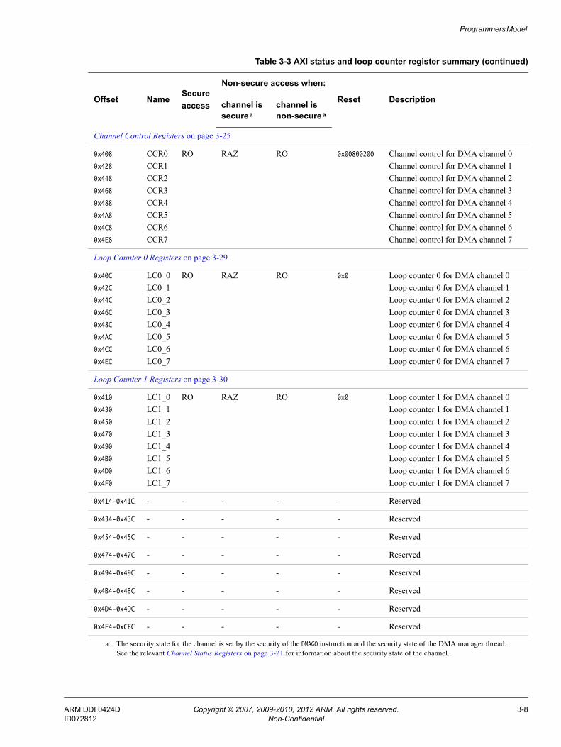
Programmers Model
Channel Control Registers on page 3-25
0x408
0x428
0x448
0x468
0x488
0x4A8
0x4C8
0x4E8
CCR0CCR1CCR2CCR3CCR4CCR5CCR6CCR7
RO RAZ RO 0x00800200 Channel control for DMA channel 0Channel control for DMA channel 1Channel control for DMA channel 2Channel control for DMA channel 3Channel control for DMA channel 4Channel control for DMA channel 5Channel control for DMA channel 6Channel control for DMA channel 7
Loop Counter 0 Registers on page 3-29
0x40C
0x42C
0x44C
0x46C
0x48C
0x4AC
0x4CC
0x4EC
LC0_0LC0_1LC0_2LC0_3LC0_4LC0_5LC0_6LC0_7
RO RAZ RO 0x0 Loop counter 0 for DMA channel 0Loop counter 0 for DMA channel 1Loop counter 0 for DMA channel 2Loop counter 0 for DMA channel 3Loop counter 0 for DMA channel 4Loop counter 0 for DMA channel 5Loop counter 0 for DMA channel 6Loop counter 0 for DMA channel 7
Loop Counter 1 Registers on page 3-30
0x410
0x430
0x450
0x470
0x490
0x4B0
0x4D0
0x4F0
LC1_0LC1_1LC1_2LC1_3LC1_4LC1_5LC1_6LC1_7
RO RAZ RO 0x0 Loop counter 1 for DMA channel 0Loop counter 1 for DMA channel 1Loop counter 1 for DMA channel 2Loop counter 1 for DMA channel 3Loop counter 1 for DMA channel 4Loop counter 1 for DMA channel 5Loop counter 1 for DMA channel 6Loop counter 1 for DMA channel 7
0x414-0x41C - - - - - Reserved
0x434-0x43C - - - - - Reserved
0x454-0x45C - - - - - Reserved
0x474-0x47C - - - - - Reserved
0x494-0x49C - - - - - Reserved
0x4B4-0x4BC - - - - - Reserved
0x4D4-0x4DC - - - - - Reserved
0x4F4-0xCFC - - - - - Reserved
a. The security state for the channel is set by the security of the DMAGO instruction and the security state of the DMA manager thread. See the relevant Channel Status Registers on page 3-21 for information about the security state of the channel.
Table 3-3 AXI status and loop counter register summary (continued)
Offset NameSecureaccess
Non-secure access when:
Reset Descriptionchannel is securea
channel is non-securea
ARM DDI 0424D Copyright © 2007, 2009-2010, 2012 ARM. All rights reserved. 3-8ID072812 Non-Confidential
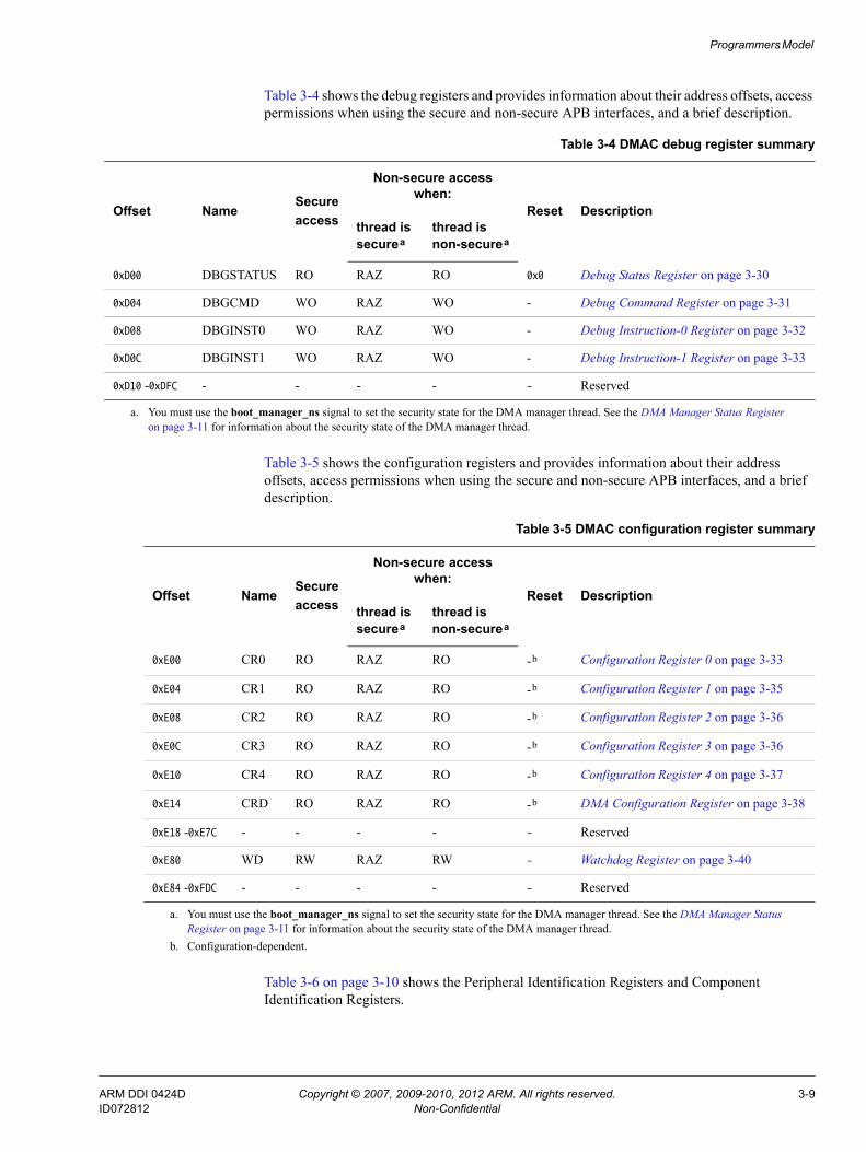
Programmers Model
Table 3-4 shows the debug registers and provides information about their address offsets, access permissions when using the secure and non-secure APB interfaces, and a brief description.
Table 3-5 shows the configuration registers and provides information about their address offsets, access permissions when using the secure and non-secure APB interfaces, and a brief description.
Table 3-6 on page 3-10 shows the Peripheral Identification Registers and Component Identification Registers.
Table 3-4 DMAC debug register summary
Offset NameSecureaccess
Non-secure access when:
Reset Descriptionthread is securea
thread is non-securea
0xD00 DBGSTATUS RO RAZ RO 0x0 Debug Status Register on page 3-30
0xD04 DBGCMD WO RAZ WO - Debug Command Register on page 3-31
0xD08 DBGINST0 WO RAZ WO - Debug Instruction-0 Register on page 3-32
0xD0C DBGINST1 WO RAZ WO - Debug Instruction-1 Register on page 3-33
0xD10 -0xDFC - - - - - Reserved
a. You must use the boot_manager_ns signal to set the security state for the DMA manager thread. See the DMA Manager Status Register on page 3-11 for information about the security state of the DMA manager thread.
Table 3-5 DMAC configuration register summary
Offset NameSecureaccess
Non-secure access when:
Reset Descriptionthread is securea
thread is non-securea
0xE00 CR0 RO RAZ RO -b Configuration Register 0 on page 3-33
0xE04 CR1 RO RAZ RO -b Configuration Register 1 on page 3-35
0xE08 CR2 RO RAZ RO -b Configuration Register 2 on page 3-36
0xE0C CR3 RO RAZ RO -b Configuration Register 3 on page 3-36
0xE10 CR4 RO RAZ RO -b Configuration Register 4 on page 3-37
0xE14 CRD RO RAZ RO -b DMA Configuration Register on page 3-38
0xE18 -0xE7C - - - - - Reserved
0xE80 WD RW RAZ RW - Watchdog Register on page 3-40
0xE84 -0xFDC - - - - - Reserved
a. You must use the boot_manager_ns signal to set the security state for the DMA manager thread. See the DMA Manager Status Register on page 3-11 for information about the security state of the DMA manager thread.
b. Configuration-dependent.
ARM DDI 0424D Copyright © 2007, 2009-2010, 2012 ARM. All rights reserved. 3-9ID072812 Non-Confidential

Programmers Model
Table 3-6 Peripheral and component identification register summary
Offset Name Type Reset Description
0xFE0-0xFEC periph_id_n RO Configuration-dependent Peripheral Identification Registers on page 3-41
0xFF0-0xFFC pcell_id_n RO Configuration-dependent Component Identification Registers 0-3 on page 3-43
ARM DDI 0424D Copyright © 2007, 2009-2010, 2012 ARM. All rights reserved. 3-10ID072812 Non-Confidential

Programmers Model
3.3 Register descriptionsThis section describes the DMAC registers. Register summary on page 3-5 provides a summary of each register.
3.3.1 DMA Manager Status Register
The DSR Register characteristics are:
Purpose Returns information about the status of the DMA manager thread.
Usage constraints No usage constraints.
Configurations Available in all configurations of the DMAC.
Attributes See the register summary in Table 3-1 on page 3-5.
Figure 3-2 shows the DSR Register bit assignments.
Figure 3-2 DSR Register bit assignments
Table 3-7 shows the DSR Register bit assignments.
31 10 9 8 4 3 0
Undefined
DNS
Wakeup event DMA status
Table 3-7 DSR Register bit assignments
Bits Name Description
[31:10] - Read UNDEFINED.
ARM DDI 0424D Copyright © 2007, 2009-2010, 2012 ARM. All rights reserved. 3-11ID072812 Non-Confidential

Programmers Model
3.3.2 DMA Program Counter Register
The DPC Register characteristics are:
Purpose Provides the value of the program counter for the DMA manager thread.
Usage constraints No usage constraints.
Configurations Available in all configurations of the DMAC.
Attributes See the register summary in Table 3-1 on page 3-5.
Figure 3-3 shows the DPC Register bit assignments.
Figure 3-3 DPC Register bit assignments
Table 3-8 shows the DPC Register bit assignments.
[9] DNS Provides the security status of the DMA manager thread:0 = DMA manager operates in the Secure state1 = DMA manager operates in the Non-secure state.
Note You must use the boot_manager_ns signal to set the secure state of the DMA manager thread.
[8:4] Wakeup_event When the DMA manager thread executes a DMAWFE instruction, it waits for the following event to occur:0b00000 = event[0]0b00001 = event[1]0b00010 = event[2]...0b11111 = event[31].
[3:0] DMA status The operating state of the DMA manager:0b0000 = Stopped0b0001 = Executing0b0010 = Cache miss0b0011 = Updating PC0b0100 = Waiting for event0b0101-0b1110 = reserved0b1111 = Faulting.See Operating states on page 2-8 for more information.
Table 3-7 DSR Register bit assignments (continued)
Bits Name Description
31 0
pc_mgr
Table 3-8 DPC Register bit assignments
Bits Name Description
[31:0] pc_mgr Program counter for the DMA manager thread
ARM DDI 0424D Copyright © 2007, 2009-2010, 2012 ARM. All rights reserved. 3-12ID072812 Non-Confidential

Programmers Model
3.3.3 Interrupt Enable Register
The INTEN Register characteristics are:
Purpose When the DMAC executes a DMASEV instruction, each bit of the INTEN Register controls if the DMAC signals:• The specified event to all of the threads.• An interrupt using the corresponding irq.
Usage constraints No usage constraints.
Configurations Available in all configurations of the DMAC.
Attributes See the register summary in Table 3-1 on page 3-5.
Figure 3-4 shows the INTEN Register bit assignments.
Figure 3-4 INTEN Register bit assignments
Table 3-9 shows the INTEN Register bit assignments.
3.3.4 Event-Interrupt Raw Status Register
The INT_EVENT_RIS Register characteristics are:
Purpose Returns the status of the event-interrupt resources.
Usage constraints No usage constraints.
Configurations Available in all configurations of the DMAC.
31 30 29 28 27 26 25 24 23 22 21 20 19 18 17 16 15 14 13 12 11 10 9 8 7 6 5 4 3 2 1 0
.
.
.
event_irq_select for event 0
event_irq_select for event 31
event_irq_select for event 1event_irq_select for event 2
Table 3-9 INTEN Register bit assignments
Bits Name Description
[31:0] event_irq_select Program the appropriate bit to control how the DMAC responds when it executes DMASEV:Bit [N] = 0 If the DMAC executes DMASEV for the event-interrupt resource N then the DMAC signals
event N to all of the threads. Set bit [N] to 0 if your system design does not use irq[N] to signal an interrupt request.
Bit [N] = 1 If the DMAC executes DMASEV for the event-interrupt resource N then the DMAC sets irq[N] HIGH. Set bit [N] to 1 if your system design requires irq[N] to signal an interrupt request.
Note See DMASEV on page 4-14 for information about selecting an event number.
ARM DDI 0424D Copyright © 2007, 2009-2010, 2012 ARM. All rights reserved. 3-13ID072812 Non-Confidential
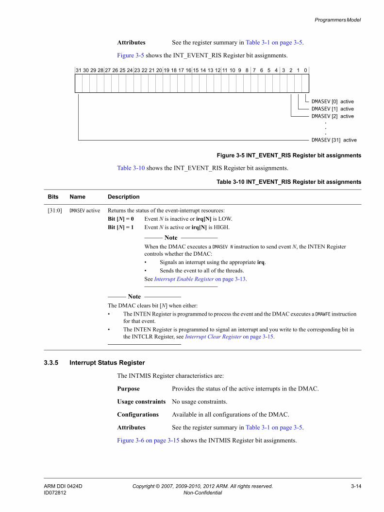
Programmers Model
Attributes See the register summary in Table 3-1 on page 3-5.
Figure 3-5 shows the INT_EVENT_RIS Register bit assignments.
Figure 3-5 INT_EVENT_RIS Register bit assignments
Table 3-10 shows the INT_EVENT_RIS Register bit assignments.
3.3.5 Interrupt Status Register
The INTMIS Register characteristics are:
Purpose Provides the status of the active interrupts in the DMAC.
Usage constraints No usage constraints.
Configurations Available in all configurations of the DMAC.
Attributes See the register summary in Table 3-1 on page 3-5.
Figure 3-6 on page 3-15 shows the INTMIS Register bit assignments.
31 30 29 28 27 26 25 24 23 22 21 20 19 18 17 16 15 14 13 12 11 10 9 8 7 6 5 4 3 2 1 0
.
.
.
DMASEV [0] active
DMASEV [31] active
DMASEV [1] activeDMASEV [2] active
Table 3-10 INT_EVENT_RIS Register bit assignments
Bits Name Description
[31:0] DMASEV active Returns the status of the event-interrupt resources:Bit [N] = 0 Event N is inactive or irq[N] is LOW.Bit [N] = 1 Event N is active or irq[N] is HIGH.
Note When the DMAC executes a DMASEV N instruction to send event N, the INTEN Register
controls whether the DMAC:• Signals an interrupt using the appropriate irq.• Sends the event to all of the threads.See Interrupt Enable Register on page 3-13.
Note The DMAC clears bit [N] when either:• The INTEN Register is programmed to process the event and the DMAC executes a DMAWFE instruction
for that event.• The INTEN Register is programmed to signal an interrupt and you write to the corresponding bit in
the INTCLR Register, see Interrupt Clear Register on page 3-15.
ARM DDI 0424D Copyright © 2007, 2009-2010, 2012 ARM. All rights reserved. 3-14ID072812 Non-Confidential

Programmers Model
Figure 3-6 INTMIS Register bit assignments
Table 3-11 shows the INTMIS Register bit assignments.
3.3.6 Interrupt Clear Register
The INTCLR Register characteristics are:
Purpose Provides the status of the active interrupts in the DMAC.
Usage constraints No usage constraints.
Configurations Available in all configurations of the DMAC.
Attributes See the register summary in Table 3-1 on page 3-5.
Figure 3-7 shows the INTCLR Register bit assignments.
Figure 3-7 INTCLR Register bit assignments
31 30 29 28 27 26 25 24 23 22 21 20 19 18 17 16 15 14 13 12 11 10 9 8 7 6 5 4 3 2 1 0
.
.
.
irq_status for irq[0]
irq_status for irq[31]
irq_status for irq[1]
irq_status for irq[2]
Table 3-11 INTMIS Register bit assignments
Bits Name Description
[31:0] irq_status Provides the status of the interrupts that are active in the DMAC:Bit [N] = 0 Interrupt N is inactive and therefore irq[N] is LOW.Bit [N] = 1 Interrupt N is active and therefore irq[N] is HIGH.
Note You must use the INTCLR Register to set bit [N] to 0, see Interrupt Clear Register.
Note Bit [N] is 0 if the INTEN Register programs DMASEV to signal an event, see Interrupt Enable Register on page 3-13.
31 30 29 28 27 26 25 24 23 22 21 20 19 18 17 16 15 14 13 12 11 10 9 8 7 6 5 4 3 2 1 0
.
.
.
irq_clr for irq[0]
irq_clr for irq[31]
irq_clr for irq[1]
irq_clr for irq[2]
ARM DDI 0424D Copyright © 2007, 2009-2010, 2012 ARM. All rights reserved. 3-15ID072812 Non-Confidential

Programmers Model
Table 3-12 shows the INTCLR Register bit assignments.
3.3.7 Fault Status DMA Manager Register
The FSRD Register characteristics are:
Purpose Provides the fault status of the DMA manager.
Usage constraints No usage constraints.
Configurations Available in all configurations of the DMAC.
Attributes See the register summary in Table 3-1 on page 3-5.
Figure 3-8 shows the FSRD Register bit assignments.
Figure 3-8 FSRD Register bit assignments
Table 3-13 shows the FSRD Register bit assignments.
3.3.8 Fault Status DMA Channel Register
The FSRC Register characteristics are:
Purpose Provides the fault status for the DMA channels.
Usage constraints No usage constraints.
Configurations Available in all configurations of the DMAC.
Attributes See the register summary in Table 3-1 on page 3-5.
Figure 3-9 on page 3-17 shows the FSRC Register bit assignments.
Table 3-12 INTCLR Register bit assignments
Bits Name Description
[31:0] irq_clr Controls the clearing of the irq outputs:Bit [N] = 0 The status of irq[N] does not change.Bit [N] = 1 The DMAC sets irq[N] LOW if the INTEN Register programs the DMAC to signal an interrupt.
Otherwise, the status of irq[N] does not change. See Interrupt Enable Register on page 3-13.
31 1 0
fs_mgr
Reserved
Table 3-13 FSRD Register bit assignments
Bits Name Description
[31:1] - Reserved, read UNDEFINED.
{0] fs_mgr Provides the fault status of the DMA manager. Read as:0 = the DMA manager thread is not in the Faulting state1 = the DMA manager thread is in the Faulting state. See Fault Type DMA Manager Register on page 3-17 for information about the type of fault that occurred.
ARM DDI 0424D Copyright © 2007, 2009-2010, 2012 ARM. All rights reserved. 3-16ID072812 Non-Confidential

Programmers Model
Figure 3-9 FSRC Register bit assignments
Table 3-14 shows the FSRC Register bit assignments.
3.3.9 Fault Type DMA Manager Register
The FTRD Register characteristics are:
Purpose Provides the type of fault that occurred to move the DMA manager to the Faulting state.
Usage constraints No usage constraints.
Configurations Available in all configurations of the DMAC.
Attributes See the register summary in Table 3-1 on page 3-5.
Figure 3-10 shows the FTRD Register bit assignments.
Figure 3-10 FTRD Register bit assignments
31 8 7 6 5 4 3 2 1 0
.
.
.
fault_status for DMA channel 0fault_status for DMA channel 1fault_status for DMA channel 2
fault_status for DMA channel 7
Reserved
Table 3-14 FSRC Register bit assignments
Bits Name Description
[31:8] - Reserved, read UNDEFINED.
[7:0] fault_status Each bit provides the fault status of the corresponding channel. Read as:Bit [N] = 0 No fault is present on DMA channel N.Bit [N] = 1 DMA channel N is in the Faulting or Faulting completing state. See Fault Type DMA Channel
Registers on page 3-18 for information about the type of fault that occurred.
31 6 5 4 3 2 1 0
Reserved
1617
dmago_errReserved
operand_invalidundef_instr
mgr_evnt_err
Reserved
instr_fetch_err
1530 29
dbg_instrReserved
ARM DDI 0424D Copyright © 2007, 2009-2010, 2012 ARM. All rights reserved. 3-17ID072812 Non-Confidential

Programmers Model
Table 3-15 shows the FTRD Register bit assignments.
3.3.10 Fault Type DMA Channel Registers
The FTRn Register characteristics are:
Purpose Provides the type of fault that occurred to move a DMA channel to the Faulting state.
Usage constraints No usage constraints.
Configurations Available in all configurations of the DMAC. The DMAC provides a FTRn Register for each DMA channel that it contains.
Attributes See the register summary in Table 3-1 on page 3-5.
Table 3-15 FTRD Register bit assignments
Bits Name Description
[31] - Read UNDEFINED.
[30] dbg_instr If the DMA manager aborts, this bit indicates whether the erroneous instruction was read from the system memory or from the debug interface:0 = instruction that generated an abort was read from system memory1 = instruction that generated an abort was read from the debug interface.
[29:17] - Read UNDEFINED.
[16] instr_fetch_err Indicates the AXI response that the DMAC receives on the RRESP bus, after the DMA manager performs an instruction fetch:0 = OKAY response1 = EXOKAY, SLVERR, or DECERR response.
[15:6] - Read UNDEFINED.
[5] mgr_evnt_err Indicates whether the DMA manager was attempting to execute DMAWFE or DMASEV with inappropriate security permissions:0 = the DMA manager has appropriate security to execute DMAWFE or DMASEV1 = a DMA manager thread in the Non-secure state attempted to execute either:• DMAWFE to wait for a secure event.• DMASEV to create a secure event or secure interrupt.
[4] dmago_err Indicates whether the DMA manager was attempting to execute DMAGO with inappropriate security permissions:0 = the DMA manager has appropriate security to execute DMAGO1 = a DMA manager thread in the Non-secure state attempted to execute DMAGO to create a DMA channel operating in the Secure state.
[3:2] - Read UNDEFINED.
[1] operand_invalid Indicates whether the DMA manager was attempting to execute an instruction operand that was not valid for the configuration of the DMAC:0 = valid operand1 = invalid operand.
[0] undef_instr Indicates whether the DMA manager was attempting to execute an undefined instruction:0 = defined instruction1 = undefined instruction.
ARM DDI 0424D Copyright © 2007, 2009-2010, 2012 ARM. All rights reserved. 3-18ID072812 Non-Confidential

Programmers Model
Depending on the fault type, the DMAC abort is categorized as:
Precise abort With the thread in the faulting state, you can read the CPCn Register to determine the value of the program counter that caused the fault to occur. See Channel Program Counter Registers on page 3-23.
Imprecise abort The program counter register, CPCn Register, does not contain the address of the instruction that caused the fault to occur. See Channel Program Counter Registers on page 3-23.
Figure 3-11 shows the FTRn Register bit assignments.
Figure 3-11 FTRn Register bit assignments
Table 3-16 shows the FTRn Register bit assignments.
31 8 7 6 5 4 2 1 01819 17 16 15 1213 11
data_read_errdata_write_errinstr_fetch_err
Reserved
mfifo_errch_rdwr_errch_periph_errch_evnt_err
Reservedoperand_invalidundef_instr
0
0x040Address offset
Channel <n> 1
0x044
2
0x048
3
0x04C
4
0x050
5
0x054
6
0x058
7
0x05C
FTR<n> Register address mapping:
30 29
dbg_instrlockup_err
14
st_data_unavailable
ReservedReserved
Table 3-16 FTRn Register bit assignments
Bits Name Description
[31] lockup_err Indicates whether the DMA channel has locked-up because of resource starvation:0 = DMA channel has adequate resources1 = DMA channel has locked-up because of insufficient resources.This fault is an imprecise abort.
[30] dbg_instr If the DMA channel aborts, this bit indicates whether the erroneous instruction was read from the system memory or from the debug interface:0 = instruction that generated an abort was read from system memory1 = instruction that generated an abort was read from the debug interface.This fault is an imprecise abort but the bit is only valid when a precise abort occurs.
[29:19] - Reserved, read UNDEFINED.
[18] data_read_err Indicates the AXI response that the DMAC receives on the RRESP bus, after the DMA channel thread performs a data read:0 = OKAY response1 = EXOKAY, SLVERR, or DECERR response.This fault is an imprecise abort.
[17] data_write_err Indicates the AXI response that the DMAC receives on the BRESP bus, after the DMA channel thread performs a data write:0 = OKAY response1 = EXOKAY, SLVERR, or DECERR response.This fault is an imprecise abort.
ARM DDI 0424D Copyright © 2007, 2009-2010, 2012 ARM. All rights reserved. 3-19ID072812 Non-Confidential
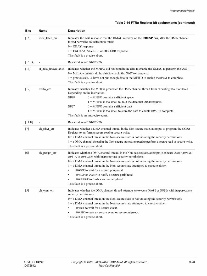
Programmers Model
[16] instr_fetch_err Indicates the AXI response that the DMAC receives on the RRESP bus, after the DMA channel thread performs an instruction fetch:0 = OKAY response1 = EXOKAY, SLVERR, or DECERR response.This fault is a precise abort.
[15:14] - Reserved, read UNDEFINED.
[13] st_data_unavailable Indicates whether the MFIFO did not contain the data to enable the DMAC to perform the DMAST:0 = MFIFO contains all the data to enable the DMAST to complete1 = previous DMALDs have not put enough data in the MFIFO to enable the DMAST to complete.This fault is a precise abort.
[12] mfifo_err Indicates whether the MFIFO prevented the DMA channel thread from executing DMALD or DMAST. Depending on the instruction:DMALD 0 = MFIFO contains sufficient space
1 = MFIFO is too small to hold the data that DMALD requires.DMAST 0 = MFIFO contains sufficient data
1 = MFIFO is too small to store the data to enable DMAST to complete.This fault is an imprecise abort.
[11:8] - Reserved, read UNDEFINED.
[7] ch_rdwr_err Indicates whether a DMA channel thread, in the Non-secure state, attempts to program the CCRn Register to perform a secure read or secure write:0 = a DMA channel thread in the Non-secure state is not violating the security permissions1 = a DMA channel thread in the Non-secure state attempted to perform a secure read or secure write.This fault is a precise abort.
[6] ch_periph_err Indicates whether a DMA channel thread, in the Non-secure state, attempts to execute DMAWFP, DMALDP, DMASTP, or DMAFLUSHP with inappropriate security permissions:0 = a DMA channel thread in the Non-secure state is not violating the security permissions1 = a DMA channel thread in the Non-secure state attempted to execute either:• DMAWFP to wait for a secure peripheral.• DMALDP or DMASTP to notify a secure peripheral.• DMAFLUSHP to flush a secure peripheral.This fault is a precise abort.
[5] ch_evnt_err Indicates whether the DMA channel thread attempts to execute DMAWFE or DMASEV with inappropriate security permissions:0 = a DMA channel thread in the Non-secure state is not violating the security permissions1 = a DMA channel thread in the Non-secure state attempted to execute either:• DMAWFE to wait for a secure event.• DMASEV to create a secure event or secure interrupt.This fault is a precise abort.
Table 3-16 FTRn Register bit assignments (continued)
Bits Name Description
ARM DDI 0424D Copyright © 2007, 2009-2010, 2012 ARM. All rights reserved. 3-20ID072812 Non-Confidential

Programmers Model
3.3.11 Channel Status Registers
The CSRn Register characteristics are:
Purpose Provides the status of the DMA program on a DMA channel.
Usage constraints No usage constraints.
Configurations Available in all configurations of the DMAC. The DMAC provides a CSRn Register for each DMA channel that it contains.
Attributes See the register summary in Table 3-2 on page 3-6.
Figure 3-12 shows the CSRn Register bit assignments.
Figure 3-12 CSRn Register bit assignments
[4:2] - Reserved, read UNDEFINED.
[1] operand_invalid Indicates whether the DMA channel thread was attempting to execute an instruction operand that was not valid for the configuration of the DMAC:0 = valid operand1 = invalid operand.This fault is a precise abort.
[0] undef_instr Indicates whether the DMA channel thread was attempting to execute an undefined instruction:0 = defined instruction1 = undefined instruction.This fault is a precise abort.
Table 3-16 FTRn Register bit assignments (continued)
Bits Name Description
31 22 21 20 16 15 14 13 9 8 4 3 0
CNS
Reserved
dmawfp_periphdmawfp_b_ns
Undefined Channel status
Wakeup number
0
0x100Address offset
Channel <n> 1
0x108
2
0x110
3
0x118
4
0x120
5
0x128
6
0x130
7
0x138
CSR<n> Register address mapping:
CSR<n> Register bit assignment:
Reserved
ARM DDI 0424D Copyright © 2007, 2009-2010, 2012 ARM. All rights reserved. 3-21ID072812 Non-Confidential

Programmers Model
Table 3-17 shows the CSRn Register bit assignments.
Table 3-17 CSRn Register bit assignments
Bits Name Description
[31:22] - Reserved, read UNDEFINED.
[21] CNS The channel non-secure bit provides the security of the DMA channel:0 = DMA channel operates in the Secure state1 = DMA channel operates in the Non-secure state.
Note The DMAGO instruction determines the security state of a DMA channel. See DMAGO on page 4-6.
[20:16] - Reserved, read UNDEFINED.
[15] dmawfp_periph When the DMA channel thread executes DMAWFP, this bit indicates whether the periph operand was set:0 = DMAWFP executed with the periph operand not set1 = DMAWFP executed with the periph operand set.See DMAWFP on page 4-18.
[14] dmawfp_b_ns When the DMA channel thread executes DMAWFP, this bit indicates whether the burst or single operand were set:0 = DMAWFP executed with the single operand set1 = DMAWFP executed with the burst operand set.See DMAWFP on page 4-18.
[13:9] - Reserved, read UNDEFINED.
[8:4] Wakeup number If the DMA channel is in the Waiting for event state, or the Waiting for peripheral state, then these bits indicate the event or peripheral number that the channel is waiting for:0b00000 = DMA channel is waiting for event, or peripheral, 00b00001 = DMA channel is waiting for event, or peripheral, 10b00010 = DMA channel is waiting for event, or peripheral, 2...0b11111 = DMA channel is waiting for event, or peripheral, 31.
[3:0] Channel status The channel status encoding is:0b0000 = Stopped0b0001 = Executing0b0010 = Cache miss0b0011 = Updating PC0b0100 = Waiting for event0b0101 = At barrier0b0110 = reserved0b0111 = Waiting for peripheral0b1000 = Killing0b1001 = Completing0b1010-0b1101 = reserved0b1110 = Faulting completing0b1111 = Faulting.See Operating states on page 2-8 for more information.
ARM DDI 0424D Copyright © 2007, 2009-2010, 2012 ARM. All rights reserved. 3-22ID072812 Non-Confidential

Programmers Model
3.3.12 Channel Program Counter Registers
The CPCn Register characteristics are:
Purpose Provides the value of the program counter for the DMA channel thread.
Usage constraints No usage constraints.
Configurations Available in all configurations of the DMAC. The DMAC provides a CPCn Register for each DMA channel that it contains.
Attributes See the register summary in Table 3-2 on page 3-6.
Figure 3-13 shows the CPCn Register bit assignments.
Figure 3-13 CPC Register bit assignments and address offsets
Table 3-18 shows the CPCn Register bit assignments.
3.3.13 Source Address Registers
The SARn Register characteristics are:
Purpose Provides the address of the source data for a DMA channel.The DMAC writes the initial source address value to the SA Register when the DMA channel thread executes a DMAMOV SAR instruction. If a DMAMOV CCR instruction programs the source address to increment, each time the DMA channel executes DMALD, it updates the value to indicate the address that the next DMALD must use. See DMAMOV on page 4-13 for more information.
Usage constraints No usage constraints.
Configurations Available in all configurations of the DMAC. The DMAC provides a SARn Register for each DMA channel that it contains.
Attributes See the register summary in Table 3-3 on page 3-7.
Figure 3-14 on page 3-24 shows the SARn Register bit assignments.
31 0
pc_chnl
0
0x104Address offset
Channel n 1
0x10C
2
0x114
3
0x11C
4
0x124
5
0x12C
6
0x134
7
0x13C
CPCn Register address mapping:
CPCn Register bit assignment:
Table 3-18 CPCn Register bit assignments
Bits Name Description
[31:0] pc_chnl Program counter for the DMA channel n thread, where n depends on the address of the register. See Figure 3-13.
ARM DDI 0424D Copyright © 2007, 2009-2010, 2012 ARM. All rights reserved. 3-23ID072812 Non-Confidential

Programmers Model
Figure 3-14 SARn Register bit assignments and address offsets
Table 3-19 shows the SARn Register bit assignments.
3.3.14 Destination Address Registers
The DARn Register characteristics are:
Purpose Provides the address for the destination data for a DMA channel.The DMAC writes the initial destination address value to the DA Register when the DMA channel thread executes a DMAMOV DAR instruction. If a subsequent DMAMOV CCR instruction programs the destination address to increment, then each time the DMA channel executes DMAST, it updates the value to indicate the address that the next DMAST must use. See DMAMOV on page 4-13 for more information.
Usage constraints No usage constraints.
Configurations Available in all configurations of the DMAC. The DMAC provides a DARn Register for each DMA channel that it contains.
Attributes See the register summary in Table 3-3 on page 3-7.
Figure 3-15 shows the DARn Register bit assignments.
Figure 3-15 DARn Register bit assignments and address offsets
31 0
src_addr
0
0x400
1
0x420
2
0x440
3
0x460
4
0x480
5
0x4A0
6
0x4C0
7
0x4E0
Register address mapping:
SARn Register bit assignments:
Address offset
Channel n
Register name SAR0 SAR1 SAR2 SAR3 SAR4 SAR5 SAR6 SAR7
Table 3-19 SARn Register bit assignments
Bits Name Description
[31:0] src_addr Address of the source data for DMA channel n, where n depends on the address of the register. See Figure 3-14.
31 0
dst_addr
0
0x404Address offset
Channel n 1
0x424
2
0x444
3
0x464
4
0x484
5
0x4A4
6
0x4C4
7
0x4E4
Register address mapping:
DARn Register bit assignments:
Register name DAR0 DAR1 DAR2 DAR3 DAR4 DAR5 DAR6 DAR7
ARM DDI 0424D Copyright © 2007, 2009-2010, 2012 ARM. All rights reserved. 3-24ID072812 Non-Confidential

Programmers Model
Table 3-20 shows the DARn Register bit assignments.
3.3.15 Channel Control Registers
The CCRn Register characteristics are:
Purpose Controls the AXI transactions that the DMAC uses for a DMA channel.The DMAC writes to the corresponding CC Register when a DMA channel thread executes a DMAMOV CCR instruction.
Usage constraints No usage constraints.
Configurations Available in all configurations of the DMAC. The DMAC provides a CCRn Register for each DMA channel that it contains.
Attributes See the register summary in Table 3-3 on page 3-7.
Figure 3-16 shows the CCRn Register bit assignments.
Figure 3-16 CCRn Register bit assignments and base address offsets
Table 3-20 DARn Register bit assignments
Bits Name Description
[31:0] dst_addr Address for the destination data for DMA channel n, where n depends on the address of the register. See Figure 3-15 on page 3-24.
31 28 27 25 24 22 21 18 17 15 14 13 11 10 8 7 4 3 1 0
endian_swap_size
dst_cache_ctrl
dst_prot_ctrl src_cache_ctrl
dst_incdst_burst_size
src_burst_size
dst_burst_len
src_inc
src_burst_len
src_prot_ctrl
Source controlDestination controlCCRn Register bit assignments:
0
0x408Address offset
Channel n 1
0x428
2
0x448
3
0x468
4
0x488
5
0x4A8
6
0x4C8
7
0x4E8
Register address mapping:
Register name CCR0 CCR1 CCR2 CCR3 CCR4 CCR5 CCR6 CCR7
30
reserved
ARM DDI 0424D Copyright © 2007, 2009-2010, 2012 ARM. All rights reserved. 3-25ID072812 Non-Confidential

Programmers Model
Table 3-21 shows the CCRn Register bit assignments.
Table 3-21 CCRn Register bit assignments
Bits Name Description
[31] - Reserved, read UNDEFINED.
[30:28] endian_swap_size See Endian swap size on page 3-28.
[27:25] dst_cache_ctrl Programs the state of AWCACHE[3,1:0]a when the DMAC writes the destination data.Bit [27] 0 = AWCACHE[3] is LOW
1 = AWCACHE[3] is HIGH.Bit [26] 0 = AWCACHE[1] is LOW
1 = AWCACHE[1] is HIGH.Bit [25] 0 = AWCACHE[0] is LOW
1 = AWCACHE[0] is HIGH.
Note AWCACHE[2] is tied LOW by the DMAC.Setting AWCACHE[3,1]=0b10 violates the AXI protocol. See the AMBA AXI and ACE Protocol Specification.
[24:22] dst_prot_ctrl Programs the state of AWPROT[2:0]a when the DMAC writes the destination data.Bit [24] 0 = AWPROT[2] is LOW
1 = AWPROT[2] is HIGH.Bit [23] 0 = AWPROT[1] is LOW
1 = AWPROT[1] is HIGH.Bit [22] 0 = AWPROT[0] is LOW
1 = AWPROT[0] is HIGH.
Note Only DMA channels in the Secure state can program AWPROT[1] LOW, that is, a secure access. If a DMA channel in the Non-secure state attempts to set AWPROT[1] LOW, then the DMA channel aborts.
[21:18] dst_burst_len For each burst, these bits program the number of data transfers that the DMAC performs when it writes the destination data:0b0000 = 1 data transfer0b0001 = 2 data transfers0b0010 = 3 data transfers...0b1111 = 16 data transfers.The total number of bytes that the DMAC writes out of the MFIFO when it executes a DMAST instruction is the product of dst_burst_len and dst_burst_size.
Note These bits control the state of AWLEN[3:0].
ARM DDI 0424D Copyright © 2007, 2009-2010, 2012 ARM. All rights reserved. 3-26ID072812 Non-Confidential
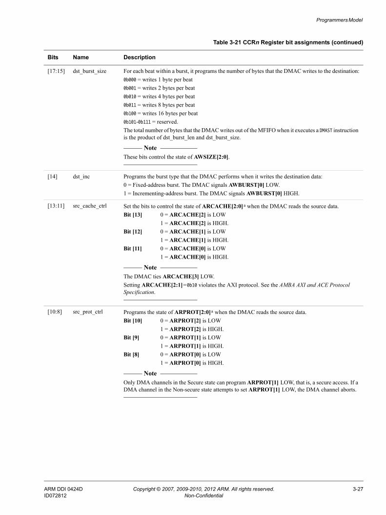
Programmers Model
[17:15] dst_burst_size For each beat within a burst, it programs the number of bytes that the DMAC writes to the destination:0b000 = writes 1 byte per beat0b001 = writes 2 bytes per beat0b010 = writes 4 bytes per beat0b011 = writes 8 bytes per beat0b100 = writes 16 bytes per beat0b101-0b111 = reserved.The total number of bytes that the DMAC writes out of the MFIFO when it executes a DMAST instruction is the product of dst_burst_len and dst_burst_size.
Note These bits control the state of AWSIZE[2:0].
[14] dst_inc Programs the burst type that the DMAC performs when it writes the destination data:0 = Fixed-address burst. The DMAC signals AWBURST[0] LOW.1 = Incrementing-address burst. The DMAC signals AWBURST[0] HIGH.
[13:11] src_cache_ctrl Set the bits to control the state of ARCACHE[2:0]a when the DMAC reads the source data.Bit [13] 0 = ARCACHE[2] is LOW
1 = ARCACHE[2] is HIGH.Bit [12] 0 = ARCACHE[1] is LOW
1 = ARCACHE[1] is HIGH.Bit [11] 0 = ARCACHE[0] is LOW
1 = ARCACHE[0] is HIGH.
Note The DMAC ties ARCACHE[3] LOW.Setting ARCACHE[2:1]=0b10 violates the AXI protocol. See the AMBA AXI and ACE Protocol Specification.
[10:8] src_prot_ctrl Programs the state of ARPROT[2:0]a when the DMAC reads the source data.Bit [10] 0 = ARPROT[2] is LOW
1 = ARPROT[2] is HIGH.Bit [9] 0 = ARPROT[1] is LOW
1 = ARPROT[1] is HIGH.Bit [8] 0 = ARPROT[0] is LOW
1 = ARPROT[0] is HIGH.
Note Only DMA channels in the Secure state can program ARPROT[1] LOW, that is, a secure access. If a DMA channel in the Non-secure state attempts to set ARPROT[1] LOW, the DMA channel aborts.
Table 3-21 CCRn Register bit assignments (continued)
Bits Name Description
ARM DDI 0424D Copyright © 2007, 2009-2010, 2012 ARM. All rights reserved. 3-27ID072812 Non-Confidential

Programmers Model
Note The DMAC does not generate:• Locked or exclusive accesses.• WRAP transfers. Therefore, ARBURST[1] and AWBURST[1] are always LOW.
Endian swap size
Table 3-22 on page 3-29 defines whether data can be swapped between little-endian (LE) and byte-invariant big-endian (BE-8) formats, and if so, also defines the natural width of the data independently of the source and destination transaction sizes.
[7:4] src_burst_len For each burst, these bits program the number of data transfers that the DMAC performs when it reads the source data:0b0000 = 1 data transfer0b0001 = 2 data transfers0b0010 = 3 data transfers...0b1111 = 16 data transfers.The total number of bytes that the DMAC reads into the MFIFO when it executes a DMALD instruction is the product of src_burst_len and src_burst_size.
Note These bits control the state of ARLEN[3:0].
[3:1] src_burst_size For each beat within a burst, it programs the number of bytes that the DMAC reads from the source:0b000 = reads 1 byte per beat0b001 = reads 2 bytes per beat0b010 = reads 4 bytes per beat0b011 = reads 8 bytes per beat0b100 = reads 16 bytes per beat0b101-0b111 = reserved.The total number of bytes that the DMAC reads into the MFIFO when it executes a DMALD instruction is the product of src_burst_len and src_burst_size.
Note These bits control the state of ARSIZE[2:0].
[0] src_inc Programs the burst type that the DMAC performs when it reads the source data:0 = Fixed-address burst. The DMAC signals ARBURST[0] LOW.1 = Incrementing-address burst. The DMAC signals ARBURST[0] HIGH.
a. See the AMBA AXI and ACE Protocol Specification for information about this AXI signal.
Table 3-21 CCRn Register bit assignments (continued)
Bits Name Description
ARM DDI 0424D Copyright © 2007, 2009-2010, 2012 ARM. All rights reserved. 3-28ID072812 Non-Confidential

Programmers Model
This enables unaligned data streams to use the full bus-width, and to be correctly transformed, irrespective of the source and destination address alignments. The format is identical to AxSIZE, except that 0b000 indicates that no swap must occur.
Note See Endian swap size restrictions on page 2-35 for information about some restrictions that apply when you use this feature.
3.3.16 Loop Counter 0 Registers
The LC0_n Register characteristics are:
Purpose Provides the status of loop counter zero for the DMA channel. The DMAC updates this register when it executes DMALPEND[S|B], and the DMA channel thread is programmed to use loop counter zero. See DMALPEND[S|B] on page 4-11.
Usage constraints No usage constraints.
Configurations Available in all configurations of the DMAC. The DMAC provides a LC0_n Register for each DMA channel that it contains.
Attributes See the register summary in Table 3-3 on page 3-7.
Figure 3-17 shows the LC0_n Register bit assignments.
Figure 3-17 LC0_n Register bit assignments and base address offsets
Table 3-22 Swap data
Endian swap size Description
0b000 No swap, 8-bit data
0b001 Swap bytes within 16-bit data
0b010 Swap bytes within 32-bit data
0b011 Swap bytes within 64-bit data
0b100 Swap bytes within 128-bit data
0b101 Reserved
0b110 Reserved
0b111 Reserved
31 8 7 0
loop counter iterationsUndefined
0
0x40CAddress offset
Channel n 1
0x42C
2
0x44C
3
0x46C
4
0x4CC
5
0x4AC
6
0x4CC
7
0x4EC
Register address mapping:
Register name LC0_0 LC0_1 LC0_2 LC0_3 LC0_4 LC0_5 LC0_6 LC0_7
ARM DDI 0424D Copyright © 2007, 2009-2010, 2012 ARM. All rights reserved. 3-29ID072812 Non-Confidential
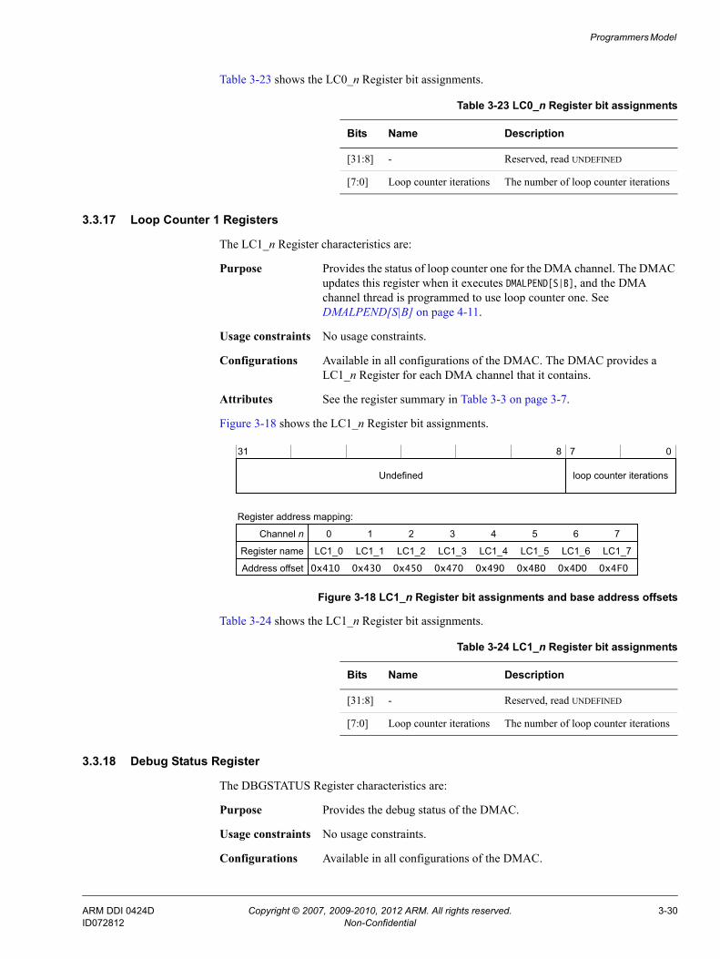
Programmers Model
Table 3-23 shows the LC0_n Register bit assignments.
3.3.17 Loop Counter 1 Registers
The LC1_n Register characteristics are:
Purpose Provides the status of loop counter one for the DMA channel. The DMAC updates this register when it executes DMALPEND[S|B], and the DMA channel thread is programmed to use loop counter one. See DMALPEND[S|B] on page 4-11.
Usage constraints No usage constraints.
Configurations Available in all configurations of the DMAC. The DMAC provides a LC1_n Register for each DMA channel that it contains.
Attributes See the register summary in Table 3-3 on page 3-7.
Figure 3-18 shows the LC1_n Register bit assignments.
Figure 3-18 LC1_n Register bit assignments and base address offsets
Table 3-24 shows the LC1_n Register bit assignments.
3.3.18 Debug Status Register
The DBGSTATUS Register characteristics are:
Purpose Provides the debug status of the DMAC.
Usage constraints No usage constraints.
Configurations Available in all configurations of the DMAC.
Table 3-23 LC0_n Register bit assignments
Bits Name Description
[31:8] - Reserved, read UNDEFINED
[7:0] Loop counter iterations The number of loop counter iterations
31 8 7 0
loop counter iterationsUndefined
0
0x410Address offset
Channel n 1
0x430
2
0x450
3
0x470
4
0x490
5
0x4B0
6
0x4D0
7
0x4F0
Register address mapping:
Register name LC1_0 LC1_1 LC1_2 LC1_3 LC1_4 LC1_5 LC1_6 LC1_7
Table 3-24 LC1_n Register bit assignments
Bits Name Description
[31:8] - Reserved, read UNDEFINED
[7:0] Loop counter iterations The number of loop counter iterations
ARM DDI 0424D Copyright © 2007, 2009-2010, 2012 ARM. All rights reserved. 3-30ID072812 Non-Confidential

Programmers Model
Attributes See the register summary in Table 3-4 on page 3-9.
Figure 3-19 shows the DBGSTATUS Register bit assignments.
Figure 3-19 DBGSTATUS Register bit assignments
Table 3-25 shows the DBGSTATUS Register bit assignments.
3.3.19 Debug Command Register
The DBGCMD Register characteristics are:
Purpose Controls the execution of debug commands in the DMAC as Issuing instructions to the DMAC using an APB interface on page 2-13 describes.
Usage constraints No usage constraints.
Configurations Available in all configurations of the DMAC.
Attributes See the register summary in Table 3-4 on page 3-9.
Figure 3-20 shows the DBGCMD Register bit assignments.
Figure 3-20 DBGCMD Register bit assignments
Table 3-26 shows the DBGCMD Register bit assignments.
31 1 0
Undefined
dbgstatus
Table 3-25 DBGSTATUS Register bit assignments
Bits Name Description
[31:1] - Reserved, read UNDEFINED.
[0] dbgstatus The debug status encoding is:0 = Idle1 = Busy.
31 1 0
Undefined
dbgcmd
2
Table 3-26 DBGCMD Register bit assignments
Bits Name Description
[31:2] - Reserved. Write as zero.
[1:0] dbgcmd The debug encoding is as follows:0b00 = execute the instruction that the DBGINST [1:0] Registers contain0b01 = reserved0b10 = reserved0b11 = reserved.
ARM DDI 0424D Copyright © 2007, 2009-2010, 2012 ARM. All rights reserved. 3-31ID072812 Non-Confidential
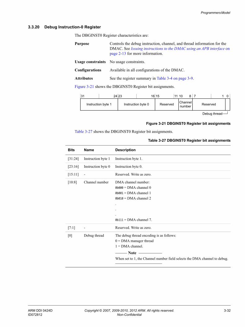
Programmers Model
3.3.20 Debug Instruction-0 Register
The DBGINST0 Register characteristics are:
Purpose Controls the debug instruction, channel, and thread information for the DMAC. See Issuing instructions to the DMAC using an APB interface on page 2-13 for more information.
Usage constraints No usage constraints.
Configurations Available in all configurations of the DMAC.
Attributes See the register summary in Table 3-4 on page 3-9.
Figure 3-21 shows the DBGINST0 Register bit assignments.
Figure 3-21 DBGINST0 Register bit assignments
Table 3-27 shows the DBGINST0 Register bit assignments.
31 24 23 16 15 8 7 1 0
Instruction byte 1 Instruction byte 0 Channel number Reserved
Debug thread
1011
Reserved
Table 3-27 DBGINST0 Register bit assignments
Bits Name Description
[31:24] Instruction byte 1 Instruction byte 1.
[23:16] Instruction byte 0 Instruction byte 0.
[15:11] - Reserved. Write as zero.
[10:8] Channel number DMA channel number:0b000 = DMA channel 00b001 = DMA channel 10b010 = DMA channel 2...0b111 = DMA channel 7.
[7:1] - Reserved. Write as zero.
[0] Debug thread The debug thread encoding is as follows:0 = DMA manager thread1 = DMA channel.
Note When set to 1, the Channel number field selects the DMA channel to debug.
ARM DDI 0424D Copyright © 2007, 2009-2010, 2012 ARM. All rights reserved. 3-32ID072812 Non-Confidential

Programmers Model
3.3.21 Debug Instruction-1 Register
The DBGINST1 Register characteristics are:
Purpose Controls the upper bytes of the debug instruction for the DMAC. See Issuing instructions to the DMAC using an APB interface on page 2-13 for more information.
Usage constraints No usage constraints.
Configurations Available in all configurations of the DMAC.
Attributes See the register summary in Table 3-4 on page 3-9.
Figure 3-22 shows the DBGINST1 Register bit assignments.
Figure 3-22 DBGINST1 Register bit assignments
Table 3-28 shows the DBGINST1 Register bit assignments.
3.3.22 Configuration Register 0
The CR0 Register characteristics are:
Purpose Provides the status of the tie-off control signals. It contains the following information about the configuration of the DMAC:• The number of DMA channels that it contains.• The number of peripheral request interfaces it provides.• The number of irq signals it provides.
Usage constraints No usage constraints.
Configurations Available in all configurations of the DMAC.
Attributes See the register summary in Table 3-5 on page 3-9.
Figure 3-23 on page 3-34 shows the CR0 Register bit assignments.
31 24 23 16 15 8 7 0
Instruction byte 5 Instruction byte 4 Instruction byte 3 Instruction byte 2
Table 3-28 DBGINST1 Register bit assignments
Bits Name Description
[31:24] Instruction byte 5 Instruction byte 5
[23:16] Instruction byte 4 Instruction byte 4
[15:8] Instruction byte 3 Instruction byte 4
[7:0] Instruction byte 2 Instruction byte 2
ARM DDI 0424D Copyright © 2007, 2009-2010, 2012 ARM. All rights reserved. 3-33ID072812 Non-Confidential

Programmers Model
Figure 3-23 CR0 Register bit assignments
Table 3-29 shows the CR0 Register bit assignments.
31 16 12 11 7 6 34 2 1 0
Undefined
17
num_events Reserved
boot_en
22 21
Reservedmgr_ns_at_rst
periph_req
num_periph_req num_chnls
Table 3-29 CR0 Register bit assignments
Bits Name Description
[31:22] - Reserved, read UNDEFINED.
[21:17] num_events Number of interrupt outputs that the DMAC provides:0b00000 = 1 interrupt output, irq[0]0b00001 = 2 interrupt outputs, irq[1:0]0b00010 = 3 interrupt outputs, irq[2:0]...0b11111 = 32 interrupt outputs, irq[31:0].
[16:12] num_periph_req Number of peripheral request interfaces that the DMAC provides:0b00000 = 1 peripheral request interface0b00001 = 2 peripheral request interfaces0b00010 = 3 peripheral request interfaces...0b11111 = 32 peripheral request interfaces.
Note This field is only valid when the periph_req bit is set to 1.
[11:7] - Reserved, read UNDEFINED.
[6:4] num_chnls Number of DMA channels that the DMAC supports:0b000 = 1 DMA channel0b001 = 2 DMA channels0b010 = 3 DMA channels...0b111 = 8 DMA channels.
[3] - Reserved, read UNDEFINED.
ARM DDI 0424D Copyright © 2007, 2009-2010, 2012 ARM. All rights reserved. 3-34ID072812 Non-Confidential
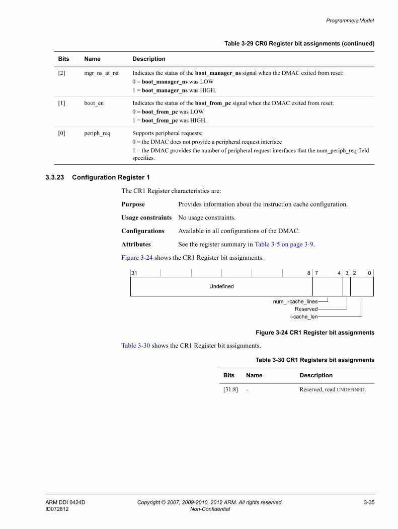
Programmers Model
3.3.23 Configuration Register 1
The CR1 Register characteristics are:
Purpose Provides information about the instruction cache configuration.
Usage constraints No usage constraints.
Configurations Available in all configurations of the DMAC.
Attributes See the register summary in Table 3-5 on page 3-9.
Figure 3-24 shows the CR1 Register bit assignments.
Figure 3-24 CR1 Register bit assignments
Table 3-30 shows the CR1 Register bit assignments.
[2] mgr_ns_at_rst Indicates the status of the boot_manager_ns signal when the DMAC exited from reset:0 = boot_manager_ns was LOW1 = boot_manager_ns was HIGH.
[1] boot_en Indicates the status of the boot_from_pc signal when the DMAC exited from reset:0 = boot_from_pc was LOW1 = boot_from_pc was HIGH.
[0] periph_req Supports peripheral requests:0 = the DMAC does not provide a peripheral request interface1 = the DMAC provides the number of peripheral request interfaces that the num_periph_req field specifies.
Table 3-29 CR0 Register bit assignments (continued)
Bits Name Description
31 8 7 4 3 2 0
Undefined
Reservednum_i-cache_lines
i-cache_len
Table 3-30 CR1 Registers bit assignments
Bits Name Description
[31:8] - Reserved, read UNDEFINED.
ARM DDI 0424D Copyright © 2007, 2009-2010, 2012 ARM. All rights reserved. 3-35ID072812 Non-Confidential

Programmers Model
3.3.24 Configuration Register 2
The CR2 Register characteristics are:
Purpose Provides the value of the boot address that boot_addr[31:0] configures.
Usage constraints No usage constraints.
Configurations Available in all configurations of the DMAC.
Attributes See the register summary in Table 3-5 on page 3-9.
Figure 3-25 shows the CR2 Register bit assignments.
Figure 3-25 CR2 Register bit assignments
Table 3-31 shows the CR2 Register bit assignments.
3.3.25 Configuration Register 3
The CR3 Register characteristics are:
Purpose Provides the security state of the event-interrupt resources that are initialized when the DMAC exits from reset.
[7:4] num_i-cache_lines Number of i-cache lines:0b0000 = 1 i-cache line0b0001 = 2 i-cache lines0b0010 = 3 i-cache lines...0b1111 = 16 i-cache lines.
[3] - Reserved, read UNDEFINED.
[2:0] i-cache_len The length of an i-cache line:0b000-0b001 = reserved0b010 = 4 bytes0b011 = 8 bytes0b100 = 16 bytes0b101 = 32 bytes0b110-0b111 = reserved.
Table 3-30 CR1 Registers bit assignments (continued)
Bits Name Description
31 0
boot_addr
Table 3-31 CR2 Register bit assignments
Bits Name Description
[31:0] boot_addr Provides the value of boot_addr[31:0] when the DMAC exited from reset
ARM DDI 0424D Copyright © 2007, 2009-2010, 2012 ARM. All rights reserved. 3-36ID072812 Non-Confidential

Programmers Model
Usage constraints No usage constraints.
Configurations Available in all configurations of the DMAC.
Attributes See the register summary in Table 3-5 on page 3-9.
Figure 3-26 shows the CR3 Register bit assignments.
Figure 3-26 CR3 Register bit assignments
Table 3-32 shows the CR3 Register bit assignments.
3.3.26 Configuration Register 4
The CR4 Register characteristics are:
Purpose Provides the security state of the peripheral request interfaces that is initialized when the DMAC exits from reset.
Usage constraints No usage constraints.
Configurations Available in all configurations of the DMAC.
Attributes See the register summary in Table 3-5 on page 3-9.
Figure 3-27 on page 3-38 shows the CR4 Register bit assignments.
31 30 29 28 27 26 25 24 23 22 21 20 19 18 17 16 15 14 13 12 11 10 9 8 7 6 5 4 3 2 1 0
.
.
.
INS forevent-interrupt[0]INS forevent-interrupt[1]INS forevent-interrupt[2]
INS forevent-interrupt[31]
Table 3-32 CR3 Register bit assignments
Bits Name Description
[31a:0] INS Provides the security state of an event-interrupt resource:Bit [N] = 0 Event<N> or irq[N] is in the Secure state.Bit [N] = 1 Event<N> or irq[N] is in the Non-secure state.
Note The boot_irq_ns[x:0] signals initialize the bits in this register when the DMAC exits from reset. See Table A-12 on page A-9 for more information.
a. If you configure the DMAC to provide fewer than 32 event-interrupt resources then the upper bits are UNDEFINED and RAZ.
ARM DDI 0424D Copyright © 2007, 2009-2010, 2012 ARM. All rights reserved. 3-37ID072812 Non-Confidential

Programmers Model
Figure 3-27 CR4 Register bit assignments
Table 3-33 shows the CR4 Register bit assignments.
3.3.27 DMA Configuration Register
The CRD Register characteristics are:
Purpose Provides information about the configuration of the data buffer, data width, and read and write issuing capability of the DMAC.
Usage constraints No usage constraints.
Configurations Available in all configurations of the DMAC.
Attributes See the register summary in Table 3-5 on page 3-9.
Figure 3-28 shows the CRD Register bit assignments.
Figure 3-28 CRD Register bit assignments
31 30 29 28 27 26 25 24 23 22 21 20 19 18 17 16 15 14 13 12 11 10 9 8 7 6 5 4 3 2 1 0
.
.
.
PNS forPRPHL_REQ 0PNS for PRPHL_REQ 1PNS forPRPHL_REQ 2
PNS forPRPHL_REQ 31
Table 3-33 CR4 Register bit assignments
Bits Name Description
[31a:0] PNS Provides the security state of the peripheral request interfaces:Bit [N] = 0 Peripheral request interface N is in the Secure state.Bit [N] = 1 Peripheral request interface N is in the Non-secure state.
Note The boot_periph_ns tie-off signals initialize the bits in this register when the DMAC exits from reset. See Table A-12 on page A-9 for more information.
a. If you configure the DMAC to provide fewer than 32 peripheral request interfaces, the upper bits are UNDEFINED and RAZ.
31 16 15 8 7 6 4 3 2 0
Undefined
data_buffer_dep
Reserved Reserved
data_width
30 29 20 19 14
wr_q_deprd_q_dep
Reserved
12 11
wr_caprd_cap
ARM DDI 0424D Copyright © 2007, 2009-2010, 2012 ARM. All rights reserved. 3-38ID072812 Non-Confidential
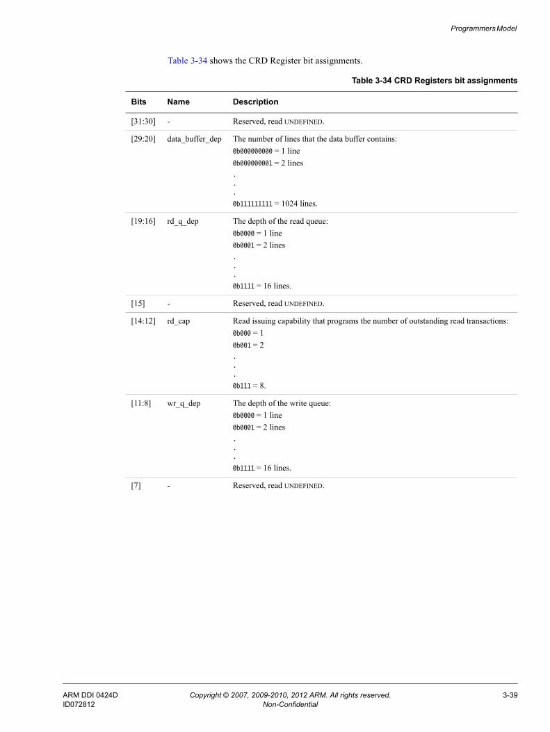
Programmers Model
Table 3-34 shows the CRD Register bit assignments.
Table 3-34 CRD Registers bit assignments
Bits Name Description
[31:30] - Reserved, read UNDEFINED.
[29:20] data_buffer_dep The number of lines that the data buffer contains:0b000000000 = 1 line0b000000001 = 2 lines...
0b111111111 = 1024 lines.
[19:16] rd_q_dep The depth of the read queue:0b0000 = 1 line0b0001 = 2 lines...
0b1111 = 16 lines.
[15] - Reserved, read UNDEFINED.
[14:12] rd_cap Read issuing capability that programs the number of outstanding read transactions:0b000 = 10b001 = 2...
0b111 = 8.
[11:8] wr_q_dep The depth of the write queue:0b0000 = 1 line0b0001 = 2 lines...
0b1111 = 16 lines.
[7] - Reserved, read UNDEFINED.
ARM DDI 0424D Copyright © 2007, 2009-2010, 2012 ARM. All rights reserved. 3-39ID072812 Non-Confidential

Programmers Model
3.3.28 Watchdog Register
The WD Register characteristics are:
Purpose Controls the watchdog behavior.
Usage constraints ARM recommends that you only update this register when all the DMA channel threads are in the Stopped state.
Configurations Available in all configurations of the DMAC.
Attributes See the register summary in Table 3-5 on page 3-9.
Figure 3-29 shows the WD Register bit assignments.
Figure 3-29 WD Register bit assignments
Table 3-35 shows the WD Register bit assignments.
[6:4] wr_cap Write issuing capability that programs the number of outstanding write transactions:0b000 = 10b001 = 2...
0b111 = 8.
[3] - Reserved, read UNDEFINED.
[2:0] data_width The data bus width of the AXI master interface:0b000 = reserved0b001 = reserved0b010 = 32-bit0b011 = 64-bit0b100 = 128-bit0b101-0b111 = reserved.
Table 3-34 CRD Registers bit assignments (continued)
Bits Name Description
31 1 0
wd_irq_only
Reserved
Table 3-35 WD Register bit assignments
Bits Name Description
[31:1] - Reserved, read UNDEFINED.
[0] wd_irq_only Controls how the DMAC responds when it detects a lock-up condition:0 = the DMAC aborts all of the contributing DMA channels and sets irq_abort HIGH1 = the DMAC sets irq_abort HIGH. See Watchdog abort on page 2-26 for more information.
ARM DDI 0424D Copyright © 2007, 2009-2010, 2012 ARM. All rights reserved. 3-40ID072812 Non-Confidential

Programmers Model
3.3.29 Peripheral Identification Registers
The periph_id_[3:0] Register characteristics are:
Purpose Provides information about the configuration and version of the peripheral.
Usage constraints No usage constraints.
Configurations Available in all configurations of the DMAC.
Attributes See the register summary in Table 3-6 on page 3-10.
These registers can conceptually be treated as a single register that holds a 32-bit peripheral ID value. Figure 3-30 shows the correspondence between bits [7:0] of the periph_id registers and the conceptual 32-bit Peripheral ID Register.
Figure 3-30 periph_id Register bit assignments
Table 3-36 shows the bit assignments for the conceptual 32-bit peripheral ID register.
The following subsections describe the periph_id registers:• Peripheral Identification Register 0 on page 3-42.• Peripheral Identification Register 1 on page 3-42.• Peripheral Identification Register 2 on page 3-42.• Peripheral Identification Register 3 on page 3-43.
31 24 23 16 15 8 7 0
7 0 7 4 3 0 7 4 3 0 7 0
periph_id_0
revision
designer part number
designer_1 designer_0 part_ number_1 part_ number_0Reserved
periph_id_1periph_id_2periph_id_3
Conceptual 32-bit Peripheral ID register
1
integration_cfg
Table 3-36 Conceptual peripheral ID register bit assignments
Bits Name Description
[31:25] - Reserved, read UNDEFINED.
[24] integration_cfg Identifies if the DMAC contains integration test logic. See Table 3-40 on page 3-43.
[23:20] revision Identifies the RTL revision of the peripheral. See Table 3-39 on page 3-42.
[19:12] designer Identifies the designer. This is 0x41 for ARM.
[11:0] part_number Identifies the peripheral. The part number for the DMAC is 0x330.
ARM DDI 0424D Copyright © 2007, 2009-2010, 2012 ARM. All rights reserved. 3-41ID072812 Non-Confidential
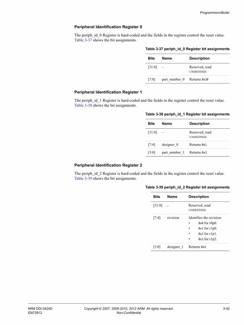
Programmers Model
Peripheral Identification Register 0
The periph_id_0 Register is hard-coded and the fields in the register control the reset value. Table 3-37 shows the bit assignments.
Peripheral Identification Register 1
The periph_id_1 Register is hard-coded and the fields in the register control the reset value. Table 3-38 shows the bit assignments.
Peripheral Identification Register 2
The periph_id_2 Register is hard-coded and the fields in the register control the reset value. Table 3-39 shows the bit assignments.
Table 3-37 periph_id_0 Register bit assignments
Bits Name Description
[31:8] - Reserved, read UNDEFINED
[7:0] part_number_0 Returns 0x30
Table 3-38 periph_id_1 Register bit assignments
Bits Name Description
[31:8] - Reserved, read UNDEFINED
[7:4] designer_0 Returns 0x1
[3:0] part_number_1 Returns 0x3
Table 3-39 periph_id_2 Register bit assignments
Bits Name Description
[31:8] - Reserved, read UNDEFINED.
[7:4] revision Identifies the revision:• 0x0 for r0p0.• 0x1 for r1p0.• 0x2 for r1p1.• 0x3 for r1p2.
[3:0] designer_1 Returns 0x4.
ARM DDI 0424D Copyright © 2007, 2009-2010, 2012 ARM. All rights reserved. 3-42ID072812 Non-Confidential

Programmers Model
Peripheral Identification Register 3
The periph_id_3 Register is hard-coded and the fields in the register control the reset value. Table 3-40 shows the bit assignments.
3.3.30 Component Identification Registers 0-3
The pcell_id_[3:0] Register characteristics are:
Purpose When concatenated, these four registers return 0xB105F00D.
Usage constraints No usage constraints.
Configurations Available in all configurations of the DMAC.
Attributes See the register summary in Table 3-6 on page 3-10.
These registers can be treated conceptually as a single register that holds a 32-bit component identification value. You can use the register for automatic BIOS configuration.
Figure 3-31 shows the register bit assignments.
Figure 3-31 pcell_id Register bit assignments
Table 3-41 shows the register bit assignments.
Table 3-40 periph_id_3 Register bit assignments
Bits Name Description
[31:8] - Reserved, read UNDEFINED
[7:1] - Reserved for future use, read UNDEFINED
[0] integration_cfg Returns 0 to indicate that the DMAC does not contain integration test logic
7 0 7 0 7 0 7 0
Conceptual 32-bit component ID register
31 24 23 16 15 8 7 0
0x0D0xF00x050xB1
pcell_id_3 pcell_id_2 pcell_id_1 pcell_id_0
Table 3-41 pcell_id Register bit assignments
Conceptual 32-bit component ID register pcell_id_[3:0] Registers
Bits Reset value Register Bits Description
[31:24] 0xB1
pcell_id_3 [31:8] Read UNDEFINED
[7:0] Returns 0xB1
[23:16] 0x05
pcell_id_2 [31:8] Read UNDEFINED
[7:0] Returns 0x05
ARM DDI 0424D Copyright © 2007, 2009-2010, 2012 ARM. All rights reserved. 3-43ID072812 Non-Confidential

Programmers Model
[15:8] 0xF0
pcell_id_1 [31:8] Read UNDEFINED
[7:0] Returns 0xF0
[7:0] 0x0D
pcell_id_0 [31:8] Read UNDEFINED
[7:0] Returns 0x0D
Table 3-41 pcell_id Register bit assignments (continued)
Conceptual 32-bit component ID register pcell_id_[3:0] Registers
Bits Reset value Register Bits Description
ARM DDI 0424D Copyright © 2007, 2009-2010, 2012 ARM. All rights reserved. 3-44ID072812 Non-Confidential

Chapter 4 Instruction Set
This chapter describes the instruction set of the DMAC. It contains the following sections:• Instruction syntax conventions on page 4-2.• Instruction set summary on page 4-3.• Instructions on page 4-4.• Assembler directives on page 4-21.
ARM DDI 0424D Copyright © 2007, 2009-2010, 2012 ARM. All rights reserved. 4-1ID072812 Non-Confidential

Instruction Set
4.1 Instruction syntax conventionsThe following conventions are used in assembler syntax prototype lines and their subfields:
< > Any item bracketed by < and > is mandatory. A description of the item and of how it is encoded in the instruction is supplied by subsequent text.
[ ] Any item bracketed by [ and ] is optional. A description of the item and of how its presence or absence is encoded in the instruction is supplied by subsequent text.
spaces Single spaces are used for clarity, to separate items. When a space is obligatory in the assembler syntax, two or more consecutive spaces are used.
ARM DDI 0424D Copyright © 2007, 2009-2010, 2012 ARM. All rights reserved. 4-2ID072812 Non-Confidential
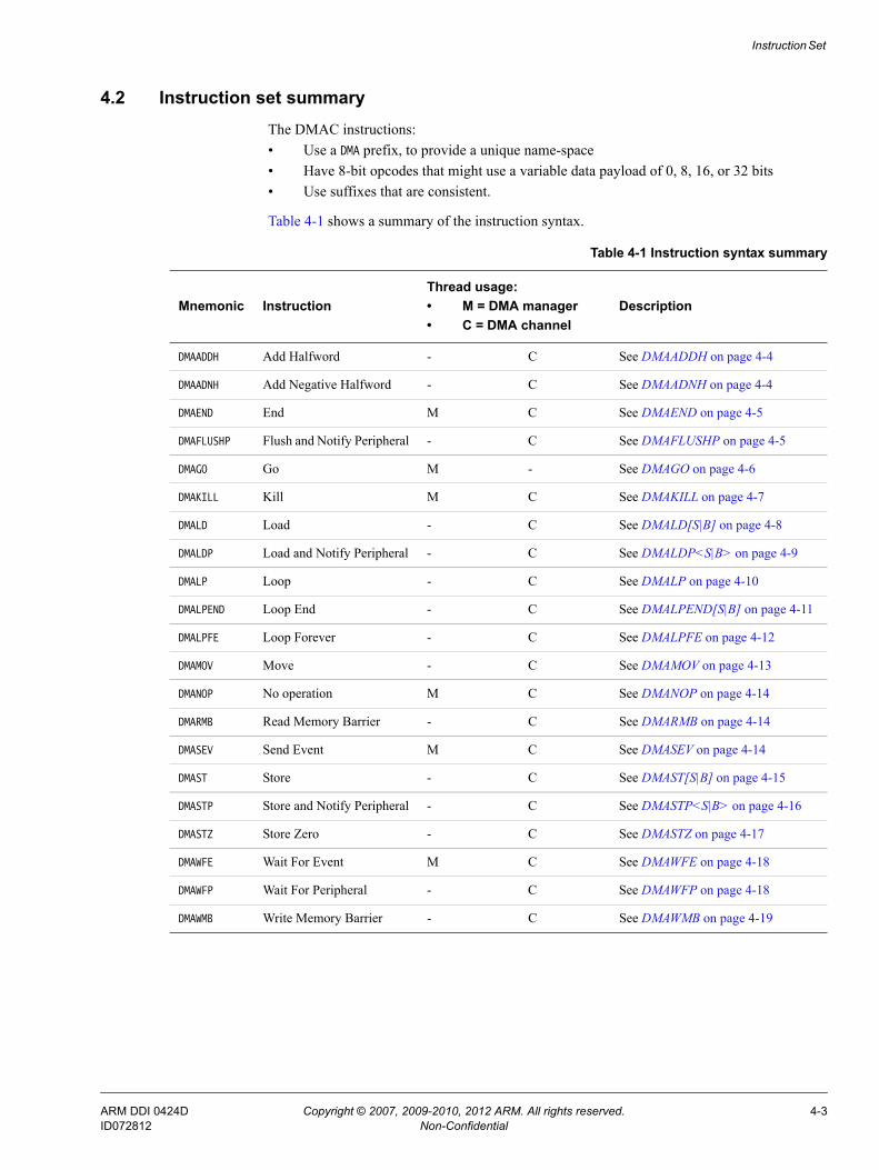
Instruction Set
4.2 Instruction set summaryThe DMAC instructions:• Use a DMA prefix, to provide a unique name-space• Have 8-bit opcodes that might use a variable data payload of 0, 8, 16, or 32 bits• Use suffixes that are consistent.
Table 4-1 shows a summary of the instruction syntax.
Table 4-1 Instruction syntax summary
Mnemonic InstructionThread usage:• M = DMA manager• C = DMA channel
Description
DMAADDH Add Halfword - C See DMAADDH on page 4-4
DMAADNH Add Negative Halfword - C See DMAADNH on page 4-4
DMAEND End M C See DMAEND on page 4-5
DMAFLUSHP Flush and Notify Peripheral - C See DMAFLUSHP on page 4-5
DMAGO Go M - See DMAGO on page 4-6
DMAKILL Kill M C See DMAKILL on page 4-7
DMALD Load - C See DMALD[S|B] on page 4-8
DMALDP Load and Notify Peripheral - C See DMALDP<S|B> on page 4-9
DMALP Loop - C See DMALP on page 4-10
DMALPEND Loop End - C See DMALPEND[S|B] on page 4-11
DMALPFE Loop Forever - C See DMALPFE on page 4-12
DMAMOV Move - C See DMAMOV on page 4-13
DMANOP No operation M C See DMANOP on page 4-14
DMARMB Read Memory Barrier - C See DMARMB on page 4-14
DMASEV Send Event M C See DMASEV on page 4-14
DMAST Store - C See DMAST[S|B] on page 4-15
DMASTP Store and Notify Peripheral - C See DMASTP<S|B> on page 4-16
DMASTZ Store Zero - C See DMASTZ on page 4-17
DMAWFE Wait For Event M C See DMAWFE on page 4-18
DMAWFP Wait For Peripheral - C See DMAWFP on page 4-18
DMAWMB Write Memory Barrier - C See DMAWMB on page 4-19
ARM DDI 0424D Copyright © 2007, 2009-2010, 2012 ARM. All rights reserved. 4-3ID072812 Non-Confidential

Instruction Set
4.3 InstructionsThe following sections describe the instructions that a DMAC can execute.
4.3.1 DMAADDH
Add Halfword adds an immediate 16-bit value to the SARn Register or DARn Register, for the DMA channel thread. This enables the DMAC to support 2D DMA operations. See Source Address Registers on page 3-23 and Destination Address Registers on page 3-24.
Note The immediate unsigned 16-bit value is zero-extended before the DMAC adds it to the address, using 32-bit addition. The DMAC discards the carry bit so that addresses wrap from 0xFFFFFFFF to 0x00000000.
Figure 4-1 shows the instruction encoding.
Figure 4-1 DMAADDH encoding
Assembler syntax
DMAADDH <address_register>, <16-bit immediate>
where:
<address_register> Selects the address register to use. It must be either:SAR SARn Register and sets ra to 0.DAR DARn Register and sets ra to 1.
<16-bit immediate> The immediate value to be added to the <address_register>.
Operation
You can only use this instruction in a DMA channel thread.
4.3.2 DMAADNH
Add Negative Halfword adds an immediate negative 16-bit value to the SARn Register or DARn Register, for the DMA channel thread. This enables the DMAC to support 2D DMA operations, or reading or writing an area of memory in a different order to naturally incrementing addresses. See Source Address Registers on page 3-23 and Destination Address Registers on page 3-24.
Note The immediate unsigned 16-bit value is one-extended to 32 bits, to create a value that is the two’s complement representation of a negative number between -65536 and -1, before the DMAC adds it to the address using 32-bit addition. The DMAC discards the carry bit so that addresses wrap from 0xFFFFFFFF to 0x00000000. The net effect is to subtract between 65536 and 1 from the current value in the Source or Destination Address Register.
Figure 4-2 on page 4-5 shows the instruction encoding.
0
7 6 5 4 3 2 1 0
0 1 0 1 0 1 ra
15 8 7
imm[7:0]
23 16
imm[15:8]
ARM DDI 0424D Copyright © 2007, 2009-2010, 2012 ARM. All rights reserved. 4-4ID072812 Non-Confidential

Instruction Set
Figure 4-2 DMAADNH encoding
Assembler syntax
DMAADNH <address_register>, <16-bit immediate>
where:
<address_register> Selects the address register to use. It must be either:SAR SARn Register and sets ra to 0.DAR DARn Register and sets ra to 1.
<16-bit immediate> The immediate value to be added to the <address_register>.
Note You must specify the 16-bit immediate as the number that is to be
represented in the instruction encoding. For example, DMAADNH DAR, 0xFFF0 causes the value 0xFFFFFFF0 to be added to the current value of the Destination Address Register, effectively subtracting 16 from the DAR.
Operation
You can only use this instruction in a DMA channel thread.
4.3.3 DMAEND
End signals to the DMAC that the DMA sequence is complete. After all DMA transfers are complete for the DMA channel, the DMAC moves the channel to the Stopped state. It also flushes data from the MFIFO and invalidates all cache entries for the thread.
Figure 4-3 shows the instruction encoding.
Figure 4-3 DMAEND encoding
Assembler syntax
DMAEND
Operation
You can use the instruction with the DMA manager thread and the DMA channel thread.
4.3.4 DMAFLUSHP
Flush Peripheral clears the state in the DMAC that describes the contents of the peripheral and sends a message to the peripheral to resend its level status.
0
7 6 5 4 3 2 1 0
0 1 0 1 1 1 ra
15 8 7
imm[7:0]
23 16
imm[15:8]
0
7 6 5 4 3 2 1 0
0 0 0 0 0 0 0
ARM DDI 0424D Copyright © 2007, 2009-2010, 2012 ARM. All rights reserved. 4-5ID072812 Non-Confidential

Instruction Set
Figure 4-4 shows the instruction encoding.
Figure 4-4 DMAFLUSHP encoding
Assembler syntax
DMAFLUSHP <peripheral>
where:
<peripheral> 5-bit immediate, value 0-31.
Operation
You can only use this instruction in a DMA channel thread.
4.3.5 DMAGO
When the DMA manager executes Go for a DMA channel that is in the Stopped state, it performs the following steps on the DMA channel:• Moves a 32-bit immediate into the program counter.• Sets its security state.• Updates it to the Executing state.
Note If a DMA channel is not in the Stopped state when the DMA manager executes DMAGO then the DMAC does not execute DMAGO but instead it executes DMANOP.
Figure 4-5 shows the instruction encoding.
Figure 4-5 DMAGO encoding
Assembler syntax
DMAGO <channel_number>, <32-bit_immediate> [, ns]
where:
<channel_number> Selects a DMA channel. It must be one of:C0 DMA channel 0.C1 DMA channel 1.
1
7 6 5 4 3 2 1 0
0 0 1 1 0 1 0
15 11 10 9 8 7
periph[4:0] 0 00
0
7 6 5 4 3 2 1 0
1 0 1 0 0 0 ns
15 14 13 12 11 10 8 7
cn[2:0]0 000 0
1647
imm[31:0]
ARM DDI 0424D Copyright © 2007, 2009-2010, 2012 ARM. All rights reserved. 4-6ID072812 Non-Confidential

Instruction Set
C2 DMA channel 2.C3 DMA channel 3.C4 DMA channel 4.C5 DMA channel 5.C6 DMA channel 6.C7 DMA channel 7.
Note If you provide a channel number that is not available for your
configuration of the DMAC, the DMA manager thread aborts.
<32-bit_immediate> The immediate value that is written to the CPCn Register for the selected <channel_number>. See Channel Program Counter Registers on page 3-23.
[ns] • If ns is present, the DMA channel operates in the Non-secure state.• Otherwise, the execution of the instruction depends on the security
state of the DMA manager:DMA manager is in the Secure state
DMA channel operates in the Secure state.DMA manager is in the Non-secure state
The DMAC aborts.
Operation
You can only use this instruction with the DMA manager thread.
4.3.6 DMAKILL
Kill instructs the DMAC to immediately terminate execution of a thread. Depending on the thread type, the DMAC performs the following steps:
DMA manager thread 1. Invalidates all cache entries for the DMA manager.2. Moves the DMA manager to the Stopped state.
DMA channel thread 1. Moves the DMA channel to the Killing state.2. Waits for AXI transactions, with an ID equal to the DMA channel number,
to complete.3. Invalidates all cache entries for the DMA channel.4. Remove all entries in the MFIFO for the DMA channel.5. Remove all entries in the read buffer queue and write buffer queue for the
DMA channel.6. Moves the DMA channel to the Stopped state.
Figure 4-6 shows the instruction encoding.
Figure 4-6 DMAKILL encoding
1
7 6 5 4 3 2 1 0
0 0 0 0 0 0 0
ARM DDI 0424D Copyright © 2007, 2009-2010, 2012 ARM. All rights reserved. 4-7ID072812 Non-Confidential

Instruction Set
Assembler syntax
DMAKILL
Operation
You can use the instruction with the DMA manager thread and the DMA channel thread.
Note You must not use the DMAKILL instruction in DMA channel programs. To issue a DMAKILL instruction, use the DBGINST0 Register. See Debug Instruction-0 Register on page 3-32.
4.3.7 DMALD[S|B]
Load instructs the DMAC to perform a DMA load, using AXI transactions that the Source Address Registers on page 3-23 and Channel Control Registers on page 3-25 specify. It places the read data into the MFIFO and tags it with the corresponding channel number. DMALD is an unconditional instruction but DMALDS and DMALDB are conditional on the state of the request_type flag. If the src_inc bit in the Channel Control Registers on page 3-25 is set to incrementing, the DMAC updates the Source Address Registers on page 3-23 after it executes DMALD[S|B].
Note The DMAC sets the value of request_type when it executes a DMAWFP instruction. See DMAWFP on page 4-18.
Figure 4-7 shows the instruction encoding.
Figure 4-7 DMALD[S|B] encoding
Assembler syntax
DMALD[S|B]
where:
[S] If S is present, the assembler sets bs to 0 and x to 1. The instruction is conditional on the state of the request_type flag:request_type = Single
The DMAC performs a DMALD instruction and it sets arlen[3:0]=0x0 so that the AXI read transaction length is one. The DMAC ignores the value of the src_burst_len field in the Channel Control Registers on page 3-25.
request_type = Burst The DMAC performs a DMANOP instruction. The DMAC increments the channel PC to the next instruction. No state change occurs.
x
7 6 5 4 3 2 1 0
0 0 0 0 0 1 bs
ARM DDI 0424D Copyright © 2007, 2009-2010, 2012 ARM. All rights reserved. 4-8ID072812 Non-Confidential

Instruction Set
[B] If B is present, the assembler sets bs to 1 and x to 1. The instruction is conditional on the state of the request_type flag:request_type = Single
The DMAC performs a DMANOP instruction. The DMAC increments the channel PC to the next instruction. No state change occurs.
request_type = Burst The DMAC performs a DMALD instruction.
If you do not specify the S or B operand, the assembler sets bs to 0 and x to 0, and the DMAC always executes a DMA load.
Operation
You can only use this instruction in a DMA channel thread. If you specify the S or B operand, execution of the instruction is conditional on the state of request_type matching that of the instruction. See Assembler syntax on page 4-8.
4.3.8 DMALDP<S|B>
Load and notify Peripheral instructs the DMAC to perform a DMA load, using AXI transactions that Source Address Registers on page 3-23 and Channel Control Registers on page 3-25 specify. It places the read data into a FIFO that is tagged with the corresponding channel number and after it receives the last data item, it updates datype[1:0] to indicate to the peripheral that the data transfer is complete. If the src_inc bit in the Channel Control Registers on page 3-25 is set to incrementing, the DMAC updates Source Address Registers on page 3-23 after it executes DMALDP<S|B>.
Figure 4-8 shows the instruction encoding.
Figure 4-8 DMALDP<S|B> encoding
Assembler syntax
DMALDP<S|B> <peripheral>
where:
<S> When S is present, the assembler sets bs to 0. The instruction is conditional on the state of the request_type flag:request_type = Single
The DMAC performs a DMALDP instruction and it sets arlen[3:0]=0x0 so that the AXI read transaction length is one. The DMAC ignores the value of the src_burst_len field in the Channel Control Registers on page 3-25.
request_type = Burst The DMAC performs a DMANOP.
1
7 6 5 4 3 2 1 0
0 0 1 0 0 1 bs
15 11 10 9 8 7
periph[4:0] 0 00
ARM DDI 0424D Copyright © 2007, 2009-2010, 2012 ARM. All rights reserved. 4-9ID072812 Non-Confidential

Instruction Set
<B> When B is present, the assembler sets bs to 1. The instruction is conditional on the state of the request_type flag:request_type = Single
The DMAC performs a DMANOP.request_type = Burst
The DMAC performs a load using a burst DMA transfer.
<peripheral> 5-bit immediate, value 0-31.
Note The DMAC sets the value of the request_type flag when it executes a DMAWFP instruction. See DMAWFP on page 4-18.
Operation
You can only use this instruction in a DMA channel thread. Execution of the instruction is conditional on the state of the request_type flag matching that of the instruction. See Assembler syntax on page 4-9.
4.3.9 DMALP
Loop instructs the DMAC to load an 8-bit value into the Loop Counter Register you specify. This instruction indicates the start of a section of instructions, and you set the end of the section using the DMALPEND instruction. See DMALPEND[S|B] on page 4-11. The DMAC repeats the set of instructions that you insert between DMALP and DMALPEND until the value in the Loop Counter Register reaches zero.
Note The DMAC saves the value of the PC for the instruction that follows DMALP. After the DMAC executes DMALPEND, and the Loop Counter Register is not zero, this enables it to execute the first instruction in the loop.
Figure 4-9 shows the instruction encoding.
Figure 4-9 DMALP encoding
Assembler syntax
DMALP <loop_iterations>
where:
<loop_iterations>
Specifies the number of loops to perform, range 1-256.
0
7 6 5 4 3 2 1 0
0 0 1 0 0 0 lc
15 8 7
iter[7:0]
ARM DDI 0424D Copyright © 2007, 2009-2010, 2012 ARM. All rights reserved. 4-10ID072812 Non-Confidential

Instruction Set
Note The assembler determines the Loop Counter Register to use and either:
• Sets lc to 0, and the DMAC writes the value loop_iterations minus 1 to the Loop Counter 0 Registers on page 3-29.
• Sets lc to 1, and the DMAC writes the value loop_iterations minus 1 to the Loop Counter 1 Registers on page 3-30.
Operation
You can only use this instruction in a DMA channel thread.
4.3.10 DMALPEND[S|B]
Loop End indicates the last instruction in the program loop but the behavior of the DMAC depends on whether DMALP or DMALPFE starts the loop. If a loop starts with:
DMALP The loop has a defined loop count and DMALPEND[S|B] instructs the DMAC to read the value of the Loop Counter Register. If a Loop Counter Register returns:Zero The DMAC executes a DMANOP and therefore exits the loop.Non-zero The DMAC decrements the value in the Loop Counter Register and
updates the thread PC to contain the address of the first instruction in the program loop, that is, the instruction that follows the DMALP.
DMALPFE The loop has an undefined loop count and the DMAC uses the state of the request_last flag to control when it exits the loop. If the request_last flag is:0 The DMAC updates the thread PC to contain the address of the first
instruction in the program loop, that is, the instruction that follows the DMALP.
1 The DMAC executes a DMANOP and therefore exits the loop.
Figure 4-10 shows the instruction encoding.
Figure 4-10 DMALPEND[S|B] encoding
Assembler syntax
DMALPEND[S|B]
where:
[S] If S is present and the loop starts with DMALP, then the assembler sets bs to 0 and x to 1. The instruction is conditional on the state of the request_type flag:request_type = Single
The DMAC executes the DMALPEND instruction.request_type = Burst
The DMAC performs a DMANOP and therefore exits the loop.
x
7 6 5 4 3 2 1 0
0 0 1 nf 1 lc bs
15 8 7
backwards_jump[7:0]
ARM DDI 0424D Copyright © 2007, 2009-2010, 2012 ARM. All rights reserved. 4-11ID072812 Non-Confidential

Instruction Set
[B] If B is present and the loop starts with DMALP, then the assembler sets bs to 1 and x to 1. The instruction is conditional on the state of the request_type flag:request_type = Single
The DMAC performs a DMANOP and therefore exits the loop.request_type = Burst
The DMAC executes the DMALPEND instruction.
If you do not specify the S or B operand, the assembler sets bs to 0 and x to 0, and the DMAC always executes the DMALPEND instruction.
Note You must not specify the S or B operand when a loop starts with DMALPFE. If you do, the assembler issues a warning message and sets bs to 0, x to 0, and nf to 1. In the same way as for DMALPFE, the DMAC uses the state of the request_last flag to control when it exits the loop.
Note The DMAC sets the value of the:
• request_type flag when it executes a DMAWFP instruction. See DMAWFP on page 4-18.
• request_last flag to 1 when the corresponding peripheral sets drlast HIGH, to signal the last peripheral request. See Peripheral length management on page 2-17 for more information.
To correctly assign the additional bits in the DMALPEND instruction, that Figure 4-10 on page 4-11 shows, the assembler determines the values for:
backwards_jump[7:0] Sets the relative location of the first instruction in the program loop. The assembler calculates the value for backwards_jump[7:0] by subtracting the address of the first instruction in the loop from the address of the DMALPEND instruction.
nf Sets it to:• 0 if DMALPFE started the program loop.• 1 if DMALP started the program loop.
lc Sets it to:• 0 if the Loop Counter 0 Registers on page 3-29 contains the loop
counter value.• 1 if the Loop Counter 1 Registers on page 3-30 contains the loop
counter value.• 1 if DMALPFE started the program loop.
Operation
You can only use this instruction in a DMA channel thread. If you specify the S or B operand, execution of the instruction is conditional on the state of the request_type flag matching that of the instruction. See Assembler syntax on page 4-11.
4.3.11 DMALPFE
The assembler uses Loop Forever to configure certain bits in DMALPEND. See DMALPEND[S|B] on page 4-11.
ARM DDI 0424D Copyright © 2007, 2009-2010, 2012 ARM. All rights reserved. 4-12ID072812 Non-Confidential
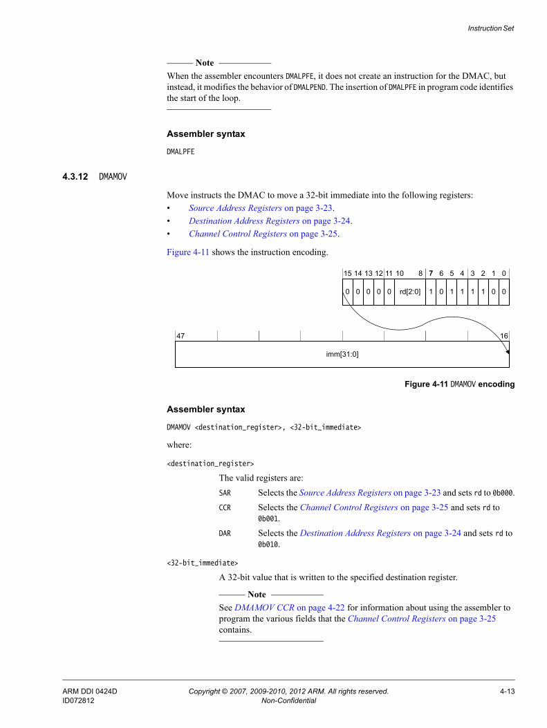
Instruction Set
Note When the assembler encounters DMALPFE, it does not create an instruction for the DMAC, but instead, it modifies the behavior of DMALPEND. The insertion of DMALPFE in program code identifies the start of the loop.
Assembler syntax
DMALPFE
4.3.12 DMAMOV
Move instructs the DMAC to move a 32-bit immediate into the following registers:• Source Address Registers on page 3-23.• Destination Address Registers on page 3-24.• Channel Control Registers on page 3-25.
Figure 4-11 shows the instruction encoding.
Figure 4-11 DMAMOV encoding
Assembler syntax
DMAMOV <destination_register>, <32-bit_immediate>
where:
<destination_register>
The valid registers are:SAR Selects the Source Address Registers on page 3-23 and sets rd to 0b000.CCR Selects the Channel Control Registers on page 3-25 and sets rd to
0b001.DAR Selects the Destination Address Registers on page 3-24 and sets rd to
0b010.
<32-bit_immediate>
A 32-bit value that is written to the specified destination register.
Note See DMAMOV CCR on page 4-22 for information about using the assembler to
program the various fields that the Channel Control Registers on page 3-25 contains.
0
7 6 5 4 3 2 1 0
1 0 1 1 1 1 0
15 14 13 12 11 10 8 7
rd[2:0]0 000 0
1647
imm[31:0]
ARM DDI 0424D Copyright © 2007, 2009-2010, 2012 ARM. All rights reserved. 4-13ID072812 Non-Confidential

Instruction Set
Operation
You can only use this instruction in a DMA channel thread.
4.3.13 DMANOP
No Operation does nothing. You can use this instruction for code alignment purposes.
Figure 4-12 shows the instruction encoding.
Figure 4-12 DMANOP encoding
Assembler syntax
DMANOP
Operation
You can use the instruction with the DMA manager thread and the DMA channel thread.
4.3.14 DMARMB
Read Memory Barrier forces the DMA channel to wait until all of the executed DMALD instructions for that channel have been issued on the AXI master interface and have completed. This enables write-after-read sequences to the same address location with no hazards.
Figure 4-13 shows the instruction encoding.
Figure 4-13 DMARMB encoding
Assembler syntax
DMARMB
Operation
You can only use this instruction in a DMA channel thread.
4.3.15 DMASEV
Send Event instructs the DMAC to modify an event-interrupt resource. Depending on how you program the Interrupt Enable Register on page 3-13, this either:
• Generates event <event_num>.
0
7 6 5 4 3 2 1 0
0 0 0 1 1 0 0
0
7 6 5 4 3 2 1 0
0 0 0 1 0 0 1
ARM DDI 0424D Copyright © 2007, 2009-2010, 2012 ARM. All rights reserved. 4-14ID072812 Non-Confidential

Instruction Set
Note Typically, you use DMAWFE to stall a thread and then another thread executes DMASEV, using
the appropriate event number, to unstall the waiting thread. See Using an event to restart DMA channels on page 2-23.
• Signals an interrupt using irq<event_num>.
Figure 4-14 shows the instruction encoding.
Figure 4-14 DMASEV encoding
Assembler syntax
DMASEV <event_num>
where:
<event_num> 5-bit immediate, value 0-31.
Note The DMAC aborts the thread if you select an event_num that is not available for your configuration of the DMAC.
Operation
You can use the instruction with the DMA manager thread and the DMA channel thread. See Using events and interrupts on page 2-23 for more information.
4.3.16 DMAST[S|B]
Store instructs the DMAC to transfer data from the FIFO to the location that the Destination Address Registers on page 3-24 specifies, using AXI transactions that the DA Register and Channel Control Registers on page 3-25 specify. If the dst_inc bit in the Channel Control Registers on page 3-25 is set to incrementing, the DMAC updates the Destination Address Registers on page 3-24 after it executes DMAST[S|B].
Figure 4-15 shows the instruction encoding.
Figure 4-15 DMAST[S|B] encoding
Assembler syntax
DMAST[S|B]
0
7 6 5 4 3 2 1 0
0 0 1 1 0 1 0
15 8 7
event_num[4:0]
1011
0 00
9
x
7 6 5 4 3 2 1 0
0 0 0 0 1 0 bs
ARM DDI 0424D Copyright © 2007, 2009-2010, 2012 ARM. All rights reserved. 4-15ID072812 Non-Confidential

Instruction Set
where:
[S] If S is present, the assembler sets bs to 0 and x to 1. The instruction is conditional on the state of the request_type flag:request_type = Single
The DMAC performs a DMAST instruction and it sets awlen[3:0]=0x0 so that the AXI write transaction length is one. The DMAC ignores the value of the dst_burst_len field in the Channel Control Registers on page 3-25.
request_type = Burst The DMAC performs a DMANOP instruction. The DMAC increments the channel PC to the next instruction. No state change occurs.
[B] If B is present, the assembler sets bs to 1 and x to 1. The instruction is conditional on the state of the request_type flag:request_type = Single
The DMAC performs a DMANOP instruction. The DMAC increments the channel PC to the next instruction. No state change occurs.
request_type = Burst The DMAC performs a DMAST instruction.
If you do not specify the S or B operand, the assembler sets bs to 0 and x to 0, and the DMAC always executes a DMA store.
Note The DMAC sets the value of the request_type flag when it executes a DMAWFP instruction. See DMAWFP on page 4-18.
Operation
You can only use this instruction in a DMA channel thread. If you specify the S or B operand, execution of the instruction is conditional on the state of the request_type flag matching that of the instruction. See Assembler syntax on page 4-15.
The DMAC only commences the burst when the MFIFO contains all of the data necessary to complete the burst transfer.
4.3.17 DMASTP<S|B>
Store and notify Peripheral instructs the DMAC to transfer data from the FIFO to the location that the Destination Address Registers on page 3-24 specifies, using AXI transactions that the DA Register and Channel Control Registers on page 3-25 specify. It uses the DMA channel number to access the appropriate location in the FIFO. After the DMA store is complete, and the DMAC has received a buffered write response, it updates datype[1:0] to notify the peripheral that the data transfer is complete. If the dst_inc bit in the Channel Control Registers on page 3-25 is set to incrementing, the DMAC updates the Destination Address Registers on page 3-24 after it executes DMASTP<S|B>.
Figure 4-16 on page 4-17 shows the instruction encoding.
ARM DDI 0424D Copyright © 2007, 2009-2010, 2012 ARM. All rights reserved. 4-16ID072812 Non-Confidential
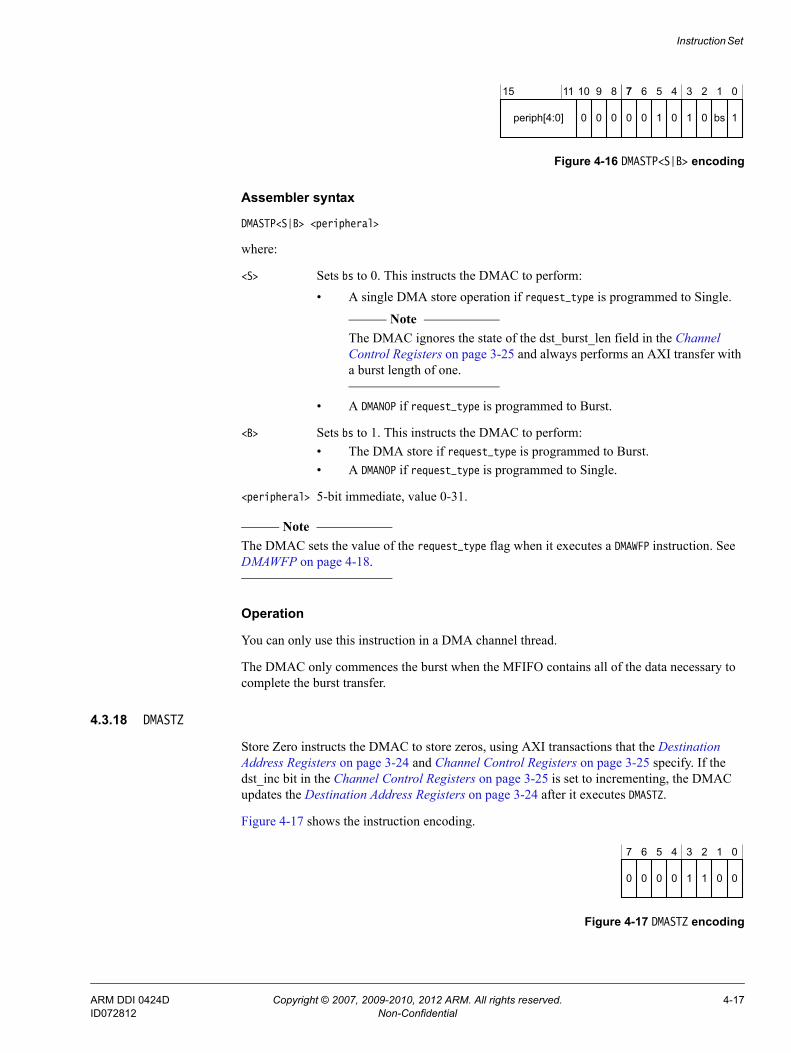
Instruction Set
Figure 4-16 DMASTP<S|B> encoding
Assembler syntax
DMASTP<S|B> <peripheral>
where:
<S> Sets bs to 0. This instructs the DMAC to perform:• A single DMA store operation if request_type is programmed to Single.
Note The DMAC ignores the state of the dst_burst_len field in the Channel
Control Registers on page 3-25 and always performs an AXI transfer with a burst length of one.
• A DMANOP if request_type is programmed to Burst.
<B> Sets bs to 1. This instructs the DMAC to perform:• The DMA store if request_type is programmed to Burst.• A DMANOP if request_type is programmed to Single.
<peripheral> 5-bit immediate, value 0-31.
Note The DMAC sets the value of the request_type flag when it executes a DMAWFP instruction. See DMAWFP on page 4-18.
Operation
You can only use this instruction in a DMA channel thread.
The DMAC only commences the burst when the MFIFO contains all of the data necessary to complete the burst transfer.
4.3.18 DMASTZ
Store Zero instructs the DMAC to store zeros, using AXI transactions that the Destination Address Registers on page 3-24 and Channel Control Registers on page 3-25 specify. If the dst_inc bit in the Channel Control Registers on page 3-25 is set to incrementing, the DMAC updates the Destination Address Registers on page 3-24 after it executes DMASTZ.
Figure 4-17 shows the instruction encoding.
Figure 4-17 DMASTZ encoding
1
7 6 5 4 3 2 1 0
0 0 1 0 1 0 bs
15 11 10 9 8 7
periph[4:0] 0 00
0
7 6 5 4 3 2 1 0
0 0 0 0 1 1 0
ARM DDI 0424D Copyright © 2007, 2009-2010, 2012 ARM. All rights reserved. 4-17ID072812 Non-Confidential

Instruction Set
Assembler syntax
DMASTZ
Operation
You can only use this instruction in a DMA channel thread.
4.3.19 DMAWFE
Wait For Event instructs the DMAC to halt execution of the thread until the event, that event_num specifies, occurs. When the event occurs, the thread moves to the Executing state and the DMAC clears the event. See Using events and interrupts on page 2-23.
Figure 4-18 shows the instruction encoding.
Figure 4-18 DMAWFE encoding
Assembler syntax
DMAWFE <event_num>[, invalid]
where:
<event_num> 5-bit immediate, value 0-31.
[invalid] Sets i to 1. If invalid is present, the DMAC invalidates the instruction cache for the current DMA thread. If invalid is not present, then the assembler sets i to 0 and the DMAC does not invalidate the instruction cache for the current DMA thread.
Note • The DMAC aborts the thread if you select an event_num that is not
available for your configuration of the DMAC.• To ensure cache coherency, you must use invalid when a processor writes
the instruction stream for a DMA channel.
Operation
You can use the instruction with the DMA manager thread and the DMA channel thread.
4.3.20 DMAWFP
Wait For Peripheral instructs the DMAC to halt execution of the thread until the specified peripheral signals a DMA request for that DMA channel.
Figure 4-19 on page 4-19 shows the instruction encoding.
0
7 6 5 4 3 2 1 0
0 0 1 1 0 1 1
15 8 7
event_num[4:0]
1011
i 00
9
ARM DDI 0424D Copyright © 2007, 2009-2010, 2012 ARM. All rights reserved. 4-18ID072812 Non-Confidential
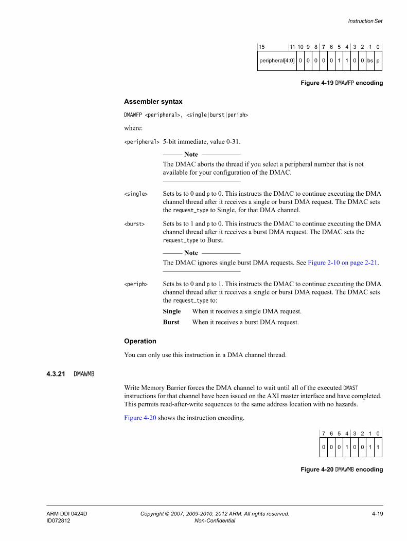
Instruction Set
Figure 4-19 DMAWFP encoding
Assembler syntax
DMAWFP <peripheral>, <single|burst|periph>
where:
<peripheral> 5-bit immediate, value 0-31.
Note The DMAC aborts the thread if you select a peripheral number that is not
available for your configuration of the DMAC.
<single> Sets bs to 0 and p to 0. This instructs the DMAC to continue executing the DMA channel thread after it receives a single or burst DMA request. The DMAC sets the request_type to Single, for that DMA channel.
<burst> Sets bs to 1 and p to 0. This instructs the DMAC to continue executing the DMA channel thread after it receives a burst DMA request. The DMAC sets the request_type to Burst.
Note The DMAC ignores single burst DMA requests. See Figure 2-10 on page 2-21.
<periph> Sets bs to 0 and p to 1. This instructs the DMAC to continue executing the DMA channel thread after it receives a single or burst DMA request. The DMAC sets the request_type to:Single When it receives a single DMA request.Burst When it receives a burst DMA request.
Operation
You can only use this instruction in a DMA channel thread.
4.3.21 DMAWMB
Write Memory Barrier forces the DMA channel to wait until all of the executed DMAST instructions for that channel have been issued on the AXI master interface and have completed. This permits read-after-write sequences to the same address location with no hazards.
Figure 4-20 shows the instruction encoding.
Figure 4-20 DMAWMB encoding
p
7 6 5 4 3 2 1 0
0 0 1 1 0 0 bs
15 8 7
peripheral[4:0]
1011
0 00
9
1
7 6 5 4 3 2 1 0
0 0 0 1 0 0 1
ARM DDI 0424D Copyright © 2007, 2009-2010, 2012 ARM. All rights reserved. 4-19ID072812 Non-Confidential

Instruction Set
Assembler syntax
DMAWMB
Operation
You can only use this instruction in a DMA channel thread.
ARM DDI 0424D Copyright © 2007, 2009-2010, 2012 ARM. All rights reserved. 4-20ID072812 Non-Confidential

Instruction Set
4.4 Assembler directivesThe assembler provides the following additional commands:• DCD.• DCB.• DMALP.• DMALPFE on page 4-22.• DMAMOV CCR on page 4-22.
4.4.1 DCD
Assembler directive to place a 32-bit immediate in the instruction stream.
Syntax
DCD imm32
4.4.2 DCB
Assembler directive to place an 8-bit immediate in the instruction stream.
Syntax
DCB imm8
4.4.3 DMALP
Assembler directive to insert an iterative loop.
Syntax
DMALP [<LC0>|<LC1>] <loop_iterations>
where:
<loop_iterations>
An 8-bit value that specifies the number of loops to perform.
Note For clarity in writing assembler instructions, the 8-bit value is the actual number
of iterations of the loop to be executed. The assembler decrements this by one to create the actual value, 0-255, that the DMAC uses.
[LC0] If LC0 is present, the DMAC stores <loop_iterations> in the Loop Counter 0 Registers on page 3-29.
[LC1] If LC1 is present, the DMAC stores <loop_iterations> in the Loop Counter 1 Registers on page 3-30.
Note If LC0 or LC1 is not present, the assembler determines the Loop Counter Register to use.
ARM DDI 0424D Copyright © 2007, 2009-2010, 2012 ARM. All rights reserved. 4-21ID072812 Non-Confidential

Instruction Set
4.4.4 DMALPFE
Assembler directive to insert a repetitive loop.
Syntax
DMALPFE
Enables the assembler to clear the nf bit that is present in DMALPEND. See DMALPEND[S|B] on page 4-11.
4.4.5 DMAMOV CCR
Assembler directive that enables you to program the Channel Control Registers on page 3-25 using the format that Syntax shows.
Syntax
DMAMOV CCR, [SB<1-16>] [SS<8|16|32|64|128>] [SA<I|F>][SP<imm3>] [SC<imm4>][DB<1-16>] [DS<8|16|32|64|128>] [DA<I|F>][DP<imm3>] [DC<imm4>][ES<8|16|32|64|128>]
Table 4-2 shows the argument descriptions and the default values.
Table 4-2 DMAMOV CCR argument description and the default values
Syntax Description Options Default
SA Source address increment. Sets the value of ARBURST[0]. I = IncrementF = Fixed
I
SS Source burst size in bits. Sets the value of ARSIZE[2:0]. 8, 16, 32, 64, or 128 8
SB Source burst length. Sets the value of ARLEN[3:0]. 1 to 16 1
SP Source protection. 0 to 7a 0
SC Source cache. 0 to 15ab 0
DA Destination address increment. Sets the value of AWBURST[0]. I = IncrementF = Fixed
I
DS Destination burst size in bits. Sets the value of AWSIZE[2:0]. 8, 16, 32, 64, or 128 8
DB Destination burst length. Sets the value of AWLEN[3:0]. 1 to 16 1
DP Destination protection. 0 to 7a 0
DC Destination cache. 0 to 15ac 0
ES Endian swap size, in bits. 8, 16, 32, 64, or 128 8
a. You must use decimal values when programming this immediate value.b. Because the DMAC ties ARCACHE[3] LOW, the assembler always sets bit 3 to 0 and uses bits [2:0] of your chosen value for
SC. See CCRn Register bit assignments on page 3-26.c. Because the DMAC ties AWCACHE[2] LOW, the assembler always sets bit 2 to 0 and uses bit [3] and bits [1:0] of your chosen
value for DC. See CCRn Register bit assignments on page 3-26.
ARM DDI 0424D Copyright © 2007, 2009-2010, 2012 ARM. All rights reserved. 4-22ID072812 Non-Confidential

Appendix A Signal Descriptions
This appendix lists and describes the DMAC signals. It contains the following sections:• Clocks and resets on page A-2.• AXI signals on page A-3.• APB signals on page A-6.• Peripheral request interface on page A-7.• Interrupt signals on page A-8.• Tie-off signals on page A-9.
ARM DDI 0424D Copyright © 2007, 2009-2010, 2012 ARM. All rights reserved. A-1ID072812 Non-Confidential

Signal Descriptions
A.1 Clocks and resetsTable A-1 shows the clock and reset signals.
Table A-1 Clock and reset
Name TypeSource/destination
Description
aclk Input Clock source AXI clock.
aresetn Input Reset source Reset state for the DMAC. This signal is active LOW.
pclken Input Clock generator Clock enable signal that enables the APB interfaces to operate at either:• The aclk frequency.• A divided integer multiple of aclk that is aligned to aclk.
Note If you do not use pclken then you must tie it HIGH. This results in aclk clocking the
APB interfaces.
ARM DDI 0424D Copyright © 2007, 2009-2010, 2012 ARM. All rights reserved. A-2ID072812 Non-Confidential

Signal Descriptions
A.2 AXI signalsThe following sections describe the AXI master interface signals:• Write address, AXI-AW, channel signals.• Write data, AXI-W, channel signals.• Write response, AXI-B, channel signals on page A-4.• Read address, AXI-AR, channel signals on page A-4.• Read data, AXI-R, channel signals on page A-5.
A.2.1 Write address, AXI-AW, channel signals
Table A-2 shows the AXI write address signals.
The DMAC does not support locked or exclusive accesses and therefore awlock[1:0] is tied LOW.
A.2.2 Write data, AXI-W, channel signals
Table A-3 shows the AXI write data signals.
Table A-2 AXI-AW signals
Signal AMBA equivalenta
a. See the AMBA AXI and ACE Protocol Specification for a description of these signals.
awaddr[31:0] AWADDR[31:0]
awburst[1:0] AWBURST[1:0]
awcache[3:0] AWCACHE[3:0]
awid[ID_MSB:0]b
b. The value of ID_MSB is set when you configure the DMAC.
AWID[ID_MSB:0]
awlen[3:0] AWLEN[3:0]
awprot[2:0] AWPROT[2:0]
awready AWREADY
awsize[2:0] AWSIZE[2:0]
awvalid AWVALID
Table A-3 AXI-W signals
Signal AMBA equivalenta
wdata[DATA_MSB:0]b WDATA[DATA_MSB:0]
wid[ID_MSB:0]b WID[ID_MSB:0]
wlast WLAST
wready WREADY
wstrb[STRB_MSB:0]b WSTRB[STRB_MSB:0]
wvalid WVALID
ARM DDI 0424D Copyright © 2007, 2009-2010, 2012 ARM. All rights reserved. A-3ID072812 Non-Confidential

Signal Descriptions
A.2.3 Write response, AXI-B, channel signals
Table A-4 shows the AXI write response signals.
A.2.4 Read address, AXI-AR, channel signals
Table A-5 shows the AXI read address signals.
The DMAC does not support locked or exclusive accesses and therefore arlock[1:0] is tied LOW.
a. See the AMBA AXI and ACE Protocol Specification for a description of these signals.
b. The value of DATA_MSB, ID_MSB, and STRB_MSB are set when you configure the DMAC.
Table A-4 AXI-B signals
Signal AMBA equivalenta
a. See the AMBA AXI and ACE Protocol Specification for a description of these signals.
bid[ID_MSB:0]b
b. The value of ID_MSB is set when you configure the DMAC.
BID[ID_MSB:0]
bready BREADY
bresp[1:0] BRESP[1:0]
bvalid BVALID
Table A-5 AXI-AR signals
Signal AMBA equivalenta
a. See the AMBA AXI and ACE Protocol Specification for a description of these signals.
araddr[31:0] ARADDR[31:0]
arburst[1:0] ARBURST[1:0]
arcache[3:0] ARCACHE[3:0]
arid[ID_MSB:0]b
b. The value of ID_MSB is set when you configure the DMAC.
ARID[ID_MSB:0]
arlen[3:0] ARLEN[3:0]
arprot[2:0] ARPROT[2:0]
arready ARREADY
arsize[2:0] ARSIZE[2:0]
arvalid ARVALID
ARM DDI 0424D Copyright © 2007, 2009-2010, 2012 ARM. All rights reserved. A-4ID072812 Non-Confidential

Signal Descriptions
A.2.5 Read data, AXI-R, channel signals
Table A-6 shows the AXI read data signals.
Table A-6 AXI-R signals
Signal AMBA equivalenta
a. See the AMBA AXI and ACE Protocol Specification for a description of these signals.
rdata[DATA_MSB:0]b
b. The value of DATA_MSB and ID_MSB are set when you configure the DMAC.
RDATA[DATA_MSB:0]
rid[ID_MSB:0]b RID[ID_MSB:0]
rlast RLAST
rready RREADY
rresp[1:0] RRESP[1:0]
rvalid RVALID
ARM DDI 0424D Copyright © 2007, 2009-2010, 2012 ARM. All rights reserved. A-5ID072812 Non-Confidential

Signal Descriptions
A.3 APB signalsThe DMAC provides the following APB interfaces:• Non-secure APB interface.• Secure APB interface.
A.3.1 Non-secure APB interface
Table A-7 shows the signals that the non-secure APB interface provides.
A.3.2 Secure APB interface
Table A-8 shows the signals that the secure APB interface provides.
Table A-7 Non-secure APB interface signals
Signal AMBA equivalenta
a. See the AMBA APB Protocol Specification for a description of these signals.
paddr[31:0] PADDR
penable PENABLE
prdata[31:0] PRDATA
pready PREADY
psel PSELx
pwdata[31:0] PWDATA
pwrite PWRITE
Table A-8 Secure APB interface signals
Signal AMBA equivalenta
a. See the AMBA APB Protocol Specification for a description of these signals.
spaddr[31:0] PADDR
spenable PENABLE
sprdata[31:0] PRDATA
spready PREADY
spsel PSELx
spwdata[31:0] PWDATA
spwrite PWRITE
ARM DDI 0424D Copyright © 2007, 2009-2010, 2012 ARM. All rights reserved. A-6ID072812 Non-Confidential

Signal Descriptions
A.4 Peripheral request interfaceTable A-9 shows the peripheral request interface signals that the DMAC provides, after you configure it to have one or more peripheral request interfaces.
Note You can configure a DMAC to not have any peripheral request interfaces. See the CoreLink DMA-330 DMA Controller Supplement to AMBA Designer ADR-400 User Guide for more information.
Table A-9 Peripheral request interface
Namea TypeSource/destination
Description
daready_<x> Input Peripheral Indicates whether the peripheral can accept the information that the DMAC provides on datype_<x>[1:0]:0 = peripheral not ready1 = peripheral ready.
datype_<x>[1:0] Output Peripheral Indicates the type of acknowledgement, or request, that the DMAC signals:0b00 = the DMAC has completed the single DMA transfer0b01 = the DMAC has completed the burst DMA transfer0b10 = DMAC requesting the peripheral to perform a flush request0b11 = reserved.
davalid_<x> Output Peripheral Indicates when the DMAC provides valid control information:0 = no control information is available1 = datype_<x>[1:0] contains valid information for the peripheral.
drlast_<x> Input Peripheral Indicates that the peripheral is sending the last data transfer for the current DMA transfer:0 = last data request is not in progress1 = last data request is in progress.
Note The DMAC only uses this signal when drtype_<x>[1:0] is 0b00 or 0b01.
drready_<x> Output Peripheral Indicates whether the DMAC can accept the information that the peripheral provides on drtype_<x>[1:0]:0 = DMAC not ready1 = DMAC ready.
drtype_<x>[1:0] Input Peripheral Indicates the type of acknowledgement, or request, that the peripheral signals:0b00 = single level request0b01 = burst level request0b10 = acknowledging a flush request that the DMAC requested0b11 = reserved.
drvalid_<x> Input Peripheral Indicates when the peripheral provides valid control information:0 = no control information is available1 = drtype_<x>[1:0] and drlast_<x> contain valid information for the DMAC.
a. Where <x> is the number for a peripheral request interface. The valid numbers for x depend on the configuration of the DMAC.
ARM DDI 0424D Copyright © 2007, 2009-2010, 2012 ARM. All rights reserved. A-7ID072812 Non-Confidential
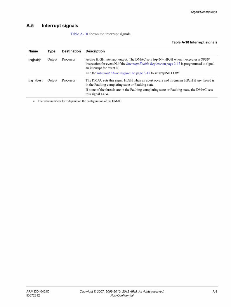
Signal Descriptions
A.5 Interrupt signalsTable A-10 shows the interrupt signals.
Table A-10 Interrupt signals
Name Type Destination Description
irq[x:0]a Output Processor Active HIGH interrupt output. The DMAC sets irq<N> HIGH when it executes a DMASEV instruction for event N, if the Interrupt Enable Register on page 3-13 is programmed to signal an interrupt for event N.Use the Interrupt Clear Register on page 3-15 to set irq<N> LOW.
irq_abort Output Processor The DMAC sets this signal HIGH when an abort occurs and it remains HIGH if any thread is in the Faulting completing state or Faulting state.If none of the threads are in the Faulting completing state or Faulting state, the DMAC sets this signal LOW.
a. The valid numbers for x depend on the configuration of the DMAC.
ARM DDI 0424D Copyright © 2007, 2009-2010, 2012 ARM. All rights reserved. A-8ID072812 Non-Confidential

Signal Descriptions
A.6 Tie-off signalsTable A-11 shows the tie-off signals that all configurations of the DMAC contain.
Table A-12 shows the tie-off signals that control the security state of the interrupt outputs and peripheral request interfaces when the DMAC exits from reset.
Table A-11 DMAC tie-off signals
Name Type Source Description
boot_addr[31:0] Input Tie-off Configures the address location that contains the first instruction the DMAC executes, when it exits from reset.
Note The DMAC only uses this address when boot_from_pc is HIGH.
boot_from_pc Input Tie-off Controls the location in which the DMAC executes its initial instruction, after it exits from reset:0 = DMAC waits for an instruction from either APB interface1 = DMA manager thread executes the instruction that is located at the address that boot_addr[31:0] provides.
boot_manager_ns Input Tie-off When the DMAC exits from reset, this signal controls the security state of the DMA manager thread:0 = assigns DMA manager to the Secure state1 = assigns DMA manager to the Non-secure state.
Table A-12 Interrupt and peripheral tie-off signals
Name Type Source Description
boot_irq_ns[x:0]a Input Tie-off Controls the security state of an event-interrupt resource, when the DMAC exits from reset:boot_irq_ns[x] is LOW
The DMAC assigns event<x> or irq[x] to the Secure state.boot_irq_ns[x] is HIGH
The DMAC assigns event<x> or irq[x] to the Non-secure state.
boot_periph_ns[x:0]a Input Tie-off Controls the security state of a peripheral request interface, when the DMAC exits from reset:boot_periph_ns[x] is LOW
The DMAC assigns peripheral request interface x to the Secure state.boot_periph_ns[x] is HIGH
The DMAC assigns peripheral request interface x to the Non-secure state.
Note Some configurations of the DMAC might not provide these signals because the DMAC does not contain a peripheral request interface. See Peripheral request interface on page A-7.
a. The width of this bus depends on the configuration of the DMAC. See the CoreLink DMA-330 DMA Controller Supplement to AMBA Designer ADR-400 User Guide for information about the bus widths that the DMAC permits.
ARM DDI 0424D Copyright © 2007, 2009-2010, 2012 ARM. All rights reserved. A-9ID072812 Non-Confidential

Appendix B MFIFO Usage Overview
This appendix shows MFIFO usage for some example DMA channel programs. It contains the following sections:• About MFIFO usage overview on page B-2.• Aligned transfers on page B-3.• Unaligned transfers on page B-5.• Fixed transfers on page B-9.
ARM DDI 0424D Copyright © 2007, 2009-2010, 2012 ARM. All rights reserved. B-1ID072812 Non-Confidential
MFIFO Usage Overview
B.1 About MFIFO usage overviewThe MFIFO is a shared resource that is utilized on a first-come, first-served basis by all currently active channels. To a program, it appears as a set of variable-depth parallel FIFOs, one per channel, with the restriction that the total depth of all the FIFOs cannot exceed the configured size of the MFIFO. The width of the AXI master interface sets the MFIFO width and the MFIFO depth is configurable.
The DMAC is capable of realigning data from the source to the destination. For example, the DMAC shifts the data by two byte lanes when it reads a word from address 0x103 and writes to address 0x205. All byte manipulations occur when data enters the MFIFO, as a result of an AXI read because of a DMALD instruction, so that the DMAC is not required to manipulate the data when it removes it from the MFIFO, as a result of an AXI write because of a DMAST instruction. Therefore the storage and packing of the data in the MFIFO is determined by the destination address and transfer characteristics.
When a program specifies that incrementing transactions are to be performed to the destination, the DMAC packs data into the MFIFO to minimize the usage of the MFIFO entries. For example, the DMAC packs two 32-bit words into a single entry in the MFIFO when the DMAC has a 64-bit AXI data bus and the program uses a source address of 0x100, and destination address of 0x200.
In certain situations, the number of entries required to store the data loaded from a source is not a simple calculation of amount of source data divided by MFIFO width. The calculation of the number of entries required is not simple when any of the following occur:• The source address is not aligned to the AXI bus width.• The destination address is not aligned to the AXI bus width.• The transactions are to a fixed destination, that is, a non-incrementing address.
The DMALD and DMAST instructions each specify that an AXI transaction is to be performed. The amount of data transferred by an AXI transaction depends on the values programmed in to the CCRn Register and the address of the transaction. See the AMBA AXI and ACE Protocol Specification for information about unaligned transfers.
The following sections provide several example DMAC programs together with illustrations of the MFIFO usage:• Aligned transfers on page B-3.• Unaligned transfers on page B-5.• Fixed transfers on page B-9.
Note • These sections show MFIFO usage in the following ways:
— A graph of the number of MFIFO entries versus time.— A diagram of the byte-lane manipulation that the DMAC performs when data enters
the MFIFO.
• All the examples use a DMAC configuration with a 64-bit AXI data bus. The numbers 0 and 7 in the MFIFO diagrams indicate the byte lanes in the MFIFO.
ARM DDI 0424D Copyright © 2007, 2009-2010, 2012 ARM. All rights reserved. B-2ID072812 Non-Confidential
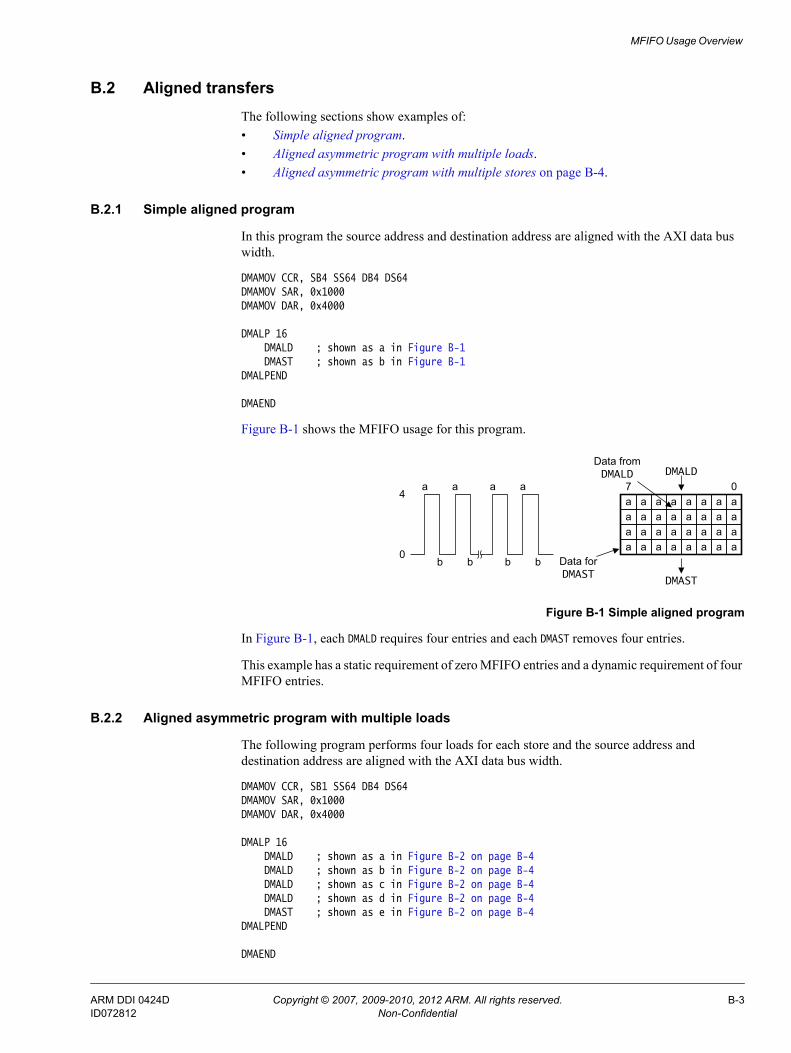
MFIFO Usage Overview
B.2 Aligned transfersThe following sections show examples of:• Simple aligned program.• Aligned asymmetric program with multiple loads.• Aligned asymmetric program with multiple stores on page B-4.
B.2.1 Simple aligned program
In this program the source address and destination address are aligned with the AXI data bus width.
DMAMOV CCR, SB4 SS64 DB4 DS64DMAMOV SAR, 0x1000DMAMOV DAR, 0x4000
DMALP 16DMALD ; shown as a in Figure B-1DMAST ; shown as b in Figure B-1
DMALPEND
DMAEND
Figure B-1 shows the MFIFO usage for this program.
Figure B-1 Simple aligned program
In Figure B-1, each DMALD requires four entries and each DMAST removes four entries.
This example has a static requirement of zero MFIFO entries and a dynamic requirement of four MFIFO entries.
B.2.2 Aligned asymmetric program with multiple loads
The following program performs four loads for each store and the source address and destination address are aligned with the AXI data bus width.
DMAMOV CCR, SB1 SS64 DB4 DS64DMAMOV SAR, 0x1000DMAMOV DAR, 0x4000
DMALP 16DMALD ; shown as a in Figure B-2 on page B-4DMALD ; shown as b in Figure B-2 on page B-4DMALD ; shown as c in Figure B-2 on page B-4DMALD ; shown as d in Figure B-2 on page B-4DMAST ; shown as e in Figure B-2 on page B-4
DMALPEND
DMAEND
0
4a a a a
b b b b
Data from DMALD
a a a a a a a a07
Data for DMAST
DMALD
DMAST
a a a a a a a aa a a a a a a aa a a a a a a a
ARM DDI 0424D Copyright © 2007, 2009-2010, 2012 ARM. All rights reserved. B-3ID072812 Non-Confidential
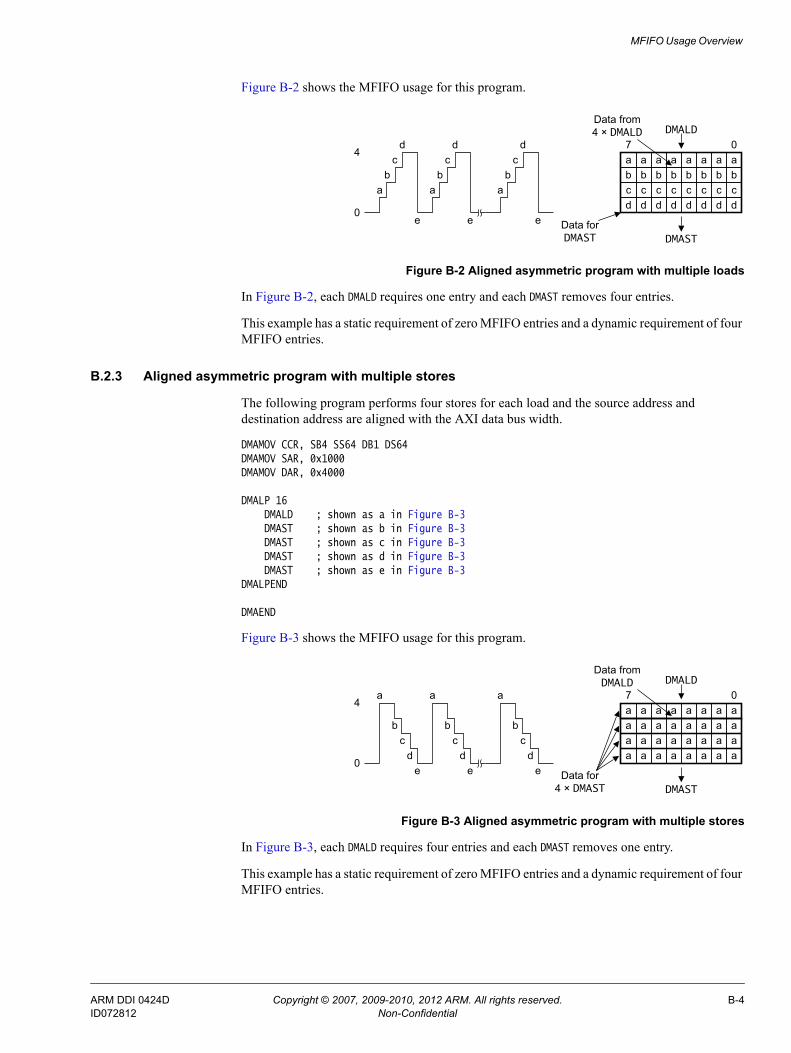
MFIFO Usage Overview
Figure B-2 shows the MFIFO usage for this program.
Figure B-2 Aligned asymmetric program with multiple loads
In Figure B-2, each DMALD requires one entry and each DMAST removes four entries.
This example has a static requirement of zero MFIFO entries and a dynamic requirement of four MFIFO entries.
B.2.3 Aligned asymmetric program with multiple stores
The following program performs four stores for each load and the source address and destination address are aligned with the AXI data bus width.
DMAMOV CCR, SB4 SS64 DB1 DS64DMAMOV SAR, 0x1000DMAMOV DAR, 0x4000
DMALP 16DMALD ; shown as a in Figure B-3DMAST ; shown as b in Figure B-3DMAST ; shown as c in Figure B-3DMAST ; shown as d in Figure B-3DMAST ; shown as e in Figure B-3
DMALPEND
DMAEND
Figure B-3 shows the MFIFO usage for this program.
Figure B-3 Aligned asymmetric program with multiple stores
In Figure B-3, each DMALD requires four entries and each DMAST removes one entry.
This example has a static requirement of zero MFIFO entries and a dynamic requirement of four MFIFO entries.
Data from 4 × DMALD
a a a a a a a a07
Data for DMAST
DMALD
DMAST
b b b b b b b bc c c c c c c cd d d d d d d d
0
4
ab
cd
e
ab
cd
ab
cd
e e
Data from DMALD
a a a a a a a a07
Data for 4 × DMAST
DMALD
DMAST
a a a a a a a aa a a a a a a aa a a a a a a a
0
4
dc
b
a
ed
cb
a
dc
b
a
e e
ARM DDI 0424D Copyright © 2007, 2009-2010, 2012 ARM. All rights reserved. B-4ID072812 Non-Confidential

MFIFO Usage Overview
B.3 Unaligned transfersThe following sections show examples of:• Aligned source address to unaligned destination address.• Unaligned source address to aligned destination address on page B-6.• Unaligned source address to aligned destination address, with excess initial load on
page B-7.• Aligned burst size, unaligned MFIFO on page B-8.
B.3.1 Aligned source address to unaligned destination address
In this program, the source address is aligned with the AXI data bus width but the destination address is unaligned. The destination address is not aligned to the destination burst size so the first DMAST instruction removes less data than the first DMALD instruction reads. Therefore, a final DMAST of a single word is required to clear the data from the MFIFO.
DMAMOV CCR, SB4 SS64 DB4 DS64DMAMOV SAR, 0x1000DMAMOV DAR, 0x4004
DMALP 16DMALD ; shown as a1, ... a, an in Figure B-4DMAST ; shown as b in Figure B-4
DMALPEND
DMAMOV CCR, SB4 SS64 DB1 DS32DMAST ; shown as c in Figure B-4
DMAEND
Figure B-4 shows the MFIFO usage for this program.
Figure B-4 Aligned to unaligned program
The first DMALD instruction loads four doublewords but because the destination address is unaligned, the DMAC shifts them by four bytes and therefore it uses five entries in the MFIFO. Each DMAST requires only four entries of data and therefore the extra entry remains in use for the duration of the program until it is emptied by the last DMAST.
Data from DMALD
a1 a1 a1 a1
07
Data forfirst DMAST
DMALD
DMAST
a1 a1 a1 a1 a1 a1 a1 a1
a1 a1 a1 a1 a1 a1 a1 a1
a1 a1 a1 a1 a1 a1 a1 a1
0
5
1
a1
b
a a an
b b bc a a a a a1 a1 a1 a1
a a a a a a a aa a a a a a a aa a a a a a a a
an an an an
Data for 15 × DMAST
Data for last DMAST
.
.
.
ARM DDI 0424D Copyright © 2007, 2009-2010, 2012 ARM. All rights reserved. B-5ID072812 Non-Confidential
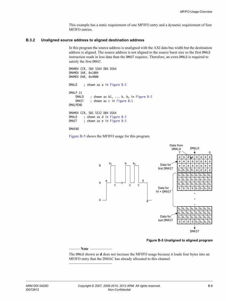
MFIFO Usage Overview
This example has a static requirement of one MFIFO entry and a dynamic requirement of four MFIFO entries.
B.3.2 Unaligned source address to aligned destination address
In this program the source address is unaligned with the AXI data bus width but the destination address is aligned. The source address is not aligned to the source burst size so the first DMALD instruction reads in less data than the DMAST requires. Therefore, an extra DMALD is required to satisfy the first DMAST.
DMAMOV CCR, SB4 SS64 DB4 DS64DMAMOV SAR, 0x1004DMAMOV DAR, 0x4000
DMALD ; shown as a in Figure B-5
DMALP 15DMALD ; shown as b1, ... b, bn in Figure B-5DMAST ; shown as c in Figure B-5
DMALPEND
DMAMOV CCR, SB1 SS32 DB4 DS64DMALD ; shown as d in Figure B-5DMAST ; shown as e in Figure B-5
DMAEND
Figure B-5 shows the MFIFO usage for this program.
Figure B-5 Unaligned to aligned program
Note The DMALD shown as d does not increase the MFIFO usage because it loads four bytes into an MFIFO entry that the DMAC has already allocated to this channel.
0
4a
b1
c
b bn
c cd
e
8
Data from DMALD
a a a a a a a a07
Data forfirst DMAST
DMALD
DMAST
a a a a a a a aa a a a a a a ab1 b1 b1 b1 a a a a
b1 b1 b1 b1 b1 b1 b1 b1
b1 b1 b1 b1 b1 b1 b1 b1
b1 b1 b1 b1 b1 b1 b1 b1
b b b b b1 b1 b1 b1Data for 14 × DMAST .
.
.bn bn bn bn bn bn bnbn
bn bn bn bn bn bn bn bn
bn bn bn bn bn bn bn bn
d d d d bn bn bn bn
Data forlast DMAST
ARM DDI 0424D Copyright © 2007, 2009-2010, 2012 ARM. All rights reserved. B-6ID072812 Non-Confidential

MFIFO Usage Overview
The first DMALD instruction does not load sufficient data to enable the DMAC to execute a DMAST and therefore the program includes an additional DMALD, prior to the start of the loop. After the first DMALD, the subsequent DMALDs align with the source burst size. This optimizes the performance but it requires a larger number of MFIFO entries.
This example has a static requirement of four MFIFO entries and a dynamic requirement of four MFIFO entries.
B.3.3 Unaligned source address to aligned destination address, with excess initial load
This program is an alternative to that described in Unaligned source address to aligned destination address on page B-6. The program uses a different sequence of source bursts that might be less efficient but requires fewer MFIFO entries.
DMAMOV CCR, SB5 SS64 DB4 DS64DMAMOV SAR, 0x1004DMAMOV DAR, 0x4000DMALD ; shown as a in Figure B-6DMAST ; shown as b in Figure B-6
DMAMOV CCR, SB4 SS64 DB4 DS64DMALP 14
DMALD ; shown as c and cn in Figure B-6DMAST ; shown as d in Figure B-6
DMALPEND
DMAMOV CCR, SB3 SS64 DB4 DS64DMALD ; shown as e in Figure B-6
DMAMOV CCR, SB1 SS32 DB4 DS64DMALD ; shown as f in Figure B-6DMAST ; shown as g in Figure B-6
DMAEND
Figure B-6 shows the MFIFO usage for this program.
Figure B-6 Unaligned to aligned with excess initial load
0
5
1
a
b
c c cn
d
e
d d
f
g
4
Data from DMALD
a a a a a a a a
07
Data forfirst DMAST
DMALD
DMAST
a a a a a a a aa a a a a a a a
c c c a a a ac c c c c c c cc c c c c c c cc c c c c c c c
e e e e cn cn cn cn
Data for 14 × DMAST .
.
.
e e e e e e e ee e e e e e e ef f f f e e e e
Data forlast DMAST
a a a a a a a a
c
ARM DDI 0424D Copyright © 2007, 2009-2010, 2012 ARM. All rights reserved. B-7ID072812 Non-Confidential

MFIFO Usage Overview
Note The DMALD shown as f does not increase the MFIFO usage because it loads four bytes into an MFIFO entry that the DMAC has already allocated to this channel.
The first DMALD instruction loads five beats of data to enable the DMAC to execute the first DMAST. After the first DMALD, the subsequent DMALDs are not aligned to the source burst size, for example the second DMALD reads from address 0x1028. After the loop, the final two DMALDs read the data required to satisfy the final DMAST.
This example has a static requirement of one MFIFO entry and a dynamic requirement of four MFIFO entries.
B.3.4 Aligned burst size, unaligned MFIFO
In this program the destination address, which is narrower than the MFIFO width, aligns with the burst size but does not align with the MFIFO width.
DMAMOV CCR, SB4 SS32 DB4 DS32DMAMOV SAR, 0x1000DMAMOV DAR, 0x4004
DMALP 16DMALD ; shown as a in Figure B-7DMAST ; shown as b in Figure B-7
DMALPEND
DMAEND
Figure B-7 shows the MFIFO usage for this program.
Figure B-7 Aligned burst with unaligned MFIFO width
If the DMAC configuration has a 32-bit AXI data bus width then this program requires four MFIFO entries. However, in this example the DMAC has a 64-bit AXI data bus width and, because the destination address is not 64-bit aligned, it requires three rather than the expected two MFIFO entries.
This example has a static requirement of zero MFIFO entries and a dynamic requirement of three MFIFO entries.
0
3a a a a
b b b b
Data from DMALD
a a a a07
Data for DMAST
DMALD
DMAST
a a a a a a a aa a a a
ARM DDI 0424D Copyright © 2007, 2009-2010, 2012 ARM. All rights reserved. B-8ID072812 Non-Confidential

MFIFO Usage Overview
B.4 Fixed transfersThe following section shows an example of a:• Fixed destination with aligned address.
B.4.1 Fixed destination with aligned address
In this program the source address and destination address are aligned with the AXI data bus width, and the destination address is fixed.
DMAMOV CCR, SB2 SS64 DB4 DS32 DAFDMAMOV SAR, 0x1000DMAMOV DAR, 0x4000
DMALP 16DMALD ; shown as a in Figure B-8DMAST ; shown as b in Figure B-8
DMALPEND
DMAEND
Figure B-8 shows the MFIFO usage for this program.
Figure B-8 Fixed destination with aligned address
Each DMALD in the program loads two 64-bit data transfers into the MFIFO. Because the destination address is a 32-bit fixed address then the DMAC splits each 64-bit data item across two entries in the MFIFO.
This example has a static requirement of zero MFIFO entries and a dynamic requirement of four MFIFO entries.
0
4a a a a
b b b b
Data from DMALD
a a a a07
Data for DMAST
DMALD
DMAST
a a a aa a a aa a a a
ARM DDI 0424D Copyright © 2007, 2009-2010, 2012 ARM. All rights reserved. B-9ID072812 Non-Confidential

Appendix C Revisions
This appendix describes the technical changes between released issues of this book.
Table C-1 Differences between issue A and issue B
Change Location Affects
Changed product designator from PL330 to DMA-330 Throughout book r1p0
Updated description about how a DMA manager thread can move from the Stopped state to the Executing state
Stopped on page 2-9 All revisions
Updated description about how a thread can move from the Executing state to the:• At barrier state.• Faulting completing state.• Faulting state.
Executing on page 2-9 All revisions
Updated description about which instruction moves the thread to the Stopped state
Faulting on page 2-10 All revisions
Added information about boot_manager_ns when the DMAC enters the Stopped state
How to set the location of the first instruction for the DMAC to execute on page 2-11
All revisions
Added subsection about peripheral acceptance request capability
Request acceptance capability configuration on page 2-16
All revisions
Updated description and added example program code • Peripheral length management on page 2-17.• DMAC length management on page 2-19.
All revisions
ARM DDI 0424D Copyright © 2007, 2009-2010, 2012 ARM. All rights reserved. C-1ID072812 Non-Confidential

Revisions
Updated description and added additional examples of how to use events and interrupts
Using events and interrupts on page 2-23 All revisions
Added the store before load abort Abort sources on page 2-25 r1p0
Updated the conditions that can cause a precise abort or an imprecise abort
All revisions
Added the precise lockup detection abort Watchdog abort on page 2-26 r1p0
Updated description for DMASEV Security usage on page 2-29 All revisions
Added information about dst_burst_len×dst_burst_size ≥ endian_swap_size
Endian swap size restrictions on page 2-35 All revisions
Updated information about data discontinuity Updating DMA channel control registers during a DMA cycle on page 2-36
All revisions
Updated information about programming restrictions for the MFIFO
Resource sharing between DMA channels on page 2-37 All revisions
Updated the RTL register names • DMA Manager Status Register on page 3-11.• Event-Interrupt Raw Status Register on page 3-13.• Interrupt Status Register on page 3-14.• Fault Status DMA Manager Register on page 3-16.• Fault Status DMA Channel Register on page 3-16.• Fault Type DMA Manager Register on page 3-17.• Fault Type DMA Channel Registers on page 3-18.• Channel Status Registers on page 3-21.• Source Address Registers on page 3-23.• Destination Address Registers on page 3-24.• Channel Control Registers on page 3-25• DMA Configuration Register on page 3-38
All revisions
Updated the description of the instr_fetch_err bit • Table 3-15 on page 3-18.• Table 3-16 on page 3-19.
All revisions
Added the st_data_unavailable bit Fault Type DMA Channel Registers on page 3-18 r1p0
Added information about precise and imprecise aborts Fault Type DMA Channel Registers on page 3-18 All revisions
Updated the description of the Channel status field when the value is 0b0110
Channel Status Registers on page 3-21 All revisions
Updated the description and the valid states of the dst_burst_size field and src_burst_size field
Channel Control Registers on page 3-25 All revisions
Updated the description of the bit numbers for the src_prot_ctrl field
Channel Control Registers on page 3-25 All revisions
Updated the description of the INS field Configuration Register 3 on page 3-36 All revisions
Added the WD Register Watchdog Register on page 3-40 r1p0
Updated the options of the revision field Peripheral Identification Register 2 on page 3-42 All revisions
Updated addition description DMAADDH on page 4-4 All revisions
Removed description for suspended channels DMAEND on page 4-5 r1p0
Table C-1 Differences between issue A and issue B (continued)
Change Location Affects
ARM DDI 0424D Copyright © 2007, 2009-2010, 2012 ARM. All rights reserved. C-2ID072812 Non-Confidential

Revisions
Updated the functionality when a DMA channel is not in the Stopped state
DMAGO on page 4-6 All revisions
Updated the description of the S and B parameters DMALD[S|B] on page 4-8 All revisions
Updated the description of the S parameter DMALDP<S|B> on page 4-9 All revisions
Updated the description of the instruction DMALPEND[S|B] on page 4-11 All revisions
Updated the description of the S and B parameters DMAST[S|B] on page 4-15 All revisions
Updated the description of the invalid parameter DMAWFE on page 4-18 All revisions
Updated the instruction syntax DMAWFP on page 4-18 All revisions
Removed DMALPEND instruction Assembler directives on page 4-21 All revisions
Updated the description and options for the SS and DS parameters
DMAMOV CCR on page 4-22 All revisions
Added example MFIFO usage description Appendix B MFIFO Usage Overview All revisions
Table C-2 Differences between issue B and issue C
Change Location Affects
Description of wrapping address bursts Figure 2-3 on page 2-5 in AXI master interface on page 2-4
All revisions
Updated the description of restrictions when using the endian swap feature
Endian swap size restrictions on page 2-35 All revisions
Additional sections for:• AXI data transfer size on page 2-33.• AXI bursts crossing 4Kbyte boundaries on page 2-33.• AXI burst types on page 2-33.
Constraints and limitations of use on page 2-33 All revisions
Change to the Bit [N] = 1 description for the INT_EVENT_RIS Register bit assignments
Table 3-10 on page 3-14 All revisions
Added the Add Negative Halfword instruction, DMAADNH Instructions on page 4-4 r1p0
Added awcache and arcache signals • Table A-2 on page A-3.• Table A-5 on page A-4.
All revisions
Added AXI write addresses section AXI write addresses on page 2-33 All revisions
Added AXI write data interleaving section AXI write data interleaving on page 2-34 All revisions
Made changes to the description of how to use the drlast signal • Peripheral request interface on page 2-15.• Request acceptance capability configuration
on page 2-16.
All revisions
Table C-1 Differences between issue A and issue B (continued)
Change Location Affects
ARM DDI 0424D Copyright © 2007, 2009-2010, 2012 ARM. All rights reserved. C-3ID072812 Non-Confidential

Revisions
Table C-3 Differences between issue C and issue D
Change Location Affects
Updated the information about boot_manager_ns How to set the location of the first instruction for the DMAC to execute on page 2-11
All revisions
Updated the reset value of the CCRn registers Table 3-3 on page 3-7 All revisions
ARM DDI 0424D Copyright © 2007, 2009-2010, 2012 ARM. All rights reserved. C-4ID072812 Non-Confidential