
CORE SPECIFICATION - Fort Vale Engineering · PDF fileCORE SPECIFICATION GAS TANK CONTAINER //...
30
CORE SPECIFICATION // ISO Liquefied Gas Tank Container Equipment © Fort Vale Engineering Ltd. 2009 REV01_10.12.07
Transcript of CORE SPECIFICATION - Fort Vale Engineering · PDF fileCORE SPECIFICATION GAS TANK CONTAINER //...

CORE SPECIFICATION//
ISO Liquefied GasTank ContainerEquipment
© Fort Vale Engineering Ltd. 2009
REV01_10.12.07

PRESSURE RELIEF EQUIPMENT //
» 80MM INTERNAL GAS RELIEF VALVES» 80MM INTERNAL GAS RELIEF VALVE & BURSTING DISC HOLDER
INTERNAL EMERGENCY VALVES //
» 2” GAS SHORT PROFILE COMPOSITE FOOTVALVE ASSEMBLY» 2” LIQUID PHASE EXCESS FLOW GAS FOOTVALVE» EXCESS FLOW EMERGENCY VALVE OPERATION
BALL VALVE //
» 2” FULL BORE GAS BALL VALVE
ACME OUTLET ASSEMBLIES //
» ACME OUTLET ASSEMBLIES
AFTER SALES //
» MAINTENANCE» WORLDWIDE DISTRIBUTORS
CONTENTS//
CORESPECIFICATIONGAS TANK CONTAINER//
© Fort Vale Engineering Ltd. 2009

PRESSURERELIEF EQUIPMENT//
© Fort Vale Engineering Ltd. 2009 Page 1

PRESSURE RELIEF EQUIPMENT//
The is available in three basic designs:
! Pressure relief valve only - the most basic model.
! Pressure relief valve with bursting disc holder - for tanks carrying products that require a burst disc to be fitted in series.
! Pressure relief valve only with bursting disc provision - the mounting flange allows the fitting of a burst disc holder at a later stage.
The valve is located on the top of the tank in the gas phase and is designed to relieve any accidental over-pressure, including a fire engulfment situation.
The Fort Vale design incorporates a number of unique features:-
! The main seal can be replaced in-situ without taking the valve off the tank, even with a pressurized tank.
! The valve can be serviced without the need for special equipment.
! The valve will operate manually even if its port is covered in ice due to harsh weather conditions.
80mm gas relief valve
© Fort Vale Engineering Ltd. 2009 Page 2

Range
Associated Parts
Fitting Details
Specification
GAS035 REV03-23.04.14
Weight 11.7 KgsDesign Temperature -55°C to 80°C (-67°F to 176°F)
Design approval by Lloyds Register of Shipping and Russian Maritime Register of Shipping.
Test certificates supplied as standard. Please see separate data sheets for details on flow rates.
Tests may be witnessed and valves individually stamped by an independent inspectorate by arrangement.
MKII 80mm Internal Gas Relief Valve
Options
- Suitable for a pressure range of between 100 - 505 PSI (6.90 - 34.82 bar). Contact parts manufactured in 304/316 stainless steel. Fitted with PTFE seals as standard. Suitable for a burst disc to be fitted.
- Kalrez® seal optional.
Example shown : 016/2XXX6
Associated Parts Part No.
CNAF/PTFE gasket 5005-826
NOTE: for use in conjunction with the Fort Vale standard burst disc holder.
Part No. Description
016/2XXX6 80mm Internal gas relief valve, 184.2mm PCD flange drilling
© Fort Vale Engineering Ltd. 2014
DataMKII 80mm Internal Gas Relief
Valve (Cutaway flange)
®
Ø 105.9
Ø 157.0
Ø 151.08
Ø 141.22
63.1
33.0
247.6
8 HOLES 18.0 EQUI-SPACED ON A 184.2 PCD
Page 3

© Fort Vale Engineering Ltd. 2013
Parts drawing
GAS036 REV02-23.09.13
SEAL KITPart number 006/00SK contains all parts marked
Part number 016/00RK contains all parts markedREPAIR KIT
A detailed step-by-step repair manual is available for our 80mm Gas Relief Valves. Please contact our Sales team for further information.
SELF ADHESIVE DECALPart No. 005/DECALText in English, German & French
Springs and Spring Locators
Please note that the top and bottom spring locators are manufactured to suit the dimensions of the spring pair. We advise that you contact our Sales department for spring information.
Item Description Part No.
1 M20 x 1.5mm lock nut 5112-036 2 Cowl retaining washer 055/0135 3 Cowl 055/0130 4 M20 x 1.5mm full nut 5112-033 5 M20 spring washer 5113-016 6 Poppet head 055/0127 7 Main seal 5005-825 8 Neoprene O ring 5005-995 9 Poppet stem assembly 055/0120 10 Body weld assembly (016/2XXX6) 055/0200 11 Spindle guide bush 055/0115 12 Stop collar 055/0125 13 Retaining ring clip 055/0114 14 PTFE gasket 5005-826 15 Top spring locator (see below) 055/0116X 16 Spring pair (see below) 8104-XXXX 17 Bottom spring locator (see below) 055/0110X 18 M6 x 8mm grubscrew 5111-133 19 Spring nut 055/0020 20 Retaining wire & ferrule 055/0060
DataMKII 80mm Internal Gas Relief
Valve (Cutaway flange)
®
1
2
3
4
5
6
7
9
8
10
11
12
13
14
15
16
17
18
19
20
Page 4

Part No. Dimension A Dimension B Flange drilling pattern
015/2XXX5 Ø 183.9 Ø 266.7 8 holes Ø 26.0mm equi-spaced on a 220.0mm PCD 015/2XXX0 Ø 202.9 Ø 301.0 8 holes Ø 26.0mm equi-spaced on a 250.0mm PCD
Range
Associated Parts
Specification
GAS030 REV01-24.09.13
MKII 80mm Internal Gas Relief Valve & Bursting Disc Holder
Options
- Suitable for a pressure 505 PSI (6.90 - 34.82 bar). Contact parts manufactured in 304/316 stainless steel. Fitted with PTFE seals as standard.
- available with ¼” BSP or ¼” NPT horizontal or vertical pressure gauge fitting. Alternative flange drillings are available on request. Please see below for standard drilling patterns. Kalrez
range of between 100 -
® seal optional. Oxygen service cleaning available.
Weight 31.5 Kgs *See NoteDesign Temperature -55°C to 80°C (-67°F to 176°F)
Note : Weight varies according to valve specification
Design approval by Lloyds Register of Shipping and Russian Maritime Register of Shipping.
Test certificates supplied as standard. Please see separate data sheets for details on flow rates.
Tests may be witnessed and valves individually stamped by an independent inspectorate by arrangement.
Example shown : 015/2XXX5
Fitting Details
DataMKII 80mm Internal Gas Relief
Valve & Bursting Disc Holder
®
© Fort Vale Engineering Ltd. 2013
Part No. Description
015/2XXX5 Valve with flange drilled 220mm PCD 015/2XXXXA Valve with 90° ¼” BSP check port 015/2XXXXB Valve with 90° ¼” NPT check port 015/2XXXXC Valve with ¼” BSP vertical gauge port 015/2XXX0 Valve with flange drilled 250mm PCD
Associated Parts Part No.
Pressure Gauges to suit various valve pressures
Various – please contact our Sales team
CNAF/PTFE gasket (015/2XXX0) 5005-815 PTFE gasket (015/2XXX5) 5005-812 Emergency blank cap – 2 hole 005/0060X Emergency blank cap – 4 hole 015/0070X
Ø 89.9
Ø 105.9
Ø 157.2
DIMENSION A
DIMENSION B
39.1
99.1
204.7
Page 5

GAS031 REV02-24.09.13
SEAL KITPart number 005/00SK contains all parts marked
Part number 015/00RK contains all parts markedREPAIR KIT
A detailed step-by-step repair manual is available for our 80mm Gas Relief Valves. Please contact our Sales team for further information.
SELF ADHESIVE DECALPart No. 005/DECALText in English, German & French
Parts drawing
Springs and Spring Locators
Please note that the top and bottom spring locators are manufactured to suit the dimensions of the spring pair. We advise that you contact our Sales department for spring information.
© Fort Vale Engineering Ltd. 2013
DataMKII 80mm Internal Gas Relief
Valve & Bursting Disc Holder
®
Item Description Part No.
1 M20 x 1.5mm lock nut 5112-036 2 Cowl retaining washer 055/0135 3 Cowl 055/0130 4 M20 x 1.5mm full nut 5112-033 5 M20 spring washer 5113-016 6 Poppet head 055/0127 7 Main seal 5005-825 8 Neoprene O ring 5005-995 9 Poppet stem assembly 055/0120 10 M16 full nut (8) 5112-003 11 M16 spring washer (8) 5113-012 12 Body weld assembly 055/0200 13 Top spring locator (see below) 055/0116X 14 Spindle guide bush 055/0115 15 Stop collar 055/0125 16 Retaining ring clip 055/0114 17 Spring pair (see below) 8104-XXXX 18 Bottom spring locator (see below) 055/0110X 19 Spring retainer 055/0020 20 M16 stud (8) 055/0055 21 Tamper wire 055/0060 22 Stainless ferrule SF2.5 23 M6 x 8mm grubscrew 5111-133 24 PTFE gasket 5005-826 25 Burst disc holder (015/2XXX5)
(015/2XXX0) 055/0190 055/0290
26 11mm ball 055/0031 27 ¼” BSP taper plug 5128-009 28 Ball seal 055/0030 29 Spring 5104-115 30 PTFE tank seal (sold separately) 5005-XXX 31 Burst disc (sold separately) Various 32 Bursting disc support flange 044/1034 33 8mm Belleville washer (40) 5113-020 34 Anti rotation tab (5) 055/0025 35 Hex bolt (10) 5111-011
1
2
3
4
5
6
7
8
9
11
12
13
14
15
17
18
19
23
24
25
26
27
28
29
30
31
32
33
35
34
10
16
20
21
22
Page 6
© Fort Vale Engineering Ltd. 2013
Range
Associated Parts
Specification
Fitting Details
GAS032 REV02-24.09.13
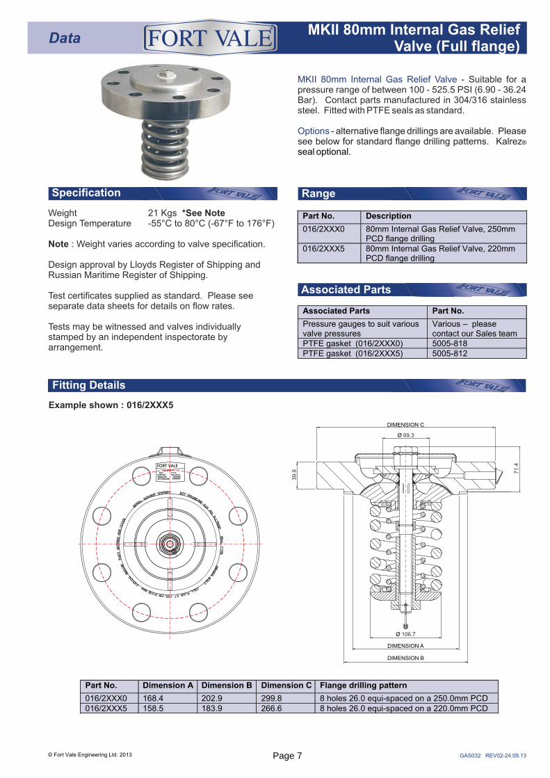
MKII 80mm Internal Gas Relief Valve
Options
- Suitable for a pressure range of between 100 - 525.5 PSI (6.90 - 36.24 Bar). Contact parts manufactured in 304/316 stainless steel. Fitted with PTFE seals as standard.
- alternative flange drillings are available. Please see below for standard flange drilling patterns. Kalrez®
seal optional.
Weight 21 Kgs *See NoteDesign Temperature -55°C to 80°C (-67°F to 176°F)
Note : Weight varies according to valve specification.
Design approval by Lloyds Register of Shipping and Russian Maritime Register of Shipping.
Test certificates supplied as standard. Please see separate data sheets for details on flow rates.
Tests may be witnessed and valves individually stamped by an independent inspectorate by arrangement.
Example shown : 016/2XXX5
Part No. Description
016/2XXX0 80mm Internal Gas Relief Valve, 250mm PCD flange drilling
016/2XXX5 80mm Internal Gas Relief Valve, 220mm PCD flange drilling
Associated Parts Part No.
Pressure gauges to suit various valve pressures
Various – please contact our Sales team
PTFE gasket (016/2XXX0) 5005-818 PTFE gasket (016/2XXX5) 5005-812
DataMKII 80mm Internal Gas Relief
Valve (Full flange)
®
Part No. Dimension A Dimension B Dimension C Flange drilling pattern
016/2XXX0 168.4 202.9 299.8 8 holes 26.0 equi-spaced on a 250.0mm PCD 016/2XXX5 158.5 183.9 266.6 8 holes 26.0 equi-spaced on a 220.0mm PCD
Ø 69.3
71.4
Ø 106.7
DIMENSION B
DIMENSION A
DIMENSION C
39.9
#######006/2XXX5
316 ST ST SEAL: P.T.F.EPART NO:SERIAL NO:SET PRESSURE
FORT VALE
#######
Page 7

Parts drawing
GAS033 REV02-24.09.13
SEAL KITPart number 006/00SK contains all parts marked
Part number 016/00RK contains all parts markedREPAIR KIT
A detailed step-by-step repair manual is available for our 80mm Gas Relief Valves. Please contact our Sales team for further information.
SELF ADHESIVE DECALPart No. 005/DECALText in English, German & French
Springs and Spring Locators
Please note that the top and bottom spring locators are manufactured to suit the dimensions of the spring pair. We advise that you contact our Sales department for spring information.
© Fort Vale Engineering Ltd. 2013
DataMKII 80mm Internal Gas Relief
Valve (Full flange)
®
Item Description Part No.
1 M20 x 1.5mm lock nut 5112-036 2 Cowl retaining washer 055/0135 3 Cowl 055/0130 4 M20 x 1.5mm full nut 5112-033 5 M20 spring washer 5113-016 6 Poppet head 055/0127 7 Main seal 5005-825 8 Neoprene O ring 5005-995 9 Poppet stem assembly 055/0120X 10 Body weld assembly (016/2XXX5)
(016/2XXX0) 055/0250 055/0260
11 Spindle guide bush 055/0115 12 Stop collar 055/0125 13 Retaining ring clip 055/0114 14 PTFE gasket (supplied separate) 5005-XXX 15 Top spring locator (see below) 055/0116X 16 Spring pair (see below) 8104-XXXX 17 Bottom spring locator (see below) 055/0110X 18 Spring nut 055/0020 19 M6 x 8mm grubscrew 5111-133 20 Tamper wire & ferrule 055/0060
1
2
3
4
5
6
7
8
9
10
11
12
13
14
15
16
17
18
19
20
Page 8

INTERNALEMERGENCYVALVES//
© Fort Vale Engineering Ltd. 2009 Page 9

INTERNAL EMERGENCY VALVES//
Fort Vale offers a range of
for the liquid and gas phases of tank containers.
The 51° valves are designed to fit to the side of the tank whilst the straight valves will fit to the rear of the tank.
The valves operate on the pilot / main closure principle so that they can easily be operated by hand. The half way position of the handle gives a quick pressure balance between the tank and unloading line for a quick set up.
To meet the requirements of IMDG and CFR codes, the valve has an excess flow facility. The main poppet of the valve will close automatically if a rupture of the loading line occurs.
The same valves are fitted to the liquid and gas phase to optimize costs and logistics.
internal emergency valves
1
2
3
4
5
6
© Fort Vale Engineering Ltd. 2009 Page 10

Fitting Details
GAS017 REV01-08.10.07
2” Short Profile Footvalve for compressed liquefied gas
Options a
-500 PSI (34.5 Bar) pressure setting. Inlet flange drilled 4x 18mm holes equi-spaced on a 125mm PCD. DIN 50 PN40. Complete with 2” ball valve. Left hand operation.Contact parts manufactured in 316 stainless steel.Supplied with a 3.25”ACME outlet and cap.
- vailable with a 1.75”ACME outlet. Right handoperation. Also available with a flanged outlet.
Example shown : 802B/0010L
RangeSpecification
Weight 17 KgsDesign Pressure (MAWP) 34.5 Bar (500 PSI)Hydraulic Test Pressure 70 Bar (1015 PSI)Design Temperature Range -55°C to 80°C
(-67°F to 176°F)
Design approval by Lloyds Register of Shipping andRussian Maritime Register of Shipping.All valves may be manufactured to TPED.
Please Note : Tension spring must be fitted to ensurevalve closure in an emergency situation.
Part No. Description
802B/0010R 2” Vapour Phase Footvalve. 1.75” ACMEoutlet, right hand operation
802B/0010L 2” Liquid Phase Footvalve, 3.25” ACMEoutlet, left hand operation
Data
TM
2” Short Profile CompositeFootvalve Assembly
A detailed step-by-step maintenance manual isavailable for our gas footvalves. Please contact ourSales team for further information.
© Fort Vale Engineering Ltd. 2008
4 HOLES Ø 18 EQUI-SPACEDON A 125.0 (4.92”) PCD(DIN50 PN40)
45°
106.6 (4.19”)
Ø60.3
(2.3
8”)
Ø87.1
(3.4
3”)
3.1 (0.12”)
23.1 (0.91”)
96.3 (3.79”)
92.5 (3.64”)
121.2 (4.77”)
Ø165.1
(6.5
0”)Ø
50.0
(1.9
7”)
21.3(0.84”)
233.6 (9.20”)
157.9 (6.22”)
Ø50.8
(2.0
0”)
34.8 (1.37”)99.8
(3.93”)
20.0(0.79”)
70°
10.2 (0.40”)VALVE LIFT
VALVE SHOWN IN OPEN POSITION
223.8 ( 8.81”)
Page 11

Parts drawing
GAS018 REV03-14.07.09
SEAL KITPart no. 252/50SKB contains all parts marked
Part no. 370/33SKB contains all parts marked
REPAIR KITPart no. 252/50RKB contains all parts marked
Part no. 370/33RKB contains all parts marked
DataTM
2” Short Profile Composite Footvalve Assembly
Item Description Part No.
1 M10 self locking nut 5112-008 2 M10 washer 5113-009 3 Handle 370/3306 4 Disc spring (3) 5113-038 5 M6 hex head bolt (4) 5111-022 6 M6 spring washer (7) 5113-008 7 Clamp plate 370/3305B 8 Neoprene O ring 5005-216 9 Neoprene O ring 5005-866N 10 Spindle bush 370/3307B 11 Spindle seal 359/2007 12 PTFE ball seal (2) 370/3302 13 2” Footvalve body 252/5065X 14 Fluorosint bearing pad 252/0580 15 Push stem 252/0525 16 Poppet spring 5104-826 17 Bottom spring pad 252/0526 18 Spider stem guide 252/3165 19 Spindle guide bush 252/0589 20 Poppet head 252/0586 21 M5 castle nut 5112-020 22 Pilot seal retainer 252/0579 23 Pilot seal 252/0583 24 PTFE main seal 252/0563 25 Seal clamp 252/0588 26 M5 sockethead capscrew (3) 5111-118 27 Liquid phase spring 5104-824L Gas phase spring 5104-821G 28 Spring location washer 252/0511 29 Push stem guide bush 252/0565 30 Bottom guide bush 252/0506B 31 Spindle 252/0504 32 Bottom stem seal 359/4007 33 Spacer ring 359/4012
Item Description Part No.
34 Spacer ring 252/0512 35 Top gland seal 359/4013 36 Top seal bush 252/0507 37 Top guide bush 252/0502B 38 M6 hex head bolt (3) 5111-022 39 M6 countersunk screw 5111-018 40 Retaining washer 20370 41 Handle weld assembly 252/3520 42 Stuffing plate 252/5058B 43 Neoprene O ring 5005-216 44 Split bearing 252/0517 45 Neoprene O ring 5005-217 46 Operating cam 252/0527 47 M10 washer 5113-009 48 Split pin (2) 5118-011 49 M12 stud (4) 370/3314 50 50mm ball 370/3301 51 Body seal 370/3303 52 M16 full nut (4) 5112-003 53 M16 spring washer (4) 5113-012 54 M12 spring washer (4) 5113-010 55 M12 full nut (4) 5112-006 56 2” gas ball valve body 370/3368 57 CNAF/PTFE envelope gasket 5005-726 58 3.25” ACME outlet 252/2069 1.75” ACME outlet 252/2084 59 PTFE seal (3.25” ACME) 5005-877 PTFE seal (1.75” ACME) 5005-878 60 3.25” ACME cap plug 252/2076 1.75” ACME cap plug 252/2086 61 3.25” ACME dust cap 252/2075 1.75” ACME dust cap 252/2085 62 Retaining ring clip (3.25” ACME) 5120-027 Retaining ring clip (1.75” ACME) 5120-028 63 M16 hex head bolt (4) 5111-090 64 Spindle 370/3320 65 Bottom bush 370/3321
© Fort Vale Engineering Ltd. 2009
Above view shows liquid phase valve
1
2
3
4
5
6
7
8
9
64
65
12
10
11
13
14
15
1617
18
1920
21
22
48
2324
2526
2728
29
30
31
34
35
36
37
43
44
45
38
39
40
41
42
6
46
47
4849
50
12
5152
5354
5556
57
58
59
60
61
62
63
33
32
Page 12

Data2” Liquid Phase Excess
Flow Gas FootvalveTM
Fitting Details
RangeSpecification
GAS019 REV01-03.12.07
Example shown : 252/3750B
2” Liquid Phase Excess Flow Gas Footvalve
Options
- with 70°actuator. 500 PSI (34.5 Bar) pressure rating. Inlet flangedrilled 8 x 18mm holes on a 127mm PCD. 2” ASA 300lbs.Contact parts manufactured in 316 stainless steel.
- gas phase footvalve available.
Part No. Description
252/3750B 2” Liquid phase excess flow gas footvalvewith 70° actuator
252/3760B 2” Vapour phase excess flow gasfootvalve with 70° actuator
Weight 9 KgsDesign Pressure 34.5 Bar (500 PSI)Service Test Pressure 61 Bar (884.5 PSI)Design Temperature Range -55°C to 80°C
(-67°F to 176°F)
Design approval by Lloyds Register of Shipping andRussian Maritime Register of Shipping
All valves may be manufactured to TPED.
© Fort Vale Engineering Ltd. 2008
106.3
(4.1
8”)
6.0
(0.2
4”)
8 HOLES 18.0MM EQUISPACED ON A 127MMPCD
Ø60.2 (2.37”)
65.7
(2.5
9”)
113.3 (4.46”)
22.5°8 HOLES Ø18.0MM EQUISPACED ON A 127MMPCD
70°
VALVE SHOWN INOPEN POSITION
10.0
(0.4
0”)
Ø165.1 (6.50”)
Ø87.0 (3.43”)
152.2(5.99”)
4.2
(0.1
7”)
51°
24
.6(0
.97”)
22.1(0.87”)
1.5(0.06”)
Ø52
.5(2
.07”
)
Ø92
.6(3
.65”
)
Ø16
5.1
(6.5
0”)
7.6 (0.30”)
14.7 (0.58”)
20.1 (0.79”)
99.8 (3.93”)
102.
3(4
.03”
)
Page 13

Parts drawing
Data2” Liquid Phase Excess
Flow Gas FootvalveTM
GAS020 REV01-04.12.07
SEAL KITPart number contains all parts marked252/50SKB
REPAIR KITPart number contains all parts marked252/50RKB
A detailed step-by-step maintenance manual is availablefor our gas footvalves in both printed and CD formats.Please contact our Sales team for further information.
Please Note : Tension spring must be fitted to ensurevalve closure in an emergency situation.
Item Description Part No.
1 2” gas valve body 252/3755A
2 Split pin (2) 5118-011
3 M10 washer 5113-009
4 Operating cam 252/0527
5 Bottom guide bush 252/0506
6 Spindle 252/0504
7 Bottom stem seal 359/4007
8 Spacer ring 359/4012
9 Spacer ring 252/0512
10 Top gland seal 359/4013
11 Top seal bush 252/0507
12 Top guide bush (B series valve) 252/0502B
13 Stuffing plate 252/5058B
14 M6 spring washer (3) 5113-008
15 M6 hex head bolt (3) 5111-022
16 Handle 252/3520
17 Retaining washer 20370
Item Description Part No.
18 M6 countersunk bolt 5111-018
19 Neoprene O ring 5005-216
20 Split bearing 252/0517
21 Neoprene O ring 5005-217
22 Fluorosint bearing pad 252/0580
23 Push stem 252/0525
24 Poppet spring 5104-826
25 Bottom spring pad 252/0526
26 Push stem guide bush 252/0565
27 Body top gasket 5005-571
28 Snap ring 5120-036
29 Inlet tube 252/0535
30 Spring location washer 252/0511
31 Pilot spring (part no varies) 5104-XXXX
32 Poppet guide bush 252/0589
33 M5 cap screw (3) 5111-118
34 Seal clamp plate 252/0588
35 Main seal 252/0563
36 Poppet body 252/0586
37 Pilot seal 252/0583
38 Pilot seal housing 252/0579
39 M5 castle nut 5112-020
© Fort Vale Engineering Ltd. 2008
24
28
29
30
31
33
34
36
38
26
27
32
35
37
22
23
25
39
2
5
6
78
9
1011
12
1
23
4
13
14
15
16
1718
19
20
21
Page 14

DataExcess Flow Emergency
Valve OperationTM
GAS028 REV00-14.08.02
Spring and pressure in tank holds valve closed. With the lever operated to bring the cam into contact with and partially moving the stem and consequently opening the pilot seat to allow the product to bleed quickly downstream.
Once the downstream pressure is equal to the pressure in the tank, the excess flow spring opens the main poppet. This action enables the main valve to function in the role of product transfer acting as an excess flow valve.
Note : only when the valve is open can the compressor or pump be activated.
With the main poppet now open, only pressure above the excess flow emergency valve’s flow spring rating or a surge in flow would cause the poppet to close. At which point the pilot continues to allow a small amount of product to flow until the lever is moved to its closed position, the cam breaks contact with the valve stem and the pilot valve closes and seals the system.
A. Valve in Closed Position B. High Bleed Position
C. Fully Open Position D. Low Bleed Emergency Closed Position
35°
70°
© Fort Vale Engineering Ltd. 2003 Page 15

THIS PAGE IS INTENTIONALLY BLANKPage 16

BALLVALVE//
© Fort Vale Engineering Ltd. 2009 Page 17

BALL VALVE//
The Fort Vale is a two-piece full bore valve. This ensures easy dismantling, fast refurbishment and unrestricted flow through the valve for minimum loading / unloading time.
It operates by a quarter turn of the handle and is fitted with PTFE seals throughout.
Like the rest of the gas equipment, it is fully tested and meets the requirements of the IMDG and CFR codes, with a MAWP of 34 Bar.
The gas phase and liquid phase are interchangeable to simplify maintenance and the handles can be fitted to the right or left to suit your requirement.
2” gas ball valve
© Fort Vale Engineering Ltd. 2009 Page 18
Fitting Details
Range
Associated Parts
Specification
GAS025 REV02-10.12.07
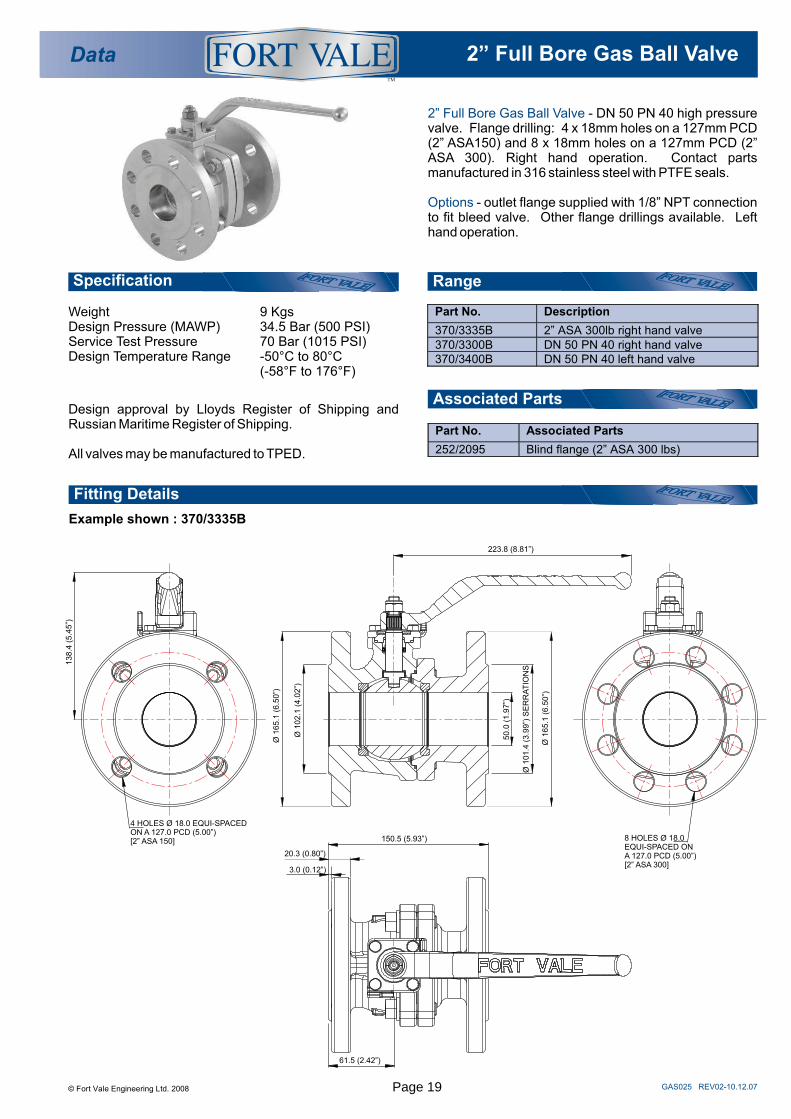
Example shown : 370/3335B
2” Full Bore Gas Ball Valve
Options
- DN 50 PN 40 high pressure valve. Flange drilling: 4 x 18mm holes on a 127mm PCD (2” ASA150) and 8 x 18mm holes on a 127mm PCD (2” ASA 300). Right hand operation. Contact parts manufactured in 316 stainless steel with PTFE seals.
- outlet flange supplied with 1/8” NPT connection to fit bleed valve. Other flange drillings available. Left hand operation.
Weight 9 KgsDesign Pressure (MAWP) 34.5 Bar (500 PSI)Service Test Pressure 70 Bar (1015 PSI)Design Temperature Range -50°C to 80°C
(-58°F to 176°F)
Design approval by Lloyds Register of Shipping and Russian Maritime Register of Shipping.
All valves may be manufactured to TPED.
Part No. Description
370/3335B 2” ASA 300lb right hand valve 370/3300B DN 50 PN 40 right hand valve 370/3400B DN 50 PN 40 left hand valve
Part No. Associated Parts
252/2095 Blind flange (2” ASA 300 lbs)
Data 2” Full Bore Gas Ball Valve TM
© Fort Vale Engineering Ltd. 2008
Ø 1
02.1
(4.0
2”)
Ø 1
65.1
(6.5
0”)
223.8 (8.81”)Ø
165.1
(6.5
0”)
50.0
(1
.97”)
Ø 1
01.4
(3.9
9”)
SE
RR
AT
ION
S
20.3 (0.80”)
3.0 (0.12”)
150.5 (5.93”)
61.5 (2.42”)
4 HOLES Ø 18.0 EQUI-SPACED ON A 127.0 PCD (5.00”) [2” ASA 150]
138.4
(5.4
5”)
8 HOLES Ø 18.0 EQUI-SPACED ON A 127.0 PCD (5.00”) [2” ASA 300]
Page 19

Parts drawing
Data 2” Full Bore Gas Ball ValveTM
GAS026 REV01-02.12.07
SEAL KITPart number 370/33SKB contains all parts marked
A detailed step-by-step maintenance manual is available for our gas ballvalve in both printed and CD formats. Please contact our Sales team for further information.
Item Description Part No.
1 M10 self locking nut 5112-008 2 M10 washer 5113-009 3 Handle 370/3306 4 Disc spring (3) 5113-038 5 M6 hex head bolt (4) 5111-022 6 M6 spring washer (4) 5113-008 7 Clamp plate 370/3305B 8 Neoprene washer 5005-216 9 Neoprene washer 5005-866N 10 Spindle bush 370/3307B 11 Bottom seal 359/2007 12 Bottom bush 370/3321 13 Spindle 370/3320 14 Ball valve body 370/3365 15 M12 stud (4) 370/3314 16 RTFE ball seal (2) 370/3302 17 50mm ball 370/3301 18 Body seal 370/3303 19 Ball valve body half 370/3316 20 M12 spring washer (4) 5113-010 21 M12 full nut (4) 5112-006
© Fort Vale Engineering Ltd. 2008
1
2
5
6
3
4
7
11
12
13
14
15
16
17
20
21
16
18
19
10
9
8
Page 20

ACMEOUTLETASSEMBLIES//
© Fort Vale Engineering Ltd. 2009 Page 21

ACME OUTLETASSEMBLIES//
Our are made to the modified ACME thread common on gas tank containers throughout the world.
In addition, the flange is equipped with a connection for a sample or bleed valve or a pressure gauge.
The outlet spigot has a bleed hole to relieve any remaining pressure in the outlet before the cap is removed - making this operation safe to the operative.
outlet flange connections
3
6
78
9
© Fort Vale Engineering Ltd. 2009 Page 22

Description Part No.
3.25” ACME outlet 252/2070 3.25” ACME dust cap 252/2075 3.25” ACME cap plug 252/2076 PTFE seal for 3.25” ACME dust cap 5005-877 Retaining ring clip for 3.25” ACME 5120-027 Captivating wire 425/0004
Description Part No.
1.75” ACME outlet 252/2080 1.75” ACME dust cap 252/2085 1.75” ACME cap plug 252/2086 PTFE seal for 1.75” ACME dust cap 5005-878 Retaining ring clip for 1.75” ACME 5120-028 Captivating wire 425/0004
Data ACME Outlet AssembliesTM
3.25” ACME Outlet Assembly
1.75” ACME Outlet Assembly
GAS029 REV01-10.12.07
PARTS LIST
PARTS LIST
This assembly is suitable for gas phase applications.
May be manufactured to TPED.
This assembly is suitable for liquid phase applications.
May be manufactured to TPED.
© Fort Vale Engineering Ltd. 2009
PART NUMBER : 252/2077
3.25” ACME outlet spigot complete with cap and PTFE seal. Drilled 4
x 18mm holes on a 127mm PCD. Manufactured in 316 stainless steel.
PART NUMBER : 252/2087
1.75” ACME outlet spigot complete with cap and PTFE seal. Drilled
4 x 18mm holes on a 127mm PCD. Manufactured in 316 stainless steel.
22.5°
4 HOLES Ø18.0 (0.71”) THRO EQUI-SPACED ON A 127.0 (5.00”) PCD.
50.8 (2.00”)
21.3
(0.8
4”)
68.4
(2.6
9”)
1.8
(0.0
7”)
Ø25.9 (1.02”)
Ø165.1 (6.50”)
Ø101.3 (3.99”)
1 HOLE 1/4” NPTX 0.39” DEEP
1.75” STUB ACME
73.3
(2.8
9”)
21.3
(0.8
4”)
1.8
(0.0
7”)
1 HOLE 1/4” NPTX 0.39” DEEP
Ø 50.0 (1.97”)
Ø 101.3 (3.99”) STD SERRATIONS
Ø 165.1 (6.50”)
3.25” STUB ACME
4 HOLES Ø18.0 (0.71”) THRO EQUI-SPACED ON A 127.0 (5.00”) PCD.
22.5°
88.9 (3.50”)
Page 23

THIS PAGE IS INTENTIONALLY BLANKPage 24

AFTERSALES//
>> Spares
>> Repairs
>> Maintenance
>> Distributors
© Fort Vale Engineering Ltd. 2009 Page 25

AFTER SALES//
The Fort Vale system does not stop at the supply of valves to tank manufacturers, we pride ourselves in
offering a worldwide to all our end users.
With Fort Vale subsidiaries in Texas USA, Rotterdam, Moscow, Shanghai and Singapore and a genuine
worldwide holding substantial stocks of spares at controlled retail prices, your container can be repaired anywhere with minimum down-time.
To ensure that your staff can be trained to repair our valves quickly and competently, we offer a series of
on compact disc. Each is illustrated with step-by-step photos and concise instructions on how to repair our products and test them before re-fitting.
Sets of specialist are also available to ensure that all seals are fitted correctly and without damage to the seal or the valve, which in turn keeps costs and down-time to a minimum.
after sales service
distributorship network
maintenance manuals
tools
© Fort Vale Engineering Ltd. 2009 Page 26

MAINTENANCE//
To help with the maintenance of your tanks, Fort Vale offers a Maintenance Manual on CD which includes a step-by-step photographic tutorial and states tool requirements for the whole range of gas valves fitted to your tank.
In addition, Fort Vale has an established worldwide network of distributors to help you with your spares logistics.
MMCD001REV00 -30.06.00//
IMO 5 Gas Tank EquipmentMaintenance Manual
© Fort Vale Engineering Ltd. 2009 Page 27

Fort Vale UKHead Office & Manufacturing PlantTel : +44 (0)1282 687120Fax : +44 (0)1282 687110Email : [email protected]
Fort Vale USATel : +1 281 471 8100Fax : +1 281 471 8116Email : [email protected]
Fort Vale NetherlandsTel : +31 (0)180 483333Fax : +31 (0)180 410797Email : [email protected]
Fort Vale Russian FederationTel : +7 916 682 0947Email : [email protected]
Fort Vale P.R. ChinaTel : +86 21 6442 1367Fax : +86 21 6442 1376Email : [email protected]
Fort Vale SingaporeTel : +65 6515 9950Fax : +65 6515 3034Email : [email protected]
Fort Vale AustraliaTel : +61 7 3310 4854Email : [email protected]
www.fortvale.com
All goods supplied will be subject to Fort Vale Engineering Ltd Terms and Conditions of Sale (Ref. FV4) which are available upon request, or may be viewed at www.fortvale.com.
Please note that this brochure and the contents herein remain the property of Fort Vale Engineering Limited.
This brochure may not be copied or reproduced, or the information contained herein divulged to any third party without the prior written permission of Fort Vale Engineering Limited.
Repair/refurbishment/resetting of Fort Vale valves may be carried out only by trained and authorised personnel. Fort Vale Engineering Limited shall not, in any circumstances, be liable for injuries, losses, expenses or damage, direct or consequential, sustained by the buyer or any person which may in any degree be attributable to the adoption, either by the buyer or any third party, of technical or other information, data or advice given on behalf of Fort Vale Engineering Limited or however otherwise caused in relation to the use of its products in accordance with Fort Vale Engineering Limited’s recommendation.
The specifications included in this catalogue are intended to be generic and must be interpreted as equivalent or functionally equivalent. The identification of many items is facilitated by illustrations (photographs and line drawings). The mention of, or reference to specific companies, national standards, or trade names, including those that might appear on the photographs, is intended for illustration purposes only. It does not imply an endorsement, preference or availability of any specific standard, brand or supplier.
The data and information contained herein is being provided for information only and without responsibility, and Fort Vale Engineering Limited makes no representations or warranties, either expressed or implied, as to the accuracy, completeness, or fitness for a particular purpose. Fort Vale Engineering Limited does not accept any responsibility or liability with regard to the reliance on, or use of this data and information.
REV10_19.03.18
®
© Fort Vale Engineering Ltd. 2018