CORBA vs. DCOM - Personliga hemsidor på KTHmaguire/DEGREE-PROJECT-REPORTS/010111... · CORBA vs....
123
Master’s Thesis in Computer Science Preliminary version December 21, 2000 CORBA vs. DCOM Fredrik Janson and Margareta Zetterquist The Royal Institute of Technology Kungliga Tekniska Högskolan Examiner: Prof. Seif Haridi Department of Teleinformatics The Royal Institute of Technology Supervisors: Vladimir Vlassov Department of Teleinformatics The Royal Institute of Technology Håkan Lundblad Adcore Creative AB Dan Thelin Adcore Creative AB
Transcript of CORBA vs. DCOM - Personliga hemsidor på KTHmaguire/DEGREE-PROJECT-REPORTS/010111... · CORBA vs....

Master’s Thesis in Computer Science Preliminary version December 21, 2000
CORBA vs. DCOM
Fredrik Janson and Margareta Zetterquist The Royal Institute of Technology
Kungliga Tekniska Högskolan Examiner: Prof. Seif Haridi
Department of Teleinformatics The Royal Institute of Technology Supervisors: Vladimir Vlassov Department of Teleinformatics
The Royal Institute of Technology
Håkan Lundblad Adcore Creative AB Dan Thelin Adcore Creative AB

CORBA vs. DCOM i
Abstract
Object oriented technology was focused on single-user environment for many years. As applications grew to become more complex and client/server technology emerged, there was a need to have shared objects in multi-users environment. One solution is the use of distributed objects, where objects executing in multiple computers interact over the network to participate in application processes. This architecture allows the workload to be distributed and it also allows independently developed solutions implemented in different environment and platform to interact with each other. To simplify network programming and to realize component-based software architecture, two distributed object models have emerged as standards, Object Management Group’s (OMG) Common Object Request Broker Architecture (CORBA) and Microsoft’s Distributed Component Object Model (DCOM). In order to make the right choice between these technologies, both technologies were thoroughly described and compared along with practical performance tests. The ease of deployment was also considered. The conclusions are that the performance between CORBA and DCOM is almost equivalent. CORBA is the dominant remoting architecture, connecting large-scale enterprise systems, which demands integration with legacy systems. DCOM is part of COM+, which is the dominant component architecture, operating mainly on the Windows platforms. We believe that in the future, both technologies will coexist and cooperate.

CORBA vs. DCOM ii
Summary of Contents
1 Introduction............................................................................................................ 1 Part 1: Overview of CORBA and DCOM 2 Existing implementation approaches to distributed computing............................. 4 3 An overview of CORBA and Enterprise JavaBeans ............................................. 7 4 An overview of DCOM and COM+ .................................................................... 31 Part 2: CORBA and DCOM/COM+ side by side 5 CORBA and DCOM/COM+ side by side ........................................................... 46 Part 3: Evaluation of CORBA and DCOM/COM+ 6 Introduction of the tests ....................................................................................... 76 7 The tests ............................................................................................................... 81 8 Test results ........................................................................................................... 93 Conclusions 9 Conclusions........................................................................................................ 106 10 References...................................................................................................... 111

CORBA vs. DCOM iii
Contents 1 Introduction............................................................................................................ 1
1.1 Background of the problem ........................................................................... 1 1.1.1 Why use distributed computing? ........................................................... 1
1.2 Problem statement and the objective of the master project ........................... 1 1.3 Structure of the thesis .................................................................................... 2
Part 1: Overview of CORBA and DCOM 2 Existing implementation approaches to distributed computing............................. 4
2.1 Remote Procedure Call (RPC)....................................................................... 4 2.2 Distributed objects ......................................................................................... 5 2.3 Components ................................................................................................... 5
3 An overview of CORBA and Enterprise JavaBeans ............................................. 7 3.1 Overview of CORBA .................................................................................... 7 3.2 The layer structuring in CORBA................................................................... 8
3.2.1 The top layer .......................................................................................... 8 3.2.1.1 CORBA object................................................................................... 9 3.2.1.2 Object reference............................................................................... 10 3.2.1.3 Interface Definition Language (IDL)............................................... 11 3.2.1.4 Object Request Broker (ORB)......................................................... 12 3.2.1.5 Object activation at the top layer using Visibroker ......................... 12 3.2.1.6 Method invocation at the top layer using Visibroker ...................... 13
3.2.2 The middle layer .................................................................................. 14 3.2.2.1 Interface Repository (IR)................................................................. 15 3.2.2.2 Implementation repository............................................................... 15 3.2.2.3 Static Invocation Interface (SII) ...................................................... 16 3.2.2.4 Dynamic Invocation Interface (DII) ................................................ 16 3.2.2.5 IDL skeletons................................................................................... 17 3.2.2.6 Dynamic Skeleton Interface (DSI) .................................................. 17 3.2.2.7 Object Adapter (OA) ....................................................................... 18 3.2.2.8 Basic Object Adaptor (BOA)........................................................... 19 3.2.2.9 Portable Object Adaptor (POA)....................................................... 19 3.2.2.10 Object activation at the middle layer using Visibroker with the Smart Agent ..................................................................................................... 21 3.2.2.11 Method invocation at the middle layer using Visibroker with the Smart Agent ..................................................................................................... 21
3.2.3 The bottom layer.................................................................................. 21 3.2.3.1 General Inter-ORB Protocol (GIOP) and Internet Inter-ORB Protocol (IIOP) ................................................................................................ 21 3.2.3.2 Object activation at the bottom layer using Visibroker with the Smart Agent ..................................................................................................... 23 3.2.3.3 Method invocation at the bottom layer using Visibroker with the Smart Agent ..................................................................................................... 23
3.3 Thread management and objects by value................................................... 23 3.3.1 Threads in Inprise Visibroker .............................................................. 23
3.3.1.1 Thread pooling................................................................................. 23 3.3.1.2 Thread-per-session........................................................................... 23
3.3.2 Objects passed by value....................................................................... 24

CORBA vs. DCOM iv
3.4 Overview of Enterprise JavaBeans.............................................................. 24 3.4.1 Enterprise JavaBeans component model ............................................. 24 3.4.2 A typical EJB architecture ................................................................... 25
3.4.2.1 The application server...................................................................... 25 3.4.2.2 The EJB server................................................................................. 25 3.4.2.3 The EJB container............................................................................ 26
3.4.3 Session and entity beans ...................................................................... 27 3.4.3.1 Session beans ................................................................................... 27 3.4.3.2 Entity beans ..................................................................................... 27
3.4.4 Enterprise JavaBeans deployment and packaging............................... 28 3.4.4.1 Deployment...................................................................................... 28 3.4.4.2 Packaging......................................................................................... 28
3.4.5 EJB with the BEA Weblogic Server 5.1.............................................. 28 3.4.5.1 The Enterprise JavaBeans client/server development process using WebLogic Server 5.1 and Visual Café 4 ......................................................... 28 3.4.5.2 Transaction management using WebLogic Server 5.1 .................... 29 3.4.5.3 Database access from Weblogic with EJB ...................................... 29
3.4.6 CORBA and EJB ................................................................................. 29 3.4.7 Using Weblogic with RMI over IIOP with Visibroker 4.1 ................. 30
4 An overview of DCOM and COM+ .................................................................... 31 4.1 Overview of COM ....................................................................................... 31
4.1.1 What are a COM client and a COM server?........................................ 31 4.2 Overview of DCOM .................................................................................... 31 4.3 The layer structuring in DCOM................................................................... 32
4.3.1 The top layer in DCOM....................................................................... 32 4.3.1.1 The COM Library ............................................................................ 33 4.3.1.2 UUID/GUID and ProgID................................................................. 33 4.3.1.3 The Windows Registry .................................................................... 34 4.3.1.4 Object creation................................................................................. 34 4.3.1.5 Interface pointer............................................................................... 34 4.3.1.6 COM Library services to the client ................................................. 34 4.3.1.7 How a remote object is instantiated................................................. 35 4.3.1.8 Locating and requesting a remote object ......................................... 35 4.3.1.9 How does the client determine the CLSID? .................................... 35 4.3.1.10 Releasing the object ..................................................................... 36 4.3.1.11 Interface Definition Language (IDL)........................................... 36 4.3.1.12 Exposing a server object implementation.................................... 36 4.3.1.13 The COM Library’s service to the server .................................... 36 4.3.1.14 The Class Factory ........................................................................ 36 4.3.1.15 Registering a COM server object ................................................ 37 4.3.1.16 Object activation at the top layer ................................................. 37 4.3.1.17 Method invocation at the top layer .............................................. 38
4.3.2 The middle layer in DCOM................................................................. 38 4.3.2.1 Proxy................................................................................................ 38 4.3.2.2 Stub .................................................................................................. 39 4.3.2.3 The RPC Channel ............................................................................ 39 4.3.2.4 Service Control Manager (SCM)..................................................... 40 4.3.2.5 Object activation at the middle layer ............................................... 40 4.3.2.6 Method invocation at the middle layer ............................................ 41
4.3.3 The bottom layer in DCOM................................................................. 41

CORBA vs. DCOM v
4.3.3.1 DCE RPC / ORPC ........................................................................... 41 4.3.3.2 Reference counting and pinging ...................................................... 42 4.3.3.3 IPID, OXID and OBJREF ............................................................... 42 4.3.3.4 OXID Resolver ................................................................................ 43 4.3.3.5 Object activation at the bottom layer............................................... 43 4.3.3.6 Method invocation at the bottom layer ............................................ 43
4.4 Overview of COM+..................................................................................... 44 Part 2: CORBA and DCOM/COM+ side by side 5 CORBA and DCOM/COM+ side by side ........................................................... 46
5.1 Object model................................................................................................ 46 5.1.1 CORBA................................................................................................ 46 5.1.2 DCOM ................................................................................................. 47
5.2 Services........................................................................................................ 48 5.2.1 CORBA................................................................................................ 48
5.2.1.1 Transaction service .......................................................................... 49 5.2.1.2 Security service................................................................................ 51 5.2.1.3 Event and notification service ......................................................... 53 5.2.1.4 Naming service ................................................................................ 53 5.2.1.5 Visibroker services .......................................................................... 54
5.2.2 COM+.................................................................................................. 58 5.2.3 Summary.............................................................................................. 62
5.3 Scalability .................................................................................................... 62 5.3.1 CORBA................................................................................................ 62 5.3.2 COM+.................................................................................................. 63
5.4 Fault tolerance and availability.................................................................... 64 5.4.1 CORBA................................................................................................ 64 5.4.2 COM+.................................................................................................. 65
5.5 Deployment.................................................................................................. 66 5.5.1 Openness.............................................................................................. 66 5.5.2 Development platforms ....................................................................... 66 5.5.3 Development tools ............................................................................... 67 5.5.4 Ease of deployment.............................................................................. 67
5.5.4.1 Ease of deployment vs. control........................................................ 68 5.5.5 Learning curve ..................................................................................... 68
5.6 Financial considerations .............................................................................. 68 5.7 In the future.................................................................................................. 69 5.8 Code example .............................................................................................. 69
5.8.1 CORBA code example using Visibroker 4.1 for Java......................... 69 5.8.2 COM+ code example using Visual J++ 6.0......................................... 73
Part 3: Evaluation of CORBA and DCOM/COM+ 6 Introduction of the tests ....................................................................................... 76
6.1 Simple tests.................................................................................................. 76 6.2 A real application – an On-Line Transaction Processing (OLTP) application 77 6.3 Time model for the tests with assumptions ................................................. 77
7 The tests ............................................................................................................... 81

CORBA vs. DCOM vi
7.1 Invocation Speed ......................................................................................... 81 7.2 Passing Input Parameters ............................................................................. 82 7.3 First Call Overhead...................................................................................... 83 7.4 Remote Counter ........................................................................................... 84 7.5 Multi Clients ................................................................................................ 85 7.6 The Debit Credit test.................................................................................... 87 7.7 The test environment ................................................................................... 90
7.7.1 Simple tests.......................................................................................... 90 7.7.1.1 Hardware.......................................................................................... 90 7.7.1.2 Software........................................................................................... 90
7.7.2 Debit Credit ......................................................................................... 91 7.7.2.1 Hardware.......................................................................................... 91 7.7.2.2 Software........................................................................................... 91
8 Test results ........................................................................................................... 93 8.1 Invocation Speed ......................................................................................... 93 8.2 Passing Input Parameters ............................................................................. 95 8.3 First Call Overhead...................................................................................... 96 8.4 Remote Counter ........................................................................................... 97 8.5 Multi Clients ................................................................................................ 98 8.6 Debit Credit ............................................................................................... 100 8.7 Additional tests .......................................................................................... 103
Conclusions 9 Conclusions........................................................................................................ 106
9.1 COM+, the dominant component architecture, vs. CORBA, the dominant remoting architecture ............................................................................................. 106 9.2 Strategic direction...................................................................................... 106 9.3 Decision guidelines.................................................................................... 107
9.3.1 An assessment strategy ...................................................................... 108 10 References...................................................................................................... 111
10.1 Other resources used.................................................................................. 114

CORBA vs. DCOM vii
List of figures
Figure 1: The RPC structure...................................................................................... 4 Figure 2: A request is passed from a client to an object implementation. ................ 8 Figure 3: A request is passed from client to object implementation at the top layer.9 Figure 4: IDL language mappings........................................................................... 11 Figure 5: Structure of the Object Request Broker (ORB) with clients and object implementations at the middle layer............................................................................ 14 Figure 6: Request delivered through dynamic skeleton. ......................................... 18 Figure 7: An overview of the POA architecture used in Visibroker ....................... 19 Figure 8: A typical EJB architecture. ...................................................................... 25 Figure 9: The EJB container.................................................................................... 26 Figure 10: The different types of COM servers .................................................... 31 Figure 11: The Class Factory manufacturing an object. ....................................... 37 Figure 12: Components of interprocess communication....................................... 39 Figure 13: The SCM contacts the server side SCM to create a remote object...... 40 Figure 14: An example of the ORPC in the OSI model........................................ 42 Figure 15: Major components and interfaces of the Transaction Service............. 50 Figure 16: The SSL used with CORBA................................................................ 52 Figure 17: Supplier-consumer communication model. ......................................... 56 Figure 18: Binding, resolving, and using an object name from a naming context within a namespace...................................................................................................... 58 Figure 19: The scenario when a publisher fires an event ...................................... 61 Figure 20: A client making a request to a server................................................... 77 Figure 21: Time passed on the client and servant side when making N requests. ... 79 Figure 22: Schematic model of the Invocation Speed test. ................................... 81 Figure 23: Schematic model of the Passing Input Parameters test ....................... 82 Figure 24: Schematic model of the First Call Overhead test. ............................... 84 Figure 25: Schematic model of the Remote Counter test...................................... 85 Figure 26: Schematic model of the Multi Clients test in CORBA........................ 86 Figure 27: Schematic model of the Multi Clients test in COM. ........................... 87 Figure 28: The CORBA architecture in the Debit Credit test. .............................. 89 Figure 29: The DCOM architecture in the Debit Credit test................................. 90 Figure 30: The Invocation Speed test results for CORBA with BY_POA and BY_INSTANCE policy. .............................................................................................. 94 Figure 31: The Invocation Speed test results. ....................................................... 94 Figure 32: The Passing Input Parameters test results............................................ 95 Figure 33: The First Call Overhead test results..................................................... 96 Figure 34: The Remote Counter test results.......................................................... 97 Figure 35: The MultiClients test results with 1kB array size................................ 98 Figure 36: The MultiClients test results with 4kB array size................................ 99 Figure 37: The Debit Credit - Throughput test results for 1tps........................... 100 Figure 38: The Debit Credit - Throughput test results for 2tps........................... 101 Figure 39: The Debit Credit – Response time test results for 1tps. .................... 102 Figure 40: The Debit Credit - Throughput test results for 2tps........................... 102 Figure 41: The Debit Credit – Additional tests for 1tps...................................... 104 Figure 42: Assessment example.......................................................................... 110

CORBA vs. DCOM viii
List of tables Table 1: The tests 76 Table 2: Some CORBA IDL to Java Mappings 83 Table 3. Some DCOM IDL to Java Mappings 83

CORBA vs. DCOM 1
1 Introduction
1.1 Background of the problem Object oriented technology was focused on single-user environment for many years. As applications grew to become more complex and client/server technology emerged, there was a need to have shared objects in multi-users environment. One solution is the use of distributed objects, where objects executing in multiple computers interact over the network to participate in application processes. This architecture allows the workload to be distributed and it also allows independently developed solutions implemented in different environment and platform to interact with each other.
1.1.1 Why use distributed computing? By nature some applications are distributed, here are some reasons:
• The data are distributed. • The computation is distributed. • The users of the application are distributed.
The data are distributed The data may be distributed over multiple machines because of ownership and administrative reasons. The data may be accessed remotely but not stored locally. The computation is distributed A program may need multiple processors executing in parallel to solve a computation. Other applications may want to use a specific feature of a system that is not provided by their own. The users of the application are distributed Multiple users use an application and communicate using the application. Each user executes a piece of the distributed application on his or her computer, and shared objects, typically execute on one or more servers.
1.2 Problem statement and the objective of the master project
To simplify network programming and to realize component-based software architecture, two distributed object models have emerged as standards, Microsoft’s Distributed Component Object Model (DCOM) and Object Management Group’s (OMG) Common Object Request Broker Architecture (CORBA). The selection of Microsoft’s DCOM or OMG’s CORBA as an architecture will affect the tools, applications, and development process. It is important to know the differences between these two competing architectures for distributed objects in order to make the right choice. With this background a master project is specified where DCOM and CORBA will be compared and evaluated side by side, step by step and layer by layer. The problem definition is as follows: • The employees at Adcore Creative AB should get better knowledge about the
component models Enterprise JavaBeans™ and COM+.

CORBA vs. DCOM 2
• The company should get a decision framework based on a comparison between OMG’s CORBA and Microsoft’s DCOM. This thesis should give guidelines for which distributed model that should be chosen for a given kind of system that is going to be implemented.
This master project should serve Adcore Creative AB with a decision framework for choosing between those architectures. Programmers mastering one side of this comparison should get an overview of the other. The master project should also give an overview of the two component technologies Javasoft’s Enterprise JavaBeans™ (EJB) and Microsoft’s COM+.
1.3 Structure of the thesis The remainder of this thesis is organized as follows. The report is divided in three parts and conclusions. Part 1 – Overview of CORBA and DCOM The both technologies are thoroughly described, devided in the two following threads:
Overview of CORBA and Enterprise JavaBeans This Section thoroughly describes CORBA and gives and overview of Enterprise JavaBeans.
Overview of DCOM and COM+ This Section thoroughly describes DCOM and gives and overview of COM+.
Part 2 – CORBA and DCOM/COM+ side by side In Section CORBA and DCOM/COM+, the both technologies are compared based on:
• Object models • Services • Scalability • Fault tolerance and availability • Deployment • Financial considerations • CORBA and COM+ in the future • CORBA and COM+ code example
Part 3 – Evaluation of CORBA and DCOM/COM+ The both technologies are evaluated using test applications implemented as part of the thesis project. Conclusions The conclusions from the comparisons and the evaluation are presented.

CORBA vs. DCOM 3
Part 1: Overview of CORBA and DCOM

CORBA vs. DCOM 4
2 Existing implementation approaches to distributed computing
There are several existing implementation approaches to distributed computing such as:
• Distributed objects (CORBA and DCOM) and components (Enterprise JavaBeans and COM+). With distributed objects and components, a method is called within an object.
• Remote Procedure Call (RPC). A protocol used for implementing the client-server model. With RPC, a specific function is called.
• HTTP/Common Gateway Interface (CGI). Client/server middleware primarily designed to serve documents. With the introduction of CGI the Web evolved from a URL-based file server to a more mature 3-tier client/server middleware. According to [20], HTTP with CGI is a slow protocol. It is not suitable for writing modern client/server applications as opposed to distributed objects.
The protocol Remote Procedure Call (RPC), distributed objects and components are described below.
2.1 Remote Procedure Call (RPC) Remote Procedure Call (RPC) enables programs to do remote procedure invocation, i.e. call a function in another process which possibly resides on another host in a network. The programmers get to some extent a transparent view of the network. The details on how messages are sent are hidden for the them. Figure 1 from [4] shows a typical RPC structure. According to [4], the RPC structure can be divided into three layers; the top the middle and the bottom layer.
Client Server
Network
Client stub
Wire protocol
Server stub
Wire protocol
Middle layer
Bottom layer
Top layer
operation()
reply
Figure 1: The RPC structure The top layer consists of the client and server programmers’ point of view, who do not have bother whether a method call is local or remote. To the programmer a remote call looks just like a regular local call. The lower layers “hide” the physical location of the implementation of the function from the calling program.

CORBA vs. DCOM 5
The middle layer transparently makes procedure calls meaningful across different processes. To call a remote procedure the client calls the client stub, which acts as a local stand in for the server side procedure. At the server side the call is forwarded to the server stub which calls the actual procedure. Both the call parameters and the return value of the function has to be sent in messages over the network. The middle layer conducts the wrapping/unwrapping of the information into messages of a suitable format to be sent over the network. At the sender the information is wrapped to a message and at the receiver the message is unwrapped into its proper format. The technique to pack the data into the appropriate network format is called marshalling, and the reverse process that unpacks the packet is called unmarshalling. Marshalling and unmarshalling is conducted by the stubs. The bottom layer consists of the wire protocol which ships the marshaled messages between the stubs.
2.2 Distributed objects The distributed object technology aims to utilise the concepts from object-oriented programming into distributed computing and extend object-orientation into the area of client/server programming, as discussed in [21]. A distributed object is like an ordinary object with the difference that can be put anywhere in a network and can be reached from any other process which wants to utilise that object. The physical location of a distributed object should be totally hidden from the user who does not have to care whether an object is distributed or not. To the user the usage should look the same, i.e. a distributed object should be treated as a classic local object. Distributed objects can reside not only different processes at the same host but also at different hosts and be reached via the network. One important part in a distributed object system is the functionality which lets the objects communicate with eachother irrespective of where they are located. The distributed object system is hiding objects’ locations and lets programmers use the remote objects just as easily as they use classic local objects. Distributed objects can be packaged into components, see the Section 2.3 to read more about components and the benefits of component-based architecture.
2.3 Components According to [21], a component is a blob of software that is not bound to a particular program, computer language or implementation. A component has a well-specified interface and a component can be invoked as an object across address spaces, networks, languages, operating systems and tools. A client use a component by calling one of the methods in its interface that does the service that the client wishes. It is a system-independent software entity. It is a reusable, self-contained piece of software that is independent of any application.

CORBA vs. DCOM 6
Both distributed objects and components can be viewed as blobs of software on a network that can be asked to do things for the user. However, there are the following three differences between the two as discussed in [26].
1. Component technology is a packing technology, not an implementation technology. Any programming language is possible to use to implement a component; it does not need to be an object-oriented language. The component technology packs the blob of software so a client can use it.
2. Components are language neutral. A client programmer should not have to know what programming language the component was written in, the client programmer and the component programmer can choose whatever languages they desire.
3. Components are encapsulated in a stronger way than objects. The component’s interface describes only behaviors, and had no syntax to describe implementations of those behaviors. (In some object-oriented programming languages both the definition and implementation of behaviors of an object can be found in the same file.)
Component technology promises to radically alter the way software systems are developed. For example, distributed objects packaged as components allow developers to put together complex client/server information systems by simply assembling and extending components, like plug-and-play. A big application and the components it consists of can be developed in small steps and be reused, which makes the job easier for the developers. (Note that not all components are objects, nor are they all distributed.)

CORBA vs. DCOM 7
3 An overview of CORBA and Enterprise JavaBeans
3.1 Overview of CORBA CORBA (Common Object Request Broker Architecture) is a distributed object framework proposed by a consortium of over 800 companies called the Object Management Group (OMG), founded in 1989. The member organisations are ranging from larger companies to smaller ones. Some of the members are Sun Microsystems and Inprise Software Corporation. CORBA serves as a specification of middleware for distributed objects. The specification does not state how the implementation should be done, there are several commercial products that implements the CORBA standard. This has both advantages and disadvantages. Many companies cooperate and share their experiences which contributes to a better and improved standard. It also has its drawbacks when multiple vendors’ implementations are about to communicate, which is very common in a distributed environment. Vague specifications force vendors to draw their own conclusions which gives many differenent implemetations. As the specifications become more clear, the different implementations converge and become more compatible. A CORBA-based program from any vendor, on almost any computer, operating system, programming language, and network, can interoperate with a CORBA-based program from the same or another vendor, on almost any other computer, operating system, programming language, and network. CORBA uses object orientation in its architecture. The objects are pieces of running software that can live anywhere on a network. Its platform, location and implementation are of no interest for the client; in fact those details are hidden for the user. What the client is interested in is the interface of its server object. This interface is the handshake between clients and servers. CORBA uses IDL (Interface Definition Language) to define these contracts as described in [7]. The CORBA IDL is a declarative language, which means that it contains no implementation details. It is independent of the programming language and maps to programming languages via a set of OMG standards. OMG has developed standardized mappings for C, C++, Java, COBOL, Smalltalk, Ada, Lisp, Python, and IDLscript. When compiling the IDL interface it generates the client stub and the server skeleton. On top of the IDL stub the programmer implements the client and on the IDL skeleton the object implementation. The stubs and skeletons serve as proxies for clients and servers, respectively. Figure 2 below shows a very simple view of a client making a request. A client that wishes to perform an operation on the object sends a request. The client’s request is passed through the stub on the client side and continues via an ORB (Object Request Broker) and the skeleton on the implementation side to the object where it is executed. The ORB is the core or the “heartbeat” of the CORBA system. Its responsibility is to find an object implementation for the request, prepare the object implementation to receive the request and to pass the data that makes the request. It serves as a bus for objects and lets them make requests and receive responses from other objects located locally or remotely.

CORBA vs. DCOM 8
Figure 2: A request is passed from a client to an object implementation.
The details of the functionality and architecture behind this request have been studied in three different layers:
• The top layer. The programmers view and the basic programming architecure. • The middle layer. The remoting architecture, that provides the client
programmer with the freedom not to have to know where an object is located in a network.
• The bottom layer. The wire protocol architecture. As metioned above, there are several ORB implementations among which the Inprise Visibroker [29] ORB is one of the most widely used. This ORB is the one that has been studied in more detail.
3.2 The layer structuring in CORBA Based on the RPC structure described in Section 2.1, three layers are used to describe the architecture of CORBA. The first layer, the top layer, referred to as the basic programming architecture, describes the programmers’ view of CORBA. The middle layer, the remoting architecture, describes the required infrastructure to give both the client and the server the illusion that they reside in the same address space. The last layer, the bottom layer, describes the wire protocol architecture necessary for supporting the client and the server to run on different machines. Looking at method invocations and object activation, the different parts of the CORBA architecture are described at the three layers. The layer structuring in CORBA is described using the ORB implementation from Inprise called Visibroker, based on CORBA specification 2.3.1 [7]. Describing an actual implementation of the specification for CORBA makes the description more concrete and hopefully easier to understand.
3.2.1 The top layer This layer corresponds to the programmers’ view of the CORBA architecture. The Figure 3 below shows the top layer of the CORBA architecture.
Client
Request Object Request Broker (ORB)
Object implementation

CORBA vs. DCOM 9
Object Request Broker (ORB)
Clients Object Implementations
Figure 3: A request is passed from client to object implementation at the top layer. Client side On the client side, the client requests a CORBA object and invokes its methods. For a client to invoke methods on an object, it first needs a handle to the object. In CORBA, this handle is called an object reference. The process to obtain an object reference is called binding. The details of the connection between the client and the server are totally hidden from the programmers and the client and server interact as if they reside on the same machine. The client only sees the object’s interface, no implementation details. Clients interact with a CORBA object by invoking its methods described in the Interface Definition Language (IDL). The IDL serves as contract between the client and the server. The client’s request does not pass directly from the client to object implementation; it is passed via the Object Request Broker (ORB) to the server. The ORB works as a communication link between the client and server. Server side The server creates an instance of an object and makes it available to the client by registering it with the ORB.
3.2.1.1 CORBA object As stated in [20], a CORBA object is a blob of intelligence that can live anywhere on the network. It is packaged as a binary component, which clients can invoke via method invocations. There are four keys which helps to describe a CORBA object:
• Encapsulation. An encapsulated CORBA object consists of two parts: the interface and its implementation. The interface is presented for the clients and the implementation is kept private. The interface serves as a contract between the client and server.
• Inheritance. Inheritance saves a lot of work for the programmers. CORBA uses inheritance in the IDL, interface inheritance.

CORBA vs. DCOM 10
• Polymorphism. Polymorphism is to have some operations that belong to more than one kind of object. A client invoking the same operation on a set of objects results in different things happening.
• Instantiation. Instantiation of a CORBA object is the creation of a new individual object instance.
By publishing its interface to the outside world, the CORBA object shows its methods and makes it available for requests. Clients do not need to know where the object resides and what operating system it executes on. Also the details of how the object is implemented is of no interest for the client. The client acts as if the object always exist, maintainning its state between invocations. In reality computing resources may not be allocated for an object until an invocation comes in. The allocated resources may be deallocated after the invocation has completed. The state between invocations is maintained on persistent storage and is loaded on activation.
3.2.1.2 Object reference An object reference is the reference clients use to connect to an object. Every CORBA object in a system has, regardless of its lifetime, its own object reference. The object reference is valid until the object is explicitly deleted. The lifetime of a CORBA object depends on its purpose. A CORBA object representing a main account object for an enterprise’s net worth must outlive the enterprise’s existence, while a CORBA object representing a shopping cart on webshop only outlives a shopping round. In a Portable Object Adaptor (POA) based ORB, the object reference is created at the server side, since its server related. The ORB described later in this Section assigns the reference at object creation and the persistent services use it to save an object’s state so that it can be reactivated at a later time. The name “object reference” is very generic, when different ORBs are about to communicate the “Interoperable Object Reference” (IOR) is a better name. The IOR is understood by different ORBs, which interoperate using the protocol Internet Inter-ORB Protocol (IIOP), described at the middle layer see Section 3.2.2. The contents of the object reference are of no interest for the client, in fact only the ORB can change it. To really explain the object reference, details hidden from the programmer are required. The object reference must contain enough information for the client-side ORB to find back to server code. Without diving into details at this layer, according to [25], an object reference contains three pieces of information: An address and two pieces that are important for the server programmer:
1. An address. The address is required so that the client ORB can find the right machine.
2. The name of the POA. The name uniquely identifies a POA. A request from a client will come to the same POA that created the object reference. The POA serves as an intermediary between the implementation of an object and the ORB, for more details read about the POA at the middle layer see Section 3.2.2.
3. The object Id. This used by the POA to identify the object implementation corresponding to the request.

CORBA vs. DCOM 11
A client can stringify an object reference using the method object_to_string(). This stringified object reference can be stored and reactivated at a later time using the method string_to_object(). The stringified version is valid as long as the object it refers to has not been deleted. All ORBs must provide the same language mapping to an object reference for a particular programming language. This makes it possible to pass a stringified object reference to any other instance of the same vendor’s ORB and in addition to any other IIOP ORB. Since these stringified references can be passed by email, storage in databases and even by fax, it is the most popular way of passing object references. In Visibroker, an IOR can also be associated with an URL in the form of a string in a file. This feature is called the URL Naming Service, which allows clients to locate objects using an URL.
3.2.1.3 Interface Definition Language (IDL) The interfaces can be defined statically using an interface definition language, called the OMG Interface Definition Language (OMG IDL). The IDL serves as a contract between clients and the associated object services. It defines the objects methods and the parameters to those operations. An interface in IDL is equivalent of a class in C++ or an interface in Java and it obeys the same lexical rules as in C++. IDL interfaces can be written in and invoked from any language, supporting CORBA bindings. This means that client and server objects written in different languages can interoperate. Some of the mappings to programming languages are shown in Figure 41.
Figure 4: IDL language mappings.
The IDL is a purely declarative language, which means that it does not provide implementation details; it separates the interface and the implementation. One of the most important features of IDL is that it supports single and multiple inheritance. Using this, an interface can be derived from one or more existing interfaces, saving a lot of work for the programmer. OMG IDL can also specify exceptions. After the IDL is defined, vendor-specific tools can be utilized to generate the client-side stubs and the server-side skeletons, which are used when a request is passed from client to server. More details are available at the middle layer.
1 Page 8 in [3]
Smalltalk
C++
Java
Ada
Cobal
OLE
Target object

CORBA vs. DCOM 12
3.2.1.4 Object Request Broker (ORB) The ORB is used when a request is sent by a client that wishes to perform an operation on an object. The ORBs responsibility is to find an object implementation for that request, prepare the object implementation to receive the request and to pass the data that makes the request. The ORB serves as a communication link between the client and the server. The interface the client is presented is independent of where the object is located and what programming language it is implemented in. An ORB provides a variety of distributed middleware services. It lets objects discover each other at run time and invoke each other’s services. The best way to describe the ORB is to describe some of the middleware features it provides:
• Static and dynamic method invocations. The ORB lets the programmer define the methods at compile time or dynamically at run time.
• High-level language bindings. The ORB makes it possible to use different languages to implement server objects. It is possible to call objects across language and operating system boundaries.
• Self-describing system. CORBA provides run-time metadata for describing every server interface that the system has knowledge about. This helps clients to invoke services at run-time and helps tools generate code “on-the-fly”.
• Local/remote transparency. An ORB has the capability to run standalone on a laptop or it can be interconnected with other ORBs using the protocol IIOP. An ORB can manage interobject calls within a single process, multiple processes within the same machine or across networks and operating systems. Either way it is totally transparent to the objects.
• Built-in security and transactions. The messages produced by the ORB include context information to handle security and transactions across machine and ORB boundaries.
• Coexistence with existing systems. The separation of interface and implementation is useful when integrating existing applications. Even if the application is implemented in stored procedures, the programmer can make it look like an object on the ORB.
3.2.1.5 Object activation at the top layer using Visibroker Client side
1. The client explicitly initialises the ORB. 2. To obtain a reference to the remote object, the client calls the static bind()
method. Server side
1. The server explicitly initialises the ORB. 2. The POA is created and configured. 3. The POA manager is activated to tell the ORB that it is ready to accept client
requests. 4. Objects are activated. 5. The server waits for client requests.
Initialise the ORB The ORB provides a communication link between client requests and object implementations. Both sides must initialise it before communicating with it.

CORBA vs. DCOM 13
Create and set-up the POA The POA decides which servant that should be used for a client request. The following steps describe the way setting up the POA with a servant:
• Obtain a reference to the rootPOA. The rootPOA is the default POA that always is created. The rootPOA’s policies are predefined and cannot be changed. A policy is an object that controls the behaviour and the objects the POA manages. To create a new POA with other policies than the default rootPOA, a server application must get a reference to the rootPOA.
• Define the POA policies for the new POA. An example of a policy is
the lifespan policy, which specifies how the POA should control the lifecycle of an object implementation. The lifespan policy can be set to transient or persistent. The transient policy means that an object cannot outlive the POA that created it. The persistent policy means that the object can outlive the process in which it was created. A request invoked on a persistent object may result in a reactivation of the whole environment required for the object.
• Create a new POA with the defined policies as a child of the rootPOA.
Activate the POA through its manager The POA manager is default in the holding state, i.e. all requests coming from the client are queued. To activate the POA, the POA manager’s state is changed from a holding state to an active state. Activate objects Objects can be activated in several ways:
• Explicit: All objects are activated upon start-up. • On-demand: The servant manager, described at the middle layer, activates an
object upon receiving a request. • Implicit: Objects are implicitly activated by the server in response to an
operation by the POA. • Default servant: The POA uses the default servant to serve client requests.
This means that the same servant is used for all requests. Wait for requests Once the POA is set up, the server can wait for client requests. This will run until the server is terminated.
3.2.1.6 Method invocation at the top layer using Visibroker Client side The client invokes a method on the remote object using the retrieved object reference. Server side The request is processed by the server.

CORBA vs. DCOM 14
3.2.2 The middle layer The Figure 52 below shows the architecture at the middle layer, necessary for providing the client and the server with the illusion that they are in the same address space. The arrows in the figure represent the interfaces between ORB components and its clients and object implementations.
Interface repository
Object Request Broker
DynamicInvocationInterface
ORBinterface
StaticIDL
StubsPortable Object Adapter
StaticIDL
Skeletons
DynamicSkeletonInterface
Clients Object Implementations
Figure 5: Structure of the Object Request Broker (ORB) with clients and object
implementations at the middle layer. Client side When a client initiates a request, it retrieves the objects interface from the interface repository, which provides a secure, stateful, persistent memory for interface definitions. Once the client has found the object’s interface it searches the implementation repository for the object’s implementation. The interface and implementation repositories can be accessed directly via the ORB interface and indirectly through method invocations via the Static Invocation Interface (SII) and Dynamic Invocation Interface (DII). The Static Invocation Interface is the static client IDL stubs, which are generated at compile time. The Dynamic Invocation Interface discovers methods that can be invoked at runtime. Server side Upon receiving the request from the client, the ORB calls the server using the static server IDL skeletons or the Dynamic Skeleton Interface (DSI). The Dynamic Skeleton Interface can deliver requests to object implementations, which have not been connected via static stubs at compile time. The ORB acts as an object bus, as a link between a client and a server. On top of the ORB is the Object adapter (OA), which provides the run-time environment for instantiating server objects, passing the requests and assigning them object IDs. One OA that the ORB uses as the basic-handle to communicate with object services is the
2 Page 79 in [25]

CORBA vs. DCOM 15
Basic Object Adapter (BOA). This BOA has recently been replaced by the Portable Object Adapter (POA) to provide portability on the server side, which means that one server implementation written for one ORB is portable to other ORB products.
3.2.2.1 Interface Repository (IR) The interface repository (IR) allows obtaining and modifying the description of all the registered objects interfaces, the methods they support, and the parameters they require. It manages and provides access to a collection of objects specified in IDL. According to the CORBA specification, an ORB can use the object definitions provided by the IR to:
• Provide type-checking of request signatures, whether the request was issued through the Dynamic Invocation Interface or through a stub.
• Provide assist in checking the correctness of interface inheritance graphs. • Provide interoperability between different ORB implementations.
For example, the information maintained in an IR is also helpful for clients and objects to:
• Manage the installation and distribution of interface definitions. • Browse or modify IDL during development process.
Identification of an IR The CORBA specification specifies that an ORB at least can access one IR, so multiple ORBs may share a particular IR and an ORB may access multiple IRs. This is possible because every IR has it own unique RepositoryID, which helps the ORB to keep track of it. Usage of an IR The CORBA specification allows the IR to be implemented by the ORB vendor, so that it suits their platform and operating system. Therefore the utilities provided by the ORB vendor are mostly used for accessing the IR.
3.2.2.2 Implementation repository Once the ORB has found the objects interface it searches the implementation repository for that objects implementation. The implementation repository allows the ORB to locate and activate implementations of objects. It provides a run-time repository of information about the classes a server supports, objects instantiated and their IDs. It also serves as a place to store additional information associated with the implementation of the ORB, for example debugging information, administrative control, resource allocation etc. In Visibroker the implementation of the implementation repository is called the Object Activation Daemon (OAD). The OAD provides another service besides those provided by a typical implementation repository; if an object implementation is registered with the OAD it is automatically activated when a client attempts to access it. Activation information about all object implementations registered with the OAD is stored in the implementation repository. The OAD is an optional feature. It is a separate process that only needs to be started on those hosts where object servers are to be activated on demand. If no OAD is used the Smart Agent handles all location of objects. The Smart Agent is a dynamic, distributed directory service, for more details see Section 5.2.1.5. If the OAD is used, it cooperates with the Smart Agent to make a connection to objects.

CORBA vs. DCOM 16
Object implementations are registered with the OAD so that they can be activated automatically. Such objects are registered with the Smart Agent in a fashion that makes the Smart Agent believe that the objects are active and located within the OAD. When the Smart Agent receives a client request to such an object the request is forwarded to the OAD, which then directs the request to the real spawned server.
3.2.2.3 Static Invocation Interface (SII) The Static Invocation Interface is the static client IDL stub, which is generated at IDL compile time by vendor specific tools. SII requires that the object type and the operation are defined statically, i.e. at compile time. For the client, the stub is a proxy for a remote server object and the client must have an IDL stub for each interface it wants to use. The stub is responsible for the marshalling of the operation and its parameters when passing requests to the server.
3.2.2.4 Dynamic Invocation Interface (DII) The DII gives the client the opportunity to invoke any operation on any object that it may access across the network. Objects for which the client has no stub or objects newly added or discovered are available for the client through DII. The DII allows synchronous, asynchronous and deferred synchronous invocation semantics. They are described here:
• Synchronous semantics: Synchronous calls block until the ORB can deliver to the client a response and result from the method invocation or an exception.
• Asynchronous: A call does not block. A response is not given to the client from the object implementation.
• Deferred synchronous: A nonblocking call with a returned result. The object implementation cannot distinguish between an invocation that came via the SII and an invocation that came via the DII, because the ORB prepares a dynamic request so that it looks like a static request. The client chooses SII or DII, the ORB prepares the request and the object implementation does not see the difference. The dynamic binding is a great feature but there are disadvantages with it:
• The programming becomes more difficult. • Invocations take longer time because more work is done at runtime.
Steps for dynamic invocation:
1. Identify and obtain a reference to the target object. When using the DII the traditional bind() operation is not used, because the class definition may not have been known to the client at compile time. 2. Create a Request object for the target object. A request object is created to represent each method invocation on one CORBA object. It is created transparently when using invocation via the static client stub. This object now has to be created by client programmers. This can be done in two ways:
• Invoke the target object’s _request method. • Invoke the target object’s _create_request method. This way is
more complicated but has a better performance.

CORBA vs. DCOM 17
3. Initialise the request parameters and the result to be returned. When using the request method, each argument is added using the request’s add_value method for a method that is to be invoked. The return type is set calling the set_return_type method. When using the _create_request method, the arguments, return types and exceptions are all specified when calling the _ create_request method. 4. Invoke the Request and wait for the results.
• The easiest way to invoke a request is to call its invoke method. • The send_deferred method may be used to send a non-blocking request. • The send_oneway method can be used to send an asynchronous request. • A sequence of requests can be sent using the methods
send_multiple_requests_oneway or send_multiple_request_deferred. The sequence of DII requests is created using an array of request objects.
5. Retrieve the results. When using the send_deferred method, the following methods are used:
• The method poll_response. It is used to determine when the response is ready.
• The method get_response. It blocks until a response is received.
When multiple requests have been carried out, the methods poll_next_response and get_next_response are used to retrieve the results.
3.2.2.5 IDL skeletons The static IDL skeletons are generated at compile time by vendor specific tools. They provide static interfaces for the services exported by the server. Like the IDL stubs on the client side, the skeletons do the marshalling and unmarshalling of a request when transferring it to and receiving the result from the object implementation.
3.2.2.6 Dynamic Skeleton Interface (DSI) The Dynamic Skeleton Interface (DSI) allows dynamic handling of object invocations so that object servers can create object implementations at run time to service client requests. The DSI is the counterpart to Dynamic Invocation Interface on the server side. Figure 63 below shows a request being delivered through the DSI.
3 Page 200 in [7]

CORBA vs. DCOM 18
Figure 6: Request delivered through dynamic skeleton. Normally an implementation is derived from a skeleton class, generated by a compiler. The DSI is a way to deliver requests from an ORB to an object implementation that does not have compile-time knowledge of the type of object it is implementing. The DSI lets an object register itself with the ORB and lets it receive and process requests from a client, without inheriting from a skeleton class. To a client, an object implementation using DSI looks the same as any other ORB object and the client programmer does not need to provide any special code. In fact, a client cannot tell if the implementation is using the DSI or a type-specific skeleton. On the server side, using the DSI involves more manual programming when implementing the server objects than when inheriting from a skeleton class. DSI in Visibroker At a client request, the ORB calls the object’s invoke method and sends a ServerRequest object as in parameter. The ServerRequest object represents the operation request and informs the object implementation among other things about the name of the requested method, the parameter list and how to return a result. The object implementation is responsible for interpreting this information, call the method and fulfil the request. The object implementation is derived from the DynamicImplementation class instead of the skeleton class.
3.2.2.7 Object Adapter (OA) An object adapter is a mechanism that connects a request using an object reference with the right code to service the request. An object implementation primarily uses the object adaptor to access services provided by the ORB. Some of these services are:
• Method invocation • Security of transactions • Object and implementation activation and deactivation • Generation and interpretation of object references • Registering implementations
Instead of using a single interface for all object implementations, the ORB can use object adaptors to target different groups of implementations. These group-targeted interfaces are more reliable and efficient than one single interface.
Dynamic Object Implementation
Dynamic Skeleton Skeleton
Object Adapter
ORB Core

CORBA vs. DCOM 19
3.2.2.8 Basic Object Adaptor (BOA) The Basic Object Adaptor (BOA) has recently been replaced by the Portable Object Adaptor (POA). The specification for the BOA was from the beginning vague, which led to different implementations from different vendors. These implementations were not portable on the server-side, i.e. one server implementation written for one ORB was not portable to other ORB products. In Visibroker 4.1, the BOA has been replaced by the POA which provides portability of server code. The BOA is still supported.
3.2.2.9 Portable Object Adaptor (POA) The POA introduces portability on the server side replacing the BOA. It serves as ”glue” between object implementations and the ORB. The POA is an object, which is created, has an object reference, is invoked and destroyed like other objects. What differs it from other objects is that it is locality constrained. This means that its reference cannot be passed to other computers because its job is to deal with requests on a particular computer. Besides from connecting the client’s request to a servant, the POA is also a part of the object implementation. The implementation of an object is the combination of a POA and a servant. The POA delivers the requests to the servant. Servers can support multiple POAs, using multiple child POAs. One POA is always present, the rootPOA, which is created automatically. All child POAs derive from the rootPOA. The Figure 74 below shows an overview of the POA architecture used in Visibroker.
Server
rootPOA
POA
Active object map
ObjectID
ObjectID
Servant
Servant
Servant manager
Servant manager
Client request
Figure 7: An overview of the POA architecture used in Visibroker
Servant managers identify and assign servants to objects for the POA. Once the object has been assigned a servant, it is called an active object. The servant now associates the active object with an abstract CORBA object. Every POA is equipped with an Active Object Map, which keeps track of the Object Ids of active objects and their associated active servants.
4 Page 66 in [29]

CORBA vs. DCOM 20
Servant A servant is the code written by the programmer that contains the business logic, but that is not the CORBA object itself. A servant is an active instance of the class implementing the business logic. In Java, a servant is an instance of a class. The Active object Map is used when a client request is received. If the object Id is not in the map, then it is the servant manager’s job to find and activate the servant. Servant manager This object is responsible for managing associations between objects and servants. It also determines whether an object exists. A servant manager is optional; all objects may be loaded at start-up. A servant manager perform two types of operations, it finds and returns a servant and deactivates servants. It gives the ORB the opportunity to activate an object that is not active upon receiving a request. There are two types of servant managers:
• ServantActivator. Activates persistent objects. Servants activated by a ServantActivator are in the Active Object Map. If the servant is not in the active object map, the server manager locates it and puts the servant Id in the active object map.
• ServantLocator. Activates transient objects. To reduce the size of the Active Object Map, servants activated by a ServantLocator are not stored in the Active Object Map. This reduces the memory consumption.
The type of servant manager is set via the policies for the ORB. Active Object Map A table that maps active CORBA objects to servants through the use of the object Ids. Object Id This id is used to identify a CORBA object within the object adaptor. The object adaptor or the application assigns it. The id is unique within the object adaptor, which created it. rootPOA The rootPOA is created for every ORB. Multiple child POAs can be created with the rootPOA as ancestor. POA manager The POA manager is an object that controls the state of the POA. Each POA is associated with a POA manager object and it can control one or several POAs. A POA manager can have the following four states:
• Holding. When in the holding state, the POA queues all incoming requests. • Active. When in the active state, the POA process requests. • Discarding. When in the discarding state, the POA discards all requests that
not yet have been started. • Inactive. When in the inactive state, the POA rejects incoming requests.

CORBA vs. DCOM 21
3.2.2.10 Object activation at the middle layer using Visibroker with the Smart Agent
1. The POA activates the object according to the policies. This can be done in several ways as described at the top layer. When an object is activated an object reference is created and registered with the ORB.
2. When receiving the bind() call the client stub delegates the task to the ORB. 3. The ORB contacts the Smart Agent to locate a server that is offering the
requested interface. When the object implementation is located a connection is established between the object implementation and the client. If the connection was successfully established, the ORB creates a proxy object.
4. The client stub returns to the client a reference to the proxy object.
3.2.2.11 Method invocation at the middle layer using Visibroker with the Smart Agent
1. The client calls a method on a CORBA object. The client stub (proxy) creates a request object, marshals the parameters and puts the message in the communication channel.
2. When the request arrives at the server, the POA finds the skeleton, rebuilds the request object and forwards it to the skeleton.
3. The skeleton uses the request object to unmarshal the parameters. It then invokes the method, marshals the return value and the ORB builds a return value.
4. When the reply arrives at the client, the method call returns after reading the reply. The proxy then unmarshals the return values, checks for exceptions and returns them to the client, which finishes the call.
3.2.3 The bottom layer The bottom layer specifies the wire protocol used for the communication between the client and server running on different machines. To support inter-ORB communications between different ORB vendors, the General Inter-ORB Protocol (GIOP) was specified. The specification for the GIOP protocol can be implemented using any connection-oriented protocol. The Internet Inter-ORB Protocol (IIOP) is the most widely used implementation of GIOP using TCP/IP as transport protocol. The parameters and the return values from the method calls are marshalled using the Common Data Representation (CDR) format.
3.2.3.1 General Inter-ORB Protocol (GIOP) and Internet Inter-ORB Protocol (IIOP)
In the CORBA 1.0 specification there were no rules for how ORBs from different vendors should communicate. Therefore a client could not communicate with a server that was not written using the same ORB. To eliminate this drawback, the Global Inter-ORB Protocol (GIOP) was introduced. The GIOP is mainly built for ORB-to-ORB communication using any connection-oriented protocol. It specifies standard transfer syntax and a set of message formats. According to the specification [7], the GIOP was designed to meet the following goals:
• Widest possible availability. The IIOP is based on TCP/IP, the most widely used communications transport mechanism available, and defines only the minimum additional layers to transfer CORBA requests between ORBs.

CORBA vs. DCOM 22
• Simplicity. The GIOP was designed to be as simple as possible, while working with the other necessary goals.
• Scalability. It was designed to scale to the size of today’s Internet and beyond.
• Low cost. Adding support for the GIOP/IIOP to an existing or new ORB should not require too much engineer investment.
• Generality. The GIOP was designed to be mapped onto any connection –oriented protocol.
• Architectural neutrality. The GIOP makes minimal assumptions about the architecture and implementation of the ORBs supporting it.
The GIOP consists of three specifications:
• The Common Data Representation (CDR). The CDR has the following features:
1. Variable byte ordering. The sender decides the ordering and the receiver is responsible for swapping the bytes into the right order.
2. Aligned primitive types. Primitive OMG IDL data types are aligned according to their natural boundaries as described in [7].
3. Complete OMG IDL mapping. The CDR describes representations for all OMG IDL data types.
• GIOP message formats. Formats for exchanging messages between inter-operating ORBs are specified. The GIOP specifies seven message formats for ORB-to-ORB communications. Message transfer is done using the transport protocol in the following ways:
1. Asymmetric connection usage. To avoid race conditions, the client and server roles are assigned at connection. The client originates the connection and send requests, but may not send replies. The server accepts the connection and send replies, but may not send requests.
2. Request multiplexing. Multiple clients attached to the same ORB may share a connection to a remote ORB.
3. Overlapping requests. GIOP is designed to allow overlapping of asynchronous requests. Its up to the implementation to control the border of messages.
4. Connection management. Messages for request cancellation and orderly connection shutdown are provided by the GIOP. This used for reclaiming and reusing connection resources.
• GIOP transport assumptions. The GIOP requires: 1. A connection-oriented transport protocol. 2. Reliable delivery. 3. Participants must be notified of connection loss. 4. Initiation of a connection must meet certain requirements.
The IIOP is the GIOP mapped onto the transport protocol TCP/IP. The IIOP is used automatically (other connection-oriented protocols can be used) when CORBA objects invoke objects on a remote server.

CORBA vs. DCOM 23
3.2.3.2 Object activation at the bottom layer using Visibroker with the Smart Agent
1. The POA activates the object according to the policies. The server generates an IOR, which contains a machine name, a TCP/IP port number and an object key. This reference is registered with the ORB.
2. Upon receiving the bind() request, the client side ORB locates the machine that supports the requested interface. After locating the machine, it sends a request via TCP/IP to the server side ORB.
3. When the client side receives the object reference, the proxy extracts the endpoint address and establishes a socket connection to the server.
3.2.3.3 Method invocation at the bottom layer using Visibroker with the Smart Agent
1. When receiving the request, the proxy marshals the parameters in the Common Data Representation (CDR).
2. The established socket connection is used to transfer the request. 3. The skeleton is located. 4. After invoking the server object, the return values a marshalled by the skeleton
using the CDR format.
3.3 Thread management and objects by value
3.3.1 Threads in Inprise Visibroker A thread is a sequential flow of control within a process. Threads are lightweight so there can be many of them within a process. By using multiple threads concurrency is provided, which increases the performance. In applications, several computations can be done simultaneously. Visibroker provides two threading policies: thread pooling and thread-per-session. These are described below.
3.3.1.1 Thread pooling This is the default policy. A worker thread is allocated for each client request and is used by the client during that request. When the request has completed, the thread is returned to the pool. In this way the thread is reused and can be assigned to other clients’ requests. A highly active client with many simultaneous requests is serviced with many threads, ensuring that the requests are quickly executed. Less active clients can still have their requests serviced immediately by sharing a single thread. The thread pool is using dynamic allocating of threads, meaning that the number of concurrent requests decides the number of threads currently available in the pool. The pool grows when the number of concurrent requests increases and shrinks when the need for resources decreases. The size of the thread pool can be configured to meet special needs.
3.3.1.2 Thread-per-session When using the thread-per-session management, a new thread is allocated each time a new client connects to the server. This thread handles all the requests from a particular client and is destroyed when the client disconnects from the server. The maximum number of threads to be allocated for client connections can be specified.

CORBA vs. DCOM 24
3.3.2 Objects passed by value In the architecture described, all CORBA objects have object references and every client invokes the same copy of the object, using object by reference. From the client’s point of view this is straightforward. If there is a drawback with this, it is that every invocation requires a network roundtrip for objects that resides remote from the client. For objects that represent a collection of data, many network roundtrips are required for a client using the collection. In this case it would be convenient to pass the object by value, which means packaging the whole object and send it over the wire. When the object arrives at the client it is recreated as a running object, which allows the client to make subsequent invocations on the local object. This reduces the network traffic. As stated in [15], some say that objects by value breaks many of the CORBA transparencies, in particular, implementation and language transparency, because the IDL for the object is no longer the only contract between client and server. Instead, client and server must share some common understanding of what the methods do and how to implement the behaviour of the methods.
3.4 Overview of Enterprise JavaBeans The separation of business logic from system services gave birth to a new tier, which changed the application model from a two-tier client-server to a three-tier application model. The big growth with Internet and intranets increased the needs for lightweight clients, which are easy to deploy. The implementation of the multi-tier model has been done with many standards and without standardized components. The need for server-side behaviours written in the Java programming language, connectors to enable access to existing enterprise systems, and modular, easy to deploy components, led to the EJB standard.
3.4.1 Enterprise JavaBeans component model Enterprise JavaBeans (EJB) technology defines a model for the development and deployment of reusable Java server components. Based on the Java component model JavaBeans, EJB extends the component model to support server components. A server component is a pre-packaged piece of application functionality that runs on an application server. An EJB component cannot be manipulated by a Visual Java IDE (Interactive Developer Environment) like a plain JavaBean can, the application server manipulates it at deployment time. The EJB model allows bean developers to concentrate on pure business logic without concern for the underlying system support. This speeds the development process and makes it possible for application developers to use beans in different environments without having to modify the Java code in the bean. Unlike CORBA, which has APIs for middleware services, the EJBs gain middleware services implicitly and transparently from the EJB application server, which provides a runtime environment for the EJBs. An implicit service is a service that the beans can use without any use of middleware API. No code is needed; the beans gain the services automatically.

CORBA vs. DCOM 25
The EJB model provides a number of implicit services: • Lifecycle. The EJB server/container manages the object lifecycle on the enterprise
bean automatically. • State management. An EJB bean itself does not need to explicitly save or restore
its state. The EJB server/container manages the object state. • Security. The EJB server/container performs all security checking. • Transactions. The start, enrolment, commitment and rollback of transactions are
managed automatically. • Persistence. The EJB server/container automatically manages the persistent data;
an enterprise bean does not need retrieve or store persistent data from a database.
3.4.2 A typical EJB architecture The Figure 8 below shows a typical EJB architecture
Enterprise JavaBeans server
Enterprise JavaBean
Enterprise JavaBean container
EJB client
Invoke EJB container methods Invoke EJB methods
Figure 8: A typical EJB architecture.
The details of the architecture are described below.
3.4.2.1 The application server An application server provides middleware services to applications such as transaction services, security services, naming services and others. The application server is also responsible for making the EJBs ready to be used, instantiating them if necessary. The application server may also support other Java 2 Platform, Enterprise Edition standards such as JSP, servlets and JDBC. For EJBs the application server is divided in two parts:
• The EJB container • The EJB server
These are described below.
3.4.2.2 The EJB server The EJB server provides an execution environment for one or more EJB containers. It provides system services for multiprocessing, load balancing and device access.

CORBA vs. DCOM 26
3.4.2.3 The EJB container An EJB container acts as the interface between an enterprise Bean and the outside world. It implements the management and control services for one or more classes of EJB objects. The container takes care of such tasks as creating and destroying bean instances, managing transactions and concurrency, and loading and saving bean data to a persistent store. An EJB bean is never accessed directly by an EJB client, any access is done through the container. The container has generated methods, which in turn invoke the methods of the EJB bean. There are two types of EJB containers, session container and entity container. Session containers contain transient non-persistent EJBs, meaning that their states are not saved to stable storage. Entity containers contain persistent EJBs whose states are saved between invocations. The Figure 9 below shows an Enterprise JavaBeans container.
Client
Enterprise JavaBean
EJB Home
EJB Object
RemoteInterface
HomeInterface
DeploymentDescriptors
Figure 9: The EJB container
The different parts of the architecture are described below. EJB Object interface An EJB Object interface represents a client view of the bean and implements the methods available in the EJB bean. Each time a client invokes a method on the EJB Object, the request goes through the EJB container before being delegated to the enterprise bean. The EJB bean developer defines the remote interface using Java Remote Method Invocation (Java RMI) and tools from the container vendor generate the implementation for the EJB Object. This prevents undesired direct access from clients and other beans. EJB Home interface When the client wants to control the lifecycle of a bean it utilizes the EJB Home interface, which can create or destroy bean instances. The developer defines the home interface and the container automatically generates its implementation. The home interface is used to tell the container how to create, destroy and find EJB objects.

CORBA vs. DCOM 27
Deployment descriptor Deployment descriptors enable EJB containers to provide implicit middleware services to enterprise bean components. All the rules concerning the lifecycle, transactions, security and persistence of an enterprise bean are defined in an associated deployment descriptor object. At runtime, the EJB container performs the services defined by the deployment descriptor object. The EJB client An EJB client uses the EJB bean’s operations. It locates the container, which contains the EJB bean, through the Java Naming and Directory Interface (JNDI). The JNDI is a standard for naming and directory service. EJB relies on JNDI for finding distributed components across the network. JNDI is used by the client to connect to an EJB component. After looking up the right container, it uses the container to invoke the EJB beans methods. When invoking an EJB bean the client only gets a reference to an EJB Object, never the actual EJB bean. With this reference the client can invoke the methods in the bean.
3.4.3 Session and entity beans
3.4.3.1 Session beans A session bean is created by a client and is usually associated with one EJB client. In most cases a session bean exists only during a client/server session. The lifetime of a session bean is limited by the client, the EJB container destroys it if the client times out. Typically, session beans do not survive if the application server crashes. According to the EJB specification [13] a session bean can be transaction-aware, it can update data in an underlying database but does not represent data that should be stored in it. Session beans are intended to represent a business process. A business process is a task involving logic, algorithms, or workflow. Examples of business process include fulfilling an order and performing calculations. Session beans are nonpersistent, meaning that they are not saved to permanent storage. A session bean can either be stateful or stateless. Stateful session beans State is needed if a session bean performs the work for a client that spans multiple method calls. Then it has to save the internal state of the bean. Stateless session beans A stateless EJB has no internal state. It can be pooled and reused repeatedly.
3.4.3.2 Entity beans An entity bean always has a state and multiple clients can share it. Entity beans are persistent objects; meaning that their state is maintained at a permanent storage and they therefore survives a system crash. According to the EJB specification an entity bean participates in transactions, represents data in the database and has a persistent object reference. Updating an entity bean representing a database, automatically updates the database. The entity bean can be seen as a view of the database.

CORBA vs. DCOM 28
There are two types of persistence in entity beans, container-managed and bean-managed persistence. Container-managed persistence The EJB container is responsible for saving the bean’s state. The container handles the data access of the entity beans. This is transparent to the programmer. Bean-managed persistence The EJB bean itself is responsible for saving its own state. The programmer must provide the data access logic and map the entity bean instances to and from storage.
3.4.4 Enterprise JavaBeans deployment and packaging
3.4.4.1 Deployment The runtime service settings are defined by the deployment descriptor object. These settings can be set at application assembly or application deployment time. There are two types of deployment descriptors for session beans and entity beans. SessionDescriptor The SessionDescriptor object extends the DeploymentDescriptor object with attributes to show whether a session bean is stateful or stateless. EntityDescriptor The EntityDescriptor object extends the DeploymentDescriptor object with attributes to show which fields within the object that automatically should be persisted by the container.
3.4.4.2 Packaging A Java Archive File called an ejb-jar file is used to package EJB components. They can be packaged individually, as a collection or as a complete application system. The ejb-jar file is before deployment processed by tools provided by the application server vendor.
3.4.5 EJB with the BEA Weblogic Server 5.1
3.4.5.1 The Enterprise JavaBeans client/server development process using WebLogic Server 5.1 and Visual Café 4
Using Webgain’s Visual Café 4 with support for Weblogic 5.1, the development of EJBs becomes simple and powerful. Here are some of the benefits:
• The developer can use wizards that create “skeletons” for session and entity beans, both stateful and stateless. Within the development tool the programmer can map database fields to entity beans by browsing databases.
• The deployment descriptor can be configured from graphical interfaces. • Deployment of beans to the Weblogic server is done with a simple mouse
click. • Remote debugging is supported, so that the developer can follow a call from
the client code into the bean code.

CORBA vs. DCOM 29
3.4.5.2 Transaction management using WebLogic Server 5.1 One of the key features in EJB technology is support for distributed transactions. The EJB technology requires the use of distributed transaction system that supports two-phase commit protocols for flat transactions. A flat transaction cannot have any nested transactions. The EJB specification suggests to use transactions based on the Java Transaction Service (JTS). The JTS is a Java version of the CORBA Object Transaction Service (OTS). JTS supports transactions that can span over multiple databases on multiple systems coordinated by multiple transaction managers. The enterprise bean provider can choose between bean-managed transaction demarcation and container-managed transaction demarcation. Session EJBs can rely on their own code, their client’s code, or the WebLogic Server container to define transaction boundaries. Entity beans can use container- or client-demarcated transaction boundaries, but they cannot define their own transaction boundaries unless they observe certain restrictions. For EJBs that use container-managed transactions (or EJBs that mix container and bean-managed transactions) the EJB 1.1 specification defines several deployment elements to control the transactional requirements for individual EJB methods.
3.4.5.3 Database access from Weblogic with EJB The Weblogic Server provides database access using Java Database connectivity (JDBC). The database driver uses WebLogic Server to access connection pools that provide ready-to-use pools of connections to a DBMS. Since these database connections are already established when the connection pool starts up, the overhead of establishing database connections is eliminated. By using a JTS driver with an underlying JDBC driver, the database accesses from the EJB become transactional.
3.4.6 CORBA and EJB Many of the qualities of service that EJB offers are also provided in CORBA. Sun Microsystems and the OMG are both supporting EJB/CORBA interoperability with published standards. The goal is to expose EJB components as CORBA objects and to lift the restriction that EJB must be Java-based. The key to EJB-CORBA compatibility is the standard known as RMI over IIOP. CORBA is a distributed object standard providing language interoperability. RMI on the other hand, was built for simple distributed communications in Java. Although RMI and CORBA are similar in nature, they have historically been incompatible technologies. Combining these two arise some problems, for example with differences in parameter passing conventions. Because of this, sharing data between objects created in the two programming models was, until recently, limited to Remote and CORBA primitive data types. Neither CORBA structures nor Java objects could be readily passed between disparate objects. As a result, the Object Management Group (OMG) created the Objects-by-Value specification. This specification defines the enabling technology for exporting the Java object model into the CORBA programming model. According to [23], using RMI over IIOP have many benefits, here are some of them:
• RMI and CORBA code achieve greater reusability. When performing simple networking of objects, the programmer doesn’t need to choose between RMI and CORBA.
• An RMI object implementation can be called from almost any language. RMI objects can be invoked from any language that CORBA maps.

CORBA vs. DCOM 30
See Section Using Weblogic with RMI over IIOP with Visibroker 4.1 for more details on combining EJB with CORBA.
3.4.7 Using Weblogic with RMI over IIOP with Visibroker 4.1 Weblogic RMI over IIOP is the framework for EJB-to-CORBA mapping support. Currently, however, a standard for passing user identity required to implement EJB-to-CORBA mapping does not exist and the requirement for transaction propagation from the client is in question. This means that the client is not allowed to create transaction contexts when using RMI over IIOP. While RMI over IIOP does allow CORBA clients to access EJB beans, the following services are not available:
• EJB transaction services • EJB security services
However, it is of course possible to use transactions on the server side, within the Weblogic server. The use of transactions is possible as long as the transaction context stays on the server side and is not propagated from the client to the server side. The best way to let a Visibroker CORBA client access an EJB within the Weblogic server is to use the tools provided by Visibroker. How to connect a Visibroker CORBA client with an EJB bean running on BEA Weblogic server:
1. Implement the home and remote interface of the EJB and compile them. 2. Use the Visibroker tool java2iiop on the compiled home and remote
interfaces. This will generate the files necessary for implementing the client. 3. Use the generated files to implement the client. 4. Obtain an Interoperable Object Reference (IOR). This is necessary for the
CORBA client to be able to find the EJB on the Weblogic server. An IOR is created using a tool from Weblogic called getior.
5. Compile the client 6. Run the program

CORBA vs. DCOM 31
4 An overview of DCOM and COM+
4.1 Overview of COM The Microsoft’s Component Object Model (COM) supports interaction between a client and a server object as specified in [6]. The client and the server either reside within the same address space (called in-process), or in different processes on the same host (called local or out-of-process). Their interaction is defined so that the connection between the components is invisible to the programmer; COM transparently catches the calls from the client and forwards them to the other component.
4.1.1 What are a COM client and a COM server? This is an informal specification of a COM client and a COM server from the COM specification [27]; “The client is any piece of code (not necessarily an application) that somehow obtains a pointer through which it can access the services of an object and then invokes those services when necessary. The server is some piece of code that implements the object and structures in such a way that the COM system can match that implementation to a class identifier, or CLSID.”
4.2 Overview of DCOM Microsoft’s Distributed Component Object Model (DCOM) is the extension to COM that enables remoting as described in [10]. The DCOM is the high-level network protocol while the component architecture is still COM. DCOM is used to connect a COM client to a remote COM server object (component). DCOM completely hides the location of the component from the client. This means that when using COM/DCOM the client does not have to know whether a component is on the same machine (in-process or out-of-process) or on another machine on the other side of the earth (called remote). These three cases are visualized in Figure 105. In all cases the way the client code connects to the component and calls its methods are the same. A programmer really doesn’t have to know how to build distributed systems; the code looks the same as in a non-distributed system.
In-ProcessServer
Client Application
Computer A Computer B
Local/Out-Of ProcessServer
RemoteServer
COM
DCOM
Figure 10: The different types of COM servers
5 Page 22 in [22]

CORBA vs. DCOM 32
A DCOM client calls into the exposed methods of a DCOM server object by first acquiring a reference to one of the object’s interfaces. The interface serves as a contract between a remote object server and its clients and tells the client what services the object offers. The client can call the server object’s exposed methods through the acquired reference as if the server object resided in the client’s own address space. Since the COM specification is at the binary level, it allows COM/DCOM components to be written in diverse programming languages like C++, Java and Visual Basic. As long as a platform supports COM services, DCOM can be used on that platform. COM is today mostly used on the Microsoft Windows platforms.
4.3 The layer structuring in DCOM Ordinary COM is used between a client and in-process or local server objects. DCOM is used when a client wants to call a remote servant, i.e. a server side component object. In this case, not only must the process boundary be crossed but also a message has to be sent over the network connecting the different computers. This was the interesting case to this master project, and therefore this is the only case covered in this description of the layers. The client and server are still a COM client and COM server in this case, and the system connecting them is COM with the DCOM extension. A component is represented in a computer by a DLL-file or and EXE-file. When a client wants to use a component in a DLL-file the DLL first has to be loaded, and in the case of a component in an EXE-file the component has to be launched before it can be used. These two cases are not distinguished in this description of COM, and whenever a component is said to be started or activated it means that if it is a DLL it is loaded and if it is an EXE is launched. The description below follows the layer structuring in Section 2.1.
4.3.1 The top layer in DCOM The top layer corresponds to the programmer’s view of the DCOM architecture. In the simplest case, the distribution is completely hidden from the client programmer. In the client code, a remote object is found just as easily as a local object, and the client can easily call the remote object’s methods in the same manner as the methods of a local object. The client programmer, who does not have to bother where the object resides, does not have any idea of the location of it. The DCOM technology transparently contacts the requested object and forwards the clients’ requests to it. DCOM uses location information from the Windows Registry to find the requested objects. The bottom line here is that dealing with remote component objects is transparent and identical to dealing with in-process or local component objects. Client Side To create a remote component object, a client has to know the class identifier, CLSID, of the component class. The CLSID is a universally unique identifier, UUID. When a client calls a COM library API function and asks for creation of a component, the CLSID should be an input parameter that tells COM what kind of object it should instantiate. The COM library searches the Windows Registry to find information about

CORBA vs. DCOM 33
the given CLSID. The Registry tells COM on which server machine the component can be created and COM calls that machine and asks for the object instantiation. When an object has been created a reference to it, called an interface pointer, is returned to the client. By using this pointer, the client may then call the methods described in the object’s interface. An object’s interface can be described in an Interface Definition Language (IDL) file. Server Side Information about the component has to be added to both the client’s and the server’s Registry to tell COM on which machine in a network that the component could be found. When the server machine receives a request to create an object it maps the CLSID of the wanted object to its corresponding class factory, which has the ability to create that kind of object. The object is instantiated on the server and a reference to it is returned to the client.
4.3.1.1 The COM Library The Component Object Model Library is a system component that provides the mechanics of COM. The functions in the COM library make remoting transparent to the programmer and facilitate the use of remote components. The COM library encapsulates the work of establishing connections between different computers and launching remote components in an API. The API functions hide many low level details from the programmer. The most important parts of the COM library are
• the collection of fundamental API functions that supplies basic functions for creating, exposing and using remote objects
• the implementation-location service where COM determines which server has the implementation of a requested object and where that server is located
• the ability to make remote procedure calls transparent so that a programmer do not have to bother with any details depending on the object’s location.
4.3.1.2 UUID/GUID and ProgID To identify every interface and every component class, COM uses universally unique identifiers, UUIDs. The UUID is a 128-bits integer that is guaranteed to be unique in the world across space and time. Microsoft supplies a tool (guidgen) that automatically generates UUIDs. The UUID is also called a globally unique identifier, GUID. Component programmers have to assign a UUID to each interface to avoid name collisions. An UUID that refers to an interface is called an interface identifier, IID. As mentioned above, also every component class is given an UUID, which is called a CLSID. For the COM programmer’s convenience, ordinary names can be assigned to objects and used when programming instead of the GUID. A GUID looks something like this {E86BEB9A-BA0C-4200-A4A5-E8194F244B5C}, which is rather difficult to remember compared with a name. The user friendly ordinary name of a component is called the component’s ProgID. The mapping from an ordinary name to a GUID is provided by COM and is transparent to the programmer. Knowing the component’s name/ProgID is just the same as knowing its CLSID for the programmer. This is the reason why the description in this text mostly mentions only the case when the client knows the CLSID.

CORBA vs. DCOM 34
4.3.1.3 The Windows Registry COM uses the Windows Registry as a database to register components in and store needed component information. The stored information includes the component’s CLSID, its ProgID and the network name of the server where the component implementation resides and an object can be instantiated. The COM library queries the Registry when it needs to map a ProgID to a CLSID and when it needs to find the location of a remote component. The components have to be registered in the Registries of both the client and server machines. The information in the Registry distinguishes between in-process, local, and remote objects.
4.3.1.4 Object creation The following operations are generally performed by a client in order to create and use an object.
1. Identify the class of object to use. 2. Obtain the class factory for the object class and ask it to create an instance of
the object class, returning an interface pointer to it. 3. Use the object by calling the methods in its interface. 4. Release the object when it is no longer needed.
In the simplest case a client needs to know the CLSID to identify the class and create an object, but sometimes the client does not have to explicitly specify the CLSID when creating an object. This text describes how an object is created when the client knows the CLSID. (Many operations that do not directly specify a CLSID explicitly eventually use one. For instance, moniker binding internally uses a CLSID but shields clients from that fact. Read more about monikers in the Section 4.3.1.8.)
4.3.1.5 Interface pointer When a component object has been created the client receives an interface pointer. This is a pointer to the object’s interface, and through this pointer the client can invoke the methods that are described in the object’s interface. For all component objects the client gets an interface pointer and using the interface pointer is the only way the client can call the methods of an object. The client cannot distinguish an in-process object from a local object or from a remote object by examining the pointer. This means that the client programmer treats all objects identically and all requests made to the object's services are made by calling interface member functions. The COM Library provides all the services to transparently make a call, without expecting the programmer to know on which host the object resides. When a client gets an interface pointer, it has to call a method to tell the component that it has gotten a new user. This is because the component is responsible for keeping track of how many clients are using it. Later, when a client is finished using a component it calls another method to let the component know it. Read more about this in the Section 4.3.1.10.
4.3.1.6 COM Library services to the client As far as the client is concerned, the COM Library exists to provide fundamental implementation locator service, object creation service and to transparently handle sending procedure calls between clients and servants.

CORBA vs. DCOM 35
4.3.1.7 How a remote object is instantiated The class factory is an object that exists on the server to manufacture objects of a specific class, i.e. CLSID, on the demand of clients. There is a function in the COM library that the client can call to obtain a class factory object. Then the client can explicitly ask that object to instantiate the wanted object and return its interface pointer. But the calls to the class factory to instantiate objects are often hidden from the client programmer. For instance, by using another COM library function that wraps up two calls together so they look like one single call to the client. There is a COM library function that wraps up the call to obtain a class factory with the call to instantiate an object together as one function call. This wrapper function makes it very easy for the programmer to create remote objects; a single COM library function call does all the work, instantiates the remote object on the server and returns an interface pointer to the object. Some programming languages wrap the instantiation calls into their own object creation calls and thus hide the class factory from the programmer. In Java for instance, the client programmer simply calls the “new” operator to get an instance of the wanted component.
4.3.1.8 Locating and requesting a remote object A client can locate and activate a remote object instance in three different ways:
1. If the client knows the CLSID or the ProgID (name) of the remote object, the client can call the COM library with the CLSID/ProgID asking for the creation of an object. COM then checks the Registry to find the location information that is needed.
2. In some cases a client is allowed to specify the location of a server instead of doing the location search in the Registry. A client programmer can specify the server by calling extended instance creation calls in the COM library.
3. Using a moniker. A moniker object is used to connect to a certain instance of a class, not just any instance of that class. The moniker object knows how to connect to the certain object. In some cases a moniker can locate and reactivate an object that has been stored in a file together with its state.
The simplest case of locating where the implementation of a component resides is number one above; when keys including location information have been added to the Registry. The Registry contains the CLSID and its corresponding ProgID and the name of the server on which the component resides, or the server where an existing storage for the component is located. There is a COM library function that can be called to locate and create an object instance in one call, when the client knows the CLSID. What happens when a client calls this function is that the COM library first must find out where the implementation of the component is stored and it checks the Registry for that information. Then COM attaches to the remote server and requests an object instance to be instantiated on that server. The remote server calls the class factory, which instantiates the object and returns an interface pointer. This pointer is forwarded to the client.
4.3.1.9 How does the client determine the CLSID? How does the client know what CLSID to specify when creating an object? There are several answers to that question. In some cases the wanted object has a well-known

CORBA vs. DCOM 36
and fixed CLSID that is compiled into the client application, for instance if the CLSID is stored in the Windows Registry. In most programming languages used with COM, the programmer only needs to know the ordinary name of a component class, i.e. the ProgID. The mapping from the ProgID to the CLSID in the Registry is made transparently by COM. Another example may be that the client has some previously saved information that directly or indirectly translates to a CLSID, such as a piece of storage (where the CLSID is serialized into a stream) or a moniker (where the CLSID is implied by the data which the moniker references).
4.3.1.10 Releasing the object The final operation required in a COM client when dealing with an object from some other server, is to free that object when the client no longer needs it. There is a release member function of all interfaces that could be called explicitly to let the object decrease the number of clients that is using it. The reason is that the object itself is responsible for counting its clients and see to it that it is removed when it is no longer in use.
4.3.1.11 Interface Definition Language (IDL) An object’s interface can be described in an Interface Definition Language (IDL) file. COM IDL is a special C-like language for specifying COM interfaces. A COM interface is simply a description of a collection of methods that can be invoked on an object. An object programmer may use IDL to describe his components, but to do COM programming it is not necessary to know how to write IDL. Almost all development tools used today have completely removed the need and use of an IDL file.
4.3.1.12 Exposing a server object implementation A server generally performs the following operations in order to expose its object implementations:
1. Allocate a CLSID for each supported class during component development, and provide the system with a mapping between the CLSID and the server module.
2. Implement a class factory object for each supported CLSID. 3. Expose the class factory so that the COM Library can locate it after starting
the server.
4.3.1.13 The COM Library’s service to the server As far as the server is concerned, the COM Library exists to drive the server’s class factory to create objects and to handle remote method calls from clients in other processes or on other computers and to marshal the object’s return values to the client.
4.3.1.14 The Class Factory The responsibility of the class factory is to instantiate objects on the server on the clients’ requests. The server associated with a CLSID in the Registry is responsible to provide a class factory and expose it to the COM Library so that clients may request object creation. Every instance of a class factory is associated with a single CLSID and can only create objects of this class. The class factory implements a method that

CORBA vs. DCOM 37
is called by clients that want to create a new instance of an object class. The class factory’s creation of an instance is shown in Figure 11.
Figure 11: The Class Factory manufacturing an object.
4.3.1.15 Registering a COM server object There are keys in the Registry that permit a COM server to register its CLSID together with the name of the machine on which it resides. Thus, if a client application knows the CLSID of the COM server, it has all the system needs to be able to look up the location of the server that implements that class and ask its class factory to create an object instance.
4.3.1.16 Object activation at the top layer Client side
1. The client calls a COM library operation to create a remote object instance with the wanted CLSID.
2. An interface pointer is returned to the client.
Server side 1. COM infrastructure starts an object server for the CLSID. 2. The server creates class factories for the CLSIDs it supports and registers the
class factories. 3. When the server receives the call to create an instance it demands the class
factory to create an object instance. The class factory returns a pointer to the newly created object instance. This pointer is then sent to the client.
Client
Server
ObjectInstance
The client now has aninterface pointer to the object
Server
ClassFactory
1. Create Object!
ObjectInstance
2. Factorycreates object
3. Interface pointer tothe object is returned
to the client
Client
ObjectInterface
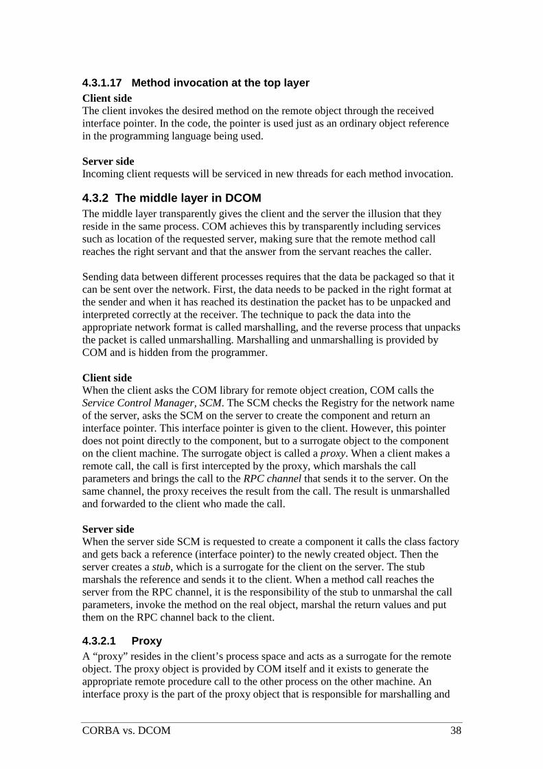
CORBA vs. DCOM 38
4.3.1.17 Method invocation at the top layer Client side The client invokes the desired method on the remote object through the received interface pointer. In the code, the pointer is used just as an ordinary object reference in the programming language being used. Server side Incoming client requests will be serviced in new threads for each method invocation.
4.3.2 The middle layer in DCOM The middle layer transparently gives the client and the server the illusion that they reside in the same process. COM achieves this by transparently including services such as location of the requested server, making sure that the remote method call reaches the right servant and that the answer from the servant reaches the caller. Sending data between different processes requires that the data be packaged so that it can be sent over the network. First, the data needs to be packed in the right format at the sender and when it has reached its destination the packet has to be unpacked and interpreted correctly at the receiver. The technique to pack the data into the appropriate network format is called marshalling, and the reverse process that unpacks the packet is called unmarshalling. Marshalling and unmarshalling is provided by COM and is hidden from the programmer. Client side When the client asks the COM library for remote object creation, COM calls the Service Control Manager, SCM. The SCM checks the Registry for the network name of the server, asks the SCM on the server to create the component and return an interface pointer. This interface pointer is given to the client. However, this pointer does not point directly to the component, but to a surrogate object to the component on the client machine. The surrogate object is called a proxy. When a client makes a remote call, the call is first intercepted by the proxy, which marshals the call parameters and brings the call to the RPC channel that sends it to the server. On the same channel, the proxy receives the result from the call. The result is unmarshalled and forwarded to the client who made the call. Server side When the server side SCM is requested to create a component it calls the class factory and gets back a reference (interface pointer) to the newly created object. Then the server creates a stub, which is a surrogate for the client on the server. The stub marshals the reference and sends it to the client. When a method call reaches the server from the RPC channel, it is the responsibility of the stub to unmarshal the call parameters, invoke the method on the real object, marshal the return values and put them on the RPC channel back to the client.
4.3.2.1 Proxy A “proxy” resides in the client’s process space and acts as a surrogate for the remote object. The proxy object is provided by COM itself and it exists to generate the appropriate remote procedure call to the other process on the other machine. An interface proxy is the part of the proxy object that is responsible for marshalling and
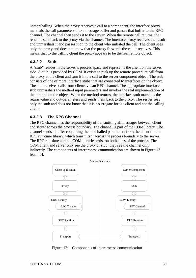
CORBA vs. DCOM 39
unmarshalling. When the proxy receives a call to a component, the interface proxy marshals the call parameters into a message buffer and passes that buffer to the RPC channel. The channel then sends it to the server. When the remote call returns, the result is sent back to the proxy via the channel. The interface proxy receives the result and unmarshals it and passes it on to the client who initiated the call. The client sees only the proxy and does not know that the proxy forwards the call it receives. This means that to the calling client the proxy appears to be the real remote object.
4.3.2.2 Stub A “stub” resides in the server’s process space and represents the client on the server side. A stub is provided by COM. It exists to pick up the remote procedure call from the proxy at the client and turn it into a call to the server component object. The stub consists of one of more interface stubs that are connected to interfaces on the object. The stub receives calls from clients via an RPC channel. The appropriate interface stub unmarshals the method input parameters and invokes the real implementation of the method on the object. When the method returns, the interface stub marshals the return value and out-parameters and sends them back to the proxy. The server sees only the stub and does not know that it is a surrogate for the client and not the calling client.
4.3.2.3 The RPC Channel The RPC channel has the responsibility of transmitting all messages between client and server across the process boundary. The channel is part of the COM library. The channel sends a buffer containing the marshalled parameters from the client to the RPC run-time library, which transmits it across the process boundary to the server. The RPC run-time and the COM libraries exist on both sides of the process. The COM client and server only see the proxy or stub; they see the channel only indirectly. The components of interprocess communication are shown in Figure 12 from [5].
Client application
Proxy
Transport
RPC Runtime
RPC Channel
COM Library
Server Component
Stub
Transport
RPC Runtime
RPC Channel
COM Library
Process Boundary
Figure 12: Components of interprocess communication

CORBA vs. DCOM 40
4.3.2.4 Service Control Manager (SCM) The responsibility of the Service Control Manager (SCM) is to perform remote object activation, which includes locating servant implementations and activating the servers where the servants reside. When a client asks for creation of a component or a client asks for a class factory, the SCM connects the appropriate server and makes sure that it is ready to receive client requests. Developers do not interact with the SCM directly, it is only the COM library that uses the SCM when asked to create an object or locate a class factory. The following is what happens in detail when a client calls a COM library function to create a remote object. First, the COM library contacts the SCM on the same computer. The SCM checks the Registry to find out on which server to find the requested component. The SCM on the client side contacts the SCM on the remote server machine. The remote SCM collaborates with the remote computers COM library to instantiate an object and return an interface pointer to the client. In Figure 13, it is shown how the SCMs work when a client requests creation of a remote object. Each host machine that supports COM has its own local SCM. The SCM is used only to activate the object and bind the initial interface pointer. After that the SCM is no longer involved in any client-server interaction.
Client Server
Create and activate server!
DCOMClient Application
COM Library
Create Instance!
SCM
Locate and activate server!
COM ComponentService
COM Library
SCM
Create Instance!
Activate component!
Figure 13: The SCM contacts the server side SCM to create a remote object.
4.3.2.5 Object activation at the middle layer 1. When the COM library receives the call to create a remote object instance it
forwards the call to the SCM. 2. The SCM checks if it has a class factory registered for the requested CLSID. If
the class factory is not already registered, the SCM checks the Registry to find information about the location of the server for the CLSID and starts it.
3. The server registers its class factory in a table. In this table, the server-side SCM finds the wanted class factory interface pointer and invokes a method to create an instance of it.

CORBA vs. DCOM 41
4. When the object is instantiated, COM creates an interface stub for it, marshals the interface pointer and sends it to the client.
5. At the client-side, COM creates an object proxy for the server object instance. The object proxy unmarshals the pointer and creates an interface proxy. The interface proxy is associated with the RPC channel to the stub.
6. Finally, a pointer to the interface proxy is returned to the client. Via this pointer the client can invoke methods on the remote object.
4.3.2.6 Method invocation at the middle layer 1. The client’s call to a remote method is first sent to the interface proxy, which
marshals the input parameters and forwards the call onto the RPC channel. 2. The RPC channel transports the call to the interface stub. 3. The interface stub unmarshals the parameters and invokes the method on the
real object instance. When the method returns, the interface stub marshals the values to be returned.
4. The RPC channel transports the result back to the interface proxy. The interface proxy unmarshals the result and forwards them to the client as the answer to the client’s call.
4.3.3 The bottom layer in DCOM The bottom layer consists of the wire protocol which ships the marshaled messages between the proxy and stub. The protocol is called Object PRC, ORPC. An object reference, OBJREF, is used to represent an object. A client has an OBJREF to the component it uses. The OBJREF contains two identifiers, one interface pointer identifier, IPID, and one object exporter identifier, OXID. The IPID is used within a server to find the object that is called. The OXID is used to find a connection to the server where that object resides. A service called the OXID Resolver knows how to map the OXID to the remote object’s server. The OXID Resolver also is involved in distributed garbage collection via reference counting that counts how many clients hold a reference to a component.
4.3.3.1 DCE RPC / ORPC DCOM is considered a high-level network protocol since it is layered upon several other protocols. The DCOM wire protocol is based on the Open Software Foundation (OSF) Distributed Computing Environment (DCE) RPC. DCOM is not really an independent protocol layered on top of RPC, but has extended the RPC layer. Therefore, the DCOM network protocol is often called Object RPC, ORPC, to show the close relationship with RPC. DCOM uses the marshalling of simple data types specified by the OSF DCE RPC, but this standard has been extended to also support marshalling of interface pointers. In Figure 14 from [11], the authors draw the OSI model including the DCOM/RPC. Many different protocols can be substituted below the DCOM/RPC layer.

CORBA vs. DCOM 42
Data Link Ethernet Driver
Physical Ethernet
Network Internet protocol
Transport User Datagram Protocol
Session Winsock Driver
Presentation
Application DCOM/RPC
Figure 14: An example of the ORPC in the OSI model
4.3.3.2 Reference counting and pinging A server has to have some means to find out if a remote client, that has a connection to one of its object instances, terminates abnormally and cannot signal when it has finished using the servant. This is achieved by pinging. The first time an interface pointer to a remote object is obtained, the client adds the object to a ping set on the client computer. The client periodically sends a ping to each of the server machines in the ping set. When a server receives a ping from a client it draws the conclusion that the client is still working properly. If a server misses a certain number of pings from a client, it draws the conclusion that the client has terminated abnormally. Then the server releases the interface pointers to that client. This way a server performs garbage collection of remote object references. The part of a server that keeps track of the clients’ ping messages is the OXID Resolver. The pinging mechanism is an extension to RPC added by ORPC.
4.3.3.3 IPID, OXID and OBJREF A DCOM network remote procedure call contains a header with identifier information so that the call will reach its appropriate receiver. One of those identifiers is an interface pointer identifier, IPID. An IPID represents a particular interface on a particular object in a particular server. An IPID is however not globally unique and it does not by itself give the binding information necessary to reach a remote component and carry out an invocation. Therefore, an object exporter identifier, OXID, is used to represent connection information. The OXID identifies the RPC string binding information needed to connect to the interface targeted by the IPID. The string bindings contain the network address of the server where the component runs and information about the underlying network protocol that should be used. When making a call, the client must first translate the OXID into an object reference, i.e. the string bindings, that the RPC channel understands. Every computer has an OXID Resolver service that keeps track of all OXIDs on the computer. An OBJREF is the data type used to represent a reference to an object. The OXID and IPID of an interface are put into an OBJREF and added to the message to the client when the interface pointer is sent. With the information in the OBJREF the client knows how to contact the server.

CORBA vs. DCOM 43
4.3.3.4 OXID Resolver The OXID Resolver is a service that performs two main services.
1. It stores the string bindings necessary to connect to OXIDs of objects that have been exchanged with other machines. The computer is either a client or the server to the objects for which it stores the bindings. The Resolver services a client by returning the RPC binding to an OXID.
2. It receives pings from remote clients and keeps track of the pings so it knows how long to keep its own objects running.
To do the mapping between the OXID and a binding, the OXID Resolver stores the mapping information in a local table. When a client asks it to resolve an OXID the OXID Resolver first checks its table for the OXID. If it is found, the binding can be returned immediately to the client. If it is not found, the OXID Resolver contacts the OXID Resolver on the server side, which resolves the OXID and returns the binding to the asking Resolver.
4.3.3.5 Object activation at the bottom layer 1. After receiving the request from COM to create an instance of a remote object,
the SCM checks the Registry to find out on which other machine it can find the object. When it knows what other machine to call, it contacts the SCM on that computer.
2. The server-side SCM starts the server and assigns an OXID to it. Clients that want to reach the server need to know the RPC binding to it. To be able to translate from OXIDs to RPC bindings when a client asks, the OXID Resolver registers the mapping between the server’s OXID and its RPC binding.
3. An object reference, OBJREF, is created as a representation of the interface pointer. The OBJREF contains the IPID, the OXID and the address of the server-side OXID Resolver.
4. When the stub marshals the interface pointer to the newly created object the OBJREF is added to the message that is sent to the client.
5. The interface pointer is sent to the client from the server-side SCM to the client-side SCM. At the client, the object proxy extracts the OXID and addresses of OXID Resolvers from the OBJREF. Since the COM runtime has not seen this OXID before the proxy calls the local OXID Resolver.
6. The client’s OXID Resolver checks if it has a stored mapping for the OXID. If not, it calls the server-side OXID Resolver, which returns the registered RPC binding.
7. The client’s Resolver stores the mapping from the OXID to the RPC binding and returns the RPC binding to the proxy. With this binding the proxy can connect itself to the RPC channel that is connected to the server.
4.3.3.6 Method invocation at the bottom layer 1. When a client calls a remote object, the proxy receives the call and marshals
the parameters. 2. The RPC channel transports the call to the OXID Resolver on the server with
help from the OXID-RPC channel binding. 3. Based on the IPID in the RPC header the server targets the appropriate
interface stub and forwards the call to it. 4. The interface stub invokes the method, waits for it to return, marshals the
result and returns it to the proxy.

CORBA vs. DCOM 44
4.4 Overview of COM+ COM+ is the latest version of the Microsoft’s Component Object Model, as described in [26]. COM+ is integrated into Windows 2000 and it consists of three parts; Microsoft’s basic component model, its distribution capability and the component runtime environment. COM+ is the combination of Microsoft Transaction Server (MTS, the original component runtime environment), COM (the original component model) and DCOM (the original distribution technology), plus some new services. The distribution architecture (DCOM) has not changed since COM/DCOM and this part of COM+ is still often referred to as DCOM. The terms from COM are still used in COM+. Since it is demanded that COM+ is backwards compatible with COM, a COM component can be run in COM+ and therefore the terms COM component and COM+ component are sometimes mixed. COM+ is designed to provide a rich runtime environment to hide troublesome issues from the developer. Before COM+, it was more complicated to create a COM object. Then the developer had to supply functionality other than the business logic, for instance special code to register the class or manage object lifetime. But with COM+ the developer merely describes the characteristics of the class and the COM+ runtime takes care of much of the rest.

CORBA vs. DCOM 45
Part 2: CORBA and DCOM/COM+ side by side

CORBA vs. DCOM 46
5 CORBA and DCOM/COM+ side by side
5.1 Object model The object model describes object concepts and terminology that is of interest for clients. This includes object creation and identity, requests and operations. The following features are compared in the object model:
• Separation of interface and implementation • The Interface Definition Languages, IDL and MIDL • Description of an object • Object reference • Dynamic Invocation
5.1.1 CORBA Separation of interface and implementation In CORBA the interface is the collection of methods available for client invocation. The interface serves as a contract between the client and the server. All access to the object is done through its interface, never directly through the object implementation. An object’s type is the interface’s type. There is a one-to-one correspondence between an interface and a CORBA object. IDL The OMG IDL allows multiple inheritance, meaning that an object may support multiple interface types. An object has support for its own interface type, but this interface may inherit from other interfaces, which gives the object support for multiple interfaces. The OMG IDL defines a common set of data types accessible to all target languages. When programming in CORBA, the IDL is usually specified for each CORBA object, still every object requires an interface. There are however tools that hides the IDL, for example Caffeine. Caffeine from Netscape and Inprise is a pure Java solution where the IDL is hidden from the programmer. Description of an object A CORBA object is a blob of intelligence that can live anywhere on a network. It is packaged as a binary component that can be accessed by clients via method invocations. The object’s operations, input/output parameters and return values are defined in its interface using OMG IDL. Object reference The CORBA object reference identifies an object instance uniquely in a network. According to the CORBA specification [7], it is up to the ORB vendor how to implement the object reference. In Visibroker, the object reference consists of an array of bytes, which uniquely identifies an object instance. In a POA-based ORB the object reference is created at the server side, since it is server related. The POA assigns the reference at object creation and the persistent services use it to save an object’s state so that it can be reactivated at a later time. As long as the CORBA object is “alive”, the client can use the object reference to invoke its methods. The object reference becomes useless once the CORBA object has been destroyed.

CORBA vs. DCOM 47
Dynamic invocation CORBA supports dynamic invocation through the Dynamic Invocation Interface. It uses the interface repository to look up interfaces not encountered at compile time. Once it has found the interface, the client constructs a request object that specifies all the necessary information needed to invoke the call. This request object is created at compile time when using static invocation. When the request object has been created, the invocation method is called on it to carry out the request.
5.1.2 DCOM Separation of interface and implementation In COM, an object can support multiple interfaces and a COM class is an implementation of one or more interfaces. (A COM class is also called a component object class.) A client never has direct access to the COM object. Instead, clients always access the object through the interfaces that the object supports, and only those interfaces. IDL Originally, programmers had to write COM IDL files and they can still do so if they want to. The IDL file was compiled to create a type library, which is a machine-readable description of the object and its interface. Today, there are many development tools that generate the type library directly from the object code and there is no need for an IDL file. In fact, there is no need for the programmer to know how to write an IDL at all, and fewer and fewer do write IDL files. An IDL file is rather complicated to write and the fact that there is no defined set of data types is a problem. For instance, it is possible to write an IDL file that defines data types that are accessible to C and C++, but not accessible to Visual Basic and Java. The COM IDL is also often called MIDL, Microsoft IDL. What is an object? The term object means an instance of a COM class. A COM object is also often called a component. A COM class is identified by its CLSID, through which a client can activate an object. The object physically resides somewhere in a network on a server. All servers expose their object’s services through interfaces. Object reference Clients access COM objects through a reference called interface pointer. If the client knows the CLSID, it can get an interface pointer to one of the object’s interfaces, and using that pointer the client can invoke the operations in that interface. Using this interface pointer the client may also ask the object for pointers to its other interfaces. In DCOM there are no object references in the sense that a CLSID/ProgID uniquely identifies an instance of an object in a network, because the CLSID/ProgID identifies a class but not a certain object instance of that class. To give a specific instance of an object a particular name that would allow a client to reconnect to that same object instance with the same state (not just another object of the same class) at a later time, an object called Moniker has to be used. Monikers know how to handle name information and relocate the specific object to which that name refers.

CORBA vs. DCOM 48
Dynamic invocation A component may have more than one interface. If a client possesses an interface pointer it can query the component to find out about its other interfaces. This provides a late-bound mechanism to access and retrieve information about an object’s methods and properties. Dynamic invocation in COM means the ability of a client to discover and invoke an object’s methods at run time instead of at compile time. The component’s other interfaces may very well offer other services to clients than the first interface the client has a reference to. A client that wants to do dynamic invocation on interfaces that are discovered at runtime uses a special dynamic invocation COM interface. The object must implement this interface, which can be fairly complicated.
5.2 Services
5.2.1 CORBA The CORBA services provide a necessary part of commonly needed functionality used when designing distributed applications. They are accessed via middleware APIs and are packaged with IDL-specified interfaces. OMG has published standards for sixteen object services: Collection Service A CORBA service that supports grouping of objects and support operations for the manipulation of the objects as a group. Common collection types are queues, sets, bags etc. Concurrency Service A CORBA service that controls the concurrent access by transactions and threads to a shared object. The service makes sure to that the consistency of the object is preserved. Event Service A CORBA service that allows objects to dynamically register or unregister their interest in notification of specific events. Externalisation Service A CORBA service that defines protocols and conventions for externalising and internalising objects. This means that it provides a standard way for getting data into and out of a component using a stream-like mechanism. Licensing Service A CORBA service that provides technical licensing tools to control the use and access of developed products. Life Cycle Service A CORBA service that provides services for operations for creating, deleting, copying and moving objects. Naming Service A CORBA service that allows objects to locate other objects by name.

CORBA vs. DCOM 49
Notification Service A CORBA service that extends the already existing OMG Event Service. Persistent State Service A CORBA service that provides ways for storing objects persistently on a number of different storage servers. Property Service A CORBA service that provides operations to dynamically associate named values with objects outside the static IDL-type system. Query Service A CORBA service that provides query operations on collections of objects. The queries can be specified using SQL and other object query languages. Relationship Service A CORBA service that provides a way to create dynamic associations between objects. Relationships of arbitrary degree can be defined. Security Service A CORBA service that provides security functions for distributed objects. It supports identification and authentication, authorization and access control, confidentiality and non-repudiation to mention some. Time Service A CORBA service that provides synchronization of time in a distributed system. It also provides operations for defining and managing time-triggered events. Trading Object Service A CORBA service that provides the offering and the discovery of instances of services. It allows objects to publicize their services and bid for jobs. Transaction Service A CORBA service that provides two-phase commits coordination for transactions. A recoverable object can participate in a flat or nested transaction. As mentioned above, there are several services among which there are some that are considered as “core services” or essential services. These services are:
• Transaction service • Security service • Event and notification service • Naming service
The main features of the OMG specifications for these services are described below.
5.2.1.1 Transaction service When using CORBA, transactions can range over multiple distributed objects and multiple data resources. The transaction service adds support for transactions for objects living on the CORBA ORB. Since transactions are an essential part of distributed systems, almost all of the leading CORBA vendors have added an

CORBA vs. DCOM 50
implementation to their CORBA product suites. Inprise has its own implementation called Integrated Transaction Service later. The Figure 156 below shows the major components and interfaces defined by the Transaction Service.
Current
ControlCoordinator
RecoveryCoordinator
transactioncontext
transactioncontext
transactioncontext
Transaction Service
transaction originator recoverable server
TransactionFactoryControl
Terminator Current
Resource
(associated with thread) (associated with thread)
(transmitted with request)
Figure 15: Major components and interfaces of the Transaction Service.
Using a TransactionFactory, the transaction originator creates a Control object that provides access to a Terminator and a Coordinator. The Terminator is used to commit or rollback transactions while the Coordinator is made available to recoverable servers. A recoverable server is a collection of objects at least of which one is recoverable. A recoverable object is an object that committing and rolling back a transaction affects its data. The Coordinator can be used to:
• Determine the relationship between two transactions. • Recoverable objects can register a resource object as a participant in a
transaction. The resource object is used to represent the recoverable objects participation in the transaction.
The RecoveryCoordinator is used by a resource to determine the outcome of a transaction and to coordinate the recovery process. To simplify programming, the transaction runtime system provides a Current object instance that is associated with the current thread of control. These instances do not have to be created by the user. They provide an implicit per-thread transaction context. Within a transactional application there are two ways of creating and managing a contexts:
1. Direct context management. The transaction context is manipulated directly via a Control object instance.
2. Indirect context management. The application uses a Current instance to manage the transaction context.
The transaction service provides two different approaches for propagating contexts:
1. Explicit context management. When invoking transaction objects, a Control object reference is passed as a parameter.
6 Page 26 in [9]

CORBA vs. DCOM 51
2. Implicit context management. The context maintained in the Current instance is passed as an implicit argument. To be able to receive the implicit argument, CORBA objects must inherit from the TransactionalObject. The implicit approach is easier to program because the ORB takes care of the propagation of the transaction context.
As already stated, the easiest approach is to use indirect context management and implicit context management which both relies on the use of the provided Current instance. To participate in transactions, CORBA objects need to inherit from the TransactionalObject and use the provided Current object instance to begin, commit and roll back transactions.
5.2.1.2 Security service In distributed systems there are several security issues that must be considered when building large applications. The following points are basic requirements that must be met by a distributed system according to [22].
• User authentication; which means to determine the true identity of a client. The most common way to do authentication is to use login names and secret passwords.
• Data integrity; as the “wire” between the client and the server becomes longer the risk that someone unauthorized alters the data being transported increases. Usually, data integrity is guaranteed by the low-level network transport that computes a checksum on the data being sent. If the data is changed during transport, the receiver detects this when computing the checksum and the data has to be retransmitted.
• Privacy, which means that in some cases the data that is being sent has to be encrypted, so that nobody else but the true receiver knows how to decrypt and view the data.
• User authorization, before the server can do what the client requests, the server has to make sure that the client is authorized to perform that task. It is important both to prevent unauthorized users from being serviced by the server and to make sure that authorized users get their requests serviced. This often requires a large amount of administration to work properly.
Of course, which mechanisms that are used to secure an application depends on the requirements of that application. Security and SSL As mentioned earlier in Section about the bottom layer for CORBA, the primary communication protocol used by CORBA ORBs is the Inter-ORB Protocol (IIOP). Because IIOP has no inherited support for a security mechanism, several vendors has developed security packages for their CORBA ORBs built upon the Security Sockets Layer (SSL). SSL uses RSA public key cryptography to realize secure connections. The SSL exists as a separate secure layer between IIOP and TCP/IP. The layer is organized as Figure 167 below illustrates.
7 Page 174 in [22]

CORBA vs. DCOM 52
CORBA Client
ORB
IIOP
SSL
TCP/IP TCP/IP
SSL
IIOP
ORB
CORBA Server
Figure 16: The SSL used with CORBA
CORBA servers and clients uses the SSL for the following reasons:
• Authentication. Using SSL, the server and client can validate each other. This is possible through the use of a SSL handshake protocol that uses public and private keys. Applications rather than individual users mostly use this authentication.
• Data integrity. By using a message authentication code (MAC) with each transmitted message, SSL ensures against data tampering. The MAC is a computed checksum that is used to validate the transmitted data.
• Privacy. Using the public and private keys, another key known as a secret is exchanged. This is used to encrypt and decrypt the data that is passed across the SSL connection.
CORBA/SSL is not enough for user authorization, however it provides a lightweight solution for ensuring authentication, data integrity and privacy. For an environment where authorization, authentication, data integrity and privacy are required, CORBA vendors provide implementations of the CORBA Security Service. The specification of the CORBA Security Service is a comprehensive specification given by its 400 pages. It took two years of effort to approve it and the first implementation was available two years later. This can be explained by the complex nature of the specification, which mainly addresses security issues in large enterprise systems. The security specification describes the following security key features:
• Identification and authentication. To verify that a user or object (principal) are who they claim to be.
• Authorization and access control. Deciding whether a principal can access an object.
• Security auditing. To audit activity within a security enabled ORB. This recording of security events helps to detect actual or attempted security violations.
• Security of communication. To have secure communication between objects. • Non-repudiation. To hold client and servers accountable for their actions.
Evidence about a claimed event can be checked to provide proof of the action. It can also be stored to resolve the occurrence or non-occurrence of the event or action.
• Administration. To administrate security information.

CORBA vs. DCOM 53
• Interoperability. To allow interoperability across distinct security-enabled ORBs. This is done through the use of the Secure Inter-ORB Protocol (SECIOP).
5.2.1.3 Event and notification service When things happen in a distributed enterprise system, there are many parts that need to find out. There are many situations where so-called CORBA events are useful, for example in the telecommunications industry where it is used for network administration and maintenance. The notification service is a development of the older event service, which lacked the quality of service aspect. In 1993, when the event service specification was first developed, many details were left to the implementer. This gave different implementations of the event service, which supported different quality of service. The quality of service introduces requirements to support different application needs:
• Reliability requirements from “at-most-once” semantics to guaranteed “exactly-once”.
• Availability requirements. • Throughput requirements. • Performance requirements. • Scalability requirements.
The programming model in CORBA is inherently synchronous. To address asynchronous issues, the CORBA Event Service and the CORBA Notification Service were formed. Instead of providing asynchronous invocation of methods in CORBA, the services rely on intermediate CORBA objects called event channels. These are described in later in The Visibroker Event Service. The notification service is not a part of the Visibroker base services; it is available as an add-on. The foundation of the notification service is the event service, which is described here.
5.2.1.4 Naming service An important thing in distributed systems is “sharing”. To share information and resources is one of the corner stones in distributed systems. The naming service is the component that makes sharing possible. The naming service provides the ability to associate one or several logical names with an object reference and to obtain that reference using the assigned logical names. When a client connects to an ORB it uses the naming service to get references to other objects on the ORB. According to [8], a name-to-object association is called a name binding. A name binding is always defined relative to a naming context. A naming context is an object that contains a set of name bindings in which each name is unique. An object can have different names and exist in one or several contexts at the same time. To resolve a name is to find an object given a name in a context. To bind a name is to create a name binding in a given context. A naming context can also be bound to a name in a naming context, creating a naming graph.

CORBA vs. DCOM 54
5.2.1.5 Visibroker services The ORB used for the description of the layers and for the implementation of the tests, the Visigenic Visibroker, does not support all the above listed services. There is however a complete range of CORBA Services from Prism Technologies, called OpenFusion®. OpenFusion adds support for the following services in Visibroker:
• OpenFusion Trading Service • OpenFusion Notification Service • OpenFusion LifeCycle Service • OpenFusion Property Service • OpenFusion Collection Service • OpenFusion Concurrency Service • OpenFusion Relationship Service • OpenFusion Time Service
The following services are part of the Visibroker 4.1 distribution:
• Smart Agent • Location Service • Naming Service • Event Service • Security Service • Integrated Transaction Service (ITS)
Integrated Transaction Service (ITS) The Integrated Transaction Service provides support for distributed transactional CORBA applications. It is a fully CORBA-compliant transaction service, which implements the CORBA Transaction Service. There are two types of transactions where ITS supports the flat transaction model, the nested transaction model is not supported. A feature of flat transactions is the all-or-nothing property, i.e. either all steps of a transaction must complete, or none of the steps must complete. The flat transactions can use a one-phase or two-phase commit protocol. Implemented on top of the ORB, ITS provides a set of services: transaction service, recovery and logging, integration of databases and administration facilities according to [30]. ITS currently supports the following components:
• ITS Transaction Service • ITS Database Integration • ITS Administrator
ITS Transaction Service The ITS Transaction Service manages transactions. The service conforms to the OMG CORBA Transaction Service. It is provided as a library and an executable. Several instances of ITS Transaction Service can be used in the network to load balance transactions. ITS Database Integration ITS Database Integration supports integration of transactional applications with databases. Support for JDBC and an ITS-enabled connection to a database are some of the features included.

CORBA vs. DCOM 55
ITS Administrator The ITS Administrator is a graphical tool used for monitoring transactions. Visibroker SSL pack The Security Service is an option to Inprise’s Visibroker ORB, which provides an introductory level of security. By using the VisiBroker Secure Sockets Layer (SSL) pack, features as authentication and encryption can be added to distributed applications. The service is based on industry standards such as RSA’s BSAFE Crypto Libraries and Consensus’ SSL Plus. Digital certificates Visibroker SSL uses digital certificates, which is a standard for authentication and ensuring message integrity. The Digital certificates provide detail about client objects and are issued by a certificate authority or by a certificate server. Quality of Protection The level of security can be altered at runtime to achieve better performance. Authentication The SSL pack provides client authentication to enable the server to determine that a particular client is authorized for using a specific server object. Deployment and administration VisiBroker SSL Pack can be used with Java applets, Java applications, or C++ applications. Objects written in these two languages can be secured and can interoperate with each other. If Java applets are used, there is no need for client-side installation as they can use IIOP over HTTPS, an SSL facility built into recent versions of Netscape and Microsoft browsers. With Java applets, no digital certificate management is required as it is handled entirely by the browser itself. The Event Service The Event Service provides a supplier-consumer communication model for objects communicating with each other. Figure 178 shows a supplier-consumer communication model. With this model, multiple supplier objects may send data asynchronously to multiple consumer objects through an event channel. The model allows an object to tell another object about a change in its own state. .
8 Page 214 in [29]

CORBA vs. DCOM 56
Figure 17: Supplier-consumer communication model.
If one message is sent from the two suppliers, both consumers will receive two messages each. A total of four messages are being handled in the event channel. The suppliers send data into the channel and the consumers pull data out from the channel. The Visibroker Event service conforms to the OMG Event service with the following exceptions:
• The event service only supports generic events. There is currently no support for typed events.
• The event service offers no confirmation of the delivery of data to the event channel or to consumer applications. TCP/IP is used as communication protocol. This provides reliable delivery of data, however it does not guarantee that all data sent is actually processed by the receiver.
The event service provides both a pull and push model for suppliers and consumers. With the push model suppliers control the flow of data by pushing it to consumers. An example of the push model is a supplier that monitors available free space on disk and notifies interested consumers when the disk is filling up. In the pull model, consumers control the flow of data by pulling data from the suppliers. An example of a pull consumer is one or more network monitors that poll a network router for statistics. The Smart Agent VisiBroker’s Smart Agent is a dynamic, distributed directory service that provides facilities used by both clients and object implementations. At least one Smart Agent has to be started within a local network. When a client program calls bind() on an object, the Smart Agent is automatically contacted to help establish connection between the client and the object implementation. The cooperation with the Smart Agent is completely invisible to the client. Smart Agents can cooperate when they are situated in different local networks. A Smart Agent can find remote Smart Agents when it is given the IP addresses of the other. When more than one Smart Agent is started in a local network they communicate to find the requested objects. If one Smart Agent terminates all implementations registered with that Smart Agent immediately discovers this and register with another Smart Agent.
Supplier object 1
Supplier object 2
Consumer object 2
Consumer object 1
Eve
nt C
hann
el
data
data data
data

CORBA vs. DCOM 57
VisiBroker locates a Smart Agent by sending a broadcast message, and the first Smart Agent that responds is the one that is used. A point-to-point UDP connection is used for sending registration and look-up requests to the Smart Agent. The protocol UDP is used because it reduces the demand for network resources. Client programs register with the Smart Agent in order to find object implementations. The ORB contacts the Smart Agent to locate an object server that is offering the requested interface. Every two minutes, the Smart Agent sends an “Are You Alive” message (also called heartbeat message) to its clients to control that they are still connected. If the client does not answer it is assumed that it has terminated. The Location Service The Location Service is an extension to the CORBA specification, which provides facilities for locating object instances based on particular attributes. It communicates with a Smart Agent, which has a catalogue containing the instances it knows about. When the Location Service queries the Smart Agent, it forwards the query to the other Smart Agents, collects all the replies from the other agents and returns it to the Location Service. The Location Service components The Location Service is reached through a specific interface. The methods for this interface can be divided into two groups. The first group queries the Smart Agent for data describing instances and the second group register and unregister triggers. The Location Service Agent The Location Service Agent is a collection of methods that enable discovery of objects on a network of Smart Agents. The result returned by a query can be an object reference or a more complete interface description containing the object reference, the instances interface name, instance name, host name, port number and information about its state. Trigger A trigger is a callback mechanism that allows clients to be notified when the availability of an instance changes. It is typically used to recover after the connection to an object has been lost. The Naming Service The Naming Service allows the programmer to associate one or several logical names with an object reference and store them in a namespace. Another feature is the ability to allow clients to obtain an object reference by using the object’s logical name. The Figure 189 below shows the way a naming context is used when resolving, binding and using an object reference.
9 Page 190 in [29]

CORBA vs. DCOM 58
Figure 18: Binding, resolving, and using an object name from a naming context
within a namespace. The differences between the naming service and the Smart Agent are:
• The Naming Service uses a hierarchical namespace while the Smart Agent uses a flat one.
• To change the interface name requires recompiling of an application when using the Smart Agent. When using the Naming Service, object implementations can bind logical names to its objects at runtime.
• An object has one interface with one name when using the Smart Agent. The Naming Service allows binding of more than one logical name to a single object.
5.2.2 COM+ The COM+ services described here are the services that are considered as essential to a distributed system. Microsoft offers a lot more specialized features to COM+, but they cannot all be described here. Distributed Transaction Coordinator (DTC) The Microsoft Distributed Transaction Coordinator (DTC) provides a transaction manager for each computer that manages transactions as specified in [2]. The application programmer knows that transactions either succeed or fail; this feature is provided by the DTC. The DTC is responsible for managing transaction contexts and coordinating two-phase commits, i.e. DTC ensures that everything involved with a transaction either commits or rolls back. On Windows 2000, the DTC is tightly integrated with COM+. COM+ does not support nested transactions. Applications call the transaction manager when they want to begin a transaction. First, a transaction object that represents the transaction is created. After that the application
Object implementation
Client application
Namespace 1. bind(name, obj_ref)
2. resolve(name)
3. resolve returns an object reference
4. invoke methods on object

CORBA vs. DCOM 59
calls the resource managers, such as relational databases, to do the work of the transaction. The transaction object is included in the requests to the resource managers. This way all the work is performed on behalf of the same transaction object until the transaction is ended. The transaction manager keeps track of each of the resource managers taking part in the transaction. When a transaction ends, the DTC coordinates the different resource managers and chooses whether to abort or commit the transaction according to the two-phase commit protocol. Even if multiple databases from different vendors are used in a transaction, DTC can coordinate their work. These databases all know how to cooperate with the DTC and it knows how to coordinate their activity with each other. When a transaction updates data on more than one networked computer, it is called a distributed transaction. For distributed transactions, each computer has a local transaction manager. The local transaction manager tracks incoming and outgoing transactions on that computer. Among all transaction managers, one is chosen to be the coordinator for the transaction and it is called the root or coordinating TM. When deciding whether to abort or commit a transaction distributed among several computers, the root transaction manager makes its decision to abort or commit by applying the two-phase commit protocol among all participating transaction managers. In a traditional transaction processing application, the programmer controlled transaction boundaries with explicit instructions to begin and end the transaction. With COM+, the programmer may let the COM+ runtime environment decide and notify DTC when a transaction begins and ends. The programmer does not have to write any explicit code to start or end a transaction. In this case COM+ manages transaction boundaries automatically, based on a declarative attribute that is set for each component. This attribute is set in the Component Services administrative tool in Windows 2000. But each component that participates in a transaction should programmatically tell the DTC that it has completed its work successfully or not by calling a function that tells the DTC whether the component wants to abort or commit. Security The important basic requirements that must be met by a distributed system are defined in the Section 5.2.1.2. COM+ provides several security choices for an application as specified in [24]. Security settings can be configured both in the code by a programmer (programmatically) and declarative (administratively). Some security settings make it possible to not have to include any security functionality inside a component, but to leave the security details to COM+ to handle. The basic security features of COM+ are:
• Authentication services • Declarative/Programmatic role-based security • Impersonation/delegation
Authentication service for COM+ applications is turned on and configured administratively and works transparently to the applications. The Component Services administrative tool can be used to specify the authentication level. Setting different authentication levels tell COM+ how it should verify the identity of its clients and thus give different degrees of security. The lowest degree is no authentication at all, and the highest degree is demanding authentication and encryption of every packet

CORBA vs. DCOM 60
sent. COM+ handles negotiation between the client’s authentication level and the server’s authentication level. This means that a component protect itself by demanding authentication, which will be reflected in the negotiations with a client that does not demand any security. Role-based security gives the possibility to deal with user authorization. Each user is allotted a role, and each role has its authorization settings. This way, many users are logically grouped together sharing the same role. By defining the settings for a certain role, the authorization settings is defined for the whole group of users at the same time and there is no need to make any individual settings for all the users. The roles make it easier for an administrator to control which users may access any resource. The Component Services administrative tool can be used to configure role-based security administratively. The settings for a group can be set at different levels; at the method level, as well as at the component and interface level. If role-based security is used there may not be any need to bother the component programmer with security details. It may be enough to let COM+ decide which users are authorized to use the component by checking the settings of the user’s group. If not, role-based security can be used as a supporting platform and a more fine grain security policy can be built into the component programmatically. For instance, the component can check role membership to determine which parts of the code to execute. Impersonation means that the servant represents the client by using the client’s identity instead of its own, when accessing resources on behalf of the client. Using impersonation insures that the servant can do exactly what the client can do and only what the client is allowed to do. Impersonation is configured administratively and must also be supported programmatically in the component. Delegation means impersonation of clients over the network. In this case both the client and the server need to be properly configured. The configuration settings give the domain administrators a high control over delegation. Asynchronous/Queued Components Queued Components is based on Microsoft Message Queuing Services, MSMQ, and provides an easy way to invoke and execute components asynchronously as described in [26]. An asynchronous component is a component that completes its work requests asynchronously with respect to the requesting client. With asynchronous components, method invocations can be stored and processed at future times. For instance, processing orders at night when system load is much lower. A queued component consists of:
• a Recorder • a Listener • a Player

CORBA vs. DCOM 61
A typical queued component scenario is the following. 1. The client calls a queued component recorder, which packages the call and
puts it in a queue. 2. The queued component’s listener fetches the message from the queue and
forwards it to the player. 3. The player invokes the method on the server component.
Events COM+ Events is a loosely coupled event, LCE, system as described in [26]. The event service allows component instances to be notified of events initiated by other instances. In contrast to a polling system where the interested part repeatedly polls the server, the event system notifies interested parties as soon as the wanted information becomes available. The components that are interested in being informed at certain events are called subscribers and the components that fire the events are called publishers. COM+ stores event information from different publishers in an event store. The subscribers look in this store to select and subscribe to any events they are interested in. Later, when an event occurs, the event system queries the store to find the subscribers and lets them know that the event has happened. Subscriptions are maintained outside of the publisher and subscriber in a connecting component called EventClass. This way, the programming model for the publisher and subscriber is simplified. The subscriber does not need to contain the logic for building subscriptions; it just calls the Event System to select an event to subscribe to. The publisher registers an event in the Event System by creating an EventClass object. When the publisher wants to fire an event it calls the appropriate method on its EventClass object and it is the responsibility of the Event System to forward the event to the subscribers. Figure 19 shows how a subscriber is notified when a publisher fires an event.
Figure 19: The scenario when a publisher fires an event
Naming Before the release of Windows 2000, the COM library used the Windows registry to provide directory services in COM as specified in [16]. When a client called an operation in the COM library with the name of the desired object as input parameter,
Publisher Subscriber
Event System
EventClass Object
Subscription Notify about event
Fire event

CORBA vs. DCOM 62
the COM library looked up the CLSID corresponding to the name in the registry. In the case of remote objects, the registry also contained the network name of the remote server machine. With this information, the remote object could be found. With the Windows 2000 operating system, COM+ added the concept of a central store for COM+ classes called Active Directory presented in [1]. The Active Directory is a directory service designed for distributed networking environments and facilitates the work of both administrators and programmers. Instead of having a name-CLSID-location-mapping directory on each computer, this information is stored in a central computer, which all other computers in the network know about. The COM libraries on all the computers in the network can retrieve location and activation information from the Active Directory. There is only one place where a new component has to be registered and then all computers in the net can find it. If a component’s settings have to be changed, these changes are made in the Active Directory and the changes will then be visible to all the COM libraries. The benefit is that the changes only have to be made on a single place instead of at the server and all the clients. The Registry can still be used as a naming directory exactly as before with the Windows 2000 operating system. In [16], another object instance naming mechanism is defined, which uses naming objects called monikers. The monikers contain the logic necessary to find a currently running instance of the object that they are naming. Monikers also have the ability to reinstantiate and initialise an object instance in case there is no running instance. The moniker object knows how to connect to the actual object instance and the client does not know how the moniker does this.
5.2.3 Summary Both CORBA and COM+ provide the essential services needed in a distributed system. CORBA’s services are well defined and different vendors have their implementations of (some of) the services. COM+ uses many of the tools and features of the Windows platform to provide services. These services are not all explicitly called COM+ services, but they can be used with COM+. Windows provides a lot of services to COM+ and all of them could not be presented here. This Section presented the essential services in both technologies.
5.3 Scalability A system’s scalability means how well a solution to some problem will work when the size of the problem increases, for instance how an application services a growing number of users. An application that scales well services an additional load with a linear increase in resource usage. Limits to scalability often depend on the application’s design. The question of scalability addresses the issues regarding how a system will use the resources that it own.
5.3.1 CORBA After the instantiation of an object the object reference to that instance is valid as long as the object instance is “alive” and not explicitly destroyed. This means that an object still is running although a client have not accessed it for a long time, which is a waste of computer resources. To utilise these wasted resources for better things the object need to be swapped out of the execution space. If the object has persistent state,
CORBA vs. DCOM 63
it also needs to be saved. Once the object is needed, it is swapped in. This swapping mechanism is provided by the POA. The memory management of object state is crucial for the scalability. A bad state management gives a bad resource utilization leading to a bad scalability, because of wasted computer resources. A good state management gives benefits:
• Easy recoverability after errors • Avoidance of single points of failure • Transactional behaviour • Dynamic configuration
These benefits require extra work from the programmer but they are necessary for a good scalability with enterprise-level computing. The notion of stateful objects in CORBA does not provide the ability to reuse instantiated objects, which can be done with stateless objects. The reuse of stateless objects is known as object pooling. As stated earlier, the quality of design has a big impact on the scalability of distributed systems. When designing distributed applications in CORBA, the CORBA services provide a necessary part of needed functionality. This means that the quality and range of CORBA services have a great influence on design and therefore the scalability. One way to control memory utilization is to control the memory management of objects via the POA. Here are two examples:
• Explicitly activate an object at server initialisation and keep state in memory until server termination. This stateful object could be deactivated when it is not used any longer, saving memory resources. This is useful for objects with “little state” that are called many times per second.
• Using servant managers.
5.3.2 COM+ One feature that COM+ provides is Just-In-Time (JIT) activation, which is specified in [18]. JIT activation means that COM+ will at times deactivate an instance of it while a client still holds an active reference to the object. If a client holds a reference to a servant that has not been used for a while, COM+ can decide to deactivate the object but keeping the connection between the client and the server. Later when the client calls the object, COM+ reactivates the object and services the request. The de-/reactivation is handled transparently by COM+. An object can signal to COM+ that it is ready to be deactivated by calling a COM+ API function. JIT activation is only applicable to stateless objects, since COM+ does not store the object state at deactivation. Making a component JIT activated is made administratively in the Component Services tool. The advantage of doing this is that you enable clients to hold references to objects for as long as they need them, without necessarily tying up server resources — such as memory — to do so. Also object pooling can be made by COM+ as described in [19]. A component is configured to be pooled administratively in the Component Services tool. The component administrator sets the component to be pooled and chooses how many

CORBA vs. DCOM 64
objects will be created and put into the pool from the start. All pool related work is then handled by COM+. JIT activation and object pooling can be combined and used simultaneously. By pooling objects that are being JIT-activated you can speed object reactivation for clients, while reusing whatever resources the objects might be holding. Doing both JIT activation and object pooling gives a more precise control over how much memory is used by a given object on the server.
5.4 Fault tolerance and availability
5.4.1 CORBA Errors and exceptions CORBA has a capability of handling exceptions through the OMG IDL. By defining a global set of exceptions covering all objects and interfaces, the whole application is covered. An OMG IDL exception can be mapped to languages that have no notion of exceptions and to those who do. Availability In the CORBA specification several techniques are suggested to ensure good availability. One technique is to have multiple copies of interface definitions distributed across multiple machines to provide load-balancing and high availability. In Visibroker there are facilities for clusters and failover. These are described below. Clusters Visibroker allows a number of object bindings to be associated with a single name. With these object bindings in a cluster, the naming service can load-balance the incoming clients requests among the different cluster members. After the creation of a cluster, the reference to it can be used for adding, removing and iterating through its members. The cluster’s reference can be bound to any naming context within the naming service. When clients perform binds against the name, an object reference is returned from the cluster to the client. The clusters use a round robin criterion by default. Load balancing Both clusters and Smart Agents can perform round robin load balancing. There are some differences though. The Smart Agent automatically gives load balancing, but it comes at a price; the Smart Agent decides what constitutes a group and the members of a group. The cluster gives the opportunity to define this in a programmatic way. Failover The naming service provides a failover mechanism using a Master/Slave model. This requires two running naming servers with the master in ready mode and the slave in standby mode. If the master suddenly terminates, the slave takes over. This change of naming server is transparent to clients. The slave does not become the master; it provides a temporary backup while the master is unavailable. Only new client requests are registered with the master when the master comes up again. The ones registered with the slave are not automatically switched back to the master. The

CORBA vs. DCOM 65
failover may introduce a delay when the slave takes over, because of the activation of server objects when new demands are coming in. Object availability By starting multiple instances of an object on multiple hosts, fault tolerance is provided. If one implementation becomes unavailable the ORB will detect this and consult the Smart Agent for another implementation running on another host. The Object Activation Daemon ensures better object availability since it restarts an object that terminates. If there is a need for fault tolerance when a host becomes unavailable, an instance of the OAD must be started on every host and every object has to be registered with each OAD instance.
5.4.2 COM+ Errors and exceptions COM+ requires that all method calls return a 32-bit value called HRESULT, which is an error code. For the programmer’s convenience, failure HRESULTs can be converted into exceptions in different languages by system provided services. Converting the error codes into exceptions that are well known to the programmer facilitates error handling for the programmer. This way the programmers can throw exceptions in their usual programming language instead of having to return HRESULTs. The mapping from HRESULTs to the programming language, or vice versa, is provided invisible to the programmer. Availability Clustering service Windows 2000 Advanced Server contains a clustering technology called Cluster Service described in [17]. This service provides server failure recovery and thus gives a higher availability. The Cluster Service supports two-node clusters, which means that two servers can be configured to belong to the same cluster. A server that is a node in a cluster is said to be a clustered server. Clustered servers are physically connected via cables and logically by cluster software. To ensure that the nodes all the time see the same cluster information the Cluster Service uses a shared-disk configuration. If one of the servers in the cluster stops functioning properly, the Cluster Service sees to it that an automatic failover process is begun. In this process the workload of the failing node is migrated to the surviving node by the Cluster Service. This is feasible thanks to the shared-disk configuration; there the Cluster Service finds all information about which applications it has to restart at the surviving node and no data is lost. The Cluster Service controls all cluster activities and the Cluster Service is controlled and managed via an administrative tool. In this tool the resources in the cluster are visually monitored and managed. Component Load Balancing (CLB) Component load balancing (CLB) allows component workload to be distributed among a large number of computers. CLB was a part of COM+ until shortly before the scheduled release, but has now been removed from the standard COM+ version. Microsoft plans to incorporate this into another product called Application Server according to [26].

CORBA vs. DCOM 66
5.5 Deployment
5.5.1 Openness COM+ One single company controlling the development of new distributed technologies such as COM+ and .NET is not good for the openness. Microsoft is very restrictive in their way of publishing documents that describes their technologies in detail. This limits the possibilities for others to achieve in depth information about their technologies. This makes it hard for other vendors to support COM+ on their platforms. CORBA Since every CORBA implementation is built upon the specifications from OMG, which are public documents, every programmer theoretically has what is needed to implement an own CORBA implementation. The very essence of CORBA is openness since so many companies contribute to improved standards. CORBA is not under a single company’s control.
5.5.2 Development platforms COM+ Microsoft’s focus on Windows has resulted in a mature component-based infrastructure and COM+ is very tightly integrated into the Windows operating system. But it is also one of COM+’s greatest weaknesses. COM+ is not well established on non-Windows platforms. Microsoft has made a few tries to make COM available on other platforms and today COM is supported on some non-Windows platforms. On Windows, COM+ offers some advantages over CORBA. For instance the development tools are often better for COM+ than for CORBA and the set-up procedure of the development environment is much simpler. On Windows, the most COM+ development is made using Microsoft’s products for C++, Visual Basic and Java. A few reasons that make it hard for COM+ to be supported on non-Windows platforms are the following according to [22]:
• C++ portability, Microsoft has extended the C++ language with certain Windows specific additions. These are supported by the Visual C++ complier but can be a big trouble when used in code that is going to be used on other platforms.
• Java support, Microsoft has created their own Java Virtual Machine (JVM) that handles COM+ in Java code but it is very unlikely that other JVM creators are willing to support COM+ in their JVMs.
CORBA CORBA is supported on a very wide range of platforms and this is one of its greatest strengths. CORBA applications can be run on almost every major server platform, including Windows. CORBA applications support many different languages, as opposed to COM+ that is mostly available with C++ on non-Windows platforms. Java is often used when programming CORBA applications. Many ORB vendors have shipped ORBs that do not require any modifications to the JVM, and thus the

CORBA vs. DCOM 67
CORBA applications can be run using a standard JVM. The great advantage with this is that objects can be developed on one platform and easily moved and deployed on another platform without problems. In contrast, a COM+/Java program needs a special COM+-aware JVM and cannot be moved in the same way. The bottom line is that CORBA offers a greater possibility to migrate objects from one platform to another and thereby increases the reuse of built systems.
5.5.3 Development tools COM+ On the Windows platform, there are many tools for developing COM+ products. On non-Windows platforms there are a few tools for developing COM products. However, no information has been found during the thesis project whether COM+ will come for non-Windows platforms. Today, the Windows platform is widely used across whole the world and there are several vendors other than Microsoft, developing tools for COM+ programmers on Windows. An example of such a tool is Inprise’s C++ Builder. Microsoft’s own integrated development environment Visual Studio is extremely powerful when developing COM+ applications. CORBA As CORBA is becoming more and more used, a growing number of CORBA development tools and services products are being produced. The software development tools for CORBA applications are constantly evolving towards greater usefulness. Today, there exist many good tools that are easy to use together with CORBA. Examples of useful tools are JBuilder from Inprise and Visual Café from Webgain. Both have support for different CORBA implementations and JBuilder is of course very convenient to use together with the Visibroker ORB.
5.5.4 Ease of deployment COM+ Configurations are made in manager tools, where properties are monitored visually. In the master thesis project the Component Services tool was used to deploy all remote components and it was very easy to use. With this tool all component settings were quickly and easily configured. CORBA For the Visibroker ORB, configuration was made directly in a text file, which declared the settings of all properties. However ORB services were managed and monitored via a graphical interface, so the tools are getting better. This was a large contrast to how configurations were made for COM+ in Windows 2000 where there were manager tools for all the configurations. Connecting the Visibroker ORB with the BEA Weblogic Server took a tremendously large amount of work. The documentation of how to do it was poor. For the simple test procedures, the time to develop was almost equal for CORBA and DCOM. When configuring CORBA for more sophisticated use with more services and not just the defaults, the time to develop increased. In CORBA when adding more

CORBA vs. DCOM 68
services such as security and transactions, this was not done with a simple click on the mouse. If a special service is needed in CORBA, such as a transaction service, this service has to be installed separately with its own documentation and license.
5.5.4.1 Ease of deployment vs. control With Microsoft’s powerful development tools and the operating systems user-friendly administration, it is rather easy and not so time consuming to build a powerful system with many features. What is dangerous here is that many things are handled under the “hood”, transparent for the programmer. These things may be crucial for example when optimizing a systems performance. When developing a large system in CORBA, all the configurations and tuning must be considered by the architect. This means that the architect must be highly qualified in designing a distributed system, which on the other hand gives a lot of control.
5.5.5 Learning curve COM+ The documentation was not as clearly structured as the CORBA documentation. The COM and COM+ documentation is very large and details were sometimes hard to find. Creating COM+ clients and server objects in Java was very easy, since they look very much like usual Java objects. Microsoft has decided not to continue developing their Java development tool. Therefore the documentation and help for COM+/Java developers are limited compared with for instance documentation for COM+/Visual Basic. CORBA The success and breakthrough of CORBA relies on a good documentation and good support from CORBA vendors. Without no good documentation and illustrative examples, many people would not try to use CORBA because it would be too complex. It takes longer time to learn the basics of CORBA than COM+, especially if additional services are needed since these have their own documentation and configuration. There are many examples of CORBA code accessible on Internet and from the ORB vendors, which makes it easier to develop CORBA applications despite many lines of code. The CORBA/Java code is mostly longer than the corresponding COM+/Java code. The reason is that the CORBA code needs to include several lines that initiates the ORB and locates a remote object.
5.6 Financial considerations The cost of a middleware product often has a great effect on the final choice when evaluating candidates. DCOM has an advantage on this aspect since it is free; COM+/DCOM is included in Windows 2000. As comparison, a developer license for the Inprise Visibroker ORB costs 15000 Swedish crones per CPU and a deployment license costs 25000 Swedish crones per CPU.

CORBA vs. DCOM 69
5.7 In the future Which one of the two technologies is the leading? A question that is hard to answer. They both have their strengths and weaknesses and will coexist for years to come. The two have always been competitors battling for the middle tier, but they have also been integrated in several systems. There is a CORBA specification for so-called COM-CORBA bridging. CORBA will with CORBA 3 introduce a component model, which will broaden its usage from the dominant remoting architecture to also include a component architecture. The component architecture in CORBA consists of three major parts:
• A container environment that packages transactionality, security, and persistence, and provides interface and event resolution.
• Integration with Enterprise JavaBeans. • A software distribution format that enables a CORBAcomponent software
marketplace.
Microsoft has recently introduced a new platform for distributed computing called .NET. The .NET platform is still at an early stage of development and the initial version of .NET won’t be real until sometime in 2001. With .NET remoting, applications can use binary encoding where performance is critical, or XML encoding where interoperability with other remoting frameworks is essential. .NET introduces SOAP-based distributed communications. SOAP essentially means XML over HTTP. The following opinions on .NET are taken from [14], an article comparing J2EE and .NET. “It has been suggested that the common language runtime could be ported to other operating systems, but that is only part of .NET. Many of the base components and all of the application level frameworks are directly tied to Windows. This means that any nontrivial application built on the .NET platform must run on Windows, and Windows alone.“ “Microsoft will be the only provider of complete .NET development and runtime environments. There has already been some pressure by the development community for Microsoft to open up these specifications, but this would be counter to Microsoft's standard practices.”
5.8 Code example This is a simple code example that shows how to implement a CORBA and a COM+ application, respectively. The example used is a simple concatenation of strings. The client passes the string “Hello server!” to the server, which concatenates this string with the string “Hello client!”. The resulting string is returned to the client, which prints it.
5.8.1 CORBA code example using Visibroker 4.1 for Java The first thing to do is to define the CORBA object’s interface in IDL. The IDL interface defines the contract between the client and server parts of the application, specifying what operations are available. To map it to java, the interface is compiled using idl2java. This compiler generates stub routines and servant code from the IDL specification. The stub routines are used by the client to invoke operations on an

CORBA vs. DCOM 70
object and the servant code along with other written code is used to create a server that implements the object. The development process usually follows these steps: 1. Write the specification for the CORBA object, which specifies what operations
the object provides a how they should be invoked. Here is the interface for the sample program in ConCatString.idl:
module MyConCatString {
interface ConCatString { string ConCatMe(in string clientString); }; };
The module in IDL is mapped to a Java package. The CORBA object, that is called ConCatString, only has one method, which takes a string as input parameter and returns a string.
2. Compile the interface using idl2java to generate the client stub code and server
POA servant code. When compiling the idl file several files are generated. Here are some of them described:
ConCatStringHolder.java: Used for out and inout IDL operation parameters.
ConCatStringHelper.java: Contains a number of static methods used to manipulate the type.
ConCatStringOperations.java: Contains the methods supported by the interface.
_ConCatStringStub.java: The portable stub responsible for marshalling and demarshalling on the client side.
ConCatStringPOA.java: The POA skeleton responsible for marshalling and demarshalling on the server side.

CORBA vs. DCOM 71
3. Write the client program code. To implement the client; initialise the ORB, bind
to the ConCatString object and invoke the ConCatMe(string) method and print the result. The client code in Client.java:
package MyStringTest;
public class Client {
static public void main(String[] args) { try { // Initialise the ORB org.omg.CORBA.ORB orb = org.omg.CORBA.ORB.init(args, null); // Bind to the object MyConCatString.ConCatString objRef = MyConCatString.ConCatStringHelper.bind(orb,"ConCatString"); // Invoke method String result = objRef.ConCatMe("Hello server!"); // Print result System.out.println(result); } catch(Exception e) { System.err.println(e); } } } 4. Write the server object code. The servant code must derive from
ConCatStringPOA class and implement the interface methods. The server’s main method must also be implemented.
The servant code in ConCatStringImpl.java: package MyStringTest; class ConCatStringImpl extends MyConCatString.ConCatStringPOA { public String ConCatMe(String clientString) { return (clientString+"\nHello client!"); } }
When writing the server main method the first thing to do is to initialise the ORB. The next thing to do is to create a POA and then activate objects. Finally wait for requests.

CORBA vs. DCOM 72
The server’s main method: package MyStringTest; import org.omg.PortableServer.*; import com.inprise.vbroker.PortableServerExt.BindSupportPolicyValue; import com.inprise.vbroker.PortableServerExt.BindSupportPolicyValueHelper; public class Server { static public void main(String[] args) { try { // Initialize the ORB org.omg.CORBA.ORB orb = org.omg.CORBA.ORB.init(args, null); // Get a reference to the root POA POA rootPOA = POAHelper.narrow(orb.resolve_initial_references("RootPOA")); // Create policies for the persistent POA org.omg.CORBA.Any any = orb.create_any(); BindSupportPolicyValueHelper.insert(any, BindSupportPolicyValue.BY_INSTANCE); org.omg.CORBA.Policy bsPolicy = orb.create_policy(com.inprise.vbroker.PortableServerExt.BIND_SUPPORT_POLICY_TYPE.value, any); org.omg.CORBA.Policy[] policies = { rootPOA.create_lifespan_policy(LifespanPolicyValue.PERSISTENT), bsPolicy }; // Create myPOA with the wanted policies POA myPOA = rootPOA.create_POA( "concatstring_poa", rootPOA.the_POAManager(), policies ); // Create the servant ConCatStringImpl managerServant = new ConCatStringImpl(); // Decide on the ID for the servant byte[] managerId = ("ConCatString").getBytes(); // Activate the servant with the ID on myPOA myPOA.activate_object_with_id(managerId, managerServant); /* The root POA and the other newly created POAs will be in the HOLDING state to begin with. We must invoke activate on the POA manager to activate the POAs managed by the manager */ // Activate the POA manager rootPOA.the_POAManager().activate(); // Inform the client that the server is ready to receive requests System.out.println("\n****The ConCatString Server - Ready !****"); // Wait for incoming requests orb.run(); } catch(Exception e) { System.err.println(e); } } }

CORBA vs. DCOM 73
5. Compile the client and server code. 6. Start the smart agent. 7. Start the server. 8. Run the client program.
5.8.2 COM+ code example using Visual J++ 6.0 Since a COM+ programmer very seldom writes an IDL-file, no such file is included in this example. The example is intended to show how simple it is to develop a small COM+ application using Visual J++ 6.0. The development process usually follows these steps. 1. Create the component and compile it. With Visual J++ it is very easy to develop a
component. The first thing that the programmer should do is to make a new COM DLL project. This way, Visual J++ automatically assigns the needed CLSID to the component. This is however visible to the programmer, since the CLSID is added to the code within a comment. Visual J++ also automatically creates a DLL-file of the component when the Java code is compiled. The component has to be registered at both the client and server. This is done using the Component Services tool, and the DLL-file is used for registration at the server. This is the code for the server component: package ConCatServer; /** * This class is designed to be packaged with a COM DLL output format. * The class has no standard entry points, other than the constructor. * Public methods will be exposed as methods on the default COM interface. * @com.register ( clsid=567B727A-6047-44B1-AE58-3D7B15F8E886, typelib=C819781E-5D6F-488D-9190-48BF5948196C ) */ class ConCatStringImpl { public String ConCatMe(String clientString) { return (clientString+"\nHello client!"); } }
2. Register the component at both the client and the server. The registration is easy to do with the Component Services tool.
3. Write the client code and compile it. To make the component and its interface
visible to the client in the Visual J++ environment, a COM Wrapper should be added to the client project. This is done from the Project menu. When choosing “Add COM Wrapper” in the Project menu, the programmer can choose from a list with all the components available. When the client programmer has chosen the wanted component it is immediately visible to the client code. In the code below, the package concatserver that contains the component has been added by an

CORBA vs. DCOM 74
import statement. This enables the client to create its component by calling new with the component’s name; ConCatStringImpl.
package MyStringTest; import concatserver.*; import com.ms.com.*; //For ComLib public class Client { static public void main(String[] args) { try { // Bind to the object // The object reference is an interface pointer and the // name of the interface is ConCatStringImpl_Dispatch ConCatStringImpl_Dispatch objRef = new ConCatStringImpl(); // Invoke method String result = objRef.ConCatMe("Hello server!"); //Release the object ComLib.release(objRef); // Print result System.out.println(result); } catch(Exception e) { System.out.println(e); } } }
4. Run the client application. The component is started automatically by the Component Services.

CORBA vs. DCOM 75
Part 3: Evaluation of CORBA and DCOM/COM+

CORBA vs. DCOM 76
6 Introduction of the tests This Section presents the test applications used for the evaluation. The tests for CORBA and DCOM can be divided in two threads:
1. Simple tests 2. A real application – an On-Line Transaction Processing (OLTP) application
The simple tests were designed to measure the performance of some basic features of the two architectures. The OLTP application was designed as a three-tier solution that should simulate a “real-world” system. The CORBA applications were developed with JBuilder and the VisiBroker ORB. The DCOM/COM+ applications were developed with Visual J++ and the Component Services tool. One implementation of the three-tier application used CORBA and EJB and the other implementation used COM+. The EJB beans were developed in VisualCafé and run on the WebLogic application server. The tests were run on Windows 2000 Professional, except from the database in the last application that was run on Windows 2000 Server. Table 1 below shows an overview of the tests.
Table 1: The tests Test Variables Measurements Invocation Speed Varies the number of
objects at the server. Response time for a client’s request.
Passing Input Parameters Varies the data type of the parameters passed to the server.
Response time for a client’s request.
First Call Overhead - Response time for a client’s request the first and second time the client calls the server object.
Remote Counter - Response time for a client’s requests when the server object does some work.
Multi Clients Varies the number of clients.
Response time for a client’s request.
OLTP application Varies the number of clients.
Response time for a client’s request.
6.1 Simple tests The tests are ordered and implemented in such fashion that more functionality and complexity are added continuously. First, an application to test the invocation speed is implemented. The Invocation Speed test is very simple, the remote method called takes no parameters and returns void. It is used to test the performance of the remoting mechanism. The next step is to add parameters when invoking a remote method. This is done in the test Passing Input Parameters, which measures the performance obtained when passing simple data types (integer, float etc) and structures (arrays). When invoking a method for the first time, is there some overhead for activating the object? Does this overhead have an impact on performance? The existence of such

CORBA vs. DCOM 77
overhead and its impact on performance is tested in the test named First Call Overhead. Now that parameters have been passed, it is time to look on the server side, when the servant performs some work. The test Remote Counter measures the performance obtained when the remote method does some work, not just returns immediately. The test Multi Clients is used for measuring the scalability of CORBA and DCOM when adding more users to the system. The way the number of users has an impact on the response time is studied. This test also investigates contention10 at the server level.
6.2 A real application – an On-Line Transaction Processing (OLTP) application
This application is used to measure the above tested aspects in a realistic environment, a three-tier debit-credit application. This test will also look at the ease of development and deployment of CORBA and DCOM.
6.3 Time model for the tests with assumptions The time measured when a method invocation is carried out, consists of several contributions. The remote procedure call comprises many steps and to better understand what actually is measured during a method invocation, a specified time model is required. The goal is to measure all pieces that all together give the response time for an invocation. Such measurements would give a clear picture of what is going on “under the hood” of CORBA and DCOM, pointing out the time consuming bottlenecks of the both technologies. Using the Java programming language in the time measurements, the resolution of the clock is limited to milliseconds. This forces the programmer to lower the goals with the measurements and to use a more coarse-grained measurement method. The general time model Using Figure 20, the time model is described for a client making a request to a server. The client is passing input parameters with the call and the server is doing some work before returning a result to the client.
Figure 20: A client making a request to a server. In Figure 20 the time t1 denotes the time just before the client makes a request and the time t2 denotes the time when the client has received an answer to its request. The difference t2 - t1 is the response time for the request, which is also called the roundtrip time. This difference is given by: 10 Competition by users of a system for use of the same facility at the same time.
Server
request
answer
t1
t2
Client

CORBA vs. DCOM 78
resultreceiveoverheadioncommunicat
returnoverheadexecution
requestreceiveoverheadioncommunicat
sendoverhead ttttttttt ++++++=− 12
sendoverheadt : The time required for marshalling the input parameters and putting the
request on the “wire”.
ioncommunicatt : The time required on the wire for the request to travel from the client to
the server and vice versa.
requestreceiveoverheadt : The time required for receiving the request and unmarshalling it.
executiont : The execution time on the server.
returnoverheadt : The time required for the server to marshal the result and for putting it on the
wire.
resultreceiveoverheadt : The time required for receiving the result and unmarshalling it.
Assumptions for the tests As mentioned earlier the resolution of the time measurement limits the possibilities to measure all the parts of the timing model. In fact the difference t2 - t1 is too small to be measured over one invocation. The solution to this problem is to take an average over multiple invocations, meaning that the clock is started before the first invocation and is stopped after the n:th invocation. The time passed is then divided by n. This gives an average for the roundtrip time. The time model Each test has its own assumptions concerning the time model depending on:
• Input parameters. The time for marshalling/unmarshalling parameters is a big part of
sendoverheadt and
requestreceiveoverheadt .
• Work performed at the server. The time executiont depends on how much work
the servant performs. • Return value. The time for marshalling/unmarshalling the result
returnoverheadt and
resultreceiveoverheadt depends on whether something is returned and the data type of the
result. Measuring time also takes time The following techniques have been used and will be considered when calculating the roundtrip time for the different tests:
• To measure time takes time. The time it takes for a call to the Java method System.currentTimeMillis() has to be examined when measuring over a long

CORBA vs. DCOM 79
period of time. If it can be measured, it has to be withdrawn from the final result.
• Multiple requests are made within a for-loop. The time it takes for a long for-loop should be considered. If it can be measured, it has to be withdrawn from the final result.
• In COM+, the time for packing an array into the data type Variant should be considered.
• As tests have shown, there is an overhead when invoking a method on a servant for the first time. Invoking the method one time before the measurements are taken should eliminate this overhead.
• In COM+, the Component Services tool is used to run and deploy the components and register them in the Windows Registry. Using this tool probably adds some time to the DCOM tests compared with a test where the component would be deployed and run detached from any tool. But the use of Component Services makes the development process and the testing so much facilitated than without it, and this is the reason why it was used. The time added is however estimated to be very small and not to have any crucial impact.
Watching things from the client’s perspective, a roundtrip time is measured when a request is passed to the servant and a result is returned. It is also interesting to measure the time on the servant side. Since the client and servant clocks are not synchronised, it is impossible to compare timestamps for a request on the client side with a timestamp for receiving that request on the servant side. However the time passed on the servant side should approximately be the same as the time passed on the servant side. Figure 21 below illustrates this.
Figure 21: Time passed on the client and servant side when making N requests.
The only difference between the times passed on the client and servant side is
Client Servant
Time Time
Start of client clock
Stop of client clock
Start of servant clock
Stop of servant clock
N invocations takes time T1.
Total time on server is T2.

CORBA vs. DCOM 80
T1-T2 = sendoverheadt + ioncommunicatt +
requestreceiveoverheadt +
resultreceiveoverheadt + ioncommunicatt +
returnoverheadt . Since the time
resolution of Java is not enough to measure one single roundtrip time from client to servant, the difference T1-T2 is approximately zero. This leads to 21 TT ≈ , which means that the time passed on the client side is approximately the same as the time passed on the server side. This is shown in the Remote Counter test.

CORBA vs. DCOM 81
7 The tests
7.1 Invocation Speed Objective This test is designed to measure the average response time when calling a remote method without input parameters, the method does not do anything and returns void. The test will also give an idea about the impact of the number of servants on the performance of remote calls. Figure 22 shows a schematic model over this test. Description
1. A given number of servants are created at the server each time the program starts. The server will store 1, 10, 100, 250, 500, 750, 1000, 2000, 3000 and 5000 servants respectively in the different runs.
2. The client binds to each of the servants. 3. The client records the start time. 4. The client invokes a simple method with no input parameter and no return
value several times. Which servant to invoke the method on is chosen randomly just before each invocation.
5. The client calculates the elapsed time. 6. The client displays the average response time.
Client
Servants
Server
Figure 22: Schematic model of the Invocation Speed test.
Implementation A single client is used in this test. The client consists of one class that connects to a given number of servants and calls them several times. The number of times to make a remote method call is given via the GUI, and the client chooses randomly among all servants which one to call just before a call. Then the client calculates the average response time and displays the result. The servant consists of one class that provides the method the clients call. At start-up in CORBA, the server creates the ordered number of servants. In DCOM when the client is started, it asks the server to create all the servants. The test runs as an application via a GUI where the user gives the number of servants, the number of remote invocations and starts the measurement.

CORBA vs. DCOM 82
7.2 Passing Input Parameters Objective The objective with this test is to get an idea of the impact on the response time when calling methods with various data types as input parameters. Figure 23 shows a schematic model over this test. Description
1. A client binds to a servant on a server. The points 2-4 are repeated, with a new input parameter type for each turn. 2. The client records the start time. 3. The client invokes a method on the servant several times. The method takes
an input parameter as specified below. 4. The elapsed time is calculated and stored. 5. The average number of calls per second is calculated and displayed for every
input parameter type.
Figure 23: Schematic model of the Passing Input Parameters test
Implementation The servant consists of one class that implements several methods that can be called remotely. These methods all have different input parameters. The simple data types that will be used are listed in the Java column in Table 2 and Table 3. The servant will have methods that have these simple data types as input parameters and also methods that take an array of a simple data type as input parameter. For each simple data type there is one method that takes as input parameter one piece of that data type. For each simple data type there is also a method that takes as input parameter an array of that data type. The arrays will be of the size 1 KB, which means that the size of the data types decides the number of elements in the arrays. The client consists of one class that invokes the different methods on the servant and displays the result. Each method is called several times so an average can be calculated. The test runs as an application via a GUI used for giving the number of times a method should be called and to start the measurement.
Client Sending parameters
Servant
Server

CORBA vs. DCOM 83
Table 2. Some CORBA IDL to Java Mappings CORBA IDL Java
char char short, unsigned short short long, unsigned long int float float double double string String
Table 3. Some DCOM IDL to Java Mappings
DCOM IDL Java char char short short long int float float double double BSTR String
7.3 First Call Overhead Objective The objective with this test is to compare method invocation times, the first and second time a method is called on a servant. Figure 24 shows a schematic model over this test. Description
1. 5000 servants are created at the server. 2. The client makes a connection to each of the servants. 3. The client records the start time. 4. The client invokes a method once on each of all the servants. The remote
method is very simple, it takes no input parameters and returns void. 5. The client calculates the elapsed time and stores this time measurement. 6. The client records a new start time. 7. The client invokes the same method once again on each of all the servants. 8. The client calculates the elapsed time. 9. The average response time from the first and the second invocation are
displayed.

CORBA vs. DCOM 84
Figure 24: Schematic model of the First Call Overhead test.
Implementation The client consists of one class that connects to all the servants and calls them two times each. The client measures the response times for the first and second call on all servants, calculates the average response times and displays the results. The servant consists of one class that provides the method the client call. At start-up in CORBA, the server creates all the servants of this class. In the COM application, the client creates all the servants before starting to call any of them. The test runs as an application via a GUI used for starting the measurement and specifying the number of servants.
7.4 Remote Counter Objective To measure the average response time when calling a remote method that does some work and to measure the time on the server side from the first invocation till the last. Figure 25 shows a schematic model over this test. Description
1. A client connects to a servant. 2. The client invokes a method on the servant to set the sum to 0. 3. The client calculates the start time. 4. The servant calculates the start time the first time the client invokes the
increment method of the servant. 5. The client invokes the increment method on the servant a specified number of
times. 6. The last time the client invokes the increment method the servant calculates
the end time. 7. The client calculates the end time at the return of the last method invocation. 8. The elapsed times at the client and the servant are calculated. The client asks
the servant for the total time of the increment invocations. 9. The client displays the average response times.
Client
Two invocations per object
Server
Servants

CORBA vs. DCOM 85
Figure 25: Schematic model of the Remote Counter test.
Implementation The client consists of one class that calls the servant, performs the calculation of the average response time and displays the result. The servant consists of one class that provides the client with the methods that sets the counter’s sum and increments it. In the CORBA test, the server side time measurement is displayed in the console window for the server. In the COM test, the client asks the servant for the server side time measurement and displays it. The test runs as an application via a GUI used for starting the measurement. The number of method invocations is specified via the GUI.
7.5 Multi Clients Objective The objective is to compare response times and try to detect contention when varying the number of clients performing calls to the same server. In the CORBA test, all clients call exactly the same servant. This is because the default VisiBroker CORBA threading model creates a new thread for each new method call, but all the threads share the same servant. Figure 26 shows a schematic model over this scenario. In the DCOM test, the clients all call their own servant. Figure 27 shows a schematic model over this scenario. This is different from the CORBA test. The reason is that the COM threading model creates a new thread for each new method call and all the threads sees their own instance of the servant. Since several clients are requesting the server’s services at the same time there will be server level contention. Description in CORBA
1. Several clients bind to the same servant. 1,5 and 10 clients are used. 2. Each client calculates the start time. 3. All clients simultaneously invoke a method with an array of 1 kB or 4 kB as
parameter. All clients use the same array size for each test run. The method does not return anything and the client performs the number of calls that is specified in the GUI.
4. Each client calculates the elapsed time. 5. Each client displays the response time.
Client Calling count method
Server
Servant

CORBA vs. DCOM 86
Figure 26: Schematic model of the Multi Clients test in CORBA.
Description in DCOM
1. Several clients create one servant each at the server. 1, 5 and 10 clients are used.
2. Each client calculates the start time. 3. All clients simultaneously invoke a method with an array of 1 kB or 4 kB as
parameter. All clients use the same array size for each test run. The method does not return anything and the client performs the number of calls that is specified in the GUI.
4. Each client calculates the elapsed time. 5. Each client displays the average response time.
Server
Thread Client
Client
Client
Client
Servant Process
Servant Thread
Thread
Thread

CORBA vs. DCOM 87
Figure 27: Schematic model of the Multi Clients test in COM.
Implementation The client and servant consist of one class each. The clients connect to the servants and call a remote method. The number of remote invocations and the size of the parameter are given as input parameters when starting the program. The results are displayed in separate frames. This result frame is part of the client class.
7.6 The Debit Credit test Objective The objective is to build a three-tier architecture with CORBA and DCOM using Enterprise JavaBeans and COM+ components. The application will monitor the following:
• Throughput. The transactions per second (tps) are measured. The impact on the throughput is studied when more users are added.
• Response time. The elapsed time from the time a transaction is submitted until it is received is studied.
• Concurrent users. Various numbers of clients will perform transactions simultaneously.
• Services. Some of the services provided by CORBA and DCOM are used in the application. Their capabilities have an impact on performance and ease of deployment.
• Scalability. When adding more clients to the system, it is easy to study the scalability. In what way do the both systems handle increasing number of clients?
• Fault tolerance. How do CORBA and DCOM handle exceptions raised by the application?
Server
Thread Client
Client
Client
Client
Component Process
Servant
Thread
Thread
Thread
Servant
Servant
Servant
CORBA vs. DCOM 88
• Transparency. How much of the details are actually hidden from the programmer? The ease of development and deployment will be studied when developing the application.
Description The Debit Credit test was formed by the Transaction Processing Performance Council (TPC), which has developed a number of standards for OLTP benchmarking, including TPC-A, TPC-B, TPC-C and so on. The objective with the final test was however not to measure performance of a certain server machine. The main objective was to develop two applications, with 3-tier solutions, in CORBA and COM+. TPC-A was chosen as a basis for the applications because it is a well-specified solution simulating a real world problem. There are several constraints that must be met by the system; these are described in the TPC-A specification [28]. In this test however, the TPC-A specification was only used as a basis; the test did not produce any TPC-A benchmark results. The application simulates a bank and its customers, which enter the bank randomly to deposit or withdraw money from an account. The bank connects to a server that runs a database containing customers and their accounts. The bank debits and credits the customers’ accounts, hence the name the debit credit benchmark. The program is a three-tier solution:
1. the clients are the bank tellers who service the customers that enter the bank 2. the middle-tier is the server objects that are asked by the tellers to
check/change the contents of a customer account 3. the third tier is the database that stores all information about customers and
their accounts. The database consist of four tables; ACCOUNTS, TELLERS, BRANCHES and HISTORY. The history table records every transaction that is submitted to the bank. The following is the definition of a transaction used in this test.
1. The client starts the timer. 2. The client – a teller – generates a deposit/withdrawal transaction and sends it
to the server. 3. The server randomly selects and updates a record in the ACCOUNT table to
reflect the transaction. 4. The server updates a record in the TELLER table. 5. The server updates a branch totals record in the BRANCH table. 6. The server inserts a record in the HISTORY table to record the transaction. 7. The server commits the transaction. 8. The server returns a response. 9. The client receives the response and stops the timer.
The transaction response time is the elapsed time from just before the send to right after the reception of the response from the server.

CORBA vs. DCOM 89
Implementation in CORBA 1. The first tier – the client. The clients are implemented as CORBA clients. 2. The middle tier – the business logic. Enterprise JavaBeans are used as server
side components running on an application server from BEA Systems, BEA Weblogic Server.
3. The third tier – the database. The third tier will consist of a Microsoft SQL server database.
The CORBA architecture is shown below in Figure 28.
Figure 28: The CORBA architecture in the Debit Credit test. Implementation in EJB For the EJB beans in the WebLogic Server, container-managed transactions and container-managed persistence for EJB beans were used. Implementation in DCOM/COM+
1. The first tier – the client. The clients are implemented as DCOM clients. 2. The middle tier – the business logic. The Component Services tool is used to
deploy components on the server side and to manage component references on the client side.
3. The third tier – the database. The third tier will consist of a database Microsoft SQL server.
Application
Application
Application
CORBA
CORBA
CORBA
CORBA Bank database
Application server
Clients Servers
EJB
Java DataBase Connectivity (JDBC)

CORBA vs. DCOM 90
The DCOM architecture is shown below in Figure 29.
Figure 29: The DCOM architecture in the Debit Credit test.
7.7 The test environment
7.7.1 Simple tests The simple tests are tests but the debit credit test. These tests used two machines to measure the performance and scalability over typical client/server scenarios.
7.7.1.1 Hardware Machine 1 – the client Name: Compaq Armada M700 Processor: Pentium III 700 MHz Ram: 196 MB Machine 2 – the server Name: Compaq Armada M700 Processor: Pentium III 700 MHz Ram: 256 MB Connection: 100 Mbit/s Ethernet
7.7.1.2 Software Operating system used on both client and server: Windows 2000 Professional. Tests were made either with or without Windows 2000 service pack 1 installed on both the client and server.
Application
Application
Application
DCOM
DCOM
DCOM
DCOM Bank database
Windows 2000 server
Clients Servers
COM+
ActiveX Data Object (ADO)

CORBA vs. DCOM 91
CORBA software configuration Programming language: Java Java Virtual Machine: Java(TM) 2 Runtime Environment, Standard Edition (build 1.3.0-C) by Sun Microsystems CORBA ORB: Inprise Visibroker ORB 4.1 Development tool: Borland JBuilder Enterprise 3.5 Location of Smart Agent: One Smart Agent ran on the server DCOM software configuration Programming language: Java Component tool: Microsoft component services (included in Windows 2000) Development tool: Microsoft Visual J++ 6.0
7.7.2 Debit Credit This test used three machines to simulate an On-Line Transaction Processing System.
7.7.2.1 Hardware Machine 1 – the client The same hardware configuration as described earlier in Section 7.7.1.1. Machine 2 – the middle tier The same hardware configuration as described earlier in Section 7.7.1.1. Machine 3 – the database tier Name: Digital Server 5000 Processor: Pentium II 333 MHz Ram: 512 MB Connection: Three connections via a 100 Mbit/s Ethernet Hub, 3Com OfficeConnect Hub TP400.
7.7.2.2 Software CORBA configuration Machine 1 – the client Operating system: Windows 2000 Professional Programming language: Java Java Virtual Machine: Java(TM) 2 Runtime Environment, Standard Edition (build 1.3.0-C) by Sun Microsystems Development tool: Borland JBuilder Enterprise 3.5 CORBA ORB: Inprise Visibroker 4.1 Machine 2 – the middle tier Operating system: Windows 2000 Professional Programming language: Java Java Virtual Machine: Java(TM) 2 Runtime Environment, Standard Edition (build 1.3.0-C) by Sun Microsystems Application server: BEA Weblogic Server 5.1 service pack 6 JDBC driver: JSQLConnect version 2.10 by NetDirect, type 4 native JDBC driver

CORBA vs. DCOM 92
Machine 3 – the database tier Operating system: Windows 2000 Server Database: Microsoft SQL Server 2000 DCOM configuration Machine 1 – the client Operating system: Windows 2000 Professional Programming language: Java Component tool: Microsoft component services (included in Windows 2000) Development tool: Microsoft Visual J++ 6.0 Machine 2 – the middle tier Operating system: Windows 2000 Professional Programming language: Java Component tool: Microsoft component services (included in Windows 2000) Development tool: Microsoft Visual J++ 6.0 Database connection: ODBC data source Machine 3 – the database tier Operating system: Windows 2000 Server Database: Microsoft SQL Server 2000

CORBA vs. DCOM 93
8 Test results Since the results for DCOM (with COM+) differs a lot after installing service pack 1 for Windows 2000, it was decided to include all the results, with and without service packs. The results denoted DCOM sp1 are taken with service pack 1 for Windows 2000 installed on both the client and the server. The tests denoted DCOM are taken without the service pack installed on any machine. What is causing this big difference in DCOM has not been proved and Microsoft had not come up with an explanation when the report was written. The installation of the service pack 1 did not affect the CORBA results. Because of this only one CORBA result is presented together with two DCOM results.
8.1 Invocation Speed Expectations The results expected from this test were that the response time should be a few milliseconds, just about to be measurable, and that a large number of servants should have an impact on the performance of remote calls. Result As the tests have shown, the settings of the POA policies have a great impact on performance in CORBA. If the server is started with thousands of servants it is much more efficient to register the POA with the Smart Agent instead of registering all the instances individually with the Smart Agent. This property is configured via the POA policies. The policy BY_INSTANCE means that all the instances are registered with the Smart Agent directly while the BY_POA means that only the POA is registered with the Smart Agent. Figure 30 shows the difference between the two policies for this test. This diagram shows that approximately 500 servants is the limit for using the BY_INSTANCE policy. Figure 31 shows the performance of DCOM compared to CORBA with the BY_POA policy.

CORBA vs. DCOM 94
Invocation Speed for CORBA with two different POA policies
0
0,5
1
1,5
2
2,5
3
3,5
1 ser
vant
10 se
rvan
ts
100 s
erva
nts
250 s
erva
nts
500 s
erva
nts
750 s
erva
nts
1000
serv
ants
2000
serv
ants
3000
serv
ants
5000
serv
ants
Number of servants
Res
po
nse
tim
e (m
s)
BY_INSTANCE
BY_POA
Figure 30: The Invocation Speed test results for CORBA with BY_POA and
BY_INSTANCE policy.
Invocation Speed with various number of servants
0
0,189
0,378
0,567
0,756
0,945
1,134
1 ser
vant
10 se
rvan
ts
100 s
erva
nts
250 s
erva
nts
500 s
erva
nts
750 s
erva
nts
1000
serv
ants
2000
serv
ants
3000
serv
ants
5000
serv
ants
Number of servants
Res
po
nse
tim
e (m
s)
CORBA
DCOM sp1
DCOM
Figure 31: The Invocation Speed test results.

CORBA vs. DCOM 95
Conclusion As shown in the diagram, the number of servants does not have any great impact on performance of remote calls. CORBA has an overall better performance than DCOM sp1 and the response times do not differ much when the number of servants increases. CORBA’s response times increase a bit when the number of servants exceeds 1000. This has to do with the memory utilization, which is greater for CORBA than for DCOM.
8.2 Passing Input Parameters Expectations The expectation on this test was that the response time should be longer, the more complicated the data type of the input parameter was. Result The Figure 32 shows that the simple data types all give approximately the same response time and that the more complex structures gives longer response times.
Passing input parameters of different data types
0
0,2
0,4
0,6
0,8
1
1,2
1,4
1,6
1,8
char
short in
tflo
at
double
String
arra
y of c
har
arra
y of s
hort
arra
y of i
nt
arra
y of f
loat
arra
y of d
ouble
arra
y of S
tring
Input parameter data types
Res
po
nse
tim
e (m
s)
CORBA
DCOM sp1
DCOM
Figure 32: The Passing Input Parameters test results.
Conclusion As the diagram shows, CORBA does a better job in passing simple data types and arrays than DCOM sp1. In DCOM when using Java as programming language, arrays have to be handled in a special way.

CORBA vs. DCOM 96
To send arrays in Java DCOM, two things have to be done: 1. The array first has to be put into a Safearray. 2. The Safearray then has to be packed within a Variant.
The time for doing this packaging is not included in the time measurements. Another interesting thing is the significant difference in response time when sending an array of char in DCOM. The reason for this behaviour has not been proved. The reason why the times for the array of Strings is longer than the other times is probably due to the fact that the size of the array is estimated, and therefore not exactly 1 KB as all the other arrays. The length of the String array is 100, and the String in each position is "AAAAAAAAAA".
8.3 First Call Overhead Expectations The result expected from this test was that the first call should take longer time than the second call, because of some kind of overhead when connecting to the servant for the first time. At the second call, the connection to the servant already exists and is reused. Result The Figure 33 shows that the first call takes longer time than the second call in both CORBA and DCOM.
First Call Overhead with 5000 servants
0
0,5
1
1,5
2
2,5
3
First call Second call
Res
po
nse
tim
e (m
s)
CORBA
DCOM sp1
DCOM
Figure 33: The First Call Overhead test results.

CORBA vs. DCOM 97
Conclusion The results show that there is some kind of overhead for both CORBA and DCOM when invoking a servant for the first time. However, the overhead is bigger for DCOM than for CORBA. For CORBA, this probably has to do with the thread pool described in Section 3.3.1.1. When a request is received, a worker thread is created for serving this request. In this test this means that after the first call has finished the worker thread is released to the thread pool to be reused in the second call. The overhead for creating a new worker thread for the second call is thus reduced.
8.4 Remote Counter Expectations The results expected from this test were that the server should measure the same time as the client, and that the few lines of code executed in the remote method should not be measurable with the resolution of milliseconds. Result As expected, the client’s time measurement was exactly the same as the server’s time measurement. Figure 34 shows the results.
Remote Counter
0
0,189
0,378
0,567
0,756
0,945
1,134
Res
po
nse
tim
e (m
s)
CORBA
DCOM sp1
DCOM
Figure 34: The Remote Counter test results.
Conclusion The results show that CORBA is almost twice as fast as DCOM sp1. The results should be the same as with the Invocation Speed test with one servant, since the execution time on the server is approximately zero.

CORBA vs. DCOM 98
8.5 Multi Clients Expectations The expectations on this test were that there would be server level contention when several clients simultaneously tried to reach some servant on the server, and that the response time should increase when the number of clients increased. Result Figure 35 and Figure 36 show the results for 1kB and 4kB array size.
MultiClients using 1kB array size
0
0,5
1
1,5
2
2,5
3
3,5
4
4,5
5
1 client 5 clients 10 clients
Number of servants
Res
po
nse
tim
e (m
s)
CORBA
DCOM sp1
DCOM
Figure 35: The MultiClients test results with 1kB array size.

CORBA vs. DCOM 99
MultiClients using 4kB array size
0
1
2
3
4
5
6
7
8
1 client 5 clients 10 clients
Number of servants
Res
po
nse
tim
e (m
s)
CORBA
DCOM sp1
DCOM
Figure 36: The MultiClients test results with 4kB array size.
Conclusion This test is difficult to use as basis for a direct comparison between the times measured, because the level of contention differs between CORBA and DCOM. This test was designed to implement the same kind of functionality in both CORBA and DCOM, but using the technologies in the fashion that is common to them. This means that DCOM should use stateless instances and each client gets an own copy of the object, at the same time as all the CORBA clients call the exactly the same object instance. In other words, in CORBA all clients use exactly the same servant instance, and in DCOM each client acquires a pointer to its own servant instance. Therefore, in CORBA there is contention both on the server level, when many clients calls the server simultaneously, and on the object level, since all clients call the same servant simultaneously and their requests have to be coordinated somehow. In DCOM, there is only server level contention and no time has to be spent on coordinating the clients’ requests to the object. As the tests show, the difference between DCOM sp1 and DCOM becomes smaller when adding more clients. This has to do with the server level contention, which has a greater impact on performance than the service pack has.

CORBA vs. DCOM 100
8.6 Debit Credit In this test, service pack 1 for Windows 2000 was not installed. Expectations
• Throughput and response time. An increasing number of users doing transactions towards the bank should have an impact on the performance. This would affect the throughput and response time.
• Deployment. Since Microsoft does a good job in integrating all their products, the ease for deployment should be greater for COM+ with DCOM. The integration of the Inprise Visibroker ORB and the BEA Weblogic was expected to be time consuming.
• Advantage of the platform choice. Since COM+ is highly integrated with Windows, it could, in some cases, have advantages running on this platform.
Results and conclusions Throughput The Figure 37 and Figure 38 below show the throughput results for 1tps and 2tps.
Throughput for Debit Credit with 1 tps
0
10
20
30
40
50
60
5 seconds sleep 10 seconds sleep
Th
rou
gh
pu
t (t
ran
sact
ion
/s)
CORBA
DCOM
Figure 37: The Debit Credit - Throughput test results for 1tps.

CORBA vs. DCOM 101
Throughput for Debit Credit with 2 tps
0
10
20
30
40
50
60
5 seconds sleep 10 seconds sleep
Th
rou
gh
pu
t (t
ran
sact
ion
/s)
CORBA
DCOM
Figure 38: The Debit Credit - Throughput test results for 2tps.

CORBA vs. DCOM 102
Response time The Figure 39 and Figure 40 below show the response time results for 1tps and 2tps.
Response time for Debit Credit with 1 tps
0
5
10
15
20
25
30
5 seconds sleep 10 seconds sleep
Res
po
nse
tim
e (m
s)
CORBA
DCOM
Figure 39: The Debit Credit – Response time test results for 1tps.
Response time for Debit Credit with 2 tps
0
5
10
15
20
25
30
35
40
5 seconds sleep 10 seconds sleep
Res
po
nse
tim
e (m
s)
CORBA
DCOM
Figure 40: The Debit Credit - Throughput test results for 2tps.

CORBA vs. DCOM 103
Services The service used in COM+ was the DTC transaction service. This was extremely easy to use. The component that had a method that called the database, and thus should be run as a transaction, was configured administratively and then COM+ handled the most of the work. In CORBA the naming service was used. It was easy to use but demanded work from the programmer. In the CORBA test the transaction that updated the database was done within an EJB bean and therefore the application server was responsible for providing the transaction service, but this too was rather easy to use. Scalability In the 1-tps test there were 10 clients and in the 2-tps there were 20 clients, all according to the TPC-A specification. With both 10 and 20 clients, the throughput of COM+ was higher than CORBA’s throughput. Although CORBA performs well on the Windows platform, COM+ has an advantage on the Windows platform, since it is tightly integrated with the operating system. The diagrams of the throughput also show that COM+ scales better than CORBA. Both the CORBA clients and servants consume more memory than their COM+ counterparts and this is supposed to be the reason why CORBA’s throughput is lower for 2-tps than for 1-tps. Transparency The code for the CORBA test is much longer than the code for COM+. This depends on the use of RMI over IIOP, when connecting a CORBA client to an EJB bean, which adds more lines of code. The programmer explicitly needs to use an IOR with the naming service to get a reference to the EJB bean. This demanded more programming skills when developing the CORBA test than the COM+ test. To call an EJB bean on the Weblogic Server from a Visibroker CORBA client was very tricky to solve and very time consuming.
8.7 Additional tests Two interesting tests that were not specified in the test specification were added. In these tests there were two RMI clients. The first RMI client called a session bean that connected to the database and did all the work in the bank transaction. This was the same bean as in the CORBA test. The difference in the CORBA test was that an IIOP layer had to be added on the bean so that the CORBA client could call it. The second RMI client called a session bean that used four entity beans to make all the database updates, instead of getting a direct database connection. The difference between these two additional tests was thus that the session bean acted differently in the two cases. In the first case, the session bean got a direct database connection and gave SQL queries directly to the database. In the second case, the session bean created four different entity beans. Each entity bean represented a row in a database table that should be updated. The session bean gave the entity beans their new values and then the WebLogic server was responsible for updating the database tables according to the values put into the entity beans.

CORBA vs. DCOM 104
Results and conclusions As Figure 41 shows, the results from the first test was that an RMI client calling a session bean (denoted RMI client) that calls the database directly was approximately as fast as the CORBA client that called the same kind of session bean(denoted CORBA client). However, the response time for the RMI client calling a session bean that used entity beans (denoted Entity beans) had a response time three times as high as the first RMI client and the CORBA client. Figure 41 shows the difference between a RMI client, CORBA client and Entity beans.
Response time for additional tests with 1 tps
0
10
20
30
40
50
60
70
80
90
5 seconds sleep 5 seconds sleep 5 seconds sleep
Res
po
nse
tim
e (m
s)
RMI client
CORBA client
Entity beans
Figure 41: The Debit Credit – Additional tests for 1tps.

CORBA vs. DCOM 105
Conclusions

CORBA vs. DCOM 106
9 Conclusions We have in this paper presented thorough descriptions of the technologies in both CORBA and COM+ and the results of our performance tests. These provided the basis for our evaluation and our conclusions are presented in this Section.
9.1 COM+, the dominant component architecture, vs. CORBA, the dominant remoting architecture
COM+ is the dominant component architecture. COM was first developed to handle interaction between components in the same desktop environment and was later extended with distribution capabilities through DCOM. COM was introduced in the early 1990’s and DCOM came in the end of 1996. COM’s first focus was to develop front-end applications with which users interact directly, and the components were designed to support that behaviour. COM committed to the desktop environment and not on distribution, therefore it was primarily a component architecture rather than a remoting architecture. Later, remoting was introduced and built on top of the proven component architecture. One can say that the component architecture had to be extended from the bottom and upwards. Each step upwards of the evolution of COM included new functionality towards remoting and the latest development is COM+. Still, COM+ is said to be more of a component architecture than a remoting architecture. One of the reasons is the limited platform support for COM+, however on the Windows platforms, COM+ has much to offer as a remoting architecture. CORBA is the dominant remoting architecture, since the OMG already from the beginning focused on creating a standard for remote method invocation. The OMG was founded as early as 1989 and CORBA is therefore a mature architecture. The specifications are constantly revised and refined to improve CORBA. Currently, CORBA lacks a component model, but a standard model called the CORBA Component Model, CCM, is under construction. However, it may take time before development tools using the CCM are available. CORBA’s evolution can be described as from the top and downwards. From the model for remoting, CORBA have to develop standards for the smaller divisions of a distributed system, which means the components.
9.2 Strategic direction Microsoft’s strategy is vertical, since Microsoft wants to control the technology from all the way from the operating system up to the end-user applications as described in [22]. Microsoft offers inexpensive, full-featured software that runs on inexpensive hardware and cover the most common needs for a distributed application. Starting from the Intel-based hardware in the bottom, the following layers make up the vertical strategy:
• Server Operating System. • Middle ware; since COM is included with every copy of Windows any
developer can use it. • Services. • Client/Server Development tools; there exists many development tools for
Windows that are designed to support and facilitate COM application development and making it easy for the developer to utilize the offered services.

CORBA vs. DCOM 107
• Client; Windows is the dominating desktop operating system and it is used by most end-users today, therefore it is the predominant desktop client platform.
The OMG on the other hand, has a horizontal strategy. They aim to create portable distributed applications for many different vendors’ platforms. CORBA has been implemented for many major platforms, different operating systems and programming languages by multiple vendors. This wide range shows CORBA’s horizontal strategy. To compete with each other, the CORBA vendors may try to optimise some feature, for instance one of the following.
• Services. Many CORBA services have been defined, but they are not yet all implemented. If a vendor offers certain service with its CORBA implementation, developers looking for that service are likely to choose that vendor’s ORB.
• Wide Platform Coverage. Some vendors have implemented CORBA for several platforms, and when a solution is needed for an environment comprising a lot of different platform these vendors’ ORBs are favoured.
9.3 Decision guidelines For a given system that is going to be implemented, the following guidelines can be used in choosing between CORBA and DCOM. It is of course impossible to address all specific needs of a system with these guidelines and because of this an assessment strategy is presented in Section 9.3.1 as a tool to help in the decision. Performance From the test results, no conclusion can be drawn saying that either CORBA or COM+/DCOM has the best performance. Their performances are approximately the same. Programming Languages COM+ applications are mostly developed in C++ and Visual Basic, and some developers use J++. There are CORBA products for several languages, for instance Java, C/C++, Smalltalk, COBOL and Ada. Learning Curve If a programmer knows Java, it is easier to learn to use COM+ than CORBA, since the COM+ code is almost like ordinary Java while CORBA adds special code. Building a large distributed application with CORBA requires more effort and knowledge from the programmer. Development Tools The conclusion from the Section “Deployment” is that the tools for COM+ are more sophisticated than the tools for CORBA development. However, more sophisticated CORBA tools are expected in the near future. Services for COM+ are closely integrated with Windows and are easier to use than CORBA services, which require coding to middleware APIs. Platforms If an application is going to be run on Windows and only Windows, COM+ should be used. If some non-Windows platform is going to be part of a system, CORBA should be used.

CORBA vs. DCOM 108
Future Both CORBA and COM+ are most likely going to live on in the nearest future as coexisting competing technologies.
9.3.1 An assessment strategy When reading this report many of the readers has already starting to form an opinion or already had an opinion based on earlier experience. It is an easy thing to recommend COM+ if Windows is used as platform, otherwise choose CORBA. This may be right, but on the other hand most of the CORBA products work extremely well on Windows. Many factors must be considered before committing to a middleware product. The results of a comparison between Inprise Visibroker 4.1 and Microsoft’s COM+ are some kind of hands-on experience, but does not give the whole picture because:
• Technology is changing extremely fast. The results of the tests are only interesting in a short period of time.
• System needs are situation specific. It is impossible to address all specific needs that a particular system demands. A system relies on many customized features, all of which could not be taken into account here.
To meet the fine-grained needs for a particular system, an assessment strategy is needed. The assessment strategy presented here was based on the discussion in [22] A good assessment strategy has the following characteristics:
• Flexible. • Objective. • Systematic. • Deterministic. An assessment should provide a clear and definitive result.
The assessment criteria presented here are general criteria that of course will not meet all the specific needs of all systems, some criteria have to be removed others added to meet the specific needs of a system. These criteria were based on the discussion in [22]. The general criteria described here are divided into three categories:
• Platform criteria • Essential services • Abstract criteria
These categories are described below. Platform criteria The platform criteria cover the selection of programming language and operating system. The following should be considered:
• Legacy system support • Operating system support • Programming language support • Availability of development tools
Essential services Good services let the developer concentrate on business logic. There are lots of services and the need for them differs from system to system. The following services are considered as essential:

CORBA vs. DCOM 109
• Distributed transaction support • Security and privacy • Messaging support • Distributed object management
Abstract criteria The following criteria are often not clear and are sometimes irrational:
• Vendor perception. The reputation and previous experiences with a vendor should be taken into account.
• Vendor commitment and viability. Vendors may change direction quickly or disappear directly. This criterion should be used to evaluate the vendor’s ability to support their middleware products over the long term.
• Availability of product. The availability of products can range from free evaluations to expensive partnerships. This should be evaluated.
• Product cost. The cost of the middleware product should be taken into account.
Preparing the assessment Before the assessment can begin, several things need to be done:
• Identify an enterprise domain. By partitioning a large server-side enterprise system into smaller manageable pieces, the domains should be distinguished.
• Identify legacy systems and their platforms. The legacy systems associated with a domain should be identified.
• Identify platforms for new development. The platform used for new development is often dependant on the strategic direction of the entire enterprise.
Recording assessment history The assessment strategy is iterative. While iterating, some parameters may need to be changed. To defend the assessment the following should be recorded:
• Platform changes. If the platform is changed during evaluation the reason for this should be recorded.
• Candidate disqualifications. The reason for disqualifying a candidate should be recorded.
• Changes in criteria. The criteria may have to be relaxed or strengthened. This results in new criteria. Maybe all candidates need to be reviewed based on this new criteria.
Rating the criteria For example, a criterion could be rated from 1 to 5, where 5 is the best rating, 3 is OK, 2 is poor and 1 is disqualified.

CORBA vs. DCOM 110
Assessment steps 1. Identify the criteria. All criteria must be chosen objectively. 2. Identify COM/CORBA product candidates. Step 1 should serve as a guideline
for selecting candidates. 3. Assess the candidates. For each candidate, assign a rating for each criterion. If
a candidate gets the lowest rating, disqualify it. If all candidates are disqualified, return to step 1 and adjust the assessment criteria.
4. Weight the criteria. Weight all criteria based on their importance. Multiply each rating with their weight, if their rating is above 2.
5. Select the optimal candidate. Select the candidate with highest overall rating. Of course looking at the distribution of ratings may also be used to select the optimal candidate. For example the candidate with the highest number of lowest ratings may be disqualified.
Assessment example Below is an example of an evaluation between two CORBA vendors and COM+. Criterion Weight COM+ CORBA
Vendor 1 CORBA Vendor 2
Platform: Legacy system support 3 2(2) 15(5) 1(1) Operating system support 4 2(2) 12(3) 12(3) Programming language support 2 6(3) 2(2) 6(3) Availability of development tools 4 20(5) 12(3) 2(2) Essential services: Transaction support 5 25(5) 20(4) 1(1) Security and privacy 3 12(4) 12(4) 1(1) Messaging support 1 3(3) 4(4) 2(2) Distributed object management 2 8(4) 8(4) 8(4) Abstract criteria: Vendor perception 1 3(3) 4(4) 2(2) Vendor commitment and viability 2 6(3) 2(2) 2(2) Availability of product 1 5(5) 4(4) 3(3) Product cost 1 5(5) 3(3) 3(3) Overall Rating 97 98 Disqualified
Figure 42: Assessment example

CORBA vs. DCOM 111
10 References [1] About Active Directory (2000, August 14). [OnLine].
Available:http://msdn.microsoft.com/library/default.asp?URL=/library/psdk/adsi/glintro_4321.htm [2000, December 11].
[2] Automatic Transactions Through COM+ (2000, August 7). [OnLine].
Available: http://msdn.microsoft.com/library/default.asp?URL=/library/psdk/cossdk/pgservices_transactions_1di7.htm [2000, December 11].
[3] Baker, Seán. 1997. Distributed Objects using Orbix. ISBN: 0-201-92475-7.
Harlow: Addison-Wesley Longman.
[4] Chung, P. Emerald; Huang, Yennun; Yajnik, Shalini; Liang, Deron; Shih, Joanne C.; Wang, Chung-Yih, Wang, Yi-Min. (No date). DCOM and CORBA Side by Side, Step by Step, and Layer by Layer [Online]. Available: http://www.cs.wustl.edu/%7Eschmidt/submit/Paper.html [2000, August 30].
[5] COM Clients and Servers (No date). [OnLine]. Available:
http://msdn.microsoft.com/library/default.asp?URL=/library/specs/S1CFAC.HTM [2000, December 11].
[6] Component Object Model (COM) specification 0.9. (No date). [OnLine].
Available: http://msdn.microsoft.com/library/default.asp?URL=/library/specs/S1CF80.HTM [2000, December 11].
[7] CORBA/IIOP 2.3.1 Specification (1999, October 7). [OnLine]. Available:
http://cgi.omg.org/cgi-bin/doc?formal/99-10-07.pdf [2000, August 17].
[8] CORBA Interoperable Naming Service Specification (2000, November 1). [OnLine]. Available: ftp://ftp.omg.org/pub/docs/formal/00-11-01.pdf [2000, November 13].
[9] CORBA Transaction Service Specification, Version 1.1(2000, June 28).
[OnLine]. Available: ftp://ftp.omg.org/pub/docs/formal/00-06-28.pdf [2000, November 10].
[10] Distributed Component Object Model Protocol -- DCOM/1.0 (No date).
[OnLine]. Available: http://msdn.microsoft.com/library/default.asp?URL=/library/specs/distributedcomponentobjectmodelprotocoldcom10.htm [2000, December 11].
[11] Eddon, Guy; Eddon, Henry. (1998, March). Understanding the DCOM
Wire Protocol by Analyzing Network Data Packets [OnLine]. Available: http://msdn.microsoft.com/library/periodic/period98/dcom.htm
[12] Edwards, Jeri. 1997. 3-Tier Client/Server At Work. ISBN 0-471-18443-
8, the United States of America: John Wiley & Sons, Inc.

CORBA vs. DCOM 112
[13] Enterprise JavaBeans 1.1 Specification (1999, December 17). [OnLine]. Available: http://java.sun.com/products/ejb/docs.html [2000, August 21].
[14] Farley, Jim.(2000, November 8). Microsoft .NET vs. J2EE: How Do
They Stack Up? [OnLine]. Available: http://www.java.sun.com/features/2000/11/dotnetvsms.html [2000, December 6].
[15] Henning, Michi. (2000, August 9). Re: How does object-by-value
work?. Discussions on comp.object.corba [OnLine]. Available: http://x60.deja.com/getdoc.xp?AN=656596418&CONTEXT=976543367.964296710&hitnum=0 [2000, December 7].
[16] Horstmann, Markus; Kirtland, Mary. (July 23, 1997) DCOM
Architecture [OnLine]. Available: http://msdn.microsoft.com/library/default.asp?URL=/library/backgrnd/html/msdn_dcomarch.htm [2000, December 11].
[17] Introducing Windows 2000 Advanced Server (2000, October 25).
[OnLine]. Available: http://www.microsoft.com/WINDOWS2000/library/howitworks/cluster/asoverview.asp [2000, December 11].
[18] Just-in-Time (JIT) Activation (2000, August 7). [OnLine]. Available:
http://msdn.microsoft.com/library/default.asp?URL=/library/psdk/cossdk/pgservices_jitactivation_3qcu.htm [2000, December 11].
[19] Object Pooling (2000, August 7). [OnLine]. Available:
http://msdn.microsoft.com/library/default.asp?URL=/library/psdk/cossdk/pgservices_jitactivation_3qcu.htm [2000, December 11].
[20] Orfali, Robert. Harkey, Dan. 1998. 2nd edition. Client/Server
Programming with Java and CORBA. ISBN: 0-471-24578-X. United States of America. John Wiley & Sons, Inc.
[21] Orfali, Robert. Harkey, Dan. Edwards, Jeri. 1996. The Essential
Distributed Objects Survival Guide. ISBN 0-471-12993-3, the United States of America: John Wiley & Sons, Inc.
[22] Pritchard, Jason. 1999. COM and CORBA Side by Side. ISBN: 0-201-
37945-7. United States of America. Addison Wesley Longman, Inc.
[23] Roman, Ed. 1999. Mastering Enterprise JavaBeans and the Java 2 Platform, Enterprise Edition. ISBN: 0-471-33229-1. United States of America. John Wiley & Sons, Inc.
[24] Security in COM+ (2000, August 7). [OnLine]. Available:
http://msdn.microsoft.com/library/default.asp?URL=/library/psdk/cossdk/pgservices_security_5jbz.htm [2000, December 11].

CORBA vs. DCOM 113
[25] Siegel, Jon. 2000. CORBA 3 Fundamentals and Programming. ISBN: 0-471-29518-3. United States of America. John Wiley & Sons, Inc.
[26] Sessions, Roger. 2000. COM+ and the Battle for the Middle Tier. ISBN
0-471-31717-9, the United States of America, John Wiley & Sons, Inc.
[27] The COM Client/Server Model (No date). [OnLine]. Available: http://msdn.microsoft.com/library/default.asp?URL=/library/specs/s1cfaa.htm [2000, December 11].
[28] TPC-A specification, revision 2.0 (1994, June 7). [OnLine]. Available:
http://www.tpc.org/benchmark_specifications/TPC_A/TPCARev2.0.PDF [2000, August 29].
[29] VisiBroker for Java 4.1 Programmers guide [OnLine]. Available:
http://www.inprise.com/techpubs/books/vbj/vbj41/programmers-guide/vbj41programmers-guide.zip [2000, August 29].
[30] VisiBroker Integrated Transaction Service Programmers guide
[OnLine]. Available:http://www.inprise.com/techpubs/books/its/its12/programmer/its12programmer.zip [2000, September 22].

CORBA vs. DCOM 114
10.1 Other resources used CORBA benchmark results [OnLine]. Available: http://www.beust.com/virginie/Benchmarks/, sources for the tests: http://www.beust.com/virginie/Benchmarks/benchmarks.zip [2000, August 25]. CORBA Comparison Project [OnLine]. Available: http://nenya.ms.mff.cuni.cz/thegroup/COMP/, sources for the tests: http://www.kav.cas.cz/~buble/corba/comp/test/through/src [2000, August 25]. CORBA Event Service Specification, Version 1.0 (2000, June 15). [OnLine]. Available: ftp://ftp.omg.org/pub/docs/formal/00-06-15.pdf [2000, November 13]. CORBA Notification Service Specification, Version 1.0 (2000, June 20). [OnLine]. Available: ftp://ftp.omg.org/pub/docs/formal/00-06-20.pdf [2000, November 14]. CORBA Security Service Specification, Version 1.5 (2000, June 25). [OnLine]. Available: ftp://ftp.omg.org/pub/docs/formal/00-06-25.pdf [2000, November 14]. Enterprise JavaBeans 1.1 Specification Errata (2000, May 4). [OnLine]. Available: http://java.sun.com/products/ejb/EJBErrata.fm.html [2000, August 21]. Edwards, Jeri. 1997. 3-Tier Client/Server At Work. ISBN 0-471-18443-8, the United States of America: John Wiley & Sons, Inc. Enterprise JavaBeans 1.1 Documentation [OnLine]. Available: http://java.sun.com/products/ejb/javadoc-1.1/ [2000, August 21]. Hoque, Reaz.1999. CORBA for Real Programmers. ISBN: 0-12-355590-6. San Diego, Calif.: Academic. MCCarty, Bill; Cassady-Dorion, Luke. 1999 Java Distributed Objects. ISBN 0-672-31537-8, the United States of America: Sams. Orfali, Robert. Harkey, Dan. Edwards, Jeri. 1996. The Essential Distributed Objects Survival Guide. ISBN 0-471-12993-3, the United States of America: John Wiley & Sons, Inc. Suresh Raj, Gopalan. A Detailed Comparison of CORBA, DCOM and Java/RMI [OnLine]. Available: http://www.execpc.com/~gopalan/misc/compare.html [2000, Augut 14]. Suresh Raj, Gopalan. Enterprise JavaBeans [OnLine]. Available: http://www.execpc.com/~gopalan/java/ejb.html [2000, August 22].
VisiBroker for Java 4.1 Reference [OnLine]. Available: http://www.inprise.com/techpubs/books/vbj/vbj41/java-reference/vbj41java-reference.zip [2000, August 23].