COR1 Current Status and Future Plans
25
COR1 Current Status and Future Plans William Thompson Adnet Systems, Inc. Joseph Davila NASA Goddard Space Flight Center 5 th SECCHI Consortium Meeting March 5-8, 2007 Orsay, France
-
Upload
clarke-mcbride -
Category
Documents
-
view
51 -
download
0
description
COR1 Current Status and Future Plans. William Thompson Adnet Systems, Inc. Joseph Davila NASA Goddard Space Flight Center. 5 th SECCHI Consortium Meeting March 5-8, 2007 Orsay, France. SHUTTER, FOCAL PLANE MASK. All refractive design in axial package - PowerPoint PPT Presentation
Transcript of COR1 Current Status and Future Plans

COR1 Current Status and Future Plans
William ThompsonAdnet Systems, Inc.
Joseph DavilaNASA Goddard Space Flight Center
5th SECCHI Consortium MeetingMarch 5-8, 2007
Orsay, France

ENTRANCE APERTURE, OBJECTIVE
LENS
FIELD LENS, OCCULTER, LIGHT TRAP
LYOT STOP, LYOT SPOT, DOUBLET-1,
FILTER
SHUTTER, FOCAL PLANE
MASK
DOOR, DIFFUSER
BAFFLES
BAFFLES
ROTATING POLARIZER
DOUBLET-2
FPAAll refractive design in axial packageSeven spherical lenses, rad-hard material(1 singlet, 3 cemented doublets)
1.2 meters long
Three cascaded imaging systems:• Objective lens forms a solar image at the occulter
• Field lens images front aperture onto the Lyot Stop
• Pair of doublets relay coronal image onto the CCD


Scattered Light (preflight)
COR-1A COR-1B
• Overall scattered light levels are much better than the 10-6 B/Bsun requirement.
• Small areas with higher scatter due to features on front surface of field lens.

Inflight Comparison
COR-1B
COR-1A
Inflight scattered light levels match the predictions from preflight testing.
Behind objective switched out at Cape—actually cleaner than preflight testing.

Inflight performance

• Three images are taken at polarizer positions of 0°, 120°, and 240°.
• Combining the three images allows one to derive both the polarized brightness (pB) and the total brightness (B).
• The polarized brightness calculation rejects most of the stray light.
Concept of Operations
Image showing 3 separate polarization components

Sensitivity (DN/sec)
Linearity
• Detectors on both COR1A and COR1B are slightly non-linear
• IP-summed ~1%
• CCD-summed ~3%
• Measured with two separate techniques
• Exposure time of 1.7 seconds chosen to keep well within linear range.
Ahead
Behind
CCD-summed
IP-summed

Stability• Both COR1A and COR1B
have shown decreases in the scattered light since their doors were opened, by about 15%
• Only the diffuse scattered light shows a decrease—the discrete features remain constant
• COR1B shows some evolution between the 3 polarizer components.

Jitter Sensitivity
• Spacecraft jitter affects COR1 scattered light pattern.
• Spacecraft jitter greatly improved on Jan 23 (Ahead) and Jan 24 (Behind).
• Still studying how to model jitter effects in data.
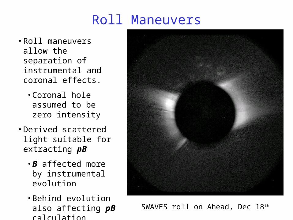
Roll Maneuvers
• Roll maneuvers allow the separation of instrumental and coronal effects.
• Coronal hole assumed to be zero intensity
• Derived scattered light suitable for extracting pB
• B affected more by instrumental evolution
• Behind evolution also affecting pB calculation
• There are several roll maneuvers now on each spacecraft.
SWAVES roll on Ahead, Dec 18th
Compression• Image compression is required to be able to bring down
data with sufficient cadence to see all CMEs.
• ICER is limited to a dynamic range of just over 13 bits.
• Dynamic range in COR1 is limited by scattered light– Top end limited by brightest part of the image, near occulter.– Bottom end limited by Poisson noise in fainter outer regions.– Resulting dynamic range is less than 13 bits for 2х2 binning for
both COR1A and COR1B
• Strategy is to select a compression mode that keeps the digital noise below the Poisson noise.– Binning to 1024х1024 first improves statistics
• Optics designed for 1024х1024 operation
– Selected ICER 05 compression mode– Space weather: 128х128 binned with ICER 11

Observing Plans• Three polarizer positions (0°, 120°, 240°) taken
in rapid sequence
• All images binned to 1024х1024 resolution
• Currently planning on IP-binning for better linearity– May need to go to CCD-binning to reduce radiation-
induced noise
• Images scaled to 13 bits and compressed with ICER 05
• Complete polarizer sequence repeated every 10 minutes– SSR2 data decreases cadence to 5 minutes for few
hours

Removing Scattered Light• Polarized brightness (pB) calculation removes much of the scattered light.
– Still some residual scattered light• Running and base difference movies also work well
– Jitter sensitivity less for B than for pB• Other strategies include:
– Removing model derived from calibration rolls• Works well for pB• Instrument evolution limits effectiveness for B
– Monthly minimum image technique• Effect of instrument evolution not yet clear
– Daily minimum image technique• Mainly effective for CMEs
• Above models are applied to each polarization component before combining into pB

Behind AheadpB
Without Background Subtraction• Most of the scattered light is removed by the pB calculation.
Behind AheadB
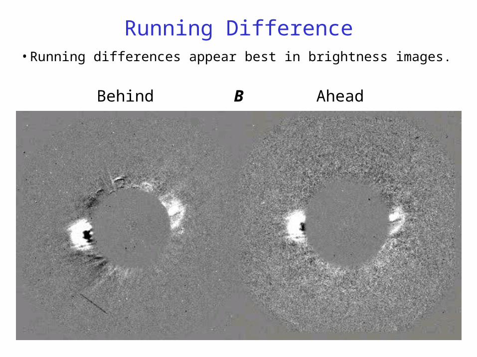
Running Difference• Running differences appear best in brightness images.

Behind AheadpB
Subtracting Rotation Model• Most representative of corona. Instrument evolution so far restricts use
to pB.
Behind AheadpB
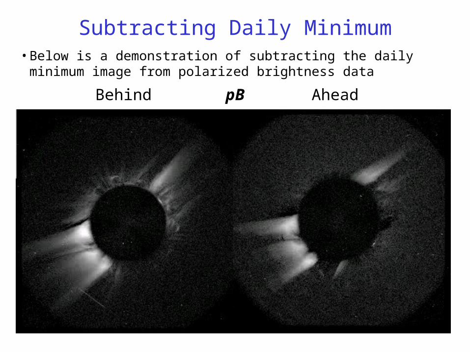
Subtracting Daily Minimum• Below is a demonstration of subtracting the daily minimum image from
polarized brightness data

Behind AheadB
Subtracting Daily Minimum• It also works for total brightness. Some evolution in background can be
seen for Ahead.

Extra Slides

Instrument Performance
•The measured straylight is lower than the model predictions.
•The K corona is fainter than the stray light, but significantly brighter than the noise floor.
•When the 3 polarization angles are combined, the pB of the K corona is recovered from the unpolarized background
•CMEs are visible from the occulter to the detector edge.
Signal to noise ratio
Relative brightness
Requirement
A
B

Resolution
Sample subfield image (COR-1A)
• Resolution tested by projecting Air Force resolution test target onto various portions of the detector.
• Measurements done in vacuum, to avoid problems with air vs. vacuum focal lengths.
• Were able to resolve with high contrast all the way down to the Nyquist frequency.

Flat Field
• The field is highly flat, with discrete areas of vignetting near the occulter and camera aperture edges.
• The flat field is monitored in flight with the diffuser window mounted in the door.
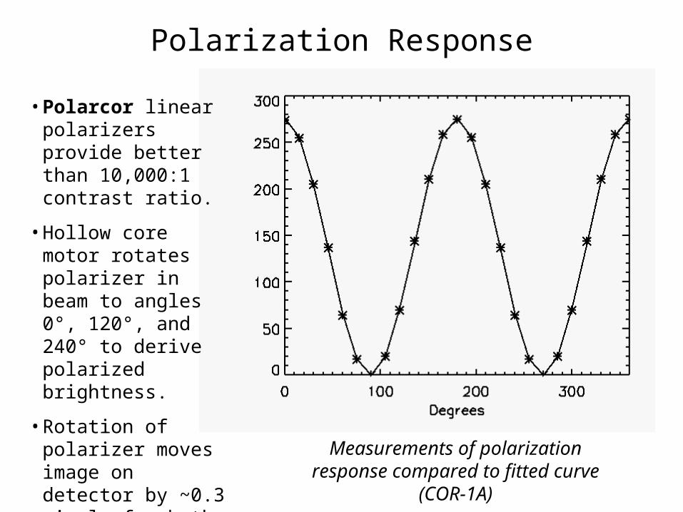
Polarization Response
• Polarcor linear polarizers provide better than 10,000:1 contrast ratio.
• Hollow core motor rotates polarizer in beam to angles 0°, 120°, and 240° to derive polarized brightness.
• Rotation of polarizer moves image on detector by ~0.3 pixels for both COR-1A & B. Minimized by putting slight tilt on polarizer. Measurements of polarization response
compared to fitted curve (COR-1A)