COPYRIGHTED MATERIALcatalogimages.wiley.com/images/db/pdf/0471268917.excerpt.pdf · Thus a material...
15
1 1 INTRODUCTION 1.1 DEFINITION The word ‘‘composite’’ means ‘‘consisting of two or more distinct parts.’’ Thus a material having two or more distinct constituent materials or phases may be considered a composite material. However, we recognize materials as composites only when the constituent phases have significantly different phys- ical properties, and thus the composite properties are noticeably different from the constituent properties. For example, common metals almost always con- tain unwanted impurities or alloying elements; plastics generally contain small quantities of fillers, lubricants, ultraviolet absorbers, and other materials for commercial reasons such as economy and ease of processing, yet these gen- erally are not classified as composites. In the case of metals, the constituent phases often have nearly identical properties (e.g., modulus of elasticity), the phases are not generally fibrous in character, and one of the phases usually is present in small-volume fractions. Thus the modulus of elasticity of a steel alloy is insensitive to the amount of the carbide present, and metallurgists generally have not considered metal alloys as composites, particularly from the point of view of analysis. Nevertheless, two-phase metal alloys are good examples of particulate composites in terms of structure. Although plastics— which are filled for cost purposes and contain small amounts of additives— are composites, they need not be considered as such if their physical prop- erties are not greatly affected by the additives. Thus classification of certain materials as composites often is based on cases where significant property changes occur as a result of the combination of constituents, and these prop- erty changes generally will be most obvious when one of the phases is in platelet or fibrous form, when the volume fraction is greater than 10%, and when the property of one constituent is much greater (5 times) than the other. COPYRIGHTED MATERIAL
Transcript of COPYRIGHTED MATERIALcatalogimages.wiley.com/images/db/pdf/0471268917.excerpt.pdf · Thus a material...
1
1
INTRODUCTION
1.1 DEFINITION
The word ‘‘composite’’ means ‘‘consisting of two or more distinct parts.’’Thus a material having two or more distinct constituent materials or phasesmay be considered a composite material. However, we recognize materials ascomposites only when the constituent phases have significantly different phys-ical properties, and thus the composite properties are noticeably different fromthe constituent properties. For example, common metals almost always con-tain unwanted impurities or alloying elements; plastics generally contain smallquantities of fillers, lubricants, ultraviolet absorbers, and other materials forcommercial reasons such as economy and ease of processing, yet these gen-erally are not classified as composites. In the case of metals, the constituentphases often have nearly identical properties (e.g., modulus of elasticity), thephases are not generally fibrous in character, and one of the phases usuallyis present in small-volume fractions. Thus the modulus of elasticity of a steelalloy is insensitive to the amount of the carbide present, and metallurgistsgenerally have not considered metal alloys as composites, particularly fromthe point of view of analysis. Nevertheless, two-phase metal alloys are goodexamples of particulate composites in terms of structure. Although plastics—which are filled for cost purposes and contain small amounts of additives—are composites, they need not be considered as such if their physical prop-erties are not greatly affected by the additives. Thus classification of certainmaterials as composites often is based on cases where significant propertychanges occur as a result of the combination of constituents, and these prop-erty changes generally will be most obvious when one of the phases is inplatelet or fibrous form, when the volume fraction is greater than 10%, andwhen the property of one constituent is much greater (�5 times) than theother.
COPYRIG
HTED M
ATERIAL
2 INTRODUCTION
Within this wide range of composite materials, a definition may be adoptedto suit one’s requirements. For the purpose of discussion in this book, com-posites can be considered to be materials consisting of two or more chemicallydistinct constituents, on a macroscale, having a distinct interface separatingthem. This definition encompasses the fiber composite materials of primaryinterest in this text. This definition also encompasses many other types ofcomposites that are not treated specifically in this book.
1.2 CHARACTERISTICS
Composites consist of one or more discontinuous phases embedded in a con-tinuous phase. The discontinuous phase is usually harder and stronger thanthe continuous phase and is called the reinforcement or reinforcing material,whereas the continuous phase is termed the matrix. The most notable excep-tion to this rule is the class of materials known as rubber-modified polymers,consisting of a rigid polymer matrix filled with rubber particles.
Properties of composites are strongly influenced by the properties of theirconstituent materials, their distribution, and the interaction among them. Thecomposite properties may be the volume-fraction sum of the properties of theconstituents, or the constituents may interact in a synergistic way so as toprovide properties in the composite that are not accounted for by a simplevolume-fraction sum of the properties of the constituents. Thus, in describinga composite material as a system, besides specifying the constituent materialsand their properties, one needs to specify the geometry of the reinforcementwith reference to the system. The geometry of the reinforcement may bedescribed by the shape, size, and size distribution. However, systems contain-ing reinforcements with identical geometry may differ from each other inmany ways; for example, the reinforcement in the systems may differ inconcentration, concentration distribution, and orientation. Therefore, all thesefactors may be important in determining the properties of the composites, butseldom are all accounted for in the development of theoretical descriptionsof composites.
The shape of the discrete units of the discontinuous phase often may beapproximated by spheres or cylinders. There are some natural materials suchas mica and the clay minerals and some man-made materials such as glassflakes that can best be described by rectangular cross-sectioned prisms orplatelets. The size and size distribution control the texture of the material.Together with volume fraction, they also determine the interfacial area, whichplays an important role in determining the extent of the interaction betweenthe reinforcement and the matrix.
Concentration is usually measured in terms of volume or weight fraction.The contribution of a single constituent to the overall properties of the com-posite is determined by this parameter. The concentration generally is re-garded as the single most important parameter influencing the compositeproperties. Also, it is an easily controllable manufacturing variable used to
1.3 CLASSIFICATION 3
alter the properties of the composite. The concentration distribution is a mea-sure of homogeneity or uniformity of the system. The homogeneity is animportant characteristic that determines the extent to which a representativevolume of material may differ in physical and mechanical properties from theaverage properties of the material. Nonuniformity of the system should beavoided because it reduces those properties that are governed by the weakestlink in the material. For example, failure in a nonuniform material will initiatein an area of lowest strength, thus adversely affecting the overall strength ofthe material.
The orientation of the reinforcement affects the isotropy of the system.When the reinforcement is in the form of particles, with all their dimensionsapproximately equal (equiaxed), the composite behaves essentially as an iso-tropic material whose properties are independent of direction. When the di-mensions of the representative reinforcement particles are unequal, thecomposite may behave as an isotropic material provided that the particles arerandomly oriented, such as in the randomly oriented short-fiber-reinforcedcomposites. In other cases the manufacturing process (e.g., molding of ashort-fiber composite) may induce orientation of the reinforcement and henceinduce some anisotropy. In continuous-fiber-reinforced composites, such asunidirectional or cross-ply composites, anisotropy may be desirable. More-over, the primary advantage of these composites is the ability to control an-isotropy by design and fabrication.
The concentration distribution of the particles refers to their spatial rela-tions to each other. Particles may by uniformly dispersed in a composite andplaced at regular spacings so that no two particles touch each other. On theother hand, it is possible to imagine a dispersion of particles so arranged thatthey form a network such that a continuous path connects all particles. Thishappens at a much lower concentration than that at which the close packingof particles becomes possible. Such network-forming dispersions may have asignificant influence on the electrical properties of the composites. An inter-esting example of this is the dispersion of carbon black in rubber. Above avolume concentration of about 10%, the electrical conductivity of the mixtureincreases markedly. This has been attributed to the network formation ofcarbon-black particles.
1.3 CLASSIFICATION
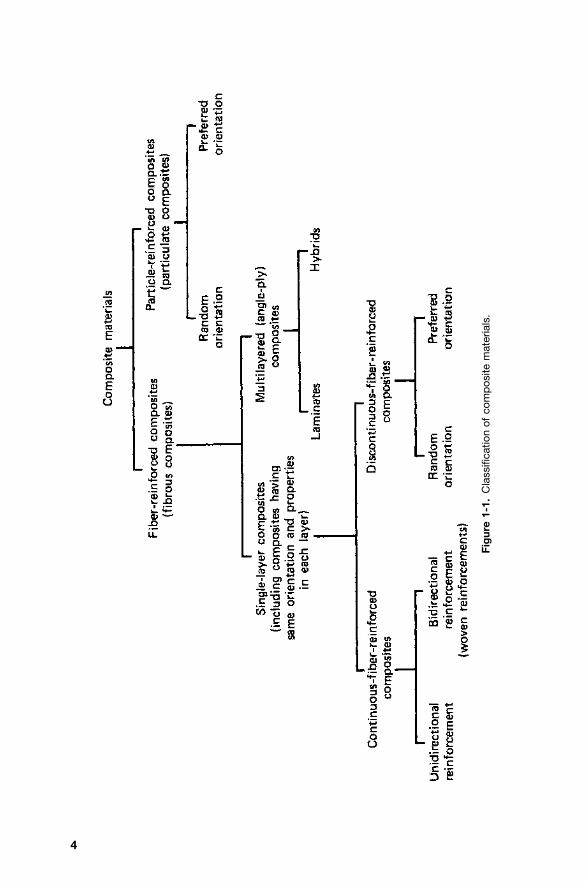
Most composite materials developed thus far have been fabricated to improvemechanical properties such as strength, stiffness, toughness, and high-temperature performance. It is natural to study together the composites thathave a common strengthening mechanism. The strengthening mechanismstrongly depends on the geometry of the reinforcement. Therefore, it is quiteconvenient to classify composite materials on the basis of the geometry of arepresentative unit of reinforcement. Figure 1-1 represents a commonly ac-cepted classification scheme for composite materials.
4
Fig
ure
1-1.
Cla
ssifi
catio
nof
com
pos
item
ater
ials
.
1.4 PARTICULATE COMPOSITES 5
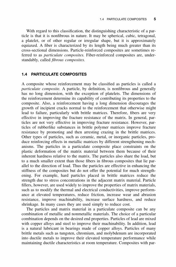
With regard to this classification, the distinguishing characteristic of a par-ticle is that it is nonfibrous in nature. It may be spherical, cubic, tetragonal,a platelet, or of other regular or irregular shape, but it is approximatelyequiaxed. A fiber is characterized by its length being much greater than itscross-sectional dimensions. Particle-reinforced composites are sometimes re-ferred to as particulate composites. Fiber-reinforced composites are, under-standably, called fibrous composites.
1.4 PARTICULATE COMPOSITES
A composite whose reinforcement may be classified as particles is called aparticulate composite. A particle, by definition, is nonfibrous and generallyhas no long dimension, with the exception of platelets. The dimensions ofthe reinforcement determine its capability of contributing its properties to thecomposite. Also, a reinforcement having a long dimension discourages thegrowth of incipient cracks normal to the reinforcement that otherwise mightlead to failure, particularly with brittle matrices. Therefore, fibers are veryeffective in improving the fracture resistance of the matrix. In general, par-ticles are not very effective in improving fracture resistance. However, par-ticles of rubberlike substances in brittle polymer matrices improve fractureresistance by promoting and then arresting crazing in the brittle matrices.Other types of particles, such as ceramic, metal, or inorganic particles, pro-duce reinforcing effects in metallic matrices by different strengthening mech-anisms. The particles in a particulate composite place constraints on theplastic deformation of the matrix material between them because of theirinherent hardness relative to the matrix. The particles also share the load, butto a much smaller extent than those fibers in fibrous composites that lie par-allel to the direction of load. Thus the particles are effective in enhancing thestiffness of the composites but do not offer the potential for much strength-ening. For example, hard particles placed in brittle matrices reduce thestrength due to stress concentrations in the adjacent matrix material. Particlefillers, however, are used widely to improve the properties of matrix materials,such as to modify the thermal and electrical conductivities, improve perform-ance at elevated temperatures, reduce friction, increase wear and abrasionresistance, improve machinability, increase surface hardness, and reduceshrinkage. In many cases they are used simply to reduce cost.
The particles and matrix material in a particulate composite can be anycombination of metallic and nonmetallic materials. The choice of a particularcombination depends on the desired end properties. Particles of lead are mixedwith copper alloys and steel to improve their machinability. In addition, leadis a natural lubricant in bearings made of copper alloys. Particles of manybrittle metals such as tungsten, chromium, and molybdenum are incorporatedinto ductile metals to improve their elevated temperature performance whilemaintaining ductile characteristics at room temperature. Composites with par-
6 INTRODUCTION
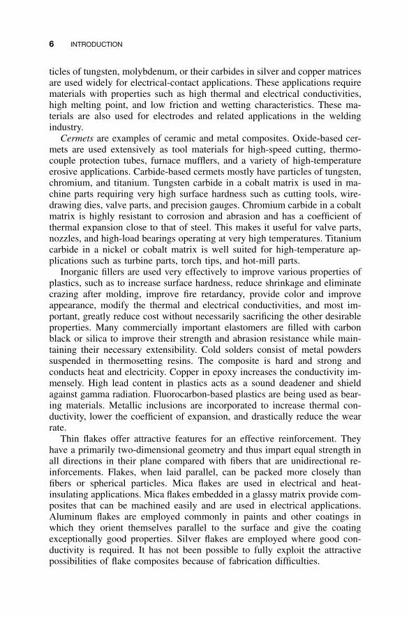
ticles of tungsten, molybdenum, or their carbides in silver and copper matricesare used widely for electrical-contact applications. These applications requirematerials with properties such as high thermal and electrical conductivities,high melting point, and low friction and wetting characteristics. These ma-terials are also used for electrodes and related applications in the weldingindustry.
Cermets are examples of ceramic and metal composites. Oxide-based cer-mets are used extensively as tool materials for high-speed cutting, thermo-couple protection tubes, furnace mufflers, and a variety of high-temperatureerosive applications. Carbide-based cermets mostly have particles of tungsten,chromium, and titanium. Tungsten carbide in a cobalt matrix is used in ma-chine parts requiring very high surface hardness such as cutting tools, wire-drawing dies, valve parts, and precision gauges. Chromium carbide in a cobaltmatrix is highly resistant to corrosion and abrasion and has a coefficient ofthermal expansion close to that of steel. This makes it useful for valve parts,nozzles, and high-load bearings operating at very high temperatures. Titaniumcarbide in a nickel or cobalt matrix is well suited for high-temperature ap-plications such as turbine parts, torch tips, and hot-mill parts.
Inorganic fillers are used very effectively to improve various properties ofplastics, such as to increase surface hardness, reduce shrinkage and eliminatecrazing after molding, improve fire retardancy, provide color and improveappearance, modify the thermal and electrical conductivities, and most im-portant, greatly reduce cost without necessarily sacrificing the other desirableproperties. Many commercially important elastomers are filled with carbonblack or silica to improve their strength and abrasion resistance while main-taining their necessary extensibility. Cold solders consist of metal powderssuspended in thermosetting resins. The composite is hard and strong andconducts heat and electricity. Copper in epoxy increases the conductivity im-mensely. High lead content in plastics acts as a sound deadener and shieldagainst gamma radiation. Fluorocarbon-based plastics are being used as bear-ing materials. Metallic inclusions are incorporated to increase thermal con-ductivity, lower the coefficient of expansion, and drastically reduce the wearrate.
Thin flakes offer attractive features for an effective reinforcement. Theyhave a primarily two-dimensional geometry and thus impart equal strength inall directions in their plane compared with fibers that are unidirectional re-inforcements. Flakes, when laid parallel, can be packed more closely thanfibers or spherical particles. Mica flakes are used in electrical and heat-insulating applications. Mica flakes embedded in a glassy matrix provide com-posites that can be machined easily and are used in electrical applications.Aluminum flakes are employed commonly in paints and other coatings inwhich they orient themselves parallel to the surface and give the coatingexceptionally good properties. Silver flakes are employed where good con-ductivity is required. It has not been possible to fully exploit the attractivepossibilities of flake composites because of fabrication difficulties.
1.5 FIBER-REINFORCED COMPOSITES 7
Nanocomposites, which are emerging new composites, are discussed inChap. 11. Clay-reinforced nanocomposites are particulate composites. Whilenanotubes are fibrous in character, their size is very small compared withconventional fibrous reinforcements. Therefore, nanotube-reinforced nano-composites also may be analyzed as particulate composites, especially sincenanotube concentration is very small.
Particulate composites are an important class of composite materials. Thediscussion in this text, however, deals primarily with fiber composites.
1.5 FIBER-REINFORCED COMPOSITES
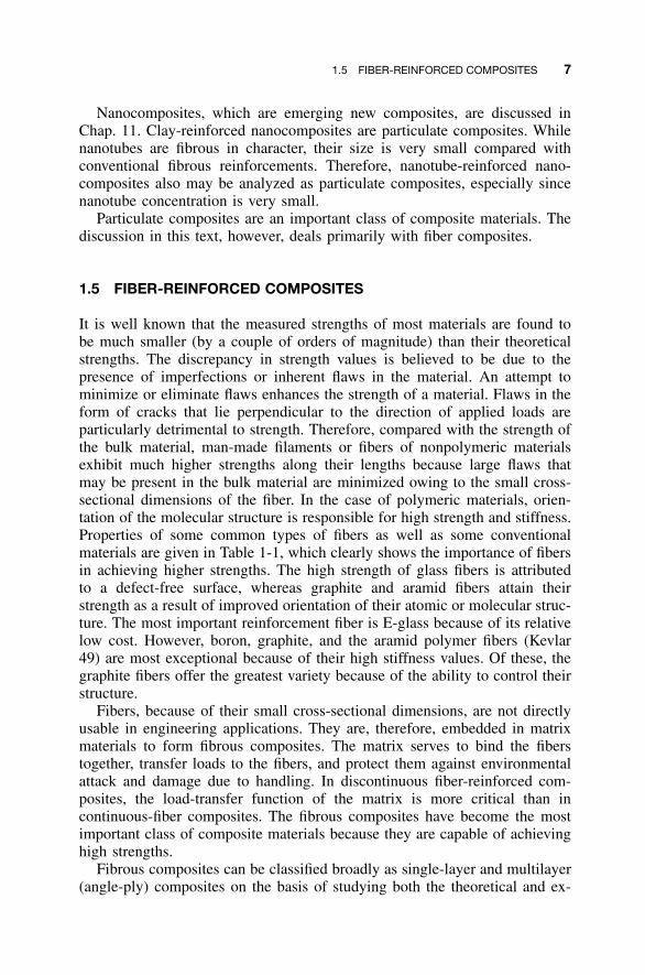
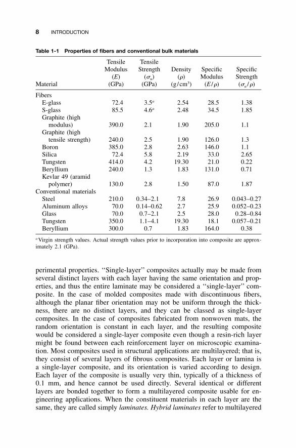
It is well known that the measured strengths of most materials are found tobe much smaller (by a couple of orders of magnitude) than their theoreticalstrengths. The discrepancy in strength values is believed to be due to thepresence of imperfections or inherent flaws in the material. An attempt tominimize or eliminate flaws enhances the strength of a material. Flaws in theform of cracks that lie perpendicular to the direction of applied loads areparticularly detrimental to strength. Therefore, compared with the strength ofthe bulk material, man-made filaments or fibers of nonpolymeric materialsexhibit much higher strengths along their lengths because large flaws thatmay be present in the bulk material are minimized owing to the small cross-sectional dimensions of the fiber. In the case of polymeric materials, orien-tation of the molecular structure is responsible for high strength and stiffness.Properties of some common types of fibers as well as some conventionalmaterials are given in Table 1-1, which clearly shows the importance of fibersin achieving higher strengths. The high strength of glass fibers is attributedto a defect-free surface, whereas graphite and aramid fibers attain theirstrength as a result of improved orientation of their atomic or molecular struc-ture. The most important reinforcement fiber is E-glass because of its relativelow cost. However, boron, graphite, and the aramid polymer fibers (Kevlar49) are most exceptional because of their high stiffness values. Of these, thegraphite fibers offer the greatest variety because of the ability to control theirstructure.
Fibers, because of their small cross-sectional dimensions, are not directlyusable in engineering applications. They are, therefore, embedded in matrixmaterials to form fibrous composites. The matrix serves to bind the fiberstogether, transfer loads to the fibers, and protect them against environmentalattack and damage due to handling. In discontinuous fiber-reinforced com-posites, the load-transfer function of the matrix is more critical than incontinuous-fiber composites. The fibrous composites have become the mostimportant class of composite materials because they are capable of achievinghigh strengths.
Fibrous composites can be classified broadly as single-layer and multilayer(angle-ply) composites on the basis of studying both the theoretical and ex-
8 INTRODUCTION
Table 1-1 Properties of fibers and conventional bulk materials
Material
TensileModulus
(E)(GPa)
TensileStrength
(�u)(GPa)
Density(�)
(g /cm3)
SpecificModulus
(E /�)
SpecificStrength(�u /�)
FibersE-glassS-glassGraphite (high
modulus)Graphite (high
tensile strength)BoronSilicaTungstenBerylliumKevlar 49 (aramid
polymer)Conventional materials
SteelAluminum alloysGlassTungstenBeryllium
72.485.5
390.0
240.0385.0
72.4414.0240.0
130.0
210.070.070.0
350.0300.0
3.5a
4.6a
2.1
2.52.85.84.21.3
2.8
0.34–2.10.14–0.62
0.7–2.11.1–4.1
0.7
2.542.48
1.90
1.902.632.19
19.301.83
1.50
7.82.72.5
19.301.83
28.534.5
205.0
126.0146.033.021.0
131.0
87.0
26.925.928.018.1
164.0
1.381.85
1.1
1.31.12.650.220.71
1.87
0.043–0.270.052–0.230.28–0.84
0.057–0.210.38
a Virgin strength values. Actual strength values prior to incorporation into composite are approx-imately 2.1 (GPa).
perimental properties. ‘‘Single-layer’’ composites actually may be made fromseveral distinct layers with each layer having the same orientation and prop-erties, and thus the entire laminate may be considered a ‘‘single-layer’’ com-posite. In the case of molded composites made with discontinuous fibers,although the planar fiber orientation may not be uniform through the thick-ness, there are no distinct layers, and they can be classed as single-layercomposites. In the case of composites fabricated from nonwoven mats, therandom orientation is constant in each layer, and the resulting compositewould be considered a single-layer composite even though a resin-rich layermight be found between each reinforcement layer on microscopic examina-tion. Most composites used in structural applications are multilayered; that is,they consist of several layers of fibrous composites. Each layer or lamina isa single-layer composite, and its orientation is varied according to design.Each layer of the composite is usually very thin, typically of a thickness of0.1 mm, and hence cannot be used directly. Several identical or differentlayers are bonded together to form a multilayered composite usable for en-gineering applications. When the constituent materials in each layer are thesame, they are called simply laminates. Hybrid laminates refer to multilayered
1.5 FIBER-REINFORCED COMPOSITES 9
composites consisting of layers made up of different constituent materials.For example, one layer of a hybrid laminate may be a glass-fiber-reinforcedepoxy, whereas another layer may be graphite-fiber-reinforced epoxy. It ispossible, but not as common, to find hybrid composites having a mixture offibers within the single layer. A single layer of a composite, therefore, rep-resents a basic building block for its structural applications.
Reinforcing fibers in a single-layer composite may be short or longcompared with its overall dimensions. Composites with long fibers arecalled continuous-fiber-reinforced composites, and those with short fibers,discontinuous-fiber-reinforced composites. A further distinction is that adiscontinuous-fiber composite can be considered to be one in which the fiberlength affects the properties of the composite. In continuous-fiber-reinforcedcomposites it may be assumed that the load is applied directly to the fibersand that the fibers in the direction of load are the principal load-carryingconstituent. The latter assumption is particularly valid when high-modulusfibers are used in large concentrations. Thus the principal purpose of a matrixis not to be a load-carrying constituent but essentially to bind the fibers to-gether and protect them. The failure mode of such composites is also gen-erally controlled by the fibers.
The continuous fibers in a ‘‘single-layer’’ composite may be all aligned inone direction to form a unidirectional composite. Such composites are fab-ricated by laying the fibers parallel and saturating them with resinous material,such as polyester or epoxy resin, that holds the fibers in position and servesas the matrix material. Such forms of preimpregnated fibers are called pre-pregs. Generally, a removable backing is also provided to prevent the layersfrom sticking together while being stored. The backing provides additionalmeans to hold the fibers in position. The unidirectional composites are verystrong in the fiber direction but generally are weak in the direction perpen-dicular to the fibers. Therefore, unidirectional prepregs are stacked togetherin various orientations to form laminates usable in engineering applications.However, unidirectionally glass-reinforced adhesive tapes are used widely forheavy-duty sealing applications, and some unidirectional composites are usedfor fishing poles and other rodlike structures.
The continuous reinforcement in a single layer also may be provided in asecond direction to achieve more balanced properties. The bidirectional re-inforcement may be provided in a single layer in mutually perpendiculardirections as in a woven fabric. The bidirectional reinforcement may be suchthat the strengths in two perpendicular directions are approximately equal. Insome applications, a minimum of reinforcement perpendicular to the primarydirection is provided only to prevent damage and fiber separation in handlingowing to the poor strength in the transverse direction. In such cases, thetransverse strength is much less than the strength in the direction of primaryreinforcement.
The orientation of short or discontinuous fibers cannot be controlled easilyin a composite material. In most cases, the fibers are assumed to be randomly
10 INTRODUCTION
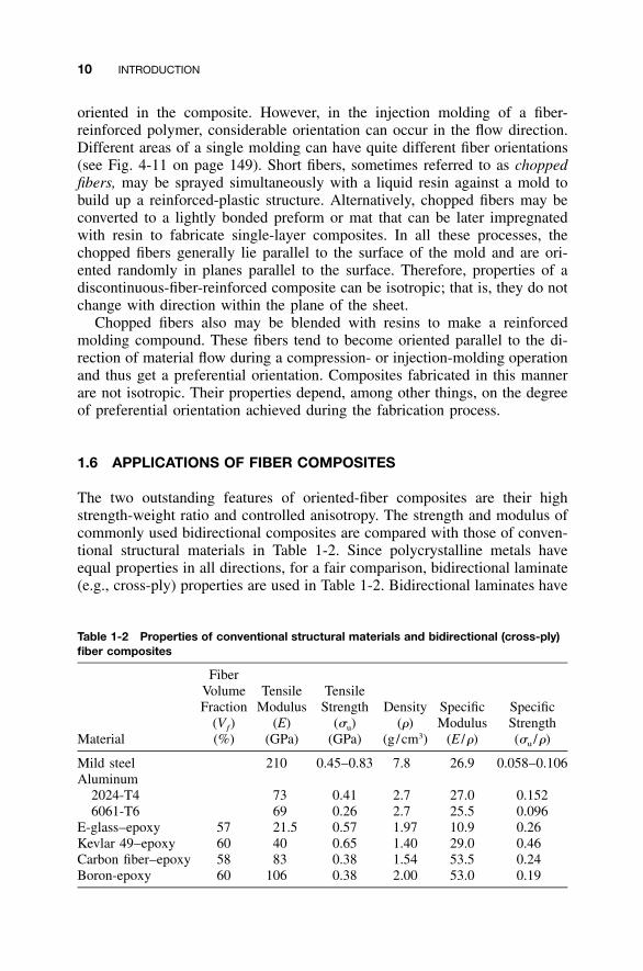
Table 1-2 Properties of conventional structural materials and bidirectional (cross-ply)fiber composites
Material
FiberVolumeFraction
(Vƒ)(%)
TensileModulus
(E)(GPa)
TensileStrength
(�u)(GPa)
Density(�)
(g /cm3)
SpecificModulus
(E /�)
SpecificStrength(�u /�)
Mild steel 210 0.45–0.83 7.8 26.9 0.058–0.106Aluminum
2024-T4 73 0.41 2.7 27.0 0.1526061-T6 69 0.26 2.7 25.5 0.096
E-glass–epoxy 57 21.5 0.57 1.97 10.9 0.26Kevlar 49–epoxy 60 40 0.65 1.40 29.0 0.46Carbon fiber–epoxy 58 83 0.38 1.54 53.5 0.24Boron-epoxy 60 106 0.38 2.00 53.0 0.19
oriented in the composite. However, in the injection molding of a fiber-reinforced polymer, considerable orientation can occur in the flow direction.Different areas of a single molding can have quite different fiber orientations(see Fig. 4-11 on page 149). Short fibers, sometimes referred to as choppedfibers, may be sprayed simultaneously with a liquid resin against a mold tobuild up a reinforced-plastic structure. Alternatively, chopped fibers may beconverted to a lightly bonded preform or mat that can be later impregnatedwith resin to fabricate single-layer composites. In all these processes, thechopped fibers generally lie parallel to the surface of the mold and are ori-ented randomly in planes parallel to the surface. Therefore, properties of adiscontinuous-fiber-reinforced composite can be isotropic; that is, they do notchange with direction within the plane of the sheet.
Chopped fibers also may be blended with resins to make a reinforcedmolding compound. These fibers tend to become oriented parallel to the di-rection of material flow during a compression- or injection-molding operationand thus get a preferential orientation. Composites fabricated in this mannerare not isotropic. Their properties depend, among other things, on the degreeof preferential orientation achieved during the fabrication process.
1.6 APPLICATIONS OF FIBER COMPOSITES
The two outstanding features of oriented-fiber composites are their highstrength-weight ratio and controlled anisotropy. The strength and modulus ofcommonly used bidirectional composites are compared with those of conven-tional structural materials in Table 1-2. Since polycrystalline metals haveequal properties in all directions, for a fair comparison, bidirectional laminate(e.g., cross-ply) properties are used in Table 1-2. Bidirectional laminates have
1.6 APPLICATIONS OF FIBER COMPOSITES 11
and GDP. Adapted from MacNeil [1]
Ind
ex 1
960
= 10
0
Year
Steel
GDP
Aluminum
Composites
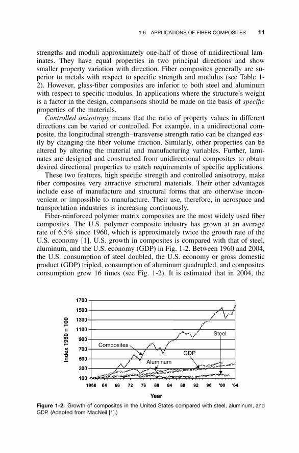
Figure 1-2. Growth of composites in the United States compared with steel, aluminum, andGDP. (Adapted from MacNeil [1].)
strengths and moduli approximately one-half of those of unidirectional lam-inates. They have equal properties in two principal directions and showsmaller property variation with direction. Fiber composites generally are su-perior to metals with respect to specific strength and modulus (see Table 1-2). However, glass-fiber composites are inferior to both steel and aluminumwith respect to specific modulus. In applications where the structure’s weightis a factor in the design, comparisons should be made on the basis of specificproperties of the materials.
Controlled anisotropy means that the ratio of property values in differentdirections can be varied or controlled. For example, in a unidirectional com-posite, the longitudinal strength–transverse strength ratio can be changed eas-ily by changing the fiber volume fraction. Similarly, other properties can bealtered by altering the material and manufacturing variables. Further, lami-nates are designed and constructed from unidirectional composites to obtaindesired directional properties to match requirements of specific applications.
These two features, high specific strength and controlled anisotropy, makefiber composites very attractive structural materials. Their other advantagesinclude ease of manufacture and structural forms that are otherwise incon-venient or impossible to manufacture. Their use, therefore, in aerospace andtransportation industries is increasing continuously.
Fiber-reinforced polymer matrix composites are the most widely used fibercomposites. The U.S. polymer composite industry has grown at an averagerate of 6.5% since 1960, which is approximately twice the growth rate of theU.S. economy [1]. U.S. growth in composites is compared with that of steel,aluminum, and the U.S. economy (GDP) in Fig. 1-2. Between 1960 and 2004,the U.S. consumption of steel doubled, the U.S. economy or gross domesticproduct (GDP) tripled, consumption of aluminum quadrupled, and compositesconsumption grew 16 times (see Fig. 1-2). It is estimated that in 2004, the
12 INTRODUCTION
Transport32%
Marine10%
Electrical10%
Corrosion12%
Consumer7%
Construction20%
Appliance5%
Aircraft1%
Other3%
Estimated 2004 composites consumption: 1.8 � 109 kg (4.0 billion lb)
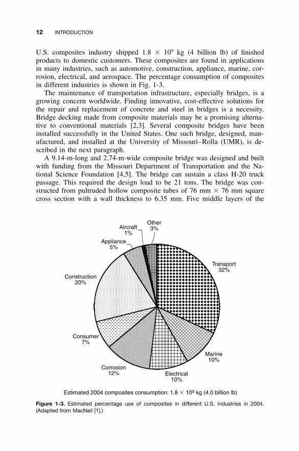
Figure 1-3. Estimated percentage use of composites in different U.S. industries in 2004.(Adapted from MacNeil [1].)
U.S. composites industry shipped 1.8 � 109 kg (4 billion lb) of finishedproducts to domestic customers. These composites are found in applicationsin many industries, such as automotive, construction, appliance, marine, cor-rosion, electrical, and aerospace. The percentage consumption of compositesin different industries is shown in Fig. 1-3.
The maintenance of transportation infrastructure, especially bridges, is agrowing concern worldwide. Finding innovative, cost-effective solutions forthe repair and replacement of concrete and steel in bridges is a necessity.Bridge decking made from composite materials may be a promising alterna-tive to conventional materials [2,3]. Several composite bridges have beeninstalled successfully in the United States. One such bridge, designed, man-ufactured, and installed at the University of Missouri–Rolla (UMR), is de-scribed in the next paragraph.
A 9.14-m-long and 2.74-m-wide composite bridge was designed and builtwith funding from the Missouri Department of Transportation and the Na-tional Science Foundation [4,5]. The bridge can sustain a class H-20 truckpassage. This required the design load to be 21 tons. The bridge was con-structed from pultruded hollow composite tubes of 76 mm � 76 mm squarecross section with a wall thickness to 6.35 mm. Five middle layers of the
1.6 APPLICATIONS OF FIBER COMPOSITES 13
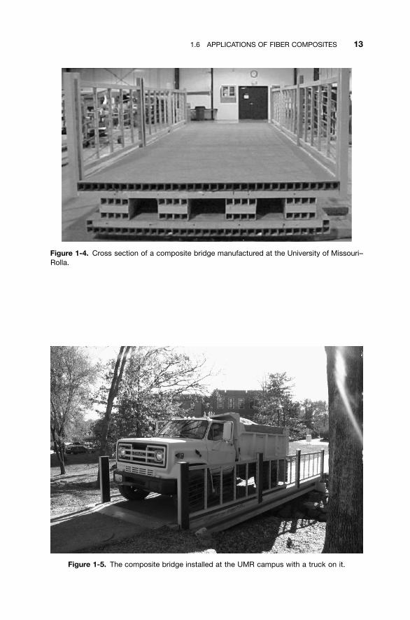
Figure 1-4. Cross section of a composite bridge manufactured at the University of Missouri–Rolla.
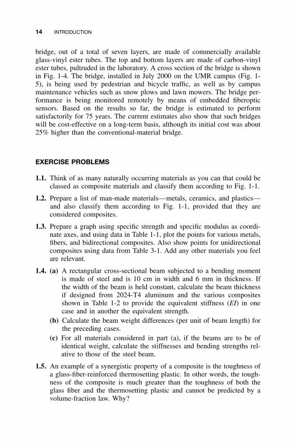
Figure 1-5. The composite bridge installed at the UMR campus with a truck on it.
14 INTRODUCTION
bridge, out of a total of seven layers, are made of commercially availableglass-vinyl ester tubes. The top and bottom layers are made of carbon-vinylester tubes, pultruded in the laboratory. A cross section of the bridge is shownin Fig. 1-4. The bridge, installed in July 2000 on the UMR campus (Fig. 1-5), is being used by pedestrian and bicycle traffic, as well as by campusmaintenance vehicles such as snow plows and lawn mowers. The bridge per-formance is being monitored remotely by means of embedded fiberopticsensors. Based on the results so far, the bridge is estimated to performsatisfactorily for 75 years. The current estimates also show that such bridgeswill be cost-effective on a long-term basis, although its initial cost was about25% higher than the conventional-material bridge.
EXERCISE PROBLEMS
1.1. Think of as many naturally occurring materials as you can that could beclassed as composite materials and classify them according to Fig. 1-1.
1.2. Prepare a list of man-made materials—metals, ceramics, and plastics—and also classify them according to Fig. 1-1, provided that they areconsidered composites.
1.3. Prepare a graph using specific strength and specific modulus as coordi-nate axes, and using data in Table 1-1, plot the points for various metals,fibers, and bidirectional composites. Also show points for unidirectionalcomposites using data from Table 3-1. Add any other materials you feelare relevant.
1.4. (a) A rectangular cross-sectional beam subjected to a bending momentis made of steel and is 10 cm in width and 6 mm in thickness. Ifthe width of the beam is held constant, calculate the beam thicknessif designed from 2024-T4 aluminum and the various compositesshown in Table 1-2 to provide the equivalent stiffness (EI) in onecase and in another the equivalent strength.
(b) Calculate the beam weight differences (per unit of beam length) forthe preceding cases.
(c) For all materials considered in part (a), if the beams are to be ofidentical weight, calculate the stiffnesses and bending strengths rel-ative to those of the steel beam.
1.5. An example of a synergistic property of a composite is the toughness ofa glass-fiber-reinforced thermosetting plastic. In other words, the tough-ness of the composite is much greater than the toughness of both theglass fiber and the thermosetting plastic and cannot be predicted by avolume-fraction law. Why?
REFERENCES 15
REFERENCES
1. R. MacNeil, ‘‘U.S. Composites Market Outlook for 2005 and Beyond,’’ CompositesManufacturing, January, 16–29 (2005).
2. A. H. Zureick, B. Shih, and E. Munley, ‘‘Fiber-Reinforced Polymeric BridgeDecks,’’ Structural Engineering Review, 7, 257–266 (1995).
3. M. Chajes, J. Gillespie, D. Mertz, and H. Shenton, ‘‘Advanced Composite Bridgesin Delaware,’’ Proceedings of the Second International Conference on Compositesin Infrastructure, Tuscon, AZ, Vol. 1, 1998, pp. 645–650.
4. P. Kumar, K. Chandrashekhara, and A. Nanni, ‘‘Testing and Evaluation of Com-ponents for a Composite Bridge Deck,’’ Journal of Reinforced Composites andPlastics, 22, 441–461 (2003).
5. P. Kumar, K. Chandrashekhara, and A. Nanni, ‘‘Structural Performance of a FRPBridge Deck,’’ Construction and Building Materials, 8, 35–47 (2004).