COPYRIGHT NOTICE · ii tritoN CoNNeCt user MaNuaL Information in this document is subject to change...
257
CORPORATE HEADQUARTERS: 21405 Avenue “B” Long Beach, MS 39560 Phone: (800) 259-6672 Fax: (228) 868-9445 COPYRIGHT NOTICE © 2015 Triton. All Rights Reserved. TRITON logo is a registered trademark of Triton Systems of Delaware, LLC. TRITON CONNECT TM 6.0 USER MANUAL TDN 07103-00202-08 September 8, 2015
Transcript of COPYRIGHT NOTICE · ii tritoN CoNNeCt user MaNuaL Information in this document is subject to change...

Corporate Headquarters:
21405 Avenue “B” Long Beach, MS 39560 Phone: (800) 259-6672 Fax: (228) 868-9445
COPYRIGHT NOTICE
© 2015 Triton. All Rights Reserved. TRITON logo is a registered trademark of Triton Systems of Delaware, LLC.
TRITON CONNECTTM
6.0user MaNuaL
TDN 07103-00202-08 September 8, 2015

ii
tritoN CoNNeCt user MaNuaL
Information in this document is subject to change without notice. Companies, names and other data used in examples are fictitious unless stated otherwise.
aLL rigHts reserved
This publication is protected by copyright and all rights are reserved. No part of it may be reproduced or transmitted by any means or in any form, without prior consent in writing from Triton Systems of Delaware, LLC.
The information in this publication has been carefully checked and is believed to be accurate. However, Triton Systems of Delaware, LLC. assumes no responsibility for any inaccuracies, errors, or omissions that may be contained in this document. In no event will Triton Systems of Delaware, LLC. be liable for direct, indirect, special, incidental, or consequential damages resulting from any defect or omission in this manual, even if advised of the possibility of such damages.
In the interest of continued product development, Triton Systems of Delaware, LLC. reserves the right to make improvements in its documentation and the products it describes at any time, without notice or obligation.
tradeMark aCkNowLedgeMeNts
Microsoft Windows is a registered trademark of Microsoft Corporation in the United States and/or other countries. Triton Connect is a trademark of Triton Systems of Delaware, LLC. Intel is a registered trademark of Intel Corporation.
Triton’s Technical Services DepartmentThe primary purpose of the technical services department is to provide assistance to customers in the operation, troubleshooting, and repair of equipment manufactured by Triton. A toll-free phone number (1-800-259-6672) is provided for convenience. The technical services department operates to serve our customers. The staff is trained to follow our policies and procedures to ensure fair and uniform treatment of all our customers.
warraNty stateMeNt
Manufacturer warrants that the product delivered to a distributor will perform in accordance with the Manufacturer’s published specifications for 12 months from date of shipment in Long Beach, MS.Manufacturer’s warranty shall not apply to any damages resulting from abuse, negligence, accident, or any loss or damage to the product while in transit.Written notice and explanation of circumstances surrounding any claims that the goods have proved defective in material or workmanship shall be given promptly from the distributor to the manufacturer. No claim will be made, or action brought, by or through a distributor after the expiration of 14 months following any alleged breach of warranty.

iii
tritoN CoNNeCt user MaNuaL
autoMated teLLer MaCHiNe (“atM”) software eNd-user agreeMeNt
iMportaNt: pLease read CarefuLLy:
By INSTALLINg or oTHerWISe USINg THe ATM, yoU (AS THe oWNer or LeSSee oF THe ATM). Agree To Be BoUND By THe FoLLoWINg TerMS AND CoNDITIoNS, INCLUDINg, WITHoUT LIMITATIoN, THe WArrANTy DISCLAIMerS, LIMITATIoNS oF LIABILITy AND TerMINATIoN ProvISIoN WHICH APPLy To yoUr USe oF THe ATM SoFTWAre CoNTAINeD IN THIS ATM AND IS HereBy LICeNSeD By TrIToN SySTeMS oF DeLAWAre, LLC. (“Triton”) To yoU PUrSUANT To THIS AgreeMeNT.
IF yoU Do NoT Agree To or Are NoT WILLINg To Be BoUND By THe TerMS AND CoNDITIoNS oF THIS AgreeMeNT, Do NoT INSTALL or oTHerWISe USe THIS ATM AND ProMPTLy CoNTACT yoUr veNDor. INSTALLINg or oTHerWISe USINg THe ATM INDICATeS THAT yoU ACCePT THeSe TerMS.
This ATM is manufactured by, and utilizes proprietary software owned by Triton Systems of Delaware, LLC. and/or its suppliers. All right, title and interest in and to all component software installed or embedded in the ATM (“ATM Software”) including all associated intellectual property rights, are and will remain the property of Triton and/or its suppliers.
LICENSE: Triton grants you a limited, nonexclusive license to use the ATM Software but only in connection with the operation of this ATM subject to the terms and restrictions set forth in this License Agreement. you are not permitted to use the ATM Software in any manner not expressly authorized by this License. you acknowledge and agree that ownership of the ATM Software and all subsequent copies thereof regardless of the form or media are held by Triton or its suppliers.
The software is licensed for use on this specific Triton ATM product and may not be used on any other product. Otherwise, the supporting documentation, if any, may be copied only as essential for backup or archive purposes in support of your use of the ATM. you must reproduce and include all copyright notices and any other proprietary rights notices appearing on any copies that you make.
ASSIGNMENT: NO REVERSE ENGINEERING: you may transfer the ATM Software to another party but only in connection with a transfer of all your right, title and interest in and to this ATM and if such party accepts the terms and conditions of this License Agreement. If you transfer the ATM, you must at the same time transfer the supporting docu-mentation, if any, to the same party or destroy any such materials not transferred. Modification, reverse engineering, reverse compiling, or disassembly of the ATM and/or the ATM Software is expressly prohibited.
DISCLAIMer oF WArrANTIeS AND LIMITATIoN oF DAMAgeS
To THe eXTeNT PerMITTeD By LAW, THIS ATM SoFTWAre, INCLUDINg ALL INCorPorATeD THIrD PArTy SoFTWAre, AND DerIvATIveS IS ProvIDeD, “AS IS”. TrIToN MAKeS No rePreSeNTATIoNS WITH re-SPeCT To, AND DoeS NoT WArrANT THe PerForMANCe or reSULTS yoU or yoUr CUSToMerS MAy oBTAIN By USINg THe ATM. TrIToN SPeCIFICALLy DISCLAIMS ANy AND ALL WArrANTIeS, eXPreSS, IMPLIeD or STATUTory, INCLUDINg WITHoUT LIMITATIoN, WArrANTIeS oF QUALITy, PerForMANCe, NoNINFrINgeMeNT, AND MerCHANTABILITy or FITNeSS For ANy PArTICULAr PUrPoSe.
TrIToN MAKeS No rePreSeNTATIoNS or WArrANTIeS AND ASSUMeS No oBLIgATIoNS To yoU or yoUr CUSToMerS WITH reSPeCT To ANy TrANSACTIoN or ServICeS ACCeSSeD AND/or UTILIZeD IN CoNSUMer-INITIATeD TrANSACTIoNS MADe FroM THIS ATM. IN No eveNT WILL TrIToN, ITS AF-FILIATeS, DIreCTorS, oFFICerS, eMPLoyeeS, AgeNTS or SUPPLIerS Be LIABLe To yoU UNDer ANy THeory oF TorT, CoNTrACT, STrICT LIABILITy or oTHer LegAL or eQUITABLe THeory For ANy PUNITIve, CoNSeQUeNTIAL, INCIDeNTAL, SPeCIAL or SIMILAr DAMAgeS, INCLUDINg ANy LoSS ProFITS or LoST SAvINgS, eveN IF A TrIToN AgeNT or rePreSeNTATIve HAS BeeN ADvISeD oF THe PoSSIBILITy oF SUCH DAMAgeS, or For ANy CLAIM By ANy THIrD PArTy.

iv
tritoN CoNNeCt user MaNuaL
yoUr SoLe reMeDy AgAINST TrIToN For DeFeCTIve PerForMANCe oF THe ATM SoFTWAre WILL Be LIMITeD eXCLUSIveLy To rePAIr or rePLACeMeNT oF THe ATM AND/or THe ATM SoFTWAre, AT TrIToN’S SoLe DISCreTIoN.
Any warranty pertaining to the ATM, its mechanical components exclusive of the ATM software, shall be governed and controlled by any warranty given to you by Triton in a separate document accompanying this ATM.
The foregoing limitation of liability and exclusion of certain damages will apply regardless of the success or effectiveness of other remedies.
GOVERNING LAW: This License Agreement shall be governed by the laws of the State of Mississippi and by the laws of the United States, excluding their conflicts of laws principles.
SEVERABILITY: In the event any provision of this License Agreement is found to be invalid, illegal or unenforceable, the validity, legality and enforceability of any of the remaining provisions shall not in any way be affected or impaired.
ENTIRE AGREEMENT: This License Agreement and the accompanying Limited Warranty set forth the entire agreement between you and Triton, supersedes all prior agreements, whether written or oral, with respect to the ATM Software, and may be amended only in writing signed by both parties.
v
tritoN CoNNeCt user MaNuaL
CONTENTSRefer to the Triton web site for the latest Technical Bulletins updating this product. Release notes added to the
end of this document.
CHapter 1 - iNtroduCtioN ............................................................................................1-1What is triton ConneCt? .................................................................................................................. 1-2advantages ........................................................................................................................................... 1-2Features ................................................................................................................................................ 1-2What’s neW in triton ConneCt 5.1,5.3, 5.4, 5.5, 5.6, 5.8, 5.0, 6.0, & 6.0 sP2 ................................... 1-5Features introduCed in triton ConneCt 4.4 ........................................................................................1-9Features introduCed in triton ConneCt 4.3 ...................................................................................... 1-10
CHapter 2 - iNstaLLatoN ..............................................................................................2-1triton ConneCt system ConFigurations .............................................................................................. 2-2reCommended system ConFigurations ................................................................................................. 2-4installing tCP/iP ................................................................................................................................. 2-5installation stePs - general ............................................................................................................... 2-7seCurity...............................................................................................................................................2-10ComloCK exPiration.......................................................................................................................2-13sP1, sP2 & sP3 uPgrade From triton ConneCt ...............................................................................2-14sP1, sP2 & sP3 uPgrade From triton ConneCt 6.0 ........................................................................2-16sP1, sP2 & sP3uPgrade From triton ConneCt 5.x or 4.4..............................................................2-18sP1, sP2 & sP3 server installation.................................................................................................2-21sP1, sP2 & sP3 Client installation.................................................................................................2-23migrate Journal arChives to sQl....................................................................................................2-26imPort atm PassWords From File......................................................................................................2-26Combine triton ConneCt databases...................................................................................................2-27
CHapter 3 - CaLL MoNitor ..........................................................................................3-1introduCtion ......................................................................................................................................... 3-2overvieW oF Call monitor FunCtions ................................................................................................. 3-2starting the Call monitor .................................................................................................................. 3-4shutting doWn the Call monitor ....................................................................................................... 3-4enabling/disabling the Call vieWer .................................................................................................. 3-5ConFiguring database settings ........................................................................................................... 3-5data manager oPerations ................................................................................................................... 3-6ConFiguring Call monitor tCP/iP settings ....................................................................................... 3-7First Journal timeout .......................................................................................................................... 3-8ConFiguring terminal originated Call exPiration time .................................................................... 3-8adding and removing a Call ProCessor ............................................................................................. 3-9enabling/disabling extended status text uPdating ......................................................................... 3-9vieWing Call ProCessor aCtivity in a seParate WindoW ................................................................... 3-9vieWing Call ProCessor aCtivity in a single Frame ........................................................................ 3-10disPlaying hex data on sCreen ........................................................................................................ 3-10CaPturing Call ProCessor data to a File......................................................................................... 3-10
vi
tritoN CoNNeCt user MaNuaL
redireCting the Call ProCessor data loCation ............................................................................... 3-10reserving a Call ProCessor For inComing Calls .............................................................................. 3-11ConFiguring the CommuniCations timeout duration ........................................................................ 3-11saving Flat Files ................................................................................................................................ 3-11logging data manager aCtivity to a File ........................................................................................ 3-11outPut to Csv Files .......................................................................................................................... 3-12outPut to taPe Format Files ............................................................................................................. 3-12exPort Journals ................................................................................................................................. 3-12seleCting a Call ProCessor settings dialog ................................................................................... 3-12starting a Call ProCessor ................................................................................................................. 3-13vieWing Call ProCessor aCtivity ...................................................................................................... 3-13ConFiguring Call ProCessor settings ............................................................................................... 3-13rsP - remote status Feed .................................................................................................................. 3-19
CHapter 4 - terMiNaL setup ........................................................................................4-1introduCtion ......................................................................................................................................... 4-2adding a neW terminal ...................................................................................................................... 4-2deleting a terminal ............................................................................................................................. 4-5modiFying a terminal reCord ............................................................................................................. 4-6vieWing terminal setuP ....................................................................................................................... 4-7setting the PC time Zone .................................................................................................................... 4-7ConFiguring user Fields ...................................................................................................................... 4-8sort terminals by................................................................................................................................ 4-9user Permissions ................................................................................................................................. 4-10modiFy status message settings ....................................................................................................... 4-11sChedule database baCKuP ................................................................................................................ 4-13rePair/ComPaCt/rePlaCe database .................................................................................................... 4-14serial File transFer over tCP/iP......................................................................................................4-17
CHapter 5 - gettiNg terMiNaL data ..........................................................................5-1introduCtion ......................................................................................................................................... 5-2get terminal data FunCtion ............................................................................................................... 5-2seleCting a terminal ........................................................................................................................... 5-2seleCting a data oPtion ...................................................................................................................... 5-4
CHapter 6 - status MoNitoriNg ..................................................................................6-1introduCtion ......................................................................................................................................... 6-2vieWing terminal status ...................................................................................................................... 6-2vieWing the Call list .......................................................................................................................... 6-3vieWing the Call error list ............................................................................................................... 6-5resCheduling Calls .............................................................................................................................. 6-6using the Call vieWer ......................................................................................................................... 6-7alarm monitor .................................................................................................................................... 6-9
CONTENTS

vii
tritoN CoNNeCt user MaNuaL
vieWing the status message log ....................................................................................................... 6-10
CHapter 7 - usiNg fiLters ...........................................................................................7-1introduCtion ......................................................................................................................................... 7-2the Filters menu .................................................................................................................................. 7-2Filter Creation and management ........................................................................................................ 7-3Creating a Filter .................................................................................................................................. 7-3vieWing a Filter .................................................................................................................................. 7-4saving a Filter ..................................................................................................................................... 7-4modiFying a Filter ............................................................................................................................... 7-4deleting a Filter .................................................................................................................................. 7-5Filter by Parameters............................................................................................................................7-5
CHapter 8 - terMiNaL paraMeters .............................................................................8-1introduCtion ......................................................................................................................................... 8-2aCCessing terminal Parameters .......................................................................................................... 8-2setting terminal Parameters .............................................................................................................. 8-5messages/CouPons ................................................................................................................................ 8-6status .................................................................................................................................................... 8-8iso no./oWner inFo ........................................................................................................................... 8-10emv settings ..................................................................................................................................... 8-14Comm ................................................................................................................................................... 8-15terminal totals ................................................................................................................................. 8-18text ad sCreens ................................................................................................................................ 8-19amounts .............................................................................................................................................. 8-20Cassette stat ...................................................................................................................................... 8-21version numbers ................................................................................................................................ 8-22ad graPhiCs/File manager ............................................................................................................... 8-23reCeiPt graPhiCs ................................................................................................................................. 8-27advanCed settings ............................................................................................................................. 8-29PassWords ........................................................................................................................................... 8-32surCharge ........................................................................................................................................... 8-33triton ConneCt settings .................................................................................................................... 8-37Control............................................................................................................................................... 8-39Format................................................................................................................................................. 8-42extended Parameters ......................................................................................................................... 8-43extended Parameters - ad data ........................................................................................................ 8-44extended Parameters - CouPoning .................................................................................................... 8-49extended Parameters - misC ............................................................................................................. 8-52extended Parameters - oPtional sCreens......................................................................................... 8-56extended Parameters--ProPane PumP Payment module (PPPm)......................................................8-57
CONTENTS

viii
tritoN CoNNeCt user MaNuaL
additional deviCe inFormation..........................................................................................................8-59broadCast store message..................................................................................................................8-61vieW and Change bill mix method...................................................................................................8-69
CHapter 9 - JourNaL data ...........................................................................................9-1introduCtion ......................................................................................................................................... 9-2aCCessing the Journal data FunCtion................................................................................................. 9-2vieWing Journal data .......................................................................................................................... 9-2navigation ............................................................................................................................................. 9-2Printing Journal data ......................................................................................................................... 9-3transaCtion resPonse Codes ............................................................................................................... 9-5arChiving Journal data ....................................................................................................................... 9-5vieWing arChived Journal data .......................................................................................................... 9-6masK Journal data (Pan data) .......................................................................................................... 9-7
CHapter 10 - Led sigN Messages.............................................................................10-1introduCtion ....................................................................................................................................... 10-2aCCessing the led sign messages FunCtion .................................................................................... 10-2overvieW oF the led sign messages FunCtion ................................................................................ 10-2Creating a message ............................................................................................................................ 10-4saving a message ............................................................................................................................... 10-7oPening a message ............................................................................................................................. 10-8modiFying a message ......................................................................................................................... 10-8sending a message ............................................................................................................................. 10-9revieWing messages ......................................................................................................................... 10-10
CHapter 11 - reports MaNager ................................................................................11-1introduCtion ....................................................................................................................................... 11-2aCCessing the rePorts manager........................................................................................................ 11-2vieWing rePorts ................................................................................................................................. 11-2Changing rePort Criteria .................................................................................................................. 11-2rePort vieWer .................................................................................................................................... 11-4Call Failures rePort ......................................................................................................................... 11-5Call list rePort ................................................................................................................................ 11-5Cassette Close rePort ....................................................................................................................... 11-6Cassette status rePort ...................................................................................................................... 11-7CheCK digits ....................................................................................................................................... 11-8CheCK digits triPle des ................................................................................................................... 11-8CouPon rePort .................................................................................................................................... 11-9day Close rePort ............................................................................................................................. 11-10denied transaCtions rePort ............................................................................................................ 11-11iso numbers rePort ........................................................................................................................ 11-11Journal data rePort ........................................................................................................................ 11-12
CONTENTS

ix
tritoN CoNNeCt user MaNuaL
CHapter 14 - CoupoN utiLity ....................................................................................14-1introduCtion ....................................................................................................................................... 14-2aCCessing the CouPon utility ........................................................................................................... 14-2CouPon image CharaCteristiCs .......................................................................................................... 14-2CouPon utility Features .................................................................................................................... 14-3Creating a triton ConneCt CouPon File ........................................................................................... 14-4
CHapter 15 - seCure soCket Layer (ssL) support........................................................................ 15-1
appeNdix a - terMiNaL paraMeters .................................................................................................. a-1
reLease Notes: refer to tHe tritoN web site for tHe Latest teCHNiCaL buLLetiNs updatiNg tHis produCt. reLease Notes are added to tHe eNd of tHis seCtioN.
CONTENTS
CHapter 13 - ad desigNer .........................................................................................13-1introduCtion ....................................................................................................................................... 13-2ad sCreen CharaCteristiCs ................................................................................................................ 13-2aCCessing the ad designer ................................................................................................................ 13-3ad designer Features ........................................................................................................................ 13-3Creating an ad sCreen ....................................................................................................................... 13-4
CHapter 12 - software dowNLoad ...........................................................................12-1introduCtion ....................................................................................................................................... 12-2aCCessing the soFtWare doWnload FunCtion ................................................................................... 12-2doWnloading soFtWare ...................................................................................................................... 12-2doWnload oPtions ............................................................................................................................. 12-2
Journals not doWnloaded .............................................................................................................. 11-13sCheduled Close rePort .................................................................................................................. 11-14most Common status messages rePort .......................................................................................... 11-14terminal ConFiguration rePort ...................................................................................................... 11-15terminal doWn time rePort ............................................................................................................ 11-15terminal status rePort ................................................................................................................... 11-16terminal status messages rePort ................................................................................................... 11-16terminal totals rePort ................................................................................................................... 11-17version numbers rePort .................................................................................................................. 11-17

x
tritoN CoNNeCt user MaNuaL
doCuMeNt updates
seP 18 2009 original 5.0
seP 25 2009 edits
aPr 15 2010 edits to add 5.1
mar 18,2011 edits to add 5.3
may 6, 2011 edits to add 5.4
aug 26, 2011 edits to add 5.5
may 7, 2012 edits to add 5.6
June 22, 2012 edits to add 5.6 sP1
doCuMeNt updates
Jan 29, 2013 edits to add 5.8
mar 14, 2013 edits to add 5.8 sP1
mar 30, 2015 edits to add 6.0
seP 8, 2015 edits to add 6.0 sP1,sP2 & sP3

Chapter 1 - INtrODUCtION

Chapter 1 - INtrODUCtION
1-2
What is Triton Connect?
Triton Connect is a PC (Personal Computer) basedsoftware that enables you to remotely manage one or moreTriton Systems ATMs.
Triton Connect is a proven ATM monitoring solution,which is currently being used to manage literally thousandsof Triton Systems ATMs throughout the United States andabroad.
Advantages
Triton Connect significantly increases your efficiency andreduces the costs associated with managing your ATMs.Some of the more significant advantages include:
Flexibility
Depending upon your needs, the software can be configuredto operate on either a single PC (standalone configuration),providing a single point for administration of yourterminal(s), or on multiple PCs (network configuration),allowing the distribution of terminal management tasksamong multiple personnel (an advantage in large volumeenvironments).
Convenience
The software enables you to perform a wide range ofmonitoring and control functions from the convenience ofa central location. In many cases, the need to travel to theterminal location to perform configuration or data retrievalfunctions can be eliminated, along with the associatedpersonal and travel costs.
Triton Connect can access your terminals via PSTN (PublicSwitched Telephone Network) or wherever standard (voice-grade analog) dial-up telephone service is available. Forapplications that require additional flexibility, Triton Connectoffers support for wireless, VSAT (satellite), and TCP/IP(Eithernet) communications.
Security
Multiple levels of passwork protection prevent the useof Triton Connect by unauthorized individuals. Sensitiveterminal functions receive additional protection.
FeaturesTriton Connect offers a wealth of features, all of which aredesigned to maximize the value of your investment in TritonSystems ATM products. These features can be grouped withinthe following program areas, which are really the softwareapplications that make up Triton Connect: • Terminal Manager
• Data Manager
• Call Monitor
• Call Viewer
• Alarm Monitor
Standalone PC Networked PCs
Triton Connect can run on standalone or networked PCs. Multiple terminals can be remotely controlled and monitored.

trItON CONNeCt User MaNUal
1-3
What is Triton Connect™?Triton Connect is a PC (Personal Computer) basedsoftware that enables you to remotely manage one or moreTriton Systems ATMs.Triton Connect is a proven ATM monitoring solution,which is currently being used to manage literally thousandsof Triton Systems ATMs throughout the United States andabroad.
AdvantagesTriton Connect significantly increases your efficiency andreduces the costs associated with managing your ATMs.Some of the more significant advantages include:
FlexibilityDepending upon your needs, the software can be configuredto operate on either a single PC (standalone configuration),providing a single point for administration of yourterminal(s), or on multiple PCs (network configuration),allowing the distribution of terminal management tasksamong multiple personnel (an advantage in large volumeenvironments).
ConvenienceThe software enables you to perform a wide range ofmonitoring and control functions from the convenience ofa central location. In many cases, the need to travel to theterminal location to perform configuration or data retrievalfunctions can be eliminated, along with the associatedpersonel and travel costs.
Terminal Manager Examples of the types of status information available are: • Terminal Error conditions.
• Cassette Status (cash loaded, remaining, etc.)
• Status of Last Dispense operation.
Data ManagerThe Data Manager application is designed to manage manyof the data-processing functions previously handled by theCall Monitor and Call Processors, significantly improvingthe speed and functionality of those applications.
Call MonitorThe Call Monitor gives Triton Connect the ability to makecalls to terminals (call-out operations) and receive calls fromterminals (call-in operations), using a combination dial-up,TCP/IP, wireless, or VSAT connections.The Call Monitor exercises overall control of all call activityby assigning each communications line to an application calleda Call Processor. Each Call Processor will monitor and controlthe calling activity of its associated line. The Call Processorwill make calls to terminals, automatically answer calls thatcome in from terminals, provide indications of the activitytaking place during a call, and terminate the connection atthe conclusion of a call.The Call Monitor gives even a standalone PC the ability tohandle a high volume of call activity.

Chapter 1 - INtrODUCtION
1-4
Call Viewer
The Call Viewer enables you to view the activity of allactive Call Processors from a licensed workstation onyour network. A Call Processor is a software componentthat acts as an interface medium between the Call Monitorapplication and the communications hardware (modems,telephone lines, etc.).
Triton Connect PC
Alarm Monitor
The Alarm Monitor checks incoming calls for alarmconditions that may be reported by terminals, and providesvisual indications of such conditions. A report of the alarmconditions is maintained by the Terminal Manager and maybe printed out if desired.
Triton Terminals
Dial-up, TCP/IP, Wireless, and VSAT are some of the ways Triton Connect can communicate with your terminals.

trItON CONNeCt User MaNUal
1-5
What’s New in Triton Connect 6.0 SP2
The latest release of Triton Connect has a number of new and modified features.The following is a list of features that are either new or have been modified in the latest release of Triton Connect 6.0 SP2:
» Gives email alerts higher priority than calls to an ATM. » Added support for T9 error codes. » Added the ability to send load files to CE6 and CE7 ATMs. » Added maximum withdraw amount ISO. ATM support for this is dependant upon ATM software version. » Prohibits emails erroneously sent to ATM IP address. » Prohibits calls to ATMs from being placeD at incorrect times. » Adds the ability to change PPPM-specific settings. » Fixes the problem of some ATMs not being merged during merge process.
What’s New in Triton Connect 6.0 SP1
The latest release of Triton Connect has a number of new and modified features.The following is a list of features that are either new or have been modified in the latest release of Triton Connect 6.0 sp1:
» Adds the ability to enable or disable SSL for sending email alerts. It also allows for self-signed certificates to be accepted. » Removes journals from tc_main after migration. » Resolves the issue of Triton Connect not placing a call without restarting the Call Monitor. » Resolves the issue of every other record not being printed when journals are printed to paper in extended format.
What’s New in Triton Connect 6.0 SP3
The latest release of Triton Connect has a number of new and modified features.The following is a list of features that are either new or have been modified in the latest release of Triton Connect 6.0 SP3:
» Performance enhancements when opening and performing operations within the terminal Manager. » Resolves the issue of error report stating that no data is available when attempting to run Triton Connect numbers report. » Resolves the issue of an error message given, preventing a file from being selected to send to the ATM. » Fixes the problem of not populating fields for the SPED and dispenser during the Version Numbers Report. » Resolves the issue on the Call Viewer crashing when being restored after being minimized. » Resolves the issue of the price per gallon not being sent when the call to update price per gallon is rescheduled from the
call error list.
Chapter 1 - INtrODUCtION
1-6
What’s New in Triton Connect 5.6 SP1
The latest release of Triton Connect has a number of new and modified features.The following is a list of features that are either new or have been modified in the latest release of Triton Connect 5.6 SP1:
» Triton Connect was requesting journals by date erroneously. Bug fixed. » Triton Connect was not sending and receiving ISO numbers with Z180 terminal properly. Bug fixed.
What’s New in Triton Connect 5.8
The latest release of Triton Connect has a number of new and modified features.The following is a list of features that are either new or have been modified in the latest release of Triton Connect 5.8:
» Windows 7 compatibility » Added database path to the Terminal Manager Title Bar for quick reference » Call Processor Type and Direction added to the call Monitor window » Added the ability to resize the Call Viewer application window » Now allows viewing of journals archives from TC 4.4 » Minor bug fixes
» Ability to filter by parameters » Support for email with username and password » Ability to combine Triton connect databases » Terminal Manager expiration » Added support for more users » Added more settings for user permissions » Added ability to use Comloc on network » Ability to migrate journal archives to SQLSupport enabling /disabling protocol reversals » Ability to import ATM user password from file
What’s New in Triton Connect 6.0
The latest release of Triton Connect has a number of new and modified features.The following is a list of features that are either new or have been modified in the latest release of Triton Connect 6.0:

trItON CONNeCt User MaNUal
1-7
What’s New in Triton Connect 5.6
The latest release of Triton Connect has a number of new and modified features.The following is a list of features that are either new or have been modified in the latest release of Triton Connect 5.6:
» Triton Connect 5.6 adds the ability to retrieve journal from the ATM based on a date range. » Resumes file transfer if communications is interrupted. » Receives additional information provided by new ATM software 3.1.0. » Please read the TC5.6 Release Notes at the end of this document for a full explanation of these features.
What’s New in Triton Connect 5.5
The latest release of Triton Connect has a number of new and modified features.The following is a list of features that are either new or have been modified in the latest release of Triton Connect 5.5:
» Triton Connect 5.5 adds support for terminals communicating with Cellular Modems . » Supports new error codes for NMD100 dispenser, EPPs, & Card Reader » Adds more support for more dispenser types. » Please read the TC5.5 Release Notes at the end of this document for a full explanation of theses features.
What’s New in Triton Connect 5.4
The latest release of Triton Connect has a number of new and modified features.The following is a list of features that are either new or have been modified in the latest release of Triton Connect 5.4:
» Triton Connect 5.4 adds the option in the Terminal Manager to export journals to CSV format automatically once the journals have been downloaded from the ATM. » SSL configuration was updated to allow the user to select the size of the key generated for a new Certificate
Signing Request (CSR). There has also been a separate field added for each subject component of the CSR subject. » Read the release notes at the end of this document for further clarification.
What’s New in Triton Connect 5.3
The latest release of Triton Connect has a number of new and modified features.The following is a list of features that are either new or have been modified in the latest release of Triton Connect 5.3:
» Triton Connect 5.3 adds the 900 series error codes for the Traverse (RL331x) ATM dispensers. » Provides the ability to bulk import ISO data. » When performing ATM software updates, will check the data base to ensure sufficient memory is available. » Starting with 5.3 new screen files must be of the form .TFV or .TLF. Files already on the terminal (.TSM) may
still be activated. » Triton Connect adds support for Model VersaSafe, cash receptor unit.
This functionality includes the retrieval of reports, and configurations to automatically have reports sent. Versa Safe unique error codes
Refer to the Release notes at the end of Chapter 15 for detailed instructions.

Chapter 1 - INtrODUCtION
1-8
Features Introduced in Triton Connect 5.1
The release of Triton Connect 5.1 added a number of new and modified features.The following is a list of features that are either new or have been modified in the latest release of Triton Connect 5.1:
» Triton Connect 5.1 adds the ability to generate Configuration Report for a terminal. This report is a general overview of the terminal’s configuration, based upon Triton Connects database and not the full ATM configuration database. • The Version Numbers tab was changed to add a new button, “View Config. Overview”. • To use this functionality: See the Release notes at the end of Chapter 15.
» Triton Connect adds support for showing EMV data in journal entries that have any EMV data available. • Any EMV data that is available for a journal entry will be shown in the Supplemental Data box when viewing journals. • To use this functionality: See the Release notes at the end of Chapter 15.
» The comloc driver has been updated for this version of Triton Connect.
• To install the new driver, see the release notes at the end of Chapter 15.
Features Introduced in Triton Connect 5.0
The release of Triton Connect 5.0 added a number of new and modified features. Refer to the New and Modified featuresof Triton connect 4.3 and 4.4 included in this section.The following is a list of features that are either new or have been modified in the latest release of Triton Connect 5.0:New Features:NOTE : A NEW comlock unique to Triton Connect 5.0 IS RE QUIRED . Earlier Comlocks are
NOT interchangeable. New comlocks now have an expiration date. (Chapter 2, )
» Support for Secure Socket Layer (SSL) for more secure communications. (Chapter 15) » » Support for changing the Bill Mix Method. (Chapter 8) » » Ability to Broadcast Store Message (Chapter 8 ) » » Ability to send files to the ATM using serial file transfer. over TCP/IP (Chapter 4)
Modified Features: » Allow Larger Surcharge Values. (up to $999,999.99) » » Additional Device Information Support. (Chapter 8) » » Allows disabling of Remote Key Transfer. (RKT) (Chapter 8)
Refer to the Release Notes (Triton Connect 5.0 Sep 2009) at the end of this manual for furtherclarification.

trItON CONNeCt User MaNUal
1-9
Features Introduced in Triton Connect 4.4
The latest release of Triton Connect has a number of new and modified features.The following is a list of features that are either new or have been modified in the latest release of Triton Connect 4.4:New Features:
» Support for ISO screen actions. » Bulk terminal deletion. » X2 software download support.
Modified Features: » Method for configuring ISO-based behavior. » Journal archiving capability will handle corrupt records. » Increased the maximum number of Call Processors displayed to ‘20’. » Triton Connect installer will not copy existing databases by default. » Archived Journal data can be used to generate Journal Data Report. » Data Manager will respect 1-gigabyte database size limit.
Features introduced in Triton Connect 4.3
The release of Triton Connect 4.3 added features and many existing features had been redesigned. Many enhancements hadbeen made to increase efficiency, interoperability, and robustness of the various Triton Connect component applications.
The following is a list of features that were either new or had been redesigned in the release of Triton Connect 4.3:
» Added an option in the Report window to allow for the suppression of account numbers. When selected, only the last four (4) digits of the account numbers will be displayed in the journals. » Added error code description for 587 in the iniErrors.ini file. » Modified the description of the TDM dispensers to “TDM Single Cassette” and “TDM Multi Cassette”. » Added the ability to remove a user from an ATM and change user’s password (for WinCE terminals only). » Added an option to schedule the cycling of the Call Processors. This will cause all call processors to be stopped » and restarted. » Added the user ID to the title bar caption of the Terminal Manager to give an indication of what user is logged in. » Because X-Scale terminals do not have a Table file but instead have a Screen file, the version report was changed
to reflect this by re-labeling the column header “Table Version” to “Table/Screen Version”. » Modified Call Processor so when a software download for a 96XX terminal fails during the table section, it will
restart at the point the connection was broken. » Modified Terminal Manager to allow the broadcast of the Marketing message. » Have the ability to display the Custom Surcharge Screen (also known as User Defined Surcharge Screen) as it
would appear on the ATM (9 lines of 32 characters wide). » Added the ability for a user to create a custom surcharge screen for terminals that support the feature. » Mask all PANs in journal data. This would include all journal data received from the ATMs and the option to mask
PANs in data already in the database and PANs in archived files. » Added option to send Terminal Status via a TCP/IP feed upon successful completion of terminal communication
with Triton Connect. The protocol used for this is the “Gasper” protocol.

Chapter 2 - INStaLLatION

trItON CONNeCt USer MaNUaL
2-2
Triton Connect System Configuration
Triton connect can be deployed in two configura-tions:1. Network.2. Standalone.
Network ConfigurationsTe view a typical network agreement, see the Network Configuration diagram below, For installation purposes it is important to understand the roles played by the Database File Server, Operater Workstation ( or Client PC) and the Call Moniter PC. The function of each of these components will be summerized in the following paragraphs.
Database File Server. The database file server will store the Triton Connect databases making them available to the client and Call Monitor PCs as required. Access and updates to the databases will be handled across the network. The da-tabases will be stored on the Database file Server PC during the installation of Triton Connect on the Call Monitor PC.
Main Application PC. The Main Application PC manages the processing of calls across the communications inter-faces that connect the Triton Connect host installation to the remote terminals. Terminal Manager (TM) and Alarm Monitor (AM) are installed with the Call Monitor (CM).
Operator Workstation (Client) PC. Each Operator Workstation will store the program code needed to perform terminal monitoring and control operations via the Triton Connect Terminal Manager and Alarm Monitor applica-tions.

Chapter 2 -INStaLLatION
2-3
Standalone ConfigurationSee the diagram below. In a standalone configuration, asingle PC hosts all the Triton Connect applications andassociated functions, to include database storage and call monitoring.
A standalone configuration can handle communicationswith remote terminals via one modem, or optionally, asshown in the diagram, using a modem pool.
Communication
Modem Selection. In either a networked or standaloneenvironment the type of modem to use for dial-upcommunications is an important consideration. See thesidebar on the next page for important information concerning mode selction
Each telephone line you use with Triton Connect willrequire a modem to act as the interface between the analogtelephone system and the PC. Triton Connect supports theuse of either Universal Serial Bus (USB) or standardmodems that use the RS-232 serial interface protocol.
Most modern PCs have one or two USB and/or serial ports,usually accessible from the rear panel of the main unit. Ifyou plan to use more telephone lines than the number ofavailable ports, additional ports must be added via a multiport Interface card or device.
USB Modems. If you are using USB modems, you can addadditional ports to your PC by using an external USB hub.A USB hub enables you to connect multiple modems to asingle physical port on the PC. USB modems should onlybe connected to USB ports or through a USB hub. It isrecommended NOT to use any USB to Serial adapters!
Standard Modems. If you are using standard serial modemsinstead of USB modems, another way to add additional portsis to use a Multiport Adaptor module.
There are many Multiport I/O devices on the market today,however, many fail to handle the demands of large scaleserial communications with Triton Connect. The onlyMultiport I/O device that has proven to meet theperformance requirements is the DigiAccelePort 8em PCIHost Adapter.
Although Digi International, Inc. offers several models,some of these fail to perform with Triton Connect. If aMultiport Adapter is needed, it is recommended to use onlythe DigiAccelePort 8em PCI Host Adapter.
Follow the manufacturer’s instructions for installing andconfiguring the multiport hardware.
TCP/IP Protocol. The TCP/IP protocol must be correctlyinstalled on the standalone PC or the Call Monitor PC,Operator Workstation and Database File Server PCs toenable the various Triton Connect applications tocommunicate with one another. See the section TCP/IPConfiguration in this chapter for more information.
*NOTE*Triton Connect can support communications using up to 20 modem connections.

trItON CONNeCt USer MaNUaL
2-4
MODEM SELECTION Triton Systems can recommend the following modems, which have been extensively tested with Triton Connect: 1. 3COM (U.S. Robotics ) Courier VEverything 56K (RS-232 serial) 2. MiltiTech Systems MiltiModem V.90 Data/Fax Modem with USB.
3. MultiTech Systems MultiMobile 56K Data/Fax Modem (USB)
These modems are designed for external use, Meaning they need to be connected to the PC using Either a RS-232 serial cable (in the case of the 3COM modem) or via a USB cable (Multitech MultiModem and MultiMobile modems.)
For internal use, the US Robotics model 5699B is recommended. It is very imortant to use this model
IMPORTANT: For correct operation, the dip switches on the bottom of the 3COM V.Everything modem chassis must match the settings shown below.
NOTE: Whichever modem you choose, insure the you have the latest drivers available for your operating system.
V.EVERYTHING MODEMCONFIGURATION SWITCHES
Triton systems has tested and recommends the following PC harware configurations to run Triton Connect 6.0:
Network configuration (used for database storage only)
1. Operating systems: Windows XP, Windows 7, Windows 8.
2. Pentium 4 equivalent or faster CPU.
3. 4 GB or higher RAM.
4. 20GB Free hard drive space.
Operator Workstation (used to run the Terminal Manager and Alarm Monitor applications)
1. Operating systems: Windows XP, Windows 7, Windows 8.
2. Pentium 4 equivalent or faster CPU.
3. 4 GB or higher RAM.
4. 20GB Free hard drive space.
5 Dedicated USB port (for ComLoc device)
Main Application PC(Used to run the Call Monitor application)
1. Operating systems: Windows XP, Windows 7, Windows 8.
2. Pentium 4 equivalent or faster CPU.
3. 4 GB or higher RAM.
4. 20GB Free hard drive space.
5 Dedicated USB port (for ComLoc device)
Recommended System Configurations
SWITCH # FUCTION OFF ON
1 DTR NORMAL X
2 VERBAL RESULT CODES X3 DISPLAY CODES X4 ECHO OFFLINE COMMANDS X5 SUPRESS AUTO ANSWER X6 NORMAL CARRIER DETECT X7 DISPLAY ALL RESULT CODES X8 ENABLE AT COMMAND X9 DISCONNECT WITH +++ X
10 LOAD NVRAM DEFAULTS X
Chapter 2 -INStaLLatION
2-5
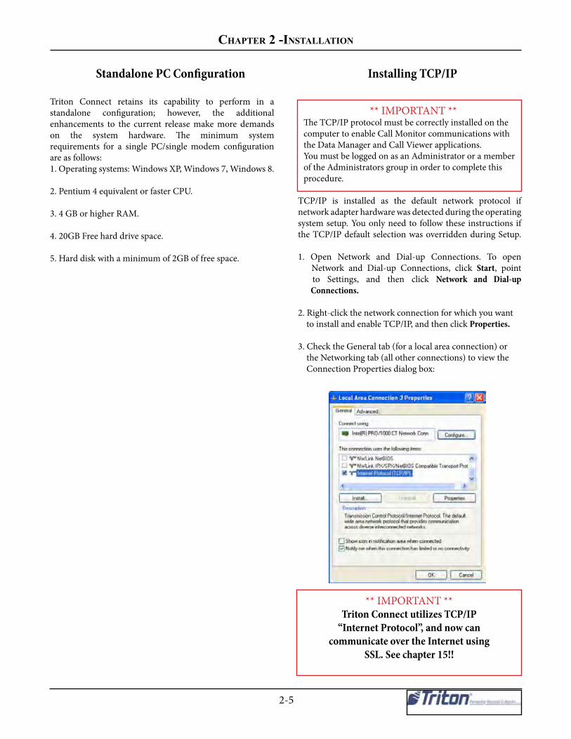
Standalone PC Configuration
Triton Connect retains its capability to perform in astandalone configuration; however, the additionalenhancements to the current release make more demandson the system hardware. The minimum systemrequirements for a single PC/single modem configurationare as follows:1. Operating systems: Windows XP, Windows 7, Windows 8.
2. Pentium 4 equivalent or faster CPU.
3. 4 GB or higher RAM.
4. 20GB Free hard drive space.
5. Hard disk with a minimum of 2GB of free space.
Installing TCP/IP
** IMPORTANT **The TCP/IP protocol must be correctly installed on thecomputer to enable Call Monitor communications withthe Data Manager and Call Viewer applications.You must be logged on as an Administrator or a memberof the Administrators group in order to complete this procedure.
TCP/IP is installed as the default network protocol ifnetwork adapter hardware was detected during the operatingsystem setup. You only need to follow these instructions ifthe TCP/IP default selection was overridden during Setup.
1. Open Network and Dial-up Connections. To open Network and Dial-up Connections, click Start, point to Settings, and then click Network and Dial-up Connections.
2. Right-click the network connection for which you want to install and enable TCP/IP, and then click Properties.
3. Check the General tab (for a local area connection) or the Networking tab (all other connections) to view the Connection Properties dialog box:
** IMPORTANT **Triton Connect utilizes TCP/IP
“Internet Protocol”, and now cancommunicate over the Internet using
SSL. See chapter 15!!

trItON CONNeCt USer MaNUaL
2-6
If Internet Protocol (TCP/IP) is already installed and theassociated checkbox is checked, click Cancel to exit.
If Internet Protocol (TCP/IP) is not in the list of installed components, then do the following:
a. Click Install. The Select Network Component Type dialog box appears:
b. Cick Protocal, and then click Add. The Select Network Protocol dialog box appears:
c. Click Internet Protocol (TCP/IP and then click OK)
4. Verify the Internet Protocol (TCP/IP) check box is selected, and then click OK to accept and exit.
REMOVING APPPLICATIONSIt may be necessary to use the CTRL-ALT-DELsequence to start the Task Manager utility, in orderto find and terminate any virus software or otherutilities that may be resident in memory. Someapplications must be disabled from the right side ofthe task bar.
DO NOT disable any system applications that arerequired for Windows to operate! If in doubt obtainthe assistance of your network administrator or otherPC support personnel!
POWER MANAGEMENT options, which includethe system standby and hard disk shut-off functions,SHOULD BE DISABLED! These options areaccessed through Control Panel/Display/ScreenSaver/Settings/Power Schemes. Set theoptions as indicated here: System Standby: NEVER Turn off hard disks: NEVERIMPORTANT: These functions must remaindisabled once Triton connect is installed!

Chapter 2 -INStaLLatION
2-7
For this release of Triton Connect, the installation process has been updated. The steps outlined below are for a standard single PC installation. An updated Windows installer and .Net Framework will be installed if required. SQL Server 2008 R2 Express is also included in the install. Note: these instructions are for performing a fresh Triton Connect installation on a single PC
1. To begin the installation process, run setup.exe.
Install Triton ConnectThis section will cover the actions you need to install Triton Connect on your network or standalone system. You must have a USB COMLOC device.
** IMPORTANT **The Triton Connect feature of the ATM must beENABLED and configured with the correct phonenumbers or TCP/IP information to allowcommunications with your Triton Connect hostsystem. See your ATM Operation Manual forinstructions on enabling the Triton Connect feature and entering the appropriate information.
2. After the updated windows Installer and .NET Framework installations are complete, if requirEd, a prompt will appear for installing SQL Server Express. Click Yes to install.
3. If the SQL Server Express detects any coMatability issues with your PC, they will be shown on this screen. Resolve any issues and restart installation.
4. Once the SQL server Express pre-requisites have been verified, read and accept the software license and click Next to continue.

trItON CONNeCt USer MaNUaL
2-8
5. On the next 6 screens, leave the default options selected and click Next.

Chapter 2 -INStaLLatION
2-9
6. Once SQL Server Express installation has completed successfully, click Close to continue with the Triton Connect installation.
7. When the Triton Connect installer continues, click Next to proceed.
8. Read and accept the license agreement and click Next.
9. Enter User Name and Organization (optional) and click Next.
10. Leave installation type as complete and click Next.
trItON CONNeCt USer MaNUaL
2-10
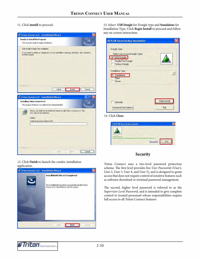
11. Click install to proceed.
12. Click Finish to launch the comloc installation application.
13. Select USB Dongle for Dongle type and Standalone for Installation Type. Click Begin Install to proceed and follow any on-screen instruction.
14. Click Close.
Security
Triton Connect uses a two-level password protectionscheme. The first level provides five User Passwords (User1, User 2, User 3, User 4, and User 5), and is designed to grant access that does not require control of sensitive features such as software download or terminal password management.
The second, higher level password is referred to as theSupervisor Level Password, and is intended to give completecontrol to trusted personnel whose responsibilities require full access to all Triton Connect features

Chapter 2 -INStaLLatION
2-11
Terminal Manager Access DEFAULT PASSWORDS
The default Supervisor password for Triton Connectis: CONNECT.The default User1 password is: TRITON.The default User2 password is: SOFTWARE.
Note that if Triton Connect was installed over anexisting copy of a previous version of the program,the User Level Password will remain as it was forthat version (see “Existing Passwords” below formore information).
Remember to change the default passwords as soon as possible after completing the installation!
EXISTING PASSWORDS
An existing Triton Connect password will not beaffected by the installation utility.
For versions of Triton Connect prior to 3 (Which used a single password), the existing password will be carried forward as the default User1/User2 Passwords.
The Supervisor Level Password will of courseassume its default value of CONNECT until modified.
When the Terminal Access Manager application is started for the first time, a password entry window appears:
At this point, you have the option of entering the TerminalManager as a User, or as a Supervisor. The level of accessyou’re granted depends upon the password entered here:User1, User2, User3, User4, User5, or supervisor password.
USER-LEVEL PRIVILEGESIndividuals with User1 or User2 access cannotperform the following actions:
1. Cannot change the Supervisor password.2. Cannot perform software downloads.3. Cannot alter certain terminal parameters(which ones depend upon the operatingsoftware installed in the terminal).
The above functions can only be performed bypersonnel with Supervisor access.
The User ID is now added to the title bar of the Terminal Manager window.

trItON CONNeCt USer MaNUaL
2-12
Changing the User Passwords
Because you’ll want to change the default passwordsimmediately after installing Triton Connect, you must initially enter the Terminal Manager using the Supervisor password. By doing so, you will be able to change the User1, User2, User3, User4, User5, and Supervisor passwords.
Enter the appropriate Supervisor password. When theTerminal Manager main window appears, click the Security option on the menu bar and select the Change User1 Password, Change User2 Password, Change user3 Password, Change User4 Password, or Change user5 Password option, as applicable. The applicable dialog appears:
Enter a new password in the top text box and press theENTER key on your keyboard. You’ll be prompted to verify the new password by entering it in the bottom text box.
Press the ENTER key after doing so. An OK button appears. click this button. The following message box appears:
Click the OK button to acknowledge the action. In a fewmoments, and if the password is successfully written to the COMLOC device, the following message will appear:
Click OK to dismiss the message box. The User password has been changed.
Changing the SupervisorPassword
Terminal Manager’s Security menu. The following dialog box appears:
Enter the current Supervisor password and press the ENTER key. You will be prompted to enter the new supervisor password. Enter the new password.
You will be prompted to verify the new password. do so and press ENTER. The following message appears:
Click the OK button to write the new password to the Comloc. A confirming message box appears.
Click OK to dismiss the message box. The Supervisor password has been changed.

Chapter 2 -INStaLLatION
2-13
Comloc ExpirationCall Monitor 6.0 has been update to expire according to the expiration on the Triton Connect Comloc.After expiration, the Call Monitor will not run until the Comloc expiration has been updated. The TerminalManager will continue to function as normal after expiration.
When the comloc will expire within 30 days, a notice will be shown both when the Call Monitor starts, or if theCal Monitor remains open for an extended period of time. A notice will be given once per day that expiration isnear.
Show notice when Comloc expiration is 30 days or less away
Notice that the comloc will soon expire
Notice that the comloc has expired
Show notice when Comloc has expired
Include Comloc Remote Update Client with install
The Comlocs will need the ability to be updated remotely to extend the expiration. To do this, the Comloc Remote Update Client utility is included in the Triton connect install. To update the Comloc expiration with this program will require contacting Triton technical Support.
Comloc Remote Update Client

trItON CONNeCt USer MaNUaL
2-14
Upgrade From Triton connect 5.X
Note: These instructions assume a single-PC installation upgrade from 5.x to this release of Triton Connect. These instructions also assume that the comloc driver is already installed.
1. Make a backup copy of the contents of the Triton Connect directory (optional).
2. Run setup.exe
3. Install SQL Server Express, if needed, using default settings.
4. At the inital Triton connect 6.0 screen, click Next.
5. After reading and accepting the license agreement, click Next.
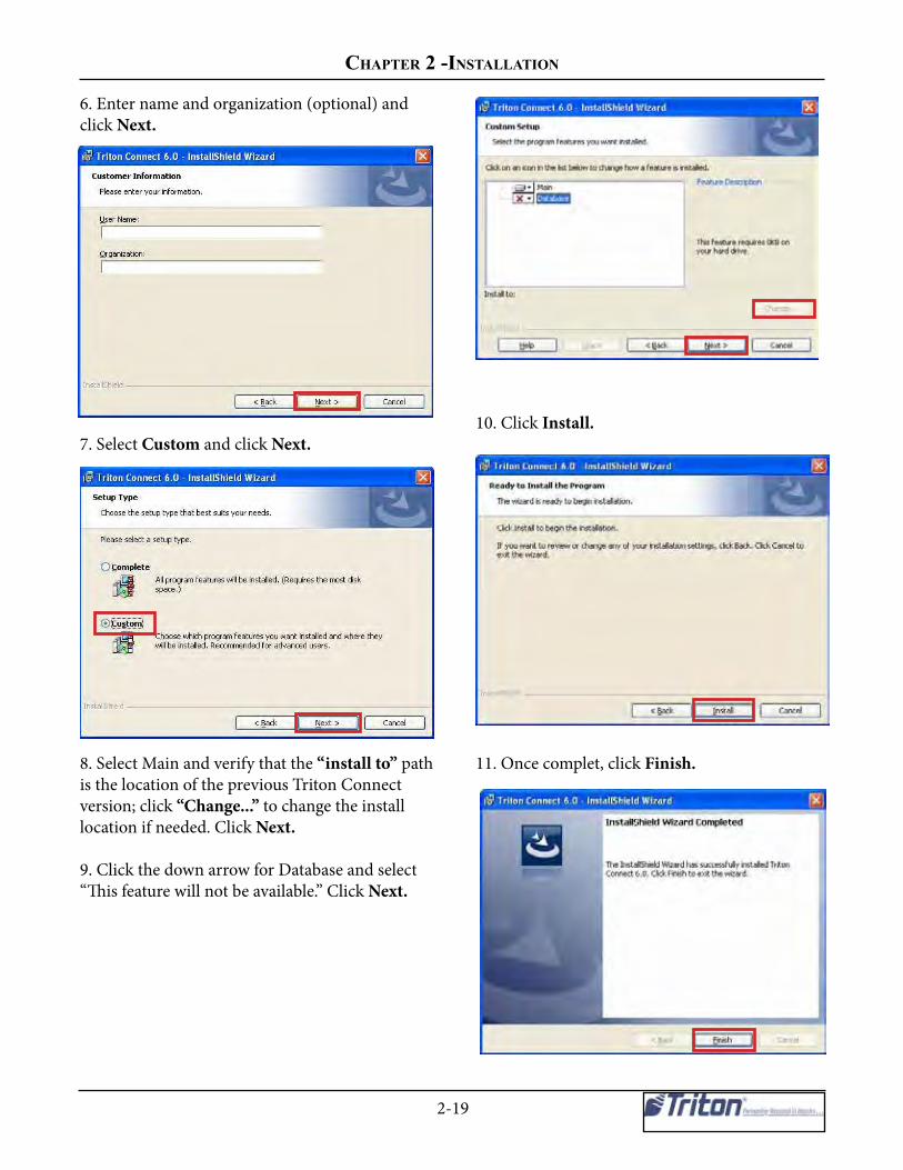
6. Enter name and organization (optional) and click Next.
7. Select custom and click Next.
8. Verify that the “install to” path is the location of the previous Triton Connect version; click “Change....” to change the install location if needed; click Next.

Chapter 2 -INStaLLatION
2-15
9. Click Install.
10. Once complete, click Finish.
11. Click Begin Install when comloc install utility opens.
12. Launch the Terminal Manager.
13. Click OK on message indicating that the SQL connection string has not been initialized.
14. On the Triton connect Database Migration Utility screen, click the Extensive Database Upgrade tab and verify the path to Triton connect 5.X database. Click Perform Upgrade.

trItON CONNeCt USer MaNUaL
2-16
4. On the Remove the Program window, Click Remove.
5. When the uninstall process is complete, click Finish.
6. Run setup.exe for the Triton Connect 6.0 SP3 and click Next.
1. Run setup.exe for currently installed Triton Connect 6.0
2. Click Next.
3. In the Program Maintenance window, click Remove, then click Next.
Upgrade From Triton connect 6.0
14. Once the database upgrade has completed, click the Migrate Journals tab and verify the TC_Main path. Click Begin.
15. Once Journal migration is complete, Triton Connect is ready to be used.

Chapter 2 -INStaLLatION
2-17
10. Click Install.
11. When installation is complete, click Next.
12. Click Finish.
7. After reading and accepting the license agreement click Next.
8. Enter name and organization (optional) and click Next.
9. Select Complete and click Next.

trItON CONNeCt USer MaNUaL
2-18
1. Make a backup copy of the contents of the Triton Connect Directory (optional).
2. Run setup.exe.
3. Install SQL Server Express, if needed, using default settings.
4. At the initial Triton Connect 6.0 install screen, click Next.
5. After reading and accepting the license agreement, click Next.
13. When the comloc install utility opens, Click Exit.
14. Launch the TC Database Utility and select the Extensive Database tab. Verify the database path and click Perform Upgrade.
15. Once the database upgrade is complete, close the TC Database Utility. Triton Connect is now ready to use.
Upgrade From Triton connect 5.X or 4.4
Chapter 2 -INStaLLatION
2-19
10. Click Install.
11. Once complet, click Finish.
6. Enter name and organization (optional) and click Next.
7. Select Custom and click Next.
8. Select Main and verify that the “install to” path is the location of the previous Triton Connect version; click “Change...” to change the install location if needed. Click Next.
9. Click the down arrow for Database and select “This feature will not be available.” Click Next.

trItON CONNeCt USer MaNUaL
2-20
15. When the Triton Connect Database Migration Utility is shown, navagate to the Extensive Database Upgrade tab, verify the path to the Triton Connect 5.X database, and click Perform Upgrade.
16. Once the database upgrade has completed, navagate to the Migrate Journals tab, verify the TC_Main path and click Begin.
17. Once the journal migration has completed, Triton Connect is ready to be used.
12. Click Exit when the comloc install utility opens.
13. Launch the Terminal Manager.
14.On the message indicating that the SQL connection has not been initialized, click OK.

Chapter 2 -INStaLLatION
2-21
Server Installation.
1. Run setup.exe.
2. When propmted to install SQL Server Express. Choose Based On if this or another version of SQL Server will be used. If installing this version, proceed though setup according to your environment.
3. For the Triton Connect setup type, select Custom and click Next.
Note: This installation is for a server that will host the database and the comloc. Client computers will run the Triton Connect application and connect to this server to access the databases and the comloc. The configuration for SQL server will vary depending on the operating environment and cannot be covered in this document. The version of SQL Server Express that is included with the Triton Connect installation can be used, or a full version of SQL Server can be used. This server may or may not run the Triton Connect application. These instructions assume a fresh installation of Triton Connect.
NOTE: Microsoft SQL Server will not successfully install on a disc that is either compressed or encrypted.
4. Verify/update the installation path and click Next.
5. click Install.

trItON CONNeCt USer MaNUaL
2-22
6. Once complete, click Finish.
7. For Dongle Type select USB Dongle.
8. For Installation Type select Server.
9. Click Begin Install and follow any on-screen instructions.
10. On the Install Success message, click Close.
11. Launch the Triton Connect Database Migration Utility from the installation location (TC Database Utility.exe.)
12. On the Migrate Journals tab, verify or change the TC_Main path and the SQL connection string and click Begin.
13. The server setup should now be complete.

Chapter 2 -INStaLLatION
2-23
5. Once complete, click Finish.
6. When the comlock install utility opens, click Client for Installation Type. Click Set Server (Optional) button in the Server Selection for Client section of the window.
1.Run setupu.exe
2. When propted to install SQL Server Express, choose No.
3. Leave installation type as Complete and click Next.
4. Click Install.
Client Installation
If another computer on the local network has been configured as a server for the databases and the comloc, additional computers may be added that connect to those same resources. The location of the TC Main database will need to be configured as a mapped drive and the SQL Server database must be accessible. The client must also be able to contact the server via port 4242 to use the comloc across the network.

trItON CONNeCt USer MaNUaL
2-24
10. Click OK on message indication the the SQL connection string has not been initialized.
11. When the Triton Connect Database Migration Utility is shown, update the SQL Connection String appropriately. Click Save.
12. Close the Triton Connect Database Utility
7. Click the Manual server selection by Name or IP Address radio button and enter the IP address of the comloc server. Click OK.
8. Click Begin Install and follow any on-screen instructions.
9. Launch the Terminal Manager.

Chapter 2 -INStaLLatION
2-25
16. Select the location of the database files and click OK.
17. Triton Connect should now be ready to use on the client computer.
13. Launch the Triton Connect Call Monitor.
14. Open the File menu and click Database Settings.
15. Click OK on the warning message.

trItON CONNeCt USer MaNUaL
2-26
Migrate Journal Archives to SQLNote: Any database that will be merged should be merged prior to using this feature. After merging and setup is complete, journal archives can be migrated at any time.
Follow these steps to migrate a journal archive to SQL:
1. Launch TC database Utility.exe.
2. Click the Migrate Journal Archive tab.
3. Enter or browse for the TC_Main.mdb database.
4. Enter or browse for the journal archive file.
5. Click Begin.

Chapter 2 -INStaLLatION
2-27
Combine Triton Connect Databases
This feature should only be used on databases from Triton Connect 5.x and above. Both the source and the destination databases should be from the same version of Triton Connect for compatibility purposes. The contents of the source database will be copied into the destination database.
Note: as part of the merge process, all journal data will be removed from the source and destination databases and those journals will be archived. These archives can later beimported to SQL, if desired, using the Migrate Journal Archive functionality.
To combine databases, perform the following steps.:
1. Close any Triton Connect components that may access either the source or the destination database.
2. Launch “TC Database Utility.exe” (located in the installation folder).
3. Navigate to the Merge Databases tab.
4. Enter or browse for the destination database location.
5. Enter or browse for the source database location.
6. Click Start.
7. Time to complete the merge will vary. Any feedback or errors will be shown in the lower half of the Triton Connect Database Migration Utility window.

trItON CONNeCt USer MaNUaL
2-28
THIS PAGE INTENTIONALLY LEFT BLANK

Chapter 3 - Call monitor

triton ConneCt User manUal
3-2
Introduction
The Call Monitor is a Triton Connect application that isused to configure and monitor Triton Connectcommunications.
Overview of Call Monitor Functions
The Call Monitor is an application that is used to configureand monitor connections to Triton Connect remoteterminals, using standard dial-up, TCP/IP, wireless, or VSATcommunication connections.The Call Monitor gives Triton Connect the ability to makecalls to terminals (call-out operations) and receive calls fromterminals (call-in operations).
The Call Monitor exercises overall control of all call activityby assigning each telephone line, TCP/IP connection orVSAT satellite link (as applicable) to an application calleda Call Processor. Each Call Processor will monitor andcontrol the calling activity of its associated connection. TheCall Processor will make calls to terminals, automaticallyanswer calls that come in from terminals, provideindications of the activity taking place during a call, andterminate the connection at the conclusion of a call.
Triton Connect is designed with a great deal of data-handlingcapacity. A single PC, running a single Call Monitor andusing 20 Call Processors, can handle in-coming and out-going calls for up to 1000 terminals. Only in extremely large scale operations would additional terminal-handlingcapacity be required, but in such cases Triton Connect isup to the task.
Primary functions of the Call Monitor include:
1. Call Processor startup and shutdown.
2. Management of communications between remoteterminals and the Triton Connect Host Installation.
3. Data Manager startup and shutdown.
4. Routing of Call Processor activity data to the CallViewer.
5. Coordination of Call Processor and Data Manageractivities.
6. Receiving calls if other parts of the program are shutdown.
Call Processor Startup and Shutdown
Once the Call Monitor is started, a 20-second countdownbegins. At the conclusion of the countdown all enabledCall Processors are started.
You may also start the Call Processors manually, either as agroup or individually.
Manage Communications between RemoteTerminals and the Triton Connect Host
Installation
Approximately every 15 seconds the Call Monitor readsthe entries in the Call List database. The Call List databaseshows when and to which terminal an out-going call is tobe made. When the scheduled time arrives for an out-goingcall, the Call Monitor assigns an available Call Processor tohandle the call.
Database ManagerStartup and Shutdown
The Data Manager processes the raw data received andstored by each running Call Processor, and saves theprocessed data to the appropriate Triton Connect database.The Data Manager is automatically started when the CallMonitor starts, and is shut down when the Call Monitor(and any active Call Proccessors) shuts down.
* NOTE *If the Database Manager is shut down while the Call Processors are running, the flat file data will not be processed until the Data Manager is restarted! This means that until the Data Manager is restarted and has processed the data, the databases and any reports generated from this data will not be current

Chapter 3 - Call monitor
3-3
Coordination of activities of the CallProcessors and Data Manager.
The Call Monitor assigns one or more available CallProcessors to monitor calls from terminals. As these incomingcalls are completed, the Call Monitor informs theData Manager, which processes the raw, received data andstores it in the applicable Triton Connect database.
Normally, a Call Processor that is receiving data from aterminal saves that data to a raw data file called a “flatfile.” This flat file is temporarily stored in a sub-folder ofthe Data folder in the Triton Connect installation directory(or other user-specified location). A sub-folder is createdfor each terminal for which data has been received.
The name of the sub-folder is the same as the Terminal IDof the applicable terminal.Once the flat file data is saved to a database the DataManager normally deletes the file. In some cases, however,you may wish to save this data for later review. The SaveFlat Files option (on the Call Monitor Diagnostics/DataManager Settings menu) allows you to do this.
*** CAUTION ***
DO NOT attempt to directly access the raw datafiles (flat files) created by the Call Processorsduring normal operation!
If you need to view this data, use the Save FlatFiles function to safely archive files for laterreview.
Periodically, the Call Monitor directs the Data Managerto “ingest” the flat-file data and save it to the appropriateTriton Connect database.
**** WARNING ****
If the Data Manager is shut down during normaloperation, the flat-file data will not be ingestedand stored in the Triton Connect databases!
Note: The Call Monitor communicates with the DataManager using a TCP/IP connection.
** IMPORTANT **
The TCP/IP protocol must be correctly installed onthe computer to enable Call Monitor-to-DataManager communications! The Call Monitor PC andworkstation MUST be on the same LAN or WAN toestablish a connection.
Route Call Processor activity data to the CallViewer application
The activity of each active Call Processor can be viewed atthe computer running the Call Monitor. However, inlocations where a network installation of Triton Connect isemployed, the computer running the Call Monitor may notbe readily accessible to operator personnel.
In such cases, the Call Viewer application can be run at anyoperator workstation that is running a legally-licensed copyof Triton Connect with Comloc, allowing personnel to viewthe activity of the Call Processors. The Call Monitor sendsCall Processor activity data to the Call Viewer. The CallMonitor communicates with the Call Viewer using a TCP/IPconnection.
Note: The Call Viewer function must be enabled in the CallMonitor for remote Call Viewers to access and display CallProcessor activity data. See description of the Enable CallViewer option for more information.
At the Call Monitor, Call Processor activity can be viewedin several ways:
1. Summary (single-line) status. The Call Monitor dialog offers a single-line status entry for each Call Processor.
2. Single Frame. Call Processor activity will be displayed in a frame that overlays the Call Monitor main dialog.
3. Separate Frames. The activity of each Call Processor will be displayed in its own dialog window. This is the default view.

triton ConneCt User manUal
3-4
Starting the Call Monitor
After Triton Connect has been installed, the Call Monitorapplication icon will be located in the Triton Connectapplication group. It can be accessed from the Start/Programs/Triton Connect menu in the Windows Task Bar.Click on the Triton Connect Call Monitor option to startit.
* NOTE *You may wish to place a shortcut to the Call Monitorapplication in the Windows Startup folder: This willallow the application to start automatically, once thePC running the program boots up.
When the Call Monitor is started, a 20-second countdownbegins:
At the conclusion of this countdown all enabled CallProcessors will be started.The countdown can be terminated prior to completion,using the Stop command button, or the Start commandbutton can be used to terminate the countdown and startthe Call proccessors immediatly.
Once the Call Processors have started, or the countdownhas been terminated, the Call Monitor main dialog appears:
A command button on the Call Monitor main dialog letsyou Start All Call Processors or Stop all Call Processors atonce.
Shutting down the Call Monitor
Click the Quit Program command button on the CallMonitor main dialog to shut down the program:
You can also select the Exit option from the File menu onthe Call Monitor menu bar.
* NOTE *When the Call Monitor shuts down, all associatedcomponents (Database Manager and any active CallProcessors) are also shut down!
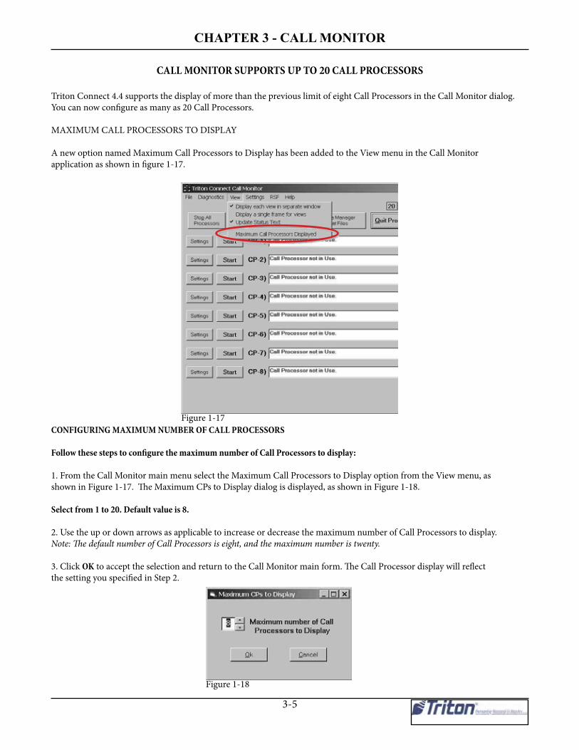
Chapter 3 - Call monitor
3-5
CALL MONITOR SUPPORTS UP TO 20 CALL PROCESSORS
Triton Connect 4.4 supports the display of more than the previous limit of eight Call Processors in the Call Monitor dialog.You can now configure as many as 20 Call Processors.
MAXIMUM CALL PROCESSORS TO DISPLAY
A new option named Maximum Call Processors to Display has been added to the View menu in the Call Monitorapplication as shown in figure 1-17.
CONFIGURING MAXIMUM NUMBER OF CALL PROCESSORS
Follow these steps to configure the maximum number of Call Processors to display:
1. From the Call Monitor main menu select the Maximum Call Processors to Display option from the View menu, asshown in Figure 1-17. The Maximum CPs to Display dialog is displayed, as shown in Figure 1-18.
Select from 1 to 20. Default value is 8.
2. Use the up or down arrows as applicable to increase or decrease the maximum number of Call Processors to display.Note: The default number of Call Processors is eight, and the maximum number is twenty.
3. Click OK to accept the selection and return to the Call Monitor main form. The Call Processor display will reflectthe setting you specified in Step 2.
Figure 1-17
Figure 1-18

triton ConneCt User manUal
3-6
Enabling/Disabling the Call ViewerThe Call Viewer is a separate Triton Connect application,which can be accessed from the Windows Start/Programs/Triton Connect menu, or from the Terminal Manager. Itlets a user access Call Processor status, via a TCP/IPconnection with the Call Monitor.To enable or disable the Call Viewer, open the CallMonitor’s Diagnostics menu. Note the Enable Call Vieweroption:
A check mark next to this option indicates the Call Vieweris enabled. When enabled, the Call Viewer application canestablish a TCP/IP connection with the Call Monitor in orderto receive Call Processor activity data. To disable the CallViewer, click the option to remove the check mark.
Configuring Database Settings** IMPORTANT **
The following instructions assume you arecomfortable navigating folders on a computerrunning Windows 2000 or Windows XP operatingsystem.
On a network installation, these settings should onlybe changed by IT personnel with appropriateadjustments made on workstations. All databasesMUST be in same folder.
In a standalone installation and most networkinstallations, the default settings do not need to bealtered. Incorrect settings WILL prevent correctprogram functionality.
on a network installation, these settings should only be changed bu IT personel with appropriate adjustments madeon workstations. All databases MUST be in same folder
Access the Database Settings option from the CallMonitor’s File menu.
Note: This option is only available if there are NO CallProcessors running.
This option brings up a Database Utilities dialog:
**** WARNING ****Before changing database settings, make sure allother Triton Connect programs (TerminalManager, Alarm Monitor, Call Viewer) have beenshut down!
This dialog lets you specify the location of the TritonConnect databases:
• Main (main.mdb) • Call List (callist.mdb) • Error List (errlist.mdb) • Reports (reports.mdb) • Reports Blank (rptblk.mdb) • Status (status.mdb) • Status History (stathis.mdb) • Terminal (termerr.mdb)
By default, the databases are stored in the Triton Connectdefault installation folder, but may be located in anotherfolder elsewhere on the network. If the databases are locatedsomewhere other than in the default location, use thisfunction to record the new location so that the TritonConnect applications can locate the databases.
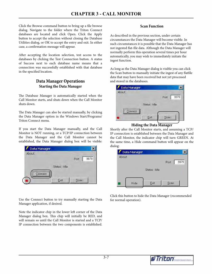
Chapter 3 - Call monitor
3-7
Click the Browse command button to bring up a file browsedialog. Navigate to the folder where the Triton Connectdatabases are located and click Open. Click the Applybutton to accept the selection without closing the DatabaseUtilities dialog, or OK to accept the entry and exit. In eithercase, a confirmation message will appear.
After accepting the location selection, test access to thedatabases by clicking the Test Connection button. A statusof Success next to each database name means that aconnection was successfully established with that databasein the specified location.
Data Manager OperationsStarting the Data Manager
The Database Manager is automatically started when theCall Monitor starts, and shuts down when the Call Monitorshuts down.
The Data Manager can also be started manually, by clickingthe Data Manager option in the Windows Start/Programs/Triton Connect menu.
If you start the Data Manager manually, and the CallMonitor is NOT running, or a TCP/IP connection betweenthe Data Manager and the Call Monitor cannot beestablished, the Data Manager dialog box will be visible:
Use the Connect button to try manually starting the DataManager application, if desired.
Note the indicator chip in the lower left corner of the DataManager dialog box. This chip will initially be RED, andwill remain so until the Call Monitor is started and a TCP/IP connection between the two components is established.
Scan Function
As described in the previous section, under certaincircumstances the Data Manager will become visible. Insuch circumstances it is possible that the Data Manager hasnot ingested flat-file data. Although the Data Manager willnormally perform this operation several times per hourautomatically, you may wish to immediately initiate theingest function.
As long as the Data Manager dialog is visible you can clickthe Scan button to manually initiate the ingest of any flatfiledata that may have been received but not yet processedand stored in the databases.
Hiding the Data ManagerShortly after the Call Monitor starts, and assuming a TCP/IP connection is established between the Data Manager andthe Call Monitor, the indicator chip will turn GREEN. Atthe same time, a Hide command button will appear on thedialog:
Click this button to hide the Data Manager (recommended for normal operation).

triton ConneCt User manUal
3-8
* NOTE *The Data Manager is normally “hid” upon starting theCall Monitor. You can initiate the Data Manager’s flatfilescan from the button available in the Call Monitor.
Use this option to shut down the Data Manager. Once shutdown, this option changes to “Restart Data Manager” andcan be used for that purpose, as described in the next section.
**** WARNING ****If you shut down the Database Manager, theTriton Connect databases may not be updatedwith the data received from terminals. DataManager scan results are shown in a Callprocessor window - defaulting to CP1.
Note: If the Call Monitor terminates without notifying theData Manager, the Data manager will become visible,allowing you to use the Exit button to close the dialog.
Restarting the Data Manager
If the Data Manager has been shut down, or is not currentlycommunicating with the Call Monitor, you can restart itusing the Restart Data Manager option on the CallMonitor’s File Menu.
Shutting Down the Data Manager
Access the Shutdown Data Manager option from the CallMonitor’s File menu. You can manually shut down the DataManager using an option on the Call Monitor File menu.
Configuring Call MonitorTCP/IP Settings
Access the TCP/IP Settings option from the Call Monitor’s Settings menu:
The Call Monitor communicates with various TritonConnect components using the TCP/IP communicationsprotocol. The connection with each component requires aPort Number. The Call Monitor creates a default PortNumber for each connection; however, your networkadministrator can configure the Port Numbers manually, ifrequired to avoid conflicts with existing network settings.
Note: TCP/IP settings can be viewed now with CallProcessors running. They can only be changed if all CallProcessors are stopped.
** IMPORTANT **In a standalone installation and most networkinstallations, the default TCP/IP settings do notrequire alteration. Incorrect settings WILL preventcorrect program operations.
Selecting this option brings up the TCP/IP Settings dialog:

Chapter 3 - Call monitor
3-9
The dialog lets you enter or modify TCP/IP port entries forthe following connections:
• Call Monitor-to-Data Manager.
• Call Monitor-to-Call Viewer.
• Inbound from Terminals. This port number is requiredby terminals using TCP/IP communications to contactthe Triton Connect host installation. The port numberis entered at the terminal, and serves as the equivalentof a Triton Connect “phone number.”
* NOTE *The TCP/IP address of the computer running theCall Monitor application is also displayed in the TCP/IP Settings dialog. This address must be entered atthe Call Viewer, along with the Call Monitor-to-CallViewer port number, to ensure correct Call Vieweroperation.
First Journal TimeoutIn order to enable and configure for an extended amountof time while retrieving the first journal record, the userselects this option from the Call Monitor Settings menu.
When selected, the following screen is displayed. Thisallows setting the amount of delay time allowed whenreceiving the first journal record. You must enable thisoption if used.
Configuring Terminal OriginatedCall Expiration Time
* NOTE *The Terminal Originated Call feature is onlyapplicable to terminals that also support the feature.
Access the Terminal Originated Call Settings option fromthe Call Monitor’s Settings menu:
This option is only available when there are NO CallProcessors running. Selecting this option brings up thefollowing dialog:
The dialog lets you specify a Time Duration for TerminalOriginated Calls. This duration can be specified in intervalsof hours, days, months or years. Change the settings asneeded and click OK to accept.
The life of each Terminal Originated Call entry in the CallList is monitored from the time of creation. When the interval determined by the Time Duration setting expires, the entry is removed from the Call List.

triton ConneCt User manUal
3-10
Adding and Removinga Call Processor
Access the Add a Call Processor and Remove a CallProcessor options from the Call Monitor’s Settings menu.
Add a Call Processor
Each time you select this option a Call Processor is addedto the available list. The maximum allowable number ofCall Processors is 20. If necessary, the Call Monitor dialogwindow can scroll to provide access to any additional CallProcessors.
Remove a Call Processor
Each time you select this option a Call Processor is removedfrom the available list. The minimum allowable number ofCall Processors is one.
Enabling/Disabling ExtendedStatus Text Updating
Access the Update Status Text option from the CallMonitor’s View menu:
A check mark next to this option indicates it is active. Whenactive, extended status information (in addition to thesummarized information that normally appears) will bedisplayed in the single-line status view on the Call Monitormain dialog:
Viewing Call Processor Activityin a Separate Window
Access the Display each view in separate window optionfrom the Call Monitor’s View menu:
A check mark next to this option indicates it is active. Whenactive, whenever the View command button for a CallProcessor is clicked, the activity of that Call Processor willbe displayed in a separate status window. The default is“Display in separate window”.

Chapter 3 - Call monitor
3-11
Viewing Call Processor Activityin a Single Frame
Access the Display a single frame for views option fromthe Call Monitor’s View menu:
A check mark next to this option indicates it is active. Whenactive, whenever the View command button for a CallProcessor is clicked, the activity of that single Call Processorwill be displayed in a window that replaces the normal CallMonitor dialog
Note: If the separate window and single frame options areboth enabled, both views will be presented when the Viewbutton is clicked.
Displaying Hex Data on Screen
*** CAUTION ***DO NOT use this option unless directed to do so bytechnical support personnel! This option should onlybe used for diagnostic purposes!
Access the Display data on screen option from the CallMonitor’s Diagnostics menu:
A check mark next to this option indicates it is active. Whenactive, this function enables the display of all the transmittedand received data handled by each Call Processor port, inhex code. This data will appear in the applicable CallProcessor’s activity window.
Capturing Call Processor Datato a File
*** CAUTION ***This option can create very large files! Do notuse this option unless directed by technicalsupport personnel!
Access the Capture to file option from the Call Monitor’sDiagnostics menu:
A check mark next to this option indicates it is active. Whenactive, a data file for each Call Processor is created in theTriton Connect program folder (output1.DAT, output2.DAT,etc.).
This data file is used to record a copy of the associated CallProcessor’s activity display. The contents of the data filecan be viewed with a text editor or word processor program.
Redirecting the Call ProcessorData Location
* NOTE *This option should not be used without a thoroughunderstanding of the program. There is no furtherinformation available.

triton ConneCt User manUal
3-12
Reserving a Call Processorfor Incoming Calls
Access the Reserve a CP for incoming calls option fromthe Call Monitor’s Settings menu:
Select this option to reserve one of the available (andenabled) Call Processors for exclusive use for in-comingcalls. This option may be useful in very busy installations,when it seems that some terminals are having problemsreaching an available Call Processor.
Configuring the CommunicationsTimeout Duration
Access the Communications timeout option from the CallMonitor’s Settings menu:
Use this option to select the time (in seconds) the CallProcessor will wait before reporting a failed callback attemptfrom a remote terminal. The available delay values are 10,20, 40 and 80 seconds. A checkmark shows the value that isthe currently selected. The default value is 20 seconds.
In most cases the default value of 20 seconds is sufficient;however, in some international locations dial-upconnections may take longer to complete, requiring a longertimeout delay setting to prevent excessive failed callreports.
Saving Flat Files
Access the Data Manager Settings option from the CallMonitor’s Diagnostics menu. A sub-menu provides accessto the Save Flat File option:
A check mark next to this option indicates it is active.When active, the Data Manager will save the flat file datasaved by each Call Processor instead of deleting it afteringesting the data. Each file will be saved in a separatefolder, and will be given a name that consists of the year,month and day on which the terminal data was received,as in 20041101.
The data can be viewed with a text editor or word processorprogram. However, it is stored in Hex, not readable Textformat.
Logging Data Manager Activityto a File
Access the Data Manager Settings option from the CallMonitor’s Diagnostics menu. A sub-menu provides accessto the Enable Logging to File option:
A check mark next to this option indicates it is active.When active, the Data Manager will log its activity to thefile DM.log in the Triton Connect application folder. Thislog can be opened and viewed using a text editor such asNotepad or other word processing program.

Chapter 3 - Call monitor
3-13
Output to CSV Files
Access the Data Manager Settings option from the CallMonitor’s Diagnostics menu. A sub-menu provides accessto the Output to CSV (Comma Separated Value) Files option:
A check mark next to this option indicates it is active. Whenactive, the Data Manager will save incoming journal data toa folder named CSV. A file will be created in the CSV folderfor each terminal that sends journal data.
The data will be saved in (CSV) format. This is a comma-delimited format that is designedto be easily imported into applications such as spreadsheetand database programs. Note: The CSV folder will becreated in the same folder location as the Data folder.
Output to Tape Format Files
Access the Data Manager Settings option from the CallMonitor’s Diagnostics menu. A sub-menu provides accessto the Output to Tape Format Files option:
A check mark next to this option indicates it is active. Whenactive, the Data Manager will save incoming journal datato a folder named Tape. A file will be created in the Tapefolder for each terminal that sends journal data.
The data will be saved in the same report-style format usedby the terminal to print journal reports.
Note: The Tape folder will be created in the same folderlocation as the Data folder.
Export JournalsAccess the Data Manager Settings option from the CallMonitor’s Diagnostics menu. A sub-menu provides accessto the Export Journals option:
A check mark next to this option indicatets it is active. Whenactive, the Data Manager will export journals into another database named ExpJrnls.mdb. in an expanded format.
Selecting a Call ProcessorSettings Dialog
Access the Call Processors option from the Call Monitor’sSettings menu:
Selecting this option calls up a Call Processor Settingsdialog. From this dialog you can select an available CallProcessor to configure. Only Call Processors that arecurrently stopped can be selected using this option. Youcan also access the Call Processors by selecting “Settings”for individual Call Processors.
See the section, Configuring Call Processor Settings, forinformation on viewing and changing Call Processorsettings.

triton ConneCt User manUal
3-14
Starting a Call ProcessorEach Call Processor entry on the Call Monitor main dialoghas a Start button:
If the Call Processor has been enabled and properlyconfigured you can start that Call Processor by clicking theStart button for that Call Processor.
Viewing Call Processor Activity
In addition to single-line status (available from the CallMonitor main dialog), you can click the View button todisplay activity data for any Call Processor:
When clicked, the activity of the Call Processor will bedisplayed according to the current viewer settings: separatewindow, single frame, or both.
If the Display each view in separate window option hasbeen selected on the Call Monitor’s View menu, the activityof that Call Processor will be displayed in a separate statuswindow:
If the Display a single frame for views option has beenselected on the Call Monitor’s View menu, the activity ofthe Call Processor will be displayed in a window thatreplaces the normal Call Monitor dialog:
Either type of viewing window provides two commandbuttons:
• Close. Close the viewer window. If a Single Frame, return to the default Call Monitor dialog window.• Pause/Resume. Pause or Resume the operation of the Call Processor.
Configuring Call Processor Settings
The Call Processor Settings dialog allows you to enableand configure any available Call Processor.For dial-up communications, you must have one availableanalog modem and phone line for each Call Processor youwish to configure.
For TCP/IP communications, up to twenty (20) TCP/IPconnections can be used on one (1) connection
** IMPORTANT **Only Call Processors that are currently NOT runningcan be selected!
You can use either of the following methods to bring up aCall Processor Settings dialog:
• On the Call Monitor main dialog, click the Settings command button for the Call Processor you want to configure. • Select the Call Processor option from the Settings menu on the Call Monitor menu bar When the dialog appears, a drop-down list lets you select the specific Call Processor you want to configure.

Chapter 3 - Call monitor
3-15
The Call Processor Settings dialog appears:
Use the dialog to enable and configure the settings for anyavailable Call Processor. The various configuration settingsare covered in the following sections.
Call Processor (1 to 20)
This is a drop-down list of the available Call Processors.The currently selected Call Processor is shown in the list,but you can select another Call Processor if you wish. Notethat only Call Processors that are currently NOT runningwill be displayed in the drop-down list.
Enable Call Processor
Place a check in this checkbox to enable the Call Processorcurrently selected in the drop-down list. Once enabled (andafter any additional required configuration settings havebeen made), the Call Processor can be started.

triton ConneCt User manUal
3-16
Connection Type
This is a drop-down list that lets you pick the type ofconnection this Call Processor will use for terminalcommunications:
1. Phone Line. When this option is selected you mustselect an available modem in the Modems Availabledrop-down list. The selected mode name will appear inthe Modem Selected text box. The Call Processorcannot be started unless a modem selection has beenmade!
2. VSAT X.121. When this option is selected you mustselect an available COMM port in the Comm PortSelected drop-down list. This Comm port is connectedto the VSAT communication device.
3. TCP/IP. When this option is selected the Call Processorwill use the IP Address and Port settings in the Call Listwhen contacting a terminal with a TCP/IP connection.
4. Radio Pad. When this option is selected, you selectthe Comm port the modem is connected to for the radioPad device
CONNECTION TYPES
The Dial-up phone line connection type is used withall Triton ATMs except RL/FT5000 XP/PC-basedunits.
The TCP/IP connection type is used with ATMs thatare either TCP/IP capable (RL/FT5000/RT2000) orhave the (optional) External Ethernet assemblyinstalled (91XX/97XX/96XX).
The VSAT connection type is used with ATMs thatsupport Very Small Aperture Terminal (VSAT)satellite-based communications. VSAT supports awide range of communications protocols.
Communication Direction
A series of option buttons lets you choose the direction typeof calls this Call Processor will handle:
1. In. If this option is chosen the Call Processor will handlein-bound calls ONLY.
2. Out. If this option is chosen the Call Processor willhandle out-bound calls ONLY.
3. Both (In and Out). If this option is chosen the CallProcessor will handle both in-bound and out-boundcalls. Note: This option is the default and for normaloperation does not need to be changed.
4. Alarms Only. If this option is chosen, the Call Processorwill handle only in-bound calls that carry terminal alarmstatus ONLY.

Chapter 3 - Call monitor
3-17
Dial Modifier
This text box is available when the Phone Line ConnectionType is selected. Use this box to enter any special dialingcodes that may be required when dialing out from yoursystem, such as a dial-out prefix of ‘9.’
Modem Selected
This text box is available when the Phone Line ConnectionType is selected. Shows the currently selected modem thisCall processor will use when placing Phone Line calls.
Modems Available
This drop-down list is available when the Phone LineConnection Type is selected. Provides a list of availablemodems
** IMPORTANT **DO NOT configure more than ONE Call Processorfor each available modem!
Modem Settings
This button allows access to select modem settings.
General: Allows user to select Call and Data Connectionpreferences.
Advanced: Allows user to Terminal Window options andmodem hardware settings.
Note: The default settings are normally correct.

triton ConneCt User manUal
3-18
Comm Port Selected
This text box is available when the VSAT connection typeis selected. Shows the currently selected PC COM portconnected to the VSAT communications hardware.
Prev
Click this command button to access the settings for theprevious available Call Processor.
Next
Click this command button to access the settings for thenext available Call Processor.
Save
Click to save the settings changes for the currently selectedCall Processor and remain in the Settings dialog.
OK
Click to save the settings changes for the currently selectedCall Processor and exit the settings dialog.
Cancel
Exit without making any changes to the Call Processorsettings.
Retry Calls with wrong TID
There is no error correction during the challenge/responseportion of the communications between the terminal andTriton Connect. Sometimes data is changed duringtransmission by interference. In some of these cases theTID is corrupted. So instead of deleting the call, this optionhas Triton Connect assume there are comms problems andwill keep the call list entry.
Short Challenge/Response Timeout
During the beginning of the communications, sometimesthe first packet is sent from Triton Connect before theterminal is ready to receive it. There is a default timeout of20 seconds between packets. This option sets the timeoutto 5 seconds for the first beginning packet attempt. It thenincrements to 10 seconds for the second attempt, then 15for the third, and so on.

Chapter 3 - Call monitor
3-19
Short Modem Initial Timeout
When starting Triton Connect Call Monitor and CallProcessors, the Call Processors are put into the “Waitingfor call” state. The time elapse for this has a default of 80seconds. This is to prevent collisions with inbound callswhen starting/restarting the call processors and there areoutbound calls to be made. This option (basically for
testing) reduces this delay time to 10 seconds
Force old ISO Format (Z-180s)
This option forces Triton Connect to send the ISO numbersin the old format (100-10 digit ISO #s) even though theterminal indicated it supported the X-scale format.
Cycle Call Processors (new)
This new option allows you to schedule Cycling of all callprocessors (stopping and restarting) at a specific interval.This may be applicable for larger system users that may be
having communication issues.

triton ConneCt User manUal
3-20
RSF- Remote Status Feed
This new feature allows 3rd party interface. It sends status information to 3rd party via TCP/IP. Select RSF on the CallMonitor main menu bar to access the settings. This will bring up the following screen:
Enable/DisableRemote Status Feed
IP Address of Remote StatusMonitor when connected IP Port TC listens for
connection with Re-mote Status Monitor
Protocol limits the use of only 10characters of the Terminal ID

CHAPTER 4- CALL MONITER
Chapter 4 - terminal Setup

triton ConneCt uSer manual
4-2
Introduction
In this chapter we will cover the functions that enable youto create, modify, delete, and view terminal records in theTriton Connect main database. This is accomplished throughthe Terminal Manager application. In addition, other optionsrelated to terminal setup, database management, andautomatic alarm message transmision are also managedthrough the Terminal Manager
** IMPORTANT **Never attempt to access the Triton Connect databasedirectly or alter the information other than throughthe Terminal Manager. You may cause the programto become inoperable!
We’ll begin with the basic terminal record managementfunctions for adding, deleting, modifying, and viewingterminal records.
Adding a New TerminalPurpose
Each terminal you wish to manage using Triton Connectmust first be loaded into the terminal database. This willprovide Triton Connect with the information it needs tocontact the terminal, and to identify the terminal and itsassociated data in the database.
* NOTE *If a terminal is not in the database, the Call Processorwill receive parameters, error information, andjournals. However, the data will not be put into thedatabase. Terminals must be added to the databasebefore you can call them. The Data Manager willdisplay a message when there is data for a terminalnot in the database.
Accessing the Add New Terminal Function1. Start the Terminal Manager application.
2. From the Setup menu, select the Add New Terminal option. The Add New Terminal window appears:
As you can see, the Add New Terminal function isessentially a data entry form for the Triton Connect database.The screen consists of all those fields that make up adatabase record. Let’s briefly cover the fields and other inputareas on this form.
ABOUT DATA-ENTRY FIELDS1. The Terminal ID and Terminal Phone Number/ IP Address fields must be filled in before the new terminal record can be saved.
2. All Terminal ID field entries are automatically converted to uppercase when the entry is saved to the database
Terminal IDEnter the TERMINAL NUMBER that has been assigned tothe terminal. This number is assigned and entered into theterminal during physical installation by your processor orservice provider.
** IMPORTANT **Make sure the Terminal ID you enter exactly matchesthe value assigned to the Terminal Number parameterat the terminal! You may use numbers, letters, andmost special characters to form the ID. You may enterup to 16 characters.
If a terminal at a location is replaced with a terminalof a different type using the same Terminal ID (forinstance, replacing a Model 9600 with a ModelRL5000), before contacting the terminal for the firsttime to retrieve parameter and journal data, thecurrent information MUST be archived. Otherwise,information for the new terminal or the formerterminal may not display correctly

4-3
CHAPTER 4- TERMINAL SETUP
Location Name
This is the name of the establishment where the terminal issetup and operating.
Address
This will normally be the address of the establishmentidentified under Location Name.
Contact 1/2
There are two fields available to enter the names ofindividuals or organizations that can act as a point of contactat the address specified above. The use of these fields isoptional.
City, State, Zip Code
Enter the requested information to complete the addressdata.
Terminal Phone # / IP Address
If the terminal is connected to the standard telephone system,enter the complete number of the telephone line that servicesthe terminal at the operating location. If the terminal isconnected to a VSAT earth station, enter the VSAT contactnumber for the terminal, which will be provided by yourVSAT service provider or processor organization.
The IP ADDRESS will be used to communicate withterminals connected to the TCP/IP or CDMA (wireless)network. It is provided by your host processor organizationor service provider. The address is a two-part entry. Thefirst part of the address consists of a sequence of four groupsof numbers in typical IP Address format. Each number groupcan be up to three digits long, and each group is separatedby a period (dot character), as in this example:123.321.01.99.
The second part of the IP ADDRESS consists of up to aFIVE-digit Port Number, which is described next.
Port NumberThe Port Number is a sequence of one or more numbers,provided by your host processor organization or serviceprovider, which provides additional data-routinginformation to enable Triton Connect to communicate withthe selected terminal on the TCP/IP or wireless network
User 1-5
These five fields can be used to add additional identifyinginformation to the database record for the terminal. Usedin conjunction with the Filters capability of Triton Connect,User Fields can be a powerful means of organizing andgrouping terminals, especially if a many terminals are beingmanaged. Their use, however, is optional.
If you wish to change the default labels for the user fields,use the Configure User Fields function (see the ConfigureUser Fields topic later in the chapter).
NotesThis is a text-entry box that allows you to enter anyadditional information you may wish to about the terminal,such as special requirements, additional contact information,etc.
Journal Clearing
Select Manual if the terminal operator at the operatinglocation will be manually clearing the terminal’s ElectronicJournal. If Automatic is chosen, then Triton Connect willinitiate journal clearing whenever the journal has beensuccessfully downloaded by the Get Journal Data function(covered in a later chapter).
JOURNAL CLEARINGCAUTION: If Journal Clearing is set to Manual,and the Electronic Journal in the terminal has notbeen cleared before the next Get Journal Datacommand is issued, the old journal entries will stillbe present in the journal. These entries will bereceived during the download and stored in thejournal database, duplicating the entries alreadystored there!
IMPORTANT: The Electronic Journal cannot holdan unlimited number of entries. The 8-bit machines(9100/96XX/97XX/Mako/SS) can hold at most 2045journal entries. The 32-bit machines (FT/RL/RT/9800)can hold 32,768 entries. If the journal size limit isreached, the terminal will enter an OUT OF SERVICEcondition and will remain in that state until the journalis cleared!

triton ConneCt uSer manual
4-4
ATM Connection Type
Select the speed of the modem in use by the terminal or thecorrect connection type.
Time Zone
Enter the time zone in use at the terminal’s operatinglocation.
Use Daylight Savings Time
If Daylight Savings Time is used at the terminal’s operating location, make sure the box is checked.
Save
When all the required data has been entered, click the Savebutton. The program will check to make sure the terminalID does not duplicate any existing ID in the database. If itdoes, you will be prompted to change the Terminal ID to aunique identifier. If no duplicate ID exists, the operationwill continue.
Next, you will be given an opportunity to enter the EPROMAccess Code for the terminal. The following dialog boxwill be displayed:
If you wish to enter the EPROM Access Code at this time,enter the code and click the Enter button. For securityreasons the code characters you enter will be displayed asasterisks, so you will be prompted to enter the code a secondtime, to verify it was entered correctly. If you choose toleave the EPROM Access Code entry blank for now, clickthe Skip Step button.
* NOTE *For RL/FT5000, RL/ RT2000 model ATMs, the TritonConnect access code should be assigned at theterminal and entered as the EPROM Access Code
EPROM FUNCTIONS
The term “EPROM” is an acronym for “EraseableProgrammable Read-only Memory.” The terminaluses an EPROM “chip” to store “firmware” (data andprograms required for terminal operation).
The EPROM chip provides a number of importantcapabilities, such as:
1. Ability to perform certain terminal hardware tests.
2. “Bootstrap” code which assists in loading the main terminal operating software during the Software Download procedure (8-bit units).
3. Routines that provide low-level access to to the terminal hardware.
The EPROM operates in a fashion similar to the BIOSin a Personal Computer.

4-5
CHAPTER 4- TERMINAL SETUP
Deleting a TerminalPurpose
Use this function to remove terminal records from thedatabase.
** IMPORTANT **Once a terminal is deleted all information concerningthat terminal is removed from the database, includingany Journal related to the terminal.
Accessing the Delete Terminal Function
1. Start the Terminal Manager application.
2. From the Setup menu, select the Delete Terminal option. The Delete Terminal window appears:
Selecting a Terminal for Deletion
In order to delete a terminal you must first locate theterminal’s record in the database. There are a number ofways to do this. If you know the ID of the terminal, theeasiest method is to select it directly from the Terminal IDdrop-down list:
Another method is to use the search facility. To do this,click the Search button:
A prompt appears (in red), instructing you to select a fieldto search:
When you click the mouse cursor on the field you want tosearch, the following dialog box appears:
What you enter here depends on your knowledge of thekinds of entries contained in the field. For example, assumeyou have clicked on the Terminal ID field. You want tolocate the record that contains a terminal ID of Test1. Enterthe text Test1 in the search box and click OK:
The record data for Test1 will appear in the applicable fields.If the search function cannot locate a record that containsthe exact text you entered in the selected field, the followingmessage will be displayed:

triton ConneCt uSer manual
4-6
A third method for selecting terminals involves the use offilters, which enable you to display only terminal recordsthat fit a defined specification. The use of filters will becovered in detail in a later chapter.
SELECTING TERMINAL ID’s
Pressing the first letter of a Terminal ID willautomatically select the first ID in the listing thatstarts with the chosen letter. Typing additional lettersfurther refines this selection process, enabling youin many cases to quickly select a Terminal ID byentering only a few characters.
Deleting a Terminal
Once the data for the selected terminal is displayed, checkit to make sure this is the terminal you really want to delete.If it is, simply click the Delete button:
A confirmation message appears:
Click Yes to continue with the delete action. Deletion isconfirmed by this message:
BULK DELETE TERMINALSThis new feature enables you to delete multiple terminalsat one time.
ACCESSING THE BULK DELETE TERMINALS DIALOGTo access the Bulk Delete Terminals dialog, select theBulk Delete option from the Terminal Manager Setupmenu. The Bulk Delete Terminals dialog appears.
IMPORTING TERMINALS VIA INPUT FILEOn the bulk delete dialog there is a button named SelectInput File button. This button allows you to browse the PCfile system for an input file. When you locate and open aninput file, the bulk delete application will evaluate the inputfile using the following criteria:- The file must be a simple text file, with an extension of.TXT..- The contents of the file must be a list of Terminal IDs.- There should be no more than one Terminal ID per line.- Each Terminal ID must be no longer than a maximum of 17 characters in length.

4-7
CHAPTER 4- TERMINAL SETUP
IMPORTANT: If the bulk delete application has problemsprocessing the text file (i.e., the text file does not containany data, etc.), the application will display the warningmessage shown in Figure 1-7.
The bulk delete application will compare the input file tothe current database. If the application is unable to find acorresponding match in the database for each terminal inthe input list, it will list the invalid Terminal ID in a dialogbox (see Figure 1-8).
DELETING DATAWhen the user presses the Clean button on the BulkDelete Terminals main window, the application will use thelist of valid Terminal IDs from the input file to locate anddelete the associated data (i.e., tables, records, andfolders) from the TC_Main database.Note: The .###. following the names of the first 3 tablesdenotes that there are multiple tables with the samename. Each one of the tables is associated with aparticular terminal ID.DATABASE TABLE DELETION TARGET
TC_MAIN ADDATA### Entire Table J OURNAL### Entire Table PARAMETERS### Entire Table CONFIGURE Record matching specific ID STATUS Record matching specific ID FeatureSettings Records matching specific ID ScheduleReboot Records matching specific ID ExtErrorInfo Records matching specific ID EMVData Records matching specific IDEMVParameterDataAppList Records matching specific IDEMVParameterDataBoolean Records matching specific ID LCCassStructure Records matching specific ID LCDayStructure Records matching specific ID LCEEValues Records matching specific ID SurchargeScreen Records matching specific ID
CONFIRMING COMPLETIONOnce the bulk delete application has successfully deletedall of the data related to the targeted terminals, it willdisplay a message box to confirm that it has completedthe task (see Figure 1-9).
It is recommended that you run the Repair/Compact/Replace Database function after performing a bulk deleteoperation. This option is located under the TerminalManager File menuIf the bulk delete application runs into a problem processingthe Terminal IDs (i.e., no data found or database errorsencountered), the application will annotate these errors in alog file (see the next section, Logging Activity).
Loging activityThe Bulk Delete application will keep a log file of all of itsactions in the current directory (typically the TritonConnect installation directory). The log file will be titled.Delete.log..

triton ConneCt uSer manual
4-8
Modifying a Terminal Record
PurposeUse the Modify Terminal function to make changes to aterminal record that has already been created and stored inthe database.
Accessing the Modify Terminal Function
1. Start the Terminal Manager application.2. From the Setup menu, select the Modify Terminal option. The Modify Terminal window appears:
Selecting a Terminal Record to ModifyRefer to the previous section (“Deleting a Terminal”) fordescriptions of the various methods for selecting a terminal.
Modifying a Terminal RecordOnce you’ve selected the record you want to modify andthe terminal data is displayed, it is a simple matter to alterthe information in a given field. Because these fields weredescribed in the section on Adding Terminal Records, wewon’t go into them again here. However, there are a numberof other features specific to this function that we do need tocover: Reset, Update, Options, and Change EPROMPassword.
Reset
If you change your mind about a modification to the record,and the Update button has not been pressed, you may clickthe Reset button to clear any changes and restore the fieldsto their original contents.
UpdateOnce you’re satisfied with any changes you’ve made to thecontents of the data entry fields, click the Update button tosave the changes to the underlying database.
Change EPROM Password
Clicking the Change command button brings up thefollowing dialog box:
Use this data entry box to initially enter or modify the copyof an existing EPROM Access Code in the database. Notethat the entry you make here is stored in the database anddoes not alter the Access Code at the terminal. It will beused to gain access to the terminal for remote softwaredownload purposes.
Options
Click this command button to access the Modify StatusMessage Settings for the currently selected terminal. Seethe Modify Status Message Settings topic later in thechapter

4-9
CHAPTER 4- TERMINAL SETUP
Viewing Terminal SetupPurpose
Use this function to view the data for a selected terminal inthe database.
Accessing the Terminal Setup Function
1. Start the Terminal Manager application.2. From the View menu, select the Terminal Setup option. The Terminal Setup window appears:
Selecting a TerminalSelect a terminal to view using the procedures given in thesection on “Deleting a Terminal,” earlier in this Chapter.
You will notice that the data in the various fields of thisform are read-only: you cannot change the data from thisfunction. To do that, use the Modify Terminal function,covered earlier in the Chapter.
Setting the PC Time Zone
PurposeThis function enables Triton Connect to take into accounttime zone differences that may exist between the local PCand the remote terminal when scheduling calls. Thisfunction includes all international time zones and a DaylightSaving Time option.

triton ConneCt uSer manual
4-10
TERMINAL TIME ZONE
The PC Time Zone function affects the time zone ofthe Triton Connect PC itself. You may wonder howTriton Connect can know the time zone at theterminal’s location. The answer is that you will enterthe terminal time zone (and daylight savings timeoption) for each terminal you add to the database.Refer to “”Adding a New Terminal” earlier in thischapter.
Accessing the PC Time Zone Function
To view the PC Timezone window, perform the followingsteps:
1. Start the Terminal Manager application.2. From the Setup menu, select the Options item. When the sub-menu appears, choose the PC Timezone option. The PC Parameters window appears:
Selecting a Time Zone
Open the Local Time Zone list. Select the time zone beingused at the PC location.
The Daylight Savings Time Option
If Daylight Savings Time is used at the PC location, makesure to check the checkbox:
Configuring User FieldsPurpose
User fields are terminal data record fields that accept free-form entries—the contents of a User Field are at the user’sdiscretion. There are four User Fields assigned to eachterminal record in the database.
When a terminal record is created or modified, one or moreof these fields can be used to differentiate the terminal fromothers in the database. This can be extended to include thegrouping of terminals, using a common User Field nameand contents.
For example, one of the User Fields can be named“Promotion,” and the contents of the field (in the terminalrecord) can include a reference to a specific advertisingcampaign, perhaps a phrase like “Summer Madness Sale.”Although the “Promotion” field would be common to allterminal records, only certain terminal records would becreated or modified to include the text “Summer MadnessSale” in the Promotions field, in essence creating a groupof terminals associated with that particular sale.
This feature can be useful when combined with the filterscapability of Triton Connect. We can extend the previousexample by assuming that a filter is created that selects onlythose terminal records that include the “Promotion” fieldAND the contents “Summer Madness Sale” in the field.Activating such a filter would allow only those terminalrecords that matched this criteria to be visible in the variousterminal management functions.
The default name of each User Field is User 1, User 2, User3, and User 4. This default name can be changed using theConfigure User Fields function.
Accessing the Configure User FieldsFunction
To view the configurable user fields, perform the followingsteps:
1. Start the Terminal Manager application.
2. From the Setup menu, select the Options item. When the sub-menu appears select the Configure User Fields option. The following window appears:

4-11
CHAPTER 4- TERMINAL SETUP
Changing a User Field NameTo change the default name assigned to a User Field,perform the following steps:
1. Click in the field with the mouse. The flashing text entry cursor will appear.
2. Type the new name for the field.
3. Delete any characters from the old name that may be present in the field.
4. Click the Save command button.
A confirmation prompt appears:
5. Answer Yes to the prompt. The User Field name has been changed.
6. Repeat steps 1-5 for any other User Fields, as needed.
Resetting the User Field Names
Use this function to restore the contents of a user field toits previous value. It must be used before the Save commandis selected. This can be helpful when you make a mistakewhile editing a User Field. After the Save command hasbeen used the previous entries cannot be restored in thisway (use the procedures under “Changing a User FieldName” instead).
Sort Terminals byPurpose
Use this function to establish a default listing order forTerminal IDs in the following Terminal Manager functions:
1. Add New Terminal2. Modify Terminal3. Terminal Setup4. Terminal Status5. Get Terminal Data6. Set Terminal Parameters7. View Terminal Parameters8. View Journal Data
The initial default state of this function is to sort by TerminalIDs.
Accessing/Changing the ‘Sort Terminals by’Setting
To access and change the default terminal sort order, performthe following steps:
1. Start the Terminal Manager application.
2. From the Setup menu, select the Options item. When the sub-menu appears select the Sort Terminal by option. Another sub-menu appears, with two options displayed:
• Date They Were Added • Terminal ID
3. A check mark appears on the current default sort order choice. To change the sort order, click on the applicable option.

triton ConneCt uSer manual
4-12
User PermissionsPurpose
This function gives personnel with User1, User2, User3, User4, and User5 password access the ability to change ter-minal parameters, or removes this ability as needed. You must be signed in to the Terminal Manager using the Supervisor password in order to gain access to the User Permissions function.
The initial default state of this function is to allow allUser personnel the ability to set terminalparameters.
Accessing the User Permissions Function
To access the User Permissions function, perform thefollowing steps:
1. Start the Terminal Manager application.
2. From the Setup menu, select the Options item. Whenthe sub-menu appears select the User Permissionsoption. The following dialog appears:
3. To give personnel with User1 - User5 access the abilityto set terminal parameters, click on the applicable checkbox to place a check mark in the indicated checkbox.To remove this ability, click the checkbox to removethe check mark.
4. Click the Save command button to save the currentchoices.
Configure Status HistoryPurpose
The purpose of this function is to enable the status messagelogging function and to establish the maximum number ofstatus messages to store in the Status Message Log. TheStatus Message Log holds a record of the attempts by TritonConnect to report terminal status conditions to personnelusing email message or pager calls.
The status messages are saved to a log file. The messageswill remain in the database even after the error is cleared.The only way messages will be deleted from the databaseis if the number of messages saved becomes greater thanthe user selected or if a terminal is deleted.
You can set the number of status messages to save from 0to 999999. By default, the number of messages to save isset to 500000. Keep in mind that this may cause the database to grow more quickly since entries are rarely deleted.
Accessing the Configure StatusHistory Function
1. Start the Terminal Manager application.
2. From the Setup menu, select the Options item. When the sub-menu appears select the Configure Status History option. The following dialog appears:
3. To enable the status function, ensure the Enable Status History checkbox is checked.
4. Enter the maximum number of total status messages you want to save. The maximum value is 999999.
5. Click the Done button to save the changes, or Cancel to discard.
The status message database allows Triton Connect togenerate three reports: Most Common Status Messages,Terminal Status Messages and Terminal Downtime.

4-13
CHAPTER 4- TERMINAL SETUP
Modify Status Message SettingsPurpose
This feature enables terminal status messages to be reportedto two service providers via alphanumeric pager or email.For each service provider, up to two pager and two emailaddresses may be entered to receive status messagenotifications.
Triton Connect will send a message to the service providerimmediately after it receives the status message from theterminal. The message will include the terminal ID, terminalmodel, terminal location, time, the Status Code and StatusDescription. Triton Connect will make five attempts to sendthis message. The Alarm Monitor and the View TerminalStatus screen of the Terminal Manager also display statusmessages.
Accessing the Modify Status MessageSettings Function
Perform the following steps to access the Modify StatusMessage Settings:
1. Start the Terminal Manager application.
2. From the Setup menu, select the Options item. Whenthe sub-menu appears select the Modify Status MessageSettings option. The following dialog appears:
ALTERNATE ACCESS METHODYou can also access the Modify Status MessageSettings function from the Modify Terminal screen,by clicking on the Options command button. Usingthis will save the selected options ONLY for thatterminal.
The following areas of the Modify Status Message Settingswindow are covered in this section:1. Terminal(s)
2. Mail Server Settings
3. Routing
4. Error Control
5. Status
Terminal(s)
This area is used to view the IDs of the terminals that willbe affected by the settings you specify, and to configure theemail server name for routing email-type status messages.If this version of the Modify Status Message Screen wasaccessed via the Modify Terminal function, the Mail ServerSettings configuration function is not.
1. View Settings for Terminal. This is a drop-down list that shows the IDs of the terminals that will be affected by the message settings you make. This list will consist of all Terminal IDs currently loaded in the database unless an active filter specification is being used to restrict the number of entries.
2. Route Error Messages to Email / Pager. Checking this check box enables notification messages to be routed to the applicable pager numbers or email addresses. If the check box is not checked, the notification function is disabled (the messages will be still be logged if the Status History feature is enabled).
3. Mail Server Settings. Use this function to set and/or view the Mail Server setup parameters, such as type of connection (network or dial-up), SMTP Mail Server name, and email address for reporting unsuccessful attempts to deliver email-type status messages. See the section on Mail Server Settings (following) for more details.
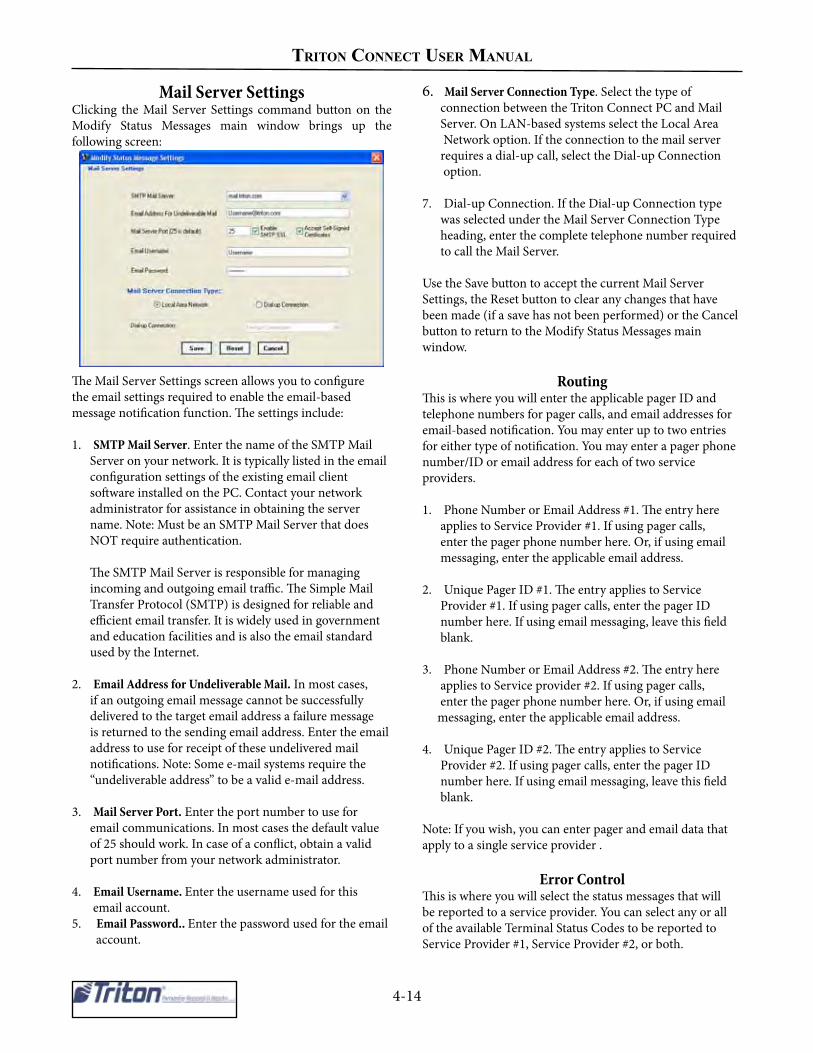
triton ConneCt uSer manual
4-14
Mail Server SettingsClicking the Mail Server Settings command button on theModify Status Messages main window brings up thefollowing screen:
The Mail Server Settings screen allows you to configurethe email settings required to enable the email-basedmessage notification function. The settings include:
1. SMTP Mail Server. Enter the name of the SMTP Mail Server on your network. It is typically listed in the email configuration settings of the existing email client software installed on the PC. Contact your network administrator for assistance in obtaining the server name. Note: Must be an SMTP Mail Server that does NOT require authentication.
The SMTP Mail Server is responsible for managing incoming and outgoing email traffic. The Simple Mail Transfer Protocol (SMTP) is designed for reliable and efficient email transfer. It is widely used in government and education facilities and is also the email standard used by the Internet.
2. Email Address for Undeliverable Mail. In most cases, if an outgoing email message cannot be successfully delivered to the target email address a failure message is returned to the sending email address. Enter the email address to use for receipt of these undelivered mail notifications. Note: Some e-mail systems require the “undeliverable address” to be a valid e-mail address.
3. Mail Server Port. Enter the port number to use for email communications. In most cases the default value of 25 should work. In case of a conflict, obtain a valid port number from your network administrator.
4. Email Username. Enter the username used for this email account.5. Email Password.. Enter the password used for the email account.
6. Mail Server Connection Type. Select the type of connection between the Triton Connect PC and Mail Server. On LAN-based systems select the Local Area Network option. If the connection to the mail server requires a dial-up call, select the Dial-up Connection option.
7. Dial-up Connection. If the Dial-up Connection type was selected under the Mail Server Connection Type heading, enter the complete telephone number required to call the Mail Server.
Use the Save button to accept the current Mail ServerSettings, the Reset button to clear any changes that havebeen made (if a save has not been performed) or the Cancelbutton to return to the Modify Status Messages mainwindow.
RoutingThis is where you will enter the applicable pager ID andtelephone numbers for pager calls, and email addresses foremail-based notification. You may enter up to two entriesfor either type of notification. You may enter a pager phonenumber/ID or email address for each of two serviceproviders.
1. Phone Number or Email Address #1. The entry here applies to Service Provider #1. If using pager calls, enter the pager phone number here. Or, if using email messaging, enter the applicable email address.
2. Unique Pager ID #1. The entry applies to Service Provider #1. If using pager calls, enter the pager ID number here. If using email messaging, leave this field blank.
3. Phone Number or Email Address #2. The entry here applies to Service provider #2. If using pager calls, enter the pager phone number here. Or, if using email messaging, enter the applicable email address.
4. Unique Pager ID #2. The entry applies to Service Provider #2. If using pager calls, enter the pager ID number here. If using email messaging, leave this field blank.
Note: If you wish, you can enter pager and email data thatapply to a single service provider .
Error ControlThis is where you will select the status messages that willbe reported to a service provider. You can select any or allof the available Terminal Status Codes to be reported to Service Provider #1, Service Provider #2, or both.

4-15
CHAPTER 4- TERMINAL SETUP
1. Apply To. This is a drop-down list that allows you to select the service provider that will receive notification of the status messages visible in the Active list. 2. Active. This is the list of terminal status codes that will be reported to the service provider selected in Apply To.
3. Inactive. This is the list of terminal status codes that have not been chosen for monitoring. Any status codes listed here will not be reported to a service provider, or recorded in the Status History log. To move a status code from the Inactive list to the Active list, click on it with the mouse to highlight it, then click theAdd button. To move all status codes in the Inactive list tothe Active list, click the Add All button.
To remove a status code from the Active list, click on itwith the mouse to highlight it, then click the Clear button.To remove all status codes from the Active list, returningthem to the Inactive list, click the Clear All button.
Status
The buttons here enable you to Save the current settings,Reset or clear any changes that have been made (if a savehas not been performed) or Cancel (exit) the Modify StatusMessage Settings screen.
Schedule Database BackupPurpose
The purpose of this function is to create a terminal databasebackup file and to establish a database backup schedule
** IMPORTANT **All other Triton Connect applications MUST beclosed for the backup to occur.
Accessing the Schedule Database BackupFunction
Perform the following steps to access the Schedule DatabaseBackup function:
1. Start the Terminal Manager application.
2. From the Setup menu, select the Options item. When the sub-menu appears select the Schedule Database Backup option. The following dialog appears:
3. Click the Select a Backup Filename command button. A file navigation dialog box appears:
Note that a default filename is automatically entered.You may change the file name if you wish. You maysave the file to the default location (the Triton Connectinstallation directory) or navigate to a location of yourchoice. Click the Save button to save the file.
4. Determine the the number of days between backups and enter this number in the Number of Days Between Backups field.
5. Check the Backup Database at Scheduled Time checkbox to enable backups (to disable backups, leave the box unchecked).
6. After configuring the database backup settings, click the Done command button to save the information and schedule the next backup (Date of Next Backup). Otherwise, click the Cancel command button to cancel any changes.
Once the Date of Next Backup arrives, whenever theTerminal Manager is exited, the user will be presented witha prompt related to database backup. If the user responds tothe prompt with a Yes, the database will be backed up andthe date of the next backup will be scheduled.

triton ConneCt uSer manual
4-16
If the response is No, the Terminal Manager will exit, butwill continue to prompt the user upon subsequent exits withthe same message until the prompt is answered with a Yesor the Schedule Database Backup function is disabled.
Once a database has been backed up, the Date of LastBackup will be updated to show the date the backupoccurred. This date may be later than the originallyscheduled date if the user chooses to respond with a No tothe backup prompt for a number of days. The actual Dateof Last Backup will depend upon when the user allows thebackup to occur. The next backup date will be calculatedbased on the Number of Days Between Backups.
Repair/Compact/Replace Database
PurposeThe purpose of this function is to repair/compact theterminal database or replace the terminal database with apreviously created backup file.
Accessing the Repair/Compact/ReplaceDatabase Function
Follow these steps to access the Repair/Compact/ReplaceDatabase functions:
1. Start the Terminal Manager application.
2. From the File menu, select the Repair/Compact/ Replace Database option.
3. The Repair/Compact or Replace Database screen appears:
Click the command button associated with the databasemanagement function you want to use. The next two sections cover the two functions available from this screen: Repair/Compact Database and Replace Original Database WithBackup.
Repair/Compact DatabaseThis function enables you to correct errors that may occurin the Triton Connect main database. After the repairoperation is completed, the database is compacted (ifpossible). This can often speed up access to the database.
** IMPORTANT **All other Triton Connect applications MUST beclosed for the repair/compact to occur.
Follow these steps to use the Repair/Compact Databasefunction:
1. Click the Repair/Compact Database command button.2. The database compacting operation will start. No further input is required. At the conclusion of the operation you will be returned to the Terminal Manager main screen.
Replace Database With Backup
If your database is not working properly and the Repair/Compact Database function does not fix the problem, youcan replace the existing database with a backup.
Note: You will lose any database information received sincethe last backup was performed!
Follow these steps to replace the existing main databasewith a backup copy:
1. Click the Replace Original Database With Backup command button.
2. A warning message will appear. Proceed only if there is a problem with the existing database which requires reverting to an earlier version of the database. To proceed, click the OK button.
3. A file navigation dialog box appears. Use it to locate the backup file you want to use. Highlight the file and click the Open button. The database replace process will begin. Message boxes will report the progress and successful conclusion of the process.
4. Click OK to return to the Terminal Manager main screen.

4-17
CHAPTER 4- TERMINAL SETUP
Serial File Transfer over TCP/IPTriton Connect has the ability to send files to the ATM using serial file transfer mode over TCP/IP. Notethat this functionality is only of concern if using a serial communications device, such as RadioPAD, on theterminal.
‘Add New Terminal’ dialogSerial File Transfer can be enabled for a terminal when it is added to Triton Connect. In order to set TritonConnect to use Serial File Transfer mode for a terminal when initially adding it to Triton Connect, perform thefollowing steps:
1. Open the Terminal Manager.2. Open the Setup menu.3. Select “Add New Terminal”.4. With “ATM Connection Type” set to TCP/IP, click the “Use Serial File Transfer Protocol” checkbox. 5. Continue configuring the ATM in Triton Connect as normal.
6.0
Terminal Manager showing “ADD New Terminal” menu item.

triton ConneCt uSer manual
4-18
Add New Terminal window showing Use Serial File TransferProtocol checked and Connection Type set to TCP/IP
‘Modify Terminal’ dialogIf the ATM is already in the Triton Connect database, it can be set to use Serial File Transfer mode from theModify Terminal screen. To modify a terminal to use Serial File Transfer, perform the following steps: 1. Open the Terminal Manager. 2. Open the Setup menu. 3. Select “Modify Terminal” 4. Select the desired ATM from the list in the top left corner. 5. Click the “Use Serial File Transfer Protocol” checkbox. 6. Click the “Update” button.
6.0
Terminal Manager showing “Modify Terminal” menu item

CHAPTER 5 - GETTING TERMINAL DATA

TRIToN CoNNECT UsER MANUAL
5-2
IntroductionOnce you’ve installed Triton Connect, configured the CallMonitor application and added terminals to the database,you can begin scheduling calls to those terminals. Initially,you will probably want to get data from your terminals,especially to obtain a reference or baseline for any changesyou may want to make later.
Get Terminal Data FunctionThe Get Terminal Data function provides a number ofoptions that allow you to specify the kinds of data you wantto retrieve from your terminals. These options fall into thefollowing categories:
• Get Terminal Data• Get All Journal Data• Get Last-X Journal Data• Synchronize Date and Time• Get Error Status• Get Coupon Data• Get Selected Parameters
In this chapter you will learn how to use the Get TerminalData function to select the terminals you want to contactand specify the data retrieval options you want to use.
Accessing the Get Terminal Data Function
1. Start the Terminal Manager application.
2. From the Terminal Data menu, select the Get TerminalData option. The Get Terminal Data screen appears
Selecting a TerminalMany of the fields on the Get Terminal Data screen shouldbe familiar to you from the chapter on terminal setup. Inthat chapter you were introduced to these fields, and sawthat each helps to identify a particular terminal, and providescriteria that can be valuable when using the search orfiltering capabilities of Triton Connect to locate, identifyand group terminals.
Use the data to help identify and select the terminal(s) youwant to work with. The Terminal ID selection list isparticularly important: it provides a quick way to pick theterminal you want from a list of available terminals. If thelist is very long, it may be more efficient to use the Searchfeature to select a terminal. The Filters function is also veryuseful when you need to group terminals in smaller groups,according to some criteria previously specified.
If you know the ID of the terminal, the easiest method is toselect it directly from the Terminal ID drop-down list:
This works great if you’re dealing with a single terminal. Ifyou want to broadcast your data retrieval request to multipleterminals, you can use the Broadcast feature.
Click the Broadcast button:
The Build Broadcast List appears:

CHAPTER 5- GETTING TERMINAL DATA
5-3
Highlight the terminals yout to select in the Availablelist:
If you want to remove a selected terminal from the BroadcastList, select it:
Then click the Remove -> button to return the selectedterminal to the Available List.
Notice that when you select a terminal, in either theBroadcast or Available Lists, a portion of the address datafor that terminal appears in the fields at the lower part ofthe screen:
Click the Done button to return to the Get Terminal Datamain screen.
The Terminal ID list will change to show only the terminalsselected by the Broadcast feature:
Click the <-Add button to add the highlighted terminal tothe Broadcast list:
Repeat the last two steps for each terminal you want toinclude in the broadcast. If you want to broadcast to allterminals in the Available List, you can use the<-Select All button to move all terminals to the Broadcastlist in a single step:
Use the Clear All -> button to move all terminals in theBroadcast list back to the Available List.
TECHNIQUES FOR SELECTINGMULTIPLE TERMINALS
To highlight a group of terminals, click once on thefirst terminal, then hold down the SHIFT key whileclicking on the last terminal in the group. This willhighlight the first terminal, the last terminal and anyterminals in between.
To highlight multiple terminals that do not fall neatlyinto a group, hold down the CTRL key while youclick on any terminal anywhere in the list.

TRIToN CoNNECT UsER MANUAL
5-4
Selecting a Data OptionOnce you’ve selected the terminal(s) you want to work with,use Select Options to choose an action to perform. Thereare seven options available, as shown here:
You can use the check boxes to choose one or severaloptions to take place when you initiate the data retrievalaction.NOTE: Some options may not be available on the screen.This means the terminal model does not support thatfunction.
Get Terminal Parameters
Triton Connect will obtain all terminal parameter data forthe selected terminal(s).
Get All Journal Data
This function will obtain all journal data for the selectedterminal(s). Once selected, initiate the data retrieval byclicking the Get Data button:
The following window appears:
Enter the Date/Time interval for optaining journal data.
JOURNAL CLEARING
CAUTION: If Journal Clearing is set to Manual, andthe Electronic Journal in the terminal has not beencleared before the next Get Journal Data command isissued, the old journal entries will still be present in thejournal. These entries will be received during thedownload and stored in the journal database,duplicating the entries already stored there!
IMPORTANT: The Electronic Journal cannot hold anunlimited number of entries. The 8-bit machines (9100/96XX/97XX/Mako/SS) can hold at most 2045 journalentries. The 32-bit machines (FT/RL/RT/9800) hold32,768 entries. Based on size of available RAM in unit,graphics can also reduce the number of available journalstorage.
If the journal size limit is reached the terminal will enteran OUT OF SERVICE condition and will remain in thatstate until the journal is cleared!
Get Last-X Journal Data
If you only want to obtain a subset of the set of records,you can select this function. The records are retrievedbeginning with the most current record and workingbackward from that point. For example, entering 1000 inthe data entry box will cause the retrieve function to obtainthe most recent 1000 journal records from the terminal. Ifthe number of entries you enter is greater than the totalnumber of entries actually stored in the journal, all recordswill be retrieved.
Synchronize Date & Time
The selected terminal(s) date and time are set to the samedate and time as the Triton Connect PC (accounting for time zone and daylight savings differences, if any).

CHAPTER 5- GETTING TERMINAL DATA
5-5
Get Error Status
Triton Connect will obtain all terminal error statusinformation for the selected terminal(s). When you chooseGet Terminal Parameters, the Select Options functionautomatically checks the Get Error Status option. If youdon’t want to obtain error status, you can simply “uncheck”it.
*NOTE *Get Error Status is automatically selected as part ofGet Terminal Parameters. To get ONLY the errorstatus, uncheck Get Terminal Paramaters.
Get Coupon Data
When you click the checkbox for this option a messagebox will appear:
The message asks if you want to Clear Coupon Data?Answer Yes if you want the terminal to clear out any storedcoupon totals after the coupon data is retrieved. AnswerNo if you want to retain any previous totals after the coupondata is retrieved.
NUMBER OF COUPON DISPENSESThe terminal can track up to 99,999 coupondispenses. The current total is retrieved by the GetCoupon function, and is available for analysis usingthe Coupon Report function of the Reports Manager
Get Selected Parameters Get Sellected Parameters
This option allows the user to retrieve selected parametersinstead of the entire parameter list.
* NOTE *In order to select this option, the “Get TerminalParameters” option must be unchecked
Select the parameters you want to retrieve by highlightingthe available options. You can select more than one optionby holding the Control key (CTRL) down when you select.
Once you’ve selected the parameters you want to retrieve,click the “Add” button to enter in the “Parameters toReceive” and click “OK”.

TRIToN CoNNECT UsER MANUAL
5-6
Call SchedulingOnce you’ve selected the terminal(s) you want to work with,and specified the data options you want, it’s time to initiatethe data retrieval action. You will do this by clicking theGet Data button:
When you do so, a scheduling window appears:
The scheduling window provides a means for you to choosea date, time, and contact interval to use when calling theterminal(s) you selected earlier.
Notice that the scheduler appears with the current data andtime already loaded and ready to use. It is provided as aquick way to schedule an immediate, one-time only call tothe selected terminal(s). If you want to use it, simply clickOK, and the call will be scheduled to take place immediately.
If the default contact time is not acceptable, you can changeit to whatever you wish. The scheduler window offers allthe information you need to create a customized contacttime, including a breakdown of the scheduling format andan example entry.
As an additional aid in understanding and composing calltimes, a table has been included on the next page, whichprovides an additional example, as well as a breakdown ofeach part of the contact time. The table also provides spaceto allow you to write in the values for contact times youcompose yourself, if you desire.
Once a suitable contact time has been composed, simplyclick OK to accept it. You can view the status of the call invarious ways, which will be covered in the next chapter,Status Monitoring.
PERSISTENT CALLSWhen you select an Interval Count and Interval, youare specifying that you want the terminal to be calledautomatically, on a repeating basis. An Interval Countand Interval of 2,d, for example, tells Triton Connectto make calls every two days, until you change thecontact schedule.
As additional examples, 3,h would specify callsevery three hours, 2,w would be every two weeks,6,m would be every 6 months, and 1,y would be oncea year.
Calls that repeat on a continuing basis are generallyreferred to as persistent calls.
* NOTE *When entering Persistent Calls values, ensure thereare no spaces between the AM/PM, commas, andvalues.

CHAPTER 5- GETTING TERMINAL DATA
5-7
TABLE 5-1 CALL SCHEDULINGEXAMPLE:
Call the terminal on December 5, 1996, at eight thirty in the morning, then two days later, at the same time. continue making calls every two days.
12/5/96 8:30 AM,2,d___ __ _____ ___ __ __ ___
Month Day Year Hour:Minute AM/PM InverterCount
Interval
:::::
VALUESMonth Use 1-12, corresponding to the months January through December.Day Use 1-31, as appropriate for the month in question.Year Valid for years 1980 through 2080AM/PM Hours in standard 12-hour time format. Minutes can be 0-59.IntervalCount
Select an Interval Count appropriate to the Interval type chosen. TheInterval Count represents the number of Intervals between calls, beginningat the start day and time you specified. For one-time-only calls, do notinclude an Interval Count.
Interval Valid intervals are: H=Hours, D=Days, W=Week, M=Month. For one-time-only calls, do not include an Interval.

TRIToN CoNNECT UsER MANUAL
5-8
THIS PAGE INTENTIONALLY LEFT BLANK

CHAPTER 6- STATUS MONITORING
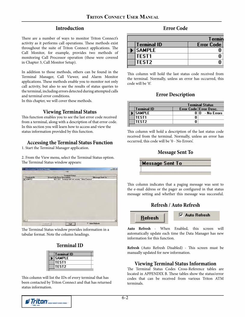
TRITON CONNECT USER MANUAl
6-2
Introduction
There are a number of ways to monitor Triton Connect’sactivity as it performs call operations. These methods existthroughout the suite of Triton Connect applications. TheCall Monitor, for example, provides two methods ofmonitoring Call Processor operation (these were coveredin Chapter 3, Call Monitor Setup).
In addition to those methods, others can be found in theTerminal Manager, Call Viewer, and Alarm Monitorapplications. These methods enable you to monitor not onlycall activity, but also to see the results of status queries tothe terminal, including errors detected during attempted callsand terminal error conditions.In this chapter, we will cover these methods.
Viewing Terminal StatusThis function enables you to see the last error code receivedfrom a terminal, along with a description of that error code.In this section you will learn how to access and view thestatus information provided by this function.
Accessing the Terminal Status Function1. Start the Terminal Manager application.
2. From the View menu, select the Terminal Status option.The Terminal Status window appears:
The Terminal Status window provides information in atabular format. Note the column headings.
Terminal ID
This column will list the IDs of every terminal that hasbeen contacted by Triton Connect and that has returnedstatus information.
Error Code
This column will hold the last status code received fromthe terminal. Normally, unless an error has occurred, thiscode will be ‘0’.
Error Description
This column will hold a description of the last status codereceived from the terminal. Normally, unless an error hasoccurred, this code will be ‘0 - No Errors’.
Message Sent To
This column indicates that a paging message was sent tothe e-mail ddress or the pager as configured in that statusmessage setting and whether this message was successful.
Refresh / Auto Refresh
Auto Refresh - When Enabled, this screen willautomatically update each time the Data Manager has newinformation for this function.
Refresh (Auto Refresh Disabled) - This screen must bemanually updated for new information.
Viewing Terminal Status InformationThe Terminal Status Codes Cross-Reference tables arelocated in APPENDIX B. These tables show the status/errorcodes that can be received from various Triton ATMterminals.

CHAPTER 3 - CAll MONITOR
6-3
Viewing the Call List
Once you’ve scheduled a terminal for contact, the call isplaced in the Call List, which holds a record of the request,waiting until the scheduled call time occurs. At that time,Triton Connect attempts to place the call to the terminal,using an available Call Processor to handle thecommunication details involved.
CALL DELAY
There is a fifteen (15) second delay betweenconsecutive outgoing calls. This cannot be changed.This delay provides a “window of opportunity” forincoming calls from terminals to be received.
NOTE: If Triton Connect is waiting on an incomingcall from an ATM that has not or will not call back,then it can wait up to an hour before picking up thenext call in the call list.
If while monitoring the call list you observe anunusually long delay in receiving a return call froma terminal, you may wish to delete the call from thelist, to allow other calls to be processed on theaffected telephone line.
In such cases troubleshooting of the affected terminalmay be required to correct the problem
* NOTE *The Call List can be sorted ascending anddescending by clicking on the field headings
The Call List provides quite a lot of information concerningeach call. Its tabular layout makes it easy to check the callstatus of a particular terminal. In this section, you will learnhow to access and interpret the information provided bythe Call List.
Accessing the Call List Function
1. Start the Terminal Manager application.
2. From the View menu, select the Terminal Call List option. The Call List window appears:
Viewing Call List Information
The Call List uses a table approach to present information.It provides a single-line entry for each terminal ID that isscheduled for contact. On each line, column headingsidentify the types of information available in the entry. Tosee all of the column headings you will need to scroll thedisplay horizontally, as in the following examples:
These headings are briefly discussed in the followingparagraphs.
Terminal ID. The name Triton Connect uses to identifythis terminal in the database.
Time to Call. This is the time of the next scheduled call tothis terminal.
Attempt. This is the number of attempts Triton Connecthas made to contact this terminal. Triton Connect will makeup to five attempts to reach the terminal before reporting acall error.
Time Contacted. This is the time a successful call to theterminal was achieved.
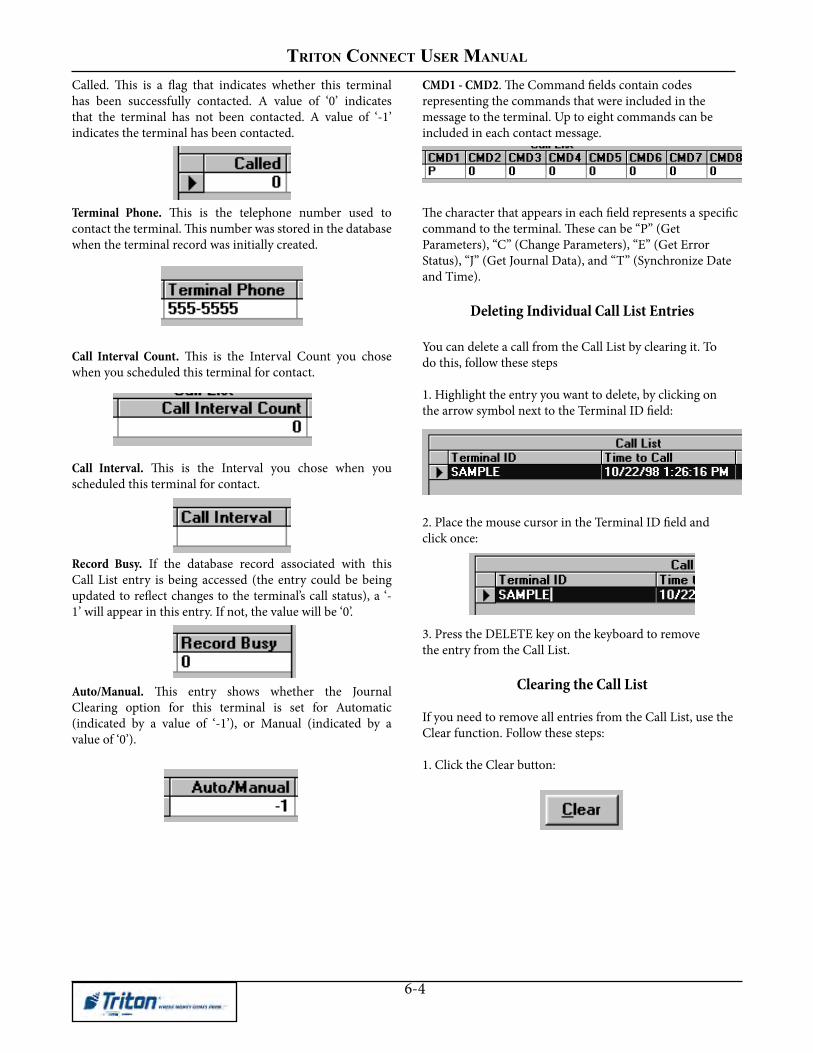
TRITON CONNECT USER MANUAl
6-4
Called. This is a flag that indicates whether this terminalhas been successfully contacted. A value of ‘0’ indicatesthat the terminal has not been contacted. A value of ‘-1’indicates the terminal has been contacted.
Terminal Phone. This is the telephone number used tocontact the terminal. This number was stored in the databasewhen the terminal record was initially created.
Call Interval Count. This is the Interval Count you chosewhen you scheduled this terminal for contact.
Call Interval. This is the Interval you chose when youscheduled this terminal for contact.
Record Busy. If the database record associated with thisCall List entry is being accessed (the entry could be beingupdated to reflect changes to the terminal’s call status), a ‘-1’ will appear in this entry. If not, the value will be ‘0’.
Auto/Manual. This entry shows whether the JournalClearing option for this terminal is set for Automatic(indicated by a value of ‘-1’), or Manual (indicated by avalue of ‘0’).
CMD1 - CMD2. The Command fields contain codesrepresenting the commands that were included in themessage to the terminal. Up to eight commands can beincluded in each contact message.
The character that appears in each field represents a specificcommand to the terminal. These can be “P” (GetParameters), “C” (Change Parameters), “E” (Get ErrorStatus), “J” (Get Journal Data), and “T” (Synchronize Dateand Time).
Deleting Individual Call List Entries
You can delete a call from the Call List by clearing it. Todo this, follow these steps
1. Highlight the entry you want to delete, by clicking onthe arrow symbol next to the Terminal ID field:
2. Place the mouse cursor in the Terminal ID field andclick once:
3. Press the DELETE key on the keyboard to removethe entry from the Call List.
Clearing the Call List
If you need to remove all entries from the Call List, use theClear function. Follow these steps:
1. Click the Clear button:

CHAPTER 3 - CAll MONITOR
6-5
A confirmation message appears:
2. Click the Yes button to clear all items from the CallList.
Viewing the Call Error List
The Terminal Error List stores entries for failed terminalcontacts. These failed contacts fall into the following twocategories:
• Five attempts were made to contact a terminal,but the terminal did not answer.
• A terminal was called successfully, but did notreturn the call.
Accessing the Call Error List Function1. Start the Terminal Manager application.
2. From the View menu, select the Terminal Call ErrorList option. The Call Error List window appears:
Viewing Call Error List Information
The error list information is presented in a grid arrangement.Each line entry represents a single terminal contact. Thecolumns are the various data fields that contain the dataassociated with that terminal contact attempt. To see all ofthe column headings you will need to scroll the displayhorizontally.
These headings are briefly discussed below:
Terminal ID. The name Triton Connect uses to identifythis terminal in the database.
Time to Call. This is the time of the next scheduled call tothis terminal.
Attempt. This is the number of attempts Triton Connecthas made to contact this terminal. Triton Connect will makeup to five attempts to reach the terminal before reporting acall error.
Time Contacted. This is the time a successful call to theterminal was achieved.
Called. This is a flag that indicates whether this terminalhas been successfully contacted. A value of ‘0’ indicatesthat the terminal has not been contacted. A value of ‘-1’indicates the terminal has been contacted.
Terminal Phone. This is the telephone number used tocontact the terminal. This number was stored in the databasewhen the terminal record was initially created.

TRITON CONNECT USER MANUAl
6-6
Call Interval Count. This is the Interval Count you chosewhen you scheduled this terminal for contact.
Call Interval. This is the Interval you chose when youscheduled this terminal for contact.
Auto/Manual. This entry shows whether the JournalClearing option for this terminal is set for Automatic(indicated by a value of ‘-1’), or Manual (indicated by avalue of ‘0’).
CMD1 - CMD2. The Command fields contain codesrepresenting the commands that were included in themessage to the terminal. Up to eight commands can beincluded in each contact message.
The character that appears in each field represents a specificcommand to the terminal. These can be “P” (GetParameters), “C” (Change Parameters), “E” (Get ErrorStatus), “J” (Get Journal Data), and “T” (Synchronize Dateand Time).
Rescheduling Calls
If you wish, you can place a failed call back in the CallList, using the rescheduling function. To do so, follow thesesteps:
1. Click the Reschedule button:
The following confirmation message appears:
2. Answer Yes to the message. A call scheduling dialogbox appears:
Schedule a time for the next attempt and click OK. Theentry will be removed from the Call Error List and placedback in the Call List.
Clearing the Call Error List
The Terminal Error List may contain only entries that willnot need to be rescheduled, or serve no other useful purpose.To remove these entries from the list, follow these steps:
1. Click the Clear command button:
2. A series of confirmation messages will appear:

CHAPTER 3 - CAll MONITOR
6-7
Respond Yes to these message to clear ALL entries fromthe Terminal Error List.
Refreshing the Error List
When the Call Error List is first displayed, it shows a“snapshot” of the current status of terminal contact errors.This “frozen” picture of events may not reflect the mostrecent entries, especially if the list has been displayed forsome time.
To refresh the display, click the Refresh button:
The display will be updated with the most current ErrorList status.
Using the Call Viewer
Call Processors handle the details of placing calls toterminals and answering calls from terminals. Theycommunicate directly with your communications hardwareto manage the transfer of data between your Triton ConnectPC or network and one or more remote terminals.
Because the Call Processors will usually be running on theModem Server PC in a network environment, other PCs onthe network may not have convenient access to the CallProcessors. Triton Connect provides a solution: the CallViewer application allows any legally licensed PC on thenetwork to remotely view the activity of each CallProcessor.
In this section of the chapter, you’ll learn how to accessand use the Call Viewer.
Accessing the Call Viewer1a. Start the Terminal Manager application. From the Viewmenu, select the Call Processors option.
- OR -
1b. Select the Call Viewer option from the Triton Connectapplications group, which can be reached via theWindows Start/Programs menu.
The Call Viewer dialog box appears:
Connecting to the Call Monitor
When the Call Viewer window appears the utility willattempt to contact the Call Monitor, using a TCP/IPconnection.
** IMPORTANT **The TCP/IP protocol must be installed on thecomputer to enable Call Viewer-to-Call Monitorcommunications! See Chapter 2, Installation, forinstructions on installing the TCP/IP protocol.
The Call Processors that are currently running will be listed:
If there are no Call Processors listed check the following:
• Are any Call Processors running? Check the Call Monitor and start the Call Processor(s), if necessary.
• Is the Call Viewer enabled at the Call Monitor? Make sure the Enable Call Viewer option in the Call Monitor’s Diagnostic menu is checked.
• Are the TCP/IP address and/or Port Number settings correct? Click the TCP/IP Settings option in the Call Monitor’s Settings menu. This will open the TCP/IP Settings dialog. Make a note of the TCP/IP Address and TCP/IP Port number for the Call Monitorto- Call Viewer entry.
Click the TCP/IP Settings option in the Call Viewer’sSettings menu. This will open the Settings dialog.Check the IP Address and Call Monitor Port Numbersettings. The settings should match those noted for theCall Monitor. If necesary, change the values to matchthe Call Monitor settings.

TRITON CONNECT USER MANUAl
6-8
Managing Viewer Windows
To see the activity of an individual Call Processor, select itin the list and click the Show button:
A viewer window will open, showing the activity of thatCall Processor, as in this example:
Note that the Show button changes to a Hide button if theviewer window for the currently selected Call Processor isvisible
:
You can click the Hide button to make the currently selectedviewer window invisible (the button will change to Show,allowing you to display the viewer again, as needed).
To quickly display the viewer windows for ALL runningCall Processors click the Show All button:
Or use the Hide All button to temporarily make ALLdisplayed viewers invisible.
Use the Make All Same Size button to force all open viewerdialogs to match the size of the currently selected call viewerdialog.
You can pause and resume the activity of all displayedviewer windows by clicking the Screens Paused option inthe Settings menu:
A checkmark indicates that all viewer windows are paused.You can check the title bar of a viewer window to see if thestatus is “Screen Paused.”
You can also pause the activity of a selected viewer byclicking the Pause button on that viewer’s dialog.

CHAPTER 3 - CAll MONITOR
6-9
Displaying Status Boxes
If you want to view a summary of each Call Processor’sactivity, click the Display Status Boxes command button:
The Call Viewer dialog changes to display a single-lineactivity summary for each active Call Processor:
You can use this display if you want to see a summary ofeach call Processor’s activity, but don’t want to fill thescreen with individual viewer windows. This display iscomparable to the single-line summary display availableat the Call Monitor main dialog. To hide this display, clickthe Remove Status Boxes command button:
Alarm Monitor
The Alarm Monitor application provides a log of terminalerror conditions. When it is running, it automaticallyreceives error status as needed as calls from terminals arereceived. In this section you will learn how to access andview the status information provided by the Alarm Monitor.
Accessing the Alarm Monitor Function
Start the Triton Connect Alarm Monitor application byselecting its option from the Windows Start/Programs/TritonConnect menu. The Alarm Monitor application windowappears:
Viewing Alarm Monitor Information
The Alarm Monitor status window provides information ina tabular format. It provides a single-line entry for eachterminal ID that reported an error condition. On each line,column headings identify the types of information availablein the entry. To see all of the column headings you willneed to scroll the display horizontally.
Most of the information presented for each terminal ID isextracted from the database, and serves to provide additionalidentifying information for each terminal, such as terminaladdress, points of contact, etc. This information was initiallyentered into the database when the terminal was added (seeChapter 4, terminal Setup, for procedures).
Of particular concern to you will, of course, be the ErrorCondition column. It is here that the most recent errorindication for the terminal will be provided. A completelisting of the error descriptions is provided in Terminal StatusCodes Cross-Reference Tables on pages 6-3 through 6-16.Refer to your ATM manual for further information on errorcodes.
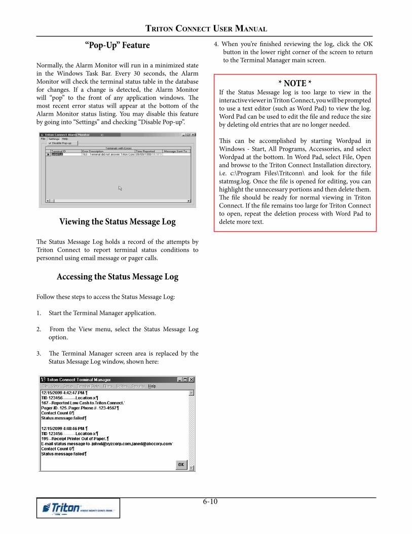
TRITON CONNECT USER MANUAl
6-10
“Pop-Up” Feature
Normally, the Alarm Monitor will run in a minimized statein the Windows Task Bar. Every 30 seconds, the AlarmMonitor will check the terminal status table in the databasefor changes. If a change is detected, the Alarm Monitorwill “pop” to the front of any application windows. Themost recent error status will appear at the bottom of theAlarm Monitor status listing. You may disable this featureby going into “Settings” and checking “Disable Pop-up”.
Viewing the Status Message Log
The Status Message Log holds a record of the attempts byTriton Connect to report terminal status conditions topersonnel using email message or pager calls.
Accessing the Status Message Log
Follow these steps to access the Status Message Log:
1. Start the Terminal Manager application.
2. From the View menu, select the Status Message Log option.
3. The Terminal Manager screen area is replaced by the Status Message Log window, shown here:
4. When you’re finished reviewing the log, click the OK button in the lower right corner of the screen to return to the Terminal Manager main screen.
* NOTE *If the Status Message log is too large to view in theinteractive viewer in Triton Connect, you will be promptedto use a text editor (such as Word Pad) to view the log.Word Pad can be used to edit the file and reduce the sizeby deleting old entries that are no longer needed.
This can be accomplished by starting Wordpad inWindows - Start, All Programs, Accessories, and selectWordpad at the bottom. In Word Pad, select File, Openand browse to the Triton Connect Installation directory,i.e. c:\Program Files\Tritconn\ and look for the fiilestatmsg.log. Once the file is opened for editing, you canhighlight the unnecessary portions and then delete them.The file should be ready for normal viewing in TritonConnect. If the file remains too large for Triton Connectto open, repeat the deletion process with Word Pad todelete more text.

CHAPTER 7- USING FILTERS

TRITON CONNECT USERS MANUAL
7-2
IntroductionThe filters function enables the creation of special filteringstatements that act as database filters, limiting the numberof records visible at any one time to only those records thatmatch a particular set of conditions that you specify in thestatement. This feature can be quite useful when workingwith a large number of terminal records, (or for operatorsin a network environment who handle only small groups ofthe entire terminal database), and only certain records areof immediate interest.
For example, only those terminal records for a particularcity can be visible, or only those terminals that belong to aparticular organization. There are many possibilities. Ingeneral, activating a filter allows only those terminal recordsthat match the filter criteria to be visible in the variousterminal management functions (this includes all TerminalData menu functions as well as the Delete and ModifyTerminal, View and Set Terminal Parameters, ViewTerminal, Journal Data, Terminal Setup and Report Managerfunctions).
When working in the terminal management functions, asmall icon can be seen in the lower right corner of thefunction window. This icon shows the status of the filterfunction. If a filter is currently active, the icon appears asshown here:
Placing the mouse cursor over the icon will cause a “balloonhelp” pop-up to display the name of the filter:
If no filters are currently active, the icon will be crossedout, as shown here:
The Filters MenuThe Filters menu contains the options shown here:
The Create/Edit/Delete option starts the Create/Edit/Deletefunction, which is used to create and manage filters. TheSet Active Filter option is a cascading menu; highlightingit with the mouse opens another menu that lists the availablefilters by name, as shown in this example:
To enable a filter in the list, simply click on it with themouse. When you do so, the selected filter becomes theactive filter, and also appears in a list at the bottom of theFilters drop-down menu box, as the Current Filter:
To turn off all filters, select the No Filter option from theSet Active Filter sub-menu:
Accessing the Filters FunctionTo view the Filters window perform the following steps:
1. Start the Terminal Manager application.
2. From the Filters menu, select the Create/Edit/DeleteFilters option. The Create/Edit/Delete Filters functionwindow appears:

CHAPTER 7- USING FILTERS
7-3
Filter Creation and Management
As stated earlier, the purpose of the Create/Edit/DeleteFilters function is the creation and management of filterstatements. These statements act as database filters, makingonly those terminal data records that match a particulardescriptive criteria available at any given time.
The functions that enable you to create and manage thesestatements are described under the following headings:
• Creating A Filter
• Viewing A Filter
• Saving A Filter
• Editing A Filter
• Deleting A Filter
Creating a FilterCreating a filter involves constructing a filter statement byjoining together a combination of drop-down list selectionsand user-defined entries. Together, these components makeup a statement that describes the filtering operation youwant.
The New Command
Click on this command button to clear the File Name textentry box and prepare the controls to accept the entriesthat make up a new filter statement.
Enter the name of the filter you are creating in the FilterName text entry box:
Building the Filter Statement
Three drop-down list boxes and a text entry box providethe tools needed to build the filter statement:
The first list contains the fields that are common to eachterminal data record. These are the fields that were filled inwith data when the record was initially created, andconsequently represent important searchable parameters.The filter statement is based on one or more fields from thislisting. Perform the following steps to create a new filterstatement:
1. Begin the construction of the filter statement byselecting the initial field of interest from the first dropdownlist box. By selecting a field from this list youbegin to limit the range of records that will pass throughthe “filter.” If necessary, additional fields from this listwill be selected as you build a filter statement that is asspecific as necessary:
2. Continue by choosing a comparison parameter fromthe second list. These values represent various waysthat the field selected in the first box can be comparedto the user-specified value that is entered in the thirdbox.

TRITON CONNECT USERS MANUAL
7-4
3. Enter a value for comparison in the third box. This is a“real” value that can be compared to the field specifiedin the first box. Select a value that helps to “zero” inon a smaller span of records within the range alreadylimited by the selection of the first field:
4. Finish the filter statement with the <END> command,or if necessary further refine the statement by linkingit to one or more additional statements using the And/Or commands. Selecting either And or Or begins a newstatement line, which you build using the previoussteps. Up to five additional lines may be added to thefirst statement. When satisfied with the final line, usethe <END> command to complete the statement.
Viewing a FilterThe Generated SQL Statement window lets you see theactual commands that are joined together as you build thefilter statement. This is how the final statement looks, usingthe entries from our example:
MORE EXAMPLES
Here are some additional examples of filtercommands:
By combining the available filter criteria commandswith words or phrases that describe specific terminalsor groups of terminals in your database you cancreate filter statements to meet a wide range of needs
Basically, this statement can be interpreted to read, “Selectall records from the CONFIGURE table where the entry inthe TID (Terminal ID) field of the table contains ‘SAMPLE.’When this filter is active, only those terminal data recordswhere the Terminal ID includes the word SAMPLE will beavailable.
Saving a Filter
Click on the Save command button to save the filterstatement with the name you specified earlier. All fieldswill clear, allowing for the creation of another filter and thenewly saved filter will appear in the drop-down portion ofthe box:
On a standalone (non-networked) system the procedure touse a filter after it has been saved is straightforward: simplyclick on the filter entry in the Set Active Filter menu toactivate it (see the discussion concerning the Filters menuearlier in this section). In a networked environment,however, some additional considerations are involved.
To see and access filters created at other workstations onthe network, you must first update the Filters database byselecting any available filter, or by existing and re-enteringthe Terminal Manager Application. This operation willupdate or refresh the list in the Set Active Filters menu,displaying any additional entries for filters that have beencreated by other operators.
Modifying a Filter
An existing filter can be easily modified. The followingsteps summarize the procedure to follow:
1. Select an Existing Filter.
2. Click on the Load command button.
3. Change the Filter Name, if desired.

CHAPTER 7- USING FILTERS
7-5
4. Change the filter statement components as necessary.If the statement has multiple lines, select and edit theadditional lines as needed. If you wish to delete a line,select the <END> statement on the previous line.
5. Click the Save command button.
Deleting a Filter
When a filter is no longer needed, delete it by performingthe following steps:
1. Select a Filter from the Filter Name list box.
2. Click the Load command button to load the filterstatement.
3. Click the Delete command button.
Answer Yes to the confirmation message to remove thefilter:
Filter by paramentersTo create a filter utilizing paramenters, perform the follow-ing steps:
1. Open the Terminal Manager.
2 Open the Filters menu.
3. Click Create/Edit/Delete Filter.
4. Enter the name for the new filter in the Filter Name field.
5. In the Build Parameter Filter area, select the parameter in the first field. Select Matches or IsNot in the second field. Enter Value in the third field.
6. In the last field, select either End, And, or Or. For And or Or, an additional parameter will be selected toe either match and additional value as in step 5.
7. click the save button and then click yes.

TRITON CONNECT USERS MANUAL
7-6

Chapter 8 - terminal parameters

8-2
triton ConneCt User manUal
Introduction
In this chapter we will introduce you to terminal parameters. These are the values that affect terminal operation or report the status of various terminal operations. Many terminal parameters are configurable, allowing you to make changes in the operation of a selected terminal by altering the value or state of the applicable parameter. Other parameters are read-only, meaning that you can view the parameters, but not change their values.
Accessing Terminal Parameters
1. Start the Terminal Manager application.
2. If you want only to view parameters: at the Terminal Data menu, select the View Terminal Parameters option.
3. If you want to change parameters: at the Terminal Data menu, select the Set Terminal Parameters option.
The Terminal Parameters screen appears. By default, the Select Terminal screen is shown first:
Selecting TerminalsThe Select Terminal window provides a Select Terminal ID list, which is populated with the names of all terminals currently loaded in the terminal database, or a subset of those termi-nals, as determined by the currently active Filter value, if the Filter feature is enabled. (See Chapter 7, Using Filters, for more information.)
Next, you’ll need to select one or more terminals to view or configure. The next two sections describe how to do this.
Selecting a Terminal - General Procedure
1. Select the ID of the terminal you want to work with, using the Select Terminal ID drop-down list:
Alternatively, you can use the Next and Previous buttons to move forward or backward through the list of available terminals:
Notice that when you select a terminal, a portion of the address data for that terminal appears in the fields at the left of the main window:
**** WARNING ****The ability to make changes in terminal operation is a powerful feature provided by Triton Connect! You must exercise caution when making any changes; only make a change when you understand exactly the effect it will have on the terminal!
* NOTE *You must be logged in the Terminal Manager with Supervisor permissions in order to change or set parameters.

8-3
Chapter 8 -terminal parameters
** IMPORTANT **A terminal must have been previously contacted and parameters downloaded to be available for viewing! If you select a terminal for which no data has been previously downloaded, a warning message will appear on the Terminal Parameters main window:
Also, the View Parameters button will be disabled.
2. After selecting a terminal, click the View Parameters button:
The Select Terminal window is replaced with selection tabs for the various terminal parameter categories:
The following terminal parameter categories are available:
• AdGraphics/FileManager
• AdvancedSettings •Passwords • Amounts •ReceiptGraphics
• CassetteStat •Status
• Comm •Surcharge
• Control •TerminalTotals
• Format •TextAdScreens
• ISONo./OwnerInfo •LEDSign Message • TritonConnectSettings
• Messages/Coupons
• VersionNumbers
3. Select the tab for the parameter area you wish to view. The selected tab will present the state of the parameters as of the last time the parameters were retrieved from the currently terminal (See Chapter 5, Getting Terminal Data, for more information). The last contacted date and time is shown in the upper-right corner.
4. You can select a different terminal by clicking the Next or Previous buttons to more forward or backward through the list of available terminals.
When you click the Next or Previous button, the Select Terminal window will appear and the chosen terminal ID will be highlighted in the Select Terminal ID list. If you wish, you can choose a different terminal from the list. Once you’ve selected a terminal, click the View Parameters button to return to the parameter tabs view for that terminal.
Selecting Multiple Terminals (BroadcastFeature)
1. Click the Broadcast button:
The Build Broadcast List appears:

8-4
triton ConneCt User manUal
2. Highlight the terminals you want to select in the Available list:
3. Click the <-Add button to add the highlighted terminal(s) to the Broadcast list:
4. Repeat the last two steps for any other terminal(s) you want to add to the Broadcast List.
If you want to broadcast to all terminals in the Available List, use the <-Select All button to highlight all of the terminals and click the <-Add button to move them to the Broadcast list in a single step.
5. If you want to remove one or more terminals from the Broadcast List, use the procedures described in Step 2 to highlight the terminal(s) and then click the Remove -> button to return the terminal(s) to the Available List.
6. If you want to move all the terminals in the Broadcast list back to the Available List, click the Clear All -> button.
7. Select a terminal in the Broadcast List to enable the View Parameters button:
Click the View Parameters button. The Select Terminal window is replaced with tabs for the various categories of terminal parameters, as shown here:
8. Once the parameter tabs appear, the broadcast list is no longer visible. To see which terminals are in the broadcast list, use the list box in the upper left corner of the Terminal Parameters main dialog:
This list box appears when at least one terminal has been added to the broadcast list. To scroll through the list, use the up and down arrows.
TECHNIQUESFORSELECTINGMULTIPLETERMINALS
To highlight a group of terminals, click once on the first terminal, then hold down the SHIFT key while clicking on the last terminal in the group. This will highlight the first terminal, the last terminal and any terminals in between.
To highlight multiple terminals that do not fall neatly into a group, hold down the CTRL key while you click on any terminal anywhere in the list.

8-5
Chapter 8 -terminal parameters
* NOTE *When broadcasting parameters, all ATMs should be of similiar type. For instance, graphics for a Model 97XX ATM can not be sent to a Model RL5000 ATM unit..
Setting Terminal Parameters
Select the parameter areas you want to work with by clicking on the applicable tab(s). Make the necessary parameter changes. Note the following:
1. When you make a change to a parameter the entry will appear RED to indicate the value has been changed.
Ifadataentryfieldorcontrolisnotapplicabletothecurrently selected terminal, the fieldor controlwillbegrayedoutordisabled.NOTE:Ifallchoicesaregrayedout,besureyouhavechosen“Set”parametersratherthan“View”.
2. If a single terminal is selected, each parameter change you made will be applied to that terminal only.
3. If a broadcast list was used, each parameter change you made will be applied to all terminals in the list.
After all parameter changes have been made, click the Send Parameters button to schedule the terminal(s) for contact.
This will bring up a call scheduling window:
The scheduling window provides a means for you to choose a date, time, and contact interval to use when calling the terminal(s) you selected earlier.
Notice that the scheduler appears with a contact time already loaded and ready to use. By default, this contact time is the current time. It is provided as a quick way to schedule an immediate, one-time only call to the selected terminal(s).
If you want to use it, simply click OK, and the call will be scheduled to take place immediately.
If the default contact time is not acceptable, you can change it to whatever you wish. The scheduler window offers all the information you need to create a customized contact time, including a breakdown of the scheduling format and an example entry.
Schedule a contact time for the terminal and accept it. The changes you made will be sent to the selected terminal (or multiple terminals, if the Broadcast feature was chosen) at the scheduled time.
Once a suitable contact time has been composed and entered in the scheduling window, click OK to accept it.

8-6
triton ConneCt User manUal
About Messages and Coupons
Messages use the terminal display screen to convey information to the customer. Messages are used to greet the customer, make promotional offers, encourage repeat use, etc. NOTE: The Store and Marketing Messages also print on the customer’s receipt.
Coupons are typically used as a promotional incentive, awarding a product, service, or discount as an incentive for making withdrawals from the terminal. Such awards or incentives are typically referred to as “prizes.”
Coupons are triggered by the occurrence of either a withdrawal above a certain level (Level Coupon), or as a random percentage of all withdrawals (Random Percentage).
When triggered as either a level-based or random event, the coupon is printed by the terminal at the conclusion of the transaction.
A notification screen appears on the terminal display to inform the customer that a prize award coupon is printing.
This tab lets you change message text, configure coupon parameters and select the language used by the terminal to present customer screens.
Changing Messages
Follow these steps to change a message:
1. Click the option button for the message you want to change, as in this example:
2. Edit the existing message or type a new message in the text window:
Use the provided keystroke sequences when editing text:
Messages/Coupons

8-7
Chapter 8 -terminal parameters
Enabling Coupons
Follow these steps to enable/disable Printed and Dispensed coupons:
1. Printed Coupons. Select the Yes option from the Coupon Enabled control to enable printed coupons. Select No to disable printed coupons.
2. Dispensed Coupons. Place a check in the Coupon Dispensing enabled checkbox to enable dispensed coupons. Remove the check to disable dispensed coupons. Note: Coupons are dispensed from a cassette other than currency.
SettingLevelandRandomCoupon Thresholds
If you want each customer to receive a prize coupon upon making a withdrawal of 20 dollars or more, for example, then set a Coupon Level of 20 dollars. Set the Random Percentage field to zero.
If you want a percentage of all customers to receive a coupon, no matter what the level of their withdrawal, establish a Random Percentage, such as 50 percent and set the Coupon Level to a value GREATER than the Maximum Withdrawal Amount.
By using both a level and percentage award, using the previous example values (Coupon Level of 20 and Random Percentage of 50) you can award coupons to ALL customers making withdrawals of 20 dollars or more and 50 percent of customers making withdrawals less than 20 dollars.
Follow these steps to set the award thresholds for Level and Random Coupons:
1. Level-BasedAward. Click inside the Coupon Level text box and enter a coupon level amount.
2. Random-Based Award. Click inside the Random Percentage text box and enter a percentage value.
LanguageSelection
The language selection features allow you to select the default language to use when presenting messages to the customer and to enable the presentation of messages in a bilingual format.
Follow these steps to configure the language selection options:
1. DefaultLanguage. Click the Default Language list to view the options. Language1 corresponds to the default (usually English) language. Language 2 corresponds to a second language, as determined by the terminal software version.
2. Multi-Lingual. Select the Yes option from the Mult Lingual control to enable presentation of customer screens in a bilingual format. Select No to disable the bilingual presentation.
Coupon Cassette Selection
This set of controls is READ ONLY; its purpose is to allow you to view the current state of the coupon cassette configuration in the terminal whose data is being viewed.
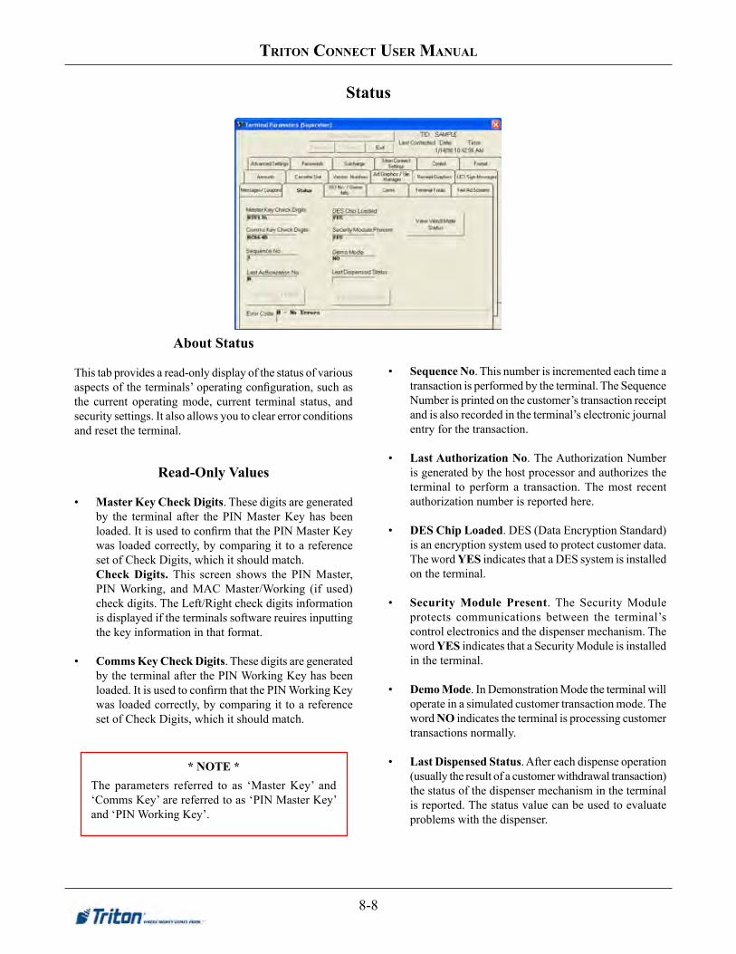
8-8
triton ConneCt User manUal
About Status
This tab provides a read-only display of the status of various aspects of the terminals’ operating configuration, such as the current operating mode, current terminal status, and security settings. It also allows you to clear error conditions and reset the terminal.
Read-Only Values
• Master Key Check Digits. These digits are generated by the terminal after the PIN Master Key has been loaded. It is used to confirm that the PIN Master Key was loaded correctly, by comparing it to a reference set of Check Digits, which it should match.
CheckDigits.This screen shows the PIN Master, PIN Working, and MAC Master/Working (if used) check digits. The Left/Right check digits information is displayed if the terminals software reuires inputting the key information in that format.
• Comms Key Check Digits. These digits are generated by the terminal after the PIN Working Key has been loaded. It is used to confirm that the PIN Working Key was loaded correctly, by comparing it to a reference set of Check Digits, which it should match.
• Sequence No. This number is incremented each time a transaction is performed by the terminal. The Sequence Number is printed on the customer’s transaction receipt and is also recorded in the terminal’s electronic journal entry for the transaction.
• LastAuthorizationNo. The Authorization Number is generated by the host processor and authorizes the terminal to perform a transaction. The most recent authorization number is reported here.
• DESChipLoaded. DES (Data Encryption Standard) is an encryption system used to protect customer data. The word YES indicates that a DES system is installed on the terminal.
• Security Module Present. The Security Module protects communications between the terminal’s control electronics and the dispenser mechanism. The word YES indicates that a Security Module is installed in the terminal.
• Demo Mode. In Demonstration Mode the terminal will operate in a simulated customer transaction mode. The word NO indicates the terminal is processing customer transactions normally.
• LastDispensedStatus. After each dispense operation (usually the result of a customer withdrawal transaction) the status of the dispenser mechanism in the terminal is reported. The status value can be used to evaluate problems with the dispenser.
Status
* NOTE *The parameters referred to as ‘Master Key’ and ‘Comms Key’ are referred to as ‘PIN Master Key’ and ‘PIN Working Key’.

8-9
Chapter 8 -terminal parameters
TERMINALSTATUSFEATURE
The ability to place the Terminal In Service or Out of Service must be supported by the ATM software running on the selected terminal(s). Otherwise, selecting this function will have no effect on terminal operation!
Terminal Service Status
This button shows the terminal service status that will take effect once parameters are sent to the terminal. By default, the service status is set to Terminal In Service. Clicking the button changes the status to Terminal Out of Service.
View VendMate Status
The View Vend Mate Status function has not been activated in this version of Triton Connect.
Clearing Errors and Resetting the ATM
The Error Code line displays the most recent terminal status condition:
If an error status is shown, follow these steps to clear the error status:
1. Click the Clear Error and Reset ATM button. The <Cleared> label is added to the error status and the entire entry is marked in RED. Red color indicates a changed parameter not yet sent to the terminal.
2. After making any other required parameter changes, click the Send Parameters button to schedule the terminal for contact.
When parameters are sent to the terminal the error status will be reset. If the condition that caused the error status is corrected the updated status will be displayed. If the error was not cleared contact your service organization. If no errors exist a status of ‘0 - No Errors’ will be displayed.

8-10
triton ConneCt User manUal
ISONo./OwnerInfo
OwnerIdentificationTerminal Owner. This message will appear to the customer on the surcharge warning screen. It is used to provide the name of the owner of the terminal.
Surcharge Owner. This message will appear on the Configuration Summary Report in the X-Scale series ATMs or the Printer Test report on all other model terminals. It is used to provide the name of the individual or organization that receives the surcharge. Follow these steps to change the Terminal or Surcharge Owner entries:
1. Click inside the Terminal Owner or Surcharge Owner entry, as applicable.
2. Type the new message.
About ISO Numbers:The ISO Number identifies an Independent Sales Organization (ISO) or other organization that provides ATM transaction processing services. The ISO Number is stored on the magnetic strip on a bank card. When the card is used to perform a transaction, the ATM reads the ISO Number to determine if certain actions (such as blocking the surcharge) should be performed.
View/ModifyISONumbers
Clicking the View/Modify ISO Numbers button will cause the ISO Entry Form in to appear:You will use this form to view and modify the terminal.s ISO-based behavior, by entering an ISO number and specifying thespecific Action to take place if the number is read from a customer card. Note that multiple entries can be made for a singleterminal.

8-11
Chapter 8 -terminal parameters
ISO Entry Screen

8-12
triton ConneCt User manUal
AwardCoupon. This action will cause a coupon to be awarded if the currently displayed ISO number is detected when the customer’s ATM card is scanned.
Block Mobile Top-Up. For UK, this will turn off the Mobile Top-Up transaction selection for the specified ISO number.
BlockSurcharge. Selecting this action will cause the terminal to allow surcharge - free transactions when a customer uses a card with the currently displayed ISO number.
DeclineCard. Selecting this action will cause the terminal to refuse to process transactions when a customer uses a card with the currently displayed ISO number.
UserDefinedSurchargeAmount. Selecting this option will cause the terminal to apply the applicable surcharge to transactions performed with a card that uses the currently displayed ISO number. The surcharge to be applied must be entered in the “ISO Action Parameter” box.
Accept. This action supports the ‘Bingo’ feature applicable to UK versions of ATM software. The action will be applied to transactions performed with cards that use the currently displayed ISO number.
ADDING A NEW ISO ENTRY
To add a new entry, perform the following steps:
1. Double click (with the left mouse button) on an empty cell under the ISONumbercolumn. A data entry box willappear. (See Figure 1-2, above)2. Type in a new ISO number and press Enter. A default entry will be placed in the adjoining cell, in the ISOActioncolumn.3. In the new entry under the ISOActioncolumn, right-click the cell and select an available Action from the pop-upmenu. (See the example in Figure 1-3)4. To set the Value, right click in the adjoining cell in the Valuecolumn and select an available Value from the pop-upmenu, as shown in Figure 1-4. Note: If you selected the Use Defined Surcharge ISO action in Step 3, a textbox will appear instead of the pop-up menu, allowing you to enter a surcharge amount.)

8-13
Chapter 8 -terminal parameters
Table1-1.OverviewoftheBasicISOEntryformfunctionality.

8-14
triton ConneCt User manUal
EMV Settings
• Enable EMV.
• Allow terminal to process magnetic stripe based transaction.
• Allow terminal to process magnetic stripe data as afallback.
• ICC will be latched and remain latched until user ispromptedtoremovecard.
• Terminal will add the tag data that is stored on the terminaltojournalentries.
You can enable/disable EMV-specific parameters and applications.
If the terminal supports EMV, this button will appear on the ISO tab for parameters. When selected, the following EMV parameters are displayed:

8-15
Chapter 8 -terminal parameters
About Communications Parameters
Use this screen to make changes to the communications configuration of the selected terminal. The settings shown apply to communications with the Host Processor servicing the selected terminal.
Dial Mode
Select the mode to be used by the modem in the terminal when dialing out: touch-tone, or pulse (rotary dial system).
Follow these steps to change the Dial Mode:
1. Click in the Dial Mode list box to view the options: Tone and Pulse.
2. In most cases you will select Tone, to take advantage of Touch-Tone dialing services; however, if the telephone switching system servicing the terminal uses the older, rotary dialing system, select Pulse.
Dial Rate
Use this function to set the speed at which dialing tones are transmitted by the modem in the terminal.
Follow these steps to change the Dial Mode:
1. Click in the Dial Rate list box to view the options: 70, 150 and 255 milliseconds.
2. Select the dialing rate appropriate for the terminal. Note: At the terminal the dialing rates are designated as FAST (70 milliseconds), MEDIUM (150 milliseconds), or SLOW (255 milliseconds).
Baud Rate
Baud rate is a measure of the speed of communications between two devices. The higher the baud rate, the faster the rate at which communication can take place. In terms of terminal communication, any given baud rate represents the highest speed at which the terminal and the host processor can communicate.
COMM
* NOTE *These options are not available for all units. Do Not adjust these settings unless instructed by your Host Processor.

8-16
triton ConneCt User manUal
Follow these steps to change the Baud Rate:
1. Click in the Baud Rate list box to view the options: typical values are 300, 1200 and 2400, but even higher values may be listed, depending upon the capabilities of the modem in the terminal.
2. Select the baud rate at which the modem in the terminal communicates with the processor during customer transactions. If necessary, consult with your processor to obtain this value.
Predial
The Predial functions enables the terminal to dial out to the processor as soon as the customer’s ATM or credit card has been scanned, reducing the overall transaction processing time. If Predial is disabled, the terminal waits until the customer confirms a specific transaction before dialing out. Note:Predialmustbesupportedbytheprocessor!
Follow these steps to configure the Predial setting:
1. Click in the Predial list box to view the options: Yes and No.
2. Select Yes to turn Predial on, or No to turn Predial off, as applicable.
Mkey Index
This is a special communications parameter required by some processors. Obtain the MKey index from your processor.
Follow these steps to enter an MKey Index:
1. Click inside the MKey Index text box.
2. Enter the MKey Index value.
RoutingI.D.
Also referred to as the Compuserve ID, this setting is used by some processors to route transactions. Obtain the routing ID from your processor.
Follow these steps to enter a Routing ID:
1. Click inside the Routing ID text box.
2. Enter the Routing ID value.
Modem Init String
If the modem in the terminal requires a non-standardconfiguration, a Hayes-compatible setup string canbe sent to the modem when it is initialized.
Follow these steps to enter a Modem Init String:
1. Click inside the Modem Init String.
2. Enter the Modem Init String.
Phone Numbers
The terminal communicates with the host processorover a dial-up phone line. The phone number of theprocessor must be entered before “live” transactionscan be performed.
The Host Phone Number is entered at the terminal during the initial setup. An Alternate Host Phone Number may also be used to provide a backup in case the primary host phone number is unavailable.

8-17
Chapter 8 -terminal parameters
Parity Selection
In some cases the host processor may require communications using 8 bits per character and no parity, instead of the more commonly used configuration of 7 bits per character and even parity. The Parity Selection function allows you to switch between the two types of parity.
Follow these steps to change the parity type:
1. Place a checkmark in the parity selection checkbox to disable the use of parity.
2. Remove the checkmark to enable even parity.
228-555-1212
228-555-1212
The Host and Alternate Phone Numbers are displayed in read-only mode.
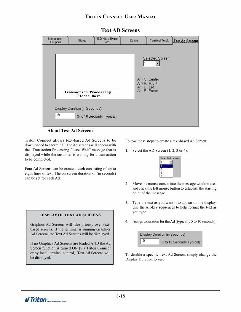
8-18
triton ConneCt User manUal
Text AD Screens
DISPLAYOFTEXTADSCREENS
Graphics Ad Screens will take priority over text-based screens. If the terminal is running Graphics Ad Screens, no Text Ad Screens will be displayed.
If no Graphics Ad Screens are loaded AND the Ad Screen function is turned ON (via Triton Connect or by local terminal control), Text Ad Screens will be displayed.
About Text Ad Screens
Triton Connect allows text-based Ad Screens to be downloaded to a terminal. The Ad screens will appear with the “Transaction Processing Please Wait” message that is displayed while the customer is waiting for a transaction to be completed.
Four Ad Screens can be created, each consisting of up to eight lines of text. The on-screen duration of (in seconds) can be set for each Ad.
Follow these steps to create a text-based Ad Screen:
1. Select the AD Screen (1, 2, 3 or 4).
2. Move the mouse cursor into the message window area and click the left mouse button to establish the starting point of the message.
3. Type the text as you want it to appear on the display. Use the Alt-key sequences to help format the text as you type.
4. Assign a duration for the Ad (typically 5 to 10 seconds):
To disable a specific Text Ad Screen, simply change the Display Duration to zero.

8-19
Chapter 8 -terminal parameters
About Terminal Totals
This tab lists significant terminal transaction totals. The values shown are read-only.
Total Debit Transactions
This is the total number of checking and savings account withdrawal transactions that have taken place since the last Day Close.
Total Credit Transactions
This is the total number of credit card withdrawal transactions since the last Day Close.
Total Balance Inquiries
This is the total number of balance inquiry transactions since the last Day Close.
Total Transfers Done
This is the total number of account transfer transactions since the last Day Close.
Total Debit Amount
This is the total monetary value of all Debit transactions that have taken place.
Total Credit Amount
This is the total monetary value of all Credit transactions that have taken place.
Terminal Totals
* NOTE *Terminal Totals are calculated from Day Close to Day Close. If Day Closes are not being performed, the totals are cumulative.

8-20
triton ConneCt User manUal
Changing Amounts
Use this screen to make changes to the cash amounts applicable to the listed parameters, by typing the values directly into the applicable text entry boxes.
Max.WithdrawalAmount
This is the maximum amount allowed per customer withdrawal transaction. It can be set from 1 to 999999 in increments of 1 and it must be an even multiple of the denomination that is in the cassette. The value is dollar amount only; no cents are allowed.
Whenever a withdrawal amount is entered, either through a Fast Cash selection or by user-defined entry, the amount is compared to the maximum withdrawal limit. If the amount is larger than the limit, an error message warns the user and displays the maximum allowable amount.
Follow these steps to change the maximum amount:
1. Click inside the Max Withdrawal Amount text box.
2. Enter the maximum withdrawal amount.
FastcashAmounts
These are common cash values offered to the customer as “quick” withdrawal amounts. Up to five fast cash amounts can be entered.
Follow these steps to change the Fast Cash amounts:
1. Click inside a Fastcash text box.
2. Enter the fast cash amount.
Denomination
This field varies depending upon the terminal type (single or multiple-cassette), and is normally a read-only field that indicates the denomination of the currency in the cassette(s).
Amounts
* NOTE *The maximum withdrawal amount DOES NOT override any maximum set by a network. The transaction will be sent to the network if the amount entered or selected is less than or equal to the maximum. The network must still approve the amount.
* NOTE *Fastcash amounts MUST be values that are multiples of the denomination. Other amounts will cause an error condition at the terminal.
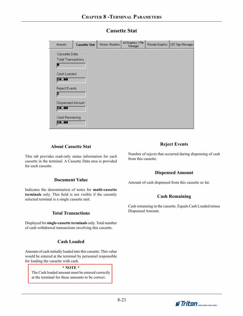
8-21
Chapter 8 -terminal parameters
Cassette Stat
* NOTE *The Cash loaded amount must be entered correctly at the terminal for these amounts to be correct.
About Cassette Stat
This tab provides read-only status information for each cassette in the terminal. A Cassette Data area is provided for each cassette.
Document Value
Indicates the denomination of notes for multi-cassette terminals only. This field is not visible if the curently selected terminal is a single cassette unit.
Total Transactions
Displayed for single-cassette terminals only. Total number of cash withdrawal transactions involving this cassette.
CashLoaded
Amount of cash initially loaded into this cassette. This value would be entered at the terminal by personnel responsible for loading the cassette with cash.
Reject Events
Number of rejects that occurred during dispensing of cash from this cassette.
Dispensed Amount
Amount of cash dispensed from this cassette so far.
Cash Remaining
Cash remaining in the cassette. Equals Cash Loaded minus Dispensed Amount.
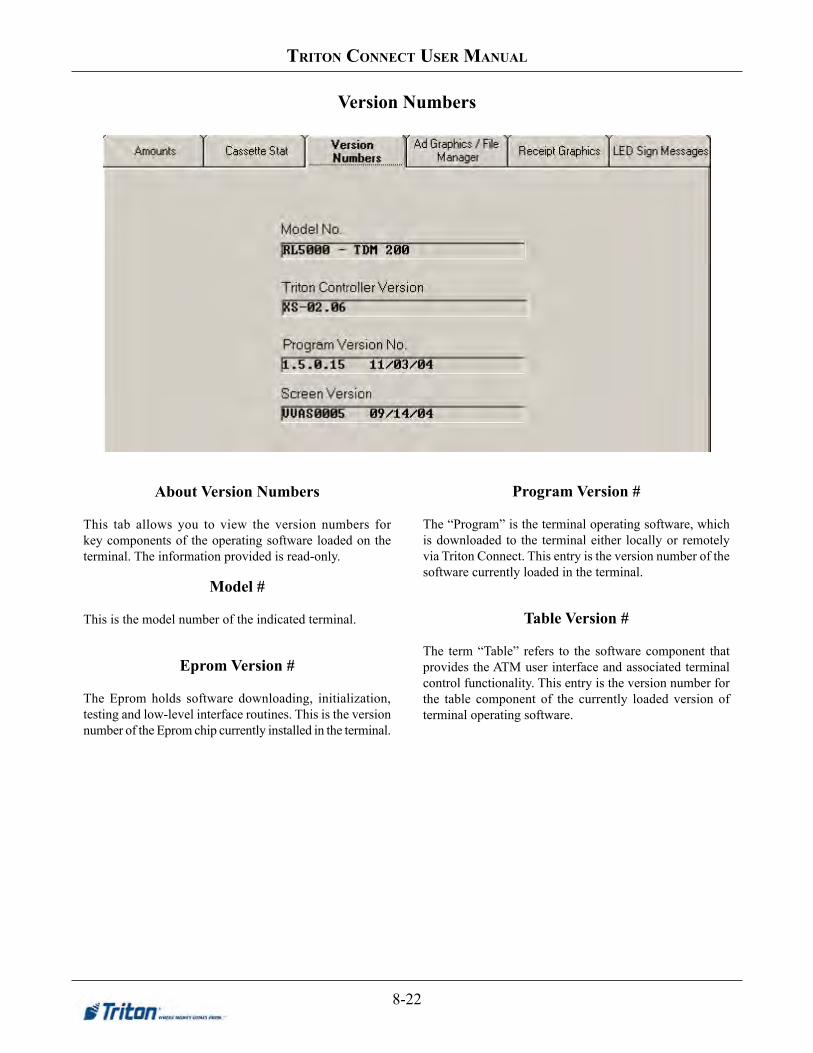
8-22
triton ConneCt User manUal
About Version Numbers
This tab allows you to view the version numbers for key components of the operating software loaded on the terminal. The information provided is read-only.
Model #
This is the model number of the indicated terminal.
Eprom Version #
The Eprom holds software downloading, initialization, testing and low-level interface routines. This is the version number of the Eprom chip currently installed in the terminal.
Program Version #
The “Program” is the terminal operating software, which is downloaded to the terminal either locally or remotely via Triton Connect. This entry is the version number of the software currently loaded in the terminal.
Table Version #
The term “Table” refers to the software component that provides the ATM user interface and associated terminal control functionality. This entry is the version number for the table component of the currently loaded version of terminal operating software.
Version Numbers

8-23
Chapter 8 -terminal parameters
ADGraphics/FileManager
* NOTE *To access AD Graphics for 32-bit terminals (RL/FT5000, RT2000, 98XX), the message to the right will appear on this screen. AboutAdGraphics/FileManager
This tab helps you control the display of Ad Graphics on a selected terminal. You will use it to:
1. Create ad graphics using the Ad Designer utility.
2. Enable or disable the display of ad graphics at the terminal.
3. Configure the memory used by the terminal to store graphics.
4. View graphics files currently loaded on the terminal.
5. Add, remove and overwrite graphics files.
6. Schedule graphic display times.
Creating Ad Graphics
The actual creation of Ad Graphics is handled by the Ad Designer function, which you can access form the Ad Graphics/File Manager screen by clicking the View/EditAd button:
The graphic creation functions will not be addressed in this chapter. Complete coverage can be found in Chapter 13, Ad Designer.
Enabling Ad Graphics
You can enable or disable the display of ad screen graphics at the terminal using this control:
Check the box to enable the display of ad screens at the terminal. Uncheck it to disable.
ConfiguringMemory
Follow these steps to select and format the terminal’s memory:
1. Select the memory card in the terminal you want to work with (Memory 1 or Memory 2) by clicking on the appropriate option button.

8-24
triton ConneCt User manUal
2. If the Available Memory window does not show a value, then the selected memory card has not been formatted. If this is the case, select the option to re-format the memory card.
3. If you want to reformat the selected memory card, make sure the corresponding check box is checked:
4. A warning message will appear asking you to confirm the re-format action:
Select Yes to confirm the re-format action.
Once the reformatting operation has been completed successfully, the appropriate value should show in Available Memory window. Ad Screen graphics can now be downloaded to the selected terminal.
ViewingFiles
Follow these steps to see the files currently loaded on the terminal:
1. Select the memory card whose contents you want to view:
2. Select the Show files currently loaded option. The current contents of the memory card are displayed in the text window:
3. To see the files that will remain on the terminal after the file download operation has taken place, select the Show files to be remaining after send operation option:
You will add and remove files from this list as necessary to make it reflect the contents you want for the selected memory card.
AddingFiles
Follow these steps to add a new graphics file to the selected memory card:
1. Select the memory card you want to add the file to:
2. Click the AddFile button:
* NOTE *Some Triton System products, such as the SuperScriptm terminal, must have its memory storage formatted via Triton Connect before use, using the ReformatMemoryCard1 option.

8-25
Chapter 8 -terminal parameters
* NOTE *Only .TCG files can be selected to send to terminals other than RL/FT5000 and RT2000 models. See Chapter 12 “Ad Graphics” for information on creating thees files.
A file browser will appear. Use it to locate and select the file you want to add:
Click OK to accept the selection. The file will be added to the list of files to remain:
3. Repeat the previous steps to add any additional files to the list. The files you choose will also be listed to the Files to be added list:
RemovingFiles
To remove a file that is currently loaded on the terminal, follow these steps:
1a. If the file is currently loaded on the terminal, select the file in the ‘Files to remain after Send Parameters’ list:
1b. If the file is scheduled to be added and you want to remove it, select the file in the ‘Files to be added’ list:
2. Click the RemoveFile button:
When you remove files that are currently loaded on the terminal, the files are listed in the ‘Files to be removed’ list:
If you change your mind about any file in this list, simply highlight it and click the RemoveFile button again. The file will be returned to the ‘Files to remain after Send Parameters’ list.
OverwritingFiles
If you want to overwrite the files currently stored in the selected memory card with the ones in the ‘Files to remain after Send Parameters’ list, check the box for the Overwrite existing files on terminal action:
If you choose not to overwrite files, the files you send will be added to those already stored in the affected memory card.

8-26
triton ConneCt User manUal
Scheduling Ad Graphic Display Times
Perform the following steps to schedule the display time for an add graphic:
1. Select file name in the ‘Files To Remain After Send Parameters’ list to highlight the file.
2. Click on the Schedule button. Select the time(s) that the ad screen will be scheduled for display on the terminal. (The Scheduling options are described next.)
Always. Selecting the Always option changes the color of the grid to green to indicate that the Ad Graphic is displayed at all times except when a transaction is taking place.
Never. Choosing the Never option changes the color of the grid to red to indicate the Ad Screen is never displayed.
SelectingaSpecificTime
Right or left clicking on a specific time will change the hour selected from green to red or red to green. The Ad Screen displays during the selected hour(s) highlighted in green. The Ad Screen will not displayed during the selected hour(s) that are highlighted in red.
FinalizingtheSchedule
Click the Apply button to set the scheduled time for the selected Ad Screen graphic. Click the OK button to return to Ad Graphics/File Manager main screen.

8-27
Chapter 8 -terminal parameters
About Receipt Graphics
This tab allows graphics created with any graphics application that supports BMP files to be formatted and downloaded to the terminal. The graphics can be printed on various receipt types produced by the terminal.
Receipt printer graphics are limited to monochrome (black/white) BMP files that have a maximum resolution of 384 dots wide by 384 dots high. The settings of the Receipt Graphics controls will determine how the printed graphic appears on the receipt.
The setup parameters are described below:
Enabling Receipt Graphics
You can enable or disable the printing of graphics on receipts using this control:
Click on the box to enable (check) or disable (unchecked) receipt graphic printing.
Receipt Graphics
* NOTE *To access Receipt Graphics for 32-bit terminals (RL/FT5000, RT2000, 98XX), the message to the right will appear on this screen.
ReceiptGraphicConfiguration
Follow these steps to configure the terminal’s memory:
1. Select a memory card (Memory 1 or Memory 2) to view the current graphic(s) stored in the terminal’s memory.
2. Select a receipt from the Receipt Type list.
The name of the receipt graphic that is currently loaded (if any) at the terminal is displayed in the Graphic Filename box, as in this example:

8-28
triton ConneCt User manUal
If there is no graphic currently loaded for the selected receipt type, the Graphic Filename will be blank.
3. To load a graphic for the selected receipt, click the SelectFile button and use the file dialog box to locate and select the file you want to use.
An image of the file will appear in the Preview window:
4. If you change your mind and want to remove the file, click the RemoveFile button.
5. Select a justification setting for the receipt graphic.
6. Choose the location for the graphic on the receipt.
7. Repeat Steps 2-6 for another receipt type, as necessary.
8. Overwrite the existing graphic on the selected memory card with the new graphic by checking ‘Overwrite Existing Files on Terminal.’

8-29
Chapter 8 -terminal parameters
Advanced Settings
* NOTE *Each parameter description is written to describe the ‘checked’ state of the parameter. For example, the parameter ‘Balance inquiries enabled’ is enabled when the checkbox is checked:
About Advanced Settings
This screen provides access to additional terminal parameters. The parameters are extremely sensitive functions that should not be altered unless you understand the affect on terminal operation or are instructed to enable a feature by your Host Processor or Technical Support personnel!
Check the box next to the parameter you want to change.
Balance Inquiries Enabled
Check this option to enable the terminal to present an account balance transaction option to the customer.
Savings Account Transactions Enabled
Check this option to enable the terminal to present a savings account withdrawal transaction option to the customer.
Credit Card Transactions Enabled
Check this option to enable the terminal to present a credit card withdrawal transaction option to the customer.
Transfers Enabled
Check this option to enable the terminal to present a funds transfer transaction option to the customer.
Include Comms Header in Processor Request Message
Check this option to enable the terminal to include the Communication Header in all request messages to the Host Processor. An example would be a request to process a customer withdrawal transaction.
The actual Comms Header (if one is required by the Host Processor), is entered at the terminal during its setup and configuration.

8-30
triton ConneCt User manUal
Include Terminal Status in Processor Request Message
Some host processors may wish to have status information included in each request message received from a terminal. Monitoring this status can provide important information about the operational readiness of the terminal. Check this option to provide this information to the host processor.
Return Terminal Total to Processor
Check this option to enable the terminal to send the terminal totals to the host processor during a close operation.
Ignore EOT Character from Processor at End of Transaction
If this option is checked the terminal will not look for the End-of-Transaction (EOT) character at the conclusion of a transaction. Use of this option is processor-specific.
Allow Extended Transaction Amounts
This is a READ-ONLY display of the current state of this feature on the terminal. It echoes the value set in the Management Functions of the terminal.
Dispense Opposite Cassette Side
This is a READ-ONLY display of the current state of
this feature on the terminal. It echoes the value set in the Management Functions of the terminal. The checkbox should only be checked if the affected terminal is a rear-dispensing model.
LockCassettes
Check this option to lock the note cassettes in the chassis of the terminal’s dispensing mechanism.
Allow any Bill Denominations
This option is provided primarily for international currency value support. It enables the terminal to accept non-U.S. standard note denomination values.
Cassette(A-D)isIn-Service
Use the checkboxes in this section to control the service-status of each note cassette installed in the terminal. Note that there are four checkboxes, supporting the maximum number of cassettes that may be installed in a terminal. To place a cassette In-Service, make sure the corresponding checkbox is checked before initiating the “Send Parameters” command. Note: Cassettes can only be enabled if the proper cassette loading procedure has been followed at the terminal.
If the terminal has fewer than four cassettes installed, the remaining options will have no affect on its operation; however, you may observe that the state of these unused options changes to match that of the active options. For example, un-checking both Cassette A and Cassette B on a two-cassette terminal will automatically uncheck the Cassette C and Cassette D options.
* NOTE *The Cassette Service checkboxes will only be visible on the Advanced Settings tab when the selected terminal is a multi-cassette unit.

8-31
Chapter 8 -terminal parameters
E-Flags
AboutE-Flags
E-FlagsareAdvancedfeaturesforfutureuse.DO NOT make any adjustments to these settings!

8-32
triton ConneCt User manUal
Changing Passwords
Clicking the Change Terminal Master Password button brings up the following:
Passwords
Enter the current password in either case. If this entry is accepted, you’ll be allowed to enter a new password, which will take effect after the next scheduled parameter download to the terminal.
You can not change/reset the password if you do not know the current password.
You can remotely change the terminal Master and Administrative passwords from this screen.
* NOTE *This function applies to Z-180 processor units (Models 8100/9100/9600/9700 etc). To change passwords for X-Scale units (Models RL/FT/RT), you must use the “CONTROL” function, extended parameters > misC option.

8-33
Chapter 8 -terminal parameters
AboutSurchargeConfiguration
Use the controls on this tab to enable or disable surcharging, enter a surcharge amount or percentage, determine where the surcharge message will be displayed during the transaction (beginning or end of transaction), and select and configure the surcharge message itself.
The specific surcharging requirements are determined by your processor or other appropriate regulatory agency.
SurchargeConfiguration
Follow these steps to configure the surcharge settings:
1. Enable surcharging. Click the Surcharge Enabled listbox and select the Enabled option to turn surcharging ON. Select Disabled to turn surcharging OFF.
Surcharge
** IMPORTANT **If a fixed surcharge amount is used and the surchargepercentWILLNOTbeused,youmustensure the surcharge comparison option is set to GREATERandthesurchargepercentissettozero(0).Thiswillensurethatonlythefixedsurchargeamountvaluewill bedisplayed to the customer.Failuretodosocancauseanincorrectsurchargevaluetobereported.
2. Set surcharge amount. If a fixed surcharge amount will be applied to transactions, click inside the Surcharge Amount textbox and enter the amount. Value may be from $0.00 to $999,999.99 inclusive.
3. ModifysurchargemessagetextusingtheWill/Mayselection. This lets the customer know if they “may” or “will” be charged a fee for processing a transaction.

8-34
triton ConneCt User manUal
4. Set surcharge percentage. If the surcharge will be calculated as a percentage of the transaction amount, click the Surcharge Percent list and select the required percentage (0 to 99 percent)
5. Choose surcharge screen location. The SURCHARGE LOCATION option lets you determine when the customer is presented with the surcharge message.
Place a check in the checkbox to display the surcharge message AFTER the customer has selected a Fast Cash value or entered a custom withdrawal amount. Remove the check to display the surcharge message BEFORE the customer enters a withdrawal amount (the message will appear as soon as the customer removes their card from the card reader).
6. ModifysurchargemessagetextusingtheLesser/Greater selection. This is used for surcharging systems that calculate a surcharge based on a comparison between a fixed surcharge and a percentage-based surcharge.
7. Select the surcharge screen that will be displayed on the terminal. Click the Surcharge Screen listbox and select a screen. The message text for this screen will appear in the preview window.
8. ClickHereforSurchargeScreenDetails.This screen summarizes the surcharge settings and screen selected.
** IMPORTANT **If the processor or other authority requires that the surcharge be the lesser of either the surcharge amount or surcharge percentage, select the LESSER option. If the surcharge must be the greater of either the surcharge amount or surcharge percentage, select the GREATER option.
* NOTE *Text on the Surcharge screen is read-only and can not be edited.

8-35
Chapter 8 -terminal parameters
CreateCustomSurchargeScreen(new)
This new feature option allows user to create a Custom Surcharge Screen. This option (Surcharge Screen #12) is only available if the terminal supports UDS (User Defined Surcharge) screens.
* NOTE *Currently this option is only available on 8-bit terminals (91XX,.97XX, etc) AND only available with Mexico software.
To modify the Customer Surcharge Screen / User Defined Surcharge Screen, click the button for “Surcharge Screen Details”. The following screen details appear.
This screen is used for creating the Custom Surcharge screen / User Defined Surcharge screen. The user can import and export screens to file so that the same text may be used on multiple ATMs.
Select the alignment for the text.
Load .CSS
Save .CSS
Text is limited to nine (9) lines of thirty-two (32)
characters across.

8-36
triton ConneCt User manUal
Right-click in one of the Text screens brings up a menu with an option to view. Selecting this option will display a window showiing what the screen will look like on the ATM. Below is an example of the screen:

8-37
Chapter 8 -terminal parameters
Use this screen to enable or disable Call Back and configure the parameters the terminal will use when placing calls to the Triton Connect host PC.
Triton Connect Call Back
This function determines whether or not the terminal will return a call after first receiving an initiating call from a Triton Connect host computer.
TC Max Retries
Calls from the terminal to the Triton Connect host computer are made in blocks. Each block actually consists of multiple attempts to reach the host computer, using the Triton Connect primary and backup phone numbers.
During each block, the terminal will place a call to the primary number; if there is no answer in 60 seconds, the call will be attempted using the backup number (if one is available).
If there is no answer using the backup number within 60 seconds, or there is no backup number available, the terminal will repeat the cycle, returning to the primary number, then the backup.
If there is still no answer after two calls to the primary number and two calls to the backup number, the terminal will pause for a period of time established by the Triton Connect Redial Delay parameter (described next), then will begin the communications attempt again with the next call block.
The cycle of call blocks will be repeated for the number of times established in the Triton Connect Max Retries setting before attempts to reach the host computer are abandoned.
Triton Connect Settings
* NOTE *If Call Back is disabled, the EPROM access code must be entered in the terminal setup.
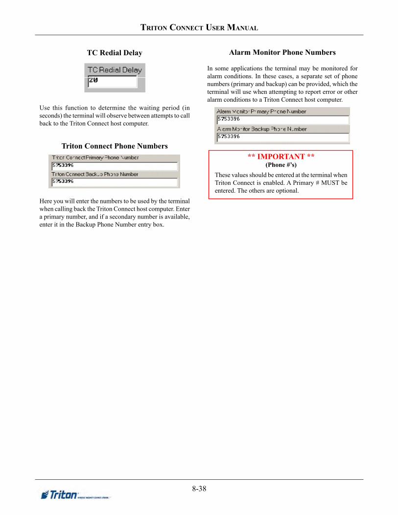
8-38
triton ConneCt User manUal
TC Redial Delay
Use this function to determine the waiting period (in seconds) the terminal will observe between attempts to call back to the Triton Connect host computer.
Triton Connect Phone Numbers
Here you will enter the numbers to be used by the terminal when calling back the Triton Connect host computer. Enter a primary number, and if a secondary number is available, enter it in the Backup Phone Number entry box.
Alarm Monitor Phone Numbers
In some applications the terminal may be monitored for alarm conditions. In these cases, a separate set of phone numbers (primary and backup) can be provided, which the terminal will use when attempting to report error or other alarm conditions to a Triton Connect host computer.
** IMPORTANT ** (Phone#’s)
These values should be entered at the terminal when Triton Connect is enabled. A Primary # MUST be entered. The others are optional.

8-39
Chapter 8 -terminal parameters
Control
DAYCLOSEThe Day Close report shows the cumulative value of all transactions (withdrawals, transfers, balance inquiries) performed by the ATM since the previous Day Close. The report also shows the corresponding Host totals, allowing you to compare the ATM totals against the Host processor records.Perform a Day Close once each business day. Because the Host Processor also performs a business Day Close for the ATM, you should perform the close at the same time each day at the time specified by your Host Processor. This will help ensure the Day Close reports reflects the Host’s current business day totals for your ATM.
This screen enables you to control various parameters associated with close scheduling, alarm threshold conditions, and terminal monitoring and status reporting.
The following sections provide descriptions of the various parameters.
Extended Parameters* This option appears for 32-bit terminals (RL/FT5000, RT2000, 98XX) to configure specific parameters. See pages 43through55fordescriptionofoptions
Enable Scheduled Close
Check this option to enable the terminal Day Close function.
Close Report Time
Once you’ve enabled the terminal to automatically generate a Day Close, specify the time of day at which the close is to take place. Use the controls to choose an hour, minute and AM or PM value.
LowCurrencyCheck
Use this function to enable or disable (as appropriate) the low currency checking feature of the terminal. If unchecked, the terminal will go Out of Service when the level of currency in the cassette drops below a certain threshold (see the applicable operations manual for the terminal for more information). If the function is checked, the terminal will not go out of service until the cassette is empty.
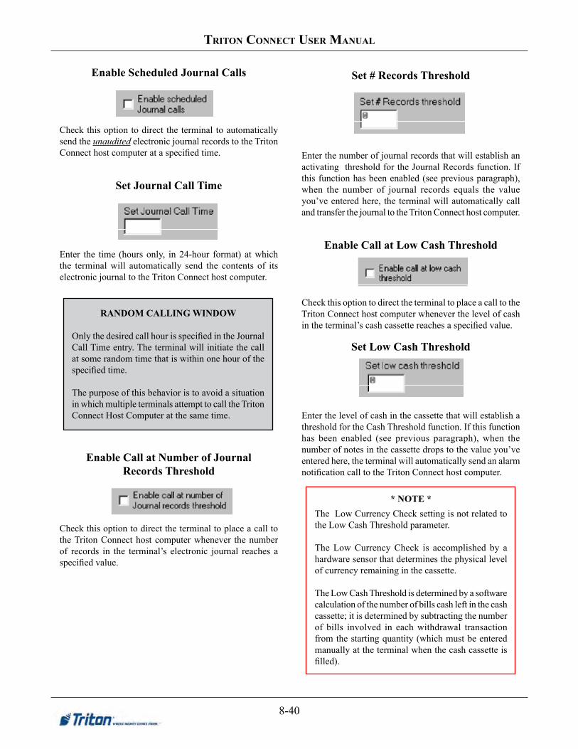
8-40
triton ConneCt User manUal
Enable Scheduled Journal Calls
Check this option to direct the terminal to automatically send the unaudited electronic journal records to the Triton Connect host computer at a specified time.
Set Journal Call Time
Enter the time (hours only, in 24-hour format) at which the terminal will automatically send the contents of its electronic journal to the Triton Connect host computer.
Enable Call at Number of Journal Records Threshold
Check this option to direct the terminal to place a call to the Triton Connect host computer whenever the number of records in the terminal’s electronic journal reaches a specified value.
Set # Records Threshold
Enter the number of journal records that will establish an activating threshold for the Journal Records function. If this function has been enabled (see previous paragraph), when the number of journal records equals the value you’ve entered here, the terminal will automatically call and transfer the journal to the Triton Connect host computer.
EnableCallatLowCashThreshold
Check this option to direct the terminal to place a call to the Triton Connect host computer whenever the level of cash in the terminal’s cash cassette reaches a specified value.
SetLowCashThreshold
Enter the level of cash in the cassette that will establish a threshold for the Cash Threshold function. If this function has been enabled (see previous paragraph), when the number of notes in the cassette drops to the value you’ve entered here, the terminal will automatically send an alarm notification call to the Triton Connect host computer.
RANDOMCALLINGWINDOW
Only the desired call hour is specified in the Journal Call Time entry. The terminal will initiate the call at some random time that is within one hour of the specified time.
The purpose of this behavior is to avoid a situation in which multiple terminals attempt to call the Triton Connect Host Computer at the same time.
* NOTE *The Low Currency Check setting is not related to the Low Cash Threshold parameter.
The Low Currency Check is accomplished by a hardware sensor that determines the physical level of currency remaining in the cassette.
The Low Cash Threshold is determined by a software calculation of the number of bills cash left in the cash cassette; it is determined by subtracting the number of bills involved in each withdrawal transaction from the starting quantity (which must be entered manually at the terminal when the cash cassette is filled).

8-41
Chapter 8 -terminal parameters
HEARTBEAT MESSAGEThe HEARTBEAT MESSAGE feature is designed to provide a means of reporting communications system status to the host processor.
Status reporting by dial-up ATMs is now the norm, but the single most important feature that cannot be monitored is the communications status. The absence of transactions from a particular terminal can means one of two things. Usually the lack of calls indicates nothing more than a slow period. Sometimes, though, a piece of the communications system will fail and inhibit any calls from being made. The host has no way of determining which scenario is occurring in any kind of real-time mode. The Heartbeat Message overcomes this limitation.
When this feature is ENABLED, the terminal will call the host after a period of inactivity. During this call, the terminal will request a COMMS KEY DOWNLOAD (the normal configuration download request), and will report status (if the STATUS MONITORING function is ENABLED). This allows the host to determine if a particular terminal is still in operation, even though it may not be performing any transactions at the time.
Once the Heartbeat Message call feature is enabled at the terminal, an internal timer will be initialized to the number of minutes set in the DELAY PERIOD parameter at system power-up and after a reset. This timer is restarted each time a call is made to the host. A call to the host is defined as any transaction, including financial, balancing and configuration that actually communicates with the host to the point that the Terminal ID is recognized. A customer transaction that is declined will reset the timer, while a call that fails because the host phone number was busy would not.
LinesPerReceipt
This function sets the minimum print length (in lines) of the receipt provided to the customer after each transaction. NOTE: Changing the print length to less than 35 lines will prevent the receipt from exiting the front of the terminal. This could cause paper jams that could result in printer damage!
Receipt Option Enabled
When this option is checked the customer will be given the option of receiving or not receiving a printed receipt at the conclusion of the transaction.
StayinServiceWhenReceiptPaperisLow
Check this option to force the terminal to remain in operation despite a low receipt paper condition.
Allow Heartbeat to be Enabled
Check this option to make the Heartbeat option visible to the operator of the terminal. The Heartbeat option will appear in the applicable Management Functions menu area of the terminal. Use the Enable Heartbeat function (described next) to enable or disable the function.
EnableHeartbeat/DelayPeriod
If the Allow Heartbeat to be Enabled option has been checked (thus making the feature accessible at the terminal), you can enable this option. Enter the number of minutes that must expire before a Heartbeat message will be sent by the terminal. NOTE: The Delay Period MUST be greater than Zero (0) or a software download will be required to clear the machine’s “Out of Service “ condition.
EnableHeartbeatatSpecificTime
If the Enable Heartbeat at Specific Time has been checked, you can enter a specific time when a heartbeat message will be sent by the terminal.
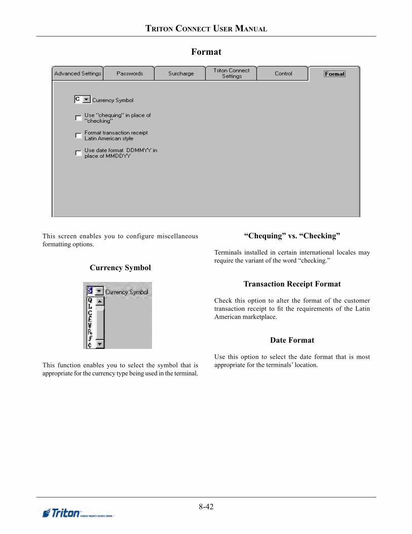
8-42
triton ConneCt User manUal
This screen enables you to configure miscellaneous formatting options.
Currency Symbol
This function enables you to select the symbol that is appropriate for the currency type being used in the terminal.
“Chequing”vs.“Checking”
Terminals installed in certain international locales may require the variant of the word “checking.”
TransactionReceiptFormat
Check this option to alter the format of the customer transaction receipt to fit the requirements of the Latin American marketplace.
DateFormat
Use this option to select the date format that is most appropriate for the terminals’ location.
Format

8-43
Chapter 8 -terminal parameters
When the currently selected terminal is a Model RL5000, FT5000, RT2000, or 98XX-series ATM, the Control tab provides the Extended Parameters and Out of Service Settings options.
Out of Service Settings
Clicking this button provides access to enable the terminal to go “Out of Service” for a Printer error.
Extended Parameters
Clicking this button provides access to a sub-system of dialogs that enable you to configure specific parameters. This feature is available in XScale and X2 units only.
The dialogs are organized into the following parameter areas:
• Ad Data
• Couponing
• Misc.
• News Ticker (N/Aatthistime)
• Optional Screens
The following sections provide descriptions of the various parameter areas.
Extended Parameters
** IMPORTANT **After completing the required parameter changes, click the Save Changes button to save the current settings and return to the Terminal Parameters main dialog. Use the Send Parameters function to send the new settings to the selected terminal(s).

8-44
triton ConneCt User manUal
The Extended Parameters - Ad Data tab enables you to perform the following ad configuration actions:
1. Add and Remove Ads.
2. Configure Ad Display Times, Duration and Location.
3. Configure Ad Sequence.
4. Select a Screen File.
Add and Remove Ads
Follow these steps to add an ad to the Active Ads list:
1. Check the Terminal Data Directory list. If the ad you want is located in the list, click the entry to highlight it and then click the Activate Ad button to add the ad to the Active Ads list.
To highlight a group of ads, click once on the first ad, then hold down the SHIFT key while clicking on the last ad in the group. This will highlight the first ad, the last ad and any ads in between.
To highlight multiple ads that do not fall neatly into a group, hold down the CTRL key while you click on any ad anywhere in the list.
2. If the ad you want is not located in the list, click the Add Ad button to bring up a browse dialog:
Extended Parameters - Ad Data

8-45
Chapter 8 -terminal parameters
Browse to the location of the ad you want and click on the filename to highlight it. Click Open to accept the selection and return to the Ad Data window. The entry is added to the terminal data directory and automatically added to the Active Ads list.
3. When you add an ad to the Active Ads list the scheduling, duration and ad location controls appear. Configure the ad display times, duration and location. (See the section Configure Ad Display Times, Duration and Location for instructions.)
Follow these steps to remove an ad from the Active Ads list:
1. Locate the ad you want to remove in the Active Ads list and click on the entry to highlight it.
2. Click the Remove Ad button to remove the ad from the Active Ads list.
ConfigureAdSequence
The order in which multiple ads are displayed on the terminal’s screen is determined by their arrangement in the Active Ads list. You can control this order by moving ads up and down in the list.
Follow these steps to configure ad sequence:
1. If you want a particular ad to be shown before other ads in the list, click on the ad in the Active Ads list to highlight it, then click the Move Up button to place the ad above the other items:
2. If you want a particular ad to be shown after other ads in the list, click on the ad in the Active Ads list to highlight it, then click the Move Down button to move the ad below the other items.
ConfigureAdDisplayTimes,Duration,andLocation
Performing either of the following actions will show the ad display times, duration and location controls:
1. Add an ad to the Active Ads list.
2. Highlight an entry in the Active Ads list and click the View Schedule/Field button:
Follow these steps to configure ad display times, duration and location for the currently selected ad in the Active Ads list:
1. Active Hours. The Active Hours schedule shows a checkbox for each hour of the day. By default, newly added ads are scheduled for 24-hour display, therefore the checkbox for each hour is checked.
To change the display times for the current ad, remove the checkmarks for those hours in which you don’t want the ad to be displayed, and place a checkmark in those checkboxes for hours in which you want the ad to be displayed. Click the Apply button to accept the changes.
2. Duration. This is the length of time (in seconds) the ad will be displayed. By default, a value of zero (0) is displayed in the Duration textbox. To set the time, click inside the Duration textbox and enter a duration in seconds, between 0 and 120. If the ad is a video and 0 is selected, the ad will be displayed for the entire playing time of the video. Click the Apply button to accept the changes.

8-46
triton ConneCt User manUal
3. Active Field. This setting specifies where the ad graphic will be displayed and/or printed. To configure the location for the current ad, click inside the Active Field to view the location options:
• None
• Advertisement
• Logo
• Receipt Graphic
Click the required option, then click the Apply button to accept the choice.
4. When clicked, the Apply button becomes the Done button. Click the Done button to return to the main Ad Data window.
SelectaScreenFile
The Screen File specifies the appearance and functionality of the screens that are displayed to the customer at the terminal.
Follow these steps to select a Screen File:
1. Check the Terminal Data Directory list. If the Screen File you want is located in the list, click the entry to highlight it and then click the ActivateScreenFile button. The selected Screen File name is shown next to the button.
2. If the Screen File you want is not located in the list, click the AddScreenFile button to bring up a browse dialog.
Browse to the location of the Screen File you want and click on the filename to highlight it. Click Open to accept the selection and return to the Ad Data window. The selected Screen File name is shown next to the button.
Graphics are stored in Flash memory - RAM is same as on
a personal computer.
RAMMemory-Disk/FlashSpace* NOTE *
Screen files must be a properly formatted *.TSM file.

8-47
Chapter 8 -terminal parameters
GRAPHIC SIZES
Graphics are displayed in designated fields in the display. Optimize display graphics by creating them in sizes that fit their intended use. Graphic dimensions are in pixels.
X-SCALEUNITS(RL/FT5000/RT2000
FULL SCREEN - 636 X 476LOGO - 310 X 85TRANSACTION AD - 636 X 260BANNER - 205 X 56HEADER - 636 X 90WELCOME AD - 310 X 385
COUPON GRAPHIC (TOP OR BOTTOM ONLY) - 450 X 225 (.BMP only)COUPON GRAPHIC (TOP AND BOTTOM) - 320 X 160 (.BMP ONLY)RECEIPT GRAPHIC - 480 X 120 (.BMP only)
X2UNITS(RL2000orX2-MIGRATEDRL/FT5000/RT2000(W/10.4”DISPLAY)
5.7”DISPLAY(RL2000) 8.0”DISPLAY(RL2000)/10.4”DISPLAY
FULL SCREEN AD - 636 X 476TRANSACTION AD - 636 X 260TRANSACTION AD - 636 X 475RECEIPT GRAPHIC - 480 X 120 (.BMP only)
HEADER - 636 X 90WELCOME AD - 310 X 385FULL SCREEN AD - 636 X 476TRANSACTION AD - 636 X 260RECEIPT GRAPHIC - 480 X 120 (.BMP only)
* COUPON GRAPHIC (TOP OR BOTTOM - ONLY) - 450 X 225 (.BMP ONLY)
* COUPON GRAPHIC (TOP AND BOTTOM) - 320 X 160 (.BMP ONLY)
* Applies for any X2 display size.

8-48
triton ConneCt User manUal
GRAPHICEXAMPLES

8-49
Chapter 8 -terminal parameters
Extended Parameters - Couponing
Coupons are used to notify customers of awards, prizes, sales, or other promotional opportunities. The Extended Parameters - Couponing tab enables you to perform the following coupon configuration actions:
1. Select Coupon Type.
2. Set Minimum and Maximum Levels.
3. Enter a Random Percentage.
4. Enter a Coupon Prompt.
5. Enable Award Based on ISO Properties.
6. Configure Printed Coupon Message, Graphic and Layout.
7. Configure Dispensed Coupon Cassette and Number of Dispenses.
Select Coupon Type
There are two types of coupons that can be delivered to the customer: Printed or Dispensed. To configure the settings for a coupon you must first select the coupon type. You can choose to configure settings for as many as four Printed and two Dispensed coupon types per terminal.
Follow these steps to select the coupon type:
1. Click the coupon type drop-down list.
Printed0. This is the first of four available printed coupon types. Printed coupons are delivered to the customer via the receipt printer.
Printed(1-3). Additional printed coupon selections.
Dispensed0. This is the first of two available dispensed coupon types. Dispensed coupons are dispensed from one or more of the note cassettes.
Dispensed1. Additional dispensed coupon.
2. Select a coupon type. Set the coupon parameters as required.

8-50
triton ConneCt User manUal
SetMinimumandMaximumLevels
The Minimum Level parameter represents the minimum withdrawal amount that will trigger the printing or dispensing of a coupon. The Maximum Level parameter represents the maximum amount that will trigger the printing or dispensing of a coupon.
Follow these steps to set the minimum withdrawal amount for the currently selected coupon type:
1. Click inside the Minimum Level textbox.
2. Enter a value. The value must be at least as large as the Multiple Amount parameter, and no greater than the Maximum Cash parameter.
If the customer performs a successful withdrawal transaction for an amount equal to or greater than this amount, and less than or equal to the Maximum Withdrawal Amount parameter, a coupon will be printed or dispensed (as determined by the Coupon Type selected).
Follow these steps to set the maximum withdrawal amount for the currently selected coupon type:
1. Click inside the Maximum Level textbox.
2. Enter a value. The value must be at least as large as the Multiple Amount parameter, and no greater than the Maximum Cash parameter.
If the customer performs a successful withdrawal transaction for an amount equal to or greater than the Minimum Amount parameter and less than or equal to the Maximum Withdrawal Amount parameter, a coupon will be printed or dispensed (as determined by the Coupon Type selected).
Enter a Random Percentage
This function sets the frequency at which random prize coupons will be awarded (printed or dispensed, as applicable). The random coupon is won by a random number of transactions of any type. The winning percentage can be set from 0 to 100%. For example, if the winning percentage is set to 10%, then 1 out of every 10 transactions will be awarded a prize.
Follow these steps to enter a random award percentage value:
1. Click inside the Random Percentage textbox.
2. Enter the random winning percentage, from 0 to 100%.
Enter a Coupon Prompt
The prompt is a brief message that appears on screen when a customer is given a coupon. It’s primary purpose is to inform the customer of the presence of the coupon, so that it may be retrieved.
Follow these steps to enter the coupon prompt message:
1. Click inside the Prompt textbox.
2. Enter a brief message to serve as a prompt to the customer to retrieve the coupon.
Enable Award Based on ISO Properties
Use this function to enable the award of coupons to customers based on the detection of a particular ISO Number when the customer’s ATM card is scanned. Note: the ISO Number must have the Award Coupon action selected.
Follow these steps to enable coupon award based on ISO Properties:
To enable the function, click the Award Based on ISO Properties checkbox to place a checkmark in the box.
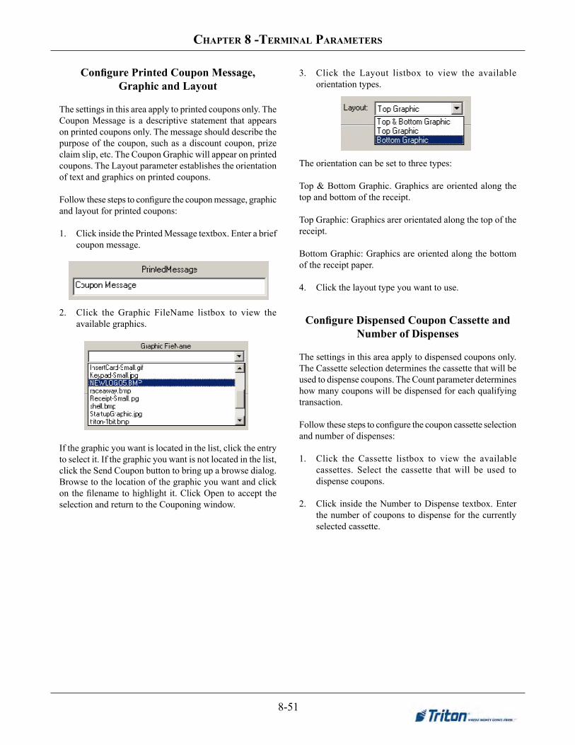
8-51
Chapter 8 -terminal parameters
ConfigurePrintedCouponMessage,GraphicandLayout
The settings in this area apply to printed coupons only. The Coupon Message is a descriptive statement that appears on printed coupons only. The message should describe the purpose of the coupon, such as a discount coupon, prize claim slip, etc. The Coupon Graphic will appear on printed coupons. The Layout parameter establishes the orientation of text and graphics on printed coupons.
Follow these steps to configure the coupon message, graphic and layout for printed coupons:
1. Click inside the Printed Message textbox. Enter a brief coupon message.
2. Click the Graphic FileName listbox to view the available graphics.
If the graphic you want is located in the list, click the entry to select it. If the graphic you want is not located in the list, click the Send Coupon button to bring up a browse dialog. Browse to the location of the graphic you want and click on the filename to highlight it. Click Open to accept the selection and return to the Couponing window.
3. Click the Layout listbox to view the available orientation types.
The orientation can be set to three types:
Top & Bottom Graphic. Graphics are oriented along the top and bottom of the receipt.
Top Graphic: Graphics arer orientated along the top of the receipt.
Bottom Graphic: Graphics are oriented along the bottom of the receipt paper.
4. Click the layout type you want to use.
ConfigureDispensedCouponCassetteandNumber of Dispenses
The settings in this area apply to dispensed coupons only. The Cassette selection determines the cassette that will be used to dispense coupons. The Count parameter determines how many coupons will be dispensed for each qualifying transaction.
Follow these steps to configure the coupon cassette selection and number of dispenses:
1. Click the Cassette listbox to view the available cassettes. Select the cassette that will be used to dispense coupons.
2. Click inside the Number to Dispense textbox. Enter the number of coupons to dispense for the currently selected cassette.

8-52
triton ConneCt User manUal
The Extended Parameters - Misc tab allows you to perform the following configuration actions:
1. Change Default Language.
2. Change Default Transaction.
3. Change Default Account.
4. Change Protocol Type.
5. Change Message Type.
6. View User List.
7. Schedule Reboot.
8. Delete users and/or modify user name (32-bit terminals only)
ChangeDefaultLanguage
The Default Language will be used to display/print customer and management reports and receipts.
The default language is the language that is initially displayed on customer transaction screens. This language will be used for all screens unless changed by the customer. In most cases you will select a default language based on the terminal’s location and customer language considerations. Usually, the default language will suffice for the majority of your intended customers.
In other cases you may want to give customers the option of selecting a different language than the default language. You can give customers this option by providing a language selection screen, which let’s them select their language of choice.
When an optional language is selected, the ATM uses the language in all transaction screens for the current customer’s session only, returning to the default language for subsequent customers.
Follow these steps to change the Default Language:
1. Click the Default Language listbox to view the available languages.
Available languages include: English, French and Spanish, but may include other languages, depending upon the terminal software in use.
2. Click the language you want to use.
Extended Parameters - Misc
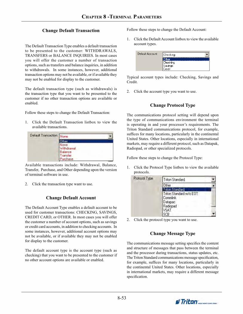
8-53
Chapter 8 -terminal parameters
Change Default Transaction
The Default Transaction Type enables a default transaction to be presented to the customer: WITHDRAWALS, TRANSFERS or BALANCE INQUIRIES. In most cases you will offer the customer a number of transaction options, such as transfers and balance inquiries, in addition to withdrawals. In some instances, however, additional transaction options may not be available, or if available they may not be enabled for display to the customer.
The default transaction type (such as withdrawals) is the transaction type that you want to be presented to the customer if no other transaction options are available or enabled.
Follow these steps to change the Default Transaction:
1. Click the Default Transaction listbox to view the available transactions.
Available transactions include: Withdrawal, Balance, Transfer, Purchase, and Other depending upon the version of terminal software in use.
2. Click the transaction type want to use.
Change Default Account
The Default Account Type enables a default account to be used for customer transactions: CHECKING, SAVINGS, CREDIT CARD, or OTHER. In most cases you will offer the customer a number of account options, such as savings or credit card accounts, in addition to checking accounts. In some instances, however, additional account options may not be available, or if available they may not be enabled for display to the customer.
The default account type is the account type (such as checking) that you want to be presented to the customer if no other account options are available or enabled.
Follow these steps to change the Default Account:
1. Click the Default Account listbox to view the available account types.
Typical account types include: Checking, Savings and Credit.
2. Click the account type you want to use.
Change Protocol Type
The communications protocol setting will depend upon the type of communications environment the terminal is operating in and your processor’s requirements. The Triton Standard communications protocol, for example, suffices for many locations, particularly in the continental United States. Other locations, especially in international markets, may require a different protocol, such as Datapak, Radiopad, or other specialized protocols.
Follow these steps to change the Protocol Type:
1. Click the Protocol Type listbox to view the available protocols.
2. Click the protocol type you want to use.
Change Message Type
The communications message setting specifies the content and structure of messages that pass between the terminal and the processor during transactions, status updates, etc. The Triton Standard communications message specification, for example, suffices for many locations, particularly in the continental United States. Other locations, especially in international markets, may require a different message specification.

8-54
triton ConneCt User manUal
The communications message setting will depend upon your processor’s communications requirements.
Follow these steps to change the Message Type:
1. Click the Message Type listbox to view the available message formats.
2. Click the message type you want to use.
Schedule Reboot
A periodic scheduled reboot of PC-based units is recommended at least once a week. Use these fields to Enable the Scheduled reboot and set the time for the reboot of the terminal.
ViewUserListPasswords restrict management functions access to designated personnel. Each authorized user will be assigned a password, a 2-digit ID code, and a Username. The ID code and password are entered together to gain access to the terminal management functions, while the Username provides a “friendly” name that refers to the currently logged in user. The Username can be up to 40-characters long.
The User List shows the ID code and corresponding Username for each User on the terminal.
Delete/ModifyUser(new)(32-bit terminals only)
To DELETEaUser(NOTMASTER) - Highlight a User and then click on the Delete User. The user will be removed from the ATM.
To Modify a User’s name or change a User’s password - Highlight a User and click on the ModifyUser. The following screen will appear:
Change the User’s name and/or password and select “Apply”. The changes will be applied to the ATM.
* NOTE *MasterandUserpasswordsmaybemodifiedIF the terminalisrunningsoftwareversion1.8.2ornewer!

8-55
Chapter 8 -terminal parameters
Triton Connect adds the ability to import user passwords to send to the ATM. This could be used to reduce typographical errors or re-typing the passwords if they will be sent to several ATMs or groups of ATMs at different times. The format ofthe file is one user’s data per line containing the User ID, Username, and the password, each separated by a comma. The file can be created in Notepad or any standard text editor.
To use this feature, perform the following steps:
1. Open the Triton Connect Terminal Manager
2. Click the Terminal Data menu and select Set Terminal prameters.
3. Select the desired ATM and click View Parameters.
4. Navigate to the Control tab.
5. Click the Extended Parameters button.
6. Navigate to the Misc tab.
7. Click Import From File in the User List area.
8. Browse for the file, select it, and click Open.
9. Click Save Changes.
10. Click Send Parameters to schedule the call to the ATM.
Import ATM Passwords from File
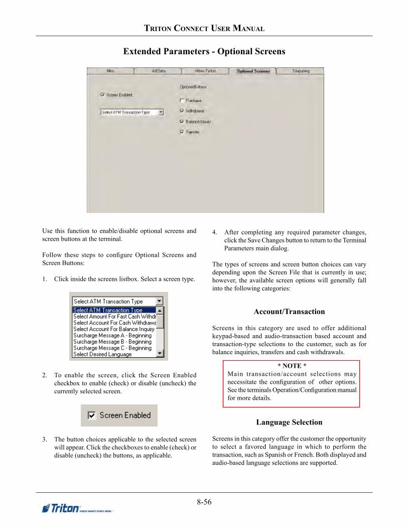
8-56
triton ConneCt User manUal
Extended Parameters - Optional Screens
* NOTE *Main transaction/account selections may necessitate the configuration of other options. See the terminals Operation/Configuration manual for more details.
Use this function to enable/disable optional screens and screen buttons at the terminal.
Follow these steps to configure Optional Screens and Screen Buttons:
1. Click inside the screens listbox. Select a screen type.
2. To enable the screen, click the Screen Enabled checkbox to enable (check) or disable (uncheck) the currently selected screen.
3. The button choices applicable to the selected screen will appear. Click the checkboxes to enable (check) or disable (uncheck) the buttons, as applicable.
4. After completing any required parameter changes, click the Save Changes button to return to the Terminal Parameters main dialog.
The types of screens and screen button choices can vary depending upon the Screen File that is currently in use; however, the available screen options will generally fall into the following categories:
Account/Transaction
Screens in this category are used to offer additional keypad-based and audio-transaction based account and transaction-type selections to the customer, such as for balance inquiries, transfers and cash withdrawals.
LanguageSelection
Screens in this category offer the customer the opportunity to select a favored language in which to perform the transaction, such as Spanish or French. Both displayed and audio-based language selections are supported.

8-57
Chapter 8 -terminal parameters
ExtendedPerimetersforPPPM-SecificSettings
NOTE: Consult the Propane Pump Payment Module (PPPM) Useres Manual for information on these settings.

8-58
triton ConneCt User manUal
Surcharge Message
Processor requirements may dictate that a particular type of wording be used in the surcharge notification message presented to customers. Screens in this category can offer a choice of surcharge message types, from which you can choose the most appropriate for your location. The location of the surcharge message in the transaction flow (Beginning or Ending) can also be selected.
Receipt Option
Screens in this category offer the customer the opportunity to choose whether to receive a printed receipt of their transaction, or not.
FastCashAmounts
Screen buttons in this category offer the customer the convenience of choosing from a number of predefined withdrawal amounts, rather than having to enter a value.
Purchase Selections
For applications in which a non-cash item can be purchased from the unit, such as phone cards or theater tickets, screen buttons can be chosen to provide the appropriate quantity/price options to the customer.
Select VAS Transaction
Screens in this category offer the customer the options to choose: (WAVES features)• Get Cash Now (normal cash transactions)• Money Transfers (Western Union)• Cash Check (CashWorks)• Prepaid Phone (PaySpot)
If any of these options is checked (enabled), the customer screen will offer these services. If enabled, you MUST configure that services particular options and ensure that the service is supported by a processor.

8-59
Chapter 8 -terminal parameters
Additional Device Information Support
Triton Connect supports retrieving and displaying an increased amount of information about the ATM, devices, and general configuration. Note: To use this functionality, the ATM software must also support this feature. For RL2000/FT5000/RT2000/RL5000 ATMs, software version 2.4 introduces support for this feature. If uncertain, please check with Triton Technical Support to verify if your ATM software version supports this functionality.
View Additional Device Information Support for viewing additional device information, such as more detailed card reader information, keypad information, or other information. To view this information, perform the following steps:
1. Open the Triton Connect Terminal Manager 2. Open the Terminal Data menu. 3. Select “Set Terminal Parameters”. 4. Navigate to the desired ATM and click the “View Parameters” button. 5. Select the “Version Numbers” tab. The right side of the Version Numbers tab contains the
additional information, if support.
Triton Connect Terminal Manager with Set Terminal Parameters menu option shown in the Terminal Data menu
6.0
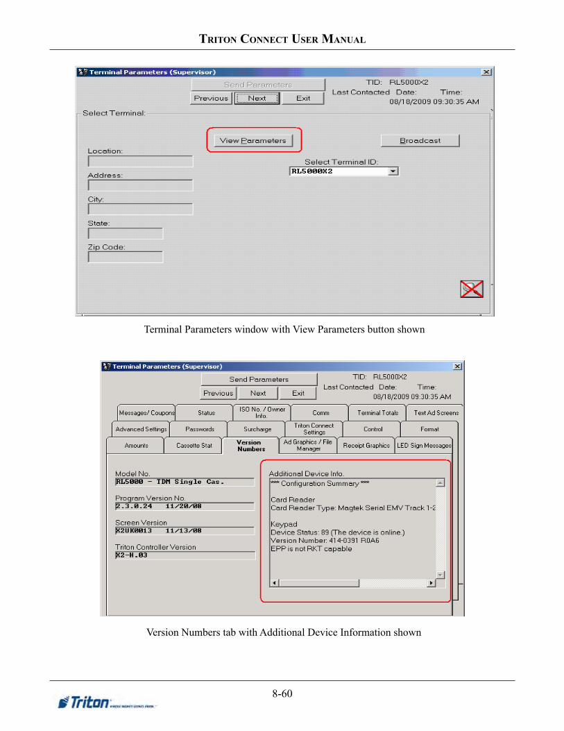
8-60
triton ConneCt User manUal
Terminal Parameters window with View Parameters button shown
Version Numbers tab with Additional Device Information shown

8-61
Chapter 8 -terminal parameters
Broadcast Store Messages
Broadcast Store Messages Triton Connect allows for the broadcasting of the Store Message. To use this feature, please perform the following steps:
1. Open the Triton Connect Terminal Manager 2. Open the Terminal Data menu. 3. Select “Set Terminal Parameters” 4. Click the “Broadcast” button. 5. Select the ATMs to broadcast to from the list on the right-side of the screen, using the add
button to add them to the broadcast list. 6. Once the broadcast list is complete, click the View Parameters button. 7. Select the “Messages/Coupons” tab. 8. Verify that the selected message is Store Message. 9. Enter the desired Store message.
Triton Connect Terminal Manager with Set Terminal Parameters menu option shown in the Terminal Data menu
6.0

8-62
triton ConneCt User manUal
Terminal Parameters window with Broadcast button shown
Terminal Parameters window, showing list of terminals available for broadcast

8-63
Chapter 8 -terminal parameters
Terminal Parameters window in process of configuring broadcast list
Terminal Parameters window in process of setting new Store Message for broadcasting

8-64
triton ConneCt User manUal
RKT Support Triton Connect had support for viewing if Remote Key Transfer (RKT) is enabled. If RKT is enabled, it may be disable using Triton Connect. However, to enable RKT will require a visit to the ATM.
View RKT Status Triton Connect allows viewing if RKT is enabled. To determine if RKT is enabled, perform the following steps:
1. Open Triton Connect Terminal Manager. 2. Open the Terminal Data menu. 3. Click “View Terminal Parameters”. This will present the Terminal Parameters screen. 4. Select the desired ATM and click “View Parameters”. 5. Navigate to the “Comm” tab. 6. If the “Remote Key Transfer” button appears, click it. This will present the Remote Key
Transfer screen. If the button does not appear, RKT is either not supported on the selected terminal or is disabled.
Triton Connect Terminal Manager with View Terminal Parameters menu option shown in the Terminal Data menu
6.0

8-65
Chapter 8 -terminal parameters
Terminal Parameters window with View Parameters button shown
Terminal Parameters window showing the “Remote Key Transfer” button for the selected terminal.
If this button does not appear, RKT is either not enabled or not supported on the ATM.

8-66
triton ConneCt User manUal
Remote Key Transfer window showing status as enabled
Change RKT Status Currently, Triton Connect allows only for the disabling of RKT. To enable RKT requires visiting the terminal. To disable RKT using Triton Connect, perform the following steps:
1. Open Triton Connect Terminal Manager. 2. Open the Terminal Data menu. 3. Click “Set Terminal Parameters”. This will present the Terminal Parameters screen. 4. Select the desired ATM and click “View Parameters”. 5. Navigate to the “Comm” tab. 6. If the “Remote Key Transfer” button appears, click it. This will present the Remote Key
Transfer screen. If the button does not appear, RKT is either not supported on the selected terminal or is disabled.
7. From the Remote Key Transfer screen, click “Disable RKT”.
Triton Connect Terminal Manager with View Terminal Parameters menu option shown in the Terminal Data menu
6.0

8-67
Chapter 8 -terminal parameters
Terminal Parameters window with View Parameters button shown
Terminal Parameters window showing the “Remote Key Transfer” button for the selected terminal.
If this button does not appear, RKT is either not enabled or not supported on the ATM.

8-68
triton ConneCt User manUal
Remote Key Transfer window showing status as enabled
Remote Key Transfer window after clicking the Disable RKT button
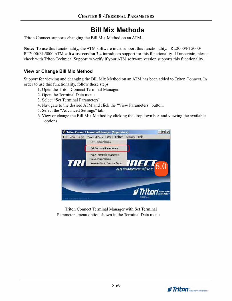
8-69
Chapter 8 -terminal parameters
View or Change Bill Mix Method
Bill Mix Methods Triton Connect supports changing the Bill Mix Method on an ATM.
Note: To use this functionality, the ATM software must support this functionality. RL2000/FT5000/RT2000/RL5000 ATM softwareversion2.4introduces support for this functionality. If uncertain, please check with Triton Technical Support to verify if your ATM software version supports this functionality.
Support for viewing and changing the Bill Mix Method on an ATM has been added to Triton Connect. In order to use this functionality, follow these steps:
1. Open the Triton Connect Terminal Manager. 2. Open the Terminal Data menu. 3. Select “Set Terminal Parameters”. 4. Navigate to the desired ATM and click the “View Parameters” button. 5. Select the “Advanced Settings” tab. 6. View or change the Bill Mix Method by clicking the dropdown box and viewing the available
options.
Triton Connect Terminal Manager with Set Terminal Parameters menu option shown in the Terminal Data menu
6.0

8-70
triton ConneCt User manUal
Terminal Parameters window with View Parameters button shown
Terminal Parameters window with Bill Mix Method selection shown

Chapter 9 - Journal Data

9-2
triton ConneCt user Manual
Introduction
In Chapter 5, Getting Terminal Parameters, we showed you how to retrieve terminal data. This data primarily consists of terminal parameter data and journal data. Once the data has been received and stored in the database, it can be accessed and viewed. In the previous chapter, Terminal Parameters, you saw how to access and view parameter data. In this chapter we show you how to view stored journal data and how to extract and archive selected journal information from the journal database
Accessing the Journal Data Function
Follow these steps to access the View Journal Data function:
1. Start the Terminal Manager application.
2. At the Terminal Parameters menu, select the View Journal Data option. The View Journal Data screen appears:
Viewing Journal DataFollow these steps to view journal data for the selected terminal:
1. Select the ID of the terminal you want to work with, using the Terminal ID drop-down list.
2. Click the View button. The journal data window appears, as shown here:
3. Bydefault,thefirstjournaldatarecordisdisplayed.To see the next journal entry, click the Next button:
Navigation
You can navigate through the journal data for the selected terminal by using the navigation buttons:
* NOTE *You can also use ALT-(key) combinations to quickly scroll through the journal entries. To do so, hold down the ALT key on the keyboard then press one of the following keys:
F - Moves to the First record.
P - Moves to the Previous record.
N - Moves to the Next record.
L - Moves to the Last record.

9-3
Chapter 9 -Journal Data
First
Movestothefirstjournaldatarecordinthedatabaseforthe selected terminal and displays the data.
Previous
Moves to the previous journal data record in the database for the selected terminal and displays the data.
Next
Moves to the next journal data record in the database for the selected terminal and displays the data.
Last
Moves to the last journal data record in the database for the selected terminal and displays the data.
Searching
Youcansearchthejournalrecordusingcriteriayoudefinewiththehelpofthesearchdefinitionfunction.Toactivateit, click the Search button:
Thesearchdefinitionwindowappears:
Youcanchoose the criteriayouwant touse todefineasearch by selecting it from the drop-down list:
Scroll through the list for more options. For each option the search window will automatically provide additional controlstohelprefinethecriteriayouselected.
Whenyou’vedefinedthesearchcriteriatoyourliking,clicktheApplybuttontoconductthesearch.Thefirstrecordthatmatches the search criteria will be displayed.
Printing Journal Data
You can print the journal, or selected portions of the journal, using the print function. To activate it, click the Print button:
The Print window appears:
Choose the print options you want and click OK to print the selected journal data to your default printer. A brief description of the print options is provided on the following pages.
Entry Range
Use the options in this area to choose the number of journal entries you want to print.
The Current Journal Entry option will print the information for the entry currently displayed in the View Journal main window.

9-4
triton ConneCt user Manual
The All Journal Entries option will print the information for ALL journal entries in the database. Note that the number of entries currently stored in the database is conveniently displayed in the option label (8 entries in this example). The number of entries in the database could be quite numerous, so exercise caution when choosing this option.
Report Format
Use the options in this area to control the format of the journal printout.
The Expanded option will print all information associated with each journal in an extended format that is more “user friendly” than the relatively more terse and abbreviated Comma Delimited and Journal Tape options.
The Comma Delimited report format is unavailable when printing to hardcopy; it is reserved for use with the Print to File option. When selected, the print function will send thereportoutputtoafile(whichyouspecify)insteadofto the printer.
The data associated with each entry are enclosed in quotes and separated by commas, as shown in this example:
This type of output is “application friendly,” storing journal data in a structured way that enables easy retrieval and formatting by spreadsheet, database or word processor programs.
The Journal Tape option produces a report that is formatted to appear as it would on the terminals’ receipt paper output, as in this example:
Other Print Options
The Print to File option is used to print Expanded, Comma Delimited and Journal Tape reports to disk instead of to the printer.
Select the Print Transactions Only option when you wish toexcludenon-transaction-specificentriesfromareport,such as terminal status, resets, etc. Note that this option is only available when the Print to File and Comma Delimited options are selected.
ABOUT THE PRINT RANGE
The default behavior of the print function is to select alljournalentriesinthespecifiedrangetobeprinted,even if they have been previously printed.
This behavior is controlled by the Print All Entries option. By default, this option is selected when you enter the print function.
If you wish to print only those entries in the print range that have not been previously printed, make sure the Print All Entries option is not selected.
COMMA DELIMITED REPORTS
It is recommended that the Comma Delimited option be used when compatibility with external applications such as spreadsheet and database programs is required. The comma-delimited format is designed to be easily imported into such applications.
NOTE: The Comma Delimited option is only enabled when the Print to File option is checked.

9-5
Chapter 9 -Journal Data
Response Code
TABLE 9-1 TRANSACTION RESPONSE CODES
RESPONSECODE DESCRIPTION RESPONSE
CODE DESCRIPTION RESPONSECODE DESCRIPTION
ACS 011 Cannot proceed transaction 0014 Invalid PIN
21 Transaction response 012 Amount too large 0015 Bank unavailable
41 Reversal response 013 Amount closed 0021 Unauthorized usage
51 Undefined Error 111 Reversal declined 0022 Expired card
61 Undefined Error COMMLINK 0024 Invalid PIN
97 Invalid sequence number 005 Transaction approved 0030 Ineligible transaction
99 PTDF read error 040 Ineligible account 0031 Ineligible account
TRITON STANDARD/EPS 050 Limit exceeded 0032 Cannot process
000 Transaction approved 051 Expired card 0041 Insufficient funds
001 Expired card 056 Ineligible transaction 0042 No further withdrawals
002 Unauthorized usage 076 Insufficient funds 0043 Try smaller amount
003 PIN error 100 Transaction declined 0044 Try smaller amount
004 Invalid PIN 101 Start of response and requestdo not match 0050 Invalid PIN
005 Bank unavailable 105 Ineligible card 0070 Ineligible card
006 Card not supported 201 Invalid PIN 0072 Closed account
007 Insufficient funds LYNK 0080 Ineligible account
008 Ineligible transaction 0000 Transaction approved 0082 Cannot process
009 Ineligible account 0011 Unauthorized usage
010 Number of daily withdrawalsexceeded 0012 Expired card
Any journal entries printed while the Mark Entries as Printed option is selected will be marked as “Previously Printed” in the database. For future printings, you may exclude these marked entries from a report by unchecking the Print All Entries option.
Select the Print All Entries option to include all entries in thespecifiedrangeintheprintout.Ifyouwishtoexcludeentries that have been marked as “Previously Printed,” do not select this option.
Transaction Response Codes
These codes are passed to the terminal by the transaction-processing organization, stored in the journal records and downloaded to Triton Connect upon command. The codes can appear in the JournalTextEntry field of theViewJournal window, as shown in this example:
The example above indicates a transaction was declined because of an INVALID PIN (Response Code 0050).
The definition of the code depends upon the particularprocessor organization handling the transaction. As you can see in the table, some code numbers appear multiple time (e.g. “005”), yet have different descriptions.
Archiving Journal Data
This function enables you to remove selected journal records from the database and save these journal records in aseparatedatabasefile.Thearchivedjournalrecordscanbeaccessed using the View Archived Journal Data function.
Follow these steps to archive journal data:
1. Start the Terminal Manager application.
2. From the File menu, select the Archive Journal Data option.
3. The Archive Journal Records screen appears:
4. The Database Date Format and Computer Date Format settings will not normally need to be changed. If a change in the settings is required, make those changes now.
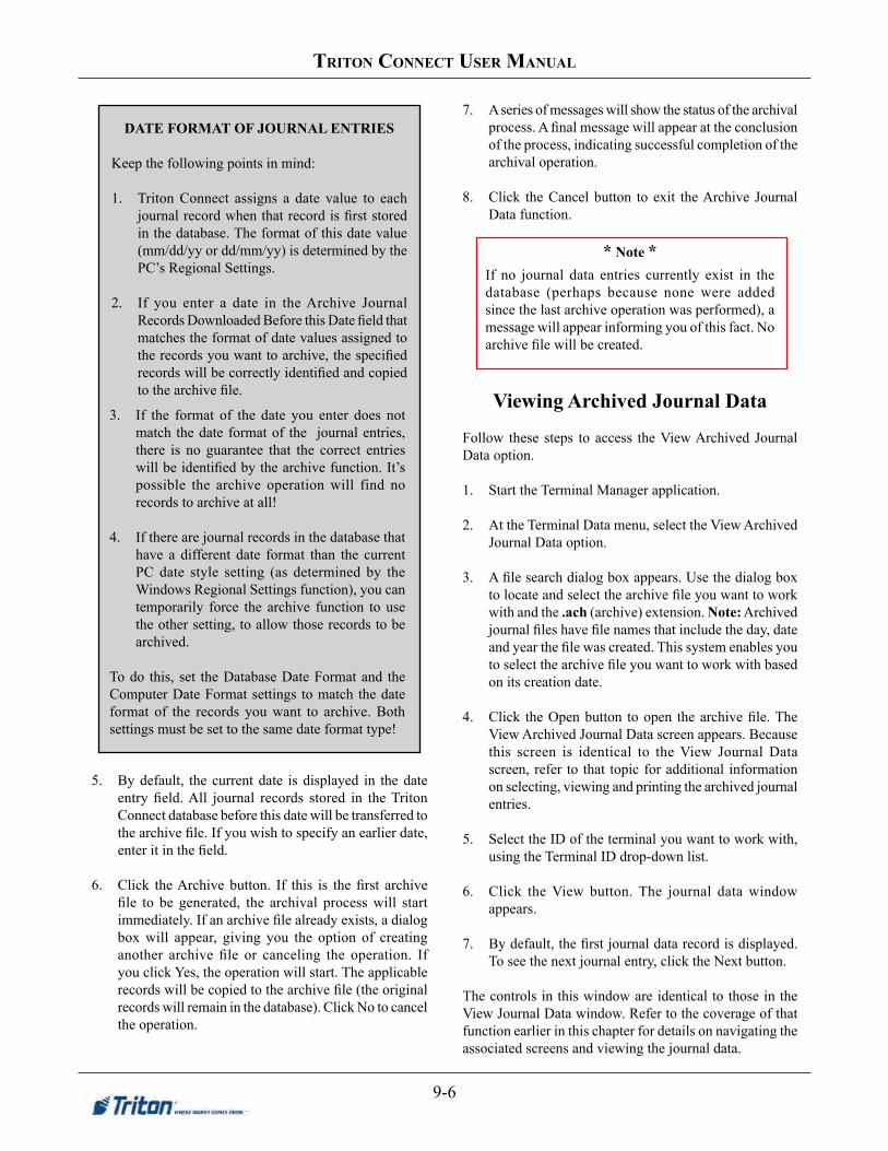
9-6
triton ConneCt user Manual
5. By default, the current date is displayed in the date entryfield.All journal records stored in theTritonConnect database before this date will be transferred to thearchivefile.Ifyouwishtospecifyanearlierdate,enteritinthefield.
6. Click theArchivebutton. If this is thefirst archivefile to be generated, the archival processwill startimmediately.Ifanarchivefilealreadyexists,adialogbox will appear, giving you the option of creating another archive file or canceling the operation. Ifyou click Yes, the operation will start. The applicable recordswillbecopiedtothearchivefile(theoriginalrecords will remain in the database). Click No to cancel the operation.
7. A series of messages will show the status of the archival process.Afinalmessagewillappearattheconclusionof the process, indicating successful completion of the archival operation.
8. Click the Cancel button to exit the Archive Journal Data function.
Viewing Archived Journal Data
Follow these steps to access the View Archived Journal Data option.
1. Start the Terminal Manager application.
2. At the Terminal Data menu, select the View Archived Journal Data option.
3. Afilesearchdialogboxappears.Usethedialogboxtolocateandselectthearchivefileyouwanttoworkwith and the .ach (archive) extension. Note: Archived journalfileshavefilenamesthatincludetheday,dateandyearthefilewascreated.Thissystemenablesyoutoselectthearchivefileyouwanttoworkwithbasedon its creation date.
4. Click theOpenbutton toopen thearchivefile.TheView Archived Journal Data screen appears. Because this screen is identical to the View Journal Data screen, refer to that topic for additional information on selecting, viewing and printing the archived journal entries.
5. Select the ID of the terminal you want to work with, using the Terminal ID drop-down list.
6. Click the View button. The journal data window appears.
7. Bydefault,thefirstjournaldatarecordisdisplayed.To see the next journal entry, click the Next button.
The controls in this window are identical to those in the View Journal Data window. Refer to the coverage of that function earlier in this chapter for details on navigating the associated screens and viewing the journal data.
DATE FORMAT OF JOURNAL ENTRIES
Keep the following points in mind:
1. Triton Connect assigns a date value to each journalrecordwhenthatrecordisfirststoredin the database. The format of this date value (mm/dd/yy or dd/mm/yy) is determined by the PC’s Regional Settings.
2. If you enter a date in the Archive Journal RecordsDownloadedBeforethisDatefieldthatmatches the format of date values assigned to therecordsyouwanttoarchive,thespecifiedrecordswillbecorrectlyidentifiedandcopiedtothearchivefile.
3. If the format of the date you enter does not match the date format of the journal entries, there is no guarantee that the correct entries willbeidentifiedbythearchivefunction.It’spossible the archive operation will find no records to archive at all!
4. If there are journal records in the database that have a different date format than the current PC date style setting (as determined by the Windows Regional Settings function), you can temporarily force the archive function to use the other setting, to allow those records to be archived.
To do this, set the Database Date Format and the Computer Date Format settings to match the date format of the records you want to archive. Both settings must be set to the same date format type!
* Note *If no journal data entries currently exist in the database (perhaps because none were added since the last archive operation was performed), a message will appear informing you of this fact. No archivefilewillbecreated.

9-7
Chapter 9 -Journal Data
Mask Journal Data PAN Data (new)
Added utility to mask PAN (Personal Account Numbers) data in journal records for Triton Connect databases and journal archivedfiles.Theserecordsshowthefirstsix(6)digitsandthelastfour(4)digitsoftheaccountnumbers.Themiddledigits are replaced with masking characters -- equal (=) signs. (Ex: 123456======7890)
Follow these steps to access the Mask Journal Data (PAN data) function:
1. Start the Terminal Manager application. 2. At the Terminal Parameters menu, select the File option. Select the Mask Journal Data option. The following screen
appears:
Log window. Lists actions of program
Will end programWill close/open Log window
Files selected for batch operation Log file Will process files in batch list
Will add to batch list below Will process current info
Used to select a file for processing
Displays location and name of current file selected

9-8
triton ConneCt user Manual
ALLOW ARCHIVING A CORRUPT DATABASE
The archive function has been updated to improve the handling of corrupt databases during a journal archive operation.
ACTIVATING JOURNAL ARCHIVE PROCESS
Follow these general steps to perform a journal archive operation:1. Select Archive Journal Data from the main menu under the File heading (see Figure 1-10)
2. Enter the target archive date, database date format, and computer date format when the archive journal recordsform appears (see Figure 1-11). Note that the target date refers to the date the records were downloaded
3. Press the .Archive. button.When you press the .Archive. button, the dialog will display the status of the archive operation at the bottom of the archive journal records form (see Figure 1-12).
PROCESSING RECORDS
Once the archive operation has been initiated, the application will cycle through the journal records, comparing each record date to the target archive date. If the record date is greater than or equal to the target date, the record is skipped. All other records will be stored in the archive database. Corrupt records will be skipped.
LOGGING ACTIVITY
TheTerminalManagerwilllogactivityinformationrelatedtothearchiveoperationtoafilenamed.Archivelog.log..Thefilewillbecreatedinthecurrentdirectory(typicallytheTritonConnectinstallationdirectory).
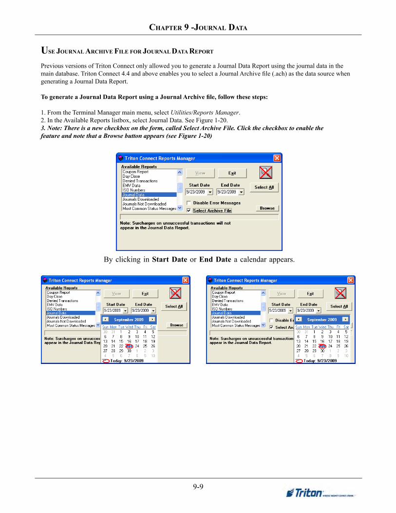
9-9
Chapter 9 -Journal Data
USE JOURNAL ARCHIVE FILE FOR JOURNAL DATA REPORT
Previous versions of Triton Connect only allowed you to generate a Journal Data Report using the journal data in the maindatabase.TritonConnect4.4andaboveenablesyoutoselectaJournalArchivefile(.ach)asthedatasourcewhengenerating a Journal Data Report.
To generate a Journal Data Report using a Journal Archive file, follow these steps:
1. From the Terminal Manager main menu, select Utilities/Reports Manager.2. In the Available Reports listbox, select Journal Data. See Figure 1-20.3. Note: There is a new checkbox on the form, called Select Archive File. Click the checkbox to enable thefeature and note that a Browse button appears (see Figure 1-20)
By clicking in Start Date or End Date a calendar appears.

9-10
triton ConneCt user Manual
4. Click the Browse button. A dialog appears, as shown in Figure 1-21. Use this dialog to locate and select an existingjournalarchivefile(fileswiththe..ach.extension).
5. Click Open onthebrowsedialogtoloadthefileandreturntothemaindialogwindow.AnentryfortheselectedjournalfilewillappearinthemainwindowasshowninFigure1-22.
6.ConfigurethedialogcontrolsasneededandclicktheView button to generate the report
DATA MANAGER WILL RESPECT DATABASE SIZE LIMITThe Triton Connect databases use the Microsoft Access database management system and thus have a 1 gigabyte limit.However, in previous versions of Triton Connect it was still possible to add data beyond the 1 gigabyte limit, and couldpotentially result in a corrupt database. To prevent this from occurring, the Data Manager in the Triton Connect 4.4 andabovehasbeenmodifiedsothatitwillnotaddanymorejournalsorparameterdataifthedatabaseisclosetothe1gigabyte limit.

Chapter 10 - LeD Sign MeSSageS

10-2
triton ConneCt USer ManUaL
Introduction
Triton Connect provides support for an optional feature of Triton Systems ATMs. This option is called the LED SIGN, and enables a terminal equipped with a special marquee-style light panel to display messages using a variety of attention-getting scrolling modes and animation effects.
In this chapter we will show you how to compose and manage these messages, using the LED Sign Messages function.
Accessing the LED Sign Messages Function
1. Start the Terminal Manager application.
2. From the Terminal Parameters menu, select the Set Terminal Parameters option. The Terminal Parameters screen appears:
3. Select the ID of the terminal you want to work with, using the Select Terminal ID drop-down list. If you want to download the same set of messages to more than one terminal, you can use the Broadcast feature to select multiple IDs.
4. Click the View Parameters button. The Select Terminal window is replaced with selection tabs for the various categories of terminal parameters, as shown:
5. Locate and click the LED Sign Messages tab with your mouse. The LED Sign Messages window appears, as shown here:
This is the LED Sign Messages main window. From here you can access all of the functions needed to create and manage your LED Sign messages. The next section provides an overview of these functions.
Overview of the LED Sign Messages Function
This section will provide a general overview of the functions of the LED Sign Messages window. Using the functions available to you in this window you can: • Createnewmessages.
• Saveyournewlycreatedmessages.

10-3
Chapter 10 -LeD Sign MeSSageS
• SendthemessagesyoucreatetotheLEDSignonyour Triton Systems ATM.
• Openmessages that you’ve created and savedpreviously.
• Change the text and/or special display effectsassociated with a message.
• Review themessages that are currently beingdisplayed by the LED Sign.
Let’sbrieflylookatthevariouscomponentsoftheLEDSign Messages window. These features will be covered more fully in the remaining sections of this chapter.
We can organize the various controls into these areas:
Message Definition Window
The information associated with the message you are currentlyworkingonwillappearintheMessageDefinitionWindow. This information will consist of various display formatting commands and the text of the message itself. Here is an example message:
Thefirsttwoentriesareformattingcommands,whichtellthe LED Sign to place the message in the Top line of the display, using the Automode display effect to present the message “Have A Nice Day!”
Command Buttons
These buttons provide quick access to the functions you need to open, save, select and view messages:
New. Clicking this command button clears the current message definition display and prepares thewindow todisplay a new message.
Open. Clicking this command button brings up the Opendialogbox,whichenablesyoutolocateandopenapreviouslysavedmessagefile.Themessage,onceopened,willdisplayintheMessageDefinitionwindow.
Save. Clicking this command button brings up the Save dialog box, which enables you to name and save a newly created message.
Message Definition Window
Comand Buttons
Display Controls

10-4
triton ConneCt USer ManUaL
View Current Sign Data. Clicking this command button will display the Current Sign Data window, which shows the content of the messages that are currently being presented by the LED Sign.
Select Messages. Clicking this command button brings up the Message Selection window, which displays a list of all saved messages. You can choose one or more messages from a list of available messages to be placed in the Selected Messages list.
The messages you select will be sent to the LED Sign on a selected terminal when the Send Parameters button is clicked.
Display Controls
There are three drop-down style list boxes in the Controls area of the LED Sign Messages window:
Position. The LED Sign is a two-line display, and can presentyourmessageinthetopline,bottomline,orfillbothdisplay lines, depending upon the selection you make here.
Mode. This list allows you to choose from the standard display modes. The options represent special display effects withnameslikeAutomode,Hold,FlashandRoll-Up.
Special. This list box contains optional display modes you can use instead of the standard modes. The options include additional display effects like Twinkle, Sparkle and Snow, as well as pre-formatted messages that are ready to use,suchas“NoSmoking,”“Don’tDrinkandDrive”and“Thank You.”
Creating a Message
AnLEDSigncontainseightkilobytes(KB)ofRAM,whichitusestostoreupto21messagesyou’vecomposedand sent to it. Each of these messages can have up to 150 individual characters (not including formatting commands) in the actual message text. You can include more than one line of message text in a single message definition file, as long as you don’t exceed the 150character limit.
The following procedure will show you how to create a message. The procedure begins at the LED Sign Messageswindow, somake sure it’sdisplayedbeforebeginning (if you’re unsure how to display theLEDSign Messages window, refer to the section, Accessing the LED Sign Messages Function, earlier in the chapter). To create a new message, perform the following steps:
STEP1:SELECTPOSITION.
STEP2:SELECTMODEORSPECIAL.
STEP 3: TYPE THE MESSAGE TEXT.
STEP 4: SAVE THE MESSAGE.
STEP 1: Select Position
Click on the Position list box in the Controls area. The following list of display position options is presented:
ChoosejustONEpositionforyourmessagefromthelist.The meaning of each option is as follows:
Fill. If the message text is longer than the LED Sign can display on a single line, the LED Sign will attempt tofill both lines of its two-line display.The textwillappear centered on each display line. If necessary, any additional text will be scrolled onto the display lines after a short pause, until the full text of the message has been displayed. If the text is less than a full line, it will appear on the top line.

10-5
Chapter 10 -LeD Sign MeSSageS
TABLE 10-1STANDARD DISPLAY MODES
No. MODE DESCRIPTION
1 AUTOMODE Various display modes from this listwill be chosen randomly.
2 HOLD The message remains stationary.
3 FLASH The message remains stationary, butflashes.
4 ROLL UP The previous message is pushed upby the new message.
5 ROLL DOWN The previous message is pusheddown by the new message.
6 ROLL LEFT The previous message is pushed leftby the new message.
7 ROLL RIGHT The previous message is pushed rightby the new message.
8 WIPE UPThe previous message is wiped overby the new message, from bottom totop.
9 WIPE DOWNThe previous message is wiped overby the new message, from top tobottom.
10 WIPE LEFT The previous message is wiped overby the new message, from right to left.
11 WIPE RIGHT The previous message is wiped overby the new message, from left to right.
12 ROTATE The message travels from right to left.
13 ROLL INThe previous message is pushedtoward the center of the display by thenew message.
14 ROLL OUTThe previous message is pushedoutward from the center of the displayby the new message.
15 WIPE INThe previous message is wiped overby the new message using an inwardmotion.
16 WIPE OUTThe previous message is wiped overby the new message using an outwardmotion.
17 SCROLLThe new message will push thebottom line of the previous messageup into the top line of the display.
Top. The text will be displayed on the top line of the two-line LED Sign display. If the text is longer than the LED Sign can display at one time, after a short pause additional text will be scrolled onto the display, replacing the previous text until the full text of the message has been displayed. Bottom. The text will be displayed on the bottom line of the two-line LED Sign display. If the text is longer than the LED Sign can display at one time, after a short pause additional text will be scrolled onto the display, replacing the previous text until the full text of the message has been displayed.
STEP 2: Select Display Mode (Standard or Special)
Standard Display Modes. Click on the Mode list box. The following list is presented (scroll the list box window to view and select from the available options):
The list represents all of the standard display modes you canapplytoyourmessage.ChoosejustONEmodefromthe list to apply to your message, by clicking on it with the mouse. The selected formatting mode command will appearintheMessageDefinitionwindow.Thefollowingtable lists all of the standard modes and describes their associated display effects.
** IMPORTANT **If you neglect to choose a formatting mode, the LED SignwilldisplayyourmessageusingAUTOMODEby default!

10-6
triton ConneCt USer ManUaL
Special Display Modes. Instead of a standard display mode, you can choose a display mode for your message from the Special list. Click on the Special list box. The following list is presented (scroll the list box window to view and select from the available options):
Thefirsteightoptionsinthelistaredisplayeffectsthatcanbe applied to your message text. The last remaining eight items are preformatted messages or special animated themes that can be displayed in addition to any other messages that may be displayed.
The following table lists all of the special modes and describes their associated display effects.
STEP 3: Type Message Text
Type a message of your own directly into the Message Definitionwindow.Rememberthe150characterlimitofeachmessage(thiscountDOESNOTincludetheformatcharacters).
Yourmessagedefinitioncanactuallyholdmorethanonelineof text. Repeat steps1 through3 to compose theseadditional lines.Remember that the entiremessage canhold a maximum of 150 characters! Here is an example of a messagedefinitionthatactuallyconsistsoftwolinesoftext:
TABLE 10-2LED SIGN SPECIAL DISPLAY MODES
No. MODE DESCRIPTION
These modes are display effects that can be applied toyour messages.
1 TWINKLE The message will twinkle on thedisplay.
2 SPARKLEThe new message will sparkleover the current message,replacing it.
3 SNOW The message will "snow" onto thedisplay.
4 INTERLOCK
The new message will interlockover the previous message inalternating rows of dots, from eachend.
5 SWITCH
Alternating characters of thecurrent message will switch off thedisplay in an up and down manner.The new message will switch on ina similar manner.
6 SLIDEThe new message slides onto thedisplay one character at a time,from right to left.
7 SPRAYThe new message sprays acrossand onto the display, from right toleft.
8 STARBURST Starbursts will explode yourmessage onto the display.
TABLE 10-2LED SIGN SPECIAL DISPLAY MODES
No. MODE DESCRIPTION
These modes are preformatted messages or animatedthemes. They are not applied to your messages.
9 SCRIPT"WELCOME"
The word "Welcome" is written inscript across the display.
10 SLOT MACHINESlot machine symbols appear inan animated sequence on thedisplay.
11 NO SMOKING
A cigarette image appears, and isthen extinguished, to be replacedwith the universal no smokingsymbol.
12 DON'T DRINKAND DRIVE
A car runs into a cocktail glassand is replaced with the message,"Please Don't Drink and Drive."
13 FIREWORKS Fireworks explode randomly onthe display.
14 TURBO CAR A car drives across the display.
15 CHERRY BOMB A bomb fuse burns down, followedby an explosion.
16 SCRIPT "THANKYOU"
The words "Thank You" are writtenin script across the display.

10-7
Chapter 10 -LeD Sign MeSSageS
STEP 4: Save the Message
Use the Save function to give your message a name and saveittoyourPC’sharddrive.Refertothenextsection,Saving a Message, for step-by-step procedures.
Saving a Message
Onceyou’vecreatedamessage,itmustbegivenanameandsavedasadatafilebeforeitcanbesenttotheLEDSign. The LED Sign Messages window contains a feature that enables you to do this.
The procedure begins at the LED Sign Messages window, somake sure it’s displayedbefore beginning (if you’reunsure how to display the LED Sign Messages window, refer to the section, Accessing the LED Sign Messages Function, earlier in the chapter).
Theproceduresassumethatyouhavecreatedormodifiedamessage file, and nowwish to save it on your PC’shard drive. The message contents (display formatting commands and message text) should be visible in the LED Sign Messages window. To save the message, perform the following steps:
STEP1:CLICKTHE“SAVE”BUTTON.
STEP2:CHOOSEANAMEFORTHEMESSAGEFILE.
STEP3:CLICKTHE“OK”BUTTON.
STEP 1: Click the Save Button
The Save dialog box will be displayed:
STEP 2: Choose a Name for the Message
When you are performing this step remember that the Save dialogboxwillonlyacceptfilenameswithamaximumlength of eight characters (not including the “.LED” extension).Forexample,thefilenames“Welcome!”“Bye!”and“Yummy!”arevalidfilenames,while“SpendMoney,”“GoodFood!” and “See You Soon!” are not.
Hereisanexampleofatypicalmessagedefinition,whichincludes formatting commands and message text:
Andhereisanexampleofamessagefilenameentrythatcould be made for this message in the Save dialog box:
STEP 3: Click the Save Button
Whenyouaresatisfiedwiththenameyou’vechosenforthe message, simply click the SAVE command button. The filewillbesavedandyouwillbereturnedtotheLEDSignMessages main window.
FILE LOCATIONSA point to remember concerns the location of yourmessagefiles.Bydefault, the save functionplaces yourmessagefiles in a sub-folder namedLED, located in the Triton Connect program folder (TRITCONN)onyourharddrive.
** IMPORTANT **ThemessagefilesmustremainintheLEDfolderinorder to be accessible to Triton Connect!

10-8
triton ConneCt USer ManUaL
Opening a Message
Themessagefilesyou’vecreatedandsavedmayneedtoberevisedatsomepointinthefuture.Todothisyou’llneedtoopenthepreviouslysavedfile,makeyourchanges,thensave themodifiedfile once again. In this sectionof theAddendum you will learn how to open a previously saved messagefile.Forproceduresonmakingchangestoafileafteryou’veopenedit,seeSection6,ChangingMessages.
The procedures begin at the LED Sign Messages window, somakesure it’sdisplayedbeforebeginning.Toopenamessage, perform the following steps:
STEP1:CLICKTHE“OPEN”BUTTON.
STEP 2: SELECT THE MESSAGE FILE.
STEP3:CLICKTHE“OK”BUTTON.
STEP 1: Click the Open Button
TheOpendialogboxwillappear:
For this example we will select and open the “Junkfood” messagefile.Thefilesshownarefordiscussionpurposesonly and do not exist on your system!
STEP 2: Select a Message File
Clickonthe“Junkfood”messagefilenametoselectit.
STEP 3: Click the Open Button
You will be returned to the LED Sign Messages main window.TheMessageDefinitionwindownowshowsthecontentsofthefile:
Modifying a Message
This Section will show you how to make changes to the contentofamessageyou’vejustcreated,oroneyou’vepreviously created and saved. The procedures begin at the LEDSignMessageswindow,somakesureit’sdisplayedbefore beginning. To change a message, perform the following steps:
STEP1:OPENAMESSAGEFILE.
STEP2:CHANGEPOSITION.
STEP3:CHANGEMODEORSPECIAL.
STEP 4: CHANGE MESSAGE TEXT.
STEP 5: SAVE THE MESSAGE.
You may not need to perform all of the above steps in all cases; select only the procedures that apply to the changes you need to make!
STEP 1: Open a Message File
Follow the step-by-step instructions in Section 5 to openamessagefile. Ifyou’ve justcreated themessage,the contents should already be displayed in the Message Definitionwindow.
Oncethedisplayformattingmodesandtextoftheselectedmessage file are displayed in the Message Definition window, you can begin making changes. The following steps should be used to change the applicable part of the message, as necessary.

10-9
Chapter 10 -LeD Sign MeSSageS
STEP 2: Change Position ClickthemousecursorintheMessageDefinitionwindow,anywhere on the same line as the current position command. Aflashingtextcursorshouldbevisibleatthislocation.Press the DELETE key on the keyboard. The position command will be erased. Now choose a new position command from the Position list in the Controls area. The new position code will be inserted.
STEP 3: Change Display Mode
ClickthemousecursorintheMessageDefinitionwindow,anywhere on the same line as the current mode command. A flashing text cursor should be visible at this location. Press the DELETE key on the keyboard. The mode command will be erased. Now choose a new mode the Mode list in the Controls area. The new mode command will be inserted.
STEP 4: Change Message Text
Some or all of the text portion of a message can be erased a character at a time using the DELETE and BACKSPACE keys on your PC keyboard. Alternatively, you can use the mouse to select the text to delete using a “Click and Drag” approach to highlight some or all of the text before pressing the DELETE or BACKSPACE keys.Click the mouse in the text to select a starting point and type your text into the message.
STEP 5: Save the Message
Click the SAVE button to bring up the Save dialog box. Typeanameforyourmessageinthefilenameentryboxand click the SAVE button the save the message.
If you have made changes to the contents of a previously savedfile,butwishtosavethe changes using a newmessage name, you may do so by simply typing a new name for the message. This will save the message with the new name,leavingtheoriginalfileintact.See the section, Saving a Message, for additional information on these procedures.
Sending a Message The following procedure will show you how to select the messages you want to send to the LED Sign. Before beginning, make sure the LED Sign Messages window is displayed.
The following procedures assume that one or more terminals have been previously selected for individual or broadcast contact.
To send your message(s) to the LED Sign, perform the following steps:
STEP 1: CLICK THE “SELECT MESSAGES” BUTTON.
STEP 2: HIGHLIGHT A MESSAGE FILE NAME.
STEP3:CLICKTHE“ADD”BUTTON.
STEP 4: CLICKTHE “SEND PARAMETERS”BUTTON.
STEP 1: Click the Select Messages Button The Message Selection window will be displayed:
* NOTE *If no standard mode is selected, the LED Sign will default to Automode.
* NOTE *The Call Monitor application must be running (with one or more active Call Processors) in order to send messages to the selected terminal(s).

10-10
triton ConneCt USer ManUaL
STEP 2: Highlight a Message File Name
Click on a message in the Available Messages list to highlight it. To highlight a group of messages, click once on a message name, then hold down the SHIFT key while clicking on another message name. This will highlight not only these two messages but any other messages between them.
To highlight messages that do not fall neatly into a row, hold downtheCTRLkeywhileyouclickonindividualmessagenames anywhere in the list to highlight them. You can use the same technique to highlight messages in the Selected Messages list.
STEP 3: Click the Add Button
The selected messages are added to the Selected Messages list (and will be highlighted in red):
OnlymessagesthatarehighlightedinREDintheSelectedMessages window can be sent to the LED Sign. To resend a message that has already been sent, delete the message from the Selected Messages list, then add it again.
ToremoveamessagefromtheSelectedMessageslist,firstclick on the message name:
Then click the DELETE button to remove it.
Select any other messages you wish to send to the LED Sign atthistime.Rememberthe21-messagelimit!
STEP 4: CLICK THE “SEND PARAMETERS” BUTTON.
A Call Scheduler window will open:
PressENTERor click onOK to schedule the selectedmessage(s) to be sent to the selected terminal immediately. Or,entertheappropriatedatatoschedulethecontactforlater. The Terminal Parameters window will be closed and the Call Processor application will send the message(s) to the LED Sign-equipped terminal at the scheduled time.
For additional information on selecting and scheduling terminals, see the chapter on Terminal Parameters.
Reviewing Messages
The following procedures will show you how to obtain a quick look at the messages that are currently being displayed byaselectedterminal’sLEDSign.Theproceduresbeginat theLEDSignMessageswindow, somake sure it’sdisplayed before beginning. Perform the following steps:
STEP1: CLICKTHE“VIEWCURRENTSIGNDATA”BUTTON.
STEP2: CLICKTHE“BACK”BUTTON.

10-11
Chapter 10 -LeD Sign MeSSageS
STEP 1: Click the View Current Sign Data Button
The Current Sign Data window will open, as shown here:
Thesigndatawillconsistofamessagefilenamefollowedby the content of the message. If necessary, scroll through the list to view multiple messages. This information represents feedback from the LED Sign, obtained during TritonConnect’smost recent contactwith the selectedterminal.
EXAMPLE DATA ONLY!The Sign Data shown is provided for discussion purposes only and does not exist on your system!
STEP 2: Click the Back Button
Whenyou’vefinishedreviewingthemessages,clickthiscommand button to return to the LED Sign Messages main window.

thiS page intentionaLLy Left BLank
10-12
triton ConneCt USer ManUaL

Chapter 11 - reports Manager

11-2
triton ConneCt User ManUal
Introduction
Triton Connect enables you to produce detailed reports. These reports are based on the parameter, journal, and close data obtained from your terminals.
In this chapter, we’ll show you how to access and view reports.
Accessing the Reports Manager
1. Start the Terminal Manager application.
2. From the Utilities menu, select the Reports Manager option. The Reports Manager main window appears:
Viewing ReportsThe Available Reports list offers a number of report types. Follow these steps to view a report:
1. Select the type of report from the Available Reports list. The following report types are available:
2. When some reports are selected additional controls will appear in the Reports Manager. These controls are used to refine the report criteria. They are described in the next section, Changing Report Criteria.
3. Make any needed control selections to further define the output of the selected report type. Click the View button to generate the report.
Changing Report Criteria
The Reports manager will offer additional controls for some report types. These controls allow you to select criteria to further refine the output of the report.
Close-Type Reports
Close reports require additional controls to allow selection of the type of close data to be viewed (trial close or final close) and range of records to view in the report. These report types are: Cassette Close and Day Close.
When either of these two close report types is selected, additional control options appear on the Reports Manager main window, as shown here:
DISABLING ERROR MESSAGES
If errors exist in the data being used to generate the report (such as incorrect or corrupted terminal data in the database) a series of error messages will be presented. Each error message must be dismissed before the report can be viewed.
If a large number of terminals are included in the report criteria it is possible that the number of error messages could be excessive. In such cases you may wish to place a check mark in the Disable Error Messages checkbox before clicking the View button. This will temporarily disable the display of error messages for ALL reports.
To view error message again simply remove the check mark before viewing the next report.
Call Failures Journal Downloaded *
Call List Report * Journal Not Downloaded *
Cassette Status Most Common StatusMessages
Check Digits * Schedule Close Status *
Check Digits Triple DES * Terminal Configuration
Coupon Report Terminal Down Time
Day Close Terminal Status
Denied Transactions Terminal Status Messages
ISO Numbers Terminal Totals
Journal Data Version Numbers
* New Reports
Call Failures Journals DownloadedCall List Report Journals Not DownloadedCassette Close Most Common Status
MessagesCassette Status Scheduled Close StatusCheck Digits Terminal ConfigurationCheck Digits 3Des Terminal Down TimeCoupon Report Terminal FilesDay Close Terminal StatusDenied Transactions Terminal Status MessagesEMV Data Terminal TotalsIso Numbers Triton Connect NumbersJournal Data Version Numbers

11-3
Chapter 11 - reports Manager
USING FILTERS WITH REPORTSBy default, the reports generated by the Reports manager are based on data obtained from all terminals in the terminal database.However, although a good deal of customization of the report content is possible using the available controls for each report type, most of these controls do not allow you to produce reports for specific terminals.To tune your reports to specific terminals, establish a filter using the Filters function of the Terminal Manager. Ensure the filter is enabled before choosing and viewing a report. The Reports Manager will display the selected report using only the data from the terminals that fit the filter criteria.
Close. Choose this option to generate a report based on final close data.
Trial Close. Choose this option to generate a report based on trial close data.
Most Recent Record. This option will generate a report based on the most recent close data for each terminal.
All Records. This option will generate a report based on all available close data for each terminal.
Calendar-Style Date Range Selection
The Journal Data, Journals Downloaded, Journals Not Downloaded, Most Common Status Messages, Terminal Down Time, and Terminal Status Messages reports provide a calendar-based date-range selector, as shown here:
Note that the Start Date and End Date buttons also become active when the Journal Data report type is selected.
By default, the starting and ending dates for the report are automatically set to the current day, which selects for the most recent one-day range of journal activity.
To specify a different starting date, select a month and year using the drop-down lists. When the calendar changes to reflect the chosen month/year, click the day of the month: the day “button” will depress. Then click the Start Date button to select this day/month/year as the new starting date.
Specify a second date (either the same as the starting date, or later, as applicable) and click the End Date button to lock it in.
If you wish to see journal data for all dates available in the database, click the Select All command button.
Terminal Status
The Terminal Status report requires additional controls to further refine the data returned by the Reports Manager.
When the Terminal Status report type is selected, the window changes to provide additional Report Details controls, as shown here:
All Terminals. Selecting this option will generate a Terminal Status report using all terminals in the database.
Any Terminal Error. Selecting this option will generate a Terminal Status report using only those terminals currently experiencing some sort of error condition.
Terminals Reporting Low Cash. Selecting this option will generate a Terminal Status report using only those terminals currently reporting a low cash condition.
Specific Terminal Error #. If you want to generate a status report for terminals that are experiencing a specific type of error, select this option and enter the error number. See Chapter 6 for a table of error conditions and associated error code numbers.

11-4
triton ConneCt User ManUal
Report Viewer
After the report is generated, it will appear in a window as illustrated. The controls are described below, from left to right.
Printer Button
The Printer button prints the report to the default printer used by the PC.
Envelope Button
The Envelope button allows the report on screen to be exported into another format or application.
The Lightening Bolt button refreshes the data on screen with the latest information available from the databases.
Percentage of View
The Percentage of View drop-down changes the size of the page viewed in the report window.
The last button is the Search Control, which will bring up the following box:
Type in the text or values you wish to search for, and select Find Next to Search or Cancel to exit the Search mode.
Lightening Button
The Tree button toggles from Preview to Report Only and back again. The Preview is available for every report that requires more than one line of entry for any terminal. Selecting the Terminal ID from the Preview section takes you immediately to the data in the report regarding that terminal.
Tree Button
Search Button
Navigation Control
The next set of controls are the Navigation controls, allowing you to move quickly from one page to the next, forward and backward. You may also type in the page number you wish to go directly too.

11-5
Chapter 11 - reports Manager
Call List Report
The Call List Report provides information on the currently scheduled and persistently scheduled calls in the active Call List. The Call List Report also provides a list of commands to be performed during the call, the next scheduled time to call, and whether or not that attempt has been made.
Commands
The Call Failures report provides a listing of all those terminals that Triton Connect was unable to reach after five attempts from the scheduled Call List.
Terminal ID -The name used to identify the terminal when it was initially configured. Time to Call - The last scheduled call date and time for which an attempt was made to contact the terminal.
Call Interval - The interval that was established when the terminal was scheduled for contact. See Chapter 6, Getting Terminal Data, for additional information on call scheduling and interpreting the Call Interval setting.
Retry Count - The Retry Count indicates the number of attempts made by Triton Connect to contact the indicated terminal. Triton Connect will make five attempts to reach a terminal before reporting a call failure. Such failures will be visible in this report.
The Call Error list feature of Triton Connect will indicate terminals which were not reached on the first or subsequent attempts. See Chapter 6, Status monitoring, for more information.
Total Failed Calls - The total number of failed call entries in the report.
Call Failures Report
Call Summary(Case Sensitive)
J Journal Data
a All Journal Data
x X-entries Journal Data
P Parameters
p Selected Parameters
T Synchronize Date/Time
E Error Status
B Coupon Data

11-6
triton ConneCt User ManUal
for a number of reasons, such as poor note quality, currency not loaded correctly in the cassette, machine error, etc.
Quantity - Number of bills in the cassette applicable to the Start, Dispensed and Remaining headings.
Amount - Total value of the currency in the cassette applicable to the Start, Dispensed and Remaining headings.
Start - Under the Quantity heading, this is the number of bills in the cassette after the completion of the last Cassette Close operation. Typically, after a cassette close is performed the cassette is restocked with cash and the terminal’s Starting Quantity parameter is reset to reflect the total number of bills in the cassette when it is placed back in service.Under the Amount heading, this is the total value of the currency in the cassette after the completion of the last Cassette Close operation. Since the cassette is usually restocked with cash after the close, this value will normally represent the total value of cash in a full cassette.
Dispensed - Under the Quantity heading, number of notes dispensed (including rejected notes) since the last Cassette Close. Under the Amount heading, the total value of the cash that was dispensed (including rejects) since the last Cassette Close.
Remaining - Under the Quantity heading, number of notes remaining in the cassette when the close operation took place. Under the Amount heading, the total value of the cash remaining in the cassette when the close operation took place.
Cassette Close Report
The Cassette Close Report provides information summarizing the most current financial transactions (involving an indicated cassette) performed by the indicated terminal. Typically, this summary covers the period of time since the last Cassette Close operation was performed on the terminal.
Terminal ID - The name used to identify the terminal when it was initially configured. Date - Date on which the Cassette Close operation was performed.
Contact Time - Time at which the close information was downloaded from the terminal.
Cassette ID - Identification for the cassette(s) installed in the ATM. For single-cassette ATMs, the ID is simply ‘Single’. For multi-cassette ATMs, the ID will be an alpha code designation in the series ‘A’, ‘B’, ‘C’, or ‘D’, depending upon how many cassettes are installed in the unit.
Bill Size - This is the denomination of the currency loaded in the designated cassette.
Transactions - This is the total number of withdrawal transactions involving the designated cassette since the last Cassette Close operation was performed.
Reject Events - This is the number of times currency designated for dispense to the customer was routed to the reject cassette or vault in the terminal. Rejects can occur

11-7
Chapter 11 - reports Manager
Cassette Status Report
The Cassette Status Report provides information on the cassette as of last contact with the terminal.
Terminal ID - The name used to identify the terminal when it was initially configured. Terminal Location - This is the terminal location descriptionwhen the terminal was initially entered into the Triton Connect database. This is usually the name of the store or other location where the terminal is installed.
Cassette ID - Identification for the cassette(s) installed in the ATM.
Bill Size - This is the denomination of the currency loaded in the designated cassette.
Reject Events - This is the number of times currency designated for dispense to the customer was routed to the reject cassette or vault in the terminal.
Cash Loaded - Amount of cash loaded in the cassette when it was restocked.
FOR MORE DETAILThe Cassette Status parameters described here summarize descriptions provided in additional detail in the previous section, which covered the Cassette Close Report. See that section for more information on the following parameters:
1. Terminal ID
2. Cassette ID
3. Reject Events
4. Cash Loaded (See description of the Start parameter)
5. Cash Dispensed (See description of the Dispensed parameter)
6. Cash Remaining (see description of the Remaining parameter)
Cash Dispensed - Amount of cash dispensed since the last cassette close.
Cash Remaining - Cash remaining in the cassette.
Totals - Totals for all cassettes in the indicated terminal.

11-8
triton ConneCt User ManUal
Check Digits Check Digits Triple DES
Terminal ID - The name used to identify the terminal when it was initially configured.
Master Check Digits - The string verifying the PIN Master keys when entered in the terminal.
Comm Check Digits - The string verifying the PIN Working keys when downloaded from the Host processor.
Last Contacted - The date and time at which the terminal was last contacted.
The Check Digits Triple DES displays a management report that shows the check digits strings associated with the currently loaded Master nad Working keys for Triple DES encryption.
Terminal ID - The name used to identify the terminal when it was initially configured.
PIN Master Key Left/Right - The strings verifying the PIN Master keys when entered in the terminal.
MAC Master Key Left/Right - The strings verifying the MAC Master keys (if used) when entered in the terminal.
PIN Working Key Left/Right - The strings verifying the PIN Working keys when downloaded from the Host processor.
MAC Working Key - The strings verifying the MAC Working keys (if used) when downloaded from the Host processor.
Last Contacted - The date and time at which the terminal was last contacted.
The Check Digits Report displays a management report that shows the check digits string associated with the currently loaded Master and Working keys.

11-9
Chapter 11 - reports Manager
The Coupon Report provides information summarizing the types and numbers of coupons that have been printed by the indicated terminal. Typically, this summary covers the period of time since the terminal was placed in operation.
Terminal ID - The name used to identify the terminal when it was initially configured. .TCC File - Name and location of the coupon file associated with the coupon graphic files listed under the Coupon heading.
Total Coupons Printed - Total number of coupons printed since the terminal was placed in operation.
Coupon - File name of a Receipt Graphic file.
Number Printed - Total number of a particular Receipt Graphic that have been printed since the terminal was placed in operation.
Coupon Report
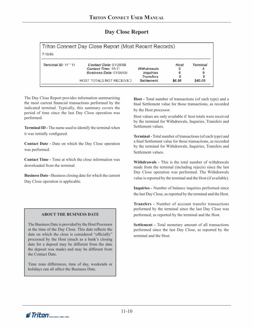
11-10
triton ConneCt User ManUal
Host - Total number of transactions (of each type) and a final Settlement value for those transactions, as recorded by the Host processor. Host values are only available if host totals were received by the terminal for Withdrawals, Inquiries, Transfers and Settlement values.
Terminal - Total number of transactions (of each type) and a final Settlement value for those transactions, as recorded by the terminal for Withdrawals, Inquiries, Transfers and Settlement values.
Withdrawals - This is the total number of withdrawals made from the terminal (including rejects) since the last Day Close operation was performed. The Withdrawals value is reported by the terminal and the Host (if available).
Inquiries - Number of balance inquiries performed since the last Day Close, as reported by the terminal and the Host.
Transfers - Number of account transfer transactions performed by the terminal since the last Day Close was performed, as reported by the terminal and the Host.
Settlement - Total monetary amount of all transactions performed since the last Day Close, as reported by the terminal and the Host.
Day Close Report
ABOUT THE BUSINESS DATE
The Business Date is provided by the Host Processor at the time of the Day Close. This date reflects the date on which the close is considered “officially” processed by the Host (much as a bank’s closing date for a deposit may be different from the date the deposit was made) and may be different from the Contact Date.
Time zone differences, time of day, weekends or holidays can all affect the Business Date.
The Day Close Report provides information summarizing the most current financial transactions performed by the indicated terminal. Typically, this summary covers the period of time since the last Day Close operation was performed.
Terminal ID - The name used to identify the terminal when it was initially configured. Contact Date - Date on which the Day Close operation was performed.
Contact Time - Time at which the close information was downloaded from the terminal.
Business Date - Business closing date for which the current Day Close operation is applicable.

11-11
Chapter 11 - reports Manager
ISO Numbers Report
This report shows the number of terminal transactions (of any type) that have been denied by the Host Processor since the last Day Close operation was performed.
Terminal ID - The name used to identify the terminal when it was initially configured. Last Contacted Date/Time - This is the date and time at which the terminal was contacted and Journal data was downloaded.
Number of Denied Transactions - This is the number of terminal transactions (of any type) that have been denied by the Host Processor since the last Day Close operation was performed.
Total Number of Denied Transactions - This is the total number of transactions (for all terminals shown in the report) that have been denied by the Host Processor since the last Day Close operation was performed.
Denied Transactions Report
This report will list the current ISO Numbers being used by the listed terminal.
Terminal ID - The name used to identify the terminal when it was initially configured.
ISO Number(s) - The ISO Numbers that are currently loaded in the indicated terminal will be displayed in this column.The terminal can store up to 100 ISO numbers to block at one time; however, only five numbers can be entered manually at the terminal. Additional ISO numbers (up to the 100-number limit) must be downloaded to the terminal using Triton Connect management software.
ISO Action - The International Standards Organization, or ISO, number is used in the terminal to block surcharging and to disable surcharge messages for transactions that use a particular financial institution’s ATM or Credit Card. This report shows ISO for which certain actions must be taken by the ATM.
See the applicable terminal operations manual for additional information on the Block ISO feature.

11-12
triton ConneCt User ManUal
Primary Account # - This is a sequence of numbers that typically consists of a combination of the Bank Identification Number and customer account number associated with the ATM, debit, or credit card that was used to make the transaction. When “Suppress Account Numbers” is enabled, only the last four (4) digits will be shown.
# of Surcharges - This is the number of surcharges that was assessed for a cash transaction.
Surcharge Amount - This is the surcharge fee, if any, that was assessed for a cash withdrawal transaction.
Amount Dispensed - This is the amount of cash that was dispensed to the customer when a withdrawal-type transaction was performed.
Totals - These amounts represent the sum of all Surcharge Amount and Amount Dispensed values applicable to the indicated terminal.
Grand Totals - These amounts represent the sum of all Surcharge Amount and Amount Dispensed values applicable to all the terminals shown in a given Journal Data Report.
Journal Data Report
The Journal Data Report provides a concise list of terminal activities, including customer transactions and machine-specific events and operations.
Terminal ID - The name used to identify the terminal when it was initially configured.
Rec # - The Record Number is simply a counter that increments after each transaction, machine operation or any other event that is tracked by the journal function of the terminal.
Date - This is the date at which the specified event took place.
Time - This is the time of day at which the specified event took place.
Sequence Number - The Sequence Number is a counter that increments after each customer transaction (withdrawal, transfer, balance inquiry) performed by the terminal. Some versions of terminal software allow the Sequence Number to be manually reset to zero.
Transaction Type - This is a short description of the specific type of customer transaction that was performed at the indicated date and time, if applicable.
Journal Entry - This column indicates the general type of event which took place at the specified date and time. Each customer transaction is generically referred to as a TRANSACTION. Other machine operations and events are described with short, descriptive terms, such as RESET in the case of an operation that re-initializes the terminal hardware and software. When “Suppress Account Numbers” is enabled, masking characters (=) will be present in the middle of the field.
********
********
********
********

11-13
Chapter 11 - reports Manager
Journals Downloaded
The Journal Downloaded report provides information on the first and most recent time journals have been received.
Terminal ID - The name used to identify the terminal when it was initially configured.
Earliest Time Received - This is the date and time the journal was first downloaded.
Latest Time Received - This is the date and time the journal was last downloaded.
Journals Not Downloaded
The Journal Not Downloaded report provides a list of terminals for which there have been no journals downloaded within the specified date range.
Terminal ID - The name used to identify the terminal when it was initially configured.
Earliest Time Received - This is the date and time the journal was not downloaded.
Latest Time Received - This is the date and time the journal was last not downloaded.

11-14
triton ConneCt User ManUal
Scheduled Close Report
The Scheduled Close Report provides information on the Scheduled Day Close setup of each terminal, if applicable.
Terminal ID - The name used to identify the terminal when it was initially configured.
Scheduled Close Time - The time the terminal was scheduled to perform a Day Close.
Last Contacted - The date and time the terminal was last contacted to perform a scheduled Day Close.
Most Common Status Messages Report
This report lists all of the status message that have been received over a specified time interval, listed in order of greatest number of occurrences. As a management tool, this report can help you to quickly pinpoint problem areas.
Status Messages Reported From - Shows the time interval over which the status messages in the report have occurred.
Number of Occurrences - This column will list the number of occurrences of the status messages listed in the Status Message column. The status message with the most occurrences over the specified time frame will appear at the top of the list, followed by the next most common status message, and so on for all status messages logged over the specified time frame.
Status Message - This column provides a short description of the corresponding status code listed in the Number of Occurrences column.
Total Number of Status Messages - This is the total number of all status messages received over the time interval shown in the Status Messages Reported From block.

11-15
Chapter 11 - reports Manager
Terminal Configuration Report
This report logs the number of hours a specific terminal has been out of service for a specified time range.
Down Time From - Shows the time frame over which down time has been monitored for the terminals listed in the report.
Terminal - The name used to identify the terminal when it was initially entered into the Triton Connect terminal database.
Down Time (In Hours) - Number of hours the indicated terminal was out of service over the specified time frame.
Total Down Time - Total number of down time hours logged during the specified time frame, for all the terminals listed in the report.
Terminal Down Time Report
This report provides information about each terminal as entered in the Terminal Manager.
Terminal ID - The name used to identify the terminal when it was initially configured. Location - This is the terminal location description that was used when the terminal was initially entered into the Triton Connect terminal database. This is usually the name of the store or other location where the terminal is installed. Address - This is the terminal location description that was used when the terminal was initially entered into the Triton Connect terminal database. This is usually the street address, city, state and zip code of the store or other location where the terminal is installed. Phone Number - This entry will include the contact phone number for dial-up terminals, an earth station number for VSAT terminals, or a TCP/IP address for Etherenet or wireless terminals. For more information on these connection types, see Chapter 1, Introduction, and Chapter 3, Call Monitor Setup.
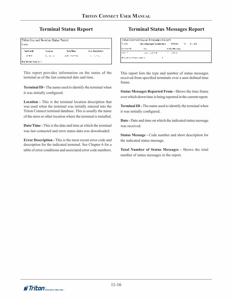
11-16
triton ConneCt User ManUal
This report lists the type and number of status messages received from specified terminals over a user-defined time frame.
Status Messages Reported From - Shows the time frame over which down time is being reported in the current report.
Terminal ID - The name used to identify the terminal when it was initially configured.
Date - Date and time on which the indicated status message was received.
Status Message - Code number and short description for the indicated status message.
Total Number of Status Messages - Shows the total number of status messages in the report.
Terminal Status Report Terminal Status Messages Report
This report provides information on the status of the terminal as of the last contacted date and time.
Terminal ID - The name used to identify the terminal when it was initially configured. Location - This is the terminal location description that was used when the terminal was initially entered into the Triton Connect terminal database. This is usually the name of the store or other location where the terminal is installed. Date/Time - This is the date and time at which the terminal was last contacted and error status data was downloaded.
Error Description - This is the most recent error code and description for the indicated terminal. See Chapter 6 for a table of error conditions and associated error code numbers.

11-17
Chapter 11 - reports Manager
This report provides information on the status of the terminal The Terminal Totals Report is used to report financial information accumulated from Day Close to Day close. If day Closes are not being performed, the totals will be cumulative.
Terminal ID - The name used to identify the terminal when it was initially configured.
Debits - This is the number of checking and savings account withdrawal transactions that have taken place since the last Day Close operation was performed.
Credits - This is the number of credit card withdrawal transactions that have taken place since the last Day Close operation was performed.
Inquiries - This is the number of balance inquiries performed by the terminal since the last Day Close operation was performed.
Transfers - This is the number of account transfer transactions performed by the terminal since the last Day Close operation wa performed.
Debit Amount - Total monetary value of all Debit transactions that have taken place.
Credit Amount - Total monetary value of all Credit transactions that have taken place.
Totals - Total of all values for all terminals listed in the Terminal Totals Report.
Terminal Totals Report Version Numbers Report
This report provides information on hardware versions for all terminals reporting information to Triton Connect.
Terminal ID - The name used to identify the terminal when it was initially configured.
Model # - This is the model number of the indicated terminal.
Eprom Version # - The Eprom holds software downloading, initialization, testing and low-level interface routines. This is the version number of the Eprom chip currently installed in the terminal.
Program Version # - The “Program” is the terminal operating software, which is downloaded to the terminal either locally or remotely via Triton Connect. This entry is the version number of the software currently loaded in the terminal.
Table/Screen Version # - The term “Table” refers to the software component that provides the ATM user interface and associated terminal control functionality. Because X-Scale terminals do not have a Table file but instead have a Screen file, the Version report was changed to reflect this column header.
Printer Version # - Printer version number. Availability of this data depends upon the version of ATM software running in the terminal.
SPED Version # - Version number of the SPED firmware. Availability of this data depends upon the version of ATM software running in the terminal.
Dispenser Version # - Dispenser version number. Availability of this data depends upon the version of ATM software running in the terminal.
Total Number of Terminals - This is the total number of terminals in the current Version Numbers Report.
Total Number of Terminals = 5

11-18
triton ConneCt User ManUal
this page intentionally left Blank

Chapter 12 - Software DownloaD

triton ConneCt USer ManUal
12-2
Introduction
Triton Connect can perform remote software down-loads to terminals.
In this chapter, we’ll show you how to access this func-tion.
Accessing the SoftwareDownload Function
Follow these steps to access the Software Downloadfunction:
1. Start the Terminal Manager application using theSupervisor password.
2. From the Utilities menu, select the Software Downloadoption. The Load Terminal Software screen appears:
Downloading SoftwareThe Load Terminal Software screen is similar in overallappearance to other terminal data screens in Triton Con-nect. Note that most of the data fields serve only to help identify and locate the terminal you want to work with.The Terminal ID list provides a quick way to select aparticular terminal. If there are many terminals, it may be more convenient to use the Search or Fil-ter features to locate a particular terminal or re-duce the number of terminals displayed in the list.
*** CAUTION ***
When you check this option, the terminal’s existingparameters will be erased and replaced with thevalues contained in the software load file! The ter-minal will then need to be reconfigured to yourspecifications, including re-enabling Triton Connect!
Follow these steps to initiate a software download:
1. Select the ID of the terminal you want to load withsoftware. If applicable, select the Broadcast option toselect multiple terminals.
2. Click the Select File button and use the file browserwindow to locate the download file you want to use.3. Choose the appropriate download options, asapplicable.
4. Click the Send File button. When the call schedulingwindow appears, schedule a time for the download andclick the OK button.
Download Options Z180 ATMs Only
There are three download options available. Use them asneeded to make changes to the way the download isnormally performed. These options are described next.
Include EEPROM Parameters
Parameters are stored in the terminal’s EEPROM, andspecify particular operational conditions, or providenecessary operating information for the terminal.
Normally, during initial software load at the factory theterminal is loaded with default parameter values. These are subsequently modified during the installation of the terminal, to fit specific operational requirements.
EPROM ACCESS CODE
When you select the Send option to schedule asoftware download, you will be prompted to enterthe terminal’s EPROM Access Code (if the terminalis running Z180 version 5.0 ATM software or greater),unless the code was entered when the terminal wasinitially added to the database

Chapter 12- Software DownloaD
12-3
Erase EEPROM Prior to LoadNormally this option is grayed out until the ‘IncludeEEPROM Parameters’ option is checked. Once active, you can check the option to specify erasure of the ter-minal’s EEPROM prior to loading the parameters con-tained in the software load file.
Force Tricomm DownloadIn the event that a software download to a terminal run-ning Z180 version 5.0 software or greater is unsuccessful, you can check this option to force a download using the Tricomm protocol. This type of download will require the assistance of support personnel at the terminal location.
TRICOMM DOWNLOADSTricomm is a separately available, PC-based utilitythat is used to load terminal software. It is typicallyinstalled on a PC or laptop computer, which is placedat the terminal location and physically connected tothe terminal by a serial cable (8-bit machines).
Tricomm-type downloads require the EPROM Access Code be manually entered at the terminal. Once access is granted, a special menu is used to configure the terminal to accept the software down-load.
For instructions on performing this type ofdownload, see the operating instructions that camewith the Tricomm utility or the ATM service manual.
RECOGNIZING TERMINAL TYPES
If the terminal has previously been contacted andparameters from the terminal have been received andstored in the database, Triton Connect will have theinformation it needs to automatically choose thecorrect software download type to use.
When the terminal is running Z180 version 5.0 software or greater, an unattended remote down-load will be attempted
* NOTE *Forced Tricomm downloads will not be allowed when TCP/IP or VSAT connection types are being used by the selected terminal and will display an error message
LOAD FILE FORMAT
For Load file Formats, refer to the table below.
TERMINAL-SPECIFIC LOAD FILE SELECTIONTo access the Software Download dialog, highlight theUtilities menu on the Terminal Manager menu bar, then select Software Download.
When you click the Select File button on the SoftwareDownload dialog, the application will display an OpenLoad File dialog box. The file type displayed will de-pend on the Terminal ID you selected. If the applica-tion identifies the terminal as an X2 terminal, load files with the .TFV. file extension will be displayed.
If the version information identifies the terminal as an XScale or Z-180, the dialog will display the file formatsshown in.
Note: If you have not downloaded parameters for theselected terminal, the system will display an errormessage and prompt you to download parameters for the selected X2 terminal.
EEE value EEE meaningtlf XScaletlv X2 CE 5tr6 X2 CE 6tr7 X3 CE 7

triton ConneCt USer ManUal
12-4
FILE FORMAT VALIDATIONOnce you’ve selected a load file with a TFV extension andhave pressed the Open button, the application will startthe file validation process. If the file is determined to be avalid TFV load file, the Open Load File dialog box willclose and return you to the Software Download dialogmain form. This proccess will validate all file types (tlf, tfv, tr6 and tr7).
If the load file is not valid, the application will display anerror message
When you acknowledge the error by pressing the OK button you will be returned to the Software Download dialog main form.
NOTE: The extension could also be tr6 or tr7 depend-ing on the ATM model that was selected.

Chapter 13 - aD Designer

13-2
triton ConneCt User ManUal
Introduction
The Ad Designer is used to combine bit-mapped graphics and text together to create Ad Screens for non-PC based units. Triton Connect is used to download these Ad Screens to selected terminals for display.
The Ad Designer is an editing utility that is used to import and manipulate bit-mapped graphics (in the BMP format) to create Graphic Ad Screens. Additional tools enable the merging of text with bit-mapped images or the creation of text-only Ad Screens.
Ad Screen Characteristics
The Ad Designer can only import and manipulate bit-mapped graphic images; it cannot create them. You must use a third-party graphics application to initially create the graphic images you wish to use as Ad Screens.
In creating your graphics, ensure the images conform to the following requirements:
• Theimagesmustbeeither16-coloror256-color.
• Eachimagemustbeno larger than320pixelswideby 240 pixels high (these limits represent thedimensions of the terminal display screen).
TheWindowsPaintapplicationcreatesbitmapfiles inageneric format that is fully compatible with the Ad Screen capability of the terminal, and should enable you to meet the above requirements. If you decide to use another graphics program to create your bitmapped images it is recommendedthatbeforeprocessingthefilewiththeAdDesigner,youopenandthenre-savethefileusingWindowsPaint, to ensure maximum compatibility with the terminal.
* NOTE *Graphic Ad Screens can only be downloaded to terminals equippedwith one ormore ExpansionMemorymodules (96XX).Text-onlyAdScreensdonot require this additional storage memory.
AD SCREEN SIZE
Whyamaximumimagesizeof320-by-240pixels?This is the size of the LCD display on the terminal; therefore, images must be no larger than these dimensions in order to be completely visible. In fact, the Ad Designer will not allow you to use images larger than these dimensions.
Youcanfindareminderofthemaximumpixelsizeof the image under the Help/Help option on the menu bar:
This message box also shows the allowable color-depthvaluesallowedforAdScreenimages:16-coloror256-color.
* NOTE *Thefilenameoftheimagemustbenolongerthaneight characters (not including the period andfilename extension).
** IMPORTANT ** F I LE NAMES MUST CONS I S T O FALPHANUMERICCHARACTERSONLY!TritonConnectwillnottransferfilestoaterminalifthosefileshavenamesthatcontainnon-alphanumericcharacters.UseonlythecharactersA-Z(upperorlowercase)andthenumbers0-9;anyothercharacterswill prevent Triton Connect from downloading the graphicstotheterminal.Onlythedisplayschedulewill be sent, resulting in the display of blank screens ontheterminalatscheduledtimes!

13-3
Chapter 13 - aD Designer
Accessing the Ad Designer
Follow these steps to access the Ad Designer:
1. Start the Terminal Manager application.
2. FromtheUtilitiesmenu,selecttheAdDesigneroption.The Ad Designer screen appears:
Ad Designer Features
This section provides a brief outline of the functions of the Ad Designer.
Menu
The primary options available through the menu bar allow youtoopenandsavegraphicsfiles,placegraphicimageswithin the display area, clear the display area, and set the Ad Screen display duration (how long each Ad Screen will be displayed on the terminal screen).
Additional options enable you to see the color-depth (16-coloror256-color)oftheimagecurrentlybeingviewedin the display window, to view various help displays, and to restore warning messages.
Display Window
The Ad Designer enables you to manipulate Ad Screen content (graphic and text entities) as discrete “objects.” This gives you the ability to select individual components of an Ad Screen for various editing operations.
The Display Window is where you will compose your Ad Screen. You can place both text and graphic elements within the display area, positioning those elements as needed to createthefinalAdScreencomposition.
The text-entry area below the display window provides a place to enter any textual words or phrases you need to add to an existing graphic or to create a text-only Ad Screen.
TEXT VS. GRAPHIC AD SCREENSGraphics Ad Screens will take priority over text-based screens in a terminal. If the terminal has been equippedwith one ormore optional ExpansionMemory Modules, and is running Graphics Ad Screens, no text-based screens will be displayed.
If no Graphics Ad Screens are loaded in the terminal, or if the Ad Screen function has been turned off (via Triton Connect or by local terminal control), Text Ad Screens, if loaded, will be displayed.
This behavior allows you to design both graphic and text versions of Ad Screens, which can then be broadcast to a group of terminals. Those terminals that support graphics will automatically display the graphics versions of the Ads, while terminals not equipped (or not enabled) to display graphics Ads will automatically display the text-based versions.

13-4
triton ConneCt User ManUal
TheRedrawScreenbutton enables you to “refresh” thedisplay as needed during editing operations.
Text Display Options
Several text display options can be changed to make Ad Screen text appear more distinctly within the display. The options include:
• Reverse Text. Checking this option reverses the foreground and background color selections in the text object.
• Transparent Text. Checking this option allows you to place text directly on a BMP graphic without erasing theimagebehindthetext.Thetextwillappearto“float” over the underlying image.
• Foreground Color. This button calls up a display of the currently available colors that can be applied to the next text entry. These colors are based on the “palette” of colors available within the currently displayed image. If no image is displayed, a default set of colors will be available to choose from.
• Background Color. Select one color from a color pallet of sixteen colors. As with the Foreground Color, this color is also chosen from the current palette.
• Font Size. Small, Medium, or Large.
Creating an Ad Screen
Follow these procedures to create an Ad Screen:
1. Click the Place BMP selection of the Menu Bar. This displaysaBMPfileselectionwindow.
2. Select the BMP graphic by either double clicking on thedesiredBMPfilename,orbyclickingonthefilename to highlight it and then clicking Open.
CREATING TEXTBecause theTextDisplayOptionsprovideonlyabasicsetofconfigurationsettings,youmaywanttoconsider using a separate graphics application to add text directly to your Ad Screen bitmaps.
Most commercial graphics programs enable you to select from many typeface and font size options, offering a wider range of creative choices in the creation of your Ad Screens.

13-5
Chapter 13 - aD Designer
TURNING WARNING MESSAGES ON AND OFF
The warning messages that appear when graphics or text are selected can be turned off, so that subsequent operations are not interrupted by the appearance of these screens.
A check box appears at the bottom of each screen. This option allows you to turn off the display of that particular warning screen. Click the check box to enable:
To turn all currently disabled warning messages back on,usetheEnableMessagesoption,whichcanbeaccessed from the Help menu.
SWITCHING BETWEEN 16-COLOR AND 256-COLOR IMAGES
If you want to know the color depth of the image currently visible in the display area, select the Window option from the menu bar:
A check mark will appear next to the type of image currently being displayed. If a second image has been loaded into the display area, you can switch to it by clicking on the appropriate image type.
3. The Ad Designer will evaluate the “color depth” (number of colors in the image) of the image and will present either of two warning messages to you; which message is displayed will depend upon whether the imageisa16-coloror256-colorbitmap.
For 16-Color Images:
This screen will give you the option to proceed with the selectionofthe16-colorbitmapimage,ortoreturntothefile-selectiondialogtoselecta256-colorbitmapimage.
You can take this opportunity to consider the type of terminal the image is to be displayed upon. If the terminal hasa16-colordisplay,a16-colorAdScreenis theonlycorrectchoice,inwhichcaseyouwouldclicktheDON’TSELECT256-COLORBMPoption.Theselected imagewill appear in the display area.
However,iftheterminalusesa256-colordisplay,youmayalsowishtoselectanother,256-colorimage.Thismaybeaversionofthefirst,16-colorimage,oracompletelydifferentimage. In this case, choose the SELECT256-COLORBMPoption.Youwillbepresentedwiththefileselectiondialog,whichwillallowyoutochoosea256-colorimage.Bothimageswillbeloadedintothedisplayarea.Thefirstimage(16-color)willbevisible,whilethesecondimage(256-color)willbehidden.Youcanswitchbetweenimagesusing the Window option on the menu bar (see the sidebar for more detail).
Ofcourse,a256-colordisplaycanalsodisplaya16-colorimage (although there will be no improvement in the image),soiftheterminalusesa256-colordisplayeither16-coloror256-colorimagesmaybeused.
For 256-Color Images:

13-6
triton ConneCt User ManUal
This screen will give you the option of proceeding with theselectionofthe256-colorbitmapimage,orofoptingto return to thefile-selectiondialog in order to select a16-colorbitmapimagetoworkonaswell.
Iftheterminalhasa16-colordisplay,youwillhavetoselecta 16-color image instead, since terminalswith 16-colordisplayscannotdisplay256-colorimagescorrectly.Inthiscase,choosetheSELECT16-COLORBMPoption.Youwillthenbepresentedwiththefileselectiondialog,whichwillallowyoutolocateandselecta16-colorimage.Bothimageswillbeloadedintothedisplayarea.UsetheWindowoption to select the image you wish to work on.
Iftheterminalhasa256-colordisplay,choosetheDON’TSELECT16-COLORBMPoption to proceedwith theoperation. The selected image will appear in the display area.
4. The BMP graphic will appear in the display area. To move the graphic, click on the image while holding down the left mouse button and drag the graphic to the desiredlocation.Notehowtheimageisreplacedbyablack bounding-box during the dragging operation.
5. Toplacetextwiththegraphic,firsttypethetextthat
you want to appear with the graphic into the text box.
6. Next,usetheTextDisplayOptionstochangethetextcharacteristics (transparency, foreground/background colors,fontsize,etc.)asyouseefit.
7. Move the mouse cursor to the point where you want the text to appear on the Ad Screen and click the left mousebutton.Thefirsttimetextisaddedtotheimagethe following warning message will appear:
The primary purpose of this screen is to offer a caution concerningthedisplayoftextonterminalswith256-colordisplays.Text will not be correctly displayed on such terminals.
To avoid these occurrences, it is recommended that you add text to the bitmap image using a third-party graphics application. This will create a combined bitmap image which can then be converted to an Ad Screen. Images created in thiswaywill display correctly on 256-colorterminals.
TEXT-ENTRY LIMITATIONSThetextyouenterdoesnotwrap.Eachlineoftextmust be entered individually.
UsingSmall/Mediumfontselection,approximately30characterswillfitononeline;usinglargefont,approximately 20 characters.Ten tofifteen linesof textwillfitverticallywithin the imagedisplaywindow, depending on the font size.

13-7
Chapter 13 - aD Designer
PROBLEMS WITH TEXT ON256-COLOR DISPLAYS
Toavoidtextdisplayproblemson256-colordisplaysyou should use a graphics application to add text directly to your Ad Screen bitmaps. You may also wishtocreateyour16-colorAdScreens(thatincludetext) in this way.
An advantage of this technique is that most commercial graphics programs enable you to select from many typeface and font size options, offering a wider range of creative choices in the creation of your Ad Screens.
CREATING TEXT-ONLY AD SCREENSTo create text-only Ad Screens, simply place the text you want in the display area and save the image (seeStep10).
The .TCGfile that iscreatedby thisprocesswillcontain the text of the Ad Screen.
Text and 16-color graphics can be combined in theAdDesignerandwilldisplayon16-colorterminals.
SelectOKtoaddthetexttothedisplay.Thetextwillbedisplayed on the screen using the current text options. Move the text by placing the cursor over the text, then clicking and holding the left mouse button. Drag the text to the desired location and release.
If you wish, add additional text objects to the Ad Screen by repeatingSteps5-7.Upto28textobjectscanbeaddedtothe bitmap, or placed in a text-only Ad Screens.
8. Todeletethegraphicoratextobject,placethemouse
cursor on the item and click the right mouse button. A confirmationboxwillappear.
Notethattheselectedobjecthasbeenassignedanumber.The bitmap image is assigned object number 1 by default. Text objects are numbered from 2 to 29.
To delete the selected object, choose theOK option;otherwise, select Cancel to return to the display area window.
9. Select the Display Duration option from the menu:
Choose a display duration for the Ad Screen. This is the number of seconds the image will be displayed on the terminal screen. Ad Screens are repeatedly displayed on the terminal screen using a “looping” system.
10. OncetheAdScreengraphiciscompleted,saveitbyselecting the File optionon the menu bar, then clicking on Save As.
NamethefileandclicktheSavebutton.ATritonConnect

13-8
triton ConneCt User ManUal
Graphic (TCG) format will be created.
Ads created in the Ad Designer can be set up for download to a terminal using the Ad Graphics/File Manager tab in theTerminal Parameters area (seeChapter 8,TerminalParameters, for details).
ABOUT TCG FILESThe.TCGfileholdsinformationaboutthelayout,content and characteristics of an Ad Screen.
1. The.TCGfilecontainsanytextthatwasaddedto the Ad Screen image, including all text-formatting information.
2. The.TCGfilecontainsapointertotheoriginalbitmap image (if any) that was used in the creation of the Ad Screen.
3. The.TCGfilealsocontainsthedisplaydurationparameter.
** IMPORTANT **Do not move, rename, or otherwise alter the original bitmapfilethatwasusedtocreatetheAdScreen!Todo so can prevent Triton Connect from downloading thefiletotheterminal!
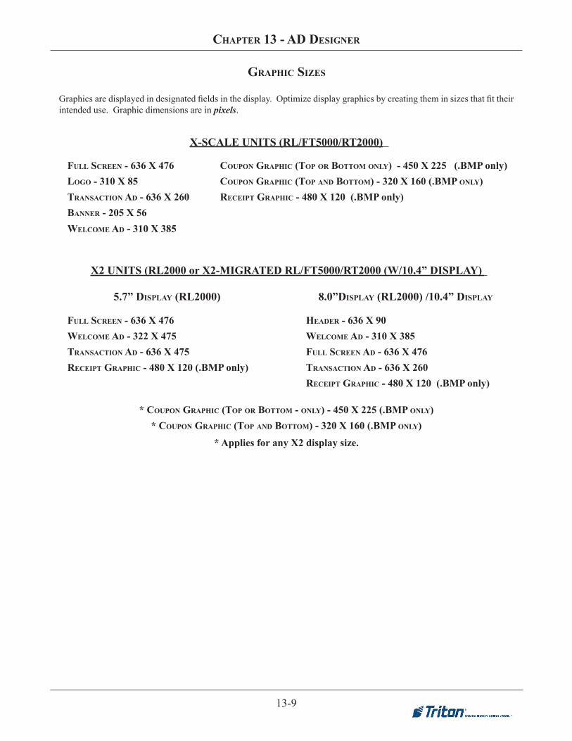
13-9
Chapter 13 - aD Designer
Graphicsaredisplayedindesignatedfieldsinthedisplay.Optimizedisplaygraphicsbycreatingtheminsizesthatfittheirintended use. Graphic dimensions are in pixels.
FUll sCreen - 636 X 476logo - 310 X 85transaCtion aD - 636 X 260Banner - 205 X 56
heaDer - 636 X 90WelCoMe aD - 310 X 385FUll sCreen aD - 636 X 476transaCtion aD - 636 X 260reCeipt graphiC - 480 X 120 (.BMP only)
X-SCALE UNITS (RL/FT5000/RT2000)
X2 UNITS (RL2000 or X2-MIGRATED RL/FT5000/RT2000 (W/10.4” DISPLAY)
FUll sCreen - 636 X 476WelCoMe aD - 322 X 475transaCtion aD - 636 X 475reCeipt graphiC - 480 X 120 (.BMP only)
5.7” Display (rl2000)
WelCoMe aD - 310 X 385
* CoUpon graphiC (top or BottoM - only) - 450 X 225 (.BMp only)* CoUpon graphiC (top anD BottoM) - 320 X 160 (.BMp only)
8.0”Display (rl2000) /10.4” Display
CoUpon graphiC (top or BottoM only) - 450 X 225 (.BMP only)CoUpon graphiC (top anD BottoM) - 320 X 160 (.BMp only)reCeipt graphiC - 480 X 120 (.BMP only)
* Applies for any X2 display size.
graphiC sizes

13-10
triton ConneCt User ManUal
LOGO310 x 85
BANNER205 x 56
WELCOME AD310 x 385
graphiC eXaMples
TRANSACTION AD636 x 260
HEADER (X2)636 X 90
FULL SCREEN636 x 476

CHAPTER 14 - COUPON UTILITY

14-2
TRITON CONNECT USER MANUAL
Introduction
The Coupon Utility is used to manage the graphic imagesand display parameters associated with the CouponSelection feature of Triton Systems ATMs. The CouponSelection feature, which is available at the conclusion ofan ATM transaction, enables the customer to select a couponof their choice from a graphical menu screen. The selectedcoupon is immediately printed by the ATM receipt printer.Each coupon has a graphic image associated with it, whichis printed on the receipt. Triton Connect is used to downloadthese bitmap images and display parameters to selectedterminals.
The Coupon Utility is used to import and assign bitmapgraphics to the Coupon Selection Screen, to assignindividual receipt coupon graphic images to up to six menuselections and to establish the display duration of theCoupon Selection Screen. These selections are stored in afile called a Triton Connect Coupon, or .TCC file.
Accessing the Coupon Utility
Follow these steps to access the Coupon Utility:
1. Start the Terminal Manager application.
2. From the Utilities menu, select the Coupon Utilityoption. The Coupon Utility screen appears:
Coupon Image Characteristics
The Coupon Utility cannot create bitmap images: it canonly import them. You must use a third-party graphicsapplication (such as the Paint utility that is included inMicrosoft Windows) to initially create the images you wantto use as the Coupon Selection Screen graphic and ReceiptGraphic images. The images you create must conform tospecific requirements, as outlined below.
Coupon Selection Screen
The Coupon Selection Screen image must conform to thesespecifications:
• The image must be either 16-color or 256-color. If theimage is NOT either 16 or 256 colors it will be rejected!
• The image must be 320 pixels wide by 240 pixels high.If the image is NOT 240-x-320 it will be rejected!
** IMPORTANT **Do not move, rename, or otherwise alter the originalbitmap files associated with the .TCC file. To do socan prevent Triton Connect from downloading thefiles to the terminal!
ABOUT TCC FILES
The .TCC file that is created as the final step of theTriton Connect Coupon file creation process is aspecially-formatted data file that holds informationdescribing the content and display duration of theCoupon Selection Screen.
The .TCC file contains pointers to the bitmap imagesof the Coupon Section Screen and the ReceiptGraphics.
* NOTE *The Coupon Selection feature is an optional featurethat may not be available on all ATMs.
** IMPORTANT **This option is ONLY available on terminalswithsoftware that supports this feature.

14-3
CHAPTER 14 - COUPON UTILITY
Receipt Graphics
Each Receipt Graphic image must conform to the followingrequirements:
• The image must be monochrome (black and white)format. If the image is not monochrome it will will not be available for selection as a Receipt Graphic!
• The image must be no larger than 380 pixels wide by700 pixels high. If the dimensions of the image aregreater than these limits the image will not be available for selection as a Receipt Graphic!
Coupon Utility Features
This section provides a brief outline of the features of theCoupon Utility.
Menu
The menu bar options allow you to:
1. File. Open and save Triton Connect Coupon (.TCC)files.
2. Place BMP. Place Coupon Selection Screen graphicsinto the display area.
3. Clear Screen. Clear the screen of the current CouponSelection Screen and Receipt Graphic selections.
4. Remove BMP. Remove the Receipt Graphic associatedwith a Coupon Button.
5. Window. See the color-depth (16-color or 256-color)of the Coupon Selection Screen image currently beingviewed in the display window. Also allows you toswitch between the 16-color or 256-color versions ofthe image.
Display Window
1. Display Window. This is where the selected CouponSelection Screen will appear.
2. Menu Buttons. Buttons 1-3 and 5-7 are used to selecta monochrome bitmap image for printing on theselected receipt coupon.
3. More/Cancel. Represent the functions available to thecustomer at the ATM. The More button allows the userto switch to the next Coupon Selection Screen and setof Receipt Graphic menu selections. The Cancel buttonreturns the customer to the previous Coupon SelectionScreen, or to the ATM Welcome screen (if currentlyon the first Coupon Selection Screen).
HOW MANY MENU LEVELS?
If multiple coupon screens are available the customerwill use the MORE and CANCEL buttons tonavigate through the various coupon selectionmenus.
Each Triton Connect Coupon (.TCC) file you createin the Coupon Utility can reference ONE CouponSection Screen and up to SIX Receipt Graphicimages. Downloading multiple .TCC files to aterminal will provide multiple Coupon SelectionScreens to the customer. The number of .TCC files/graphics that can be stored on the terminal dependsupon the amount of available memory on the selectedexpansion memory card.
To conserve memory for use by Ad Graphics it isrecommended that no more than two .TCC files perinstalled memory card be downloaded to theterminal.
For more information on downloading files to theterminal see the Ad Graphics/File Manager topic inChapter 8, Terminal Parameters.

14-4
TRITON CONNECT USER MANUAL
4. Display Duration. Used to select the length of Creatinga Triton Connect Coupon File
Creating a Triton Connect Coupon File
Follow these procedures to create a Triton Connect Couponfile:
1. Click the Place BMP selection of the Menu Bar. Thisdisplays a BMP file selection window. Use it to locatethe bitmap file you want to use.
2. Select the BMP graphic by either double clicking onthe desired BMP file name, or by clicking on the filename to highlight it and then clicking OK.
3. The Coupon Utility will evaluate the “color depth”(number of colors in the image) of the image and willpresent either of two messages to you; which messageis displayed will depend upon whether the image is a16-color or 256-color bitmap.
For 16-Color Images:
This screen will give you the option to proceed with theselection of the 16-color bitmap image, or to return to thefile-selection dialog to select a 256-color bitmap image.
You can take this opportunity to consider the type of terminalthe image is to be displayed upon. If the terminal has a 16-color display, a 16-color Coupon Selection Screen is theonly correct choice, in which case you would click theDON’T SELECT 256-COLOR BMP option. The selectedimage will appear in the display area.
However, if the terminal uses a 256-color display, you mayalso wish to select another, 256-color image. This may be aversion of the first, 16-color image, or a completely differentimage. In this case, choose the SELECT 256-COLOR BMPoption. You will be presented with the file selection dialog,which will allow you to choose a 256-color image. Bothimages will be loaded into the display area. The first image(16-color) will be visible, while the second image (256-color) will be hidden. You can switch between images usingthe Window option on the menu bar (see the sidebar formore detail).
Of course, a 256-color display can also display a 16-colorimage (although there will be no improvement in the image),so if the terminal uses a 256-color display either 16-coloror 256-color images may be used.
LOCATION OF FILESThe file selection window allows you to locate andselect Coupon Selection Screen files from anywhereon your PC. Once selected, these files will beautomatically copied into the .BMP sub-folder ofthe Triton Connect installation folder.
TURNING WARNING MESSAGES ON / OFFThe warning messages that appear when graphicsor text are selected can be turned off, so thatsubsequent operations are not interrupted by theappearance of these screens.
A check box appears at the bottom of each screen.This option allows you to turn off the display of thatparticular warning screen. Click the check box toenable:
To turn all currently disabled warning messages backon, use the Enable Messages option, which can beaccessed from the Help menu.

14-5
CHAPTER 14 - COUPON UTILITY
For 256-Color Images:
This screen will give you the option of proceeding with theselection of the 256-color bitmap image, or of opting toreturn to the file-selection dialog in order to select a 16-color bitmap image to work on as well.
If the terminal has a 16-color display, you will have to selecta 16-color image instead, since terminals with 16-colordisplays cannot display 256-color images correctly. In thiscase, choose the SELECT 16-COLOR BMP option. Youwill then be presented with the file selection dialog, whichwill allow you to locate and select a 16-color image. Bothimages will be loaded into the display area. Use the Windowoption to select the 16-color image to work on.
If the terminal has a 256-color display and you do not wishto load another, 16-color bitmap, choose the DON’TSELECT 16-COLOR BMP option to proceed with theoperation. If you wish to load a 16-color image as wellchoose the SELECT 16-COLOR BMP option. Both images
will be loaded into the display area. The first image (256-color) will be visible, while the second image (16-color)will be hidden. You can switch between images using theWindow option on the menu bar.
4. Choose a Display Duration for the currently displayedCoupon Selection Screen. This is the number ofseconds the image will be displayed on the terminalscreen before returning to the terminal’s customerwelcome screen. The duration can be set from 10-255seconds.
5. Now you will assign Receipt Graphic images to one ormore Coupon Buttons. Buttons 1-3 and 5-7 can eachhave an associated graphic assigned. When thecustomer presses a Coupon Button on the terminal, theassociated graphic will be printed on a receipt. Thecustomer will only be able to select one coupon itemper ATM transaction.
To begin, click a Coupon Button (1-3 or 5-7). A file selectionwindow will appear. Use this window to locate and select apreviously created graphic file that conforms to thespecifications listed in the section on Image Characteristics.When viewing files only images that are monochrome and380-x-700 pixels will be visible. Once selected, theimage filename will appear in the button caption, asin this example:
6. Repeat Step 5 for any remaining Coupon Buttons youwish to assign.
7. Once the Coupon Selection Screen graphic, ReceiptGraphic(s) and Display Duration have been set, savethe settings by selecting the File option on the menubar, then clicking Save As.
A dialog box will appear. Enter a maximum eight-character name for the file and click the Save button.A file in the Triton Connect Graphic (.TCC) formatwill be created in the .BMP sub-folder of the TritonConnect installation folder.
8. Use the Ad Graphics/File Manager function todownload the coupon file to selected terminals (seeChapter 8, Terminal Parameters, for details on thisprocedure).
SWITCHING BETWEEN16-COLOR AND 256-COLOR IMAGES
If you want to know the color depth of the imagecurrently visible in the display area, select theWindow option from the menu bar:
A check mark will appear next to the type of imagecurrently being displayed. If a second image has beenloaded into the display area, you can switch to it byclicking on the appropriate image type.

14-6
TRITON CONNECT USER MANUAL
THIS PAGE INTENTIONALLY LEFT BLANK

CHAPTER 15 - SSL SUPPORT
SSL Support
Triton Connect adds support for SSL for secure communications. To use this feature, a SSL certificate must be acquired from a Certificate Authority such as VeriSign. If there is already a suitable certificate on the Triton Connect server, it may be used. A list of Certificate Authorities support by the ATM is below:
• VeriSign/RSA Secure Server
• VeriSign Class 1 Public Primary CA
• VeriSign Class 2 Public Primary CA
• VeriSign Class 3 Public Primary CA
• GTE Cybertrust ROOT
• ThawtePremium Server CA
• Thawte Server CA
• Entrust.net Secure Server CA
• Entrust.net Premium Secure Server CA, also known as Entrust.net CA (2048) Note: In order to use SSL, both the ATM and Triton Connect must support SSL and must be
properly configured. If uncertain, please check with Triton technical support to verify if your
ATM software version supports SSL.
Create Certificate Signing Request
A Certificate Signing Request (CSR) is a request that is used to acquire a certificate. After an application generates a CSR, the CSR must be transmitted to a Certificate Authority during the process of applying for a certificate. For Triton Connect, a CSR only needs to be generated in order to obtain a new certificate for purposes such as initial setup or if the current certificate will soon expire. For the certificate to perform properly, the Common Name field used in the CSR must match the value entered into the ATM as the Triton Connect host in the Triton Connect configuration screen. To create a CSR, perform the following steps: 1. Open the Triton Connect Call Monitor. 2. From the main Call Monitor window, open the “Settings” menu. 3. From the Settings menu, select “SSL Settings”. 4. Click the “Create CSR” button on the “SSL Settings” dialog screen. 5. Enter the value for the Common Name of the certificate. This should be the same value as entered into
the ATM as the Triton Connect host in the Triton Connect configuration screen. 6. From the “CSR Request” window, click the “Generate” button. 7. Click the “Copy Text” button to copy the CSR. The CSR will be given to the Certificate Authority
during the process of acquiring a SSL certificate. After the Certificate Authority has completed any verification that may be required, a signed CSR will be given to the requestor.

9. Click the Close button to close this window.
SSL Settings selection in Settings menu
SSL Settings dialog with Create CSR
button shown CSR Request dialog prior to generating a CSR
Request.
CHAPTER 15 -
SSL SUPPORT
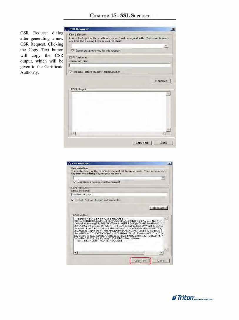
CSR Request dialog after generating a new CSR Request. Clicking the Copy Text button will copy the CSR output, which will be given to the Certificate Authority.

Import Certificate Signing Request After the selected Certificate Authority has processed the CSR and any other information they may require, a signed CSR will be given to the requestor. This may be done by emailing the signed CSR as either an attached file or as text that must be copied and pasted into Triton Connect, or it may be in the form of a file that must be downloaded from their website. Once the signed CSR has been successfully imported into Triton Connect, the process of acquiring a certificate is complete.
To import a CSR, perform the following steps: 1. Open the Triton Connect Call Monitor. 2. From the main Call Monitor window, open the “Settings” menu. 3. From the Settings menu, select “SSL Settings”. 4. Click the “Import CSR” button on the “SSL Settings” dialog screen. 5. From the Import Signed CSR window, either paste in the signed CSR by clicking “Paste Text”, or
browse for the certificate by file by clicking on the “Import Certificate from File” button.
6.After the signed CSR has been inserted into the window, click “Import” to proceed. If there are no problems, a success message will be shown and the window will be closed.
SSL Settings selection in Settings menu SSL Settings window with Import
CSR button shown
CHAPTER 15 - SSL SUPPORT

Import Signed CSR window Import Signed
CSR window after signed CSR has been
inserted.

CSR Imported Successfully
Message
Select
Certificate for
SSL
Connections Once the certificate has been installed on the PC, the correct certificate must be selected for use by Triton Connect. To select the SSL certificate, perform the following steps: 1. Open the
Triton Connect Call Monitor.
2. From the main Call Monitor window, open the “Settings” menu.
3. From the Settings menu, select “SSL Settings”. 4. From the SSL Settings window, click the “Select
Certificate” button. This will present the “Certificate Browser” window.
5. Browse the certificates until the desired certificate is found.
6. Once the proper certificate is found, click on it to and click the “Select” button. This will select the certificate and close the Certificate Browser window.
CHAPTER 15 - SSL SUPPORT

SSL Settings selection in
Settings menu
SSL Settings window with Select Certificate button shown Certificate Browser with certificate selected and Select button shown
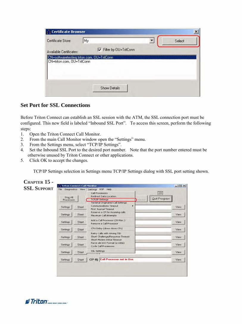
Set Port for SSL Connections
Before Triton Connect can establish an SSL session with the ATM, the SSL connection port must be configured. This new field is labeled “Inbound SSL Port”. To access this screen, perform the following steps: 1. Open the Triton Connect Call Monitor. 2. From the main Call Monitor window open the “Settings” menu. 3. From the Settings menu, select “TCP/IP Settings”. 4. Set the Inbound SSL Port to the desired port number. Note that the port number entered must be
otherwise unused by Triton Connect or other applications. 5. Click OK to accept the changes.
TCP/IP Settings selection in Settings menu TCP/IP Settings dialog with SSL port setting shown.
CHAPTER 15 -
SSL SUPPORT

Enable or Disable SSL
A selection was added to enable and disable SSL in Triton Connect. To change the enabled status of SSL, perform the following steps: 1. Open the Triton Connect Call
Monitor. 2. From the main Call Monitor
window, open the “Settings” menu.
3. From the Settings menu, select “SSL Settings”.
4. Check or uncheck the “Use SSL” checkbox to enable or disable SSL.
5. Click the OK button to accept the change and close the window.

SSL Settings dialog with checkbox to enable/disable SSL shown.
Accept SSL Connection Requests After performing all of the above steps, Triton Connect should be configured to accept an SSL connection from the ATM. Note that if SSL is being used on an ATM, Triton Connect callback is automatically enabled. In order to allow Triton Connect to accept SSL connection request after selecting the appropriate certificate, simply configure a Call Processor for TCP/IP as normal.
If an incoming call is using SSL, once SSL parameters have been negotiated the parameters will be
displayed in the Call Processor window as shown below.
SSL Parameters as shown in Call Processor window

䌀䠀䄀倀吀䔀刀.............
....................
....................
....................

APPENDIX A - TERMINAL PARAMETERS
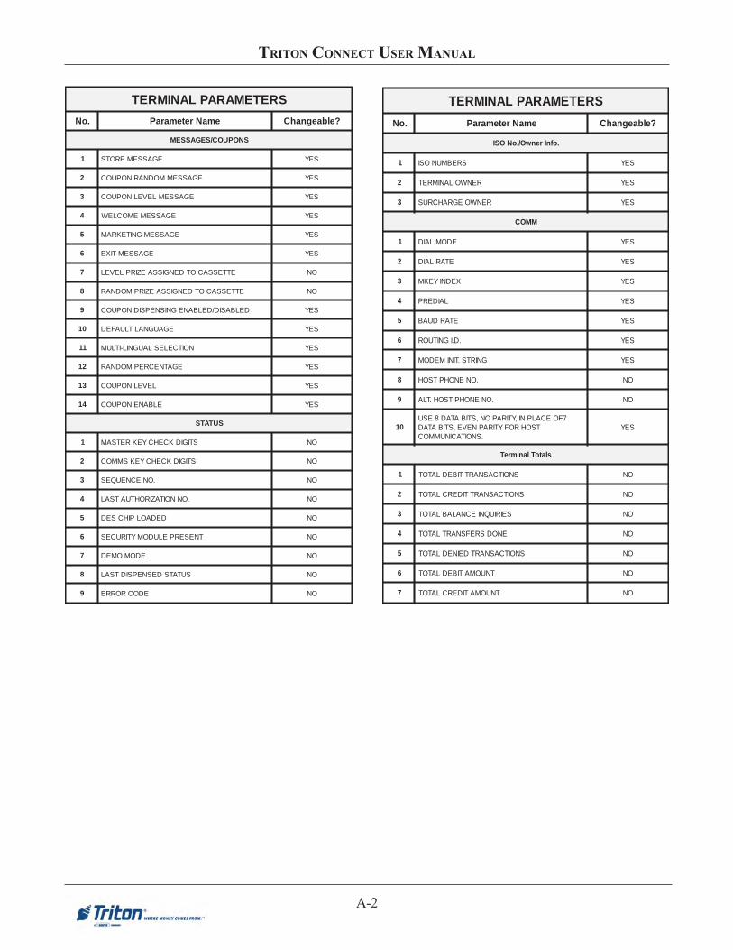
A-2
TRITON CONNECT USER MANUAL
SRETEMARAPLANIMRET
.oN emaNretemaraP ?elbaegnahC
SNOPUOC/SEGASSEM
1 EGASSEMEROTS SEY
2 EGASSEMMODNARNOPUOC SEY
3 EGASSEMLEVELNOPUOC SEY
4 EGASSEMEMOCLEW SEY
5 EGASSEMGNITEKRAM SEY
6 EGASSEMTIXE SEY
7 ETTESSACOTDENGISSAEZIRPLEVEL ON
8 ETTESSACOTDENGISSAEZIRPMODNAR ON
9 DELBASID/DELBANEGNISNEPSIDNOPUOC SEY
01 EGAUGNALTLUAFED SEY
11 NOITCELESLAUGNIL-ITLUM SEY
21 EGATNECREPMODNAR SEY
31 LEVELNOPUOC SEY
41 ELBANENOPUOC SEY
SUTATS
1 STIGIDKCEHCYEKRETSAM ON
2 STIGIDKCEHCYEKSMMOC ON
3 .ONECNEUQES ON
4 .ONNOITAZIROHTUATSAL ON
5 DEDAOLPIHCSED ON
6 TNESERPELUDOMYTIRUCES ON
7 EDOMOMED ON
8 SUTATSDESNEPSIDTSAL ON
9 EDOCRORRE ON
SRETEMARAPLANIMRET
.oN emaNretemaraP ?elbaegnahC
.ofnIrenwO/.oNOSI
1 SREBMUNOSI SEY
2 RENWOLANIMRET SEY
3 RENWOEGRAHCRUS SEY
MMOC
1 EDOMLAID SEY
2 ETARLAID SEY
3 XEDNIYEKM SEY
4 LAIDERP SEY
5 ETARDUAB SEY
6 .D.IGNITUOR SEY
7 GNIRTS.TINIMEDOM SEY
8 .ONENOHPTSOH ON
9 .ONENOHPTSOH.TLA ON
017FOECALPNI,YTIRAPON,STIBATAD8ESU
TSOHROFYTIRAPNEVE,STIBATAD.SNOITACINUMMOC
SEY
slatoTlanimreT
1 SNOITCASNARTTIBEDLATOT ON
2 SNOITCASNARTTIDERCLATOT ON
3 SEIRIUQNIECNALABLATOT ON
4 ENODSREFSNARTLATOT ON
5 SNOITCASNARTDEINEDLATOT ON
6 TNUOMATIBEDLATOT ON
7 TNUOMATIDERCLATOT ON

A-3
APPENDIX A - TERMINAL PARAMETERS
SRETEMARAPLANIMRET
.oN emaNretemaraP ?elbaegnahC
sneercSdAtxeT
1 EGASSEMTXET SEY
2 NOITARUDYALPSID SEY
3 NEERCSDETCELES SEY
stnuomA
1 TNUOMALAWARDHTIW.XAM SEY
2 1HSACTSAF SEY
3 2HSACTSAF SEY
4 3HSACTSAF SEY
5 4HSACTSAF SEY
6 5HSACTSAF SEY
7 NOITANIMONED ON
tatSettessaC
1 SNOITCASNARTLATOT ON
2 DEDAOLHSAC ON
3 STNEVETCEJER ON
4 STNUOMADESNEPSID ON
5 GNINIAMERHSAC ON
srebmuNnoisreV
1 .ONLEDOM ON
2 .ONNOISREVMORPE ON
3 .ONNOISREVMARGORP ON
4 .ONNOISREVELBAT ON
SRETEMARAPLANIMRET
.oN emaNretemaraP ?elbaegnahC
reganaMeliF/scihparGdA
1 ’SRETEMARAPDNES’RETFANIAMEROTSELIF SEY
2 SNEERCSTNEMESITREVDAELBANE SEY
3 LANIMRETNOSELIFGNITSIXEETIRWREVO SEY
4 1DRACYROMEMTAMROF-ER SEY
5 2DRACYROMEMTAMROF-ER SEY
6 GNILUDEHCS SEY
7 )NOITCNUFRENGISEDDA(DATIDE/WEIV SEY
scihparGretnirP
1 EPYTTPIECER SEY
2 NOITACIFITSUJ SEY
3 NOITACOL SEY
4 LANIMRETEHTNOSELIFGNITSIXEETIRWREVO SEY
5 STPIECERNOGNITNIRPCIHPARGELBANE SEY
sgnitteSdecnavdA
1 DELBANESEIRIUQNIECNALAB SEY
2 DELBANESNOITCASNARTTNUOCCASGNIVAS SEY
3 DELBANESNOITCASNARTDRACTIDERC SEY
4 DELBANESREFSNART SEY
5 REDAEHSMMOCEDULCNI SEY
6 SUTATSLANIMRETEDULCNI SEY
7 ROSSECORPOTLATOTLANIMRETNRUTER SEY
8 RETCARAHCTOEERONGI SEY
9 STNUOMANOITCASNARTDEDNETXEWOLLA ON
01 EDISETTESSACETISOPPOESNEPSID ON

A-4
TRITON CONNECT USER MANUAL
SRETEMARAPLANIMRET
.oN emaNretemaraP ?elbaegnahC
deunitnoC-sgnitteSdecnavdA
11 SETTESSACKCOL SEY
21 SNOITANIMONEDLLIBYNAWOLLA SEY
31 ECIVRESNISI’A’ETTESSAC SEY
41 ECIVRESNISI’B’ETTESSAC SEY
51 ECIVRESNISI’C’ETTESSAC SEY
61 ECIVRESNISI’D’ETTESSAC SEY
sdrowssaP
1 DROWSSAPRETSAMLANIMRETEGNAHC SEY
2 DROWSSAPNIMDALANIMRETEGNAHC SEY
egrahcruS
1 DELBANEEGRAHCRUS SEY
2 TNUOMAEGRAHCRUS SEY
3 YAM/LLIW SEY
4 TNECREPEGRAHCRUS SEY
5 TNUOMARETFANEERCSEGRAHCRUSYALPSIDNOITCELESEROFEBFODAETSNINOITCELES
SEY
6 NI"RESSEL"FOECALPNI"RETAERG"ESU8#DNA7#SNEERCSEGRAHCRUS
SEY
SGNITTESTCENNOCNOTIRT
1 KCABLLACTCENNOCNOTIRT SEY
2 SEIRTERXAMCT SEY
3 YALEDLAIDERCT SEY
4 REBMUNENOHPYRAMIRPTCENNOCNOTIRT SEY
5 REBMUNENOHPPUKCABTCENNOCNOTIRT SEY
6 REBMUNENOHPYRAMIRPROTINOMMRALA SEY
7 REBMUNENOHPPUKCABROTINOMMRALA SEY
SRETEMARAPLANIMRET
.oN emaNretemaraP ?elbaegnahC
lortnoC
1 ESOLCDELUDEHCSELBANE SEY
2 EMITTROPERESOLC SEY
3 KCEHCYCNERRUCWOL SEY
4 LLACLANRUOJDELUDEHCSELBANE SEY
5 EMITLLACLANRUOJTES SEY
6 LANRUOJFOREBMUNTALLACELBANEDLOHSERHTSDROCER
SEY
7 DLOHSERHTSDROCER#TES SEY
8 DLOHSERHTHSACWOLTALLACELBANE SEY
9 DLOHSERHTHSACWOLTES SEY
01 TPIECERREPSENIL SEY
11 DELBANENOITPOTPIECER SEY
21 WOLREPAPTPIECERNEHWECIVRESNIYATS SEY
31 DELBANEEBOTTAEBTRAEHWOLLA SEY
41 TAEBTRAEHELBANE SEY
51 DOIREPYALEDTAEBTRAEH SEY
tamroF
1 LOBMYSYCNERRUC SEY
2 "GNIKCEHC"FOECALPNI"GNIUQEHC"ESU SEY
3 NITALTPIECERNOITCASNARTTAMROFELYTSNACIREMA
SEY
4 FOECALPNIYYMMDDTAMROFETADESUYYDDMM
SEY

A-5
APPENDIX A - TERMINAL PARAMETERS
SRETEMARAPDEDNETXE
.oN emaNretemaraP ?elbaegnahC
csiM
1 egaugnaLtluafeD seY
2 noitcasnarTtluafeD seY
3 tnuoccAtluafeD seY
4 epyTlocotorP seY
5 epyTegasseM seY
6 tsiLresU seY
7 toobeReludehcS seY
ataDdA
1 dAddA seY
2 dAevomeR seY
3 eliFneercSddA seY
4 dAetavicA seY
5 eliFneercSeyavitcA seY
6 dleiF/eludehcStidE seY
7 nwoD/pUevoM seY
gninopuoC
1 epyTnopuoC seY
2 sleveLxaM/niM seY
3 egatnecrePmodnaR seY
4 tpmorPnopuoC seY
5nopuoCdetnirPerugifnoC
tuoyaL,cihparG,egasseMseY
6nopuoCdesnepsiDerugifnoCsesnepsiDforebmuNdnaettessaC
seY
7OSInodesabdrawAelbanE
seitreporPseY
sneercSlanoitpO
1 epyTneercStceleS seY
2 snottuBneercStceleS seY
3 neercSelbanE seY

A-6
TRITON CONNECT USER MANUAL
THIS PAGE INTENTIONALLY LEFT BLANK