Copyright by Xixi Luo 2019
65
Copyright by Xixi Luo 2019
Transcript of Copyright by Xixi Luo 2019

Copyright
by
Xixi Luo
2019

The Thesis Committee for Xixi Luo
Certifies that this is the approved version of the following Thesis:
Design and fabrication of high voltage 4H-SiC Schottky barrier diodes
APPROVED BY
SUPERVISING COMMITTEE:
Alex Huang, Supervisor
Sanjay Banerjee
Design and fabrication of high voltage 4H-SiC Schottky barrier diodes
by
Xixi Luo
Thesis
Presented to the Faculty of the Graduate School of
The University of Texas at Austin
in Partial Fulfillment
of the Requirements
for the Degree of
Master of Science in Engineering
The University of Texas at Austin
May 2019

Dedicated to my beloved family and friends, who are always supporting and encouraging
me during my master’s career.

v
Abstract
Design and fabrication of high voltage 4H-SiC Schottky
barrier diodes
Xixi Luo, M.S.E.
The University of Texas at Austin, 2019
Supervisor: Alex Huang
A novel design of mesa-etch termination and Superjunction JBS diode structure have been
proposed and optimized. The new mesa-etch termination can achieve over 90% of ideal maximal
breakdown voltage within a wide sidewall implant dose window (~9e16 cm-3). Besides the high
tolerance on implant dose, the proposed design also exhibits high tolerance on the etch sidewall angle:
minimal maximum breakdown voltage was observed with etch sidewall angle variations.
The Superjunction JBS diode can obtain both 96.4% maximum super junction breakdown voltage
and 76.6% JBS Schottky surface electric field reduction. The super junction maximal breakdown
voltage is 1.5 times large as the conventional Schottky diode breakdown voltage and the leakage
current is logarithmically related to the surface electric field. The superior breakdown voltage
represents a large improvement on the power rectifier performance.
Based on these structure improvements, vertical 4H-SiC Schottky Diodes have been fabricated and
tested. Vertical 4H-SiC Schottky Diode without any edge termination has a breakdown voltage as
large as 692 V and exhibits an on-state specific resistance as small as 7.9 mΩ*cm2. Such breakdown
voltage is much higher than simulation results. In the meantime, on-state resistance is also much larger
than the simulation results. The mechanism for these improved power rectifier performances will be
furthered investigated in future studies.

vi
Contents
Abstract .......................................................................................................................... v
Chapter 1 Introduction ................................................................................................... 1
1. Motivation ........................................................................................................... 1
2. Methods and tools ............................................................................................... 1
3. Organization ........................................................................................................ 2
Chapter 2 Related works ................................................................................................ 3
1. Silicon carbide power devices ............................................................................. 3
2. Power device edge terminations .......................................................................... 4
3. Superjunction Power devices .............................................................................. 7
3.1 Breakdown Voltage and ideal Specific on-resistance ................................. 7
3.2 The theory of Superjunction devices .......................................................... 11
4. 4H-SiC JBS diode ............................................................................................. 14
Chapter 3 Device structure and Simulation Result ...................................................... 16
1. SiC Schottky Diode Edge Termination ............................................................. 16
1.1 SiC mesa etch edge termination ................................................................. 16
1.2 SiC mesa etch edge termination with Implant enhancement ..................... 21
1.3 SiC mesa etch edge termination with implant and field plate enhancement23
2. 2. SiC Super-junction JBS diode .................................................................... 26
2.1. SiC super-junction JBS diode under punch through depletion model ........ 26
2.2. SiC super-junction JBS diode under linear field depletion model ............. 32
Chapter 4 Fabrication ................................................................................................... 40

vii
1. Metal deposition ................................................................................................ 40
2. Reactive-ion etching .......................................................................................... 41
Chapter 5 Device characterization ............................................................................... 43
1. Forward I-V ....................................................................................................... 43
2. Reverse I-V ........................................................................................................ 45
Chapter 6 Conclusion and future ................................................................................. 48
Appendix ...................................................................................................................... 49
TCAD commands for SDE device structure generation: ......................................... 49
TCAD commands for SDevice device physics simulation: ..................................... 53
References .................................................................................................................... 57

1
Chapter 1 Introduction
1. Motivation
The rapid development in electrical engineering industry requires the utilization of higher density
and more efficient power system. Power semiconductor device represents the foundation of power
electronic science and its development is the key challenge to meet this ever-demanding requirements.
The applications of power semiconductor devices are huge and represent an important industrial
market hold. The history of power semiconductor device development is relatively short but very
dynamic and fast-changing, with generations of innovations proposed, dominated and then wept out.
The dynamic development of power semiconductor devices are reflected in the unique different
structures and applications required from either traditional digital devices or analog devices. It is also
noted that both traditional silicon power semiconductor devices and new generation of wide-band-gap
semiconductors can benefit from these structural studies, making it a highly rewarding research field.
Compared with older versions of silicon power devices and the recently developed GaN devices,
SiC devices represent another promising candidate and have been developed for a few decades. While
fabrications of SiC devices have become relatively mature, there still remain a number of unknown
fundamental problems that require further investigations. Driven by the advanced physical properties
of SiC devices, the topic of 4H-SiC device design and fabrication is highly promising and is
considered a suitable topic for a microelectronics master degree research project.
2. Methods and tools
In this thesis, simulation calculations and fabrication verifications are conducted under
supervision of Dr. Alex Huang’s research team. Simulations are conducted with synopsys sentaurus
TCAD. This software offers a comprehensive set of tools that can do both process and device
simulations. The Sentaurus Device simulation tool includes advanced quantization models such as
rigorous Schrödinger solution and complex tunneling mechanisms for transport of carriers in

2
compound semiconductors (GaN, SiC and other semiconductors).
The fabrication of power semiconductor devices is conducted at the MRC cleanroom facilities
located at Pickle campus. Although most of the facilities are dedicated for silicon process, silicon
carbide processes are also compatible because of the similar properties of SiC. After fabrications, the
samples are tested with Keithley Series 2650 High Power Source Meter and the probe-station system.
High voltage electric characterizations are conducted, and results are analyzed.
3. Organization
This thesis mainly includes four parts. Chapter 2 is mainly focused on introducing previous
related works done by former group members and other researchers. Fundamental concepts applied in
this research will also be introduced. Other basic semiconductor physics analysis as well as up-to-date
published designs will also be talked about.
Chapter 3 is focused on a detailed illustration and analysis of the edge termination and super
junction JBS diode design. Simulation model and the results will be discussed. In this part, all the
models used in the study will be clearly demonstrated and the TCAD commend code will be attached
as appendix.
Chapter 4 is about the fabrication process details of the 4H-SiC Schottky Barrier Diode (SBD).
Other problems that came through during the fabrication process will also be demonstrated and
discussed.
Chapter 5 shows the testing result of the fabricated SBD. Results from different devices with the
same parameters are plotted in the same figure on comparison analysis. The average on-state
resistance and breakdown voltage are derived and illustrated in tables.
Chapter 6 will summarize the whole thesis and discuss future works.

3
Chapter 2 Related works
1. Silicon carbide power devices
Semiconductor devices utilized in power electronics and power system applications are usually
classified as power devices. 40% of the worldwide energy is consumed as electric energy and the
largest portion of the power losses in power electronic converters is dissipated in their power
semiconductor devices. These challenges are difficult to address with silicon devices due to their
limits of physical properties (operation temperature and switching performance). Complex and
expensive cooling systems and expensive passive components will have to be used and this reduces
the efficiency of current power converters drastically.
Therefore, it is desirable to develop new generation of wide-bandgap (WBG) power devices.
Silicon carbide (SiC) is one of the most promising WBG materials and it has several superior material
properties that are attractive for power device design, demonstrated in Figure 1. The advantages
include commercial availability of the starting material (wafers and epitaxial layers) and the maturity
of technological processes that are compatible with existing silicon fabrication processes [3].
Figure 1. Comparison between Si and 4H-SiC relevant material properties [4]
Since SiC has a much wider band gap compared to silicon, its intrinsic carrier density would be
much smaller than silicon, rendering it possible to operate under high temperature. It has about 10

4
times larger critical electric field than silicon, which grants it 10 times higher blocking voltage than
silicon. Thus, SiC devices would have much smaller (10 times) ideal specific conductance resistance
(Ron-sp) at same operating voltage. The smaller Ron-sp leads to lower parasitic capacitance and higher
switching frequency. Therefore, it is possible to achieve both low switching loss as well as low
conductance loss within a wider range of blocking voltage and frequencies. Lower loss enables
simpler convertor structures and two-level topology would be sufficient for most applications. These
would push forward a further rapid evulsion of electronics systems toward even higher efficiency and
higher power density.
2. Power device edge terminations
Although the critical electric field of 4H-SiC is ten times higher than that of silicon, the
calculated breakdown voltage (based on the 10 times critical electric field) can only be achieved in
practical properly designed power devices. It would require edge termination structures to reduce
electric field crowding at the corner of the junction. Also, all semiconductor devices should be sawed
and packaged to create usable devices for larger circuit applications. The sawing of the wafers uses
diamond-coated blades, which would produce severe damage to the crystal. These damages would
create a high leakage current on power devices and will lead to degradation of breakdown voltage and
stability with respect to time. This problem can be addressed by using special junction terminations
around the edges of the power devices, so that the depletion regions of the high-voltage junctions do
not intersect with the saw lanes where the damage is located.
The most widely used edge termination techniques are floating field rings (FFRs) and junction
termination extension (JTE). In FFR method, the diffusion window is surrounded with a floating field
ring. This can be implemented by opening a diffusion window for the floating field region
simultaneously with the main junction and no other processes are involved. There will be no metal
contact with the floating field ring, allowing it to attain a potential intermediate to the voltage applied
to the cathode [6].

5
Figure 2. PN diode with single floating field ring [2]
By optimizing the doping concentration, the junction depth and the floating field ring width,
electric filed crowed at the edge of the junction would stretch and flatten and a higher breakdown
voltage could be achieved. However, 100% ideal breakdown voltage is difficult to achieve with one
narrow single floating field ring and any wide FFR or multi FFRs would be space-consuming and
significantly increase the cost of the devices. Besides, any un-optimized doping concentration or
junction depth of FFRs would also significantly degrade the breakdown voltage, rendering a very
small does window with little operation margin.
Other more complicated edge terminations, such as JTE-based edge termination structures
including etched JTE, multistep JTE and mesa combined single zone JTE, are particularly preferred
for high-voltage (> 10 kV) devices in 4H-SiC since they are more space-saving and effective in high
voltage devices.
Figure 3. Cross-sectional view of a fabricated circular optimally dosed double-zone JTE pnn+
diode with 200-µm diameter for the anode contact. [10]

6
Figure 4. Schematic cross-sectional view of the detailed design of the MJTE region for the
4H-SiC SBD.[9]
Figure 5. 4H-SiC PiN diode with mesa combined single-zone JTE [8]
However, etched JTE and multistep JTE both require multiple etching steps and a precisely
controlled etch depth. In addition, the mesa JTE needs both an optimized mesa shape (angle) and an
implantation dose. The impurity dose in the FFR and JTE region should be tightly controlled to
achieve the calculated breakdown voltage, which is rather difficult since the activation of the impurity

7
dose is sensitive to the activation conditions. Therefore, even though simulation results showed that
these JTE designs have the potential to achieve up to 90 % of ideal breakdown voltage, quality control
of the fabrication processes are difficult to precisely maintain the desirable parameters and keep a high
production yield.
3. Superjunction Power devices
3.1 Breakdown Voltage and ideal Specific on-resistance
Besides the edge termination, the most important issues to be resolved are the reduction of
specific on-resistance and the maintenance of a high breakdown voltage in power device design. The
tradeoff between low on-resistance and high breakdown voltage represents the low conduction loss
challenge in power device design.
Avalanche breakdown is an important phenomenon, hence are studied in most power device
design. According to the avalanche breakdown theory, carriers are accelerated in the presence of high
electric field until it gains enough energy to create hole-electron pairs upon collision with the lattice
atoms. This phenomenon is also called impact ionization and it determines the current flow through
the depletion region in the presence of a large electric field, which limits the largest voltage a device
can support. To quantify the impact ionization, impact ionization coefficient is introduced defined as
the number of electron-hole pair created by a mobile carrier traversing 1cm through the depletion
region along the direction of the electric field. This impact ionization coefficient is highly related to
the magnitude of electric field as well as semiconductor materials. Derived from the Chynoweth’s law
(shown by the solid line), or from the Fulop’s approximation:
αF(Si) = 1.8 × 10⁻³⁵E7
or from the Baliga’s power law approximation:
αB(SiC) = 3.9 × 10−42E7

8
Figure 6. Power law approximation for the impact ionization coefficients in silicon and 4H-SiC [2]
The avalanche breakdown condition is defined by the impact ionization rate approaching infinity.
Based on the definitions of the impact ionization coefficients, holes will create [αp dx] electron–hole
pairs when traversing a distance dx through the depletion region in a one-dimensional reverse-biased
P+/N junction with a depletion region extending primarily in the N-region. Simultaneously, electrons
will create [αn dx] electron–hole pairs when traversing a distance dx through the depletion region.
Figure 7. Electric field and potential distribution for an abrupt parallel-plane P+/N junction [2]
The total number of electron–hole pairs created in the depletion region due to a single electron–
hole pair initially generated at a distance x from the junction is given by:

9
M(x) = 1 +∫ 𝛼𝑛𝑀(𝑥)𝑑𝑥𝑥
0
+∫ 𝛼𝑝𝑀(𝑥)𝑑𝑥𝑊
𝑥
=exp[∫ (𝛼𝑛 − 𝛼𝑝)𝑑𝑥
𝑥
0]
1 − ∫ 𝛼𝑝exp[∫ (𝛼𝑛 − 𝛼𝑝)𝑥
0𝑑𝑥]𝑑𝑥
𝑊
0
Assume that the avalanche breakdown happens when the total number of electron-hole pairs
generated with the depletion region approaches infinity (M(x) = infinity), this condition is attained by
setting the ionization integral equal to unity:
∫ 𝛼𝑝exp[∫ (𝛼𝑛 − 𝛼𝑝)𝑥
0
𝑑𝑥]𝑑𝑥𝑊
0
= 1
If the impact ionization coefficients of electron equals to the one of holes, the breakdown
condition can be simplified as:
∫ 𝛼𝑊
0
𝑑𝑥 = 1
In devices without current amplification such as PN diode, SBD and MOSFET, the high voltage
can be assumed as supported by the uniform lightly doped depletion region. According to the
Poisson’s equation, these uniformly lightly doped depletion region would have linear degraded
electric field:
𝑑2𝑉
𝑑𝑥2= −
𝑑𝐸
𝑑𝑥= −
𝑄(𝑥)
𝜀𝑠= −
𝑞𝑁𝐷𝜀𝑠
Therefore, derived from the distribution of the electric field:
𝐸(𝑥) = −𝑞𝑁𝐷𝜀𝑠
(𝑊𝐷 − 𝑥)
Substituting the electric filed in power law approximation and the breakdown condition, it can be
derived that the breakdown voltage for any abrupt one-dimensional junction is highly related to the
doping concentration of the depletion region:

10
Figure 8. Breakdown voltage for abrupt parallel-plane junctions in Si and 4H-SiC [2]
For the abrupt junction shown above, the maximum electric field can be written as:
𝐸𝑚 = √2𝑞𝑁𝐷𝑉
𝜀𝑠
Combining the breakdown voltage derived above, define the maximum electric field of the abrupt
junction as the breakdown voltage bias as the critical electric field:
Figure 9. Critical electric field for abrupt parallel junction in Si and 4H-SiC [2]
Assume that the resistance of the other highly doped part of device and the contact resistance can
be negligible, the resistance of the drift region can be written as:

11
𝑅𝑜𝑛−𝑠𝑝 =𝑊𝐷
𝑞𝜇𝑛𝑁𝐷
Therefore, for the power device with certain breakdown voltage, there is always a physical limit on
the smallest on-resistance.
Figure10. Specific on-resistance of drift regions in Si and 4H-SiC [2]
The superjunction device, which was first inspired by the double RESURF structure in LDMOS, is
therefore proposed to overcome the limit of ideal specific on-resistance.
3.2 The theory of Superjunction devices
The reduced surface field (RESURF) effect, is the fundamental effect in designing high voltage
lateral diffused metal oxide semiconductor field effect transistor (LDMOSFET).
LDMOSFETs are most commonly used as the output semiconductor in high power and power
smart ICs, since it is, unlike the vertical devices, compatible with the low voltage IC fabrication
techniques. These semiconductor devices are required to include low on-state voltage drop to
minimize conduction loss and capability to block high voltage in high power applications. To obtain a
fully depleted area at the drift region during blocking state, the RESURF principle uses a lightly doped
substrate along with a thin epitaxial layer to block maximum high-voltage.

12
Figure11. Cross section of the conventional and RESURF diode [16]
When the depletion region moves towards the surface of the device, it will interact with the
depletion region of the p-well and n-junction. As a result, the depletion edge moves towards
the n+-region, leading to a strong reduction in the surface electric field. This condition is true if the
length of the drift region is much larger than the thickness of the drift region. So the applied reverse
voltage is almost laterally equally distributed along the surface and the peak electric field is forced to
be in the bulk junction. Therefore, breakdown can be achieved when the horizontal junction breaks
down. This makes it possible for lateral power devices to block a high voltage even with a thin
epitaxial layer.
In these RESURF devices, it is considered that the optimum epi dose (Qn=Nepi*tepi) happens when
the depletion reaches the surface right at the breakdown moment. Since:
𝐵𝑉 =𝜀𝐸𝑐
2
2𝑞𝑁𝑒𝑝𝑖𝑊𝑒𝑝𝑖 = √
2𝜀𝑉𝑁𝑠𝑢𝑏𝑞𝑁𝑒𝑝𝑖(𝑁𝑒𝑝𝑖 +𝑁𝑠𝑢𝑏)
Therefore, the RESURF require:
𝑄𝑛 = 𝑁𝑒𝑝𝑖 ∗ 𝑡𝑒𝑝𝑖 ≤𝜀𝐸𝑐𝑞√
𝑁𝑠𝑢𝑏𝑁𝑠𝑢𝑏 +𝑁𝑒𝑝𝑖
Similarly, by adding another thin p-region on the surface, it creates an extra depletion region
emerging from the surface and it creates a more effective depletion of the drift region. This, in return,

13
allows a design of the drift region with a significantly higher n-type doping concentration, which leads
to a lower ON-state resistance without compromising the blocking capability of the device. Such a
device is named as double-RESURF.
Figure 12. Conventional double RESURF MOSFET [15]
An alternative approach is to apply this structure in a vertical device so-called 3D-RESURF or
Superjunction. In this structure, the drift region consists of multiple, alternating n and p semiconductor
stripes with relatively high doping as opposed to a singly doped region with lower doping
concentrations.
As the stripes are fairly narrow and the net doping charge in both stripes is approximately equal
(i.e., charge balance), it is possible to deplete the stripes at relatively low voltages. Upon depletion, the
stripes appear to be an “intrinsic” layer and a near uniform electric field distribution is achieved,
resulting to a high breakdown voltage. Thus, the limit of the ideal on-resistance for conventional
design could be overcome.

14
Figure 13. Electric Field distribution of conventional and superjunction structure [13]
In a superjunction device, the charge (Q) in the N and P pillars should be exactly chosen and
balanced such that the pillars are completely depleted before breakdown (Wn=Wp, Nd=Na) to block
maximum voltage. Therefore, the ideal breakdown voltage and the optimum doping concentration of
the n/p drift region can be expressed as [13]:
𝐵𝑉 = 𝐸𝑐𝑡𝑒𝑝𝑖 𝑄𝑛 = 𝑄𝑝 = 𝑁𝑑𝑊𝑛 = 𝑁𝑎𝑊𝑝 ≤𝜀𝐸𝑐𝑞
Also, since the ion implant in SiC would be much difficult than silicon devices, the most
commonly used processes for SiC superjunction device is either multi-implant multi-epi process or
trench-and-sidewall implant process.
4. 4H-SiC JBS diode
Usually, for conventional 4H-SiC rectifier, it can be classified into two types:
1) Schottky diode. Schottky diode is a major carrier device and does not have reverse recovery
duration. These advantages would offer extremely high switching speed. But on the other hand, it
suffers from high barrier tunneling leakage current, hence the breakdown voltage is limited;
2) PiN diode. PiN diode offers high-voltage operation and low leakage current, but the
reverse-recovery charge during switching causes large power loss during the inversion and conversion.

15
The relatively large turn on voltage (~3V) limits its potential in lower power applications;
Both devices have unavoidable fundamental shortcomings. Junction Barrier Schottky (JBS) diode,
on the other hand, offers Schottky-like on-state and switching characteristics and PiN-like off-state
characteristics. Thus, it is proposed to be a more promising diode structure.
The JBS diode is a combination of Schottky diode and the PiN diode. The depletion regions from
adjacent p implanted regions pinch off the leakage current arising from the Schottky contacts of the
device in the case of a reverse bias. Also, the presence of the p+ implanted regions reduces the electric
field at the metal-SiC junction because of two-dimensional (2-D) charge sharing. This property is
especially useful when the diode is operating at elevated temperatures since the effect of Schottky
barrier lowering is enhanced with increasing temperature, causing a larger leakage current. It offers
nearly zero reverse-recovery charge and the current density in the Schottky regions of the diode
exceeds the current density of the entire device, giving a high surge current, dV/dt and dI/dt raitng.
Figure 14. Forward current flow and the Reverse depletion distribution of JBS diode [18]
However, for on-state drops smaller than 3V, only Schottky regions of the diode is conductive.
Since the forward voltage drop is determined by the specific resistance of the drift region, only part of
the anode region act as effective current path, leading to a higher on-state resistance. Also, other
parameters still need further optimizations, including the relative area of p+ implant region, doping
and junction depth. These may also cause fabrication difficulties.

16
Chapter 3 Device structure and Simulation Result
1. SiC Schottky Diode Edge Termination
1.1 SiC mesa etch edge termination
Inspired by the mesa JTE and the etched JTE, a novel etch mesa edge termination is designed and
optimized. Mostly, the mesa etched JTE have only a few micrometers depth through the drift layer. In
order to maximize the breakdown voltage, multi-step etching or highly implant of floating field rings
is usually needed. These structures not only need extra processes, but also need very carefully design
optimization with small does window, causing much fabrication challenges. Other one-step bevel edge
terminations were also proposed. However, the bevel edge termination achieved by using special
dicing blades would cause severe damages on the bevel surface. Besides, since the dicing blades have
its blade angle, it would also need an implant region to ensure a maximum breakdown voltage.
Figure 15. (a) Schematic cross section of a PiN rectifier with the Bevel-JTE. Over-diced area into
the substrate is used for the final dicing, (b) wafer image after bevel dicing.[12]

17
Deep etch with high aspect racial of about 43:1 has been developed. This enabled the fabrication
of an etched mesa termination with a bevel angle larger than 45 deg, which has much better etched
bevel surface than the diced bevel surface.
The parameters of the 4-inch 4H-SiC epi wafer used in the edge termination design and
simulation was listed below. This wafer is designed for SBD and the substrate and epitaxial lay SPEC
are also included in the table.
Substrate Diameter(mm) 100
Dopant Nitrogen
Polytype 4H
Crystal orientation 4° off axis <11-20>
Thickness(mm) 350±25
Resistivity(Ω*cm) 0.015-0.028
Buffer Epi layer Dopant N
Thickness(um) 0.5
Doping concentration 1E18 cm-3
Top Epi layer Dopant N
Thickness(um) 6.5
Doping concentration 1E16 cm-3
Table1. SPECs of the 4inch 4H-SiC epitaxial wafer
According to the breakdown voltage derivation equation for the abrupt parallel junction:
𝐵𝑉 = 𝐸𝑐𝑊𝐷 −𝑞𝑁𝐷𝑊𝐷
2
2𝜀
Therefore, the maximum ideal breakdown voltage of this epitaxial wafer is about 1.3kV, which is
also the main target of all the design. As a simplified simulation, the buffer epi layer and the substrate
are simplified to a substrate layer of 5um with 1E18cm-3 doping concentration. Also, only the
repeating part of the device was simulated to reduce simulation time.

18
For better comparison, SBD with single filed floating ring has been simulated and the
cross-section can be illustrated as:
Figure 16. Cross-section of the 4H-SiC SBD with single floating field ring edge termination
The half pitch size is set to be 20um, which would result in a smaller on-resistance simulation
result but still long enough to get a reliable breakdown voltage. The floating filed ring is un-optimized
0.5um overlap with the anode and have 4um in width for illustration. The implant doping
concentration is swept from 1E17 to 1E19 cm-3. The simulation result shows optimal doping
concentration of 5E17 with a maximum breakdown voltage of 947V.
Figure 17. Breakdown Voltage of single FFR Schottky Diode
Although it is believed that optimization of the overlap width and the FFR width could lead to a
0.00
100.00
200.00
300.00
400.00
500.00
600.00
700.00
800.00
900.00
1000.00
1.00E+17 1.00E+18 1.00E+19
BV(single FFR) vs ImplDop

19
0
500
1000
1500
0 1 2 3 4 5 6 7 8
BV(mesa etch termination) vs Ltrench
Wmesa=5um(0deg) Wmesa=10um(0deg) Wmesa=15um(0deg)
Wmesa=20um(0deg) Wmesa=5um(5deg) Wmesa=10um(5deg)
Wmesa=15um(5deg) Wmesa=20um(5deg) Wmesa=5um(15deg)
Wmesa=10um(15deg) Wmesa=15um(15deg) Wmesa=20um(15deg)
higher breakdown voltage, the dose window of the optimal doping concentration is small and would
require precise control of implant and FFR activation.
However, if edge mesa is etched deeply through the edge of the Schottky diode as proposed in the
mesa etch edge termination, the electric field crowded at the edge would be reduced since there would
be no long lateral electric field extension.
Figure 18. Cross-section of the SBD with mesa etch termination
As a simulation simplification, the etch sidewall angle of 0, 5,15 deg are simulated and mesa etch
depth changes from 1um to 7.5um. The mesa width is set to be 5, 10, 15, 20 um for comparisons. The
breakdown voltage simulation result is shown in Figure 19 below:
Figure 19. Breakdown voltage of Schottky Diode with mesa etch termination

20
The breakdown simulation results show that the performance of mesa etch termination is highly
related to the etch sidewall angle and the depth of the mesa etch. However, compared with the single
FFR structure, this edge termination does not require multi step etch process or any implant process.
Once the etch depth gets close to the drift region depth and the etch sidewall angle is smaller than
5deg, it is easy to get a 90% ideal breakdown voltage. This is a relatively large dose window and is
easy to achieve in fabrication. Also, the breakdown voltage is almost linear with respect to the
sidewall angle as well as the etch depth, making it easier to predict or justify in design optimizations.
(a)
(b)
Figure 20. (a) Overall (b) edge Electric field distribution of SBD with mesa etch termination when
mesa=20um, sidewall angle=5deg, trench depth=7.5um

21
As expected, the elimination of lateral electric field extension flattens the surface electric field.
However, it is impossible to get a perfect vertical sidewall and to avoid inducing defects on the etch
sidewall surface, which would cause electric field crowded either at the edge or at the defect. These
would reduce the breakdown voltage and is a challenge in practical fabrications.
1.2 SiC mesa etch edge termination with Implant enhancement
Within all the etched or bevel diced JTEs studied in literatures, the implant zoom at the edge area
is playing a very important role. The main reason for that is that it needs to be highly doped implant in
order to push the electric field peak from the edge of the devices. On the other hand, as illustrated
above, in the mesa bevel edge termination, a vertical RESURF concept was utilized in which a
relatively light doped p pillar at the bevel surface was implanted to flatten the electric field. This
concept can also be utilized in the proposed mesa etch termination design.
Figure 21. Cross-section of the SBD with implant enhanced mesa etch termination.
As a simulation simplification, the mesa width is set to be 5 um and 20 um for comparison. The
sidewall angle is 5 deg and 15 deg. Sweep range on implant dopant is from 1E16 to 4E17 and such
doping is relatively small comparing to the conventional floating field ring edge terminations.
Therefore, according to the RESURF theory, the implant dopant would only need to be smaller than
certain number to achieve a reduced side wall surface field.

22
Figure 22. Breakdown voltage distribution of SBD with implant enhanced mesa etch termination
According to the simulation result, it is believed that there would be a certain optimal dose
window of the implant dopant that can achieve near 100% ideal breakdown voltage in each sidewall
angles. Relatively, smaller angle leads to a larger dose window. Since the implant and the activation of
4H-SiC require much higher energy and is more difficult to control, this lighter dopant and relatively
large dose window would largely reduce the fabrication difficulties.
However, since the dose window for different sidewall angle do not overlap with each other, the
larger sidewall angle device would suffer from breakdown voltage degradation at the lighter side of
implant dopant. This would lead to an electric field distribution as shown below (Figure 23):
(a)
Figure 23.
0.00
200.00
400.00
600.00
800.00
1000.00
1200.00
1400.00
1600.00
1.00E+16 1.00E+17
BV vs ImplDop
BV(5umWmesa)5deg BV(5umWmesa)15deg
BV(20umWmesa)5deg BV(20umWmesa)15deg

23
(b)
Figure 23. (a) Overall (b) edge Electric field distribution of SBD with implant enhanced mesa etch
termination when ImplDop=1E16cm-3 mesa=20um, sidewall angle=15deg, trench depth=7.5um
The charge in drift region will not be compensated to flatten the surface electric field and achieve
an almost 100% ideal breakdown voltage if the implant dopant is not heavy enough. It is noted that the
breakdown voltage of larger sidewall angle is better than that without implant, and this early
breakdown voltage decay will be solved by applying a field plate over oxide layer.
1.3 SiC mesa etch edge termination with implant and field plate enhancement
Implant enhanced mesa etch edge termination on SBD can only work when the anode edge and
the trench edge are perfectly aligned. Any misalignment or overlapping may affect the overall
performance. However, thick metal or silicon dioxide are usually applied as etch hard mask in 4H-SiC
deep etch. These etch hard mask would have severe damage after etching and can never act as a good
contact anymore. Thus, a post deposited contact after deep etch and passivation processes is necessary.
Therefore, 4H-SiC diode with implant and filed plate enhanced mesa etch termination has been
studied.
24
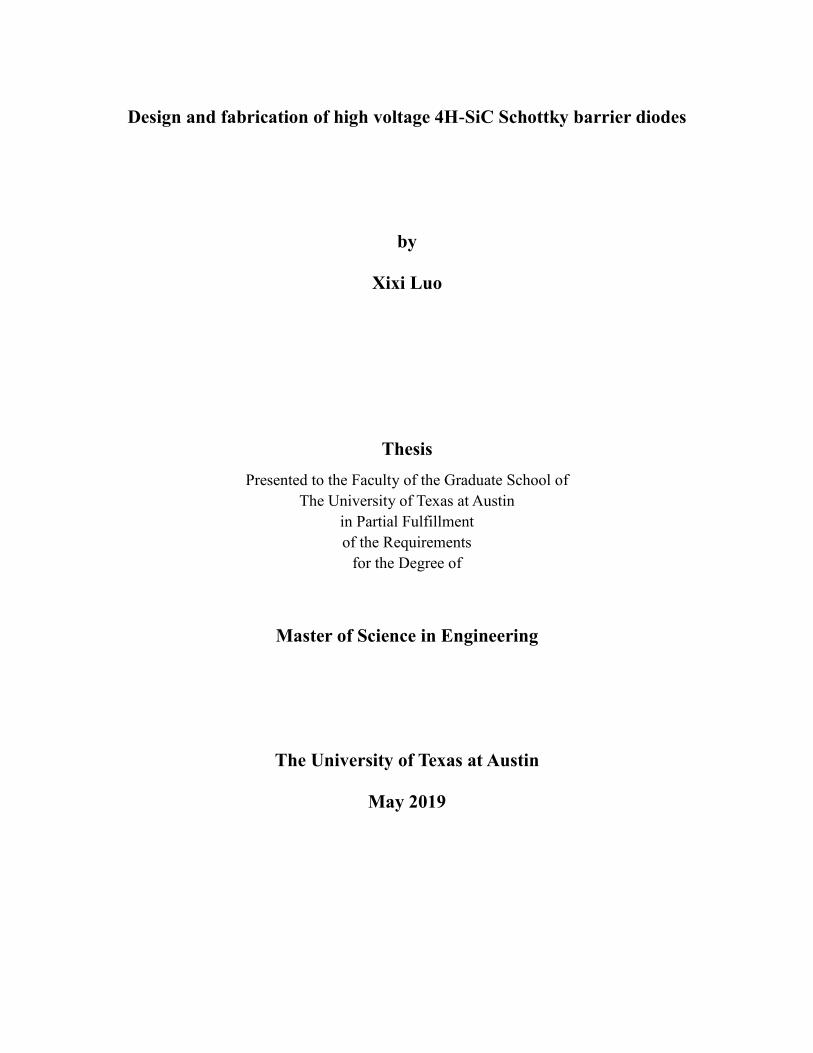
Figure 24. Cross-section of 4H-SiC SBD with implant and filed plate enhanced mesa etch
termination
The sidewall angle is set to be 5 and 15deg for comparison. Since the abovementioned result
shows that it is enough to have 5um half mesa width, it is therefore set to be 5um to reduce memory
usage. The trench depth is set to be 7.5um, which is deeper than the epi thickness.
Since it is almost impossible to perfectly align the post-deposit contact, any small distance
between the contact edge and the trench edge would kill the design. It is thus easier to make the
contact a bit overlapping with the passivation oxide layer forming a narrow field plate. However, this
field plate cannot overlap through the whole trench sidewall. Only the very edge part can push the
crowded peak electric field location from the edge of the SiC mesa into the passivated oxide region.
(a)
Figure 25.

25
(b)
Figure 25. (a) Overall (b) edge Electric field distribution of SBD with field plate and implant
enhanced mesa etch termination when ImplDop=1E16cm-3 mesa=5um, sidewall angle=15deg, trench
depth=7.5um
Since the crowded peak electric field is located in passivation layer, which has much smaller
dielectric constant than SiC, it can support much larger electric field while keeping the maximum
electric filed in SiC under critical electric field to sustain a larger breakdown voltage. Therefore, as
shown in the breakdown simulation results, the mesa etch termination with field plate and implant
enhancement is able to maintain a nearly 100% ideal breakdown voltage. This happens even at
un-optimized implant doping concentration and a sidewall angle not as small as expected. Thus,
fabrication difficulties could be largely addressed, and it is much easier to conduct even under limited
fabrication capabilities. Also, since the mesa etch termination only has couple of micrometers in width,
any structure beyond the trench edge would not influence the device on mesa. This structure would
largely reduce the size of the device, making a good isolation and largely extended the effective
implant dose window.

26
Figure 26. Breakdown voltage of 4H-SiC SBD with implant and field plate enhancement mesa
etch edge termination
However, the depth of SiC deep etch is still a challenge in device fabrication. With the oxide
thickness, the overlap width and the implant depth can still be further optimized, the finished
simulation strongly supports the advantages of the mesa etch edge termination structure. Since this
structure is very likely to be able to be achieve under the facility capability of the MRC cleanroom at
University of Texas at Austin, the next step is to fabricate and verify the simulation that has been
obtained.
2. 2. SiC Super-junction JBS diode
2.1. SiC super-junction JBS diode under punch through depletion model
Besides edge termination, similar concept of deep trench etch with side wall implant can also be
a novel type of super junction JBS diode which have combinational effect of both super junction and
JBS.
In conventional JBS diode, there are two key design elements: heavily doped p+ implant region
and small distance between each implant region. These are to make sure that the lateral depletion
extension overlapped at the bottom of Schottky contact would pinch off the leakage current and also to
reduce the surface electric field. Usually, the implant region needs to be as heavily doped at about
1E18 and the distance between each implant region shall be as small as 1 or 2 um. Also, the width of
the Schottky region, JBS region and the implant depth would also need extra optimization to achieve
the best performance.
In conventional super junction device, on the other hand, it has different design strategies from
the JBS diode. The doping concentration of the N/P drift region needs to be perfectly charge balanced.
The distance between different opposite doped drift region do not need to as small as 1 or 2 um.
0.00
200.00
400.00
600.00
800.00
1000.00
1200.00
1400.00
1600.00
1.00E+16 1.00E+17
BV vs ImplDop
BV(5umWmesa)5deg BV(5umWmesa)15deg

27
However, in the cases of trench and implant process in build a super junction device, it is impossible
to make the trench sidewall 90deg perpendicular. That means line charge at each dx (Qn=Nd*Wn
Qp=Na*Wp) would be very difficult to balance if both N and P has uniform dopant concentrations.
This is because that all the N/P drift region are actually trapezoids rather than rectangles. Therefore,
further optimization of device structure is needed when combining JBS diode and super junction
diode.
Firstly, the same model for the termination with 6.5um 1E16 N-type epitaxial layer is used, of
which 1.3kV is the maximum ideal breakdown voltage. In order to properly represent the JBS diode,
the half mesa width is set to be 0.75, 1.0, 1.25, and 1.5 um (which means that the pitch size is 1.5, 2.0,
2.5, and 3.0 um, respectively). The sidewall angle is set to be 5 and 15 degree and the trench depth is
larger than the drift thickness (which is 7.5um in this model) according to the super junction theory.
Figure 27. Cross-section of super junction JBS diode simulation model 1
In order to understand the super junction effect in this trapezoid drift super junction structure, the
implant dopant was swept from 1E15 to 4E17. The Schottky surface electric field (at ‘A’ point in
Figure. 27) was plotted, and to be expected: smaller electric field leads to better JBS effect. Since this
structure would be repeating in the whole drift region, the specific on-state resistance was also studied.

28
Figure 28. Breakdown voltage of model1 super junction JBS diode
According to the breakdown voltage simulation, the maximum breakdown voltage for 5 deg
sidewall is 1390 V at ImplDop=4e16 when Wmesa=1.5um, and the maximum breakdown voltage for
15degree sidewall is 1390V at ImplDop=9e16 when Wmesa=1.5um. This maximum breakdown
voltage is just slightly larger than the ideal breakdown voltage, which means that the super junction
effect is not as outstanding as expected. The reason is probably because this epi layer is too lightly
doped as in a punch-through PiN condition, where the vertical electric field is more rectangle-shaped
rather than triangle-shaped. Therefore, the super junction effect, which stretches the electric field from
triangle to rectangle, is not going to be a significant effect.
Figure 29. The punch-through electric field distribution for a PiN diode [2]
0.00
200.00
400.00
600.00
800.00
1000.00
1200.00
1400.00
1600.00
1.00E+15 1.00E+16 1.00E+17 1.00E+18
BV vs ImplDop
BV(0.75umWmesa)5deg BV(0.75umWmesa)15deg
BV(1umWmesa)5deg BV(1umWmesa)15deg
BV(1.25umWmesa)5deg BV(1.25umWmesa)15deg
BV(1.5umWmesa)5deg BV(1.5umWmesa)15deg

29
On the other hand, there are different optimal p doping concentrations for different trench
sidewall angles. And larger sidewall angles correspond to smaller dose windows.
Normally, a power semiconductor device would not be working under breakdown voltage but
could be working at voltages a bit smaller than the breakdown voltage as a part of the high voltage
power electronic system. Therefore, the Schottky surface electric field at ‘A’ point needs to be plotted
under the same voltage bias to predict the reverse leakage current. In the case of voltage bias equals to
1200V, the Schottky surface electric field for devices with breakdown voltage larger than 1200V can
be plotted as (Figure 30):
(a)
(b)
Figure 30. Schottky region surface electric field with trench sidewall angle of (a) 5degree and
(b)15degree under 1200V reverse bias.
0.000E+00
5.000E+05
1.000E+06
1.500E+06
2.000E+06
2.500E+06
3.000E+06
1.00E+15 1.00E+16 1.00E+17
1200V surface Efield @5deg
Electric Field(V/cm)5deg0.75um Electric Field(V/cm)5deg1um
Electric Field(V/cm)5deg1.25um Electric Field(V/cm)5deg1.5um
0
500000
1000000
1500000
2000000
2500000
1.00E+16 1.00E+17 1.00E+18
1200V surface Efield @15deg
Electric Field(V/cm)15deg0.75um Electric Field(V/cm)15deg1um
Electric Field(V/cm)15deg1.25um Electric Field(V/cm)15deg1.5um

30
Usually, the critical electric field for 4H-SiC is about 2.2~2.8MV/cm for 1E16 doped drift region,
which means the SBD would be likely to breakdown when the surface electric field approaches to this
value. However, if applying a such high reverse voltage upon the Schottky barrier, the band bending at
the metal semiconductor contact interface would very likely causes a large tunneling leakage current,
which would then become a large power loss.
The surface electric field simulation results show that the introduction of P implant trench
sidewall would significantly degrade the surface electric field. Heavier doped implant region leads to
reduced surface electric field. For optimal implant doping concentration corresponding with
breakdown voltage (for 5degree sidewall BV=1390V at ImplDop=4e16 when Wmesa=1.5um, and for
15degree sidewall BV=1390V at ImplDop=9e16 when Wmesa=1.5um), the surface electric field
would be Em=1.558MV/cm at 5 deg and Em=1.364MV/cm. Comparing to the 2.2~2.8MV/cm critical
electric field, this is about 40% reduction. However, in most of the reported JBS diode research, the
surface electric field is believed to be reduced to close to 0, which means that the model 1 super
junction JBS diode is not expected to have very good leakage characteristics but would still have the
potential to reduce the leakage.
The mesa width seems to be making no different in JBS effect, which is a bit unexpected. This
may be because that the punch trough structure has relatively lightly doped drift region. Thus, the
lateral depletion region spreads wider and a mesa width of 3um is already enough to be fully depleted.
The on-state resistance is also simulated and derived from the forward IV differential resistance
as shown in Figure 31:
(a)
Figure 31.
0.00E+00
1.00E-02
2.00E-02
3.00E-02
4.00E-02
5.00E-02
6.00E-02
1.00E+15 1.00E+16 1.00E+17 1.00E+18
Ron-sp vs ImplDop
Ron(0.75umWmesa)5deg
Ron(0.75umWmesa)15deg

31
(b)
(c)
(d)
Figure 31. Specific on-state resistance of the Model1 super junction JBS diode
A simply Schottky diode without any JBS structure is also simulated as a reference, and a
0.00E+00
5.00E-04
1.00E-03
1.50E-03
2.00E-03
2.50E-03
3.00E-03
3.50E-03
1.00E+15 1.00E+16 1.00E+17 1.00E+18
Ron-sp vs ImplDop
Ron(1umWmesa)5deg
Ron(1umWmesa)15deg
0.00E+00
5.00E-04
1.00E-03
1.50E-03
2.00E-03
2.50E-03
1.00E+15 1.00E+16 1.00E+17 1.00E+18
Ron-sp vs ImplDop
Ron(1.25umWmesa)5deg
Ron(1.25umWmesa)15deg
0.00E+00
5.00E-04
1.00E-03
1.50E-03
2.00E-03
1.00E+15 1.00E+16 1.00E+17 1.00E+18
Ron-sp vs ImplDop
Ron(1.5umWmesa)5deg
Ron(1.5umWmesa)15deg

32
specific on-state resistance of 1.05mΩ*cm2 is obtained. The on-state specific resistance simulation
results therefore show that the heavily doped JBS structure would increase the on-resistance. Small
pitch size and small the sidewall angles will cause large on-resistance.
2.2. SiC super-junction JBS diode under linear field depletion model
In order to get a good super junction effect, the doping concentration and the thickness of the
drift epi layer should be carefully designed. The drift region thickness should be as long as the
maximum depletion width and the doping concentration should be as heavy as possible based on the
application needed. For example, if the optimal drift doping concentration is 3.9E16 cm-3, the drift
region thickness should be 4um, which equals to the depletion width when the surface electric field
equals to the critical electric field (Em=Ec). These are illustrated in Figure32:
Figure 32. The linear field depletion electric field and potential distribution for a PiN diode
Therefore, the super junction JBS diode model with linear field depletion region can be simulated
using the model shown in Figure 33:
Figure 33. Cross-section of super junction JBS diode simulation model 2
33
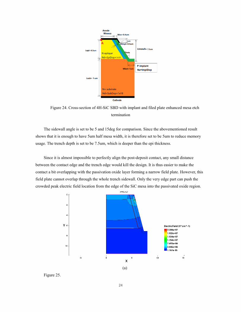
With the doping and epi thickness shown above, the ideal maximum breakdown voltage should
be: BV =1
2𝐸𝑐𝑊𝐷. If it is assumed to be 3.9E16 doped 4um epi, ideal breakdown voltage should be
700V, if the critical electric field is 3.5MV/cm for the 3.9E16 doped N type 4H-SiC (according to
Figure 9). The TCAD simulation of simple Schottky diode shows breakdown voltage as 650V.
Similarly, the mesa width is set to be 0.75, 1.0, 1.25, 1.5 and 1.75um, implant doping sweeping
range is set to be from 1E16 to 4E17. The sidewall angle is set to be 0, 5, 15, 25 deg, and the
breakdown voltage simulation is shown in Figure 34:
(a)
(b)
Figure 34.
0.00
100.00
200.00
300.00
400.00
500.00
600.00
700.00
800.00
900.00
1000.00
1.00E+16 1.00E+17
BV vs ImplDop
BV(0.75umWmesa)0deg BV(0.75umWmesa)5deg
BV(0.75umWmesa)15deg BV(0.75umWmesa)25deg
0.00100.00200.00300.00400.00500.00600.00700.00800.00900.00
1000.00
1.00E+16 1.00E+17
BV vs ImplDop
BV(1umWmesa)0deg BV(1umWmesa)5deg
BV(1umWmesa)15deg BV(1umWmesa)25deg

34
(c)
(d)
(e)
Figure 34.
0.00
200.00
400.00
600.00
800.00
1000.00
1.00E+16 1.00E+17
BV vs ImplDop
BV(1.25umWmesa)0deg BV(1.25umWmesa)5deg
BV(1.25umWmesa)15deg BV(1.25umWmesa)25deg
0.00
200.00
400.00
600.00
800.00
1000.00
1.00E+16 1.00E+17
BV vs ImplDop
BV(1.5umWmesa)0deg BV(1.5umWmesa)5deg
BV(1.5umWmesa)15deg BV(1.5umWmesa)25deg
0.00
200.00
400.00
600.00
800.00
1000.00
1.00E+16 1.00E+17
BV vs ImplDop
BV(1.75umWmesa)0deg BV(1.75umWmesa)5deg
BV(1.75umWmesa)15deg BV(1.75umWmesa)25deg

35
(f)
Figure 34. The breakdown voltage distribution along Implant doping when mesa width equals to
(a) 0.75um, (b) 1.0um (c) 1.25um, (d) 1.5um, (e) 1.75um, and (f) all above.
The maximum breakdown voltages of all the mesa width and sidewall angles are about 900V,
which is about 1.5 times the ideal parallel abrupt junction breakdown voltage. For different
combination of mesa widths and sidewall angles, there are different optimal implant doping
concentrations, which could find explanations in mathematical dynamic charge balance with further
analysis. The dose window is relatively small, but if the trench sidewall, it is believed to be able to get
a larger does window.
0.00
100.00
200.00
300.00
400.00
500.00
600.00
700.00
800.00
900.00
1000.00
1.00E+16 1.00E+17
BV vs ImplDop
BV(0.75umWmesa)0deg BV(0.75umWmesa)5deg
BV(0.75umWmesa)15deg BV(0.75umWmesa)25deg
BV(1umWmesa)0deg BV(1umWmesa)5deg
BV(1umWmesa)15deg BV(1umWmesa)25deg
BV(1.25umWmesa)0deg BV(1.25umWmesa)5deg
BV(1.25umWmesa)15deg BV(1.25umWmesa)25deg
BV(1.5umWmesa)0deg BV(1.5umWmesa)5deg
BV(1.5umWmesa)15deg BV(1.5umWmesa)25deg
BV(1.75umWmesa)0deg BV(1.75umWmesa)5deg
BV(1.75umWmesa)15deg BV(1.75umWmesa)25deg

36
Optimal implant doping concentrations are selected in JBS effect simulation with breakdown
voltage larger than 600V. ‘A’ points in surface electric field are derived and plotted in Figure 35.
(a)
(b)
Figure 35.
0.00
0.50
1.00
1.50
2.00
2.50
3.00
1.00E+16 1.00E+17
600V EF vs ImplDop @0deg
Electric Field(MV/cm)0deg0.75um Electric Field(MV/cm)0deg1um
Electric Field(MV/cm)0deg1.25um Electric Field(MV/cm)0deg1.5um
Electric Field(MV/cm)0deg1.75um
0.00
0.50
1.00
1.50
2.00
2.50
3.00
1.00E+16 1.00E+17
600V EF vs ImplDop @5deg
Electric Field(MV/cm)5deg0.75um Electric Field(MV/cm)5deg1um
Electric Field(MV/cm)5deg1.25um Electric Field(MV/cm)5deg1.5um
Electric Field(MV/cm)5deg1.75um

37
(c)
(d)
Figure 35. 600V reverse bias Schottky region surface electric field when the sidewall angle is set
to be (a) 0degree, (b) 5degree, (c) 15degree and (d) 15degree.
It is shown that small sidewall angles lead to small the surface electric fields. Also, heavier
0
0.5
1
1.5
2
2.5
3
4.00E+16
600V EF vs ImplDop @15deg
Electric Field(MV/cm)15deg0.75um Electric Field(MV/cm)15deg1um
Electric Field(MV/cm)15deg1.25um Electric Field(MV/cm)15deg1.5um
Electric Field(MV/cm)15deg1.75um
0
0.5
1
1.5
2
2.5
3
9.00E+16
600V EF vs ImplDop @25deg
Electric Field(MV/cm)25deg0.75um Electric Field(MV/cm)25deg1um
Electric Field(MV/cm)25deg1.25um Electric Field(MV/cm)25deg1.5um
Electric Field(MV/cm)25deg1.75um

38
implants are corresponded with smaller surface electric fields. These results are expected as
predictions from the JBS theory model.
Therefore, the tradeoff of super junction and JBS effect can be concluded as:
Figure 36. Tradeoff relationship between super junction effect and JBS effect in super junction
JBS diode.
0.00
0.50
1.00
1.50
2.00
2.50
3.00
500.00 600.00 700.00 800.00 900.00 1000.00
600V surface E-Field (MV/cm) vs BV
(V)
0.75um0deg
0.75um5deg
0.75um15deg
0.75um25deg
1um0deg
1um5deg
1um15deg
1um25deg
1.25um0deg
1.25um5deg
1.25um15deg
1.25um25deg
1.5um0deg
1.5um5deg
1.5um15deg
1.5um25deg
1.75um0deg
1.75um5deg
1.75um15deg
1.75um25deg

39
According to Figure. 36, the optimal super junction JBS tradeoff with BV=867.9V and surface
electric field=0.82MV/cm is achieved at Wmesa=0.75um, theta=25deg and ImplDop=2E17cm-3.
Although it is not as perfect as simple super junction or simple JBS diode, it is still a decent
improvement when comparing with the critical electric field of 3.5MV/cm and the maximum super
junction breakdown voltage of 900V.
Based on the analysis above, the large side wall angle would act as a compensate structure for
JBS needing highly doped top region and the super junction needing lightly doped bottom part of the
implant region. Unexpectedly, these would make an improvement rather than a downgrading on the
etched trench super junction JBS diode. However, to achieve such a small mesa width of 0.75um
(whole pitch size 1.5um) and to keep a deep etch trench at same time would be very difficult in terms
of fabrication. And the forward current density may also be limited since there is only a small part of
device would serve as Schottky region while other part would be etched away.
Lastly, as the abovementioned conclusions are derived from simulation results and may become
impractical in more complicated real devices, further fabrication verifications are needed to optimize
the existing model of device structure.

40
Chapter 4 Fabrication
1. Metal deposition
Two sets of 4H-SiC SBDs without edge termination structure are fabricated to verify the
simulation result. Ni is used as the top Schottky anode contact and also the bottom Ohmic cathode
contact metal, and is deposited with the e-beam evaporation system located at microelectronics
research center.
A shadow mask with arrays of 600um diameter circular pattern was used to define the 600um
4H-SiC SBD’s anode Schottky contact. Dozens of devices are characterized as shown in the table
below (Table 2).
Figure 37. The microscope image of the top Schottky contact
Table 2. Thickness of the Schottky contact and the Ohmic contact
Contact name Ni thickness (nm) Anneal condition
Chip1&2 Anode Schottky 200 1min 450
Cathode Ohmic 100 2min 900
Chip3&4 Anode Schottky 400 None
Cathode Ohmic 100 None
The work function of Ni is about 5.15 eV, making it a good candidate for high Schottky barrier
height Schottky contact but may not be a good option for Ohmic contact.

41
2. Reactive-ion etching
Plasma enhanced RIE is also conducted on the Chip2&3 with the Schottky metal as hard mask
and SBD with or without edge trench are compared. Since the Schottky metal deposition has its limit
thickness due to the mask usage, it limits the etch depth and only forms a shallow trench rather than
the deep trench etched through the whole epi layer as desired.
The RIE recipe and the process results are concluded in Table 3:
Table 3. RIE conditions for Chip2&3
Chip2&3
RIE recipe
Duration 12min
Gas Flow 50sccm SF6
DC Power 150V
Pressure 200mTorr
Chip2&3
RIE result
Etched Depth 0.69um
Selectivity SiC/Ni = 4.2/1
Etch Rate 57.5nm/min
When inspecting the etched surface, it is always noticed that there would be some brown
by-product produced after the etch process. This brown by-product is inactive and unsolvable and
remained on the surface even with solvent (H2O2, acetone, methanol or IPA) and acid (H3SO4 or HF)
clean. These indicate that the brown by-product is very inactive and stable.
Figure38. Brown by-product leftover after 4H-SiC RIE process

42
In order to identify this brown, etch by-product, XRD scan on the etched sample is conducted
and the crystal phases are identified based on XRD diffraction spectrum. The XRD results indicate
that this brown by-product belongs to carbon.
Figure 39. XRD diffraction Spectrum identification of the Etched sample
Table 4. Identified pattern list
Visible Ref. Code Score Compound
Name
Displacemen
t [°2Th.]
Scale Factor Chemical
Formula
* 00-012-0212 47 Carbon 0.000 1.000 C
* 00-005-0625 17 Carbon 0.000 0.176 C
XRD shows that this etch by-product may be some kind of defective graphite. Thus, it is very
likely to be removed by heating to a higher temperature under air. More characterizations will be
conducted in future studies.
Position [°2Theta] (Copper (Cu))
20 25 30
Counts
0
100
200
300
400 031919-Contanimates on SiC 20 to 34_Theta_2-Theta

43
Chapter 5 Device characterization
1. Forward I-V
4H-SiC SBD are tested after metal deposition and shallow trench etch. Keithley 2651A High
Current Power Source Meter system was used to determine forward characteristics used as stimuli
giving IV characteristics of all the four chips of 4H-SiC Schottky Barrier Diodes (SBDs). The features
of the four different chips are summarized in Table 5:
Table 5. Device features of the four different SBD chips
Thickness
Chip1
Schottky Anode 200nm
Ohmic Cathode 100nm
Chip2 Schottky Anode 36nm
Ohmic Cathode 100nm
Edge Trench Depth 0.69um
Chip3 Schottky Anode 236nm
Ohmic Cathode 100nm
Edge Trench Depth 0.69um
Chip4 Schottky Anode 400nm
Ohmic Cathode 100nm
The probe station has a 3.87 Ω series parasitic build-in resistance, which needs to be calibrated
while calculating the on-state resistance. The Schottky barrier height can be indicated by the turn-on
voltage of the diodes. Since there are about 50 devices on one chip, multiple tests are done and
average and smallest on-state resistances are studied.
(a)
Figure 40.
-0.01
0.04
0.09
0.14
0 0.5 1 1.5 2 2.5
Forward current vs Voltage
I(A)101 I(A)111 I(A)112 I(A)113
I(A)118 I(A)123 I(A)126 I(A)127
I(A)128 I(A)129
44
(b)
(c)
(d)
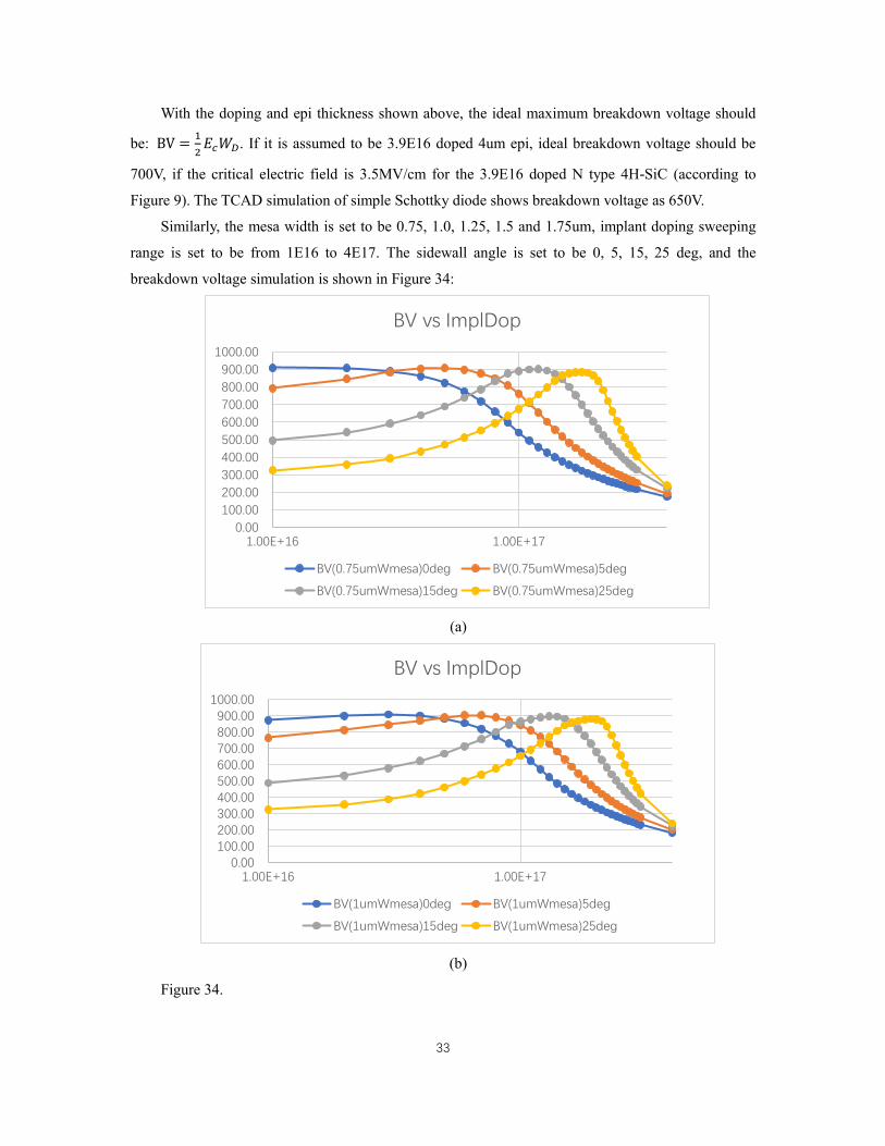
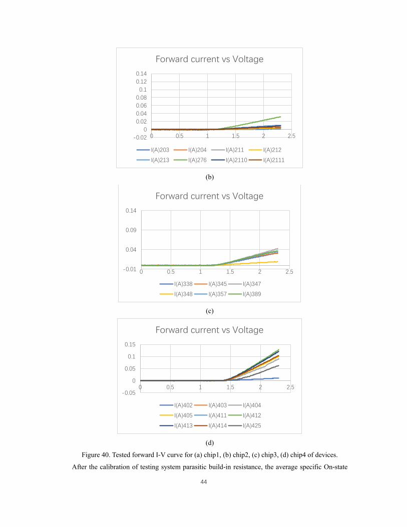
Figure 40. Tested forward I-V curve for (a) chip1, (b) chip2, (c) chip3, (d) chip4 of devices.
After the calibration of testing system parasitic build-in resistance, the average specific On-state
-0.02
0
0.02
0.04
0.06
0.08
0.1
0.12
0.14
0 0.5 1 1.5 2 2.5
Forward current vs Voltage
I(A)203 I(A)204 I(A)211 I(A)212
I(A)213 I(A)276 I(A)2110 I(A)2111
-0.01
0.04
0.09
0.14
0 0.5 1 1.5 2 2.5
Forward current vs Voltage
I(A)338 I(A)345 I(A)347
I(A)348 I(A)357 I(A)389
-0.05
0
0.05
0.1
0.15
0 0.5 1 1.5 2 2.5
Forward current vs Voltage
I(A)402 I(A)403 I(A)404
I(A)405 I(A)411 I(A)412
I(A)413 I(A)414 I(A)425

45
resistance and the minimal specific on-state resistance are calculated and summarized in Table 6:
Table 6. Forward characteristics of SBDs
Knee Voltage (V) Average Ron-sp (mΩ*cm2) Minimal Ron-sp (mΩ*cm2)
Chip1 1.23 74.3 15.8
Chip2 1.11 624.0 88.4
Chip3 1.24 101.3 54.6
Chip4 1.36 42.6 7.9
It is expected that the high temperature would reduce the Schottky Barrier height and would show
as a smaller knee voltage between Chip1&4. However, the RIE process on Chip2&3 is actually also
etching the Schottky metal, reducing the thickness and leads to a smaller knee voltage in these devices.
This indicates that the thickness of Schottky contact may have a very high connection with Schottky
barrier height and a thinner Schottky metal will likely lead to a smaller knee voltage, hence a smaller
barrier height.
On the other hand, a thicker Schottky metal corresponds with a smaller specific on resistance,
while the high temperature annealing makes no difference with respect to on-state resistance. The
significant increase on the resistance after etching is probably due to the etch induced defects on the
surface of Schottky metal, which would make the metal rough and un-continuous and significantly
reduce the quality of the contact.
The smallest on-state resistance is much larger than the calculated ideal device ideal resistance
(1.05 mΩ*cm2), which may be because of the high contact resistance. Therefore, it would need further
optimization to achieve a good contact on 4H-SiC.
To summarize, the testing results are not as expected. There might be some operational mistakes
that need to be double-checked.
2. Reverse I-V
Keithley 2657A High Voltage Power Source Meter system was used to determine reverse
characteristics as stimuli giving reverse IV curves of all the four chips of 4H-SiC SBDs. For SBD,
which has only one kind of major carrier, any avalanche breakdown might cause severe damage on the
device lattice. Therefore, smaller current compliance is set for larger breakdown voltage devices to
better protect the device.

46
At least 10 devices are tested on each chip, and average breakdown voltage and maximum
breakdown voltage are calculated.
(a)
(b)
(c)
Figure 41.
-0.000010
0.000010.000020.000030.000040.000050.00006
0 100 200 300 400 500 600
Reverse Current vs Voltage
I(A)112 I(A)116 I(A)117 I(A)122 I(A)123
I(A)124 I(A)126 I(A)128 I(A)129
-0.00001
0
0.00001
0.00002
0.00003
0.00004
0 100 200 300 400 500
Reverse current vs Voltage
I(A)201 I(A)204 I(A)205 I(A)211
I(A)213 I(A)214 I(A)215 I(A)216
I(A)217 I(A)219 I(A)276
-0.000002
0
0.000002
0.000004
0.000006
0.000008
0.00001
0.000012
0 50 100 150 200 250 300 350
Reverse current vs Voltage
I(A)384 I(A)386 I(A)387
I(A)388 I(A)3105 I(A)3106

47
(d)
Figure 41. Tested Reverse I-V curve for (a) chip1, (b) chip2, (c) chip3, (d) chip4 of devices.
Surprisingly, the breakdown voltage measurements exhibit almost the opposite results as predicted
from the simulation results: the etched device has smaller breakdown voltage and the un-etched
sample has unexpectedly larger breakdown voltage. The leakage current is relatively small. This is a
desirable result and it indicates the Schottky barrier tunneling effect is not as critical as I first believed
it to be.
Table 7. Reverse characteristics of SBDs:
Chip1 Average Breakdown Voltage (V) 310.4
Maximum Breakdown Voltage (V) 459
Maximum Leakage Current (A) 1.19e-6 (458V)
Chip2 Average Breakdown Voltage (V) 206.2
Maximum Breakdown Voltage (V) 280.5
Maximum Leakage Current (A) 1.94e-6 (277V)
Chip3 Average Breakdown Voltage (V) 233.1
Maximum Breakdown Voltage (V) 246.5
Maximum Leakage Current (A) 1.3e-6 (244V)
Chip4 Average Breakdown Voltage (V) 508.9
Maximum Breakdown Voltage (V) 692
Maximum Leakage Current (A) 5.51e-8 (691V)
The reasons for chip1&4 having unexpected large breakdown voltage would need extra
experiments and further theoretical analysis.
1E-13
1E-11
1E-09
0.0000001
0.00001
0.001
0.1 0 100 200 300 400 500 600 700 800
Reverse curretn vs Voltage
I(A)414 I(A)417 I(A)418 I(A)423
I(A)424 I(A)426 I(A)427 I(A)428
I(A)434 I(A)482 I(A)484 I(A)485

48
Chapter 6 Conclusion and future
In this thesis, simulation of 4H-SiC Schottky barrier with single floating field ring edge
termination and the novel mesa etch terminations are conducted. These present that the novel mesa
etch termination have good potential in reducing edge electric field crowd and improve the breakdown
voltage. The implant enhanced mesa etch termination has a relatively large implant does window,
rendering reduced fabrication difficulties. Moreover, the dose window can guarantee a 90% ideal
breakdown voltage or even broader combined with the edge field plate enhancement. By applying an
opposite implanted thin layer on the etch mesa sidewall surface and a narrow overlap of filed plate at
the contact edge, this new structural design of edge termination can achieve more than 90% of ideal
breakdown voltage once the implant doping just smaller than a certain value (7E16 for 5deg sidewall
and 1.2E17 for 15deg sidewall).
Simulation result shows that the super junction JBS diode design is capable to exhibit decent
tradeoff between super junction effect and JBS effect. This can maintain a 96.4% of ideal maximum
super junction breakdown voltage as well as reduce 76.6% of Schottky surface electric field at the
same time. However, the design strategies of the edge termination and the super junction JBS diode
are different from each other, which makes them not compliant with each other. Also, the dose
window of the super junction JBS diode should be much smaller than the edge termination, which
would cause more fabrication difficulties.
Plane vertical 4H-SiC Schottky diode with shallow trench are fabricated to verify the simulation
result. Ni is used as both the Schottky contact and Ohmic contact metal. A 0.69un depth RIE is
conducted on etched samples. Un-etched samples are used as comparison.
The electrical characterization is done on the fabricated Schottky diode, in which the maximum
breakdown voltage of 692V is achieved while the on-state resistance is as small as 7.9mΩ*cm2. The
on-state resistance is larger than theoretical value while the breakdown voltage is unexpectedly much
larger than simulation result. Therefore, the next step of this study should be focused on finding out
the reasons causing this unexpected larger breakdown. An optimized contact recipe will also be
investigated to reduce the on-state resistance.
The deep trench edge termination and super junction JBS structure are also verified to a
fabrication standard. These may need further design and optimizations in both the pattern layout
design and fabrication process design.

49
Appendix
TCAD commands for SDE device structure generation:
(define Lepi @Lepi@)
(define Ltrench (+ Lepi 1.0))
(define Wmesa @Wmesa@)
(define Wtrenchbot 1.0)
(define TanA @TanA@)
(define Wedge (* Ltrench TanA))
(define Wimpl 0.5)
(define Wox 0.4)
(define Wtrench (+ Wtrenchbot Wedge))
(define Wtot (+ Wmesa Wtrench))
(define Lsub 5.0)
(define Ltot (+ Lsub Lepi))
(define EpiDop @EpiDop@)
(define ImplDop @ImplDop@)
(define SubDop 1E18)
(define A @1/CosA@)
(define Wt (* Wimpl A))
(define We (+ Wmesa (+ Wedge (- (* Wox A) (* Wox TanA)))))
; =================== Outer Boundary Creation =========================
;---SiC Region
(sdegeo:create-polygon
(list
(position 0.0 0.0 0.0)
(position Wmesa 0.0 0.0)
(position (+ Wmesa Wedge) Ltrench 0.0)
(position Wtot Ltrench 0.0)
(position Wtot Ltot 0.0)
(position 0.0 Ltot 0.0)
)
"SiliconCarbide" "EpiSubRegion" )
;---SiO2 Region

50
(sdegeo:create-polygon
(list
(position Wmesa 0.0 0.0)
(position (+ Wmesa (* Wox A)) 0.0 0.0)
(position We (- Ltrench Wox) 0.0)
(position Wtot (- Ltrench Wox) 0.0)
(position Wtot Ltrench 0.0)
(position (+ Wmesa Wedge) Ltrench 0.0)
)
"SiO2" "SiO2Region" )
;---SchottkyMetal Region
(sdegeo:create-polygon
(list
(position 0.0 0.0 0.0)
(position (+ Wmesa (* Wox A)) 0.0 0.0)
(position (+ Wmesa (+ (* TanA 1.0)(* Wox A))) 1.0 0.0)
(position Wtot 1.0 0.0)
(position Wtot -0.1 0.0)
(position 0.0 -0.1 0.0)
)
"Nickle" "SchottkyMetalRegion" )
; =================== Contact Definition Placement =========================
(sdegeo:define-contact-set "top_schottky" 4.0 (color:rgb 1.0 0.0 0.0) "##")
(sdegeo:define-contact-set "bot_ohmic" 4.0 (color:rgb 1.0 0.0 0.0) "##")
(sdegeo:insert-vertex (position 1.2 0.0 0.0))
(sdegeo:set-current-contact-set "top_schottky")
(sdegeo:set-contact-boundary-edges (find-body-id (position 0.5 -0.1 0.0)))
(sdegeo:delete-region (find-body-id (position 0.5 -0.1 0.0)))
(sdegeo:define-2d-contact (find-edge-id (position 0.5 Ltot 0.0)) "bot_ohmic")
; =================== Constant and Analytical Profiles =========================
;---Definitions
(sdedr:define-constant-profile "Epi_Dop_Defn" "NitrogenActiveConcentration" EpiDop)
(sdedr:define-constant-profile "Sub_Dop_Defn" "NitrogenActiveConcentration" SubDop)
(sdedr:define-constant-profile "Impl_Dop_Defn" "AluminumActiveConcentration" ImplDop)
;---Windows

51
(sdedr:define-refeval-window "Epi_Win" "Polygon"
(list
(position 0 0 0)
(position (- Wmesa Wt) 0 0.0)
(position (+ Wmesa (- (* Lepi TanA) Wt)) Lepi 0)
(position 0 Lepi 0)
))
(sdedr:define-refeval-window "Sub_Win" "Rectangle"
(position 0 Lepi 0)
(position Wtot Ltot 0.0)
)
(sdedr:define-refeval-window "Impl_Win" "Polygon"
(list
(position (- Wmesa Wt) 0.0 0.0)
(position Wmesa 0.0 0.0)
(position (+ Wmesa (* Lepi TanA)) Lepi 0.0)
(position (+ Wmesa (- (* Lepi TanA) Wt)) Lepi 0.0)
))
;---Placement
(sdedr:define-constant-profile-placement "Epi_Place" "Epi_Dop_Defn" "Epi_Win")
(sdedr:define-constant-profile-placement "Sub_Place" "Sub_Dop_Defn" "Sub_Win")
(sdedr:define-constant-profile-placement "Impl_Place" "Impl_Dop_Defn" "Impl_Win")
; =================== Refinements =========================
;---Definitions
(sdedr:define-refinement-size "Global_Ref_Defn"
1.0 1.0 0.0
0.3 0.3 0.0 )
(sdedr:define-refinement-size "Epi_Ref_Defn"
0.5 0.5 0.0
0.1 0.1 0.0)
(sdedr:define-refinement-size "Epiedge_Ref_Defn"
0.1 0.1 0.0
0.05 0.05 0.0)
(sdedr:define-refinement-size "Trenchedge1_Ref_Defn"
0.05 0.05 0.0

52
0.01 0.01 0.0)
(sdedr:define-refinement-size "Trenchedge2_Ref_Defn"
0.05 0.05 0.0
0.01 0.01 0.0)
(sdedr:define-refinement-size "Trenchedge3_Ref_Defn"
0.05 0.05 0.0
0.01 0.01 0.0)
(sdedr:define-multibox-size "Multi_Box_Defn"
1.0 0.3 0.0
0.1 0.002 0.0
1.0 1.4 1.0)
(sdedr:define-refinement-size "Ref.SiAct"
0.2 0.2 0.0
0.01 0.005 0.0 )
;---Windows
(sdedr:define-refinement-window "Global_Win"
"Rectangle" (position 0.0 0.0 0.0) (position Wtot Ltot 0.0) )
(sdedr:define-refinement-window "Epi_Win"
"Rectangle" (position 0.0 0.0 0.0) (position Wtot Ltrench 0.0) )
(sdedr:define-refinement-window "Epiedge_Win"
"Rectangle" (position 0.0 (- Lepi 0.5) 0.0) (position Wtot (+ Lepi 0.5) 0.0) )
(sdedr:define-refinement-window "Trenchedge1_Win"
"Rectangle" (position (- Wmesa Wimpl) 0.0 0.0) (position (+ Wmesa (* 0.5 Wedge)) (* 0.5 Ltrench)
0.0) )
(sdedr:define-refinement-window "Trenchedge2_Win"
"Rectangle" (position (- (+ Wmesa (* 0.5 Wedge)) Wimpl) (* 0.5 Ltrench) 0.0) (position (+ Wmesa
Wedge) (+ Wimpl Ltrench) 0.0) )
(sdedr:define-refinement-window "Trenchedge3_Win"
"Rectangle" (position (+ Wmesa Wedge) Ltrench 0.0) (position Wtot (+ Wimpl Ltrench) 0.0) )
(sdedr:define-refinement-window "Multi_Box_Win"
"Rectangle" (position 0.0 0.0 0.0) (position Wtot 8.0 0.0) )
(sdedr:define-refinement-window "RWin.Act"
"Rectangle" (position 0.0 0.0 0.0) (position Wtot 0.5 0.0) )
;---Refinement function
(sdedr:define-refinement-function "Ref.SiAct" "DopingConcentration" "MaxTransDiff" 1)
;---Placement
(sdedr:define-refinement-placement "Global_Ref_Place" "Global_Ref_Defn" "Global_Win" )

53
(sdedr:define-refinement-placement "Epi_Ref_Place" "Epi_Ref_Defn" "Epi_Win" )
(sdedr:define-refinement-placement "Epiedge_Ref_Place" "Epiedge_Ref_Defn" "Epiedge_Win" )
(sdedr:define-refinement-placement "Trenchedge1_Ref_Place" "Trenchedge1_Ref_Defn"
"Trenchedge1_Win" )
(sdedr:define-refinement-placement "Trenchedge2_Ref_Place" "Trenchedge2_Ref_Defn"
"Trenchedge2_Win" )
(sdedr:define-refinement-placement "Trenchedge3_Ref_Place" "Trenchedge3_Ref_Defn"
"Trenchedge3_Win" )
(sdedr:define-refinement-placement "RefPlace.SiAct" "Ref.SiAct" "RWin.Act")
(sdedr:define-multibox-placement "Multi_Box_Place" "Multi_Box_Defn" "Multi_Box_Win")
;----------------------------------------------------------------------
; Build Mesh
(sde:build-mesh "snmesh" " " "n@node@_msh")
TCAD commands for SDevice device physics simulation:
File
Grid= "@tdr@"
Plot= "@tdrdat@"
Current= "@plot@"
Output= "@log@"
Parameter= "@parameter@"
Electrode
#if @<[string compare SIM "IV"] == 0>@
Name="top_schottky" Schottky Workfunction= 5.56 Voltage= 0.0
#else
Name="top_schottky" Schottky Workfunction= 5.56 Voltage= 0.0 Resist= 1e13
#endif
Name="bot_ohmic" Voltage= 0.0
Physics
#if [string compare @SIM@ "Breakdown"] == 0
Recombination (

54
SRH(DopingDependence TempDependence)
Auger
Avalanche (OkutoCrowell)
ConstantCarrierGeneration (value = 1E12)
)
#elif [string compare @SIM@ "IV"] == 0
Recombination (
SRH(DopingDependence TempDependence)
Auger
)
#endif
Aniso (
Avalanche
eMobilityFactor (Total) = 1
hMobilityFactor (Total) = 0.83
)
eBarrierTunneling "NLM"
Mobility (
DopingDependence
HighFieldSaturation
IncompleteIonization
)
IncompleteIonization
EffectiveIntrinsicDensity ( oldSlotboom NoFermi )
Temperature= 300
Plot
eDensity hDensity
eCurrent hCurrent
ElectricField
Doping
eVelocity hVelocity
BarrierTunneling
ConductionBandEnergy ValenceBandEnergy BandGap
NonLocal

55
Math
NonLocal "NLM" (
Electrode= "top_schottky"
Length= 1e-5
Digits= 3
EnergyResolution= 0.001
)
Extrapolate
ErrRef(electron)= 1
ErrRef(hole)= 1
eDrForceRefDens= 1
hDrForceRefDens= 1
ExtendedPrecision
RHSmax= 1e30
RHSmin= 1e-30
RHSFactor= 1e30
CdensityMin= 1.0e-30
Notdamped= 1000
Iterations= 25
TensorGridAniso
Solve
Poisson
Coupled(Iterations= 100 LineSearchDamping= 1e-4) Poisson Electron
Coupled(Iterations= 100 LineSearchDamping= 1e-4) Poisson Electron Hole
#if @<[string compare SIM "Breakdown"] == 0>@
NewCurrentFile= "BV_"
Quasistationary (
Initialstep= 1e-3 Increment= 1.4
Maxstep= 0.075 Minstep= 1.e-15
Goal Name="top_schottky" Voltage= -5000
) Coupled Poisson Electron Hole
#elif @<[string compare SIM "IV"] == 0>@
Quasistationary (
Initialstep= 1e-2 Increment= 1.4

56
Maxstep= 0.2 Minstep= 1.e-8
Goal Name="top_schottky" Voltage=-10
) Coupled Poisson Electron Hole
NewCurrentFile= "IV_"
Quasistationary (
Initialstep= 1e-2 Increment= 1.4
Maxstep= 0.025 Minstep= 1.e-8
Goal Name="top_schottky" Voltage= 10.0
) Coupled Poisson Electron Hole
CurrentPlot ( Time= (Range= (0.00 0.50) Intervals= 20;
Range= (0.50 0.75) Intervals= 20;
Range= (0.75 1.00) Intervals= 10))
#endif

57
References
[1]. Huang, Alex Q. "Power semiconductor devices for smart grid and renewable energy
systems." Proceedings of the IEEE105.11 (2017): 2019-2047.
[2]. Baliga, B. Jayant. Fundamentals of power semiconductor devices. Springer Science & Business
Media, 2010.
[3]. Millán, José, et al. "A survey of wide bandgap power semiconductor devices." IEEE transactions
on Power Electronics 29.5 (2014): 2155-2163.
[4]. She, Xu, et al. "Review of silicon carbide power devices and their applications." IEEE
Transactions on Industrial Electronics64.10 (2017): 8193-8205.
[5]. Kimoto, Tsunenobu. "Material science and device physics in SiC technology for high-voltage
power devices." Japanese Journal of Applied Physics 54.4 (2015): 040103.
[6]. Sung, Woongje, et al. "A new edge termination technique for high-voltage devices in 4H-SiC–
multiple-floating-zone junction termination extension." IEEE Electron Device Letters 32.7 (2011):
880-882.
[7]. Li, X., et al. "Multistep junction termination extension for SiC power devices." Electronics
Letters 37.6 (2001): 392-393.
[8]. Hiyoshi, Toru, et al. "Simulation and experimental study on the junction termination structure for
high-voltage 4H-SiC PiN diodes." IEEE Transactions on electron devices 55.8 (2008): 1841-1846.
[9]. Zhao, Jian H., Petre Alexandrov, and X. Li. "Demonstration of the first 10-kV 4H-SiC Schottky
barrier diodes." IEEE Electron Device Letters 24.6 (2003): 402-404.
[10]. Ghandi, Reza, et al. "High-voltage 4H-SiC PiN diodes with etched junction termination
extension." IEEE Electron Device Letters 30.11 (2009): 1170-1172.
[11]. Jiang, Jheng-Yi, et al. "Experimental study of counter-doped junction termination extension for
4H–SiC power devices." IEEE Electron Device Letters 36.7 (2015): 699-701.
[12]. Sung, Woongje, Alex Q. Huang, and B. Jayant Baliga. "Bevel junction termination extension—A
new edge termination technique for 4H-SiC high-voltage devices." IEEE Electron Device Letters 36.6
(2015): 594-596.
[13]. Shenoy, Praveen M., Anup Bhalla, and Gary M. Dolny. "Analysis of the effect of charge
imbalance on the static and dynamic characteristics of the super junction MOSFET." 11th
International Symposium on Power Semiconductor Devices and ICs. ISPSD'99 Proceedings (Cat. No.
99CH36312). IEEE, 1999.
[14]. Udrea, Florin, Gerald Deboy, and Tatsuhiko Fujihira. "Superjunction power devices, history,
development, and future prospects." IEEE Transactions on Electron Devices 64.3 (2017): 713-727.
[15]. Fujihira, Tatsuhiko. "Theory of semiconductor superjunction devices." Japanese journal of
applied physics 36.10R (1997): 6254.
[16]. Ludikhuize, Adriaan W. "A review of RESURF technology." 12th International Symposium on
Power Semiconductor Devices & ICs. Proceedings (Cat. No. 00CH37094). IEEE, 2000.
[17]. Udrea, F., A. Popescu, and W. Milne. "The 3D RESURF junction." 1998 International
Semiconductor Conference. CAS'98 Proceedings (Cat. No. 98TH8351). Vol. 1. IEEE, 1998.

58
[18]. Singh, Ranbir, et al. "High-power 4H-SiC JBS rectifiers." IEEE Transactions on Electron
Devices 49.11 (2002): 2054-2063.
[19]. Di Benedetto, Luigi, et al. "Analytical model and design of 4H-SiC planar and trenched JBS
diodes." IEEE Transactions on Electron Devices 63.6 (2016): 2474-2481.
[20]. Tanimoto, Satoshi, et al. "Single contact-material MESFETs on 4H-SiC." Materials Science
Forum. Vol. 457. Trans Tech Publications, 2004.
[21]. Dowling, Karen M., Elliot H. Ransom, and Debbie G. Senesky. "Profile evolution of high aspect
ratio silicon carbide trenches by inductive coupled plasma etching." Journal of
Microelectromechanical Systems 26.1 (2017): 135-142.
[22]. Jiang, Liudi, et al. "Inductively coupled plasma etching of SiC in SF 6/O 2 and etch-induced
surface chemical bonding modifications." Journal of Applied Physics 93.3 (2003): 1376-1383.