Copyright by Tushar Sharma 2010
60
Copyright by Tushar Sharma 2010
Transcript of Copyright by Tushar Sharma 2010

Copyright
by
Tushar Sharma
2010

The Thesis Committee for Tushar Sharma
Certifies that this is the approved version of the following thesis :
THIN FILM NANOPOROUS SILICA AND GRAPHENE BASED
BIOFUEL CELLS (iBFCs) FOR LOW-POWER IMPLANTABLE
MEDICAL DEVICE APPLICATIONS
APPROVED BY
SUPERVISING COMMITTEE:
Xiaojing Zhang
Thomas E. Milner
Supervisor:

THIN FILM NANOPOROUS SILICA AND GRAPHENE BASED
BIOFUEL CELLS (iBFCs) FOR LOW-POWER IMPLANTABLE
MEDICAL DEVICE APPLICATIONS
by
Tushar Sharma, B. Tech.
Thesis
Presented to the Faculty of the Graduate School of
The University of Texas at Austin
in Partial Fulfillment
of the Requirements
for the Degree of
Master of Science in Engineering
The University of Texas at Austin
August, 2010

Dedication
I whole-heartedly dedicate my work to my beloved parents, who have been extremely
supportive of me in all my endeavors.

v
Acknowledgements
I would like to acknowledge my parents, UT faculty and my friends who have
been very supportive of me in pursuing my dream project at The University of Texas at
Austin. I am highly indebted to numerous faculty members, including Dr. Marc Feldman,
Dr. Thomas Milner, Dr. Mauro Ferrari, Dr. Pengyu Ren, Dr. Rodney S. Ruoff, Dr. John
Pearce, Dr. Krishnendu Roy, Dr. Allen Bard, Dr. Sanjay Banerjee, Dr. Andrew Ellington
and last but not the least, Dr. Xiaojing (John X.J.) Zhang and their respective students
who have been very helpful with generous advise, resources, and guidance. I would also
like to thank all my lab members at the Zhang Research group for their help and support.
I am also thankful to the Biomedical Engineering Department and its staff members for
all their help. Lastly, I would like to acknowledge all my lovely fellow graduate students
and friends without whom, this project could not have succeeded.
July 15, 2010
vi
Abstract
THIN FILM NANOPOROUS SILICA AND GRAPHENE BASED
BIOFUEL CELLS (iBFCs) FOR LOW-POWER IMPLANTABLE
MEDICAL DEVICE APPLICATIONS
Tushar Sharma, M.S.E.
The University of Texas at Austin, 2010
Supervisor: Xiaojing Zhang
This thesis describes the fabrication and characterization of an inorganic catalyst based
glucose Biofuel cell using nanoporous (mesoporous) silica thin-film as a functional
membrane. The desired use of nanoporous silica based biofuel cell is for a blood vessel
implantable device. Blood vessel implantable Biofuel Cells (iBFCs) are subjected to
higher glucose concentrations and blood flow rates. However, reduction in the implant
thickness is critical for the intra-vascular implantable Biofuel cells. Platinum thin-film
(thickness: 25 nm) deposited on Silicon substrate (500 µm) served as the anode while
Graphene pressed on Stainless steel mesh (175 µm) was used as the cathode. Control
experiments involved the use of surfactant-coated polypropylene membrane (50 µm) and
Activated Carbon (198 µm) electrodes. Preliminary results show that nanoporous silica
thin film (270 nm) is capable of replacing the conventional polymer based membranes
with an increased power density output of as high as 10 µW/cm2 under physiological
conditions. in-vitro (5 µW/cm2) and in-vivo (10 µW/cm
2) experiments demonstrate the
potential of ultra-thin iBFCs towards powering future medical implants.
vii
TABLE OF CONTENTS
LIST OF TABLES…………………………………………………………………….. ix
LIST OF FIGURES…………………………………………………………………… x
1. INTRODUCTION 1
1.1Background…………………………………………………………………. 3
1.2 BioFuel Cells………………………………………………………………. 4
1.2.1 Site Of Implant…………………………………………………… 7
1.2.2 Anode……………………………………………………………. 8
1.2.3 Cathode………………………………………………………….. 9
1.2.4 Membrane………………………………………………………... 9
1.3 Current Scenario…………………………………………………………… 10
2. EXPERIMENTAL SECTION 14
2.1 Electrode Fabrication………………………………………………………. 14
2.2 Preparation Of Thin-Film Nanoporous Silica On Anodes………………… 14
2.3 Characterization Techniques For Nanoporous Silica……………………… 16
2.4 Assembly of in-vitro iBFC………………………………………………… 17
2.5 Electrochemical Testing…………………………………………………… 18
2.6 Assembly and Implantation of in-vivo iBFC……………………………… 21
3. RESULTS 23
3.1 Nanoporous Silica………………………………………………………….. 23
3.2 Biofuel Cell Performance………………………………………………….. 27
3.2.1 Stainless Steel as Current Collector……………………………… 27
3.2.2 Performance at 0.42% glucose…………………………………… 28
3.2.3 Performance at 0.1% glucose……………………………………. 30
3.2.4 Comparison of Performance……………………………………... 32
3.2.5 Comparison of Performance with Other Reported Literature
Results…………………………………………………………………. 33
3.2.6 Performance of in-vivo iBFC……………………………………..34

viii
4. DISCUSSIONS 36
5. CONCLUSIONS 39
6. REFERENCES 40
VITA 49
ix
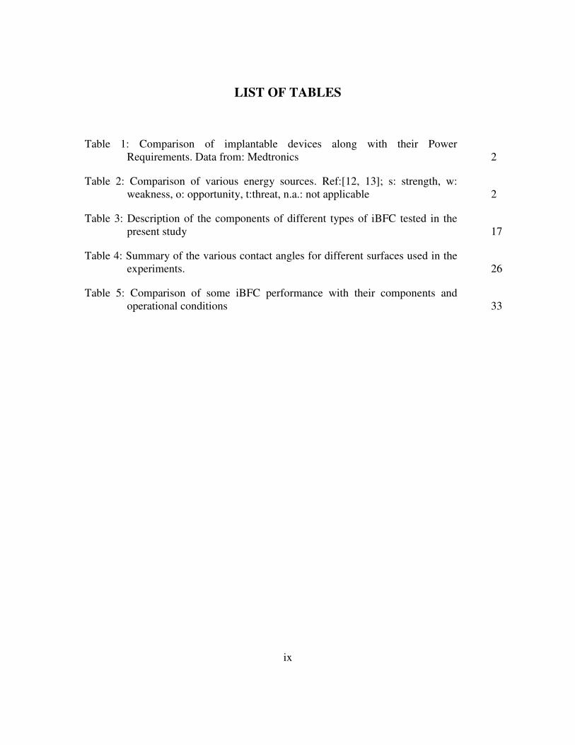
LIST OF TABLES
Table 1: Comparison of implantable devices along with their Power
Requirements. Data from: Medtronics 2
Table 2: Comparison of various energy sources. Ref:[12, 13]; s: strength, w:
weakness, o: opportunity, t:threat, n.a.: not applicable 2
Table 3: Description of the components of different types of iBFC tested in the
present study 17
Table 4: Summary of the various contact angles for different surfaces used in the
experiments. 26
Table 5: Comparison of some iBFC performance with their components and
operational conditions 33
x
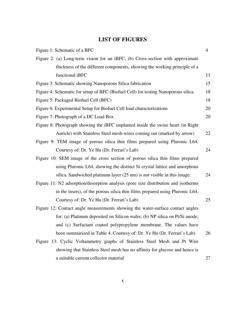
LIST OF FIGURES
Figure 1: Schematic of a BFC 4
Figure 2: (a) Long-term vision for an iBFC, (b) Cross-section with approximate
thickness of the different components, showing the working principle of a
functional iBFC 11
Figure 3: Schematic showing Nanoporous Silica fabrication 15
Figure 4: Schematic for setup of BFC (Biofuel Cell) for testing Nanoporous silica 18
Figure 5: Packaged Biofuel Cell (BFC) 18
Figure 6: Experimental Setup for Biofuel Cell load characterizations 20
Figure 7: Photograph of a DC Load Box 20
Figure 8: Photograph showing the iBFC implanted inside the swine heart (in Right
Auricle) with Stainless Steel mesh-wires coming out (marked by arrow) 22
Figure 9: TEM image of porous silica thin films prepared using Pluronic L64.
Courtesy of: Dr. Ye Hu (Dr. Ferrari’s Lab) 24
Figure 10: SEM image of the cross section of porous silica thin films prepared
using Pluronic L64, showing the distinct Si crystal lattice and amorphous
silica. Sandwiched platinum layer (25 nm) is not visible in this image. 24
Figure 11: N2 adsorption/desorption analysis (pore size distribution and isotherms
in the insets), of the porous silica thin films prepared using Pluronic L64.
Courtesy of: Dr. Ye Hu (Dr. Ferrari’s Lab) 25
Figure 12: Contact angle measurements showing the water-surface contact angles
for: (a) Platinum deposited on Silicon wafer, (b) NP silica on Pt/Si anode;
and (c) Surfactant coated polypropylene membrane. The values have
been summarized in Table 4. Courtesy of: Dr. Ye Hu (Dr. Ferrari’s Lab) 26
Figure 13: Cyclic Voltammetry graphs of Stainless Steel Mesh and Pt Wire
showing that Stainless Steel mesh has no affinity for glucose and hence is
a suitable current collector material 27
xi
Figure 14: Experimental results obtained with Polymer membrane vs. Nanoporous
Silica based BFCs: (a) Power Density Curves, and (b) Polarization
Curves 29
Figure 15: Experimental results obtained with Polymer membrane vs. Nanoporous
Silica based BFCs: (a) Power Density Curves, and (b) Polarization
Curves 31
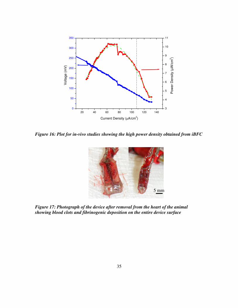
Figure 16: Plot for in-vivo studies showing the high power density obtained from
iBFC 35
Figure 17: Photograph of the device after removal from the heart of the animal
showing blood clots and fibrinogenic deposition on the entire device
surface 35
1
1. INTRODUCTION
Cardiovascular disease (CVD) is the number one killer in the US and worldwide [1]. The
increasing age of the population, the obesity epidemic, the increased occurrence of
diabetes and the increased survival of patients with diseases that lead to heart disease
further magnify this serious health problem. The most recent American Heart Association
(AHA) report paints a grim picture of the present and future of CVD [1]. Currently, over
70 million Americans suffer from CVD and the overall cost of health care in 2007 alone
exceeded 430 billion USD. Consequently, there is an upsurge in the various novel
implantable devices to diagnose, monitor, and treat cardiovascular disease [2-10]. Since
most of these implantable devices need to work on a long-duration basis ( >8 years), the
spotlight has shifted towards the development of compact, efficient and low-power
consuming implants. With the emergence of micro-electro mechanical systems (MEMS)
based implantable devices [8, 11] fabrication of low-power devices can be realized. But
for even the most low-power consuming devices, use of batteries is not considered to be a
suitable long-term solution. Batteries are considered to be bulky for MEMS based
implants and for bigger implants like artificial pacemakers, defibrillators, and insertable
cardiac monitors, batteries provide limited life-span. Currently, these batteries are
replaced on average every seven years (Table1), while the life span of the patient may be
more than 20 years, resulting in unnecessary pain and increased cost to the patient.
Further, there is a desire to piggyback newer devices such as heart failure warning

2
systems onto AICDs and pacemakers, yet the batteries used in these existing devices lack
sufficient energy to allow the addition of newer devices.
Table1: Comparison of implantable devices and their Power Requirements. Courtesy:
Medtronics
Model Description Voltage Current Battery
Capacity
Estimated Life
Reveal
DX
Insertable Cardiac Monitor
3.6 V - 0.25 Ah 3 Yrs
Maximo Single Chamber
ICD 3.2 V
9.1 µA (pacing)
0.9 Ah 9 Yrs
Vitatron Pacemaker 2.8 V 14.8 – 24.2 µA (pacing)
1.4 Ah 7-8 Yrs
Considering the disadvantages associated with existing battery technology, implantable
Biofuel Cells (iBFCs) are attracting attention. iBFCs provide superior advantages over
conventional batteries by reducing patient costs for battery replacements while
simultaneously providing ease of sterilization and biocompatibility [14, 15].
Table 2: Comparison
of various energy
sources. Ref:[12,
13]; s: strength, w:
weakness, o:
opportunity, t:threat,
n.a.: not applicable

3
Table 2 summarizes the advantages of an iBFC over other sources for energy generation.
Realization of efficient iBFCs can circumvent existing hurdles and aid the development
of next generation implantable devices and sensors [14].
1.1 Background
Implantable Biofuel Cells (iBFCs) have been a topic of interest since the 1970s [16-18].
These early efforts were motivated by the short life-time of the zinc/mercury oxide
batteries commonly used at that time. Zinc/mercury oxide batteries were used to power
cardiac pace makers, but they required frequent replacement. The power output of these
first implantable Biofuel cells in the 1970s was in the range of 40 µW, sufficient to
supply an ICD [19] (Table1). The capability of biofuel cells for powering an implantable
artificial heart was also proposed and demosntrated [14, 20]. Although the durability of
iBFCs when implanted outside the abdominal cavity exceeded 150 days [19],
biocompatibility was not fully proven. However, following the introduction of the lithium
iodine battery in 1972 [21], and the subsequent improvement of pacemaker battery
lifetime, no further development of iBFCs have been reported. The rapid progress in
autonomous, self-sufficient MEMS (micro-electro-mechanical systems) implants has
revived the research in long-term stable sources of energy for implantable devices.
Presently, very few research groups are working actively on iBFC [22, 23].

4
1.2 Biofuel Cells
In any fuel cell, electrical energy is generated by the electrochemical reaction of fuel and
oxidant at two spatially separated electrodes [16], usually separated by an insulating
membrane (Figure 1). Electrons, released upon the electro-oxidation of the fuel, travel
from the anode through an external circuit to the cathode, where the terminal electron
acceptor, usually oxygen, is reduced. The driving force of the electron flow is the
difference in electrochemical potential of the anode and cathode redox pairs. The
insulating membrane maintains electroneutrality inside the fuel cell compartments by
facilitating ion diffusion (in an ionic electrolyte) between the anode and cathode.
In general, glucose-consuming fuel cells can be divided into three main types according
to the type of catalyst that is used to enable the electrode reactions: enzymatic, microbial,
and a biotic glucose fuel cells. Enzymatic fuel cells employ enzymes such as glucose
oxidase and laccase in their isolated forms, whereas in microbial fuel cells the enzymatic
system of a whole,
electroactive micro-organism
is used. In contrast, abiotically
catalyzed fuel cells make use
of non-biological, abiotic
catalysts, e.g., noble metals or activated carbon. Over the last four decades, research in
both the development of enzymatic and microbial fuel cells has been reported [24-26].
Whereas implantable enzymatic glucose fuel cells are currently under development, the
Anode
Cathode 0.5O2+H2O+2e-→2OH
-
C6H12O6+2OH-C6H12O7+H2O+2e
-
Oxygen + Glucose
Direction of Flow
Membrane
Figure 1: Schematic of a BFC

5
limited stability of enzymes renders their application in a long-term implantable fuel cell
power supply problematic [27]. Power-supply systems based on microbial fuel cells are
not seriously considered for implantation, due to the infective nature of most known
micro-organisms and the associated risks herewith. Abiotically catalyzed fuel cells
employ mainly noble metal catalysts and are therefore considered to be advantageous
regarding their sterilizability, long-term stability, and biocompatibility [28].
Theoretically, glucose can be completely oxidized to carbon dioxide and water, releasing
24 electrons per molecule glucose [23]. The relevant fuel cell reaction and theoretical cell
voltage would be given as:
Anode: C6H12O6 + 2 OH- 6CO2 + 18 H20 + 24 e
-
Cathode: 6 O2 + 12 H2O + 24 e- 24 OH
-
Overall reaction: C6H12O6 + 6 O2 6 CO2 + 18 H2O
∆G˚= -2.87 x 10⁶ J/mol[28]; V˚= 1.24V
Where, ∆G˚ is the standard Gibbs Free Energy and V˚ is the standard Reaction Potential.
In practice, the transfer of 24 electrons per molecule of glucose has not yet been
achieved. Rao and Drake reported gluconic acid to be the only reaction product that could
be identified [28]. The oxidation of glucose to gluconic acid only yields two electrons per
molecule of glucose and the corresponding electrode reactions are given by:
6
Anode: C6H12O6 + 2 OH- C6H12O7 + H20 + 2 e
-
Cathode: 0.5 O2 + H2O + 2e- 2OH
-
Overall reaction: C6H12O6 + 0.5 O2 C6H12O7
Where,
∆G˚= -2.51 x 10⁵ J/mol[28]; V˚= 1.30V
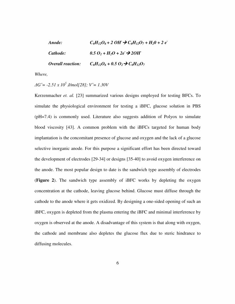
Kerzenmacher et. al. [23] summarized various designs employed for testing BFCs. To
simulate the physiological environment for testing a iBFC, glucose solution in PBS
(pH=7.4) is commonly used. Literature also suggests addition of Polyox to simulate
blood viscosity [43]. A common problem with the iBFCs targeted for human body
implantation is the concomitant presence of glucose and oxygen and the lack of a glucose
selective inorganic anode. For this purpose a significant effort has been directed toward
the development of electrodes [29-34] or designs [35-40] to avoid oxygen interference on
the anode. The most popular design to date is the sandwich type assembly of electrodes
(Figure 2). The sandwich type assembly of iBFC works by depleting the oxygen
concentration at the cathode, leaving glucose behind. Glucose must diffuse through the
cathode to the anode where it gets oxidized. By designing a one-sided opening of such an
iBFC, oxygen is depleted from the plasma entering the iBFC and minimal interference by
oxygen is observed at the anode. A disadvantage of this system is that along with oxygen,
the cathode and membrane also depletes the glucose flux due to steric hindrance to
diffusing molecules.
7
1.2.1 SITE OF IMPLANT
In principle, an iBFC can either be directly in contact with the blood stream or implanted
in tissue. The reactant supply of implantable fuel cells developed for tissue implantation
[41, 42] relies solely on diffusion. While the surrounding tissue poses an additional mass
transfer resistance, the risk of thrombi formation and blood coagulation is minimized
compared to when exposed to blood stream. The placement site for such an iBFC is
envisioned to be directly on the exterior surface of the pacemaker [29]. This site would
facilitate implantation procedures and eliminate the risk of pacemaker lead failure, which
was a common reason for pacemaker breakdown previously [19, 28].
In contrast, blood stream implantable iBFCs have been proposed [43]. The blood flow
provides a steady reactant supply that is not limited by diffusion from blood vessel walls
into the surrounding tissue. The glucose diffusion rate in the case of cylindrical electrodes
embedded in the walls of blood vessels, which is replenished with fresh glucose by blood
flow of 800-4000 mL/min, is expected to be as high as 1-2 mA/cm2 [44]. Whereas the
glucose diffusion rates for an iBFC implanted in tissue is less than 0.2 mA/cm2 [19].
Hence, shifting the iBFC implant site from tissue to intra-vascular lumen can be highly
advantageous for power generation. However, a blood stream implantable device must be
designed so that blood flow is not impaired, and that no regions of reduced flow velocity
are formed, which might increase the risk of thrombi formation. The employed materials
must be compatible with blood, especially with respect to coagulation. An intravascular
iBFC suffers from complications arising when having to surgically deploy the device into
a major blood vessel. Implantation in the blood stream has therefore been considered
8
mainly in early studies, where the increased reactant supply posed a major factor to reach
the final aim of powering an artificial heart [23].
1.2.2 ANODE
Apart from the commonly used platinum catalysts [45-47], other noble metals and alloys
that are highly active for glucose oxidation have been reported. Most commonly used
include platinum-ruthenium alloys, rhodium and iridium. Smooth platinum electrodes
exhibited current densities up to 1µA/cm2 before rapid irreversible polarization was
observed, whereas smooth iridium, platinum-ruthenium (50 at% platinum), and rhodium
could sustain current densities three, five and seven times higher, respectively [23, 48].
Recently a platinum-bismuth alloy on activated carbon, originally developed for the
production of gluconic acid by direct chemical oxidation of glucose [48], has been
reported as anode for an iBFC.
One of the most effective anodes reported was a special type of Raney-platinum catalyst
developed at Siemens [49]. Ferrous metals and tungsten have been alloyed with platinum
and subsequently removed from the alloy by chemical and electrochemical etching to
create highly rough catalysts surfaces [50]. Platinum-tungsten, fabricated from an alloy
containing additions to a conventional platinum black electrode in anaerobic phosphate
buffer containing 2% (0.11 mol/L) glucose (1.1 mA/cm2 after 24 h at 400 mV vs. the
reversible hydrogen electrode) [23].
Glucose-selective noble metal alloys have been reported by Fishman [23]. He
investigated glucose oxidation on platinum, gold-platinum, and gold-palladium (Pd< 50

9
at%) alloys and found that the addition of lead acetate to the plating solutions leads to
electrocatalytic selectivity for glucose oxidation in neutral media containing dissolved
oxygen. However, Kerzenmacher et al have reported that the above information was only
presented in a conference proceeding and was devoid of details [23]. There is no record
of follow up work or any other details.
1.2.3 CATHODE
Platinum showed the highest oxygen reduction performance in a comparative study
including palladium, gold, and silver in isotonic phosphate buffer at neutral pH [14].
Although silver is considered to be insensitive towards glucose, its oxygen reduction
onset potential is 400 mV more negative compared to platinum [23], which directly
translates to lower fuel cell voltage and performance. Similar to silver, activated carbon
has no affinity for glucose [23] and its oxygen reduction onset potential is only about 100
mV more negative compared to platinum. Hence activated carbon is a much more
suitable cathodic material and has been widely used as the selective oxygen reduction
catalyst in fuel cells employing an oxygen-selective cathode catalyst.
1.2.4 MEMBRANE
All of the designs for iBFCs proposed to date have relied on the use of polymer
membranes as the diffusion barrier between the anode and cathode (Figure 2). The
motive behind using polymer membranes is two fold: (1) the polymer membrane acts as
an insulator between the conductive electrodes, and (2) the polymer membrane promotes
glucose diffusion and resists oxygen diffusion from the cathode to the anode.
10
In the case of fuel cells employing an oxygen-selective cathode catalyst, the separator
must not only be an ionic conductor but also allow for the diffusion of fuel and its
reaction products to and from the anode. A variety of candidate materials have been
reported. Among them, weak cation exchange hydrogels of Polyvinyl alcohol-polyacrylic
acid cross linkages, glycolmethacrylate, cuprophane, sulfonated PTFE membranes,
dialysis and cellulose membranes, the latter also soaked with poly(vinyl alcohol) (PVA)
[17, 19, 23]. Hydrolysis or oxidative effects of hydrogels based on poly(vinyl alcohol)-
poly(acrylic acid) (PVA-PAA) and glycolmethacrylate were observed when they were
disconnected after prolonged fuel cell operation [23].
1.3 CURRENT OUTLOOK
A common problem with iBFCs is the lack of an inorganic catalyst that can selectively
oxidize glucose from blood. Presence of oxygen in blood interferes with glucose
oxidation at the anode. Hence a significant effort has been expended to develop anodic
materials for sandwiched-electrode design (Figure 2b), which consumes oxygen at the
oxygen-selective cathode, leaving glucose for oxidation at anode. Little attention has
been diverted to the membrane itself. A common problem with all of the polymer
membranes is the random polymerization and casting process, which leads to a very high
variation in the pore sizes and physical properties at the molecular level. The pore sizes in
the range of 5 nm – 12 nm for the various membranes has been used for iBFCs [19]. This
problem can be circumvented by using nanoporous (mesoporous) silica in place of
polymer membranes. The advantages of using nanoporous silica surpass the polymer

11
membranes used, in terms of controllable pore size, pore distribution, surface properties
(hydrophobicity and hyrdophilicity), thickness, ease-of-fabrication, and sterilization.
Figure 2: (a) Long-term vision for an iBFC, (b) Cross-section with approximate
thickness of the different components, showing the working principle of a functional
iBFC
Controlling the pore size and surface properties of the nanopores (hyrdrophilicity) will
allow mimicing the polymer membranes used for iBFC. Further, membrane thickness can
be drastically reduced for higher diffusion rates [43].
Hence, the long term aim is to enable creation of efficient, ultra-thin implantable Biofuel
12
Cells (iBFCs) which can be mounted on stents and deployed in veins (Figure 2). This can
be achieved in two different ways: (1) Use of novel catalysts and materials for efficient
energy generation, and (2) Shift the implant site from sub-clavicular skin pouch to an
intra-venous implant. Reduction in thickness of present iBFCs is critical for safe and
efficacious intra-venous implants.
For the present project, we focus on the development of ultra-thin nanoporous (NP)
silica membranes to limit oxygen competition and are compatible with deployment on a
venous stent. We also present a method to develop an integrated NP Silica-anode
component for an iBFC. Since the NP silica does not absorb water, delamination is
prevented. We envision a stent that is the anode itself and the remaining layers be added
on top of the anode. However, development of the completely optimized iBFC structure
would require optimization of the cathode as well, which is beyond the scope of the
present project. Thin cathodes, made by black-Pt deposition on gold coated porous
membranes, could be used for testing existing iBFCs [51]. If successful, this would mark
a milestone to embark on for cathode optimization to end in complete iBFC design which
can then be transferred to a stent-shaped support.
The motivation for use of ultra-thin nanoporous (mesoporous) silica as the membrane is
two-fold: (1) provide well controlled physio-chemical properties of the nano-pores
(shape, size, distribution) for enhanced diffusion; and (2) drastically reduce the overall
thickness of the iBFC. Since the problem associated with the use of blood plasma as an
electrolyte is diffusional in nature, reduction of the membrane thickness would also help

13
boost the efficiency of the iBFC by reducing the path-length of the glucose molecules
[43]. Combining the above mentioned strategies, we have assembled a highly efficient,
ultra-thin iBFC.
14
2. EXPERIMENTAL SECTION
2.1 ELECTRODE FABRICATION
Anode was made of Platinum thin-film (thickness: 25 nm), e-beam evaporated on a
commercial silicon wafer (500 µm, ρ < 0.05 Ω-cm). The silicon wafers were then diced
to 5 x 5 mm2 anodes. Contact angles of anode surface were measured by a goniometer
using a captive bubble contact angle measurement. Cathode was constructed of
chemically reduced graphene oxide as reported elsewhere [52]. Graphite oxide obtained
using a modified Hummers method was reduced and filtered. The agglomerates of
graphene sheets were assembled into electrodes by mixing with 5%
polytetrafluoroethylene (PTFE) binder and rolled into 65 µm thick sheets. Activated
carbon (Norit Super 30) was used as the control for comparison with graphene based
electrodes. PTFE was used as the binder for activated carbon electrodes as well. The
thickness of the activated carbon sheets was 210 µm. The electrodes were soaked in
phosphate buffered saline (PBS, pH 7.4) solution overnight, prior to use in biofuel cell
assemblies. When not in use, the electrodes were stored in PBS under vacuum.
2.2 PREPARATION OF THIN-FILM NANOPOROUS SILICA ON ANODES
Thin-film Nanoporous silica on anode was fabricated as shown in Figure 3, reported
elsewhere [55, 57]. 14 ml of tetraethyl orthosilicate (TEOS) was dissolved in a mixture
of 15 ml of ethanol, 6.5 ml of distilled water, and 0.3 ml of 6M HCl and stirred for 2
hours at 75°C to form a clear silicate sol. Separately, 1.2 g of L64, a tri-block copolymer

15
surfactant, was dissolved in 30 ml of ethanol by stirring at room temperature. The coating
solution was prepared by mixing 10 ml of the silicate sol into the triblock co-polymer
solution followed by stirring of the resulting sol for 2 hours at room temperature.
Figure 3: Schematic showing nanoporous silica fabrication
The pH of the mixture solution remained around 1.5. The coating sol was deposited on a
platinum coated silicon (1 0 0) wafer by spin-coating (2000 rpm) for 20 seconds. To
increase the degree of polymerization of the silica framework in the films and to further
improve their thermal stability, the as-deposited films were heated at 80 °C for 12 hours
in an oven. The films were calcinated at 425°C to remove the organic surfactant. The
temperature was raised at a heating rate of 1°C per min, and the furnace was heated at
425°C for 5 hours. The resulting NP silica films were transparent and without cracks.
Oxygen plasma ashing was performed in a Plasma Asher (March Plasma System) to pre-

16
treat the chip surface. The treatment was carried out with an O2 flow rate at 80 sccm
(standard cubic centimeters per minute) and a power of 300 W for 10 minutes. The NP
silica coated anodes were then diced in to 5 x 5 mm2 or 5 x 10 mm2 sizes for in-vitro and
in-vivo experiments respectively.
2.3 CHARACTERIZATION TECHNIQUES FOR NANOPOROUS SILICA
Details of characterization techniques used here have been reported elsewhere [55, 57].
Several characterization techniques were utilized to study the spin-coated nanoporous
silica thin films. A variable angle spectroscopic ellipsometer (J. A. Woollam Co. M-
2000DI) and WVASE32 modeling software was used to measure the film thickness and
their porosity using the Cauchy model and the Effective Medium Approximation (EMA)
model, respectively. Ellipsometric optical quantities, the phase (∆), and amplitude (ψ)
were carried by recording spectra for 65, 70, and 75 incidence angels using
wavelengths from 300 to 1600 nm. In the Cauchy model, the top layer’s thickness and
reflective index were determined by fitting experimental data with the model and
minimizing the mean square error. Using the EMA model, the films’ porosities were
calculated by assuming a certain volume of void in the pure silica and setting the top
layer’s thickness obtained by the Cauchy model as a constant. Transmission electron
microscopy (TEM; FEI Technai; FEI Co.) was used to obtain micrographs of the plane
view of the porous silica thin films at a high tension of 200 kV. N2 adsorption/desorption
analysis was used to measure surface area and pore size distribution. Quantachrome was
used to record the N2 adsorption/desorption isotherm at 77 K on the full range of relative
A

17
P/P0 pressures. Brunauer-Emmett-Teller (BET) surface areas were determined over a
relative pressure range of 0.05 to 0.4. Nanopore size distributions were calculated from
the desorption branch of the isotherms using the Barrett-Joyner-Halenda (BJH) method
with interconnecting channels. Contact angles of film surface were measured by a
goniometer using the captive bubble contact angle measurement.
For testing the effect of sterilization on NP silica films, the fabricated NP silica anodes
were placed in PBS and autoclaved at 121 C and 15 psi. Following this, the NP silica
anodes were removed and compared with non-autoclaved NP silica anodes using TEM
imaging and a variable angle spectroscopic ellipsometer as described above.
2.4 ASSEMBLY OF IN-VITRO IBFC
Three types of iBFC were assembled as described in Table 3. Figure 4 shows the
schematic of the BFCs assembled. For the polymer membrane based BFC, a surfactant-
coated polypropylene membrane (25 µm, average pore size: 64 nm, Celgard 3501) was
placed between the electrodes. The porous membrane acted as the insulator while
simultaneously providing glucose diffusion across the membrane.
Table 3: Description of the components of different types of iBFC tested in the present
study
Label Anode Membrane Cathode
Pt/PP/AC Pt on Si wafer Surfactant coated polypropylene Activated carbon
Pt/PP/G Pt on Si wafer Surfactant coated polypropylene Graphene
Pt/NP/G Pt on Si wafer Nanoporous Silica Graphene

18
Polycarbonate
Plates (5 mm)
PDMS (1 mm)
Current Collector
(Stainless Steel
Mesh)
Anode
(Pt on Si)
Nanoporous
Silica coated
anode
(membrane)
Cathode
(Carbon)
Surfactant coated
Polypropylene
membrane
Figure 4: Schematic for setup of BFC (Biofuel Cell) for testing Nanoporous silica
Figure 5: Packaged Biofuel Cell (BFC) Stainless steel 316 (Wire Diameter: 0.23 mm, Square Size: 1.0 mm, Percentage of Open
Area: 67.2%) was used as the current collector for the electrodes. Since the anode is
comprised of conductive silicon, which is non-catalytic in nature [53], the stainless steel
mesh based current collector (160 µm) was placed directly beneath the Pt/Si anode.
For the cathode, chemically reduced graphene oxide or activated carbon was manually
pressed onto the stainless steel mesh. Thicknesses of all the electrodes are compiled in
Polycarbonate Plates
Stainless Steel Mesh
Inlet

19
Table 5. The electrodes were stacked as shown in Figure 4. Polydimethylsiloxane
(PDMS) sheets with thickness (1-2 mm) provided mechanical support to the silicon
anodes while damping the pressure effects due to the clamp. The packaged Biofuel Cell
is shown in Figure 5.
2.5 ELECTROCHEMICAL TESTING
iBFC were assembled as described above and placed inside a glass beaker containing
0.1% or 0.42% glucose solution dissolved in phosphate-buffered saline solution (pH 7.4).
Possible air trapped inside the BFCs was removed by placing the glass beaker under
vacuum for 15 mins. The setup was then placed on a hot plate at 37 ˚C with continuous
stirring to simulate physiological conditions. Throughout the experiments, the solution
was continuously aerated. To measure the load characteristics of the assembled biofuel
cell, the terminals were connected to a variable external resistance (0-12 kΩ), as shown in
Figure 6 and 7.

20
Figure 6: Experimental Setup for Biofuel Cell load characterizations
Figure 7: Photograph of a DC Load Box
A
V
Hot Plate (40 ˚C) with
stirrer
Digital
Multimeter
for current
Potentiometer
Digital Multimeter
for Voltage
Current from
Cathode
0.1% or
0.42%Glucose in
phosphate-buffered
solution (pH 7.4)
21
To verify any affinity of the stainless steel mesh towards glucose oxidation, cyclic
voltammetry was done using the CH Instruments facility at the Center for
Electrochemical Research, the University of Texas at Austin. Stainless steel 316 mesh
(Wire Diameter: 0.23 mm, Square Size: 1.0 mm, Percentage of Open Area: 67.2%) was
used as the working electrode and a carbon rod was the counter and reference electrode.
Results obtained from stainless steel mesh were compared with platinum wire (99.99%, 2
mm diameter).
2.6 ASSEMBLY AND IMPLANTATION OF THE IN-VIVO IBFC
These experiments were done at the University of Texas Health Science Center at San
Antonio (Protocol Numbers: 09071-10-02-B1; 73-02-B1). For in-vivo experiments, the
10 x 5 mm2 NP silica coated anodes were used to assemble the iBFC. Graphene pressed
on platinum coated stainless steel mesh was used as the cathode. The two electrodes were
carefully pressed between two polycarbonate sheets (13 x 5 x 1 mm3). Polycarbonate
sheets were locked in place temporarily using stainless steel screws. The platinum coated
stainless steel mesh protruding from the iBFC was rolled into wire-form and covered
using thermoplastic glue. Alligator clips were used to connect the tip of rolled stainless
steel mesh to the external load (as described above). Assembled iBFCs were placed in
PBS solution and vacuumed for 15 mins. iBFCs were then stored in PBS till the actual
implantation.
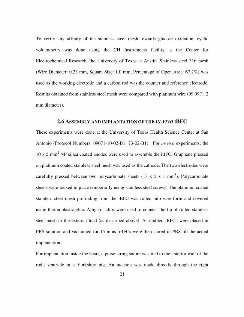
For implantation inside the heart, a purse-string suture was tied to the anterior wall of the
right ventricle in a Yorkshire pig. An incision was made directly through the right
22
ventricular myocardium. The iBFC was inserted into the right ventricular chamber and
the purse-string closed to maintain hemostasis. In the second in-vivo experiment, the
device was inserted in the right atrium of the pig to minimize the blood flow disruption.
Figure 8 shows a view of the open heart surgical preparation with the wire leads coming
out from the atrium after implantation. The pigs were later sacrificed using standard and
humane euthanasia procedures.
Figure 8: Photograph showing the iBFC implanted inside the swine heart (in Right
Auricle) with Stainless Steel mesh-wires coming out (marked by arrows)

23
3. RESULTS
3.1 NANOPOROUS SILICA
Using a spectroscopic ellipsometer, tested thin film thickness and porosity was measured
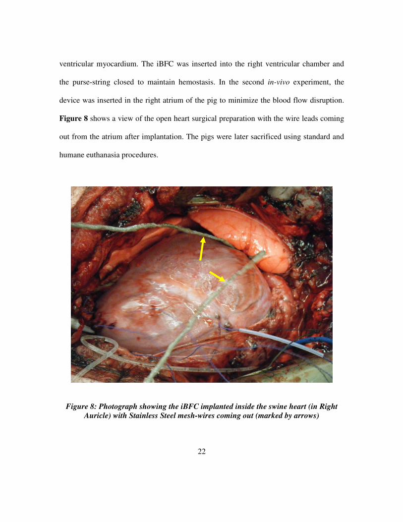
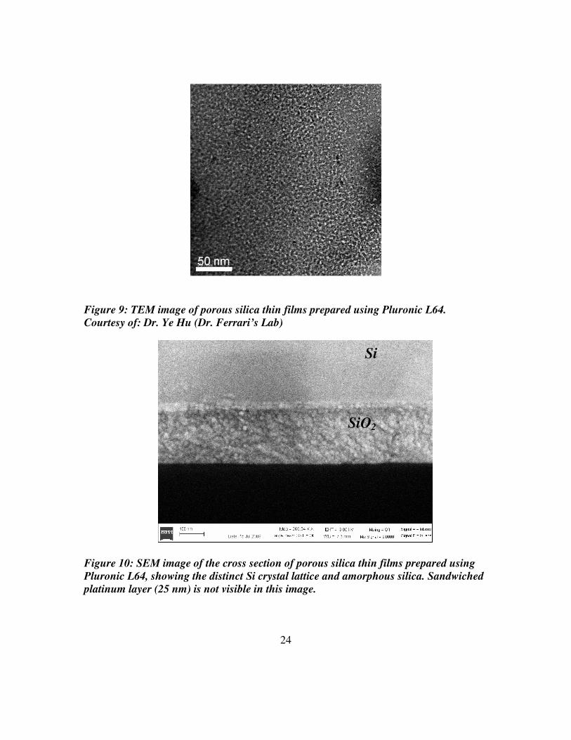
to be 281.816 ± 7.46 nm and 44.8815 ± 0.125%. In Figure 9, the TEM image of the plane
view of the nanoporous silica thin film depicts a worm-like nanostructure overlying the
porous layer. In Figure 11, N2 adsorption/desorption curves were generated using a
Quantachrome Autosorb-3b BET Surface Analyzer (inset) and the pore size distribution
(3.2nm) was calculated using the Barrett-Joyner-Halenda (BJH) method. The
adsorption/desorption isotherms describe a Type IV isotherm with a H2 hysteresis loop
(sloping adsorption branch and nearly vertical desorption branch), indicating a
nanoporous silica structure with interconnecting channels. Inflection points appearing at
0.40 <P/P0< 0.75 in Figure 11 indicated the formation of an ink-bottle shape nanopores.
Samples of NP Silica obtained after autoclaving did not show any changes in the
structure or thickness of the Nanoporous silica observed by SEM imaging and
Ellipsometry, proving the process was suitable for standard sterilization in a clinical
setting (Data not shown).
24
Figure 9: TEM image of porous silica thin films prepared using Pluronic L64.
Courtesy of: Dr. Ye Hu (Dr. Ferrari’s Lab)
Figure 10: SEM image of the cross section of porous silica thin films prepared using
Pluronic L64, showing the distinct Si crystal lattice and amorphous silica. Sandwiched
platinum layer (25 nm) is not visible in this image.
Si
SiO2

25
Figure 11: N2 adsorption/desorption analysis (pore size distribution and isotherms in
the insets), of the porous silica thin films prepared using Pluronic L64. Courtesy of:
Dr. Ye Hu (Dr. Ferrari’s Lab)
Contact Angle measurements showed that the platinum deposited on silicon wafer was
strongly hydrophobic, which was not expected [54]. Metal surfaces have been known to
be hydrophilic in general. The metallic surface might show hydrophobic properties due to
the residual hydrogen atoms bound to the platinum atoms. However, having a
hydrophobic metal surface might have aided assembly of nanoporous silica, which was
previously coated on hydrophobic silicon surface [55].

26
Figure 12: Contact angle measurements showing the water-surface contact angles for:
(a) Platinum deposited on Silicon wafer, (b) NP silica on Pt/Si anode; and (c)
Surfactant coated polypropylene membrane. The values have been summarized in
Table 4. Courtesy of: Dr. Ye Hu (Dr. Ferrari’s Lab)
Surfactant coated polypropylene was found to be hydrophobic as well. Polypropylene is
well-known to show hydrophobic behavior by virtue of the carbon chains constituting the
polymer. However, the membrane is surfactant coated for rapid wetting purposes, making
it hydrophilic. The results suggest that the surfactant coating might have degraded with
time changing the membrane surface from hydrophilic to hydrophobic. Hence, the
stability of the surface coating is also a major concern for long-duration implantable
applications. Nanoporous silica coating was found to have a stable shelf life in other
studies [56, 57].
Table 4: Summary of the various contact angles for different surfaces used in the
experiments.
Component Contact
Angle Hydrophobic/Hydrophilic
Pt (25 nm) deposited on Si wafer 82.41 Hydrophobic
NP Silica on Pt (25 nm) deposited on Si wafer
17.42 Hydrophilic
Surfactant coated Polypropylene membrane
61.70 Weak Hydrophobic
(a) (b) (c)

27
3.2 BIOFUEL CELL PERFORMANCE
3.2.1 STAINLESS STEEL AS CURRENT COLLECTOR
Literature suggest the use of Platinum mesh as the most preferred current collector [23].
However the costs associated with platinum mesh forced us to seek for other alternatives.
1.0 0.8 0.6 0.4 0.2 0.0 -0.2 -0.4 -0.6 -0.8 -1.0
-0.00003
-0.00002
-0.00001
0.00000
0.00001
0.00002
0.00003
-0.0004
-0.0003
-0.0002
-0.0001
0.0000
0.0001
1.0 0.8 0.6 0.4 0.2 0.0 -0.2 -0.4 -0.6 -0.8 -1.0
Cu
rre
nt
(A)
Voltage (V)
Pt wire vs Carbon in Argon
Cu
rre
nt (A
)
Stainless Steel mesh vs Carbon in Argon
Figure 13: Cyclic Voltammetry graphs of Stainless Steel Mesh and Pt Wire showing
that Stainless Steel mesh has no affinity for glucose and hence is a suitable current
collector material

28
Stainless Steel is known for its stability and biocompatibility [58]. However, no
published information is available on the use of stainless steel mesh as a current collector
for biofuel cells. Hence, cyclic voltammetry experiments were done to check for the
glucose affinity to stainless steel mesh. Figure 13 shows the obtained data from cyclic
voltammetry of stainless steel mesh versus platinum wire where carbon rod was used as
the counter and the reference electrode. From Figure 13 we observe that there was no
glucose oxidation peak observed in the case of stainless steel mesh as was in the case of
platinum wire (0.4 V). Further, oxygen reduction can be observed in Pt wire (-0.6 V).
However, the oxygen reduction is prominent in the case of Platinum, indicating the
higher affinity of platinum towards oxygen. From these results, it can be concluded that
stainless steel mesh can be a good current collector as it would not introduce any error
which can be due to oxidation of glucose on stainless steel mesh. More tests need to be
done with better controls and reference electrodes to confirm this. However while all the
studies reported use a platinum mesh, we have used stainless steel mesh as the cathodic
current collector in the present study for consistency.
3.2.2 PERFORMANCE AT 0.42% GLUCOSE
Power density and polarization curves for the two BFCs have been plotted in Figure 6.
From Figure 6a, it is clear that the replacement of activated carbon with graphene as the
cathode can deliver high power densities (Pt/PP/G: 5 µW/cm2). Hence graphene acts as a
better cathode in place of activated carbon (Pt/PP/AC: 3.24 µW/cm2). Further, the open
circuit potential (OCP) of graphene based BFC (Pt/PP/G: 0.261 V) was higher compared
to the OCP of activated Carbon based BFC (Pt/PP/G: 0.234 V). The power densities
reported in the present study obtained from activated carbon (Pt/PP/AC: 3.24 µW/cm2)

29
based BFC are higher than the values reported from similar studies (~2 µW/cm2) [48].
Higher power densities may be attributed to higher glucose concentrations used to
compensate for the presence of oxygen at atmospheric pressure conditions.
30 35 40 45 50 55 60 65 70 75
-0.5
0.0
0.5
1.0
1.5
2.0
2.5
3.0
3.5
4.0
4.5
5.0
5.5
6.0
6.5P
ow
er
De
nsity (
uW
/cm
2)
Current Density (µA/cm2)
Pt/PP/AC
Pt/PP/G
Pt/NP/G
0 10 20 30 40 50 60 70 80
0
50
100
150
200
250
300
Vo
lta
ge
(m
V)
Current Density (µA/cm2)
Pt/PP/AC
Pt/PP/G
Pt/NP/G
Figure 14: Experimental results obtained with Polymer membrane vs. Nanoporous Silica
based BFCs: (a) Power Density Curves, and (b) Polarization Curves
NP silica based iBFC (Pt/NP/G) is capable of delivering higher power densities (6.23
(a)
(b)

30
µW/cm2) than the polymer membrane based iBFC (Pt/PP/G: 5 µW/cm2). The lower OCP
obtained using NP silica based iBFC (Pt/PP/G: 183.2 mV) indicates the presence of
oxygen at the anode. The absolute values of polarization recorded are very low compared
to the reported literature values [48]. This is an indication of the possible interference of
oxygen at the anode which in turn, could be due to inadequate clamp pressure from the
polycarbonate sheets as well as diffusion of oxygen through PDMS. Further, this could
also possibly be due to the presence of residual air in graphene that was not removed
during vacuuming. The polarization values were found to improve with time, however.
Better BFC designs for the presented electrode system should avoid the observed low
polarization values for the two BFCs.
3.2.3 PERFORMANCE AT 0.1% GLUCOSE
0.1 % glucose is reported the physiological glucose concentration. Pt/NP/G iBFC (5.3
µW/cm2) shows higher power density compared to Pt/PP/G iBFC (2.1 µW/cm2)
indicating better performance of the iBFC when the polypropylene membrane was
replaced with nanoporous silica membrane. Figure 15 shows the comparison of the
power densities and polarization values obtained from the various iBFCs assembled.
Appleby et. al. [15] have reported that introduction of oxygen causes an appreciable
change in the open circuit potentials; there is minimal effect on the polarization curve.
Pt/NP/G shows significantly higher open circuit potential (314.6 mV) compared to
Pt/PP/G (181.4mV) and Pt/PP/AC (160 mV) while both the iBFCs show similar ohmic
losses, determined by the slope of the curves.

31
0 10 20 30 40 50
0
1
2
3
4
5
6
Po
we
r D
en
sity (
µW
/cm
2)
Current Density (µA/cm2)
Pt/PP/AC
Pt/PP/G
Pt/NP/G
0 10 20 30 40 50
0
20
40
60
80
100
120
140
160
180
200
220
240
260
280
300
320
340
Volta
ge
(m
V)
Current Density (µA/cm2)
Pt/PP/AC
Pt/PP/G
Pt/NP/G
Figure 15: Experimental results obtained with Polymer membrane vs. Nanoporous
Silica based BFCs: (a) Power Density Curves, and (b) Polarization Curves
(a)
(b)
32
An irreversible polarization change was observed upon disruption or change of operating
conditions including changing of electrolytes as reported earlier [23]. Hence, long-term
experiments (> 48 hours) could not be recorded.
Qu proposed that oxygen reduction in activated carbon occurs at the edges of the
graphene layers that make up the structure of activated carbon whereas the micropores
may not be used for oxygen reduction [59]. Graphene based cathodes used in the present
study contain several graphene layers bound together using PTFE. Activated carbon
based cathodes on the other hand contain several amorphous activated carbon granules
bound using PTFE. Hence, only a fraction of the whole activated carbon granule surface
would be chemically active. Graphene as a cathode shows considerable increase in
performance (2.1 µW/cm2) compared to similar setup based on activated carbon (1.1
µW/cm2) in the present study.
3.3.4 COMPARISON OF PERFORMANCE
All the iBFCs operated at 0.1% glucose solution showed lower power density compared
to 0.42% glucose solution. Lower power density was mainly due to the lower glucose
concentration used (0.1%) and better represents the physiological glucose values. The
presence of oxygen also had a visible effect on the open circuit potential of the iBFCs,
which was lower for the iBFCs in the present study. Important values have been
summarized in Table 5.

33
3.3.5 COMPARISON OF PERFORMANCE WITH OTHER REPORTED LITERATURE RESULTS
Table 5: Comparison of some iBFC performance with their components and
operational conditions
Anode
(µm)
Membrane
(µm)
Cathode
(µm)
Glucose
concentration
(% w/v)
Oxygen
concentration
(% w/v)
Max.
Power
Density
(µW/cm2)
Reference
Activated Carbon + 10% Pt
3% PVA-PAA (30 µm)
Activated Carbon
0.1% Air 1.4 [60]
Activated Carbon + Pt-Bi (540
µm)
Polypropylene (90 µm)
Activated carbon
(400 µm) 0.1 % Air 3.5 [12]
Pt (25 nm)
Polypropylene (50 µm)
Activated Carbon
(200 µm) 0.1% Air 1.1
This Study
Pt (25 nm)
Polypropylene (50 µm)
Graphene (185 µm)
0.1 % Air 2.1 This
Study
Pt (25 nm)
NP Silica (278 nm)
Graphene (185 µm)
0.1% Air 5.3 This
Study
Pt (25 nm)
Polypropylene (50 µm)
Activated Carbon
(200 µm) 0.42% Air 3.5
This Study
Pt (25 nm)
Polypropylene (50 µm)
Graphene (175 µm)
0.42% Air 5.0 This
Study
Pt (25 nm)
NP Silica (270 nm)
Graphene (175 µm)
0.42% Air 6.25 This
Study
Activated Carbon + 5%Pt + 5% Bi
(480 µm)
Polyether- sulfone
(140 µm)
Activated Carbon
(480 µm) 0.1% 4 % 3.3 [48]
The power densities reported in the present study obtained from activated carbon (1.1

34
µW/cm2) based BFC are lower compared values reported by Kerzenmacher et al. (~ 2
µW/cm2)[48]. Lower power densities could be due to the reduced thickness of electrodes
such as activated carbon cathode (200 µm) used in the present study compared to most of
other studies employing thicker cathodes (400-800 µm) [23]. Carbon based cathodes help
remove the oxygen from the incoming mixture of glucose and oxygen. Hence optimal
cathode thickness is necessary to ensure anaerobic environment at the anode. Thus
reduction in the membrane thickness can play a pivotal role in the overall reduction of the
iBFC thickness without compromise in performance.
3.3.6 PERFORMANCE OF IN-VIVO IBFC
The potential of Pt/NP/G was further demonstrated by the in-vivo experiments. Figure 16
shows the performance of the device when implanted. In comparison, the implanted
device performed much better in-vivo (10 µW/cm2, Figure 16) than in-vitro (6 µW/cm2,
Figure 15) due to the six times lower oxygen concentration in venous blood and high
blood flow rates. The total time of the study was 12 minutes before the pig died. In
another experiment extending over 50 mins, deposition of blood clots and fibrinogenic
coating was noticed on the surface of the device (Figure 17). However, the device
continued to deliver constant power output over the period of 50 minutes because glucose
is diffusible through clots, suggesting operation will be successful in the presence of neo-
intima.
35
20 40 60 80 100 120 140
3
4
5
6
7
8
9
10
11
Pow
er
De
nsity (
µW
/cm
2)
Current Density (µA/cm2)
0
50
100
150
200
250
300
350
Volta
ge
(m
V)
Figure 16: Plot for in-vivo studies showing the high power density obtained from iBFC
Figure 17: Photograph of the device after removal from the heart of the animal
showing blood clots and fibrinogenic deposition on the entire device surface
5 mm

36
4. DISCUSSIONS
Many studies have focused on the development of enzymatic biofuel cells using
immobilized enzymes for anodes and/or cathodes. High power densities in the mW/cm2
ranges have been reported from such systems [24, 30, 61]. However, numerous problems
are associated with the usage of enzyme based iBFCs. Effective transport of electrons
from the site of catalysis to electrode surface, durability of enzymes under physiological
conditions and operational pH ranges, biocompatibility of enzymes and electron
mediators and sterilization challenges still remain largely unaddressed. Irrespective of the
type of biofuel cell, a major advantage of tissue-implanted biofuel cells is that their
implantation is surgically less challenging [23]. The current study reports a viable
solution to the aforementioned problems. The iBFC presented in our study presents an
attractive alternative to enzymatic biofuel cells in terms of sterility, biocompatibility,
stability and performance. The use of inorganic materials in the construction of the
current iBFC negates the problem of delamination and sterilization. The autoclaving
results corroborate this fact. Although the biocompatibility of graphene has not been
proven yet, the precursor material, graphene paper, has been documented to be
biocompatible [62]. With the use of nanoporous silica, we have also addressed the
problem commonly encountered with most other polymeric membranes used in iBFCs of
swelling and pus accumulation. Further, selective functionalization of nanoporous silica
may promote glucose diffusion for the creation of better, more efficient iBFCs.

37
Contact angle measurements showed that the surfactant-coated polypropylene membrane
was hydrophobic in nature. Hydrophobicity may have been due to degradation of the
surfactant coating, which makes the surface hydrophilic for rapid wetting. It was
anticipated that Pt/NP/G would perform better than Pt/PP/G iBFC due to the weakly ionic
nature of the NP silica structure. Ionic conductive membranes are desired for effective
diffusion of the fuel and its reaction product to and from the anode [23]. With appropriate
functionalization of the surface and the pore walls, the hydrophilicity of the membrane
can be precisely controlled to give the desirable membrane in ultra-thin format. The
significantly higher open circuit potential of Pt/NP/G can be attributed to the ability of
NP silica membrane in limiting oxygen crossover.
The power performance of the presented iBFCs were considerably higher than other
literature values (Table 5) indicating the contribution of graphene and NP silica towards
increasing the power output. Moreover, the iBFCs described here were tested under a
21% oxygen saturation condition. At physiological levels of oxygen saturation (5%),
even higher power densities can be expected from the same iBFCs. An example of this
would be the in-vivo performance of the Pt/NP/G iBFC which showed a power density as
high as 10 µW/cm2 - the highest power density obtained so far for an iBFC based on
inorganic metal catalysts. With such a high power density output, the lifetime of a
pacemaker (Table 1) can be extended from 7 yrs to 12 yrs. However, long duration
experiments need to be performed to confirm the continuous performance of the iBFC
over such time scales. Other studies have shown functional capability of iBFC in-vitro for

38
235 days and in-vivo up to 150 days. No reports are given of chronic implanted iBFC in
blood vessels. I anticipate that devices implanted in blood vessels are subject to both
greater glucose levels and neo-intimal tissue thicknesses. An important objective is to
evaluate the chronic performance of an intra-vascular implanted iBFC.
We have also taken into consideration the surgical problems associated with an intra-
vascular iBFC. The most common problems with conventional design of intra-vascular
iBFCs are: (1) bulky nature of iBFC that can hinder the blood flow; and (2) mechanical
stability [23]. Use of advanced nanomaterials can allow fabrication of ultra-thin iBFC
capable of delivering very high power densities, which was not feasible for earlier iBFC
designs. Further, the layered-structure can be transferred to a stent shaped platform, stent
material itself acting as the anode. By creating a venous implant, the iBFC would be
subjected to reduced rheological pressure conditions. When compared to arteries, large
veins carry deoxygenated blood even though the glucose levels are almost equivalent
[23]. Hence fabricating an ultra-thin iBFC on top of a venous stent would be a viable
solution for the problems encountered by iBFCs. An added advantage of using of a stent
as the supporting base is the convenience of using stents in surgical procedures. The long
term aim is to enable creation of efficient, ultra-thin implantable Biofuel Cells (iBFCs) which
could be mounted on stents and deployed in veins
39
5. CONCLUSIONS
We presented results on the use of nanoporous silica as a functional membrane and
graphene as cathode for the fabrication of an ultra-thin implantable biofuel cells. Load
characteristics were measured for the assembled iBFCs and showed the potential of using
nanoporous silica as a membrane for an iBFC. We also observed higher current densities
from the nanoporous silica based iBFC than 3 µW/cm2. Further experiments need to be
completed to establish the significant advantages of using NP silica along with its
optimization. As nanoporous silica and graphene processing are becoming semiconductor
clean-room friendly, the future holds great promise for the development of mass-
producible, high power-density, ultra-thin biofuel cells for biomedical implant
applications.

40
6. REFERENCES
1. Writing Group, M., et al., Heart Disease and Stroke Statistics--2009 Update: A
Report From the American Heart Association Statistics Committee and Stroke
Statistics Subcommittee. Circulation, 2009. 119(3): p. e21-181.
2. Cho, S. and C. Kang, Nonenzymatic glucose detection with good selectivity
against ascorbic acid on a highly porous gold electrode subjected to
amalgamation treatment. Electroanalysis, 2007. 19(22): p. 2315-2320.
3. Clauwaert, P., et al., Minimizing losses in bio-electrochemical systems: the road
to applications. Applied Microbiology and Biotechnology, 2008. 79(6): p. 901-
913.
4. Dargahi, J., A piezoelectric tactile sensor with three sensing elements for robotic,
endoscopic and prosthetic applications. Sensors and Actuators A: Physical, 2000.
80(1): p. 23-30.
5. Lisichkin, G.V. and A.A. Kudrinskii, Grafted surface compounds in chemical
sensors and biosensors. Russian Journal of General Chemistry, 2007. 77(3): p.
325-335.
6. Lu, X.B., et al., Carbon nanofiber-based composites for the construction of
mediator-free biosensors. Biosensors & Bioelectronics, 2008. 23(8): p. 1236-
1243.

41
7. Melde, B.J., B.J. Johnson, and P.T. Charles, Mesoporous silicate materials in
sensing. Sensors, 2008. 8(8): p. 5202-5228.
8. Najafi, N. and A. Ludomirsky, Initial animal studies of a wireless, batteryless,
MEMS implant for cardiovascular applications. Biomedical Microdevices, 2004.
6(1): p. 61-65.
9. Sokhanvar, S., M. Packirisamy, and J. Dargahi, MEMS Endoscopic Tactile
Sensor: Toward In-Situ and In-Vivo Tissue Softness Characterization. Ieee
Sensors Journal, 2009. 9(12): p. 1679-1687.
10. Zhang, J. and J. Zhu, A novel amperometric biosensor based on gold
nanoparticles-mesoporous silica composite for biosensing glucose. Science in
China Series B: Chemistry, 2009. 52(6): p. 815-820.
11. Chau, H.L. and K.D. Wise, An Ultraminiature Solid-State Pressure Sensor for a
Cardiovascular Catheter. IEEE Transactions on Electron Devices, 1988. 35(12):
p. 2355-2362.
12. F. von Stetten, S.K., R. Sumbharaju, R. Zengerle, and J. Ducrée. Biofuel cells as
micro power generators for implantable devices. in Proc. Eurosensors XX. 2006.
13. Medmovie.com, Medmovie 2004 Cardiac Illustration, in medmovie.com,
0057iStent, Editor. 2004: Lexington.
14. Appleby, A.J., D.Y.C. Ng, and H. Weinstein, Parametric study of the anode of an
implantable biological fuel cell. Journal of Applied Electrochemistry, 1971. 1(2):
p. 79-90.

42
15. Appleby, A.J. and C. Van Drunen, Anodic Oxidation of Carbohydrates and
Related Compounds in Neutral Saline Solution. Journal of The Electrochemical
Society, 1971. 118(1): p. 95-97.
16. Kreysa, G., D. Sell, and P. Kramer, Bioelectrochemical Fuel-Cells. Berichte Der
Bunsen-Gesellschaft-Physical Chemistry Chemical Physics, 1990. 94(9): p. 1042-
1045.
17. Rao, J.R., et al., Performance of Glucose Electrodes and Characteristics of
Different Biofuel Cell Constructions. Bioelectrochemistry and Bioenergetics,
1976. 3(1): p. 139-150.
18. Mele, M.F.L.D., M.J. Cardos, and H.A. Videla, A Biofuel Cell as a
Bioelectrochemical Sensor of Glucose-Oxidation. Anales De La Asociacion
Quimica Argentina, 1979. 67(4): p. 125-138.
19. Weidlich, E., et al., Animal-Experiments with Bio-Galvanic and Bio-fuel Cells.
Biomaterials Medical Devices and Artificial Organs, 1976. 4(3-4): p. 277-306.
20. Ramanavicius, A., A. Kausaite, and A. Ramanaviciene, Biofuel cell based on
direct bioelectrocatalysis. Biosensors & Bioelectronics, 2005. 20(10): p. 1962-
1967.
21. Prauer, H.W., et al., Lithium-Powered Cardiac-Pacemakers. Medizinische Klinik,
1977. 72(44): p. 1885-1891.
22. Cinquin, P., et al., A Glucose BioFuel Cell Implanted in Rats. PLoS ONE. 5(5): p.
e10476-e10476.

43
23. Kerzenmacher, S., et al., Energy harvesting by implantable abiotically catalyzed
glucose fuel cells. Journal of Power Sources, 2008. 182(1): p. 1-17.
24. Fernandez, J.L., et al., Optimization of "wired" enzyme O-2-electroreduction
catalyst compositions by scanning electrochemical microscopy. Angewandte
Chemie-International Edition, 2004. 43(46): p. 6355-6357.
25. Mano, N., A miniature membrane-less biofuel cell operating at+0.60 V under
physiological conditions. Abstracts of Papers of the American Chemical Society,
2005. 230: p. U1661-U1661.
26. Minteer, S.D., B.Y. Liaw, and M.J. COoney, Enzyme-based biofuel cells. Current
Opinion in Biotechnology, 2007. 18(3): p. 228-234.
27. Boland, S., et al., Biocatalytic fuel cells: A comparison of surface pre-treatments
for anchoring biocatalytic redox films on electrode surfaces. Journal of
Electroanalytical Chemistry, 2009. 626(1-2): p. 111-115.
28. Rao, J.R., Bioelectrochemistry. I. Biological Redox Reactions,, M.B. G. Milazzo,
Editor. 1983,, Plenum Press, New York. p. 283–335.
29. A. Kloke, B.B., S. Kerzenmacher, U. Kräling, R. Zengerle, and F. von Stetten. A
single layer biofuel cell as potential coating for implantable low power devices. in
Eurosensors Proceedings. 2008.
30. Bartlett, P.N. and E. Simon, Poly(aniline)-poly(acrylate) composite films as
modified electrodes for the oxidation of NADH. Physical Chemistry Chemical
Physics, 2000. 2(11): p. 2599-2606.

44
31. Chen, T., et al., A miniature biofuel cell. Journal of the American Chemical
Society, 2001. 123(35): p. 8630-8631.
32. Saffarian, H.M., et al., Acceleration of oxygen reduction rate by alkyl derivatives
of uracil on Pt catalysts used in fuel cells. Journal of the Electrochemical Society,
2001. 148(6): p. A559-A564.
33. Tsujimura, S., K. Kano, and T. Ikeda, Glucose/O-2 biofuel cell operating at
physiological conditions. Electrochemistry, 2002. 70(12): p. 940-942.
34. Mano, N., et al., An oxygen cathode operating in a physiological solution. Journal
of the American Chemical Society, 2002. 124(22): p. 6480-6486.
35. Wong, T.S. and U. Schwaneberg, Protein engineering in bioelectrocatalysis.
Current Opinion in Biotechnology, 2003. 14(6): p. 590-596.
36. Soukharev, V., N. Mano, and A. Heller, A four-electron O-2-electroreduction
biocatalyst superior to platinum and a biofuel cell operating at 0.88 V. Journal of
the American Chemical Society, 2004. 126(27): p. 8368-8369.
37. Barriere, F., P. Kavanagh, and D. Leech, A laccase-glucose oxidase biofuel cell
prototype operating in a physiological buffer. Electrochimica Acta, 2006. 51(24):
p. 5187-5192.
38. Furukawa, Y., T. Moriuchi, and K. Morishima, Design principle and prototyping
of a direct photosynthetic/metabolic biofuel cell (DPMFC). Journal of
Micromechanics and Microengineering, 2006. 16(9): p. S220-S225.

45
39. Habrioux, A., et al., Concentric glucose/O-2 biofuel cell. Journal of
Electroanalytical Chemistry, 2008. 622(1): p. 97-102.
40. Zebda, A., et al., A microfluidic glucose biofuel cell to generate micropower from
enzymes at ambient temperature. Electrochemistry Communications, 2009. 11(3):
p. 592-595.
41. Colmati, F., et al., Enzymatic based biocathode in a polymer electrolyte
membrane fuel cell. International Journal of Electrochemical Science, 2007. 2(2):
p. 195-202.
42. Kang, C., H. Shin, and A. Heller, On the stability of the "wired" bilirubin oxidase
oxygen cathode in serum. Bioelectrochemistry, 2006. 68(1): p. 22-26.
43. Beltzer, M.B., J. S. Limitations of blood plasma as a fuel cell electrolyte. in Proc.
Intersoc. Energy Convers. Eng. Conf., 4th. 1969.
44. Barton, S.C. and P. Atanassov, Enzymatic biofuel cells for implantable and micro-
scale devices. Abstracts of Papers of the American Chemical Society, 2004. 228:
p. 004-FUEL.
45. Bruno, M.M., et al., Electrodeposited platinum catalysts over hierarchical carbon
monolithic support. Journal of Applied Electrochemistry, 2009. 40(2): p. 257-263.
46. Habrioux, A., et al., Activity of platinum-gold alloys for glucose electrooxidation
in biofuel cells. Journal of Physical Chemistry B, 2007. 111(34): p. 10329-10333.
46
47. Jin, C. and Z. Chen, Electrocatalytic oxidation of glucose on gold-platinum
nanocomposite electrodes and platinum-modified gold electrodes. Synthetic
Metals, 2007. 157(13-15): p. 592-596.
48. Kerzenmacher, S., et al., An abiotically catalyzed glucose fuel cell for powering
medical implants: Reconstructed manufacturing protocol and analysis of
performance. Journal of Power Sources, 2008. 182(1): p. 66-75.
49. Gebhardt, U.R., J.R.; Richeter, G.J., A Special Type of Raney-alloy catalyst used
in compact Biofuel Cells. Journal of Applied Electrochemistry, 1976. 6: p. 127-
134.
50. Gupta, G., et al., Highly Stable and Active Pt−Cu Oxygen Reduction
Electrocatalysts Based on Mesoporous Graphitic Carbon Supports. Chemistry of
Materials, 2009. 21(19): p. 4515-4526.
51. Kloke, A.K., S.; Zengerle, R., Stetten, F. von, Electrodeposited thin-layer
electrodes for he use in Potentially implantable Glucose Fuel cells, in
Transducers. 2009: Denver, CO, USA. p. 537-540.
52. Stoller, M.D., et al., Graphene-Based Ultracapacitors. Nano Letters, 2008. 8(10):
p. 3498-3502.
53. Choi, Y.K., et al., A hybrid biofuel cell based on electrooxidation of glucose using
ultra-small silicon nanoparticles. Biosensors & Bioelectronics, 2009. 24(10): p.
3103-3107.

47
54. Shi, B., S. Sinha, and V.K. Dhir. Molecular simulation of the contact angle of
water droplet on a platinum surface. in ASME International Mechanical
Engineering Congress and Exposition, Novement 5. 2005.
55. Hu, Y.B., Ali; Liu, Xuewu; Tasciotti, Ennio; Li, Li; Ferrari, Mauro. The next
generation of proteomic nanochips in biomarker discovery. in Nanotech
Conference & Expo 2009: An Interdisciplinary Integrative Forum on
Nanotechnology, Biotechnology and Microtechnology. 2009.
56. Bouamrani, A., et al., Mesoporous silica chips for selective enrichment and
stabilization of low molecular weight proteome. Proteomics, 2009. 10(3): p. 496-
505.
57. Hu, Y., et al., Tailoring of the Nanotexture of Mesoporous Silica Films and Their
Functionalized Derivatives for Selectively Harvesting Low Molecular Weight
Protein. ACS Nano, 2010. 4(1): p. 439-451.
58. Airoldi, F., et al., Comparison of diamond-like carbon-coated stents versus
uncoated stainless steel stents in coronary artery disease. The American Journal
of Cardiology, 2004. 93(4): p. 474-477.
59. Qu, D., Investigation of oxygen reduction on activated carbon electrodes in
alkaline solution. Carbon, 2007. 45(6): p. 1296-1301.
48
60. Stetten, F.v.K., S; Lorenz, A.; Chokkalingam, V.; Miyakawa, N.; Zengerle, R.;
Ducree, J., A One-Compartment, Direct Glucose Fuel Cell for Powering Long-
term Medical Implants, in MEMS 2006. 2006, IEEE: Istanbul, Turkey. p. 934-
937.
61. Komaba, S., T. Mitsuhashi, and S. Shiraishi, Polyion complex nanocomposite
electrode incorporating enzyme and carbon nanotube for biofuel cells.
Electrochemistry, 2008. 76(1): p. 55-58.
62. Chen, H., et al., Mechanically Strong, Electrically Conductive, and Biocompatible
Graphene Paper. Advanced Materials, 2008. 20(18): p. 3557-3561.

49
VITA
Tushar Sharma was born in Mandi, a small town in the valleys of Himachal Pradesh,
India. He did his undergraduate studies in the Biotechnology Department at The Indian
Institute of Technology Madras, India. He graduated with a Bachelors in Technology
from Indian Institute of Technology Madras in June 2008. He also received the
prestigious Bhagyalakshmi and Ayengar Award for the best B. Tech. Thesis. In August
2008, he entered the Graduate School at The University of Texas at Austin.
Permanent Address: Flat No 6, Shivmala Apts
Makarpura Road, Vadodara – 09
Gujarat, India
This thesis was typed by the author