Copyright © 2007-2008 Gregory Avady. All rights reserved. Electro-optical 3D Metrology Gregory...
15
Copyright © 2007-2008 Gregory Avady. All rights reserved. Electro-optical 3D Metrology Gregory Avady, Ph.D. Overview
-
Upload
meredith-brisley -
Category
Documents
-
view
214 -
download
0
Transcript of Copyright © 2007-2008 Gregory Avady. All rights reserved. Electro-optical 3D Metrology Gregory...

Copyright © 2007-2008 Gregory Avady. All rights reserved.
Electro-optical 3D Metrology
Gregory Avady, Ph.D.
Overview

Copyright © 2007-2008 Gregory Avady. All rights reserved.
3D Metrology3D Metrology
• Purpose:– Find target’s coordinates or orientation in
3D space
• Resources:– One or more optoelectronic sensors
(cameras)– Some knowledge of the target, such as:
geometry (shape), color, brightness, approximate location

Copyright © 2007-2008 Gregory Avady. All rights reserved.Control Device
Typical Block-DiagramTypical Block-Diagram
X
Y
Z
O
XO
YOZO
OO
X1
Y1
Z1
O1
X2
Y2
Z2
O2
ZN
XN
YN
ON
Sensor 1
Sensor 2 Sensor N
Processor
Acquisition Device
Output Target
Laser Designator(Optional)

Copyright © 2007-2008 Gregory Avady. All rights reserved.
System ClassificationsSystem Classifications• Target Profile
– Cooperative– Non-Cooperative
• Illumination Type– Active Systems (using laser designator)– Passive Systems
• Sensor Type– 2D sensors (standard cameras)– 1D sensors (linear CCD cameras)– Single element sensors (photodiodes)
• Metrology Objective– Range or angular position– 3D measurement– Orientation measurement

Copyright © 2007-2008 Gregory Avady. All rights reserved.
Cooperative ConfigurationCooperative Configuration• Known target geometry (including distance
between reference marks)• Some reference marks under system control
(each mark can be turned on or off in any time)
• Typical Procedure:– For each mark:
• Activate mark• Acquire image• Measure 3D mark’s coordinates
– Calculate target orientation

Copyright © 2007-2008 Gregory Avady. All rights reserved.
Non Cooperative ConfigurationNon Cooperative Configuration
• Known target geometry (including distance between reference marks)
• The most difficult steps are:– Identification of reference marks by using:
• Mutual location of marks
• Previous target and / or marks location
– Finding corresponding marks on all camera images

Copyright © 2007-2008 Gregory Avady. All rights reserved.
Illumination TypesIllumination Types
• Active System– External target illumination
– If laser designator orientation is known then one 2D sensor (or two 1D sensors) may be removed
• Passive System– Only target’s features are used
– System is not detectable from the target
Copyright © 2007-2008 Gregory Avady. All rights reserved.
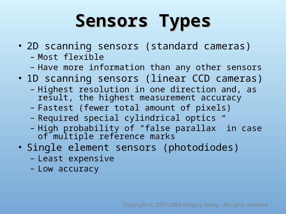
Sensors TypesSensors Types• 2D scanning sensors (standard cameras)
– Most flexible – Have more information than any other sensors
• 1D scanning sensors (linear CCD cameras)– Highest resolution in one direction and, as result, the
highest measurement accuracy– Fastest (fewer total amount of pixels)– Required special cylindrical optics– High probability of “false parallax” in case of multiple
reference marks• Single element sensors (photodiodes)
– Least expensive– Low accuracy

Copyright © 2007-2008 Gregory Avady. All rights reserved.
F
Individual Pixels…
Z
X
Y
1D Scanning Sensors1D Scanning Sensors
Cylindrical Optics

Copyright © 2007-2008 Gregory Avady. All rights reserved.
Single Element Sensor ConceptSingle Element Sensor Concept
Half Mirror
Mirror
Object
Active Sensor
Reference Sensor
Optics
Variable Density Filter

Copyright © 2007-2008 Gregory Avady. All rights reserved.
Active System ConceptActive System Concept
2D Camera
Laser Designator
Target Surface
Xc
Yc
ZcOc
Xd
Yd
ZdOd
Reference Mark
Copyright © 2007-2008 Gregory Avady. All rights reserved.
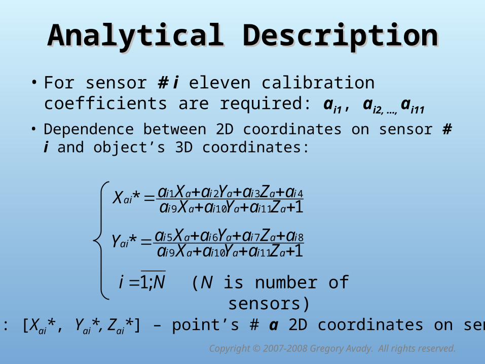
Analytical DescriptionAnalytical Description
• For sensor # i eleven calibration coefficients are required: ai1, ai2, …, ai11
• Dependence between 2D coordinates on sensor # i and object’s 3D coordinates:
Here: [Xai*, Yai*, Zai*] – point’s # a 2D coordinates on sensor # i
1*11109
4321
aiaiai
iaiaiaiai ZaYaXa
aZaYaXaX
Ni ;1 (N is number of sensors)
1*11109
8765
aiaiai
iaiaiaiai ZaYaXa
aZaYaXaY

Copyright © 2007-2008 Gregory Avady. All rights reserved.
Analytical Description (Direct Task)Analytical Description (Direct Task)
• The following system of linear equations is used for calculating 3D coordinates for selected point on the object:
*)*()*()*( 431121019 aiiaiaiiaiaiiaiaii XaZaXaYaXaXaXa
Ni ;1 (N – number of sensors)
*)*()*()*( 871161059 aiiaiaiiaiaiiaiaii YaZaYaYaYaXaYa
Here: [Xai*, Yai*, Zai*] – point’s # a 2D coordinates on sensor # i

Copyright © 2007-2008 Gregory Avady. All rights reserved.
Analytical Description (Inverse Task)Analytical Description (Inverse Task)
• The following equations are used for sensor # i calibration, i.e. for calculating coefficients ai1, ai2, …, ai11:
**** 111098765 ajiajajiajajiajajiiajiajiaj YaYZaYYaYXaaZaYaX **** 111094321 ajiajajiajajiajajiiajiajiaj XaXZaXYaXXaaZaYaX
Ni ;1 (N – number of sensors)(M – number of calibration data points)Mj ;1
Here: [Xai*, Yai*, Zai*] – point’s # a 2D coordinates on sensor # i [Xaj, Yaj, Zaj] – point’s # a 3D coordinates

Copyright © 2007-2008 Gregory Avady. All rights reserved.
Multi-Channel Processing ProcedureMulti-Channel Processing Procedure
• For each channel:– Acquire image– Filter acquired image– Find center of gravity for all marks on the image– Identify each mark by using:
• Mutual location of reference marks• Previous target / marks location (if known)
• Find corresponding marks on each camera image• Calculate each mark’s 3D coordinates• Calculate target’s orientation