General Application Regulations 2007 SI 2007 Unofficial Copy
Unoffic
ial C
opy
4719.02 1 Addendum No. 1
ADDENDUM TO CONTRACT DOCUMENTS
AND SPECIFICATIONS
Henry Street Interceptor Project For the City of New Iberia, LA
ADDENDUM NO. 1 SEPTEMBER 19, 2014
The following items shall take precedence over referenced to counterparts in the specifications, contract drawings and any other documents in conflict herewith. Item No. 1 PRIOR APPROVAL LIST: The following manufacturers’ equipment may be
considered for use on this project (they have received prior approval subject to the following):
The Engineer may allow minor deviations subject to the Engineer’s judgment as to whether such deviations would detract from the quality, reliability or function of the equipment. The equipment manufacturer shall be responsible for any and all redesign required to accommodate their equipment. All drawings and calculations detailing the deviations from the plans and specifications shall be submitted to the Engineer with the shop drawings for approval. Drawings must be in AutoCad 2010 or more recent format and must be stamped by an Engineer licensed in the State of Louisiana. Submit both hard copies and electronic copies for approval. Prior approval of other manufacturers’ equipment shall in no way relieve the Contractor of responsibility for submitting the specified shop drawings for approval or complying fully with all provisions of the specifications and drawings. If prior approved equipment is used, the contractor shall, at his own expense, make any changes or additions in the structures, piping, electrical, etc. as necessary to accommodate the equipment. If engineering is required due to substitution of prior approved equipment, the contractor shall furnish and pay for all such engineering services. No qualifications or exceptions listed in prior approval submittals shall in any way alter or serve as substitute provisions relative to this contract. Note: Although prior approval allows the manufacturer to bid the project in accordance with the documents, many of the features/items required by the specifications were listed as optional equipment by the manufacturer (e.g. stainless steel guides, two moisture probes, non-sparking assembly, etc.). It is the Contractor’s responsibility to ensure that the products used to determine the bid are in FULL compliance with the specifications, including the costs for the options required to fully meet the specifications.
Unoffic
ial C
opy

4719.02 2 Addendum No. 1
Section Description of Items Approved Mfr. 11300 Submersible Raw Sewage Pumps Chicago Pumps Item No. 2 REFER to the Specifications, Technical Section 02719, Part 2 – Products, Pipe, Valve
and Fitting Insulation. Goodtemp Thermal Industrial Insulation by Howred Corp., and Childers Aluminum Insulation Covers, may be substituted in lieu of the Thermazip insulation specified. The system shall include all fittings, strapping, etc., as provided by these manufacturers. All other requirements with regard to heat tracing and installation of the insulation remain in force.
Item No. 3 REFER to the Specifications, Technical Section 02730 and 02731. Note that all restored
pavement shall conform to the minimum course thicknesses outlined on the details for such work.
Item No. 4 REFER to the Specifications, Technical Section 02731, Measurement and Payment, B.
Force Mains. Delete the first sentence of this section and substitute the following:
Payment for force mains shall be based on the actual number of linear feet of pipe measured in place at the price bid per foot for each classification of force main listed on the bid form, by diameter and pipe material, as designated on the Bid Form.
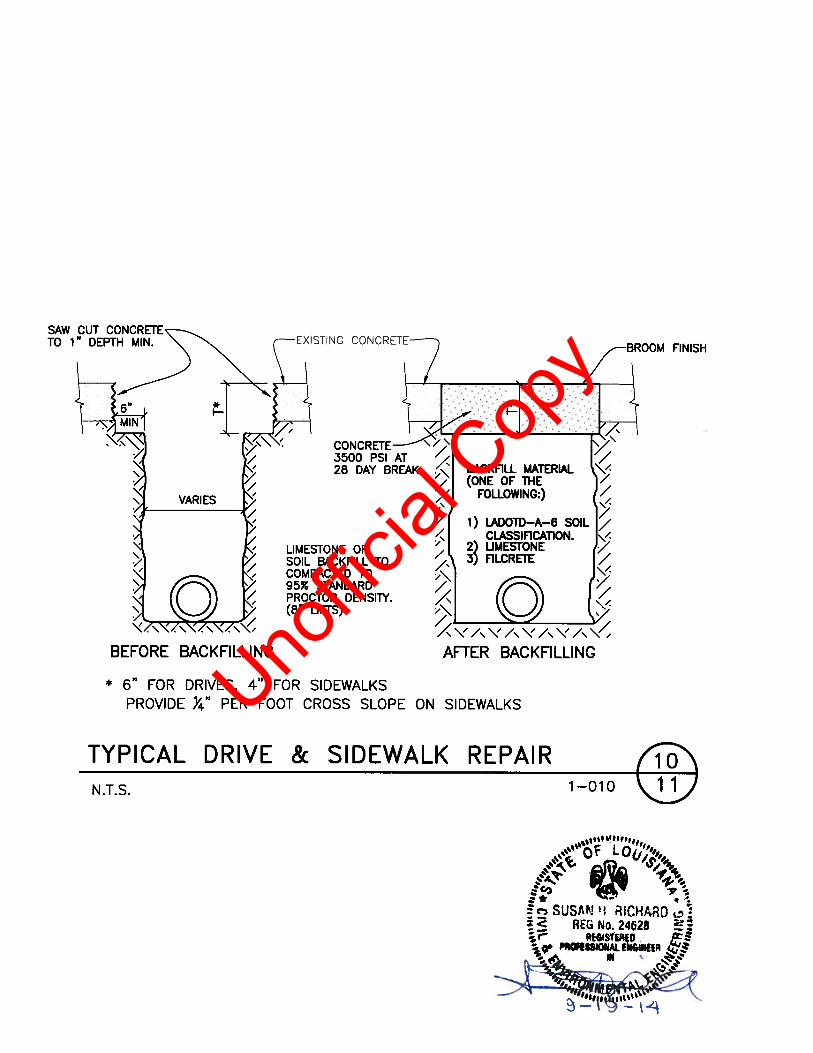
Item No. 5 REFER to the Plans, Sheet 11, Detail 10. Substitute the attached detail for this detail for
driveways and sidewalks. Item No. 6 REFER to the Specifications. DELETE the Division 16 – Electrical Specifications.
SUBSTITUTE the attached electrical specifications. Item No. 7 REFER to the Specifications. DELETE Section 02821 – Vinyl Fencing & Gates. The
fencing and gates on the project are wooden as called for on the plans. Received by: Signed: Dated: Company:
FAX THIS SIGNED PAGE TO DOMINGUE, SZABO & ASSOCIATES, INC. AT 337-237-7132; OR RESPOND TO EMAIL ACKNOWLEDGING RECEIPT OF ADDENDUM
End of Addendum No. 1
ABCD
Unoffic
ial C
opy
Unoffic
ial C
opy

SECTION 16000 - ELECTRICAL
SP50136.doc 1 08/12/14
DETAILED SPECIFICATION FOR
ELECTRICAL WORK
ARTICLE 1. GENERAL
The general conditions are a part of this specification and the Contractor shall consult them
in detail for instructions pertaining to his work. He shall also consult all other sections to
determine if any other work is to be performed.
All work shall be done in accordance with the National Electric Code and with local and
state ordinances governing this class of work.
ARTICLE 2. SCOPE OF WORK
The work covered by this section includes the provision of all labor and material required
to complete installation of the electrical system as indicated in the accompanying plans.
The work includes, but shall not be limited to the following:
provide and install all conduit, wiring, terminal blocks, enclosures, receptacles, conduit
seals, etc.;
install the control panel furnished by the pump supplier with motor starters, pump
alternators and level controls;
connect all electrical equipment;
provide and install aluminum support frames, Unistrut, brackets, and other mounting
materials;
provide and install all lighting fixtures, complete with lamps;
demolish and remove existing electrical equipment where called for in the plans;
provide and install all wiring, conduit, junction boxes, etc., for control wiring;
provide and install level control ultrasonic transducer, tip float switches and supporting
brackets.
All electrical equipment installed or connected by contractor shall be in strict accordance
with the instructions of the manufacturer.
This contractor is referred to the civil plans for information regarding details and
dimensions.
The contractor shall install his work to meet existing conditions as found at the site and
shall accommodate the work of other trades.
The electrical system as set forth herein is intended to be a working system which is in
Unoffic
ial C
opy
SECTION 16000 - ELECTRICAL
SP50136.doc 2 08/12/14
compliance with all required codes and standards; therefore, any discrepancy or omission
shall be reported prior to bidding.
ARTICLE 3. REFERENCES
Standards of the following organizations and the individual standards named shall be
followed as though they were part of this specification (unless otherwise noted):
Underwriters Laboratories (UL)
Southern Standard Building Code
State Fire Marshall's Act
The Institute of Electrical and Electronic Engineers
National Board of Fire Underwriters
National Electrical Code
National Electrical Manufacturers Association
Edison Electric Institute
Insulated Power Cable Engineers Association
American National Standards Institute
American Society for Testing Materials
National Electrical Safety Code
National Fire Protection Association
Applicable Rules and Regulations of the local
utility companies providing services
ARTICLE 4. REGULATORY REQUIREMENTS
Observe and comply with all applicable federal, state and local laws, municipal ordinances,
codes and the rules and regulations of all authorities having jurisdiction over construction
of the project.
Adhere to the following standards, where applicable.
NEMA ICS-1-1983 General Standards for Industrial Control and Systems
NEMA ICS-2-1983 Industrial Control Devices, Controllers and Assemblies
NEMA ICS-3-1983 Industrial Systems
NEMA ICS-4-1983 Terminal Blocks for Industrial Use
NEMA ICS-6-1983 Enclosures for Industrial Control and Systems
NFPA 70E Electrical Safety Requirements for Employee Workplaces
NFPA 79 Electrical Standards for Industrial Machinery
NFPA 328 Flammable and Combustible Liquids and Gasses in Manholes, Sewers and
Similar Underground Structures
NFPA 820 Standard for Fire Protection in Wastewater Treatment and Collection
Facilities
ANSI B 286-74 (R-1985) Copper Conductors for Use in Hookup Wire for Electronic
Equipment
IEEE 74-1958 Standard Test Code for Industrial Control
ISA RP60.1 Control Center Facilities
ARTICLE 5. HAZARDOUS AREAS
The contractor should be aware that certain areas of each pump station are considered
"hazardous" areas as defined in the National Electrical Code. Special wiring techniques,
Unoffic
ial C
opy

SECTION 16000 - ELECTRICAL
SP50136.doc 3 08/12/14
materials and equipment must be used in such areas. The contractor is referred to Articles
500 and 50l of the NEC for detailed requirements for electrical work in hazardous areas.
All equipment and material used in hazardous areas must be suitable for use in such areas.
ARTICLE 6. REJECTED WORK AND MATERIAL
Should the contractor introduce any materials different from that sort and quality described
in the specifications or shown on the plans, it must be immediately removed from the
premises when requested by the Engineer.
ARTICLE 7. ADDITIONS AND CHANGE
All electrical work is to be done in strict accordance with this specification and the
accompanying plans. Any alterations or changes in design or material without the
Engineer's prior approval and knowledge are prohibited.
ARTICLE 8. SHOP DRAWINGS
Shop drawings shall be submitted for the Engineer's approval prior to proceeding with the
work and within thirty (30) days of awarding of the contract. Included and in particular are
shop drawings for lighting fixtures, other electrical equipment and all other such drawings
as the Engineer may require. Review and approval of any drawings by the Engineer shall
not release the contractor from responsibility for errors and omissions in such drawings.
ARTICLE 9. STANDARDS OF MATERIALS AND WORKMANSHIP
All work shall present a neat and finished appearance when completed and shall be
executed in a workmanlike manner. All materials furnished by the contractor shall be new
and listed by the Underwriters' Laboratories (UL) as conforming to its standards.
Equipment shall meet NEMA standards wherever such standards have been established.
ARTICLE 10. GUARANTEE
Subcontractor for this work shall be required to keep the work installed by him in repair
and perfect working order for one (1) year from the date of final acceptance.
ARTICLE 11. MATERIALS AND PRIOR APPROVAL
The contractor shall base his proposal on materials as specified herein. Specific mention of
a manufacturer or trade name is not intended to indicate preference but to indicate a type
and standard of quality. However, any substitutions for materials specified herein must be
submitted to the Engineer for approval seven (7) days prior to the bid date.
ARTICLE 12. LAWS, PERMITS AND INSPECTIONS
This contractor shall at his own cost obtain necessary permits, pay all legal fees and
charges and comply with the state and municipal building and safety laws, ordinances and
regulations relating to building and public health and safety.
Unoffic
ial C
opy
SECTION 16000 - ELECTRICAL
SP50136.doc 4 08/12/14
ARTICLE 13. SAFETY PRECAUTIONS
The contractor shall furnish and place proper guards for prevention of accidents. He shall
provide and maintain any other necessary construction required to secure safety of life or
property. This requirement will apply 24 hours per day until acceptance of work by the
Owner and shall not be limited to normal working hours.
ARTICLE 14. SITE INSPECTION
The contractor shall visit the site and familiarize himself with the difficulties which may be
encountered in execution of the work.
ARTICLE 15. DOCUMENTATION
Three copies of all descriptive data, printed installation instructions, operating and
maintenance instructions and parts lists for each item of material or equipment supplied by
the contractor shall be delivered to the Engineer.
Shop drawings, descriptive data, printed installation instructions, operating and
maintenance instructions and parts lists shall be neatly bound in a hard-cover three (3) ring
binder and turned over to the Engineer before acceptance of the project.
ARTICLE 16. RECORD DRAWINGS
The contractor is to be provided with a set of drawings by the Engineer on which he is to
record any changes required as the result of unforeseen difficulties. The drawings shall be
submitted to the Engineer in good condition.
ARTICLE 17. WORK IN OTHER SECTIONS
The contractor is referred to other sections of these specifications for other work he may be
called upon to do and for additional requirements which apply to the equipment being
supplied.
ARTICLE 19. WIRING DEVICES
Toggle switches shall be Hubbell 1121-I (or equal).
Ground fault interrupter (GFI) type duplex receptacles shall be Hubbell #GF5362-I (or
equal).
All receptacles shall be installed in suitable outlet boxes, rigidly fastened to walls. All
wiring devices shall be installed in FS boxes and shall be provided with cast aluminum
snap covers suitable for wet locations. Hubbell #WPFS26 (or equal) for GFI receptacles
and Hubbell #7423WO (or equal) for toggle switches, shall be provided. Provide “in-use”
receptacle covers where called for in the plans.
ARTICLE 20. RACEWAYS AND FITTINGS
All conduit used above grade shall be galvanized rigid steel unless otherwise specified in
the plans. All conduit below grade shall be SCH 40 PVC. Convert below grade.
Unoffic
ial C
opy
SECTION 16000 - ELECTRICAL
SP50136.doc 5 08/12/14
Galvanized Rigid Steel Conduit: This conduit shall be galvanized inside and outside by the
hot-dip or electro-galvanize processes. (ANSI - C80.1 and UL-6).
PVC Conduit: This conduit shall be rigid schedule 40 or 80 PVC conduit rated 90oC and
UL listed. (NEMA TC 2 and UL-651).
All wiring is to be installed in raceways, except within the wet well.
All outdoor conduit connections from above to junction and pull boxes, conduit fittings,
outlets, disconnect switches, etc., must be watertight.
Raceways shall be supported by pipe straps, hangers, or other approved fastening or
support devices spaced not more than 8' apart with a minimum of two supports for each 10'
length.
Flexible metal conduit shall be weatherproof or explosion proof, as required and installed
in strict accordance with the provisions of Article 350 or 501 of the NEC.
ARTICLE 21. CONDUCTORS AND WIRING
All conductors are to be copper.
Circuit conductors shall have THW or THWN 600 V. insulation.
Conductors #8 and larger shall be stranded.
No conductors for power and lighting branch circuits shall be smaller than #12.
Conductors shall be color coded throughout the system. On larger conductors paint or tape
bands may be used.
ARTICLE 22. LIGHTING FIXTURES
New fixtures are to be thoroughly cleaned prior to installation and shall be furnished
complete with lamps. Refer to the plans for fixture types.
ARTICLE 23. CONDUIT SEALS
Conduit seals shall be furnished where called for in the plans. Seals shall be the type EYS
as manufactured by Appleton or Crouse-Hinds. Sealing compound shall be "Apelco" or
"Chico A".
ARTICLE 24. CONTROL PANEL AND LEVEL CONTROLS (BY PUMP SUPPLIER)
GENERAL: All electrical work shall be in accordance with the National Electrical Code.
Certain areas of the pump station are considered "hazardous" as defined in the National
Electrical Code and all equipment shall comply with NEC Article 50l. The motor
horsepower shown in the electrical plans is a minimum horsepower. All equipment and
wiring within the control panel shall be sized as required for the motors which are
Unoffic
ial C
opy
SECTION 16000 - ELECTRICAL
SP50136.doc 6 08/12/14
furnished under other sections of the specifications even though the motor horsepower is
greater than that show in the electrical plans.
ENCLOSURE: The control panel enclosure shall be NEMA-4X and tamperproof and shall
have a drip hood top. A resistance heater and thermostat shall be furnished to prevent
condensation in the enclosure. The door shall be hinged and gasketed. A means for
padlocking shall be provided. No switches or indicators shall be visible on the exterior
door but shall instead be mounted on an interior door which shall make the panel dead-
front. Switches and indicators shall be identified with engraved plastic nameplates or other
approved means.
POWER DISTRIBUTION: Electrical service to the control panel will be 240 volt, three-
phase, four-wire which will be fed from an adjacent fusible switch. Power shall be
distributed to each motor starter. Appropriate motor overload/overcurrent protection shall
be provided. A single-pole 120V 20-amp auxiliary power circuit breaker, a single-pole
120V 20-amp control power circuit breaker and a 120V 20-amp single-pole lighting circuit
breaker shall be provided. All circuit breakers shall have an interrupting capacity of at
least 10,000 amps RMS symmetrical. A properly sized main circuit breaker shall be
provided. The main breaker shall be interlocked with the interior door so that power must
be off for the door to be opened. A ground fault interrupter type auxiliary power receptacle
shall be provided within the enclosure.
PROTECTION: In addition to a circuit breaker for overload and short circuit protection,
the service entrance shall be provided with a lightning arrester and a surge suppressor.
Phase failure/unbalance and phase reversal protection shall be provided for the control
panel. Motors shall be protected by overload relays which are a part of the motor starters
and by the submersible pump heat sensors. A seal failure alarm shall also be provided for
each motor. Pumps shall not be stopped if a seal failure occurs.
MOTOR STARTERS: Circuit breaker type full voltage non-reversing motor starters shall
be furnished. Starters shall be equipped with a Class 20 electronic overload relay. Starters
shall meet NEMA standards. IEC starters will not be acceptable. Provide a Timemark
#2652 line voltage monitor relay (or equal) unless the solid-state overload protection
provides the equivalent (if so, set the starter for phase failure protection). Approved
manufacturers include Square "D", Cutler Hammer and Siemens; prior approval is required
for all other manufacturers.
ULTRASONIC LEVEL CONTROLS: An ultrasonic level controller shall be furnished
and installed through the control panel door so as to be visible with the inner door closed.
The unit shall be capable of sensing the liquid level in a sewage wet well. At least 5 contact
closures corresponding to levels shall be made available for use in controlling the pumps.
The ultrasonic transducer installation shall be in compliance with the NEC for hazardous
locations (Class 1 Division 2 Groups C and D). The unit shall operate at 120 VAC. All
required mounting hardware and accessories necessary to mount or install the transducer
where shown in the plans shall be provided. The level system shall be the MultiRanger
100/200 as manufactured by Milltronics. The ultrasonic transducer shall be the Milltronics
XPS 10F. (Or prior approved equal).
TIP FLOAT SWITCH LEVEL CONTROLS: Provide tip float switches for redundant
control of pump operation. The floats and cords shall be intended for use in raw sewage
wet wells. Refer to the plans for additional information and installation details. The tip
Unoffic
ial C
opy
SECTION 16000 - ELECTRICAL
SP50136.doc 7 08/12/14
float manufacturer shall be as requested by the Owner. Intrinsically safe relays shall be
provided for each discrete tip float switch input. The intrinsically safe relays shall be listed
for Class 1 locations. A "redundant off" tip float switch shall be provided connected to stop
the pumps and provide a low level alarm if the "all off" level control fails.
PUMP OPERATION: Pump operation shall be determined by either the tip floats or the
ultrasonic level system. A selector switch shall be provided for this purpose. H-O-A
switches shall be provided for both pumps. The pumps shall alternate automatically. A lag
pump time delay start shall stagger the restart of both pumps after a power outage. The
control circuitry shall be designed so that if a pump is taken out of service, the normal
sequence of operation shall be automatically interrupted and the disabled pump removed
from its position in the alternating sequence. The remaining pump shall then operate on
each successive cycle as the lead pump at the lead pump run level. When the disabled
pump is placed back in service, normal alternating operation shall automatically resume.
Should the lead pump fail on overload, the lag pump shall again operate at the lead pump
operating liquid level. The alternation of pumps must take place with both pumps off. A
lag pump time delay start is required to stagger the restart of both pumps after a power
outage. A manual override switch shall be provided to lockout the alternator and allow the
operator to select either pump as the lead.
CONTROLS, INDICATORS AND PILOT DEVICES: The following shall be provided on
the interior door for each motor: hand-off-auto switch, pump running pilot light, pump
overload pilot light, elapsed time meter, seal failure pilot light and manual reset switch.
Provisions for operation of red and green station status lights external to the control panel
shall be provided. The red light shall flash if a high or low level alarm or a motor overload
occurs. The green light shall be steady-on when either pump runs. The station status light
shall be the Federal Signal 191XL fixtures described in the plans. No other status light will
be acceptable.
SCADA: Provide a terminal strip in the control panel and wire the following I/O to the
strip.
1. Pump #1 running (dry contact closure)
2. Pump #2 running (dry contact closure)
3. Pump #1 in auto (dry contact closure)
4. Pump #2 in auto (dry contact closure)
5. Pump #1 seal fail (dry contact closure)
6. Pump #2 seal fail (dry contact closure)
7. Pump #1 overload/fail (dry contact closure)
8. Pump #2 overload/fail (dry contact closure)
9. High level alarm (dry contact closure)
10. Low level alarm (dry contact closure)
11. Wet well level (4-20ma from the Milltronics unit)
12. 5 spare positions
WIRING: All power and control wiring shall be stranded copper type MTW. All wires
shall be marked at each point of termination with self-adhering wire markers with the same
designation used on the wiring schematic. All wires shall be routed in plastic Panduit
wireways. All points necessary for external connection in the control panel, whether
power or control, shall be wired to a terminal strip located at the top or bottom of the
enclosure as required. The terminal strip shall be permanently marked with the same
Unoffic
ial C
opy
SECTION 16000 - ELECTRICAL
SP50136.doc 8 08/12/14
designation as the wire connected to it. All circuit breakers, starters, and other control
devices mounted within the control panel shall be labeled for identification, both within the
panel and on the wiring schematic with corresponding designations. A power diagram,
control schematic and parts list shall be permanently affixed to the inside of the enclosure
door.
SHOP DRAWINGS: Submit shop drawings for the control panel and level control
equipment.
MISCELLANEOUS: The control panel manufacturer shall be actively engaged in the
design and fabrication of this type of equipment. The manufacturer shall have at least 5
years experience in sewage pump controls. The manufacturer shall furnish six copies of
enclosure details, deadfront layouts, nameplate details, scaled interior layouts, power
diagrams, control schematics, complete material lists and indexed catalog data for
Engineer's approval prior to fabrication of control equipment.
ARTICLE 25. IDENTIFICATION
All wires shall be marked at each point of termination with self-adhering wire markers
with the same designation used on the pump control panel schematic.
ARTICLE 26. CONCRETE
Where concrete is required it shall be 3000 psi minimum (standard aggregate) and shall be
in accordance with ACI standards. All reinforcing (if required) shall be in accordance with
ASTM A615(GR40).
ARTICLE 27. PADLOCKS
Padlocks shall be provided for the transfer switches, disconnect switches and control
panels which are installed outdoors and are subject to unauthorized entry. All padlocks
shall be keyed to match existing locks. Verify with Owner. Four keys shall be furnished to
the Owner.
ARTICLE 28. START-UP AND TESTING
After completion of the work the contractor shall conduct an operating test for approval in
the presence of the Engineer or his representative. At this time, it shall be demonstrated
that the equipment operates in accordance with this specification.
The Contractor shall accurately measure the current of each phase of each pump
motor, while the pump is in operation and pumping water. Measure the currents
using a clip-on ammeter on each phase in rapid succession, so that the pump motor
load will be approximately the same for each reading. The readings shall be
submitted to the Engineer.
The Contractor shall record the nameplate horsepower, starting code letter and full
load current of each pump motor and shall submit the information to the Engineer.
Record the part number and setting of the overload relays. This information shall be
submitted to the Engineer.
Unoffic
ial C
opy

SECTION 16000 - ELECTRICAL
SP50136.doc 9 08/12/14
The contractor shall instruct the Owner's operating personnel during start-up and separate
operating tests of each major item of equipment.
ARTICLE 29. PAYMENT
Payment for electrical work shall be as outlined elsewhere in the specifications.
Unoffic
ial C
opy