Copper Tube in Domestic Water Services
36
COPPER TUBE IN DOMESTIC WATER SERVICES COPPER TUBE IN DOMESTIC WATER SERVICES DESIGN AND INSTALLATION DESIGN AND INSTALLATION COPPER DEVELOPMENT ASSOCIATION PUBLICATION 33 COPPER DEVELOPMENT ASSOCIATION PUBLICATION 33
Transcript of Copper Tube in Domestic Water Services
C O P P E R T U B E I N D O M E S T I CWAT E R S E RV I C E S
C O P P E R T U B E I N D O M E S T I CWAT E R S E RV I C E S
D E S I G N A N D I N S TA L L AT I O ND E S I G N A N D I N S TA L L AT I O N
C O P P E R D E V E L O P M E N T A S S O C I AT I O NP U B L I C AT I O N 3 3
C O P P E R D E V E L O P M E N T A S S O C I AT I O NP U B L I C AT I O N 3 3
C O P P E R T U B E I N D O M E S T I C W A T E R S E R V I C E S
D E S I G N A N D I N S T A L L A T I O N
COPPER TUBE IN DOMESTIC WATERSERVICESDESIGN AND INSTALLATION
CDA Publication 33, December 1999.
MEMBERS, as at 1st January 2000
ASARCO International
Thomas Bolton Copper Products Ltd
Codelco Services Ltd
IMI plc
Rio Tinto London Ltd
Boliden MKM Ltd
British Non-Ferrous Metals Federation
Gecamines
Noranda Sales Corporation of Canada Ltd
Southern Peru Copper Corp
Copper Development Association (limited by guarantee)is a non-trading organisation sponsored by the copperproducers and fabricators to encourage the use ofcopper and copper alloys and to promote their correctand efficient application. Its services, which include theprovision of technical advice and information, areavailable to those interested in all aspects of existing andpotential uses of copper. The Association also providesa link between research and the user industries andmaintains close contact with other copper developmentorganisations throughout the world.
Designed, produced and printed by Sacombe press Limited
Copper Development AssociationVerulam Industrial Estate224 London RoadSt. AlbansHertsAL1 1AQ
Telephone: 01727 731200Facsimile: 01727 731216Websites: www.cda.org.uk
www.brass.org

C O P P E R T U B E I N D O M E S T I C W A T E R S E R V I C E S
D E S I G N A N D I N S T A L L A T I O N
i
1 I n t r o d u c t i o n 1
1.1 Advantages of copper tube 1
2 C o p p e r Tu b e s 1
2.1 Maximum working pressure 22.2 Chemical Composition 2
3 F i t t i n g s 2
3.1 Lead-free solders 33.2 Joining dissimilar metals 3
4 D e s i g n C o n s i d e r a t i o n s 4
4.1 Water velocities 44.2 Pipe layout 44.3 Protection of piping 44.4 Underground services 54.5 Expansion joints 54.6 Fixings 54.7 Air locks and water hammer 64.8 Services embedded in concrete 64.9 Thermal insulation 6
5 J o i n t i n g M e t h o d s 7
5.1 Compression joints 75.2 Capillary joints 75.3 Push-fit fittings 85.4 Press-fit fittings 85.5 General procedure for all fittings 8
5.5.1 Measuring 85.5.2 Cutting to length 85.5.3 Deburring of tube ends 85.5.4 Re-rounding of tube ends 85.5.5 Jointing plastics coated copper tube 9
5.6 Detailed procedures for capillary fittings 95.6.1 Cleaning 95.6.2 Fluxing 95.6.3 Assembling 95.6.4 Heating 95.6.5 End feed fittings 9
6 B e n d i n g C o p p e r Tu b e 10
6.1 Bending by machine 106.2 Distortion of tube in machine-made bends 106.3 Steel springs 10
7 C o m m i s s i o n i n g 10
7.1 General site operations 11
A p p e n d i x A - P i t t i n g C o r r o s i o n o f C o p p e r Tu b e s 11
A1 Carbon Film 11A2 Hot, soft water 11A3 Flux 11

C O P P E R T U B E I N D O M E S T I C W A T E R S E R V I C E S
D E S I G N A N D I N S T A L L A T I O N
ii
A p p e n d i x B - C o n d i t i o n s o f w a t e r 11
B1 Water mains 12B2 Condition of water 12B3 Treatment of acid waters 12
A p p e n d i x C - D e z i n c i f i c a t i o n R e s i s t a n t B r a s s 12
C1 Waters causing dezincification 12
A p p e n d i x D - C a l c u l a t i n g Tu b e T h i c k n e s s 13
A p p e n d i x E - C o p p e r a n d L e g i o n n a i r e s ’ D i s e a s e 13
A p p e n d i x F - Ve n t e d & U n v e n t e d D o m e s t i c H o t Wa t e r S y s t e m s 14
F1 Pipe sizing 14F2 Cold water feed pump 14F3 Open vent pipe 14F4 Hot water storage vessels 15F5 Direct systems 15F6 Indirect systems 15F7 Vented primary circuit 15F8 Sealed primary circuit 15F9 Secondary distribution systems 15F10 Minimum distribution pipe sizes 15
A p p e n d i x G - P r e f r a b r i c a t e d C o p p e r P i p e w o r k 15
G1 Benefits 16G2 Specialist equipment 16G3 Wider applications 16
A p p e n d i x H - Wa t e r F l o w R e s i s t a n c e 17
A p p e n d i x I - R e g u l a t i o n s a n d S t a t u t o r y R e q u i r e m e n t s 23
R e f e r e n c e s 23
TextBritish and European Standard SpecificationsOther referencesOther sources of information
TablesTable 1 Dimensions for tube to BS EN 1057Table 2 Design stress values for 65˚CTable 3 Design stress values for temperatures in
excess of 110˚CTable 4 Maximum temperatures and pressures for
capillary joints using tin/silver, tin/coppersolder
Table 5 Maximum working temperatures andpressures for compression joints
Table 6 Galvanic series for metal and alloysTable 7 Spacing for Copper Tube SupportsTable 8 Maximum lengths of un-insulated distribution
pipesTable 9 Minimum distribution pipe sizes
FiguresFigure 1 Compression fittingFigure 2 Integral solder ring capillary fittingFigure 3 End feed capillary fittingFigure 4 Large diameter compression couplingFigure 5 Horseshoe and loop expansion jointsFigure 6 Bellows expansion jointsFigure 7 Gland type expansion jointFigure 8 FixingsFigure 9 Method of fixing long lengths of pipework
along a wall (Sliding expansion joint)Figure 10 Method of fixing long lengths of pipework
along a wall (Loop expansion joint)Figure 11 Indirect unvented (vented primary) systemFigure 12 Indirect unvented (sealed primary) systemFigure 13 Direct (vented) systemFigure 14 Indirect (vented) system

C O P P E R T U B E I N D O M E S T I C W A T E R S E R V I C E S
D E S I G N A N D I N S T A L L A T I O N
1
This publication brings together basic information on awide range of applications of copper tube in domesticwater services. The majority of copper tubes and fittingsavailable today have been developed over the past sixtyyears for use in hot and cold water services. During thatperiod smaller diameter and thinner wall tubes havebeen introduced and the number of applications hasincreased significantly. New uses include residential firesprinkler systems. This publication does not set out to bea detailed design guide but rather to give basicinformation on the range of actual and potentialapplications for copper tube in domestic water services.A companion publication entitled ‘Copper in DomesticHeating Systems’, publication 39, covers the use ofcopper in a number of forms and products in a widerange of domestic central heating systems.
The purpose of this publication is to assist the architect,designer and specifier as well as the operator in theunderstanding of the correct use of copper and copperalloys in domestic water service systems. Unvented hotwater systems and regulations concerning standards ofwater quality together with the incidence and dangers ofLegionnaires’ Disease have highlighted the potentialadvantages of copper in domestic water services.
It should be noted that corrosion problems haveoccasionally arisen in certain soft water installations inthe United Kingdom and elsewhere. In the rare
instances where problems have occurred these can beattributed to a combination of effects, including changesin the water supply, defects in design, incorrectinstallation techniques and failures to observerecommended commissioning and maintenanceprocedures. This publication therefore gives generalguidance on good practices to reduce the potentialincidence of the various forms of corrosion that mayoccur.
1.1 Advantages of copper tubeThe properties that make copper tube the preferredmaterial for domestic water services include thefollowing:
➤ ease of installation➤ ability to be easily joined and manipulated ➤ high strength➤ high ductility➤ ease of fabrication➤ corrosion resistance➤ suitability for use with potable and other
waters ➤ potential as bactericide➤ bio-fouling resistance➤ availability in a range of metric sizes
compatible with fittings and other systemcomponents
➤ guaranteed British Standard quality products
1 I n t r o d u c t i o n
2 C o p p e r Tu b e s
Copper tubes for domestic water services should bemanufactured to BS EN 1057. This specification coversa range of sizes with appropriate tempers and wallthicknesses to meet a wide range of servicerequirements and conditions. Tubes to BS EN 1057 are
specifically designated for water and gas in sanitary andheating applications and meet the requirements of BS6700. Annealed tube is designated BS EN 1057 - R220and half-hard tube is designated BS EN 1057 - R250.
Wall thickness, mm0.6 0.7 0.8 0.9 1.0 1.2 1.5 2.0 2.5
ODmm681012152228354254
66.776.1108133159
W X YW X Y
X W YX Y
X YX YX Y
X YX YX YX Y
X YX YX
XNOTE: BS EN 1057 specifies copper tubes which were available in BS 2871 Part 1. W - indicates BS 2871:Part 1 Table W tube sizeX - indicates BS 2871:Part 1 Table X tube size Y - indicates BS 2871:Part 1 Table Y tube size
Table 1 Dimensions for tube to BS EN 1057

C O P P E R T U B E I N D O M E S T I C W A T E R S E R V I C E S
D E S I G N A N D I N S T A L L A T I O N
2
2.1 Maximum working pressuresThe maximum working pressures at temperatures up to65oC are calculated using the following formula:
P = 20FtD-t
Where P = maximum working pressure (bar)F = design stress (N/mm2)t = minimum wall thickness (mm)D = maximum outside diameter (mm)
Tubes installed underground, laid under floors or inother inaccessible places must be able to withstandtwice the maximum working pressure.
The values of F used in the above formula depend uponthe condition of the tube and are given in Table 2.
Table 2 Design stress values for 65oC
Tubes in the 1/2H and H condition locally annealedduring fabrication e.g. during hot bending, silverbrazing or the attachment of welded fittings, shouldhave the working pressure calculated from the designstress F in the annealed condition. Certain largediameter and/or thick walled copper tubes may be
subjected to over annealing during fabrication. This mayresult in the design strength being below that quoted forthe annealed condition. If in doubt in thesecircumstances the customer should seek advice from thetube manufacturer.
Design stress values (F) for copper tubes operating attemperatures in excess of 110oC up to a maximum of200oC are given in BS 1306 and typical values for tubein the annealed condition are given in Table 3.
Table 3 Design stress values for workingtemperatures in excess of 65oC
Values for intermediate temperatures may beinterpolated as required.
2.2 Chemical compositionThe chemical composition of copper tubes to BS EN1057 shall conform to the following requirements:
Cu + Ag: min. 99.90%
0.015% < P < 0.040%
Grade of copper designated Cu-DHP or CW024A.
3 F i t t i n g s
Various jointing techniques using either compression(Figures 1 & 4), capillary (Figures 2 & 3) methods orpush-fit fittings are available. They employ gunmetal,brass (including dezincification resistant brass - seeAppendix C) and wrought copper fittings in sizes up to67mm, compression and capillary fittings beingmanufactured to BS EN 1254. Fittings of 67mm andlarger are generally considered to be specialist andreference should be made to the tube and fittingsmanufacturers. Flanges and bolting to BS 4504: Part 2are available for larger size copper tube. Copper tubemay also be brazed and welded either directly or bymeans of copper or copper alloy weld fittings. The most
common methods for joining copper tubes involve theuse of the following:
Compression Fittings Type A - Non-manipulativeType B – Manipulative
Capillary Fittings Soft Solder - End FeedIntegral Solder Ring
Push-fit Fittings
High Duty Fittings Silver Brazing - End FeedIntegral Brazing Ring
Table 4 Maximum working temperatures and pressures for capillary joints using tin/silver, tin/copper solder.
Condition F(N/mm2)Annealed O, R220Half-hard 1/2H, R250Hard H, R290
4660
72.5
Temperature oCMax. admissable stressfor annealed, R220,condition, N/mm2
40 34 26 18
110 150 175 200
Maximum Temperature(oC)
From 6mm up to &including 34mm
Over 34mm up to &including 54mm
Over 54mm up to &including 108mm
3065110
25 bar25 bar16 bar
25 bar16 bar10 bar
16 bar16 bar10 bar
C O P P E R T U B E I N D O M E S T I C W A T E R S E R V I C E S
D E S I G N A N D I N S T A L L A T I O N
3
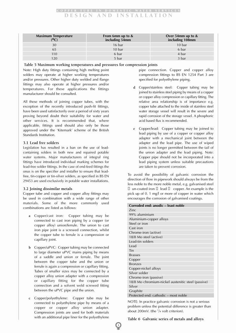
Note: High duty fittings containing high melting pointsolders may operate at higher working temperaturesand/or pressures. Other higher duty welded and flangefittings may also operate at higher pressures and/ortemperatures. For these applications the fittingsmanufacturer should be consulted.
All these methods of joining copper tubes, with theexception of the recently introduced push-fit fittings,have been used satisfactorily over a period of sixty yearsproving beyond doubt their suitability for water andother services. It is recommended that, whereapplicable, fittings used should also only be thoseapproved under the ‘Kitemark’ scheme of the BritishStandards Institution.
3.1 Lead free soldersLegislation has resulted in a ban on the use of lead-containing solders in both new and repaired potablewater systems. Major manufacturers of integral ringfittings have introduced individual marking schemes forlead-free solder fittings. In the case of end-feed fittings theonus is on the specifier and installer to ensure that lead-free, tin-copper or tin-silver solders, as specified in BS EN29453 are used exclusively in potable water installations.
3.2 Joining dissimilar metalsCopper tube and copper and copper alloy fittings maybe used in combination with a wide range of othermaterials. Some of the more commonly usedcombinations are listed as follows:
a Copper/cast iron: Copper tubing may beconnected to cast iron piping by a copper (orcopper alloy) union/ferrule. The union to castiron pipe joint is a screwed connection, whilstthe copper tube to ferrule is a compression orcapillary joint.
b Copper/uPVC: Copper tubing may be connectedto large diameter uPVC mains piping by meansof a saddle and union or ferrule. The jointbetween the copper tube and the union orferrule is again a compression or capillary fitting.Tubes of smaller sizes may be connected by acopper alloy union adapter with a compressionor capillary fitting for the copper tubeconnection and a solvent weld screwed fittingbetween the uPVC pipe and the union.
c Copper/polyethylene: Copper tube may beconnected to polyethylene pipe by means of acopper or copper alloy union adapter.Compression joints are used for both materialswith an additional pipe liner for the polyethylene
pipe connection. Copper and copper alloycompression fittings to BS EN 1254 Part 3 arespecified for polyethylene piping.
d Copper/stainless steel: Copper tubing may bejoined to stainless steel piping by means of a copperor copper alloy compression or capillary fitting. Therelative area relationship is of importance e.g.copper tube attached to the inside of stainless steelwater storage vessel will result in the severe andrapid corrosion of the storage vessel. A phosphoricacid based flux is recommended.
e Copper/lead: Copper tubing may be joined tolead piping by use of a copper or copper alloyadapter with a mechanical joint between theadapter and the lead pipe. The use of wipedjoints is no longer permitted between the tail ofthe union adapter and the lead piping. Note:Copper pipe should not be incorporated into alead piping system unless suitable precautionsare taken to prevent corrosion.
To avoid the possibility of galvanic corrosion thedirection of flow in pipework should always be from theless noble to the more noble metal, e.g. galvanised steel→un-coated iron → lead → copper. An example is thepick up of 0. 1 mg/l or more of copper in water whichencourages the corrosion of galvanised coatings.
Table 5 Maximum working temperatures and pressures for compression joints
Maximum Temperature(oC)
From 6mm up to &including 54mm
Over 54mm up to &including 108mm
3065110120
16 bar10 bar6 bar5 bar
10 bar6 bar4 bar3 bar
NOTE: In practice galvanic corrosion is not a seriousproblem unless the potential difference is greater thanabout 200mV. (the 1/4 volt criterion).
Table 6 Galvanic series of metals and alloys
Corroded end: anodic – least nobleZinc99% aluminiumAluminium-copper alloysSteel or ironCast ironChrome-iron (active)18/8 Mo steel (active)Lead-tin soldersLeadTinBrassesCopperBronzesCopper-nickel alloysSilver solderChrome-iron (passive)18/8 Mo chromium-nickel austenitic steel (passive)SilverGraphiteProtected end: cathodic – most noble
C O P P E R T U B E I N D O M E S T I C W A T E R S E R V I C E S
D E S I G N A N D I N S T A L L A T I O N
4
4 Design ConsiderationsDetailed layout and pipe sizing requirements aredetermined by the design engineer responsible for thesystem. General notes for guidance bringing out some ofthe points that have proved important in practice aregiven in the following sections. Users of this publicationshould ensure compliance with such statutoryrequirements, rules and regulations as may beapplicable to the particular installation, includingBuilding Regulations and British Standard SpecificationBS 6700.
4.1 Water velocitiesProblems can arise due to excessive water velocitieswhich in extreme conditions can cause prematurefailure by one of several mechanisms includingerosion/corrosion and/or cavitation. The maximumrecommended water velocity in copper cold waterservice pipes, irrespective of outside diameter, is 3 m/s,and for hot water recirculating systems 1.5 m/s. If thepipe diameter initially chosen gives a design velocitygreater than that recommended above, an appropriatelarger diameter pipe should be used. Pipes should besized to ensure that the maximum design flow ratesgiven in BS 6700 do not result in excessive watervelocities in copper tubes. It is important to recognisethat sluggish flow, at velocities below 0.5 m/s,associated with the over-sizing of pipework, especiallyin long horizontal runs may also cause problemsresulting from the deposition of detritus. This may resultin pitting corrosion, especially in the lower segments ofthe tube. Good design and operation is needed to avoidthese possible problems. There is also a possibility ofcorrosion occurring in pipework running only partiallyfilled. Cavitation may occur immediately followingrapid changes in cross-section, such as within outletfittings and this will also result in noise which can bereduced by lowering the pressure and hence the watervelocity.
Note: Water flow resistance data for tubes and fittingsare given in Appendix H
4.2 Pipe layoutAn important objective, particularly in large andcomplex installations, is to avoid, where possible, piperuns where stagnant or semi-stagnant conditions prevailfor long periods. With some types of water suchconditions tend to encourage the pick-up of tracequantities of metals, including copper, which can beavoided if there is a regular flow of water at reasonablevelocities through the pipes.
Measures to reduce such problems include thefollowing:
a Vertical riser or drop systems should beconsidered for use rather than a horizontal
distribution system. In addition ring type mainsincorporating short vertical risers will reducestagnant areas.
b There should be an adequate number and size of‘washout’ valves on the underground mainsupply and also on the internal systems at thebottom risers.
c Drinking water pipework should be sized for theminimum practicable diameter but withvelocities not exceeding 3 m/s.
d Direction of the pipe ‘fall or rise’ should beindicated on the installation drawings, withparticular attention paid to eccentric reducers onend reduction tees. Branch connections fromhorizontal mains should be taken off the top orbottom as appropriate to ensure correct airventing and complete draining of the system onemptying.
e Separation of fire-fighting hose reel and drinkingwater supplies is essential.
f Where necessary, cold water services should beinsulated to avoid undue pick-up of heat, e.g.from adjacent hot water pipes. Alternatively theyshould be installed below hot water pipes.
g Any part of a system intended to be used onlyintermittently should be fitted with isolatingvalves as well as drain valves installed at thelowest point.
h Long branch main lines supplying only isolatedor little used services should be avoided.
i Dead end lines or vertical drops to outlets thatare rarely used can be sources of problems whensedimentary matter settles out in stagnant water.
4.3 Protection of pipingProtection against frost damage is essential by use ofadequate insulation. This is particularly important inventilated and unheated roof spaces, and similarunheated and/or draughty locations. The followingprecautions should be taken in the laying and fixing ofcold water services:
1 Underground pipes should be buried at least 750mm and not more than 1350mm undergroundwhere practicable. This does not apply to pipesinstalled in the ground under permanentbuildings or structures.
2 Service pipes protected by ferrules to the top ofthe main should be taken into the building at the
4 D e s i g n C o n s i d e r a t i o n s

C O P P E R T U B E I N D O M E S T I C W A T E R S E R V I C E S
D E S I G N A N D I N S T A L L A T I O N
5
same depth underground by use of a ‘swan’sneck’ and if un-insulated should rise verticallywithin the building at least 750mm from theoutside wall.
3 The rising main to the storage cistern should becarried up on a warm inner wall, not inside acavity wall.
4 If outside pipes have to be installed aboveground they should be adequately insulated anddraw-off points provided to drain down theexposed pipes in frosty weather. The draw offpoint should be installed above ground toprevent contamination. Insulation by itself willnot prevent the freezing of water filled pipeworkover a period of time hence the need for draindown facilities. The only safe alternative is toprovide trace heating in the absence of heatedbuilding protection.
Some manufacturers of rigid phenolic foaminsulation materials recommend that a moisturebarrier be installed at the tube/lagging interface.Moisture between the tube and the lagging maylead to external corrosion of the copper tube.When using rigid phenolic foam insulationreference should always be made to themanufacturers installation instructions.
4.4 Underground servicesWhen copper pipework is installed underground it shallbe to BS EN 1057 (formerly BS 2871: Part 1 Table Y) andunless the soil or building materials are known to benon-aggressive, it is advisable to protect the outersurface of the tube by means of a factory applied plasticcoating or suitable water proof wrapping. Undergroundservices shall not be laid in contact with contaminatingmaterials such as foul soil, or passing through any sewer,drain or cesspool. In some areas the Water Authoritiesmay specify that the copper tube is externally coatedwith a factory applied polyethylene coating. In additionall copper alloy fittings installed underground shall bedezincification resistant, to specification BS EN 12164,BS EN 12165 or BS EN 12167 material designationCW602N, (formerly CZ132), or dezincificationimmune, such as gunmetal. Compression fittings shallbe of the manipulative type to BS EN 1254 Part 2 TypeB. Precautions should be taken to minimise the effects ofground movement on pipes and fittings buriedunderground. Where relative movement between themain and service pipes is anticipated the connectionshould be made with a flexible joint. Pipes passingthrough walls from unstable ground should be fittedwith telescopic joints and to maintain gradients towardswashouts and air vents supports should be providedfrom stable foundations. Pipes should be firmlyanchored at bends to withstand thrust loads and shouldbe capable of meeting a test pressure of twice themaximum working pressure.
4.5 Expansion jointsThe coefficient of thermal expansion of copper is 16.8 x10⁻⁶ per o C, hence a 1 metre length of copper tubebecomes (1+0.0000168T) metre when heated by To C.For example, an increase in temperature of 60o C willincrease the length by one mm for every metre of tube.In the case of copper tube in domestic hot water andheating installations the limited size of rooms and hencestraight pipe runs, together with the many bends andoffsets that normally occur will result in thermalmovement being accommodated automatically.However where long straight pipe runs, exceeding 10m, are encountered, allowance for expansion should bemade. Suitable types of expansion joint are shown inFigures 5, 6 and 7.
Expansion bellows and expansion loops may beaccepted with regard to the expansion of pipes carryinghot water. Where copper tubes pass through walls,floors and ceilings, they should be able to move as aresult of expansion and contraction. This can bearranged by passing the tube through a sleeve or lengthof larger diameter pipe fixed through the wholethickness of the wall, floor or ceiling, or by means offlexible joints on either side of the wall.
4.6 FixingsAll pipework should be adequately supported. There arevarious types of fixing clips and brackets to meetspecific requirements. A few of the fixings available areshown in Figure 8 but a greater selection is illustrated inmanufacturers’ catalogues and this information will helpto decide the most appropriate pattern.
Suitable intervals for pipe supports are given in Table 7.
Size of Pipe(OD)mm
Intervals forVertical Runs
mm
Intervals forHorizontal Runs
mm
68
1012
15.022.028.035.042.054.067.076.1
108.0133.0159.0
0.60.91.21.51.82.42.43.03.03.03.63.63.63.64.2
0.40.60.81.01.21.81.82.42.42.73.03.03.03.03.6
Table 7 Spacing for Copper Tube Supports

C O P P E R T U B E I N D O M E S T I C W A T E R S E R V I C E S
D E S I G N A N D I N S T A L L A T I O N
6
Bracing should not be at less than 12 m centres to avoidswaying when pipes are fixed by hanging brackets insuspended ceiling spaces. The distance between anchorfixings and expansion joints in hot water lines isdetermined by the type of joint used and the amount ofmovement within the joint itself. Figures 9 and 10 showhow a pipe run should be anchored by means of twosupports at each change of direction, with an expansiondevice in the centre. If the expansion joint has a 25 mmdepth of socket (Figure 9) then the length of pipeworkeach side of the joint, with a temperature difference of60o C can be 12.5 m (1 mm of movement within theexpansion joint permits 1 m of pipe length between jointand anchor point). In order to avoid possible breakdownof branch joints connected to a heating or hot water main,it may be advisable to use the branch joints as anchorfixings. If however the branch is connected to the movingpipe the leg of the branch should be free to move. Suitablepads should be inserted between the pipe and clip toavoid abrasion due to thermal movement. All pipe runsshould be aligned correctly to prevent undue strain. Thisis particularly important when fixing pipes to a plasticcistern. Suitably protected backing plates or washerswithout sharp edges should be fitted at the connectionpoints between the pipes and the cistern.
4.7 Air locks and water hammerAir locks can be prevented by the design and installationof systems to facilitate the removal of air during filling andsubsequent operation. Pipes should have a slight rise to acistern, vent pipe or an automatic air release valve alongtheir complete length and should wherever possible fall tothe drain-off points. Pipes should be laid to avoidobstructions and across solid foundations to prevent localundulations causing airlocks. Excessive pressure rises inpipework can lead to premature failure of joints andpossible damage to fittings. If unacceptable water hammeroccurs in a system due to the installation and operation offittings and appliances suitable measures should be takento limit the resultant pressure rises or surges. This can beachieved by fitting air or gas loaded vessels or specialmechanical water hammer preventers.
4.8 Services embedded in concreteCopper has excellent resistance to corrosion by potablewaters and is not attacked by normal types of cement,concrete or plaster. However, it should not be broughtinto contact with acid plasters, acid cements or cokebreeze. Cement additives such as foaming aminesshould not be allowed to come into contact withunprotected copper tube, nor cleaning fluids which maypermeate through screeds to embedded copper pipesbeneath. The installation of tubes and fittings embeddedwithin solid walls or floors is precluded except where itmay be readily exposed, or alternatively if installed in asleeve or duct which may be readily removed orreplaced.
Annealed copper in domestic hot water systemapplications is strong enough to withstand the
compressive stresses set up since the coefficient ofexpansion of concrete is less than that of copper. Thatapplies when the temperature of the water circulating inthe embedded pipes does not exceed 60o C providedthat the straight line pipe runs between embedded fixingpoints do not exceed about 15 m in length. In suchcases no problems arise if the copper pipe is laid on theconcrete base and covered with a sand and cementscreed provided that access is provided.
Pipes conveying water at temperatures above 60o Cparticularly if there are any branch connections, must begiven facilities within the solid structure for thermalmovement. Small diameter pipes (6 to 10 mm) can belaid directly on the concrete base in a snake-like patternand should be plastic sheathed, or similarly covered, toavoid adhesion of the final screed to the metal pipe.Larger diameter pipes (12 to 28 mm) should be laid inpurpose-made ducts not less than 50 mm wide and 100mm deep. If insulating material is used it should be of awater repellent type. The insulated pipework within theducts should then be covered with dry sand or similar toabout 25 mm above the top of the insulation. If the piperun exceeds 10 m in length, suitable expansion jointswith permanent access points should be fitted. Pipes inexcess of 35 mm in diameter should be installed inaccessible ducts, being suitably clipped or alternativelysupported on roller fixings with horseshoe brackets atevery 10 m to avoid the pipe jumping from the rollers.
4.9 Thermal insulationConsideration should be given to conserving energy byuse of suitable thermal insulation for pipes conveyinghot water. A range of factory insulated copper pipes areavailable from the major manufacturers. In additionsupply pipes containing cold water for domesticpurposes should be installed so that, as far as isreasonably practical, the water will not be warm whendrawn from the tap. If the cold supply cannot beinstalled away from hot water pipes or other sources ofheat then it should be adequately insulated. If neither ofthese measures are practicable then the cold pipeshould be installed below the hot pipe. This requirementshould not conflict with the need to provide adequateinsulation and/or a source of heat to provide frostprotection in otherwise unheated locations.
Frost protection can be achieved by means of traceheating cables attached to insulated pipework inexposed locations. Where pipes and/or fittings cannotbe positioned to provide adequate protection then theyshould be insulated and provided with a means ofdraining. If installed outside a building the insulationshould be weatherproof. Generally these outsideinstallations will be required to be fitted with a servicingand a draining valve inside the building.
Details of the recommended sizes and performance ofthermal insulating materials to BS 5422 and BS 3958 arecontained in BS 6700. It should be appreciated that

C O P P E R T U B E I N D O M E S T I C W A T E R S E R V I C E S
D E S I G N A N D I N S T A L L A T I O N
7
smaller diameter pipes require a proportionately greaterthickness of insulation. Adequate space should beallowed around tube fixings for the required thickness ofinsulation to be added after installation. Whereverpossible the insulation should be continuous over tubeand fittings but allowing access to valves for operation.Air spaces between pipework and the insulation willimprove the overall insulating properties of the insulatedpipework. The insulating material should be resistant toor protected by suitable covering from mechanicaldamage, ingress of moisture, and vermin. In the case ofinsulated tubing to be installed underground it shouldalso be water proof and resistant to attack by anycorrosive chemicals within the subsoil.
In the case of factory insulated copper tubing
manufacturers recommend procedures for insulatingjoints and fittings and for the removal and replacementof insulation during the jointing process. Data isavailable on the performance of factory insulatedcopper tube under different operating conditions.Additional advantages of factory insulated copper tubeinclude the reduction in water flow noise, high qualityappearance and surface finish, with no paintingrequired and improved safety due to low surfacetemperatures when carrying hot water. Insulated coppertube sheathed with an internally castellated plasticcoating traps an air layer to give improved insulationperformance. The colour coding of pipework should beblue for water and yellow for gas. It should be noted thatwhite insulated copper tube is generally supplied forexposed central heating system pipework.
5 J o i n t i n g M e t h o d s
The manufacturers of fittings for copper tubes provideliterature describing their products and full instructionson the use of their fittings. This literature should alwaysbe consulted by the user, but the following notes areincluded for general guidance.
5.1 Compression fittingsType ‘A’ non-manipulative compression fittings to BS EN1254 Part 2, as the name implies, do not require anyworking of the tube end. The joint is made tight bymeans of a loose ring or sleeve which grips the outsideof the tube when the cap nut is tightened. This type offitting can be used on half-hard and hard tube suppliedin straight lengths and annealed tube up to andincluding 12 mm OD, but should not be used withannealed tube above 12 mm OD unless a suitableinternal support is provided.
Making a non-manipulative compression joint requiresthe following steps:
1 Cut the tube end square using a tube-cutter.2 Remove both internal and external burrs.3 Ensure outside surface is free from deep
scratches or other mechanical damage4 Re-round tube ends if necessary. (Always on
annealed tube.)5 Slip compression nut and then compression ring
onto tube6 Insert tube end into fitting up to the tube stop.7 Tighten the compression nut finger tight and then
fully tighten with an appropriate size spanner bythe number of turns recommended by the fittingsmanufacturer.
Type ‘B’ manipulative compression fittings to BS EN1254 Part 2 require the end of the tube to be flared,cupped or belled with special forming tools (in somecases supplied by the fittings manufacturer) after the endof the tube has been cut square and de-burred. The
formed end of the tube is compressed against a shapedend of the corresponding section on the fitting or againsta loose thimble, when the cap nut is tightened. This typeof fitting is not suitable for use with hard temper tube.The operations in making a joint are as for Type ‘A’fittings with the addition of the flaring, cupping orbelling operation. Care should be taken to ensure thatthe tube is not distorted during cutting. Annealed tubeshould always be re-rounded using a suitable toolbefore offering to the fitting to make the joint. This typeof fitting shall be used for installations underground andshall be made from dezincification resistant or immunematerials.
5.2 Capillary jointsCapillary fittings to BS EN 1254 Part 1 have socketsmade to close tolerances, so that a controlled small gapexists between the outside of the tube and the socketinto which molten soft solder or brazing alloy is drawnby capillary action. The jointing metal may beincorporated in the fitting or may be fed into thecapillary space during the jointing operation. The softsolders now used to meet water quality requirements arelead-free alloys as specified in BS EN 29453. Othersolders having special properties, such as improvedcreep strength can, in some cases be supplied to specialorder. For high pressure and/or temperatureapplications, appropriate brazing alloys covered by BS1845 should be used. Brazing techniques and the designof brazed joints are detailed in BS 1723 and bronzewelding in BS 1724.
Copper tubes may be directly joined by the use of zinc-free self-fluxing brazing alloys. The tube ends areformed, by special tools, to provide close tolerancecapillary joints. The joints are filled by capillary actionwith a suitable brazing alloy filler rod using an oxy-propane blowtorch. Copper alloy tubes and fittingsrequire the use of a suitable flux and a compatible filler
C O P P E R T U B E I N D O M E S T I C W A T E R S E R V I C E S
D E S I G N A N D I N S T A L L A T I O N
8
alloy. Copper tubes may also be joined directly bywelding using a compatible welding rod or alternativelya weld type fitting may be used to join the tubes. Inthese circumstances, due to the amount of heat appliedto the tube end, the maximum working pressures mustbe calculated using annealed material design stresses.Note: These alternative joining techniques are detailedin BS 6700.
Making a capillary joint requires the following steps:
1 Cut tube square2 Remove burr inside and outside3 Abrade the tube and fitting socket with a
cleaning pad4 Apply flux to tube end only5 Insert tube fully up to stop6 Turn the tube in the socket to spread the flux7 Wipe off excess flux8 Apply heat9 Apply solder or brazing alloy (not necessary
when using integral solder ring fittings)10 Allow joint to cool without disturbance and then
clean
Overheating during the making of joints and use ofexcessive flux should be avoided. Pipework should beflushed out immediately after soldering is completed. Ifexcessive quantities of adherent corrosive flux residuesremain in the pipework problems with internalcorrosion or contamination of the water supply mayoccur.
Badly made joints or bends causing excessiveturbulence or localised high water velocity may result indeterioration of the immediate area by means of erosioncorrosion or cavitation. Entrained air bubbles in thewater from a leaking valve or an incorrectly made jointin an area of negative pressure, e.g. upstream of a pumpor downstream of a partially opened valve, may also onoccasion give rise to this form of corrosion.
5.3 Push-fit fittingsPush-fit fittings are extremely reliable and highlyversatile. As the tube is inserted into the fitting it passesthrough a release collar and then a stainless steel grabring. The grab ring has a series of teeth that open out andgrip onto the outside of the copper tube. A supportsleeve inside the fitting will help in alignment of thetube and when the tube is fully inserted, to the tubestop, an ‘O’ ring is compressed between the wall of thefitting and the tube. For a secure joint to be formed thetube must pass through the ‘O’ ring and reach the tubestop.
These fittings can be disconnected, and the operation isas simple as forming the joint. Simply follow themanufacturers instructions for removal of the tube.
Push-fit fittings are suitable for all above ground hot and
cold domestic water services, including both direct andindirect heating systems. They are also ideal for use insmallbore and microbore central heating systems and inpressurised unvented heating systems within thepermitted temperature and pressure limits.
5.4 Press-fit fittingsThese have a copper body, with a recess that holds an‘O’ ring seal. The seal is squeezed onto the tube with aspecialist tool. This type of fitting lends itself to pre-assembly techniques.
5.5 General procedures for all fittings5.5.1 MeasuringMeasuring the length of tube is not really part of thejointing process, but inaccuracy can affect joint quality.If a piece of tube is too short it will not reach all the wayinto the socket of the fitting and a proper joint cannot bemade. If the tube is too long it may not be possible toachieve correct alignment especially if the tube formspart of an installation partially fixed in length.
5.5.2 Cutting to lengthAnnealed copper tube in 6, 8 and 10 mm OD sizesshould be cut with a junior hacksaw. Rotary tube cuttersare commonly used for cutting other copper tube up to54 mm size. Larger size cutters for tube up to 159 mmare available. Straight end cuts can also be mademanually with a hacksaw using a vice and care shouldbe taken to avoid damage or distortion of the tube. Ablade with 32 teeth per inch minimises burrs that shouldalways be removed before fitting. Where many lengthsare to be cut, the use of power equipment significantlyreduces the time involved. Power hacksaws, circularsaws (with fine metal cutting blades) and abrasive cut offwheels are all generally suitable. Guidance fromequipment manufacturers should be sought in order tomatch the saw blade or abrasive disc to the cuttingrequirements. Whatever cutting method is used, it isimportant that the tools are in good condition and thatthe tube end is cut square to the axis.
5.5.3 Deburring of tube endsThe tube cutter will leave a small burr, which should beremoved, using the reamer attached to the cutter orsome other appropriate tool. If the tube is cut with ahacksaw there may be both burrs and slivers, whichshould be removed and not allowed to enter the tubebore. This can be done with a flat metal reamer (mostdisc cutters are so equipped), a three sided reamer, or ahalf round, mill-bastard file. If a flat metal reamer isemployed, care should be taken to avoid expanding thetube end. Proper size and fit are necessary for soundjoints.
5.5.4 Re-rounding of tube endsBefore assembling the joint, it is good practice to ensurethat the tube end is satisfactorily rounded. The tube endshould be re-rounded as required with a suitable tool. Itis good practice always to re-round annealed tube that

C O P P E R T U B E I N D O M E S T I C W A T E R S E R V I C E S
D E S I G N A N D I N S T A L L A T I O N
9
has been supplied in coil form. Excessive ovality of thetube end will prevent the correct size gap beingachieved with capillary fittings.
5.5.5 Jointing plastics coated copper tubeA circular incision is made in the plastic and this portionis removed, exposing that part of the tube to be insertedinto the fitting. Two lengthways slits are made in theplastic and the plastic is then carefully peeled back andsecured with tape to allow cleaning of the joint area.When applying heat to a joint the plastic close to thejoint area should be covered with a damp cloth. Oncompletion of the joint the plastic is repositioned alongthe tube and secured with tape, the tape also coveringany exposed tube between the two ends of the plastic.Any exposed ends should be sealed with tape to preventingress of water between the plastic coating and thecopper tube.
5.6 Detailed procedures for capillary fittings5.6.1 CleaningIn order to promote solder flow and bonding, thesurfaces to be joined must be free from dirt, oxide filmsand residual grease and oil. The areas to be cleaned arethe inside and end of the socket of the fitting and alsothe tube end for a distance up to 10 mm beyond thepoint where the end of the socket of the fitting will besituated. Suitable cleaning materials include fine emerycloth (00) and non woven nylon pads impregnated withsilicon carbide or aluminium oxide abrasives. For themanual cleaning of sockets, particularly those of 28 mmand smaller size, special wire brushes are morepracticable than sand or abrasive pads. Machines areavailable which combine the functions of cleaning thetube ends and sockets using wire brushes. Where fastcleaning is desired but the purchase of a specialmachine is not warranted, a power drill mounted in avice can be equipped with wire brushes to clean theinside of the fitting, care should be taken to avoidenlarging the socket. Tube end fittings are made to closetolerances and abrasive cleaning should not remove asignificant amount of metal. If too much metal isremoved during cleaning, the capillary space maybecome so large that a poor joint will result.
5.6.2 FluxingThe cleaned surfaces should be fluxed as soon aspossible. Once fluxed, tube and fittings should beassembled promptly. If fluxed surfaces remain exposed,the flux will tend to pick up dust and dirt. Suchentrapped particles tend to weaken the soldered joint.Flux should be thoroughly stirred when a new container
is opened and also periodically during use. The flux canbe applied with a small brush or a clean lint free cloth.Cloths are apt to pick up dirt and should be cleaned orchanged as necessary. Tube ends should never bedipped in flux. Fingers should not be used to apply fluxand it should be noted that flux is harmful to the eyes.All prepared joints should be completed within a singleworking day. Fluxed and assembled joints remainingunsoldered at the end of the day should be dissembledand wiped free of flux. They should be re-cleaned,refluxed and reassembled when work resumes.Particular care should be exercised to avoid leavingexcess flux inside the completed joint. Only sufficientflux should be applied to the clean surface of the tubeend to form a thin film over the surfaces to be joined.
5.6.3 AssemblingThe joint should be assembled by inserting the tube intothe fitting socket making sure that the tube is firmly upto the tube stop. A small twist will help spread the fluxover the two surfaces. After removing any excess fluxwith a cloth, the joint is ready for soldering.
5.6.4 HeatingHeat is usually applied with a propane or butane torchor with an air-acetylene or oxy-acetylene torch withappropriate size burner. The flame should be played onthe fitting and kept moving to heat the whole joint area,so as to avoid local overheating. Excessive heat can charthe flux and destroy its effectiveness and in somecircumstances can cause cracking of cast fittings. In thecase of integral-ring capillary fittings heating iscontinued until a complete ring of solder or brazingalloy appears around the mouth of the socket. Heatingshould then be stopped and the joint allowed to coolwithout disturbance.
5.6.5 End feed fittingsWhen the joint is hot enough, the solder or brazing alloywire or rod should be applied to the mouth of the socketand should melt on contact with the tube. The flameshould then be moved away. If the solder does not melt,remove the solder, continue to heat, then try again. Forlarger fittings a multiple tip or ring type torch may beuseful. After the initial application of the solder,complete penetration and filling of the joint can beeffected by alternating the application of heat andsolder. If the metal is properly cleaned and fluxed,capillary action should draw all the solder needed intothe joint and pre-tinning is not necessary. It is importantthat the clearances between the tube and fitting shouldnot be excessive.

C O P P E R T U B E I N D O M E S T I C W A T E R S E R V I C E S
D E S I G N A N D I N S T A L L A T I O N
10
The bending of copper tubes by machine can be carriedout without filling as the special formers and guidesemployed support the sides of the tube preventing itfrom becoming oval, flat or rippled. Both machine andhand methods of bending are described below. Coppertube to BS EN 1057 may be supplied in half hard, R250,temper in straight lengths or annealed, R220, coils, bothof which are suitable for bending. BS EN 1057 hardtemper tube, R290, is supplied in straight lengths and isgenerally not suitable for bending.
There is little difficulty in machine bending copper tubesas the necessary skills can be developed with practice.The bending of copper tubes by hand methods,however, may often be required, especially in the largersizes of tube, for which machines are expensive.
6.1 Bending by machineThe purchase of a bending machine will proveeconomical where numerous bends are required in thesmaller sizes of tube. Machines of various types andsizes, worked by direct hand power, are constructed tobend copper tubes up to 42 mm diameter, and are smalland light enough to be transported to site. For diametersgreater than this, ratchet action or geared machinesshould be used. Smaller benders, up to 22mm, can becarried in the toolkit.
6.2 Distortion of tube in machine made bendsThe design of bending machine formers enables the
throat and sides of the bend in an unloaded tube to besupported against collapse. Corrugations will, however,occur in the throat of a bend if the pressure of the rolleron the back guide is exerted in the wrong place. Thecorrect pressure point is in front of the bending point,where the tube touches the former before bending takesplace. These two points move forward maintaining thesame distance apart as the bend is made. If the pressurepoint is advanced too far in front of the bending point,corrugations will occur.
It should be noted that bending tubes greater than54mm diameter and forming tight radius bends (i.e. withinside radius less than 3 times the tube diameter) aregenerally considered to be specialist operations andreference should be made to equipment and productmanufacturers.
6.3 Steel springsFlexible spiral springs may be used to support the tubewalls while the bend is made. Springs to BS 5431 areavailable for bending tubes in all standard sizes from 10to 22 mm half-hard (R250) tube diameters, which is themaximum size for spring loading. Only easy bendsshould be attempted, as the minimum radius to thethroat is approximately 3 diameters for all sizes up to 22mm. Note: Bending springs are not suitable for bendingcopper tube coils.
6 B e n d i n g o f c o p p e r t u b e s
7 C o m m i s s i o n i n g
All systems should be thoroughly flushed out as soon aspossible after installation to remove foreign matter. Theflushing should continue until the flush water iscompletely clear, and the system should then be pressuretested in accordance with BS 6700. Ideally the systemsshould, where appropriate, be correctly sterilised to BS6700. Tests to prove the waters transmitted through thenewly installed system are suitable for humanconsumption should be carried out as necessary and thesystem put immediately into full use so that there is neverany protracted period when pipes are full or partially fullof stagnant water. (See Appendix E for specific proceduresassociated with the prevention of Legionnaires’ Disease.)In practice, however, long periods may elapse betweenthe installation and bringing into use, especially in largebuildings with complex services. Consideration then hasto be given to the action to be taken to minimise thepossibility of water contamination problems that mightdevelop. In any event it is necessary to flush outthoroughly and pressure test at the earliest possiblemoment after installation. Subsequent possible actions tocover protracted periods before putting the system intouse are:
a to keep the system completely full and to runwater off from all draw off points to introducefresh water into all the pipes regularly. Wheneverpossible the flushing water should be fed into thehighest point and at the highest pressure thesystem will safely withstand, and be flushed outat low points through properly sized full borevalves or plugged wash out points asincorporated in the design. Any filters, meters,pump traps, valves, controllers, non-returnvalves and items of equipment which may bedamaged or prevent adequate flushing, shouldbe removed during the flushing operation.
b to drain completely and dry out as far as possibleby blowing air through the system, and then toseal off to prevent ingress of water and foreignmatter. However, this may prove difficult inpractice in complex installations in largebuildings.
When the completed building is finally connected to thepermanent water supply, and until it is occupied, all

C O P P E R T U B E I N D O M E S T I C W A T E R S E R V I C E S
D E S I G N A N D I N S T A L L A T I O N
11
draw off points should be opened twice a week insequence for a sufficient period of time to ensure thatthe water does not stagnate and to draw fresh cleanwater into the whole system to assist in the developmentof the normal protective internal films within thepipework.
7.1 General site operationsIt is important to ensure that all open pipe ends arecorrectly fitted with temporary caps at all times duringconstruction. This particularly applies to external mainsinstalled in open trenches that are eventually back filled.Surface and rainwater should be pumped continuouslyout of all open trenches during the whole of the time
pipework is being installed. This includes night time andweekends/holidays. Every precaution should be taken tokeep foreign matter (metal filings, cleaning materials,dirt, etc.) out of all water installations at all times. If afitting is disconnected at any time then every part of anypipe conveying water to that fitting shall bedisconnected. This is to prevent contamination of thewater supply by any stagnant water remaining in thepipe. It will also ensure that corrosion of the pipeworkand fittings does not occur due to stagnation conditions.This does not apply for 60 days to allow replacements tobe obtained and fitted. In these circumstances it isimportant to ensure that the dead leg is flushed outthoroughly and treated as a pre-commissioned pipe.
A p p e n d i x A
Pitting Corrosion of Copper Tubes
A p p e n d i x B
Condition of Water
It should be emphasised that the number of coppertubes affected by pitting corrosion is an extremely smallpercentage of the total amount manufactured andinstalled in the United Kingdom. The majority of coppertubes give satisfactory service over many years. Twoforms of corrosion to which copper tubes aresusceptible under specific circumstances are recognisedand described in the literature.
A1 Carbon filmThis form of pitting, sometimes referred to as ‘Type 1’,corrosion can cause premature failure in copper coldwater pipes carrying hard or moderately hard deep wellwaters. Two factors are involved in this form of attack.Firstly the water must be capable of supporting it:organic matter found in surface derived water providesinhibition against attack, and only deep well waters cansupport it. Secondly, attack occurs only when a thin filmof carbon is formed within the bore of the tube duringthe manufacturing process. The cleaning processes nowused by major manufacturers ensure that copper tubes
meet the requirements of BS EN 1057 concerning theabsence of deleterious films in the bore.
A2 Hot, soft waterThis type of pitting corrosion, sometimes referred to as‘Type 2’, is extremely rare in the United Kingdom: itseldom causes failure in less than about ten years.Carbon films are not a factor in this type of attack. Itoccurs in hot water pipes in some soft water areasspecifically if the operating temperature is above 60oC.This should be borne in mind when specifying highertemperatures in an attempt to eliminate problemsassociated with Legionnaires’ Disease. (See also sectionon Commissioning and Appendix E).
A3 FluxExcessive use of flux resulting in flux runs within thebore of the tube may cause corrosion and should beavoided. Hence the need to use fluxes sparingly andaccording to manufacturers instructions.
It is advisable to check the pH of the water supplyentering the building on a regular basis. One of the mostsignificant factors responsible for the internaldeterioration of water mains and supply pipes is low pHof the water. The ideal pH level for water supplies isclose to 8. If a pH of 6 - 6.5 or less is recorded, then thewater should be treated to increase the value to anacceptable level. Low pH water may affect the mainsand service pipes in the following ways:
a If the pH of water in concrete lined mains is low,(in some areas it may be as low as 5) there is
every likelihood that the linings will deteriorateleading to deposits and possible corrosion, in thecopper service pipe system.
b A low pH increases the cupro-solvency of thewater. If this is combined with excessive watervelocities there can be erosion in which the pitsare scoured out and premature failure may result.
c A low pH increases the rate of dezincification ofduplex brass fittings, possibly leading topremature leakage.

C O P P E R T U B E I N D O M E S T I C W A T E R S E R V I C E S
D E S I G N A N D I N S T A L L A T I O N
12
It should be pointed out that there are no known publicwater supplies in this country with which copper cannotbe used entirely satisfactorily, since supplies are treatedto remove any acidity before being delivered to themains. There are, however, some private water suppliesderived from wells, bore-holes and streams which areexcessively corrosive towards most metals and undersuch conditions consideration should be given to onsitewater treatment or alternative materials.
Untreated corrosive waters when carried in copperpipes may have a sufficiently solvent action on copperto produce a green coloration in combination withsoaps. This coloration appears in the form of greenstains upon sanitary fittings, or on cloths or sponges etcused with soapy water. While these stains may beinconvenient, they are not generally consideredharmful. Green staining is more likely to occur with hotwater than with cold, because the heating of acid waterincreases its solvent action. Green stains on sanitaryfittings can be removed by washing with a dilutesolution (5 percent by volume) of hydrochloric acid, butcare should be taken to rinse the article afterwards witha dilute soda solution and clean water.
B1 Water mainsThe layout and condition of the water main may be animportant factor in the build up of sediments within thesupply and distribution system. Large buildings withextensive distribution systems should not be connectedat the end of a large water main. The Water Companyshould be requested to establish a ring main to ensurethat there is adequate flow to avoid a build up of asedimentary matter. Otherwise sediment may enter thebuilding system and initiate discoloration problemseither directly, or by causing corrosion resulting in slightdissolution of copper and contamination of the water.
Very large ring mains on the low side of a building on asloping block have been found to accumulate sludgedue to very low draw off rates. Facilities for the flushingof mains should therefore be provided. Iron oxides fromrusty steel water mains may deposit in the copperdistribution pipe system and over a period of time mayabsorb copper causing the loose deposits to becomegreenish blue in colour. Normally, water flowingthrough the pipes at reasonable pressures will removethese loose deposits. However, it has been found that insome cases stagnant water has remained in copper pipesfor considerable periods, sometimes up to two years ormore, during the construction period and in theseinstances problems of significant discoloration havedeveloped.
B2 Discoloration of water suppliesSubstances that cause discoloration in water are un-dissolved solids such as rust (iron oxides), colloidal typesuspensions of clay or silica, organic matter, depositedcalcium carbonate and small amounts of copper salts,usually combined with the above mentioned materials.
B3 Treatment of acid watersIn some areas where the water is particularly ‘soft’ andmay tend occasionally toward the acid side of neutral,new installations of copper tubing may give rise to thestaining of sanitary ware and copper pick-up, resultingin a slightly metallic, astringent taste to the water.Copper is not a toxic metal and the taste problems canbe avoided by running the tap for a few minutes to clearthe pipes. The condition will slowly improve asprotective films build up on the inside surface of thetubes. In some waters this may take weeks or even a fewmonths, but if it persists longer than this, expert adviceshould be sought with a view to increasing the hardnessof the water supply concerned.
A p p e n d i x C
Dezincification Resistant Brass
For fittings such as joints, bends, stop-cocks and tapsnormal, duplex brass gives excellent service in contactwith most UK potable waters. However in some areasof the country the presence of otherwise harmlessconstituents in the potable water makes it aggressive toduplex brass producing a form of attack known asdezincification. In such waters zinc can be leachedfrom duplex brass leaving a mass of porous copper.Although the occurrence of dezincification is small,materials that are resistant or immune to this form ofcorrosion are recommended in sensitive areas. In 1980British Standard Specifications were issued for a newtype of brass which combined the economy andconvenience of duplex brass with the corrosionresistance typical of more expensive materials. Thisbrass meets the demanding criteria set by the consumerauthorities and has received full approval for use in
contact with aggressive potable water and also for useunderground where contaminated soil waters may haveto be considered. Dezincification resistant brass,designated CW602N (formerly CZ132), is specified inBS EN 12164, BS EN 12165, BS EN 12167 and BS EN12168. There are other dezincification resistant alloys,most notably CW709R. Fittings for use in undergroundinstallations should be either manufactured fromdezincification resistant brass or dezincificationimmune material, e.g. gunmetal.
C1 Waters causing dezincificationHard waters do not normally cause dezincification. Thistype of corrosion is found in certain areas with softwater containing critical combinations of chloridecontent, temporary hardness and pH and known asmeringue dezincification. Since water companies may

C O P P E R T U B E I N D O M E S T I C W A T E R S E R V I C E S
D E S I G N A N D I N S T A L L A T I O N
13
now obtain their supplies from a variety of sources andvary the areas served, it is not possible to give anaccurate geographical indication of susceptible areas.The possibility that particular water supplies may causedezincification should be checked with the local watercompany operations controller before installing duplexbrass fittings. In areas where the water supply isaggressive, dezincification can occur in water supply
fittings such as stopcocks, tees, elbows and connectors.It is accelerated by increased temperature and thefittings in a domestic hot water system are thereforemore susceptible than those in cold water systems. Itdoes not occur in terminal fittings such as taps nor inclosed loops as found in the primary circuit of a centralheating system.
A p p e n d i x D
Calculating Tube Thickness
Once the design stress of the copper has beendetermined, and if the maximum working pressure andthe specified external diameter of the tube is known,then the thickness required to withstand the internalpressure can be determined by the following formula:
t = pD(2f+p)
wheret is the thickness (mm)p is the pressure (N/mm2)f is the circumferential tensile stress or designstress (N/mm2)D is the outside diameter (mm)
The above formula applies only to thin wall tubes wherethe ratio, k, of external diameter to internal diameter isless than 1.1. The majority of tubes for building serviceapplications meet this condition although an additionalthickness allowance may be required for bending.
A p p e n d i x E
Copper and Legionnaires’ Disease
A number of measures have been introduced orrecommended to prevent the occurrence of Legionnaires’Disease in both hot and cold water systems ininstitutional and other buildings with large plumbingheating and air conditioning systems. A number of thepreventative measures have not adequately taken intoaccount their effect on the materials within the system.Although materials other than copper have beenrecognised as potential sources of growth of thebacterium Legionella pneumophila the potential role ofcopper as a bactericide has been largely overlooked.There is some evidence based on a limited survey carriedout by the PHLS to suggest that substantially ‘all-copper’systems tend to be free of Legionella pneumophila. Inaddition research being carried out by ICA tends toconfirm this view with regard to other bacteria which aredestroyed when in contact with copper basedcomponents.
However this is only part of the story as some of the stepsbeing taken to control the growth of Legionellapneumophila may be associated with an unacceptablerate of corrosion of copper components. In particular,whilst the dosing of water systems with 20-50 ppm of free
chlorine as a one-off, or occasional disinfection measureof short duration (1-3 hours) is acceptable, it isinadvisable for a copper system to be left charged withwater containing these levels of chlorine overnight orduring lengthy periods between commissioning andbringing into service. If carried out correctly, adequatedisinfection can be achieved in a relatively short time andthere is no advantage to be gained from these extendedtime periods. However, low level continuouschlorination with 1-2 ppm poses no problem.
With respect to hot water systems, and therecommendation to store water centrally at 60o C and todistribute water at temperatures no less than 50o C thereis a clear need to ensure due regard is taken of thenecessity to avoid excessive water temperatures. In softwater areas holding water for long periods at temperaturesabove 60o C can accelerate pitting corrosion of coppertube and in hard water areas this situation will increasethe precipitation of hardness salts in the pipes andcalorifiers. Thus calorifiers should be fitted with accuratetemperature controls so as to achieve preservation ofmicrobial quality without detriment to the longevity orcleanliness of the system. L. pneumophila is killed within

C O P P E R T U B E I N D O M E S T I C W A T E R S E R V I C E S
D E S I G N A N D I N S T A L L A T I O N
14
a few minutes at 60o C and between 50-60o C survivesfor only 1-2 hours. In copper systems viable organismsthat have survived heating to temperatures above 50o Cmay be discouraged from multiplying in the downstreamwater but it should be recognised that the presence in thewater system of other unsuitable materials may protectthe organism from the relatively hostile environmentwithin a copper calorifier and pipes.
All drinking water outlets should be connected either tothe main supply directly or through a properlyconstructed and protected storage cistern. Oversized andunprotected cisterns provide opportunities for microbialgrowth and contamination of the water entering thesystem. Detailed advice on the design, construction andcommissioning of water services is given in BS 6700.
Individual water companies can advise on any relevantlocal water quality characteristics.
Within the National Health Service the method ofsterilisation is recommended in HTM27, whilst theHealth and Safety Executive have issued Guidance NoteEH 48 on the precautionary measures to be taken tocombat Legionnaires’ Disease in water supply andheating systems. The Chartered Institution of BuildingServices Engineers, CIBSE, has also produced a TechnicalMemorandum TM13 giving guidance on minimising therisk of Legionnaires’ Disease. These documents set outgeneral principles and have been written on theunderstanding that their successful implementationrequires careful attention to the practical requirements ofeach water system and the building function.
A p p e n d i x F
Vented and Unvented Domestic Hot Water Systems
Unvented hot water system allow the accommodationof expansion water in both systems which are cisternfed and those connected directly to a supply pipe. Thisis achieved by either an expansion vessel or within thepipework of the system itself. The preferred method isby means of an expansion vessel that accommodatesthe increase in volume due to thermal expansionwithout overflowing or creating undue pressure in thesystem.
The system with an expansion vessel must contain acheck valve to prevent backflow of hot water into thesupply pipe. Expansion within an enlarged secondarysystem pipe is not allowed if any form of check valve isinstalled upstream to prevent backflow into the supplypipe. The enlarged pipe is to accommodate theexpansion of heated water and at the same timeprovide sufficient cold water to be displaced back intothe supply pipe.
In conventional vented systems the vent pipe from thesecondary system shall not vent into the combined feedand expansion cistern connected to the primary circuit.Irrespective of the type of system, copper tube issuitable for use throughout the hot water supply anddistribution systems. The maximum working pressurewithin a sealed primary circuit is 3 bar, whilst in anunvented hot water storage vessel or secondary circuitit shall not exceed 6 bar. The highest water temperatureshall not exceed 100o C at any point in the system. Thisis to prevent the generation of highly dangerous ‘flash’steam from a pressurised system.
Note: The expansion vessel in a sealed primary circuitshall be sized to accommodate the increase in volumeof water when heated from 10o C to 110o C. All
commonly used copper tube listed in BS EN 1057 iscapable of withstanding working pressures in excess of6 bar at temperatures up to 110o C.
F1 Pipe sizingDetailed methods of pipe sizing taking into account therecommended hot and cold water flow rates arecontained within BS 6700 for domestic water systemsand hence they are not repeated in this publication.
However there are a number of minimum tube sizesrequired for specific pipe runs within the heatingsystems and these are listed in Table 9 quoting therelevant outside diameter (OD) of the copper tube. Thetube sizes quoted in this Appendix are based on BS EN1057 thick walled tube, (formerly Table Y) which hasthe smallest nominal bore.
F2 Cold water feed pumpThe cold water feed pipe to a hot water storage vesselor water heater should be sized in accordance with BS6700 requirements.
F3 Open vent pipeAn open vent pipe should be fitted to every ventedprimary and secondary circuit and water heatersystems. The vent pipe should not be less than 22mmOD. The length of any vent pipe should be determinedin accordance with the requirements of BS 6700. In apumped circuit due allowance should be made for thehead induced by the circulating pump to preventpumping over and thus causing the introduction of airinto the system. This can accelerate the rate ofcorrosion of metals less noble than copper in a mixedmetal system.

C O P P E R T U B E I N D O M E S T I C W A T E R S E R V I C E S
D E S I G N A N D I N S T A L L A T I O N
15
F4 Hot water storage vesselsThe heating coil in a hot water storage vessel will havebeen sized and installed by the manufacturer to meetthe performance requirements of the vessel to BS 1566:Part 1. The copper coil shall be of one piececonstruction to prevent the contamination of theprimary and secondary circuits due to failure of anycontained joints.
F5 Direct systemsDirect systems are designed for gravity circulation andthe flow and return pipes between the boiler and storagevessel should not be less than 28 mm OD (or 22 mmOD for small solid fuel back boilers.)
F6 Indirect systemsPipe sizing will depend upon whether the hot watercircuit is gravity fed or is pumped together with theheating circuit.
F7 Vented primary circuitIn the case of a gravity circuit the pipe sizing is as for thedirect system. If the circuit is pumped the minimumdiameter is 15 mm OD.
F8 Sealed primary circuitThe pipe sizing is as for the vented primary circuit.Indirect cylinders fitted in these circuits should haveprimary heating coils capable of operating at 0.35 bar inexcess of the pressure relief valve setting. All coppertube to BS EN 1057 is capable of meeting thisrequirement up to a pressure relief valve setting of 10bar.
F9 Secondary distribution systemsBS 6700 tables the maximum lengths of un-insulateddistribution pipes related to the bore size of the pipe.
Table 8 Maximum length of un-insulateddistribution pipe
F10 Minimum distribution pipe sizes
Details of specific vented and unvented systems arebeyond the scope of this publication and reference shouldbe made to the companion volume ‘Copper in DomesticHeating Systems’. However it should be appreciated thatin order to meet statutory regulations unvented systemsare required to have a number of protective devices toprevent explosion, including temperature and pressurerelief valves. These protective devices should normally befactory installed. In the event of the operation of a reliefvalve the discharge shall be via an air break to a tundish.Copper is a suitable material for the discharge pipe fromthe temperature relief valve and shall be not less than thesize of the valve outlet in diameter. Similarly, ventpipework shall be sized to carry away the maximumenergy output from the heater, hence the minimumoutside diameter of 22 mm.
The introduction of unvented systems has providedopportunities for copper as a piping material able towithstand the enhanced pressures and temperatures. Atthe same time it has maintained the reputation gainedover many years for reliable, long term trouble freeservice in hot and cold water service systems.
See figures 11-14 for layouts of direct and indirect ventedand unvented systems.
Table 8 Maximum length of un-insulateddistribution pipe
A p p e n d i x G
Prefabricated Copper Pipework
Largest OD along lengthof Distributing Pipe (mm)
Maximum length (m)
≤15>15≤22>22≤28
>28
201283
Outlet fittings Minimum diameterof tube (OD) mm
WC valveWash basin tapSpray tap or mixerBath tapSink tapUrinal cisternShower head
1515102215*1515
*22mm if same storey as feed cistern
Table 9 Minimum distribution pipe sizes
There are three situations where prefabrication can beapplied with advantage. In the domestic field, identicalpipework units can be developed for installation in a largenumber of houses, which need not themselves beidentical. The second case is in large multi-occupationalbuildings such as hospitals, office blocks and high risedomestic accommodation, where a large number of units
needed make it economical to design and prefabricate aspecial unit for that particular building. A third, ratherdifferent case, is the unusual building which posespipework problems which can be most economicallysolved by one off prefabrications produced in the idealconditions of a workshop.
C O P P E R T U B E I N D O M E S T I C W A T E R S E R V I C E S
D E S I G N A N D I N S T A L L A T I O N
16
G1 BenefitsIn every case the fact that the bending, brazing, welding,branch forming and assembly are done in a workshopenvironment instead of under the varied and oftendifficult conditions encountered on site, represents oneof the major benefits of prefabrication. Local authoritiesand private developers alike are more than ever anxiousto cut down pipework failures due both to difficult onsite working conditions and to the shortage of skilledlabour. Benefits for the designer include the opportunityto take a second look at the design both to improve thefunctional design and the economics of fabrication. Theavailability of fittings need not be an overridingconsideration since bends can be pulled and branchesinserted at any angle. For the contractor, the advantagesof prefabrication include the virtual absence of scrapand the near elimination of pilfering, due to theproblems of disposing of an identifiable complete unit.The difficulties of making accurate cost comparisonspreclude the presentation of precise figures, but it hasbeen suggested that savings of up to 40% can beobtained on installed costs by utilising prefabricationrather than on site methods. Having opted forprefabrication copper emerges as the preferred material,both because of its well known inherent properties suchas corrosion resistance and for its ease of bending andfabrication which can be exploited to the full in theworkshop environment.
G2 Specialist equipmentConsiderable investment is necessary to producepipework of the quality and in the quantities required tooptimise the benefits of prefabrication. The equipmentrequired includes machines capable of pulling thin wallcopper tubes to tight radii and socketing, cutting,
reaming and deburring machinery. In addition there is aneed for annealing facilities, gas/air jointing equipmentand adequate test facilities for quality control and toreplace time consuming on-site testing. Building servicesengineers need to involve other specialists - consultants,architects, contractors and sub-contractors - in all stagesof building design and construction. It is particularlynecessary to include that specialist prefabricator as amember of this team. It is important to recognise that aprefabricated services system should be designed for thebuilding and not vice versa. The flexibility of copper issuch that, with good design practice, it can form thebasis of a prefabricated unit suitable for any type ofbuilding service application. Although the need fordetailed planning and collaboration brings a newdimension to the building services contract, the benefitsare considerable.
G3 Wider applicationsAlthough the most obvious examples of prefabricatedservices may appear to be found in big projects, it iscapable of far wider applications. In both low and highrise housing prefabrication has advanced in step withthe growth of industrialised building, but the trend nowis to develop a complete bathroom/ plumbing unitwhich, with equally easily produced variants, can meetthe requirements of a number of different house designs.Prefabrication of this type need not be restricted to thenew housing market where its flexibility makes itapplicable both for the local authority and privatedeveloper sectors. It can be applied in conversion andmodernisation work, either for upgrading an existingbathroom or where a small room is being converted to abathroom/toilet.
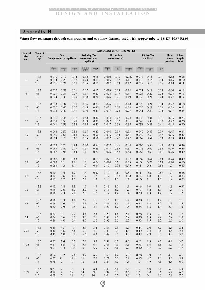
C O P P E R T U B E I N D O M E S T I C W A T E R S E R V I C E S
D E S I G N A N D I N S T A L L A T I O N
17
15.5 0.010 0.16 0.14 0.18 0.11 0.010 0.10 0.082 0.013 0.11 0.11 0.12 0.086 65 0.014 0.20 0.17 0.23 0.14 0.015 0.12 0.11 0.017 0.14 0.14 0.16 0.10
115 0.016 0.21 0.19 0.25 0.15 0.017 0.13 0.12 0.019 0.16 0.16 0.18 0.11
15.5 0.017 0.25 0.21 0.27 0.17 0.019 0.15 0.13 0.021 0.18 0.18 0.20 0.138 65 0.021 0.31 0.27 0.35 0.22 0.024 0.19 0.17 0.026 0.22 0.22 0.24 0.16
115 0.024 0.33 0.29 0.38 0.24 0.026 0.20 0.19 0.030 0.24 0.24 0.27 0.17
15.5 0.023 0.34 0.29 0.36 0.23 0.026 0.21 0.18 0.029 0.24 0.24 0.27 0.1810 65 0.030 0.42 0.37 0.45 0.30 0.032 0.26 0.24 0.036 0.29 0.29 0.33 0.21
115 0.032 0.46 0.41 0.50 0.33 0.037 0.28 0.27 0.041 0.33 0.33 0.37 0.24
15.5 0.030 0.44 0.37 0.48 0.30 0.034 0.27 0.24 0.037 0.31 0.31 0.35 0.2312 65 0.039 0.55 0.49 0.59 0.39 0.042 0.32 0.31 0.046 0.38 0.38 0.42 0.28
115 0.041 0.59 0.52 0.65 0.42 0.047 0.36 0.35 0.053 0.41 0.41 0.48 0.30
15.5 0.043 0.59 0.53 0.65 0.43 0.046 0.39 0.33 0.049 0.43 0.39 0.45 0.3115 65 0.050 0.68 0.62 0.75 0.50 0.056 0.43 0.41 0.059 0.50 0.47 0.56 0.37
115 0.054 0.78 0.68 0.85 0.56 0.062 0.47 0.47 0.067 0.54 0.53 0.63 0.40
15.5 0.052 0.74 0.64 0.80 0.54 0.057 0.46 0.44 0.064 0.52 0.49 0.59 0.3918 65 0.063 0.89 0.77 0.97 0.65 0.073 0.55 0.53 0.078 0.60 0.58 0.70 0.46
115 0.067 0.95 0.84 1.1 0.70 0.076 0.58 0.58 0.084 0.63 0.61 0.76 0.49
15.5 0.068 1.0 0.83 1.0 0.69 0.071 0.59 0.57 0.082 0.64 0.63 0.74 0.4922 65 0.085 1.1 1.0 1.2 0.84 0.090 0.71 0.69 0.10 0.76 0.75 0.90 0.60
115 0.089 1.3 1.1 1.5 0.94 0.10 0.78 0.79 0.11 0.84 0.83 1.0 0.65
15.5 0.10 1.4 1.2 1.5 0.97 0.10 0.81 0.81 0.11 0.87 0.87 1.0 0.6828 65 0.12 1.6 1.4 1.7 1.2 0.12 0.98 0.98 0.14 1.0 1.0 1.2 0.83
115 0.13 1.7 1.5 2.1 1.3 0.13 1.1 1.1 0.16 1.1 1.1 1.4 0.89
15.5 0.13 1.8 1.5 1.9 1.3 0.13 1.0 1.1 0.16 1.0 1.1 1.3 0.9135 65 0.15 2.0 1.7 2.2 1.5 0.15 1.2 1.2 0.17 1.2 1.3 1.5 1.0
115 0.16 2.3 2.0 2.5 1.7 0.17 1.4 1.4 0.20 1.3 1.4 1.7 1.2
15.5 0.16 2.3 1.9 2.4 1.6 0.16 1.2 1.4 0.20 1.1 1.4 1.5 1.142 65 0.18 2.6 2.2 2.8 1.9 0.21 1.4 1.6 0.22 1.3 1.7 1.8 1.4
115 0.20 2.9 2.5 3.2 2.1 0.22 1.7 1.8 0.25 1.5 1.9 2.0 1.5
15.5 0.22 3.1 2.7 3.4 2.3 0.26 1.8 2.1 0.28 1.3 2.1 2.1 1.754 65 0.24 3.6 3.2 3.9 2.6 0.30 2.0 2.4 0.30 1.5 2.4 2.4 1.9
115 0.26 4.0 3.4 4.3 2.8 0.32 2.2 2.5 0.33 1.5 2.5 2.6 2.0
15.5 0.35 4.7 4.1 5.1 3.4 0.35 2.5 3.0 0.44 2.0 3.0 2.9 2.476.1 65 0.40 5.6 4.8 6.0 4.0 0.40 2.9 3.6 0.49 2.4 3.6 3.4 2.8
115 0.49 6.0 5.2 6.6 4.3 0.42 3.1 3.9 0.49 2.9 3.9 3.8 3.0
15.5 0.52 7.4 6.5 7.9 5.3 0.52 3.7 4.8 0.61 2.9 4.8 4.2 3.7108 65 0.61 8.5 7.3 9.1 6.1 0.61 4.3 5.5 0.73 3.6 5.5 4.9 4.3
115 0.61 9.4 7.9 10 6.5 0.67 4.6 6.0 0.80 3.7 6.0 5.2 4.7
15.5 0.64 9.2 7.8 9.7 6.5 0.65 4.4 5.8 0.78 3.9 5.8 4.9 4.6133 65 0.77 11 9.4 12 7.8 0.77 5.3 7.1 0.95 4.7 7.1 5.8 5.5
115 0.78 12 10 13 8.4 0.84 5.7 7.6 1.0 4.9 7.6 6.3 6.0
15.5 0.83 12 10 13 8.4 0.80 5.6 7.6 1.0 5.0 7.6 5.9 5.9159 65 0.97 14 12 14 9.6 0.97 6.3 8.6 1.2 5.8 8.6 6.7 6.7
115 0.98 15 12 16 10 1.0 6.7 9.3 1.2 6.1 9.2 7.2 7.2
Nominalsize
(mm)
Temp ofwater(˚C)
EQUIVALENT LENGTHS IN METRES
Tee(compression or capillary)
Reducing Tee(compression or
capillary)
Pitcher Tee(compression)
Pitcher Tee(capillary)
Elbow(com-
pression)
Elbow(capil-lary)
A p p e n d i x H
Water flow resistance through compression and capillary fittings, used with copper tube to BS EN 1057 R250

C O P P E R T U B E I N D O M E S T I C W A T E R S E R V I C E S
D E S I G N A N D I N S T A L L A T I O N
18
0.063 0.068 0.10 0.092 0.061 0.075 0.17 0.075 0.035 0.034 0.54 0.051 1.0 15.50.078 0.085 0.12 0.12 0.078 0.096 0.21 0.096 0.046 0.043 0.68 0.066 1.3 65 60.083 0.091 0.14 0.13 0.085 0.11 0.23 0.11 0.049 0.047 0.72 0.074 1.4 115
0.10 0.12 0.15 0.15 0.095 0.12 0.27 0.12 0.054 0.052 0.84 0.084 1.6 15.50.12 0.13 0.19 0.18 0.12 0.15 0.33 0.15 0.069 0.064 1.0 0.11 2.1 65 80.13 0.14 0.21 0.20 0.13 0.16 0.36 0.16 0.072 0.069 1.1 0.12 2.2 115
0.13 0.14 0.20 0.20 0.13 0.16 0.37 0.16 0.072 0.069 1.1 0.12 2.2 15.50.16 0.18 0.25 0.25 0.16 0.20 0.45 0.20 0.091 0.083 1.4 0.15 2.7 65 100.18 0.20 0.28 0.28 0.17 0.22 0.50 0.22 0.096 0.091 1.5 0.17 2.9 115
0.17 0.19 0.26 0.25 0.16 0.21 0.47 0.21 0.092 0.085 1.5 0.16 2.8 15.50.21 0.23 0.33 0.31 0.20 0.25 0.57 0.25 0.11 0.10 1.8 0.20 3.6 65 120.22 0.25 0.36 0.35 0.22 0.28 0.65 0.28 0.12 0.11 1.9 0.22 3.8 115
0.24 0.27 0.37 0.33 0.23 0.28 0.65 0.28 0.11 0.12 2.0 0.22 3.7 15.50.28 0.31 0.44 0.41 0.26 0.35 0.75 0.35 0.12 0.14 2.3 0.26 4.6 65 150.30 0.33 0.47 0.45 0.29 0.37 0.85 0.37 0.13 0.15 2.6 0.28 5.0 115
0.28 0.31 0.44 0.41 0.26 0.33 0.80 0.33 0.16 0.15 2.5 0.28 4.8 15.50.35 0.39 0.53 0.48 0.32 0.40 0.96 0.40 0.19 0.18 3.0 0.34 5.8 65 180.36 0.40 0.57 0.52 0.34 0.42 1.1 0.42 0.19 0.18 3.2 0.36 6.1 115
0.37 0.40 0.57 0.51 0.34 0.42 1.0 0.42 0.21 0.20 3.2 0.37 6.1 15.50.46 0.50 0.68 0.61 0.41 0.50 1.2 0.50 0.24 0.23 3.9 0.44 7.4 65 220.49 0.54 0.76 0.67 0.46 0.55 1.4 0.55 0.26 0.24 4.2 0.49 8.1 115
0.52 0.58 0.81 0.68 0.48 0.58 1.5 0.58 0.29 0.27 4.5 0.52 8.6 15.50.64 0.70 0.95 0.83 0.58 0.67 1.7 0.67 0.34 0.31 5.5 0.61 10 65 280.68 0.75 1.0 0.90 0.63 0.73 1.9 0.73 0.35 0.31 5.7 0.68 11 115
0.69 0.76 1.0 0.85 0.60 0.69 1.9 0.69 0.38 0.35 6.0 0.69 11 15.50.80 0.86 1.2 1.0 0.71 0.80 2.2 0.80 0.45 0.42 6.8 0.77 13 65 350.87 0.96 1.3 1.1 0.80 0.85 2.5 0.85 0.48 0.44 7.6 0.87 14 115
0.88 0.95 1.3 1.0 0.75 0.85 2.4 0.85 0.49 0.46 7.5 0.91 14 15.51.0 1.1 1.5 1.2 0.89 1.0 2.8 1.0 0.55 0.52 8.9 1.0 16 65 421.1 1.2 1.6 1.3 1.0 1.1 3.2 1.0 0.58 0.55 9.6 1.2 18 115
1.3 1.4 1.8 1.4 1.1 1.1 3.4 1.3 0.77 0.64 11 1.3 20 15.51.5 1.6 2.1 1.6 1.2 1.3 3.9 1.4 0.87 0.72 12 1.5 22 65 541.5 1.7 2.2 1.7 1.3 1.3 4.3 1.4 0.87 0.71 13 1.6 25 115
1.8 1.8 2.6 1.7 1.5 1.5 4.9 1.6 1.0 0.93 16 1.9 29 15.52.2 2.4 3.1 2.4 1.8 1.8 6.0 1.9 1.2 1.0 19 2.4 34 65 76.12.3 2.5 3.2 2.5 1.9 1.9 6.6 2.0 1.2 1.2 20 2.5 37 115
2.9 3.2 4.1 3.2 2.2 2.1 7.9 2.2 1.6 1.5 25 3.0 45 15.53.3 3.7 4.6 3.7 2.5 2.4 9.2 2.6 1.8 1.7 29 3.5 52 65 1083.5 3.8 4.9 3.8 2.7 2.5 10 2.7 1.9 1.8 31 3.7 56 115
3.6 3.9 4.9 3.9 2.6 2.6 9.7 2.6 1.9 1.8 30 3.7 55 15.54.3 4.7 5.8 4.7 3.2 3.1 11 3.1 2.3 2.2 37 4.5 67 65 1334.5 4.9 6.3 4.8 3.4 3.1 13 3.0 2.4 2.3 40 4.8 72 115
4.6 5.0 6.2 5.1 3.4 3.4 13 3.4 2.5 2.4 40 4.8 71 15.55.3 5.8 7.1 5.8 3.8 3.8 14 3.8 2.9 2.7 45 5.5 82 65 1595.5 6.1 7.5 5.9 4.0 3.8 16 3.8 3.0 2.8 49 5.9 89 115
Nominalsize
(mm)
Temp ofwater(˚C)
EQUIVALENT LENGTHS IN METRES
Twin elbow(compression)
Twin elbow(capillary)
Bend(compr-ession orcapillary)
Return bend
(compression) (capil-lary)
Reducer(compression or
capillary)
Anglevalve
Gatevalve
Stop-cock
(formerly BS 2871: Part 1: Table X)

C O P P E R T U B E I N D O M E S T I C W A T E R S E R V I C E S
D E S I G N A N D I N S T A L L A T I O N
19
15.5 0.009 0.15 0.13 0.17 0.10 0.009 0.09 0.08 0.012 0.10 0.10 0.11 0.0786 65 0.013 0.18 0.16 0.21 0.13 0.014 0.11 0.10 0.016 0.13 0.13 0.15 0.094
115 0.014 0.19 0.17 0.23 0.14 0.015 0.12 0.11 0.017 0.14 0.14 0.16 0.10
15.5 0.016 0.24 0.20 0.26 0.16 0.018 0.15 0.12 0.020 0.17 0.17 0.19 0.128 65 0.020 0.29 0.25 0.33 0.21 0.022 0.17 0.16 0.025 0.20 0.20 0.23 0.15
115 0.022 0.31 0.28 0.36 0.22 0.025 0.19 0.18 0.028 0.22 0.22 0.25 0.16
15.5 0.022 0.33 0.28 0.35 0.22 0.025 0.20 0.18 0.027 0.23 0.23 0.26 0.1710 65 0.029 0.40 0.35 0.43 0.29 0.031 0.25 0.23 0.034 0.28 0.28 0.31 0.20
115 0.030 0.43 0.38 0.47 0.31 0.034 0.26 0.26 0.039 0.31 0.31 0.35 0.22
15.5 0.029 0.43 0.36 0.46 0.29 0.033 0.26 0.23 0.036 0.30 0.30 0.33 0.2212 65 0.038 0.53 0.47 0.56 0.38 0.040 0.31 0.30 0.044 0.36 0.36 0.40 0.26
115 0.040 0.57 0.51 0.63 0.41 0.046 0.35 0.34 0.052 0.40 0.40 0.46 0.29
15.5 0.041 0.57 0.51 0.62 0.41 0.044 0.38 0.32 0.047 0.41 0.38 0.43 0.3015 65 0.048 0.65 0.59 0.71 0.48 0.053 0.41 0.38 0.056 0.47 0.44 0.53 0.35
115 0.052 0.74 0.65 0.81 0.53 0.059 0.45 0.44 0.064 0.52 0.50 0.60 0.38
15.5 0.051 0.73 0.63 0.79 0.53 0.056 0.46 0.43 0.063 0.51 0.48 0.58 0.3818 65 0.062 0.88 0.75 0.95 0.64 0.073 0.54 0.52 0.076 0.59 0.57 0.69 0.45
115 0.066 0.93 0.82 1.0 0.68 0.075 0.57 0.57 0.082 0.62 0.60 0.75 0.48
15.5 0.067 0.97 0.82 1.0 0.68 0.070 0.58 0.56 0.080 0.63 0.62 0.73 0.4822 65 0.083 1.1 0.96 1.2 0.82 0.088 0.69 0.68 0.10 0.74 0.73 0.88 0.58
115 0.086 1.2 1.1 1.4 0.91 0.095 0.76 0.77 0.11 0.82 0.80 0.98 0.63
15.5 0.095 1.3 1.0 1.4 0.95 0.095 0.79 0.79 0.10 0.85 0.85 0.98 0.6628 65 0.12 1.6 1.3 1.6 1.1 0.12 0.95 0.95 0.13 1.0 1.0 1.2 0.80
115 0.12 1.7 1.5 2.0 1.3 0.13 1.0 1.1 0.15 1.1 1.1 1.3 0.87
15.5 0.13 1.8 1.5 1.9 1.3 0.13 1.0 1.1 0.16 1.0 1.1 1.3 0.9135 65 0.15 2.0 1.7 2.2 1.5 0.15 1.2 1.2 0.17 1.2 1.3 1.5 1.0
115 0.16 2.3 2.0 2.5 1.7 0.17 1.4 1.4 0.20 1.3 1.4 1.7 1.2
15.5 0.16 2.2 1.9 2.4 1.6 0.16 1.2 1.4 0.19 1.1 1.4 1.5 1.142 65 0.18 2.5 2.2 2.7 1.8 0.21 1.4 1.6 0.22 1.3 1.7 1.7 1.4
115 0.20 2.9 2.5 3.2 2.0 0.22 1.7 1.8 0.24 1.4 1.8 2.0 1.5
15.5 0.22 3.1 2.7 3.4 2.2 0.25 1.7 2.0 0.27 1.3 2.0 2.1 1.654 65 0.24 3.6 3.2 3.9 2.6 0.30 2.0 2.4 0.30 1.5 2.4 2.4 1.9
115 0.26 4.0 3.4 4.3 2.8 0.32 2.2 2.5 0.33 1.5 2.5 2.6 2.0
15.5 0.35 4.7 4.1 5.1 3.4 0.35 2.5 3.0 0.44 2.0 3.0 2.9 2.476.1 65 0.40 5.6 4.8 6.0 4.0 0.40 2.9 3.6 0.49 2.4 3.6 3.4 2.8
115 0.49 6.0 5.2 6.6 4.3 0.42 3.1 3.9 0.49 2.9 3.9 3.8 3.0
15.5 0.52 7.4 6.5 7.9 5.3 0.52 3.7 4.8 0.61 2.9 4.8 4.2 3.7108 65 0.61 8.5 7.3 9.1 6.1 0.61 4.3 5.5 0.73 3.6 5.5 4.9 4.3
115 0.61 9.4 7.9 10 6.5 0.67 4.6 6.0 0.80 3.7 6.0 5.2 4.7
Nominalsize
(mm)
Temp ofwater(˚C)
EQUIVALENT LENGTHS IN METRES
Tee(compression or capillary)
Reducing Tee(compression or
capillary)
Pitcher Tee(compression)
Pitcher Tee(capillary)
Elbow(com-
pression)
Elbow(capil-lary)
Water flow resistance through compression and capillary fittings, used with copper tube to BS EN 1057 R220 and

C O P P E R T U B E I N D O M E S T I C W A T E R S E R V I C E S
D E S I G N A N D I N S T A L L A T I O N
20
0.059 0.064 0.089 0.086 0.057 0.070 0.16 0.070 0.033 0.032 0.50 0.048 0.96 15.50.071 0.078 0.11 0.11 0.071 0.088 0.19 0.088 0.042 0.039 0.62 0.060 1.2 65 60.075 0.082 0.12 0.12 0.077 0.097 0.21 0.097 0.044 0.042 0.65 0.066 1.3 115
0.092 0.10 0.14 0.14 0.090 0.11 0.26 0.11 0.051 0.049 0.79 0.079 1.5 15.50.11 0.12 0.18 0.17 0.11 0.14 0.31 0.14 0.064 0.060 0.96 0.10 2.0 65 80.12 0.13 0.20 0.19 0.12 0.16 0.34 0.16 0.068 0.065 1.0 0.11 2.0 115
0.13 0.14 0.20 0.19 0.12 0.15 0.36 0.15 0.069 0.066 1.1 0.10 2.1 15.50.15 0.17 0.24 0.23 0.15 0.19 0.43 0.19 0.087 0.079 1.3 0.14 2.6 65 100.17 0.19 0.27 0.26 0.16 0.21 0.48 0.21 0.091 0.086 1.4 0.16 2.8 115
0.16 0.18 0.25 0.25 0.16 0.20 0.46 0.20 0.089 0.082 1.4 0.16 2.7 15.50.20 0.22 0.31 0.30 0.19 0.24 0.54 0.24 0.11 0.10 1.7 0.19 3.4 65 120.22 0.24 0.35 0.34 0.21 0.28 0.63 0.28 0.12 0.11 1.9 0.22 3.7 115
0.23 0.25 0.35 0.32 0.22 0.27 0.62 0.27 0.10 0.11 1.9 0.21 3.6 15.50.26 0.30 0.41 0.38 0.24 0.33 0.71 0.32 0.12 0.13 2.2 0.24 4.4 65 150.28 0.32 0.45 0.43 0.27 0.36 0.81 0.36 0.13 0.14 2.4 0.27 4.7 115
0.28 0.30 0.43 0.41 0.25 0.33 0.79 0.33 0.16 0.15 2.5 0.28 4.7 15.50.34 0.38 0.52 0.47 0.31 0.39 0.95 0.39 0.19 0.18 3.0 0.33 5.6 65 180.36 0.39 0.56 0.51 0.34 0.41 1.0 0.41 0.19 0.18 3.1 0.36 6.0 115
0.36 0.39 0.56 0.50 0.34 0.42 1.0 0.42 0.20 0.19 3.2 0.36 6.1 15.50.45 0.49 0.67 0.59 0.40 0.49 1.2 0.49 0.24 0.22 3.8 0.43 7.2 65 220.48 0.53 0.74 0.66 0.45 0.53 1.4 0.53 0.25 0.23 4.1 0.48 7.9 115
0.50 0.57 0.79 0.66 0.47 0.57 1.4 0.57 0.28 0.27 4.4 0.50 8.4 15.50.62 0.68 0.92 0.80 0.56 0.65 1.7 0.65 0.33 0.30 5.3 0.59 10 65 280.66 0.73 1.0 0.88 0.61 0.71 1.9 0.71 0.34 0.31 5.6 0.66 11 115
0.69 0.76 1.0 0.85 0.60 0.69 1.9 0.69 0.38 0.35 6.0 0.69 11 15.50.80 0.86 1.2 1.0 0.71 0.80 2.2 0.80 0.45 0.42 6.8 0.77 13 65 350.87 0.96 1.3 1.1 0.80 0.85 2.5 0.85 0.48 0.44 7.6 0.87 14 115
0.87 0.94 1.3 1.0 0.74 0.84 2.4 0.84 0.48 0.45 7.4 0.90 14 15.51.0 1.1 1.5 1.2 0.87 0.96 2.7 0.96 0.54 0.51 8.7 1.0 16 65 421.1 1.2 1.6 1.3 0.97 1.1 3.2 1.0 0.57 0.54 9.5 1.2 18 115
1.2 1.4 1.8 1.4 1.0 1.1 3.4 1.2 0.75 0.63 11 1.3 19 15.51.5 1.6 2.1 1.6 1.2 1.3 3.9 1.4 0.87 0.72 12 1.5 22 65 541.5 1.7 2.2 1.7 1.3 1.3 4.3 1.4 0.87 0.71 13 1.6 25 115
1.8 1.8 2.6 1.7 1.5 1.5 4.9 1.6 1.0 0.93 16 1.9 29 15.52.2 2.4 3.1 2.4 1.8 1.8 6.0 1.9 1.2 1.0 19 2.4 34 65 76.12.3 2.5 3.2 2.5 1.9 1.9 6.6 2.0 1.2 1.2 20 2.5 37 115
2.9 3.2 4.1 3.2 2.2 2.1 7.9 2.2 1.6 1.5 25 3.0 45 15.53.3 3.7 4.6 3.7 2.5 2.4 9.2 2.6 1.8 1.7 29 3.5 52 65 1083.5 3.8 4.9 3.8 2.7 2.5 10 2.7 1.9 1.8 31 3.7 56 115
Nominalsize
(mm)
Temp ofwater(˚C)
EQUIVALENT LENGTHS IN METRES
Twin elbow(compression)
Twin elbow(capillary)
Bend(compr-ession orcapillary)
Return bend
(compression) (capil-lary)
Reducer(compression or
capillary)
Anglevalve
Gatevalve
Stop-cock
R250 (formerly BS 2871: Part 1: Table Y).

C O P P E R T U B E I N D O M E S T I C W A T E R S E R V I C E S
D E S I G N A N D I N S T A L L A T I O N
21
Water flow resistance through copper tube to BS EN 1057 R250 (Formerly Table X) .
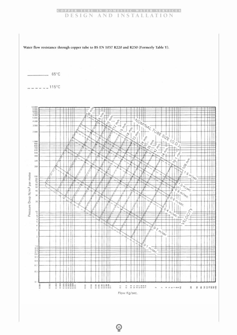
C O P P E R T U B E I N D O M E S T I C W A T E R S E R V I C E S
D E S I G N A N D I N S T A L L A T I O N
22
Water flow resistance through copper tube to BS EN 1057 R220 and R250 (Formerly Table Y).

C O P P E R T U B E I N D O M E S T I C W A T E R S E R V I C E S
D E S I G N A N D I N S T A L L A T I O N
23
The Building Regulations 1985Materials and workmanshipAny work to which a requirement of the BuildingRegulations applies must, in accordance withRegulation 7, be carried out with proper materials andin a workmanlike manner.
Compliance may be shown in a number of ways, forexample by following the relevant British Standard orBritish Board of Agrément Certificate. Further guidanceis given in the Approved Document on Materials andWorkmanship.
Hot water storagePart G3 of the Building Regulations requires that if thehot water storage system does not incorporate a ventpipe to atmosphere adequate precautions should betaken to prevent the temperature of the stored water atany time exceeding 100o C. The maximum workingpressures quoted in this publication for copper tube arebased on maximum operating temperatures notexceeding 110o C.
Insulation of heating servicesPart L5 of the Building Regulations requires that hotwater pipes should have adequate thermal insulationunless they are intended to contribute to the heating ofpart of a building that is insulated. The provisionsmeeting the requirements regarding maximum thermalconductivity and rates of heat loss are also tabled in L5.
A range of insulating materials are available for coppertubes including factory fitted plastic sleeving and post
installation insulation. Reference should be made to themanufacturers’ literature for details of the thermalperformance of insulated copper pipework. It should benoted that some plastic coated copper tube is producedprimarily for corrosion protection in aggressiveenvironments such as acid soils. In these circumstancesthe insulating properties may not be adequate for hotwater applications.
British Standards Specification BS 6700‘Design, installation, testing and maintenance ofservices supplying water for domestic use withinbuildings and their curtilages’.
This Specification brings together in one publicationvirtually all aspects of hot and cold water supply withina building and its immediate surroundings. It does notcover water treatment, fire fighting systems and watersupply for industrial treatments.
The term ‘domestic water service’ is defined as thesystem of pipes, fittings and connected appliancesinstalled to supply a building with water for ablutionary,cleaning, sanitary, culinary and laundry purposes. Thespecification deals with the plumbing aspects of boththe hot water conveyed for use and hot water conveyedfor space heating. However it does not cover domesticcentral heating installation appliances.
The scope of this publication ‘Copper Tube in DomesticWater Services’ is similar to that of the British StandardSpecification whilst concentrating on aspects of coppertube usage.
A p p e n d i x I
Regulations and Statutory Requirements
R e f e r e n c e s
British and European Standard Specifications
BS EN 1057 Copper and copper alloys – Seamlessround copper tubes for water and gasin sanitary and heating applications.
BS EN 1254 Copper and copper alloys – PlumbingfittingsPart 1 Fittings with ends for capillarysoldering or capillary brazing tocopper tubes.Part 2 Fittings with compression endsfor use with copper tubes.Part 5 Fittings with short ends forcapillary brazing to copper tubes.
BS 1306 Specification for copper and copperalloy pressure piping systems
BS 1566 Copper indirect cylinders fordomestic purposes.Part 1 Specification for double feedindirect cylinders.Part 2 Specification for single feedindirect cylinders.
BS 1710 Specification for identification ofpipelines and services
BS 1723 Brazing
BS 1724 Specification for bronze welding bygas
BS 1845 Specification for filler metals forbrazing.

C O P P E R T U B E I N D O M E S T I C W A T E R S E R V I C E S
D E S I G N A N D I N S T A L L A T I O N
24
BS 3958 Specification for thermal insulatingmaterials
BS 4504 Specification for flanges and boltingfor pipes, valves and fittings: MetricseriesPart 3: Section 3.3 Copper alloy andcomposite flanges
BS 4800 Schedule of paint colours for buildingpurposes
BS 5422 Method for specifying thermalinsulating materials on pipes,ductwork and equipment(Temperature range –40oC - +700oC)
BS 5431 Specification for bending springs foruse with copper tubes for water, gasand sanitation
BS 6700 Specification for Design, installation,testing and maintenance of servicessupplying water for domestic usewithin buildings and their curtilages.
BS EN 12164 Rod for free machining purposes.
BS EN 12165 Wrought and unwrought forging stock
BS EN 12167 Profiles and rectangular bar forgeneral purposes.
BS EN 29453 Soft solder alloys – Chemicalcompositions and forms.
BS EN ISO 9000 Quality management and qualityassurance standards.
British Standards Institution, 389 Chiswick High Road,London. W4 4AJ
Other referencesS F White, G D Mays ‘Water Supply Byelaws Guide’Water Research Centre,Water Byelaws Advisory Service, 660 Ajax Avenue,Slough, Berks, SL1 4BG
The Building Regulations 1985Approved DocumentsG HygieneL Conservation of Fuel and PowerDepartment of the Environment and The Welsh OfficeHer Majesty’s Stationery Office
Guidance Note EH 48 ‘Legionnaires’ Disease’Environmental Hygiene Series 48 (January 1987)Health and Safety ExecutiveHer Majesty’s Stationery Office
The Water Fittings and Materials DirectoryWater Research Centre,Water Byelaws Advisory Service, 660 Ajax Avenue,Slough, Berks. SLl 4BG
Technical Memorandum TM13 ‘Minimising the Risk ofLegionnaires’ Disease’The Chartered Institution of Building Services Engineers,Delta House, 222 Balham High Road, London, SW129B5
‘Copper in Domestic Heating Systems’ PublicationTN39, June 1988‘Dezincification Resistant Brass’ Information Sheet IS 36,November 1982Copper Development Association, Verulam IndustrialEstate, 224 London Road, St Albans, Herts. AL1 1AQ
‘Methods of Sterilisation’ HTM27, Department of Healthand Social Services, Her Majesty’s Stationery Office
Other sources of information
‘Plumbing Engineering Services Design Guide’ TheInstitute of Plumbing64 Station Lane, Hornchurch, Essex

C O P P E R T U B E I N D O M E S T I C W A T E R S E R V I C E S
D E S I G N A N D I N S T A L L A T I O N
25
F i g u r e s
Figure 1 Compression fitting
Figure 3 End feed capillary fitting
Figure 5 Horseshoe and loop expansion joints
Figure 2 Integral solder ring capillary fitting
Figure 4 Large diameter compression fitting
Figure 6 Bellows expansion joints

C O P P E R T U B E I N D O M E S T I C W A T E R S E R V I C E S
D E S I G N A N D I N S T A L L A T I O N
26
Figure 7 Gland type expansion joint
Figure 8 Fixings
Figure 9 Method of fixing long lengths of pipework along a wall (Sliding expansion joint)
Figure 10 Method of fixing long lengths of pipework along a wall (Loop expansion joint)

C O P P E R T U B E I N D O M E S T I C W A T E R S E R V I C E S
D E S I G N A N D I N S T A L L A T I O N
27
Figure 11 Indirect unvented (vented primary) system
Figure 12 Indirect unvented (sealed primary) system
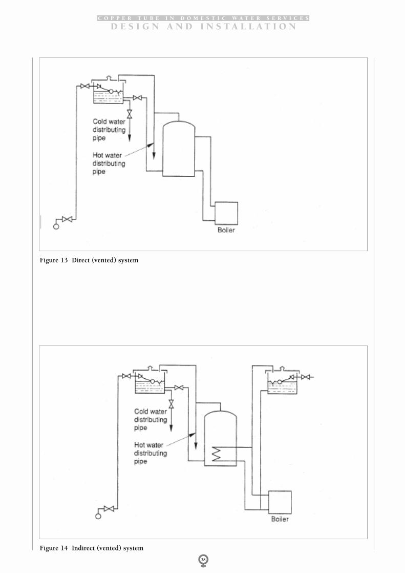
C O P P E R T U B E I N D O M E S T I C W A T E R S E R V I C E S
D E S I G N A N D I N S T A L L A T I O N
28
Figure 13 Direct (vented) system
Figure 14 Indirect (vented) system

N o t e s
31

N o t e s
32

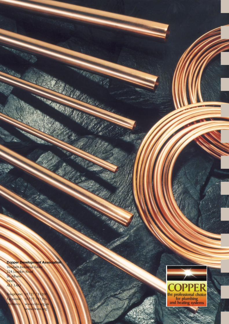
Copper Development AssociationVerulam Industrial Estate224 London RoadSt. AlbansHerts.AL1 1AQ
Telephone: 01727 731200Facsimile: 01727 731216Websites: www.cda.org.uk
www.brass.org