Coplanar Sliding Door System - · PDF fileCoplanar sliding door system for double door wall...
60
Coplanar Sliding Door System
-
Upload
nguyenkhue -
Category
Documents
-
view
216 -
download
0
Transcript of Coplanar Sliding Door System - · PDF fileCoplanar sliding door system for double door wall...

Coplanar Sliding Door System

2
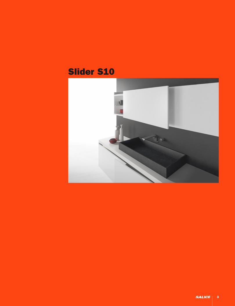
Slider S10
3

Slider S10 - Wall and base cabinet
Coplanar sliding door system for double door wall cabinets with soft opening and soft closing feature.
Product overview
- For wood or glass with aluminum frame doors
Door dimensions:
- Max. weight capacity per door: 10 kg (22 lbs)- Width of the door: min. 450 mm (17-11/16”), max. 1200 mm (47-1/4”) - Max. height of the door: 800 mm (31-1/2”)- Thickness of the door: min. 16 mm (5/8”), max. 30 mm (1-3/16”) - Max. thickness of the door with handle: 40 mm (1-9/16”)- Min. distance of the handle from the edge of the door: 10 mm (3/8”)- Door height adjustment: ± 5.0 mm (±3/16”)- Door side adjustment: ± 2.5 mm (±1/8”)- Door depth: • wall: ± 2.0 (±1/16”) • base: ± 2.5 (±1/8”)
Wall Cabinet
Mechanism attached to the top of the cabinet.
Base Cabinet
Upper guide track attached under the top panel.
Mechanism attached under the bottom panel.
CODE REFERENCES
LI Internal cabinet width (mm) LA Door width (mm)SPI Center panel thickness (mm)SAE Door overlay on side (mm)
KEY FEATURES:
• Innovative sliding door system. • Extremely easy to customise and assemble. • Secured with screws without the need of drilling or machining the doors and change to cabinet.• Single-piece sliding track. • Innovative suspended slider with double horizontal wheels. • Soft opening and soft close feature.• Full adjustment of the doors.
4

x
y
z
Wall Cabinet
44*
230 3
218
63
SPI (MAX 50 mm)
4SAE SAE
17 mm + SAE - (SPI/2)
132
28
15
Minimum space 35 mm for fastening and adjusting.
Top support reinforcement.
Slider S10 - Types of assembly
5

44
70
80
*
230 3
SPI
4
17 mm + SAE - (SPI/2)
SAE SAE
133
6680
218
67
38 mm + SAE
Base Cabinet
Minimum space 35 mm for fastening and adjusting.
Single-piece sliding track.
Two-piece sliding track (Only for custom orders).
Base support reinforcement.
Slider S10 - Types of assembly
x
y
z
6

Slider S10 is a flexible system that can be adapted to the internal width of the cabinet (LI) with a minimum of 860 mm (33 - 7/8”) to a maximum of 2400 mm (94 - 1/2”).
The handle must be positioneted at a minimum 10 mm (3/8”) from the edge of the door and a maximum of one third of its width (LA).
The maximum overlay on the side panel is 25 mm (1”).
LI
17 mm + SAE - (SPI/2)
Min 10 mmMax LA/3
230
70
80
230
LA
SAE
LI
17 mm + SAE - (SPI/2)
Min 10 mmMax LA/3
230
70
80
230
LA
SAE
LI
17 mm + SAE - (SPI/2)
Min 10 mmMax LA/3
230
70
80
230
LA
SAE
Technical specifications
7
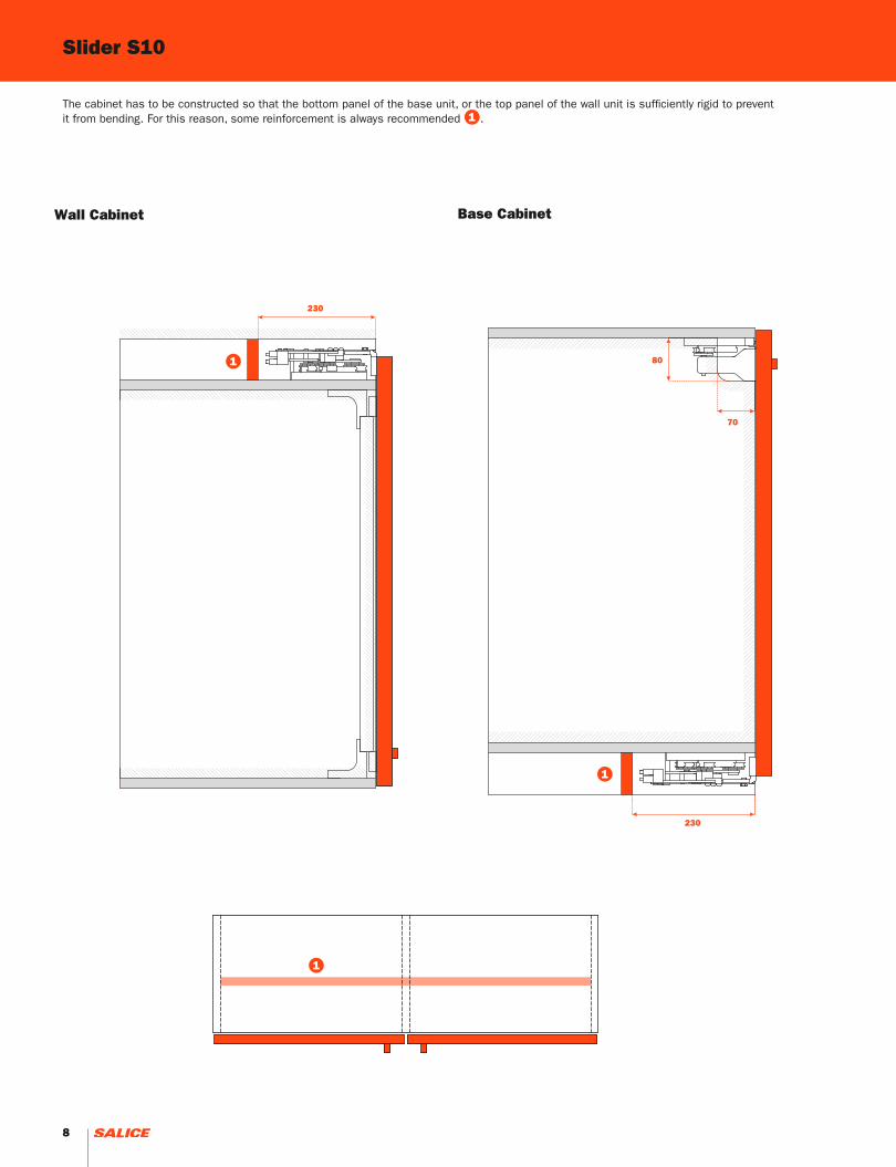
Slider S10
The cabinet has to be constructed so that the bottom panel of the base unit, or the top panel of the wall unit is sufficiently rigid to prevent it from bending. For this reason, some reinforcement is always recommended 1 .
LI
17 mm + SAE - (SPI/2)
Min 10 mmMax LA/3
230
70
80
230
LA
SAE
LI
17 mm + SAE - (SPI/2)
Min 10 mmMax LA/3
230
70
80
230
LA
SAE
1
1
1
Base CabinetWall Cabinet
LI
17 mm + SAE - (SPI/2)
Min 10 mmMax LA/3
230
70
80
230
LA
SAE
8

Slider S10A solution for a whole range of applications that requires the aluminium and PVC profiles to be measured and cut, and the mechanism assembled. Depending on the internal width of the unit (LI), the mechanism is put together using a carriage kit 1 and a profile kit 2 and base cabinet M or wall cabinet P accessories.
Slider S10 - Product codes
LI (mm)
860 ÷ 987 988 ÷ 1115 1116 ÷ 1371 1372 ÷ 1627 1628 ÷ 1883 1884 ÷ 2139 2140 ÷ 2400
YE57KIT0101 -
YE57KIT0102 -
YE57KIT0103 -
YE57KIT0104 -
YE57KIT0105 -
YE57KIT0106 -
YE57KIT0107 -
YE57KIT0201
YE57KIT0202
YE57KIT0301
YE57KIT0302
PM
M 2
1
P 2
LI
PM
M
P
M
M
P
P
M
M
P
P
M
M
P
P
PM
PM
PM
PM
PM
PM
9

10
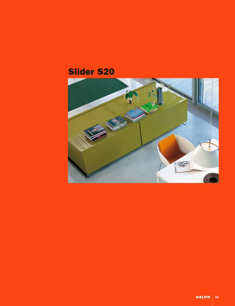
Slider S20
11
x 2
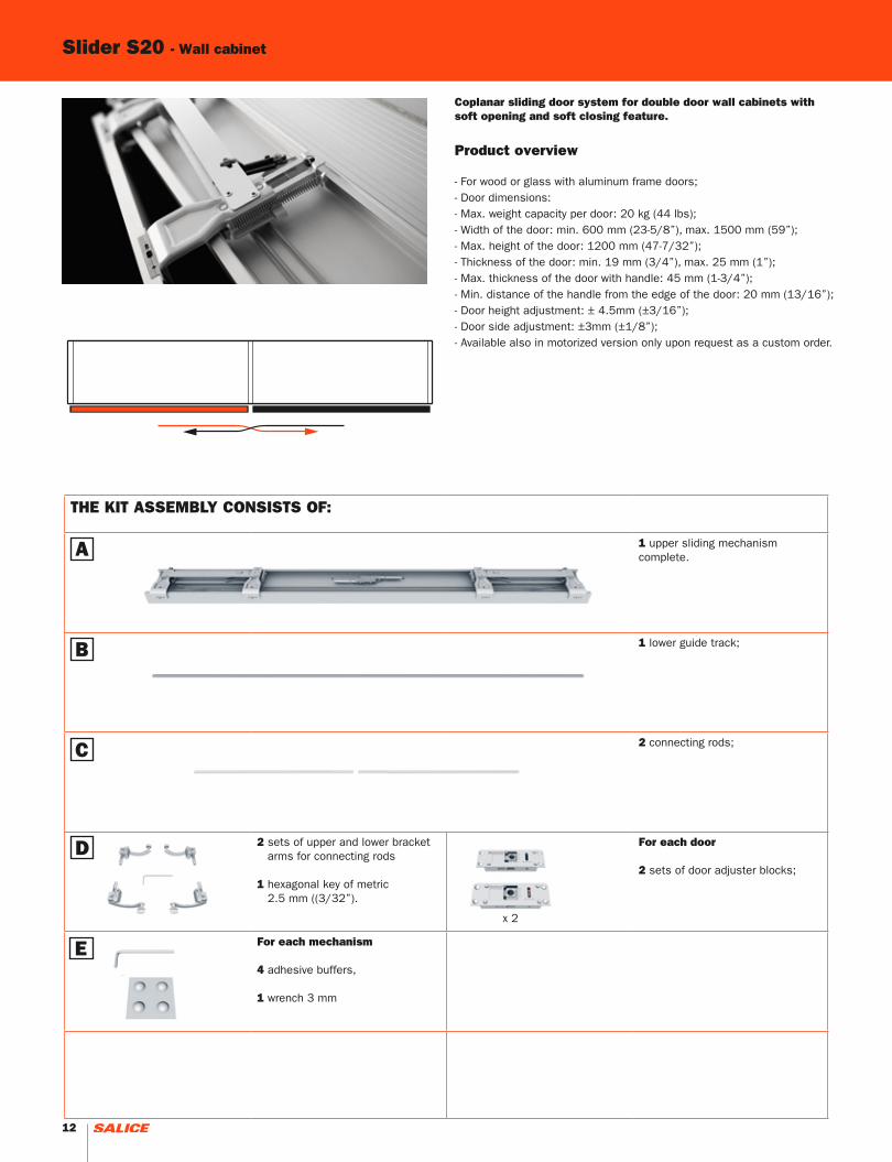
THE KIT ASSEMBLY CONSISTS OF:
1 upper sliding mechanism complete.
1 lower guide track;
2 connecting rods;
2 sets of upper and lower bracket arms for connecting rods 1 hexagonal key of metric 2.5 mm ((3/32”).
For each door
2 sets of door adjuster blocks;
For each mechanism
4 adhesive buffers,
1 wrench 3 mm
Slider S20 - Wall cabinet
Coplanar sliding door system for double door wall cabinets with soft opening and soft closing feature.
Product overview
- For wood or glass with aluminum frame doors;- Door dimensions:- Max. weight capacity per door: 20 kg (44 lbs);- Width of the door: min. 600 mm (23-5/8”), max. 1500 mm (59”);- Max. height of the door: 1200 mm (47-7/32”);- Thickness of the door: min. 19 mm (3/4”), max. 25 mm (1”);- Max. thickness of the door with handle: 45 mm (1-3/4”);- Min. distance of the handle from the edge of the door: 20 mm (13/16”);- Door height adjustment: ± 4.5mm (±3/16”);- Door side adjustment: ±3mm (±1/8”);- Available also in motorized version only upon request as a custom order.
A
B
C
D
E
12

x
y
z
Upper slide mechanism fixed to the top of the cabinet.
A
B
C
D
E
D C
D
D
E
Lower guide track inserted into the bottom panel.
Position the adjusterblocks on the door.
13
SPILI
SAE (max 48 mm - 1-7/8”)
SAE (max 48 mm - 1-7/8”)
min 10 mm (3/8”)
LALA4 (5/32”)
39 + SAE - (SPI/2)
SPC (max 20 mm - 3/4”)
HI
44
*
HA
SAB
3
max 45 mm (1-3/4”)33
max 30 mm (1 - 3/16”)
8
12.4
12
185
76
min 16 mm (5/8”) min 16 mm (5/8”)
min 10 mm (3/8”)
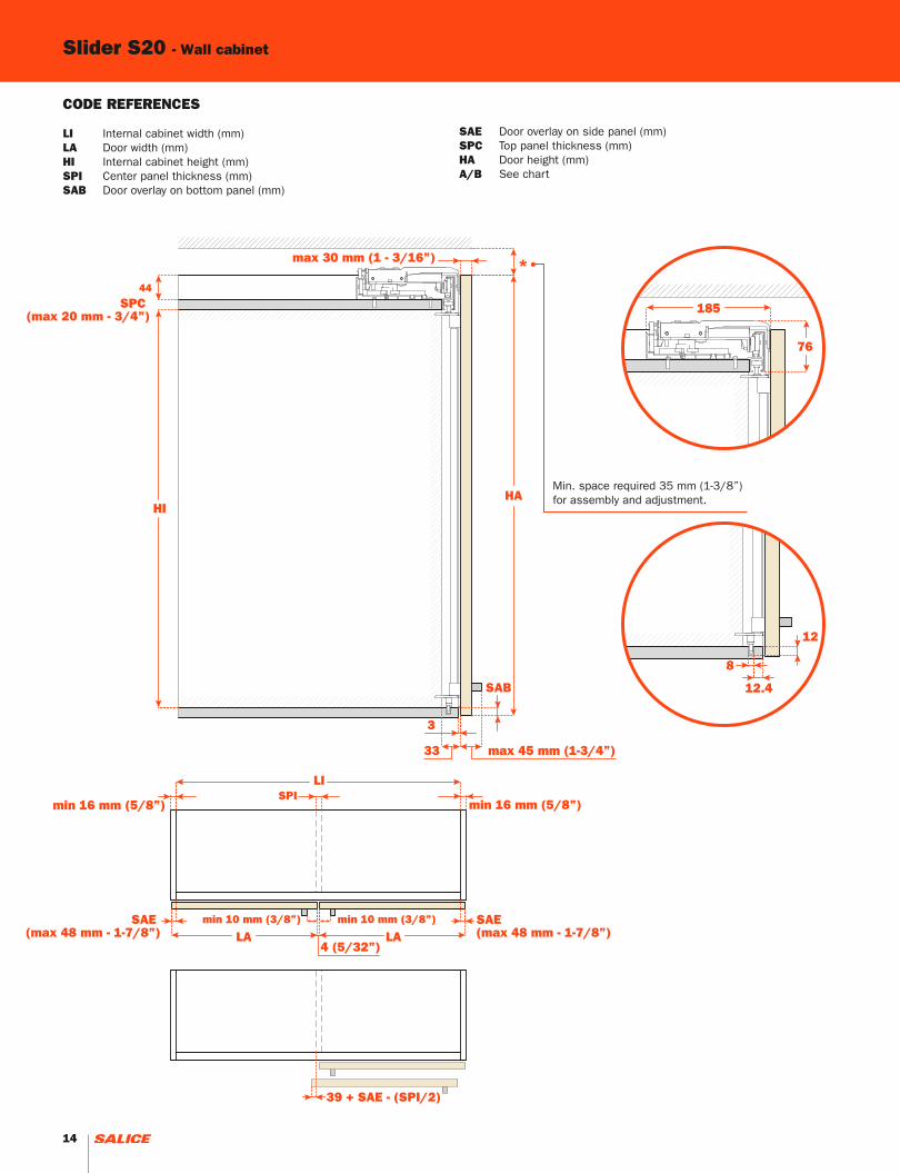
CODE REFERENCES
LI Internal cabinet width (mm)LA Door width (mm)HI Internal cabinet height (mm)SPI Center panel thickness (mm)SAB Door overlay on bottom panel (mm)
SAE Door overlay on side panel (mm)SPC Top panel thickness (mm)HA Door height (mm)A/B See chart
Min. space required 35 mm (1-3/8”) for assembly and adjustment.
Slider S20 - Wall cabinet
14
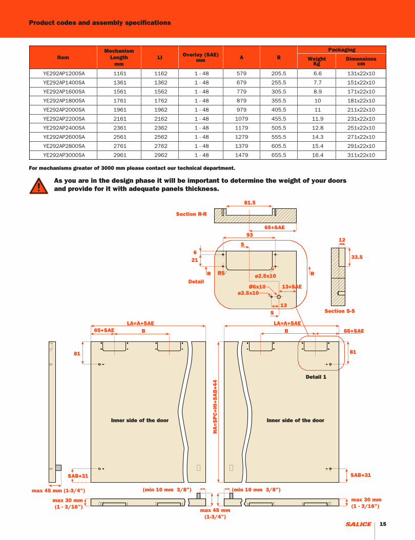
ItemMechanism
Lengthmm
LI Overlay (SAE)mm A B
Packaging
WeightKg
Dimensionscm
YE292AP1200SA 1161 1162 1 - 48 579 205.5 6.6 131x22x10
YE292AP1400SA 1361 1362 1 - 48 679 255.5 7.7 151x22x10
YE292AP1600SA 1561 1562 1 - 48 779 305.5 8.9 171x22x10
YE292AP1800SA 1761 1762 1 - 48 879 355.5 10 181x22x10
YE292AP2000SA 1961 1962 1 - 48 979 405.5 11 211x22x10
YE292AP2200SA 2161 2162 1 - 48 1079 455.5 11.9 231x22x10
YE292AP2400SA 2361 2362 1 - 48 1179 505.5 12.8 251x22x10
YE292AP2600SA 2561 2562 1 - 48 1279 555.5 14.3 271x22x10
YE292AP2800SA 2761 2762 1 - 48 1379 605.5 15.4 291x22x10
YE292AP3000SA 2961 2962 1 - 48 1479 655.5 16.4 311x22x10
Product codes and assembly specifications
81
SAB+31
HA
=S
PC
+H
I+S
AB
+4
4
LA=A+SAE65+SAEB
(min 10 mm 3/8”)(min 10 mm 3/8”)
max 45 mm(1-3/4”)
max 45 mm (1-3/4”)
93
621
ø2.5x10Ø6x10
13
R5R R
S
S
81.5
65+SAE
33.5
12
ø2.5x10
LA=A+SAE65+SAE B
81
SAB+31
max 30 mm(1 - 3/16”)
max 30 mm(1 - 3/16”)
13+SAEDetail
For mechanisms greater of 3000 mm please contact our technical department.
As you are in the design phase it will be important to determine the weight of your doors and provide for it with adequate panels thickness.
Inner side of the door Inner side of the door
Detail 1
Section R-R
Section S-S
15

x 2
x 1x 4 / 6 / 8
THE KIT ASSEMBLY CONSISTS OF:
1 lower sliding mechanism
1 upper guide track
For each mechanism
4 / 6 / 8 fixing clips for upper guide runner
For each door
2 guides for upper runner
For each mechanism
2 couples of door adjuster blocks
For each mechanism
2 upper brackets
For each mechanism
2 cover plates for upper brackets
For each mechanism
4 adhesive buffers
1 wrench 3 mm
Coplanar Sliding Door System for double door base cabinetswith soft opening and soft closing feature.
Product overview
- For wood or glass with aluminium frame dooors;- Door dimensions:- Max. weight capacity per door: 20 kg (44 lbs);- Width of the door: min. 600 mm (23-5/8”), max. 1500 mm 59”);- Max. height of the door: 1200 mm (47-7/32”);- Thickness of the door: min. 19 mm (3/4”), max. 25 mm (1”);- Max. thickness of the door with handle: 45 mm (1-3/4”); - Min. distance of the handle from the edge of the door: 20 mm (13/16”);- Door vertical adjustment: ± 4.5mm (± 3/16”);- Door horizontal adjustment: ±3mm (± 1/8”);- Available also in motorized version only upon request as a custom order.
Slider S20 - Base cabinet
A
B
C D
E F
G
16

x
y
z
Upper guide track fixed under the top panel
Lower sliding mechanism fixedunder the cabinet bottom
Position the adjesterblocks on the doors
A
B C
D
E
F
G
D
E
17

min 16 mm(5/8”)
min 16 mm(5/8”)
SPILI
LA LA4
17 + SAE - (SPI/2)
100
70
HI
44
HA
*
60
185
3
SAC
max 45 mm(1-3/4”)
60
93
125
SAE (max 48 mm)(1-7/8”)
min 10 mm (3/8”)SAE
(max 48 mm)(1-7/8”)
min 10 mm (3/8”)
SPB
max 30 mm(1 - 3/16”)
Slider S20 - Base cabinet
Min. space 35 mm (1-3/8”)required for assembly and adjustment.
CODE REFERENCES
LI Internal cabinet width (mm)LA Door width (mm)HI Internal cabinet height (mm)SPI Central panel thickness (mm)SAE Door overlay on side panel (mm)
SAC Door overlay on top panel (mm)SPB Bottom panel thickness (mm)HA Door height (mm)A/B See chart
18
32
SAC+29
24+SAE25
LA=A+SAE
65+SAEB
max 30 mm(1 - 3/16”)
min 10 mm (3/8”)
93
621
R5
R
R
S S
ø2.5x10
ø2.5x10
33.5
12
81.5
65+SAE
HA
=S
AC
+H
I+S
PB
+4
4
32
SAC+29
24+SAE 25LA=A+SAE
65+SAE B
max 30 mm(1 - 3/16”)
max 45 mm(1-3/4”)
max 45 mm (1-3/4”)
min 10 mm (3/8”)
max 30 mm(1 - 3/16”)
ø2.5x10
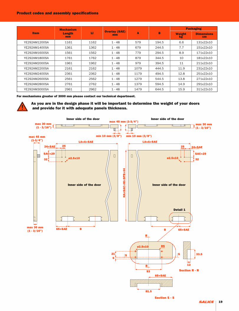
Product codes and assembly specifications
ItemMechanism
Length mm
LI Overlay (SAE)mm A B
Packaging
Weightkg
Dimensions cm
YE292AM1200SA 1161 1162 1 - 48 579 194.5 6.6 131x22x10
YE292AM1400SA 1361 1362 1 - 48 679 244.5 7.7 151x22x10
YE292AM1600SA 1561 1562 1 - 48 779 294.5 8.9 171x22x10
YE292AM1800SA 1761 1762 1 - 48 879 344.5 10 181x22x10
YE292AM2000SA 1961 1962 1 - 48 979 394.5 11 211x22x10
YE292AM2200SA 2161 2162 1 - 48 1079 444.5 11.9 231x22x10
YE292AM2400SA 2361 2362 1 - 48 1179 494.5 12.8 251x22x10
YE292AM2600SA 2561 2562 1 - 48 1279 544.5 13.8 271x22x10
YE292AM2800SA 2761 2762 1 - 48 1379 594.5 14.9 291x22x10
YE292AM3000SA 2961 2962 1 - 48 1479 644.5 15.9 311x22x10
Inner side of the door Inner side of the door
Inner side of the door Inner side of the door
Detail 1
For mechanisms greater of 3000 mm please contact our technical department.
As you are in the design phase it will be important to determine the weight of your doors and provide for it with adequate panels thickness.
Section R - R
Section S - S19

20
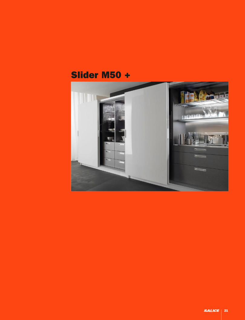
Slider M50 +
21

x 2
Product overview
Coplanar Sliding Door System for tall double door cabinets with soft opening and closing feature.
•For wood or glass with aluminum frame doors;•Maximum weight capacity per door: 50 Kg (110 lbs); Door dimensions:•Soft opening and closing of the doors;•Width of the door: min 600 mm (23-5/8”), max 2000 mm (78-3/4”);•Height of the door from floor level: 17 mm (11/16”);•Door height adjustment: ± 5 mm (3/16”);•Door side adjustment: ±3.5 mm (1/8”);•Compatible with our Clipper-aluminum door system.
Available also in motorized version with max. weight door of
35 Kg (77 Lbs) only upon request as a custom order;
Specifications for mechanisms with overall lengths between 1199 mm (47-7/32”) and 1599 mm (63”)•Max. door height: 2200 mm (86-5/8”);•Adaptability to cabinets up to 100 mm (4”) wider than the track.Specifications for mechanisms with overall lengths between 1600 mm (63”) and 1999 mm (78-3/4”)- Max. door height: 2400 mm (95-1/2”);- Adaptability to cabinets up to 200 mm (7-7/8”) wider than the track.
x 1
x 4x 1
x 4
x 2
x 1
x 1
x 4
x 4
Slider M50 +
Specifications for mechanisms with overall lengths between 2000 mm (78-3/4”) - 2799 mm (110-3/16”) •Max. door height: 3000 mm (118-1/8”);•Adaptability to carcases up to 200 mm (7-7/8”) wider than the track;
THE KIT ASSEMBLY CONSISTS OF
Upper sliding mechanism.
Lower sliding mechanism.
Front covers.
For each sliding mechanism
Note: The quantity of clips will vary according to the track sizes. - Upper track fixing clip; - Lower track fixing clip.
For each door
1 horizontal and vertical adjuster; 1 vertical adjuster; 4 die-cast bushings M6x23; 4 special screws TE M6x22.
For each door
2 spacers for surface mounted adjusters.
For each sliding mechanism
2 bushings M6x13.
For each sliding mechanism
1 hex wrench 4 mm; 1 wrench metric 10 mm; 4 black bumpers; 4 screws TCEI M5x16.
A
B
C D
E
22

x
y
z
Upper sliding mechanism fixed to the top of the cabinet
Lower sliding mechanism fixed under the cabinet bottom
Recessed-mounted adjusters
Door thickness: min 19 mm (3/4”), max. 45 mm (1-3/4”) (including handle protrusion)
Surface mount adjusters
Door thickness: min 19 mm (3/4”), max. 40 mm (1-9/16”) (including handle protrusion)
A
B
C
C
23

min 19 mm(3/4”)
SPI
min 19 mm(3/4”)
DBS + SAE - (SPI/2) +2.5
5LA LA
SAE(max 25 mm)
(1”)DBS (max 100 mm) (4”)*
DBS(max 100 mm) (4”)*
SAE(max 25 mm)(1”)
HA
7
HIHT
60
Min.60
219262
208,5*251*
HAHIHT
60
Min.60
6060
7
18 24 18 24
max 40 mm(1-9/16”)
max 45 mm(1-3/4”)
min. 60 min. 60
LI
LP
SPB
150
43
12.5
55
SPB
150
43
12.5
55
SPC SPC
* With Clipper frame + 6 mm (1/4”)
CODE REFERENCES
LI Internal cabinet width (ID) (mm)LA Door width (mm)HI Internal cabinet height (mm)SPI Support panel thickness (mm)SAE Door overlay on side panel (mm)SPC Top panel thicknessSPB Bottom panel thicknessHA Door height (mm)HT Total cabinet height (mm)DBS Space between track and side panel (mm)LP Track length
* DBS max 50 mm (2”) for mechanisms between 1199 mm (47-7/32”) and 1499 mm (59”)
The M50 + Stock size slider mechanisms can be installed on a carcase which may exceed the dimensions of the track itself by 100/200 mm (4” to 7-7/8”). The protrusion of the door in aopen position is describe with the formula:DBS + SAE - (SPI/2) + 2.5
TrackFront cover
Recessed-mounted adjustersSurface mount adjusters
Slider M50 +
24

Item #
Track length(Lp) mm
LiOverlay
(SAE) mmA B C D
Packaging Clipper frame
Max doorHeight mmKg cm
YE512AM501200SU 1199 1200-1300 1 - 25 344 179 310.4 101.6 17.8 132x25x17 NO 2200
YE512AM501300SU 1299 1300-1400 1 - 25 369 204 335.4 126.6 18.7 142x25x17 NO 2200
YE512AM501400SU 1399 1400-1500 1 - 25 394 204 360.4 151.6 19.6 152x25x17 NO 2200
YE512AM501500SU 1499 1500-1600 1 - 25 419 254 385.4 176.6 20.7 162x25x17 NO 2200
YE512AM501600SU 1599 1600-1800 1 - 25 444 254 410.4 176.6 21.5 172x25x17 YES 2400
YE512AM501800SU 1799 1800-2000 1 - 25 494 304 460.4 226.6 23.3 192x25x17 YES 2400
YE512AM502000SU 1999 2000-2200 1 - 25 544 354 510.4 276.6 25 212x25x17 YES 3000
YE512AM502200SU 2199 2200-2400 1 - 25 594 404 560.4 326.6 26.8 232x25x17 YES 3000
YE512AM502400SU 2399 2400-2600 1 - 25 644 454 610.4 376.6 28.6 252x25x17 YES 3000
YE512AM502600SU 2599 2600-2800 1 - 25 694 504 660.4 426.6 30.5 272x25x17 YES 3000
YE512AM502800SU 2799 2800-3000 1 - 25 744 554 710.4 476.6 32.3 292x25x17 YES 3000
YE512AM503000SU 2999 3000-3200 1 - 25 794 604 760.4 526.6 34.1 312x25x17 YES 3000
YE512AM503200SU 3199 3200-3400 1 - 25 844 654 810.4 576.6 35.9 322x25x17 NO 3000
YE512AM503400SU 3399 3400-3600 1 - 25 894 704 860.4 626.6 37.7 352x25x17 NO 3000
YE512AM503600SU 3599 3600-3800 1 - 25 944 754 910.4 676.6 39.5 372x25x17 NO 3000
YE512AM503800SU 3799 3800-4000 1 - 25 994 804 960.4 726.6 41.3 392x25x17 NO 3000
Product codes and assembly specifications Recessed-mounted adjusters
A
73
2525
25
CC
56 56
Ø4x10 Ø4x10
min 19 mm (3/4”)max 30 mm (1-3/16”)
HA
= H
I +
SP
C +
SP
B +
10
3
DD64
25
64
12,5
114
10
17
R4
Ø8x10
ø2,5x10
11
96
45
6464 64
25
73
9
AB B
LA = (LI/2 + SAE - 2,5) LA = (LI/2 + SAE - 2,5)max
45 mm(1-3/4”)
min 10 mm (3/8”)max 45 mm
(1-3/4”)
Ø4x10 Ø4x10
min 10 mm (3/8”)
As you are in the design phase it will be important to determine the weight of your doors and provide for it with adequate panels thickness.
Close-up 1
Close-up 1
Close-up 1
Ø8x25 sv. 13X90°For bushings m6x23
Door width Door width
Door widthDoor width
Door widthDoor width
Close-up 2 Close-up 2
Close-up 2
25
YE512AM503200SU 3199 3200-3400 1 ÷ 25 844 654 810.4 576.6 35,9 322x25x17 NO 3000
YE512AM503400SU 3399 3400-3600 1 ÷ 25 894 704 860.4 626,6 37,7 352x25x17 NO 3000
YE512AM503600SU 3599 3600-3800 1 ÷ 25 944 754 910.4 676,6 39,5 372x25x17 NO 3000
YE512AM504000SU 3799 3800-4000 1 ÷ 25 994 804 960,4 726,6 41,3 392x25x17 NO 3000
Item #
Track length(Lp) mm
LiOverlay
(sae) mmA B C D
Packaging Clipper frame
Max doorheight mmkg cm
YE512AM501200SU 1199 1200-1300 1 - 25 344 179 310.4 101.6 17.8 132x25x17 NO 2200
YE512AM501300SU 1299 1300-1400 1 - 25 369 204 335.4 126.6 18.7 142x25x17 NO 2200
YE512AM501400SU 1399 1400-1500 1 - 25 394 204 360.4 151.6 19.6 152x25x17 NO 2200
YE512AM501500SU 1499 1500-1600 1 - 25 419 254 385.4 176.6 20.7 162x25x17 NO 2200
YE512AM501600SU 1599 1600-1800 1 - 25 444 254 410.4 176.6 21.5 172x25x17 YES 2400
YE512AM501800SU 1799 1800-2000 1 - 25 494 304 460.4 226.6 23.3 192x25x17 YES 2400
YE512AM502000SU 1999 2000-2200 1 - 25 544 354 510.4 276.6 25 212x25x17 YES 3000
YE512AM502200SU 2199 2200-2400 1 - 25 594 404 560.4 326.6 26.8 232x25x17 YES 3000
YE512AM502400SU 2399 2400-2600 1 - 25 644 454 610.4 376.6 28.6 252x25x17 YES 3000
YE512AM502600SU 2599 2600-2800 1 - 25 694 504 660.4 426.6 30.5 272x25x17 YES 3000
YE512AM502800SU 2799 2800-3000 1 - 25 744 554 710.4 476.6 32.3 292x25x17 YES 3000
YE512AM503000SU 2999 3000-3200 1 - 25 794 604 760.4 526.6 34.1 312x25x17 YES 3000
YE512AM503200SU 3199 3200-3400 1 - 25 844 654 810.4 576.6 35.9 322x25x17 NO 3000
YE512AM503400SU 3399 3400-3600 1 - 25 894 704 860.4 626.6 37.7 352x25x17 NO 3000
YE512AM503600SU 3599 3600-3800 1 - 25 944 754 910.4 676.6 39.5 372x25x17 NO 3000
YE512AM503800SU 3799 3800-4000 1 - 25 994 804 960.4 726.6 41.3 392x25x17 NO 3000
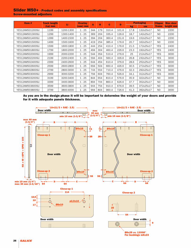
Slider M50+ - Product codes and assembly specificationsScrew-mounted adjusters
LA=(LI/2 + SAE - 2.5) LA=(LI/2 + SAE - 2.5)
A BB A
64min 19 mm (3/4”)max 30 mm (1-3/16”)
HA
= H
I +S
PC
+ S
PB
+ 1
03
D64
C C
5656
ø2,5x10Ø8x10
114
1012,5
9
17
64
25
D64 64
25 25
7373
max 40 mm(1-3/4”)
Ø4x10 Ø4x10
Ø4x10
max40 mm
(1-3/4”)min 10 mm (1-3/8”) min 10 mm (1-3/8”)
Ø4x10
Close-up 1
Close-up 2
As you are in the design phase it will be important to determine the weight of your doors and provide for it with adequate panels thickness.
Close-up 1 Close-up 1
Door width Door width
Door width Door width
Door width Door width
Close-up 2 Close-up 2
Ø8x25 sv. 13X90°For bushings m6x23
26

YE512AM503200SU 3199 3200-3400 1 ÷ 25 844 654 810.4 576.6 35,9 322x25x17 NO 3000
YE512AM503400SU 3399 3400-3600 1 ÷ 25 894 704 860.4 626,6 37,7 352x25x17 NO 3000
YE512AM503600SU 3599 3600-3800 1 ÷ 25 944 754 910.4 676,6 39,5 372x25x17 NO 3000
YE512AM504000SU 3799 3800-4000 1 ÷ 25 994 804 960,4 726,6 41,3 392x25x17 NO 3000
Item #
Track length(Lp) mm
LiOverlay
(sae) mmA B C D
Packaging Clipper frame
Max doorheight mmkg cm
YE512AM501200SU 1199 1200-1300 1 - 25 344 179 310.4 101.6 17.8 132x25x17 NO 2200
YE512AM501300SU 1299 1300-1400 1 - 25 369 204 335.4 126.6 18.7 142x25x17 NO 2200
YE512AM501400SU 1399 1400-1500 1 - 25 394 204 360.4 151.6 19.6 152x25x17 NO 2200
YE512AM501500SU 1499 1500-1600 1 - 25 419 254 385.4 176.6 20.7 162x25x17 NO 2200
YE512AM501600SU 1599 1600-1800 1 - 25 444 254 410.4 176.6 21.5 172x25x17 YES 2400
YE512AM501800SU 1799 1800-2000 1 - 25 494 304 460.4 226.6 23.3 192x25x17 YES 2400
YE512AM502000SU 1999 2000-2200 1 - 25 544 354 510.4 276.6 25 212x25x17 YES 3000
YE512AM502200SU 2199 2200-2400 1 - 25 594 404 560.4 326.6 26.8 232x25x17 YES 3000
YE512AM502400SU 2399 2400-2600 1 - 25 644 454 610.4 376.6 28.6 252x25x17 YES 3000
YE512AM502600SU 2599 2600-2800 1 - 25 694 504 660.4 426.6 30.5 272x25x17 YES 3000
YE512AM502800SU 2799 2800-3000 1 - 25 744 554 710.4 476.6 32.3 292x25x17 YES 3000
YE512AM503000SU 2999 3000-3200 1 - 25 794 604 760.4 526.6 34.1 312x25x17 YES 3000
YE512AM503200SU 3199 3200-3400 1 - 25 844 654 810.4 576.6 35.9 322x25x17 NO 3000
YE512AM503400SU 3399 3400-3600 1 - 25 894 704 860.4 626.6 37.7 352x25x17 NO 3000
YE512AM503600SU 3599 3600-3800 1 - 25 944 754 910.4 676.6 39.5 372x25x17 NO 3000
YE512AM503800SU 3799 3800-4000 1 - 25 994 804 960.4 726.6 41.3 392x25x17 NO 3000
Slider L70
27

x 1 / 2
x 1 x 1
x 2x 2
x 1
x 2
x 1
x 1
x 1
x 6x 4
x 1x 1
Coplanar Sliding Door System for tall double door cabinets with soft door opening and soft closing feature -heavy duty.
Product overview
- For wood or glass with aluminium frame doors; Door dimensions:- Max. weight capacity per door: 70 kg (154 lbs);- Width of the door: min. 800 mm (31-1/2”), max. 2000 mm (78-3/4”);- Max. height of the door: 3000 mm (118-1/8”);- Height of the door from floor level: 33 mm (1-11/32”);- Min. thickness of the door: min. 19 mm (3/4”);- Max. thickness of the door with handle: 45 mm (1-3/4”);- Door height adjustment: ± 5 mm (±3/16”);- Door side adjustment: ±3.5 mm (± 1/8”);- Available for cabinets with dimensions up to 200 mm (7-7/8”) longer than the mechanism;- Front levelling feet;- Applications with 3 doors possible only upon request as a custom order.
THE KIT ASSEMBLY CONSISTS OF
1 top sliding mechanism
1 bottom sliding mechanism
Front covers
For each mechanismThe quantity of the following components will change according to the length of the mechanism: - upper profile clips; - lower profile clips.
For each door1 complete upper adjustment system;1 vertical upper adjustment system;
1 or 2 bottom adjustment systems.
For each door1 upper angular plate;2 screws TCEI M5x16;2 screws TPSEI M4x12;2 black bumpers
For each mechanism4 die cast bushings M4x10;6 die cast bushings M6x13.
For each mechanism1 hex wrench 4 mm;1 hex wrench 2.5 mm;1 wrench metric 10 mm.
For each mechanism1 cover for left foot;1 cover for right foot.
Slider L70
A
B
C D
E
F
28

x
y
z
A
B
C
D
E
F
C
D
F
Upper sliding mechanism fixed to the top of the cabinet
Lower sliding mechanism fixed under the cabinet bottom
Position the adjuster blocks on the doors
29
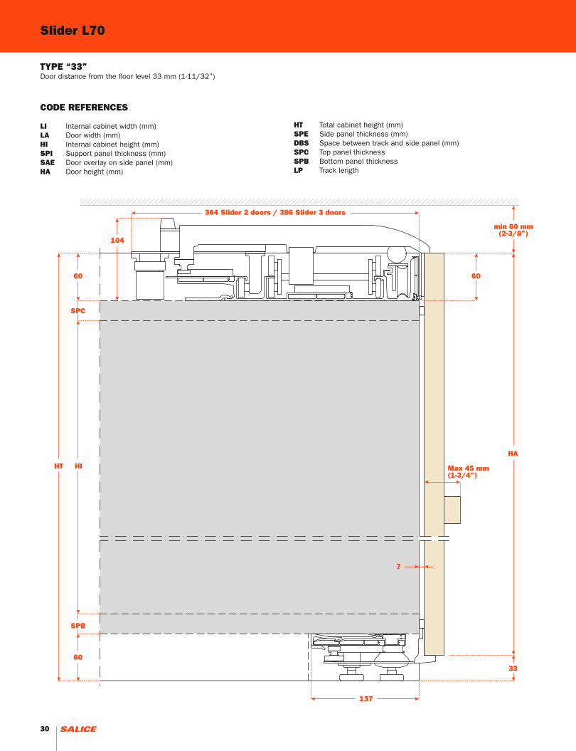
Slider L70
7
60
HI
60
HT
HA
min 60 mm(2-3/8”)
104
364 Slider 2 doors / 396 Slider 3 doors
137
33
60
Max 45 mm(1-3/4”)
SPC
SPB
TYPE “33”Door distance from the floor level 33 mm (1-11/32”)
CODE REFERENCES
LI Internal cabinet width (mm)LA Door width (mm)HI Internal cabinet height (mm)SPI Support panel thickness (mm)SAE Door overlay on side panel (mm)HA Door height (mm)
HT Total cabinet height (mm)SPE Side panel thickness (mm)DBS Space between track and side panel (mm)SPC Top panel thicknessSPB Bottom panel thicknessLP Track length
30

min 19 mm(3/4”)
SPI
min 19 mm(3/4”)
5
DBS + SAE - (SPI/2) + 4.5
LA LA
DBS (max 100 mm) (4”)
SAE(max 25 mm)
(1”)DBS (max 100 mm) (4”)
SAE(max 25 mm)(1”)
LI
LP
Feet supplied with the track.
Additional feet supplied on track (LP) over 2999 mm (118-1/8”).
FLEXIBILITY OF INSTALLATION
The L70 2 doors stock size slider mechanisms can be installed on a carcase which may exceed the dimensions of the track itself by 200 mm (7-7/8”). The protrusion of the door in the open positionis described with the formula: DBS + SAE - (SPI/2) +4.5
31

Section P - P
Item #Mechanism
length(Lp) mm
LiOverlay
(SAE) mmB C D E F G
PackagingClipper frame
Max doorHeight mmWeight
kgDimensions
cm
YE302A1600SA 1599 1600-1800 1 - 25 169 303 154 472 341 - 26 175x46x19 YES 2400
YE302A1800SA 1799 1800-2000 1 - 25 169 353 204 522 391 - 29.4 195x46x19 YES 2400
YE302A2000SA 1999 2000-2200 1 - 25 169 403 254 572 441 - 32.8 215x46x19 YES 3000
YE302A2200SA 2199 2200-2400 1 - 25 169 453 304 622 491 - 36.2 235x46x19 YES 3000
YE302A2400SA 2399 2400-2600 1 - 25 169 503 354 672 541 - 39.6 255x46x19 YES 3000
YE302A2600SA 2599 2600-2800 1 - 25 219 503 354 722 591 425 41.2 275x46x19 YES 3000
YE302A2800SA 2799 2800-3000 1 - 25 269 503 354 772 641 475 43.4 295x46x19 YES 3000
YE302A3000SA 2999 3000-3200 1 - 25 319 503 354 822 691 525 46.8 315x46x19 YES 3000
YE302A3200SA 3199 3200-3400 1 - 25 369 503 354 872 741 575 49.2 335x46x19 NO 3000
YE302A3400SA 3399 3400-3600 1 - 25 419 503 354 922 791 625 51.9 355x46x19 NO 3000
YE302A3600SA 3599 3600-3800 1 - 25 469 503 354 972 841 675 54.6 375x46x19 NO 3000
YE302A3800SA 3699 3800-4000 1 - 25 519 503 354 1022 891 725 57.3 395x46x19 NO 3000
73
40
min 19 mm(3/4”)
LA = (LI/2) + SAE -2.5
HA=HT-33
ø4x10
ø4x10
25
25
B 94C D
E G
F 32
9
max 45 mm(1-3/4”)
98
134
114
25.5
28 R4
P
P
ø2.5x10
Ø8x13
ø8x13ø2.5x10
45
14 159
R4
Q
Q9
57
39
R4
R
R
36 70 70 36
212
189
12
20
S
S
21
14
max 45 mm(1-3/4”)
R4
9
57
Slider L70 - Product codes and assembly specifications LEFT DOOR
Section Q - Q Section R - R
Section S - S
Left DoorInner side of the door
Inner side of the door
32

Section P - P
73
40
min 19 mm(3/4”)
LA = (LI/2) + SAE -2.5
HA=HT-33
Ø4x10
Ø4x10
25
25
B94 CD
EG
F32
9
max 45 mm(1-3/4)
134114
26
28R4
P
P
ø2,5x10
Ø8x13
ø2,5x10Ø8x13
14 98
45
159
R4
Q
Q9
57
39
R4
R
R9
57
36707036
212
189
14
21 1220
R4
S
S
max 45 mm(1-3/4”)
Product codes and assembly specifications RIGHT DOOR
CODE REFERENCES
LI Internal cabinet width (mm)LA Door width (mm)HI Internal cabinet height (mm)SPI Support panel thickness (mm)SAE Door overlay on side panel (mm)HA Door height (mm)B/C/D/E/F/G See chart
As you are in the design phase it will be important to determine the weight of your doors and provide for it with adequate panels thickness.
Section Q - QSection R - R
Section S - S
Right DoorInner side of the door
Inner side of the door
33

34

Pocket Door System
35
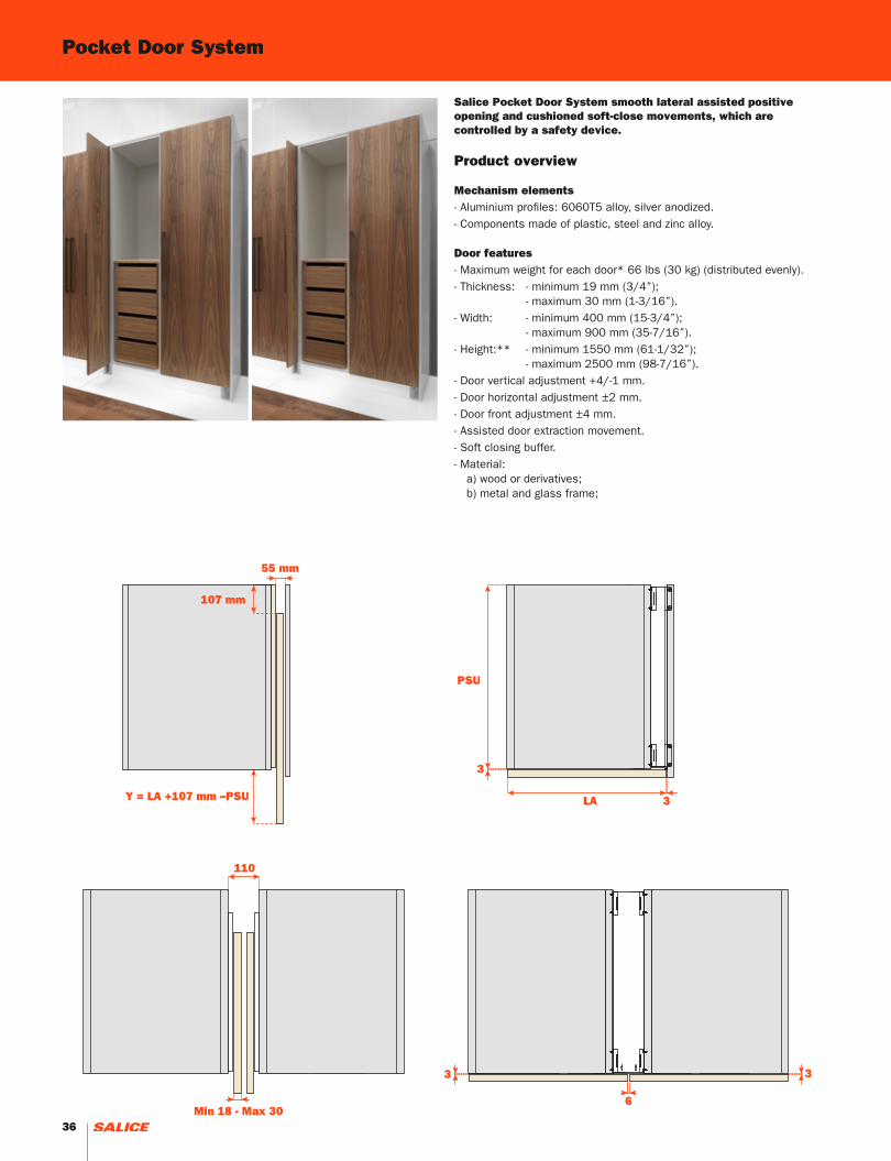
Pocket Door System
Salice Pocket Door System smooth lateral assisted positive opening and cushioned soft-close movements, which are controlled by a safety device.
Product overview
Mechanism elements- Aluminium profiles: 6060T5 alloy, silver anodized.- Components made of plastic, steel and zinc alloy.
Door features- Maximum weight for each door* 66 lbs (30 kg) (distributed evenly).- Thickness: - minimum 19 mm (3/4”); - maximum 30 mm (1-3/16”).- Width: - minimum 400 mm (15-3/4”); - maximum 900 mm (35-7/16”).- Height:** - minimum 1550 mm (61-1/32”); - maximum 2500 mm (98-7/16”).- Door vertical adjustment +4/-1 mm.- Door horizontal adjustment ±2 mm.- Door front adjustment ±4 mm.- Assisted door extraction movement.- Soft closing buffer.- Material: a) wood or derivatives; b) metal and glass frame;
Y = LA +107 mm –PSU
107 mm
3
3
110
Min 18 - Max 306
3 3
PSU
LA
55 mm
Y = LA +107 mm –PSU
107 mm
3
3
110
Min 18 - Max 306
3 3
PSU
LA
55 mm
36

1
1
2
3
4
4
5
6
7
7
1 Patented cam movement with assisted door insertion and extraction.
2 Soft closing buffer.
3 Mounting with clips to facilitate extraction of the mechanism in case of maintenance.
4 Sliding carriage.
5 Quick coupling hinges.
6 Front adjustments on the hinge coupling column.
7 Profile cover caps (included in the standard versions).
37

Calculating the minimum structure dimensions
PSU* (mm)
400-500 501-600 601-700 701-800 801-900
HA
(m
m)
Min Max Min Max Min Max Min Max Min Max
1546 1696 1668 1757 1790 1879
1697 2091 1758 2152 1880 2213 2002 2274 2124 2335
2092 2500 2153 2500 2214 2500 2275 2500 2336 2500
3 x max 18 kg
4 x max 24 kg
5 x max 30 kg
PSU* =Utilised Depth of Cabinet Structure PS** =Depth of Cabinet Structure
Cod. HA (mm) Kg Mc mm
YE55AAD2500SA Right
1550 - 2500 16 0.09 415 x 105 x 2600
YE55AAS2500SA Left
RL
The mechanism is cut to size based to desired length and delivered partially assembled. A cam-carriage connection (tab. 1) must be ordered together with the mechanism kit (tab. 2) according to the utilized depth of the cabinet structure (PSU) and the height of the door (HA). Refer to the installation manual for the assembly operations.
Mechanism KIT (tab.2)
Cam-carriage connection (tab.1)
Cod. PSU (mm) HA (mm) (kg) (mc) (mm)
x 2
max 3 max 4 max 5
YE55KIT0101 400-500 1546 1697 2092 0.65 0.001 285x40x100
YE55KIT0102 501-600 1668 1758 2153 0.80 0.001 285x40x100
YE55KIT0103 601-700 1790 1880 2214 1.00 0.001 285x40x100
YE55KIT0104 701-800 2002 2275 1.25 0.001 405x40x100
YE55KIT0105 801-900 2124 2336 1.50 0.001 405x40x100
Pocket Door System
38

HA
LA
PSU
LP
PS
Y 107 mm
HA
LA
PSU
LP
PS
Y = LA +107 mm –PSU 107 mm
HA
LA
PSU
LP
PS
Y 107 mm
HA
LA
PSU
LP
PS
Y = LA +107 mm –PSU 107 mm
PS* ≥LAPS* <LA
PSU = LA
Y = 107
PSU = PS
HA
LA
PSU
LP
PS
Y 107 mm
HA
LA
PSU
LP
PS
Y = LA +107 mm –PSU 107 mm
HA
LA
PSU
LP
PS
Y 107 mm
HA
LA
PSU
LP
PS
Y = LA +107 mm –PSU 107 mm
HA
LA
PSU
LP
PS
Y 107 mm
HA
LA
PSU
LP
PS
Y = LA +107 mm –PSU 107 mm
HA
LA
PSU
LP
PS
Y 107 mm
HA
LA
PSU
LP
PS
Y = LA +107 mm –PSU 107 mm
CODE REFERENCES
PS Cabinet depthPSU Utilized cabinet depthLA Door widthHA Door heightLP Horizontal profile lengthY External door protrusion
39

Accessories
Structure lateral connection
Cod. PS (mm) (kg) (mc) (mm)
YE55KIT0001 400 - 650 0.85 0.003 90x45x770
YE55KIT0002 650 - 900 1.0 0.004 90x45x1020
YE55KIT0005 400 - 650 0.85 0.003 90x45x770
YE55KIT0006 650 - 900 1.0 0.004 90x45x1020
YE55KIT0003 400 - 650 1.5 0.003 130x45x770
YE55KIT0004 650 - 900 1.8 0.004 130x45x1020
VERSIONE DESTRAVE55KIT0001 - VE55KIT0002
VERSIONE DESTRAVE55KIT0005 - VE55KIT0006
VERSIONE DESTRAVE55KIT0003 - VE55KIT0004
55 mm
55 mm55 mm
110 mm
55 mm
110 mm
VERSIONE DESTRAVE55KIT0001 - VE55KIT0002
VERSIONE DESTRAVE55KIT0005 - VE55KIT0006
VERSIONE DESTRAVE55KIT0003 - VE55KIT0004
55 mm
55 mm55 mm
110 mm
55 mm
110 mm
VERSIONE DESTRAVE55KIT0001 - VE55KIT0002
VERSIONE DESTRAVE55KIT0005 - VE55KIT0006
VERSIONE DESTRAVE55KIT0003 - VE55KIT0004
55 mm
55 mm55 mm
110 mm
55 mm
110 mm
Pocket Door System
40

Magnetic kit for door and structure
Cod. pz (kg) (mc) (mm)
DP39XXG+
DP38XX911 each
0.007
0.0016
DP39XXG16.6 mm x 9.5 mm
DP38XX91
20 mm x 14 mm x 1.5 mm
Cod.L
(m) (kg) (mc) (mm)
YE55KIT0201 2.6 0.7 0.03 100x100x2700
YE55KIT0202 2.6 0.7 0.03 100x100x2700
Accessories
Front cover kit
VERSIONE DESTRAVE55KIT0001 - VE55KIT0002
VERSIONE DESTRAVE55KIT0005 - VE55KIT0006
VERSIONE DESTRAVE55KIT0003 - VE55KIT0004
55 mm
55 mm55 mm
110 mm
55 mm
110 mm
ø 15
41

42

43

Sliding system with vertical gliding for wall cabinets.The mechanism is concealed inside an aluminium profile always hidden from the door.The door moves on two lateral telescopic guides and can be stopped in any position.
Product overview- Vertical sliding system for single door;- Door dimensions: 900 W x 600 H mm (35-7/16”x 23-5/8”) weight from 6 (13lbs) to 8 kg (18 lbs)
1200 W x 600 H mm (47-7/32”x 23-5/8”) weight from 10 (22lbs) to 12 kg (27 lbs)
1800 W x 600 H mm (71-1/16”x 23-5/8”) weight from 15 (33 lbs) to 17 kg (38 lbs)
2400 W x 600 H mm (94-1/2”x 23-5/8”) weight from 19 (42 lbs) to 21 kg (46 lbs)
- Telescopic guides thickness 20 mm;- Height adjustment ± 3 mm (± 1/8”);- Door weight adjustment ± 1 kg (±2 lbs);- 480 mm height door available as special order.
THE KIT ASSEMBLY CONSISTS OF
Horizontal aluminium profile
Pair of full-extension telescopic
guides
Sliding profile for central panel (only
for versions with door from 1800 to
2400 mm)
Packaging with accessories
A
B
C
D E
44

x
y
z
A
B
C
D
B
Insert the aluminium profile (A) on the on the inserts (D) already fixed on the lateral panels
Fix on the lateral panels the support (D) for the aluminium profile
Apply on the front edge of the lateral panels the two telescopic guides with the mounting brackets
Fix the 4 hooks (E) on the internal side of the door
45

ItemTelescopic guide
thicknessmm
Door widthmm
Door weightKg
Packaging
WeightKg
Dimensionscm
YE2809006020 20 900 6-8 5.7 125x10x10
YE2812006020 20 1200 10-12 6.9 125x10x10
YE2818006020 20 1800 15-17 9.9 185x10x10
YE2824006020 20 2400 19-21 10.9 245x10x10
YE2809004820 20 900 5-7 5.4 96x10x10
YE2812004820 20 1200 7-9 6.7 125x10x10
YE2818004820 20 1800 11-13 9.6 185x10x10
YE2824004820 20 2400 16-18 10.6 245x10x10
- Product codes and assembly specifications CABINET
= =
LI19/20 19/2019/20 19/20
X
X Y
Y
ZZ
10
ø14
29ø8
30
16
20
8
13 6
7
A
B
B
A
C
42 73
42R5
44
10 22
12.5
24
4 x ø2.5 12
HT
20
20
29 20
As you are in the design phase it will be important to determine the weight of your doors and provide for it with adequate panels thickness.
Section X - X Section Y - Y
The center panel is required only for door widths1800 and 2400 mm (71-1/16” and 94-3/4”).
Section Z - Z
46

37.5 37.5
LA
25.5
22
E
22
F91.522
91.5
25.5
17
D
32
203
32
89
17
D
32
203
32
89
HA
22 x ø2.5 12
27
18
Product codes and assembly specifications DOOR
As you are in the design phase it will be important to determine the weight of your doors and provide for it with adequate panels thickness.
Drillings are required only for door widths 1800 and 2400 mm (71-1/16” and 94-3/4”).
CODE REFERENCES
LI Internal cabinet width (mm)LA Door width (mm)HA Door height (mm)HT Total cabinet height (mm)A/B/C/D/E/F See chart
Item Description HT LI A B C HA LA D E FWeight
Kg
YE2809006020 900x600 20 mm 600 863 76 224 597 900 224.5 6/8
YE2812006020 1200x600 20 mm 600 1163 76 224 597 1200 224.5 10/12
YE2818006020 1800x600 20 mm 600 1763 76 224 558 597 1800 224.5 733.5 817.5 15/17
YE2824006020 2400x600 20 mm 600 2363 76 224 558 597 2400 224.5 1033.5 1117.5 19/21
YE2809004820 900x480 20 mm 480 863 80 160 477 900 104.5 5/7
YE2812004820 1200x480 20 mm 480 1163 80 160 477 1200 104.5 7/9
YE2818004820 1800x480 20 mm 480 1763 80 160 438 477 1800 104.5 733.5 817.5 11/13
YE2824004820 2400x480 20 mm 480 363 80 160 438 477 2400 104.5 1033.5 1117.5 16/18
47

48

49
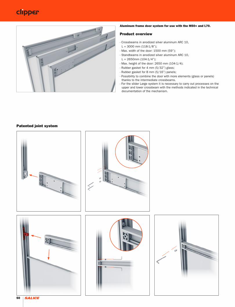
Aluminum frame door system for use with the M50+ and L70.
Product overview
- Crossbeams in anodized silver aluminum ARC 10, L = 3000 mm (118-1/8”);- Max. width of the door: 1500 mm (59”);- Standbeams in anodized silver aluminum ARC 10, L = 2650mm (104-1/4”);- Max. height of the door: 2650 mm (104-1/4);- Rubber gasket for 4 mm (5/32”) glass;- Rubber gasket for 8 mm (5/16”) panels;- Possibility to combine the door with more elements (glass or panels) thanks to the intermediate crossbeams.- For the slider Large system it is necessary to carry out processes on the upper and lower crossbeam with the methods indicated in the technical documentation of the mechanism.
Patented joint system
50

LA
HA
=
=
=
LA = door widthHA = door heightN = number of intermediate profiles
Intermediate profiles length(LA – 26)
Crossbeam lengthHA
Glass (or panel) length (LA – 18.6)
Glass (or panel) height[HA – 8.6 – (3.4 x N)] : (N + 1)
For doors with a whole panel or glass N = 0
Calculation for sizing of the profiles and glass
51

1 Details for assembly of the corners
5 Crossbeam brace
Intermediate crossbeam
2 Details for assemblyof the crossbeams
6 Side standbeam with handle
Side standbeam
3 Elements for application on M50+
7 Rubber gasket for 4 mm glass
Rubber gasket for 8 mm panels
4 Crossbeam for M50+
Crossbean for L70
8 Dust strip
52

3
3
4
8
4
6
1
1
7
2
5
53

Item(mm)
KIT YE43KIT1300
(pz)
Upper and lower crossbeam 3000 1
Concealed intermediate crossbeam 1500 1
Vertical profile without handle 2650 1
Side standbeam with handle 2650 1
Rubber gasket for glass 4 mm 3000 4
Grey brush H7 6000 1
Corner joint kit - 1
Crossbeam joint kit - 1
Screws kit for adjuster - 1
3
4
5
5
6
7
1
2
How to order Clipper frames for Slider L by kitKit for glass door of maximum width 1500 mm.
x 2 x 2 x 4 x 4 x 2
x 4 x 4 x 8 x 8 x 8
x 16
54

Item(mm)
KIT YE43KIT1400
(pz)
KIT YE43KIT1500
(pz)
Junction kit for concealed and dividing intermediate crossbeam 1500 1 -
Rubber gasket for panels 8 mm 3000 - 4
4
6
Optional
Examples
x 2 x 2 x 4 x 4x 2
+
13
6.5
813
6.5
HA
=
=
=
LA
6.5
13
30
13 13
6.5
813
13
6.5
13 13
30
30
30
13
6.5
813
6.5
HA
=
=
=
LA
6.5
13
30
13 13
6.5
813
13
6.5
13 13
30
30
30
3 x YE43KIT1300
Slider L70-Slider L100 3 doors
2 x YE43KIT1300
Slider L100 2 doors
The upper and lower horizontal profiles must be machined as indicated in the technical documentation provided with the mechanism.
55

Item (mm) KIT YE43KIT1200
(pz)
Upper and lower crossbeam 3000 1
Concealed intermediate crossbeam 1500 1
Vertical profile without handle 2650 1
Vertical profile with handle 2650 1
Rubber gasket for glass 4 mm 3000 4
Grey brush H7 6000 1
Grey brush H5 6000 1
Corner joint kit - 1
Crossbeam joint kitQuerstrebe Montage Set - 1
Carriage connector and buffer kit - 1
5
6
7
7
8
9
9
1
2
3
4
How to order Clipper frames for M50+ by kitKit for door with glass of a maximum width of 1500 mm.
x 2 x 2 x 4 x 4 x 2
x 4 x 4 x 8 x 8 x 8
x 2x 2 x 8x 2 x 2 x 8
56

Item (mm)KIT
YE43KIT1400(pz)
KIT YE43KIT1500
(pz)
Junction kit for concealed and dividing intermediate crossbeam 1500 1 -
Rubber gasket for panels 8 mm 3000 - 4
5
7
Optional
Examples
x 2 x 2 x 4 x 4x 2
+
13
6.5
813
6.5
HA
=
=
=
LA
6.5
13
30
13 13
6.5
813
13
6.5
13 13
30
30
30
2 x YE43KIT1200
Slider M35-50 2 doors
57

Lengthmm
ItemPack.pcs.
Dimensionsmm
4 Crossbeam M50+
L = 3000 YE43BTL03000A 2 110x30
4 Crossbeam L70
L = 3000 YE43BTB03000A 2 27x30
5 Bracing crossbeam L = 3000 YE43BTC03000A 2 30x18
5 Intermediate crossbeam
L = 3000 YE43BTD03000A 2 30x30
6 Side standbeam with handle
L = 2650 YE43BTH02650A 2 45x13
6 Side standbeam L = 2650 VE43BTG02650A 2 31x13
PROFILES
RUBBER GASKET
Lengthmm
ItemPack.
pz.Weight
KgVolume
mcDimensions
mm
Rubber gasket for glass 4 mm L = 3000 YE43TAG0500 10 6.8 0.03 110x85x3050
Rubber gasket for panels 8 mm L = 3000 YE43TAG0510 10 5.5 0.03 110x85x3050
Dust strip H 7 mm for M50+
YE43PB4829G 10 2.2 0.02
JOINTS AND PLATES
Lengthmm
ItemPack.
pz.Weight
KgVolume
mcDimensions
mm
Corner joint kit - YE43KIT0001 2 8.3 0.007 290x285x80
Crossbeam joint kit - YE43KIT0002 2 3.9 0.004 240x200x85
Carriage hook up kit M50+ - YE43KIT0006 2 6.8 0.001 330x310x110
Screws kit for adjuster L70 - YE43KIT0005 2 0.45 0.001 125x115x115
x 2
x 8 x 8
x 2 x 4 x 4 x 2
x 4 x 4 x 8 x 8 x 8
x 2 x 2 x 2 x 2
x 16
How to order Clipper frames by item.
58

Notes
59

Ed 0
4 -
06
/20
16
SALICE AMERICA INC.2123 CROWN CENTRE DRIVECHARLOTTE NC. 28227TEL.704 8417810 - 1800 222 9652FAX 704 [email protected]
We reserve the right to change the technical specifications.