
Cop Catalogo Tecnico 2005 IT-EN · Cop Catalogo Tecnico 2005 IT-EN.qxd 20/09/2005 15.46 Page 3. ......
72
CATALOGO TECNICO TECHNICAL CATALOGUE SistemAcciaio Zincato / Decapato Cop Catalogo Tecnico 2005 IT-EN.qxd 20/09/2005 15.46 Page 3
Transcript of Cop Catalogo Tecnico 2005 IT-EN · Cop Catalogo Tecnico 2005 IT-EN.qxd 20/09/2005 15.46 Page 3. ......
C A T A L O G O T E C N I C OT E C H N I C A L C A T A L O G U E
S i s t e m A c c i a i oZ i n c a t o / D e c a p a t o
Cop Catalogo Tecnico 2005 IT-EN.qxd 20/09/2005 15.46 Page 3

In ACCIAIO DECAPATO - ZINCATO 15/10

ALZANTE SCORREVOLE / LIFT-SLIDE SASH
PORTE A VENTO E AUTOMATICHE / SWING DOORS COMPLEMENTARI / OTHER PROFILES
PORTONI / INDUSTRIAL DOORS
In ACCIAIO DECAPATO - ZINCATO 15/10

pag. 2
X cm
Y cm
S m/m2
A cm2
P kg/m4
Jx cm
Jy cm4
Wx cm3
Wy cm3
PZ - PD 30034.80
3.65
21.55
29.38
7.84
6.17
2.75
4.76
0.28
X cm
Y cm
S m/m2
A cm2
P kg/m4
Jx cm
Jy cm4
Wx cm3
Wy cm3
4.03
3.02
17.3
22.07
5.58
5.13
3.1
4.305
0.24
3001
X cm
Y cm
S m/m2
A cm2
P kg/m4
Jx cm
Jy cm4
Wx cm3
Wy cm3
PZ - PD 30024.80
3.65
19.68
29.44
5.85
6.19
3.366
4.76
0.28
PZ*-PD*
A = area della sezione
P = massa teorica
Jx= momento d’inerzia baricentrico, asse x
Jy= momento d’inerzia baricentrico, asse y
Wx= momento resistente baricentrico, asse x
Wy= momento resistente baricentrico, asse y
x,y= distanza dagli assi baricentrici
S = superficie di rivestimento
PZ
PD
= profilo in acciaio zincato -
=
galvanized steel profiles
profilo in acciaio decapato -
black steel profiles
PZ
PD
*
���
��
�������
��
�
Profili
-3011
-3012
-3013
- profilesProfili
P. 3001
P. 3002
P. 3003
/Sections

pag. 3
X cm
Y cm
S m/m2
A cm2
P kg/m4
Jx cm
Jy cm4
Wx cm3
Wy cm3
PZ - PD
X cm
Y cm
S m/m2
A cm2
P kg/m4
Jx cm
Jy cm4
Wx cm3
Wy cm3
PZ - PD4.80
3.77
19.99
29.51
6.06
6.31
3.3
4.68
0.303
3012
X cm
Y cm
S m/m2
A cm2
P kg/m4
Jx cm
Jy cm4
Wx cm3
Wy cm3
PZ - PD4.80
3.77
21.55
29.51
7.77
6.31
2.774
4.68
0.303
3013
3.33
17.42
21.95
5.71
5.16
3.05
4.25
0.26
30114.24
���
��
�������
��
�
Profili
-3011
-3012
-3013
- profilesProfili
P. 3011
P. 3012
P. 3013
/Sections

pag. 4
PZ
PD
= profilo in acciaio zincato -
=
galvanized steel profiles
profilo in acciaio decapato -
black steel profiles
PZ
PD
*
X cm
Y cm
S m/m2
A cm2
P kg/m4
Jx cm
Jy cm4
Wx cm3
Wy cm3
PZ - PD 31024.00
3.00
14.00
9.35
4.16
2.70
3.370
3.485
0.23
X cm
Y cm
S m/m2
A cm2
P kg/m4
Jx cm
Jy cm4
Wx cm3
Wy cm3
PZ - PD4.00
3.00
16.20
9.35
4.80
3.40
3.370
2.75
0.23
3103
3101
X cm
Y cm
S m/m2
A cm2
P kg/m4
Jx cm
Jy cm4
Wx cm3
Wy cm3
PZ - PD
2.6
11.85
5.95
3.95
1.90
3.00
3.18
0.19
3.30
A = area of cross section
P = calculated mass
Jx= x axis moment of inertia, about the center of gravity
Jy= y axis moment of inertia, about the center of gravity
Wx=
Wy= y
x,y= distance from the axes of the center of gravity
S = surface area of coating
x axis moment of resistance, about the center of gravity
axis moment of resistance, about the center of gravity
���
��
�������
��
�
Profili
-3011
-3012
-3013
- profilesProfili
P. 3101
P. 3102
P. 3103
/Sections

pag. 5
3112
X cm
Y cm
S m/m2
A cm2
P kg/m4
Jx cm
Jy cm4
Wx cm3
Wy cm3
PZ - PD 31113.50
2.75
11.85
5.70
3.90
1.8
3.04
3.130
0.21
X cm
Y cm
S m/m2
A cm2
P kg/m4
Jx cm
Jy cm4
Wx cm3
Wy cm3
PZ - PD 31124.00
3.1
14.20
9.00
4.20
2.63
3.38
3.42
0.25
X cm
Y cm
S m/m2
A cm2
P kg/m4
Jx cm
Jy cm4
Wx cm3
Wy cm3
PZ - PD 31134.00
3.1
16.00
9.00
5.77
2.63
3.38
2.770
0.25
���
��
�������
��
�
Profili
-3011
-3012
-3013
- profilesProfili
P. 3111
P. 3112
P. 3113
/Sections

pag. 6
X cm
Y cm
S m/m2
A cm2
P kg/m4
Jx cm
Jy cm4
Wx cm3
Wy cm3
4.03
3.49
17.5
22.07
5.58
5.13
3.1
4.305
0.24
X cm
Y cm
S m/m2
Wx cm3
Wy cm3
17.95
11.07
7.48
4.76
0.40
A cm2
P kg/m4
Jx cm
Jy cm4
PZ - PD 3005
PZ - PD 3006
6.62
5.50
134.27
33.40
X cm
Y cm
S m/m2
Wx cm3
Wy cm3
A cm2
P kg/m4
Jx cm
Jy cm4
PZ - PD 3004 15.24
10.36
7.13
3.280
0.38
6.11
5.00
108.66
30.85
���
��
�������
��
�
Profili
-3011
-3012
-3013
- profilesProfili
P. 3004
P. 3005
P. 3006
/Sections

pag. 7
PZ - PD 2017Profilo per riporto battente
Peso / = 1.03 kg/m
Lunghezza / = 4 m
Bringhing back bracket
Weight
Lenght
PZ - PD 2018Profilo copri canalino
Peso / = 0.62 kg/m
Lunghezza / = 4 m
Covering profile canalization
Weight
Lenght
PZ 3208Profilo a T commerciale
Peso / = 2.49 kg/m
Lunghezza / = 6 m
Commercial T profile
Weight
Lenght
PZ - PD 3019Profilo centrale inversione battuta
Peso / = 2.17 kg/m
Lunghezza / = 4,5 m
Central profile for double-leafed door
Weight
Lenght
PZ - PD 2020Profilo di raccordo
Peso / = 0.85 kg/m
Lunghezza / = 4 m
Connecting profile
Weight
Lenght
PZ - PD 2021Profilo angolare curvo
Peso / = 1.30 kg/m
Lunghezza / = 4 m
Angolar bend profile
Weight
Lenght
���
��
�������
��
�
Profili
-3011
-3012
-3013
- profilesProfili
complementari
Other sections

PZ - PD 3140Profilo di riporto per zoccolo
Peso / = 2.70 kg/m
Lunghezza / = 6 m
Additional profile under socle
Weight
Lenght
PZ - PD 3141Profilo battuta centrale
Peso / = 1.80 kg/m
Lunghezza / = 4 m
Central ledge
Weight
Lenght
PZ - PD 3143Profilo telaio esterno superiore e laterale alzante scorrevole
Peso / = 6.90 kg/m
Lunghezza / = 6 m
Superior and lateral frame profile for lift and slide door
Weight
Lenght
3144Profilo telaio esterno inferiore alzante scorrevole
Peso / = 6.15 kg/m
Lunghezza / = 6 m
Inferior frame profile for lift and slide door
Weight
Lenght
PZ - PD 3144
pag. 8
���
��
�������
��
�
01
02
03
nsProfili
-3011
-3012
-3013
- profilesProfili alzante
scorrevole
Lift and slide
door sections
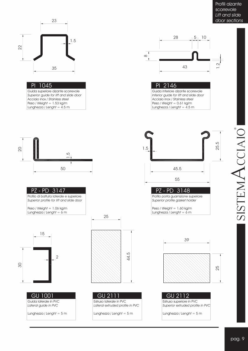
PI 1045Guida superiore alzante scorrevole
Acciaio inox
Peso / = 1.53 kg/m
Lunghezza / = 4.5 m
Superior guide for lift and slide door
/ Stainless steel
Weight
Lenght
PI 2146
PZ - PD 3147Profilo di battuta laterale e superiore
Peso / = 1.06 kg/m
Lunghezza / = 6 m
Superior profile for lift and slide door
Weight
Lenght
PZ - PD 3148Profilo porta guarnizione superiore
Peso / = 1.60 kg/m
Lunghezza / = 6 m
Superior profile gasket holder
Weight
Lenght
GU 1001Guida laterale in PVC
Lunghezza / = 5 m
Lateral guide in PVC
Lenght
Guida inferiore alzante scorrevole
Acciaio inox
Peso / = 0.61 kg/m
Lunghezza / = 4.5 m
Inferior guide for lift and slide door
/ Stainless steel
Weight
Lenght
GU 2111Estruso laterale in PVC
Lunghezza / = 5 m
Lateral extruded profile in PVC
Lenght
GU 2112Estruso superiore in PVC
Lunghezza / = 5 m
Superior extruded profile in PVC
Lenght
pag. 9
���
��
�������
��
�
Profili
-3011
-3012
-3013
- profilesProfili alzante
scorrevole
Lift and slide
door sections

pag. 10
PZ 2301
PZ - PD 2305Profilo zoccolo per porte a vento
Peso / = 4.67 kg/m
Lunghezza / = 4 m
Socle profile for swing door
Weight
Lenght
PZ 2302
Profilo di riporto porta spazzolino
Peso / = 0.64 kg/m
Lunghezza / = 3 m
Adjuntive profile brushing hander
Weight
Lenght
PZ 2303Profilo porta spazzolino sotto zoccolo
Peso / = 0.51 kg/m
Lunghezza / = 3 m
Brushing hander profile under socle
Weight
Lenght
Profilo finitura laterale
Peso / = 0.51 kg/m
Lunghezza / = 3 m
Lateral finishing profile
Weight
Lenght
���
��
�������
��
�
Profili
-3011
-3012
-3013
- profilesProfili
-3011
-3012
-3013
- profilesProfili
porte a vento
Swing doors
sections

pag. 11
PZ 0014Profilo finitura porta guarnizione
Peso / = 1.90 kg/m
Lunghezza / = 4.6 m
Gasket holder finishing profile
Weight
LenghtPZ 0016
Profilo per asta cariglione
Peso / = 0.69 kg/m
Lunghezza / = 6 m
Lever handle profile
Weight
Lenght
PZ 0021Guida per rullino deviatore
Peso / = 1.76 kg/m
Lunghezza / = 4,6 m
Guide for deviation roll
Weight
Lenght
PZ 1030Guida superiore per portoni alibro
Peso / = 3.00 kg/m
Lunghezza / = 6 m
F uperior guide
Weight
Lenght
olding industrial door s
PZ 0034Guida inferiore per portoni industriali
Peso / = 1.94 kg/m
Lunghezza / = 6 m
Folding industrial door inferior guide
Weight
Lenght
���
��
�������
��
�
Profili
-3011
-3012
-3013
- profilesProfili portoni
industriali
Industrial
door sections
pag. 12
���
��
�������
��
�
Profili
-3011
-3012
-3013
- profilesProfili
-3011
-3012
-3013
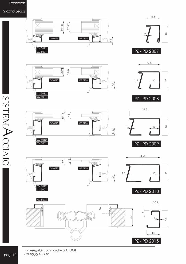
- profilesFermavetri
Glazing beads
P.----PI 1045P.----
PZ - PD 2007
P.----PI 1045P.----GP 0095 GP 0106
PI 1045GP 0095 GP 0106
PI 1045GP 0095 GP 0106
PI 1045GP 0095 GP 0106
CV 5012
CV 5001
CV 5012
CV 5001
CV 5012
CV 5001
CV 5012
CV 5001
AC 5023
Fori eseguibili con maschera AT 5001
Drilling jig AT 5001
P.----PI 1045PZ - PD 2008
P.----PI 1045PZ - PD 2009
PI 1045PZ - PD 2010
PI 1045PZ - PD 2015
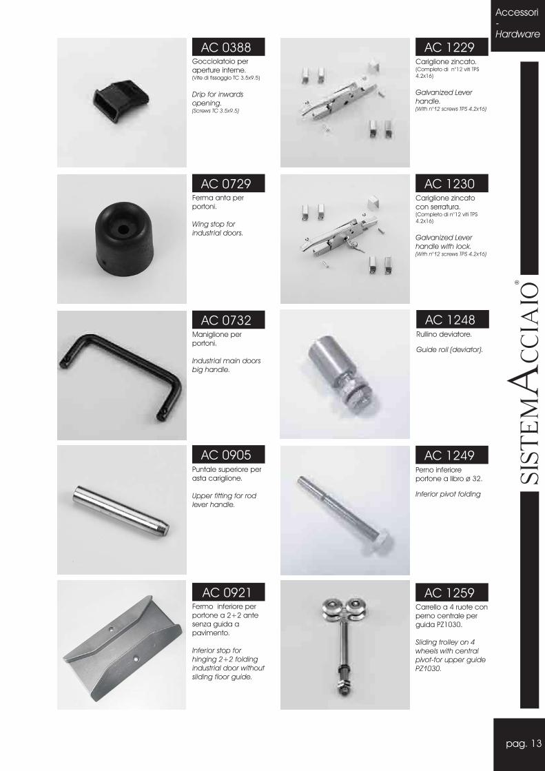
Gocciolatoio per
aperture interne.(Vite di fissaggio TC 3.5x9.5)
Drip for inwards
opening.(Screws TC 3.5x9.5)
AC 0388 AC 1229
AC 1230
AC 1249
AC 1248
AC 1259
Ferma anta per
portoni.
Wing stop for
industrial doors.
Perno inferiore
portone a libro ø 32.
Inferior pivot folding
Rullino deviatore.
Guide roll (deviator).
Carrello a 4 ruote con
perno centrale per
guida PZ1030.
Sliding trolley on 4
wheels with central
pivot-for upper guide
PZ1030.
Cariglione zincato.(Completo di n°12 viti TPS
4.2x16)
Galvanized Lever
handle.(With n°12 screws TPS 4.2x16)
Cariglione zincato
con serratura.(Completo di n°12 viti TPS
4.2x16)
Galvanized Lever
handle with lock.(With n°12 screws TPS 4.2x16)
AC 0729
Maniglione per
portoni.
Industrial main doors
big handle.
AC 0732
Puntale superiore per
asta cariglione.
Upper fitting for rod
lever handle.
AC 0905
Fermo inferiore per
portone a 2+2 ante
senza guida a
pavimento.
Inferior stop for
hinging 2+2 folding
industrial door without
sliding floor guide.
AC 0921
pag. 13
���
��
�������
��
�
Distindi tag
Po
Accessori-Hardware

AC 5001
Cerniera a due ali in
acciaio zincato con
cuscinetto 20.�
Two wings hinge, to
be welded in
galvanized steel with
bearing 20.�
AC 5001
Fioretto sinistro in
acciaio , per
inversione di battuta.
zincato
Left drill in galvanized
steel.
AC 5004
Serratura multipunto
scrocco con
catenaccio.(Completa di viti)
Three point spring
bolt lock+ latch and
couple of vertical
rod.(With screws)
AC 5005
Coppia di maniglie in
acciaio inox
complete di viti.
Stainless steel couple
handle with screws.
Fioretto destro in
acciaio zincato, per
inversione di battuta.
Right drill in
galvanized steel.
AC 5002
AC 5003
Serratura multipunto
rullo con catenaccio.(Completa di viti)
Three point lock +
latch and couple of
vertical rod.(With screws)
AC 5001AC 5006
Serratura normale
scrocco con
catenaccio. (Completa
di viti)
Standard spring bolt
lock latch. (With screws)
AC 5007
Coppia aste verticali
per serratura normale.
Couple of vertical
rods for standard
lock.
AC 5010
Serratura normale
rullo con
catenaccio.(Completa
di viti)
Standard bolt lock
latch. (With screws)
AC 5008
Elettroserratura
normale. (Completa di
viti)
Standard electric
lock. (With screws)
AC 5009
Catenaccio in lega.(Completa di viti).
Door bolt.(With screws)
AC 5011
Guida laterale per
impacchettamento
ante dx.
Lateral guide for wing
folding right.
AC 3471
Guida laterale per
impacchettamento
ante sx.
Lateral guide for wing
folding left.
AC 3470
AC 1260Carrello a 4 ruote con
perno laterale, per
guida PZ1030.
Sliding trolley on 4
wheels with side
pivot-for upper guide
PZ1030.
pag. 14
���
��
�������
��
�
Distintedi taglio
-Porte
Accessori-
Hardware
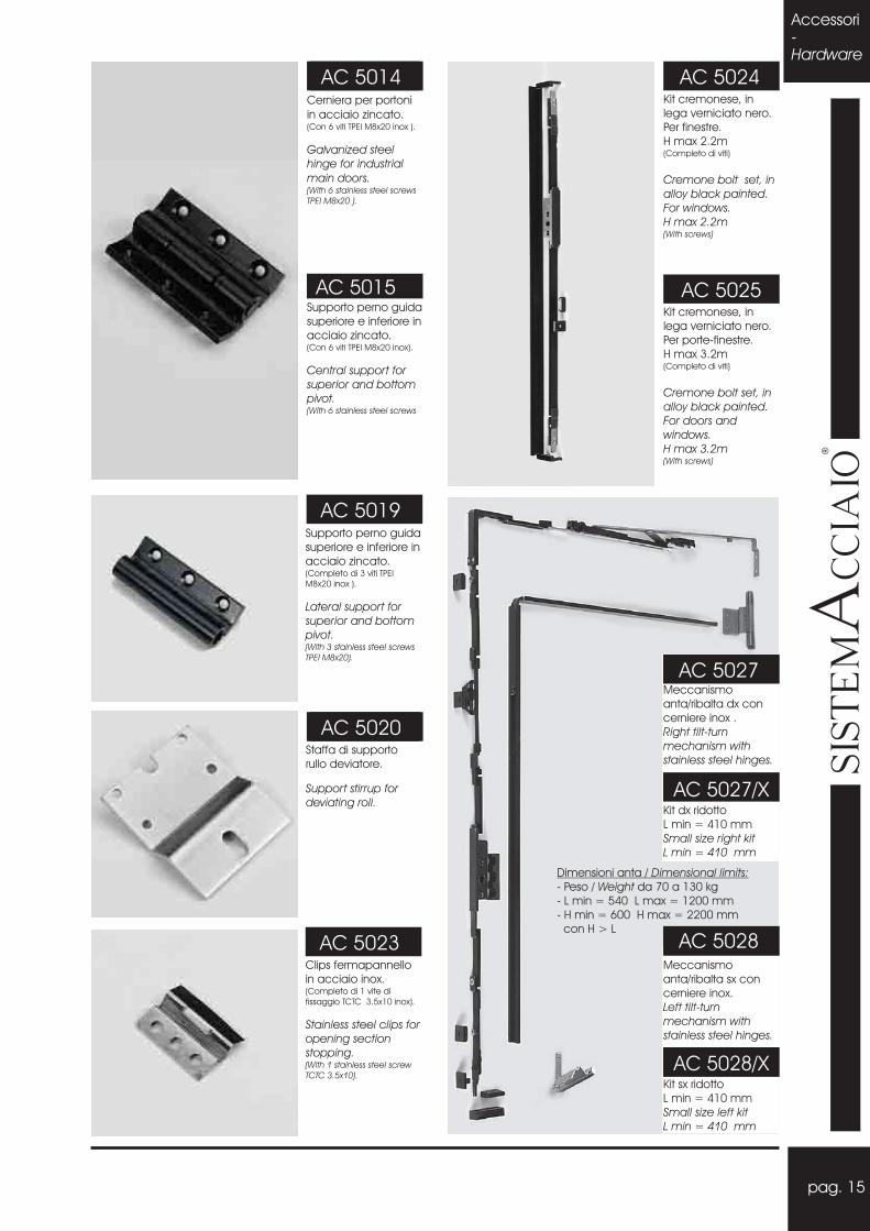
AC 5001Cerniera per portoni
in acciaio zincato.(Con 6 viti TPEI M8x20 inox ).
Galvanized
(With 6 screws
TPEI M8x20 ).
steel
hinge for industrial
main doors.stainless steel
AC 5014
Supporto perno guida
superiore e inferiore in
acciaio zincato.(Con 6 viti TPEI M8x20 inox).
Central s
(With 6 screws
upport for
superior and bottom
pivot.stainless steel
AC 5015
AC 5001AC 5020
Supporto perno guida
superiore e inferiore in
acciaio zincato.(Completo di 3 viti TPEI
M8x20 inox ).
(With 3 stainless steel screws
TPEI M8x20).
Lateral support for
superior and bottom
pivot.
Clips fermapannello
in acciaio inox.(Completo di 1 vite di
fissaggio TCTC 3.5x10 inox).
(With 1 stainless steel screw
TCTC 3.5x10).
Stainless steel clips for
opening section
stopping.
AC 5023
AC 5019
Staffa di supporto
rullo deviatore.
Support stirrup for
deviating roll.
Kit cremonese, in
lega verniciato nero.
Per finestre.
H max 2.2m(Completo di viti)
H max 2.2m
Cremone bolt set, in
alloy black painted.
For windows.
(With screws)
AC 5024
AC 5025Kit cremonese, in
lega verniciato nero.
Per porte-finestre.
H max 3.2m(Completo di viti)
H max 3.2m
Cremone bolt set, in
alloy black painted.
For doors and
windows.
(With screws)
Meccanismo
anta/ribalta dx con
cerniere inox .
Right tilt-turn
mechanism with
stainless steel hinges.
AC 5027
Dimensioni anta / Dimensional limits:
-
L min = 540 L max = 1200 mm
- H min = 600 H max = 2200 mm
con H > L
Peso / da 70 a 130 kg
-
Weight
Kit dx ridotto
L min = 410 mm
Small size right kit
L min = 410 mm
AC 5027/X
AC 5028/X
AC 5028Meccanismo
anta/ribalta sx con
cerniere inox.
Left tilt-turn
mechanism with
stainless steel hinges.
Kit sx ridotto
L min = 410 mm
Small size left kit
L min = 410 mm
pag. 15
���
��
�������
��
�
Distindi tag
Po
Accessori-Hardware

Coppia limitatori di
apertura vasistas in
acciaio Inox. (Completi
di 8 viti TC 4.2x9.5 inox).
Couple of casement
stay in stainless steel
for bottom hinged
window.(With 8 stainless steel screws
TC 4.2x9.5).
Cerniera in acciaio
ad avvitare per porte
a due ali, verniciata
nera.(Completa di viti TCEI M8x25
e inserti filettati M8).
Two wings steel hinge
for door, colour black.(With screws TCEI M8x25, and
threaded inserts M8).
Peso max anta 80 kg
Door weight up to 80 kg
AC 5030
AC 5031
AC 5032
AC 5037
Cerniera a 2 ali da
avvitare , in acciaio
zincato per finestre.(Completa di viti
inox).
TC 4.2x12.7
(With 8 screws TC
4.2x12.7).
stainless steel
Hinge to be screwed,
two wings in galvanized
steel for windows.
AC 5029 AC 5039
Cricchetto da avvitare
in lega e nylon nero
con incontro in
acciaio inox.(Completo di 2 viti TCEI 4.8x16;
2 viti TPS 3.9x13).
stainless steel(With 2 screws TCEI 4.8x16; 2
screws TPS 3.9x13).
Catch detent to be
screwed in nylon,
black colour,
complete with
plate.
AC 5040
AC 5041Kit chiusura
supplementare anta
ribalta su lato cerniere.
Altezza anta > 1200
mm
Tilt and turn additional
kit locking for hinge
side
Leaf height> 1200 mm
AC 5042
Maniglia con incontro
in lega colore nero
per apertura a
sporgere.(Completa di viti di fissaggio).
(Complete fixing screws).
Handle with the alloy
black painted or in
the PVC hardware.
Kit chiusura 2° anta
finestra
Second leaf locking
kit for windows
Coppia compassi per
persiana in acciaio
inox.(Completi di 12 viti di
fissaggio TC 4.8x13 inox).
(With 12 fixing screws TC
4.8x13 in stainless steel).
Couple of side arms
in stainless steel.
Braccio
supplementare per
anta ribalta
Larghezza anta >
1200 mm
Additional arm dual
porpose
Leaf lenght > 1200
mm
AC 5043
Cerniera in acciaio
ad avvitare per porte
a tre ali, verniciata
nera.(Completa di viti TCEI M8x25 e
inserti filettati M8).
Three wings steel
hinge for door, colour
black.(With screws TCEI M8x25, and
threaded inserts M8).
Peso max anta 150 kg
Door weight up to 150 kg
Limiti dimensionali /
Peso anta / : 50 kg
Larghezza anta / : 1 m
Dimensional limits:
weightLeaf
Leaf lenght
Limiti dimensionali /
Peso anta / : 50 kg
Altezza anta / : min 320
Dimensional limits:
Leaf weight
Leaf height
Limiti dimensionali /
Peso anta / : 75 kg
Altezza anta / : min 800 mm
Dimensional limits:
weightLeaf
Leaf height
pag. 16
���
��
�������
��
�
Distintedi taglio
-Porte
Accessori-
Hardware

AC 6006Cerniera regolabile a
tre ali da avvitare.(Completa di 2 viti TSPEI
M.8x20 inox , 3 viti TB M.6x14
inox e inserti filettati).
Adjustable three wing
hinge to be screwed(whit threaded inserts and 2
screws TSPEI M.8x20 , 3 screws
TB M.6x14)
AC 6020Coppia di snodi a
frizione con fermo per
bilico.
Portata anta:
60 kg
100 kg con rinforzo
Couple of friction
joints with stop for
pivot.
Leaf weight:
60 kg
100 kg rinforced
AC 6045Cerniera a tre ali da
avvitare in acciaio
zincato, per profili
ridotti.(Completo di viti TSPEI
M.5x10; TCEI M5x8).
Three fin hinge in
galvanized steel , for
reduced profiles(Complete with oxidated
TSPEI M.5x10,TCEI M5x8).
AC 6007 iPiastrina di aggancio
per
P.2301/P.2302/P.3019
Joint plate for
P.2301/P.2302/P.3019
AC 6049 i
pag. 17
Limiti dimensionali /
Peso anta / : 70 kg
Dimensional limits:
Leaf weight
���
��
�������
��
�
Portata massima/ 100 kgMax. weight=
Distindi tag
Po
Accessori-Hardware
Maniglia DK per
cremonese in acciaio
inox scotch brite
Handle DK for
cremone bolt, in
.
scotch brite stainless
steel
AC 5056Kit sx per scorrevole
parallelo e ribalta.
Left parallel tilt and
slide mechanism.
AC 6051.Kit destro
Right mechanism.
Larghezza anta/
AC 605../1 590 - 890
Wing lenght
AC 605../2 891 -1040
AC 605../3 1041-1240
AC 605../4 1241-1440
AC 605../5 1441-1640
Portata massima/
150 kg
L x H =
590 x 600 mm
Maximum weight
min min
L x H =
1640 x 2300 mm
max max
Kit per alzante
scorrevole.
(Specificare all’ordine
misure anta)
Left and slide unit.
(Leaf measures to be
specify once
ordered)
AC 6148
AC 6119Fondino di testa per
P. 3019
Terminal cup for
P. 3019
Puntale inferiore per
asta cariglione.
Bottom fitting for rod
lever handle.
AC 8764
Portata massima/
250 kg
L x H =
720 x 1175 mm
Maximum weight
min min
L x H =
3350 x 2675 mm
max max
AC 6056Cerniera a
scomparsa
registrabile in acciaio(Completa di viti)
Concealed hinges
for steel door in steel(With screws)
Portata massima/ 160 kg
Apertua
Max. weight=
massima/Max. opening=96°
Boccola per fermavetri.
Bushings for glazing
beads.
CV 5012
AT 5001Vite per boccola
fermavetri .TPS 4,2 x16
Screw for
bushing TPS 4,2 x16.
glazing bead
CV 5001
AC 5056

pag. 18
���
��
�������
��
�
Distintedi taglio
-Porte
Guarnizioni-
Weatherstrip
Guarnizione per
portoni industriali -
0,38kg/m
Weather strip for main
industrial doors - 0,38
kg/m
Guarnizione di battuta
a palloncino.
Weather strip for
rabbet.
Guarnizione di battuta
con aletta.
Weather strip for
rabbet with fin.
GE 2001
Guarnizione interna
fermavetro, spessore 3
mm.
Weather strip for
internal use on glazing
bead of thickness 3
mm.
GP 0095
Guarnizione interna
fermavetro, spessore 6
mm.
Weather strip for
internal use on glazing
bead of thickness 6
mm.
GP 0106
Estruso porta
spazzolino per porte.
Extruded PVC for
brushing for door.
Spazzolino per porte,
su GU 0120
Brushing for doors, on
GU 0120.
H= 5 mm
Spazzolino per portoni.
Brushing h 50 mm
with support for
industrial door.
H = 50 mm
GU 0142
GP 0010
GE 0013
GU 0002Guarnizione di tenuta
per alzante scorrevole.
Weather strip for lift
and slide door.
GE 1048Guarnizione centrale
di battuta per alzante
scorrevole.
Central weather strip
for lift and slide door.
Guarnizione per
portoni industriali
- 0.41 Kg/m.
Weather strip for main
industrial door - 0,41
Kg/mt.
GE 0013
HSP
AZZ
OLI
NO
Guarnizione di tenuta
laterale e superiore
per alzante scorrevole.
Lateralal and superior
weather strip for left
and slide door.
GU 0100
GU 0120
GU 0087GE 2000

AC 5001Stampo esecuzione
fori scarico acqua
Dig for execution of
holes of water drip.
/ Press :
Tons
Pressa
5 Tonnellate /
AT 2023
STAMPI E ATTREZZATURE DIE AND EQUIPEMENT-
TSPEI Philips flat hex socket cap
TPEI
TCTC
TPS
Flat head socket head screw
Pan head philips
Philips flat cap
TC
TCEI
Pan head
Hex socket head cap screw
TIPOLOGIE DI VITI SCREWS TIPOLOGIES
Testa Cilindrica
Testa Cilindrica Esagono Incassato
Testa Piana Esagono Incassato
Testa Cilindrica Taglio Croce
Testa Piana Svasata
Testa Svasata Piana Esagono Incassato
AT 2002Maschera per
esecuzione fori
fissaggio cerniere
AC 6006 e AC 6045
Jig for execution of
holes for fixing hinges
AC 6006 and AC
6045
Stampo per spacchi
e fori applicazione
meccanismo
cremonese e anta
ribalta
Jig for execution
holes for tilt-turn and
cremon mechanism
Pressa
10 Tonnellate /
/ Press :
Tons
AT 2024
Maschera per
esecuzione fori di
fissaggio fermavetri.
Jig for execution of
holes of glazing
beads.
fixing
pag. 19
AC 5001Stampo esecuzione
spacco serratura
Dig for execution of
holes for lock
Pressa
10 Tonnellate /
/ Press :
Tons
AT 2203
AC 5001Stampo esecuzione
taglio punte
Jig for execution of
cut for T and Z union
Pressa
5 Tonnellate /
/ Press :
Tons
AT 2204
AC 5001AT 5001
AC 5001AT 5001
AT 2105Ganasce per taglio
profili L,T e Z
maggiorati e ridotti
Cutting jaws for L, T e
Z to 50 or 25 sections. ���
��
�������
��
�
AC 5001Stampo esecuzione
spacco incontri
serratura
Dig for execution of
holes for striking plates
Pressa
10 Tonnellate /
/ Press :
Tons
AT 2202
Attrezzatura
-
Equipment
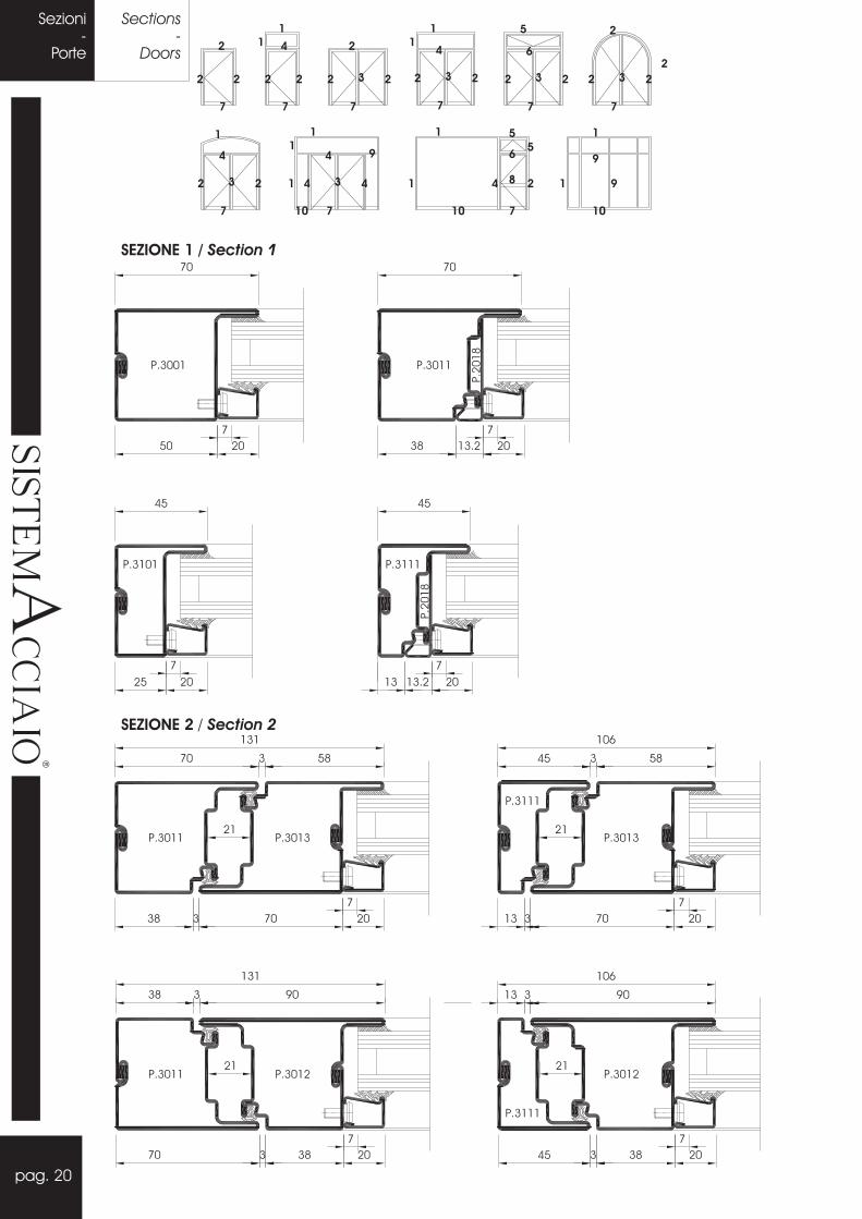
SEZIONE 1 / Section 1
SEZIONE 2 / Section 2
pag. 20
���
��
�������
��
�
Distintedi taglio
-Porte
Sezioni-
Porte
Sections-
Doors2
2
7
4
2
7
2
32
7
2
11
4
32
7
2
6
32
7
2
2
32
7
2
5
2 2
4
32
7
2
1
4
34
7
41
9 6
4
10
21
7
5
10
9
1
1 98
11
11
1 5
10
2

2
2
7
4
2
7
2
32
7
2
11
4
32
7
2
6
32
7
2
2
32
7
2
5
2 2
4
32
7
2
1
4
34
7
41
9 6
4
10
21
7
5
10
9
1
1 98
11
11
1 5
10
SEZIONE 3 / Section 3
SEZIONE 4 / Section 4
pag. 21
���
��
�������
��
�
2
Sections-Doors
Sezioni-Porte

SEZIONE 5 / Section 5
SEZIONE 6 / Section 6
pag. 22
���
��
�������
��
�
Distintedi taglio
-Porte
Sezioni-
Porte
Sections-
Doors2
2
7
4
2
7
2
32
7
2
11
4
32
7
2
6
32
7
2
2
32
7
2
5
2 2
4
32
7
2
1
4
34
7
41
9 6
4
10
21
7
5
10
9
1
1 98
11
11
1 5
10
2

2
2
7
4
2
7
2
32
7
2
11
4
32
7
2
6
32
7
2
2
32
7
2
5
2 2
4
32
7
2
1
4
34
7
41
9 6
4
10
21
7
5
10
9
1
1 98
11
11
1 5
10
SEZIONE 7 / Section 7
SEZIONE 10 / Section 10
SEZIONE 8 / Section 8 SEZIONE 9 / Section 9
pag. 23
���
��
�������
��
�
Sections-Doors
Sezioni-Porte

2
2
2
4
2
2
42
2
2
11 6
4
1
1
2 2
42
2
2
2
4
2
1
1
11
1
2
4
11 5
22
42 2
2
4
31
42 2 44 4
2
21
2
1
1 44 4
5
21
2
SEZIONE 1 / Section 1
SEZIONE 3 / Section 3
SEZIONE 2 / Section 2
SEZIONE 4 / Section 4
pag. 24
���
��
�������
��
�
Sezioni-
Finestre
Sections-
Windows

2
2
2
4
2
2
42
2
2
11 6
3
1
1
2 2
42
2
2
2
4
2
1
1
11
1
2
4
11 5
22
42 2
2
4
31
42 2 44 4
2
21
2
1
1 44 4
5
21
2
SEZIONE 5 / Section 5
SEZIONE 6 / Section 6
pag. 25
���
��
�������
��
�
Sections-Windows
Sezioni-Finestre

pag. 26
SEZIONE 1 / Section 1
SEZIONE 2 / Section 2
���
��
�������
��
�
Sezioni-
Porta avento
Sections-
Swingdoor
3
1
4
1
3
4
1 12

pag. 27
SEZIONE 3 / Section 3
SEZIONE 4 / Section 4
���
��
�������
��
�
Sections-Swingdoor
Sezioni-Porta avento
3
1
4
1
3
4
1 12
pag. 28
���
��
�������
��
�
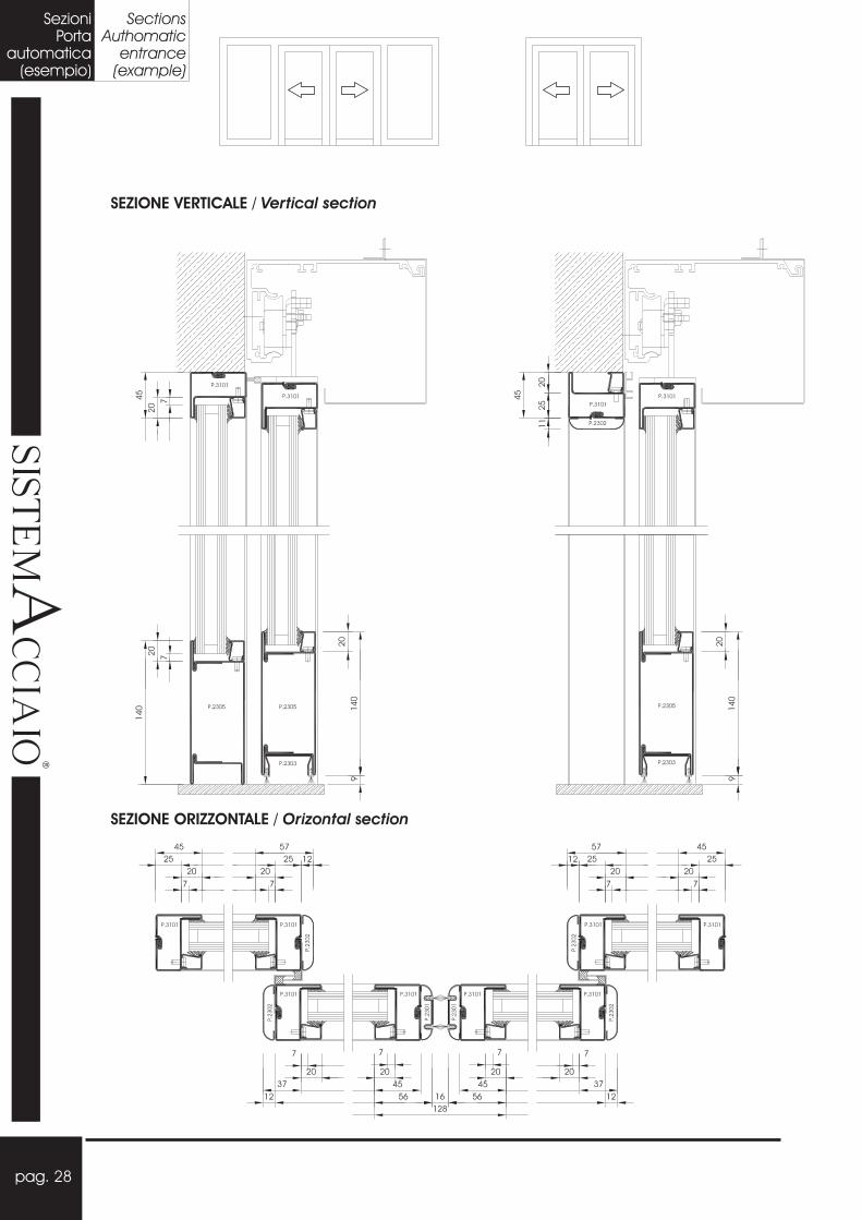
SezioniPorta
automatica(esempio)
SectionsAuthomatic
entrance(example)
SEZIONE VERTICALE / Vertical section
SEZIONE ORIZZONTALE / sOrizontal ection
pag. 29
���
��
�������
��
�
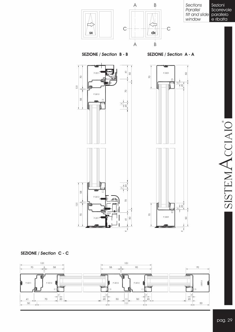
SectionsParalleltilt and slidewindow
SezioniScorrevoleparalleloe ribalta
SEZIONE C - C/ Section
SEZIONE B - B/ Section SEZIONE A - A/ Section
sx dx

pag. 30
���
��
�������
��
�
Sezioni-
Alzantescorrevole
Sections-
Lift andslide door
SEZIONE ORIZZONTALE / sOrizontal ection
SEZIONE VERTICALE / Vertical section

pag. 31
���
��
�������
��
�
Sections-Lift andslide door
Sezioni-Alzantescorrevole
SEZIONE VERTICALE / Vertical section
SEZIONE ORIZZONTALE / sOrizontal ection

pag. 32
SEZI
ON
EB
-B
(va
ria
nte
)/Se
ctio
nSE
ZIO
NE
B-
B/Se
ctio
n
SEZI
ON
EA
-A
/Se
ctio
n
SEZI
ON
EC
-C
/Se
ctio
n
SEZIONE F - F (variante)/ Section
���
��
�������
��
�
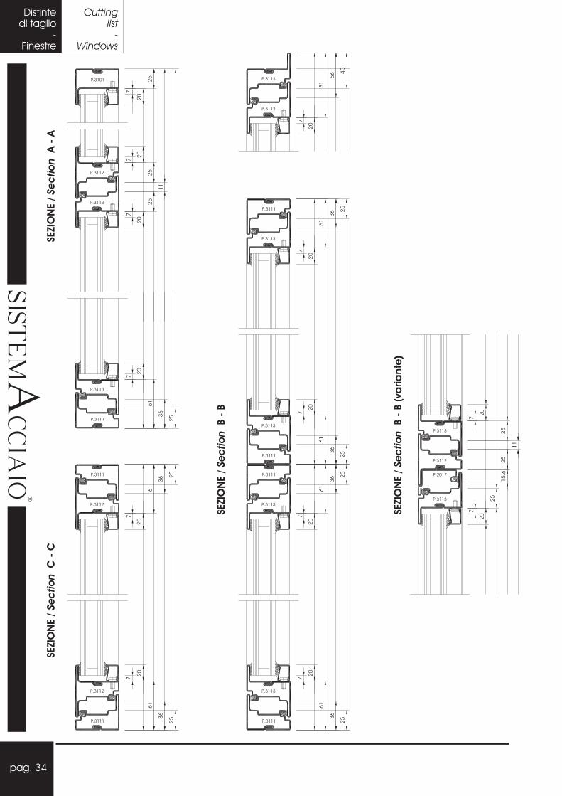
Distintedi taglio
-Porte
Cuttinglist
-Doors

pag. 33
FD D
E E
A
A
B
B
C
C
SEZIONE F - F/ Section
SEZIONE D - D/ Section
SEZIONE E - E/ Section
���
��
�������
��
�
F
Cuttinglist-Doors
Distintedi taglio-Porte
pag. 34
SEZI
ON
EA
-A
/Se
ctio
nSE
ZIO
NE
C-
C/Se
ctio
n
SEZI
ON
EB
-B
/Se
ctio
n
SEZI
ON
EB
-B
(va
ria
nte
)/Se
ctio
n
���
��
�������
��
�
Distintedi taglio
-Finestre
Cuttinglist
-Windows

pag. 35
F FD D
E E
A
A
B
B
C
C
SEZIONE E - E/ Section
SEZIONE D - D/ Section
SEZIONE F - F/ Section
���
��
�������
��
�
N.B. Per la tipologia ad Anta/Ribalta tagliareL’anta 1 mm. più corta.
Cuttinglist-Windows
Distintedi taglio-Finestre

SEZIONE A -A/ Section
SEZIONE B -B/ Section
pag. 36
���
��
�������
��
�
Distintedi taglio
-Bilico
Cuttinglist
-Pivot
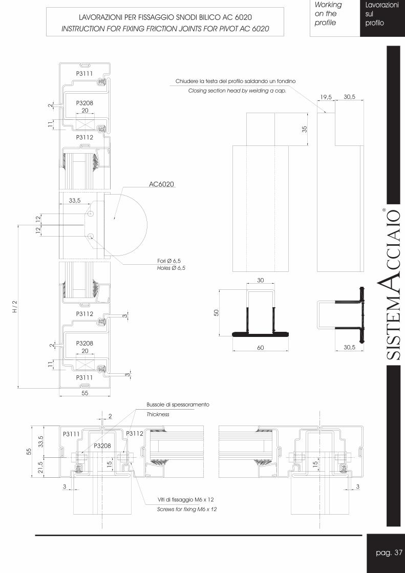
Bussole di spessoramento
Viti di fissaggio M6 x 12
Screws for fixing M6 x 12
Fori Ø 6,5
Holes 6,5Ø
AC6020
Chiudere la testa del profilo saldando un fondino
Closing section head by welding a cap.
Thickness
pag. 37
Lavorazioni
sul
profilo
Working
on the
profileLAVORAZIONI PER FISSAGGIO SNODI BILICO AC 6020
INSTRUCTION FOR FIXING FRICTION JOINTS FOR PIVOT AC 6020
���
��
�������
��
�
P3111
P3208
P3112
P3112
P3208
P3111
P3111 P3112
P3208

Lavorazioni
sul
profilo
pag. 38
Working
on the
profile
N.B. Applicare il sigillante nei perimetri indicati
ed inserire nella feritoia del profilo.
Apply the sealing as indicate, then introduce it
in the hole af the section.
(Asportazione di parte del canalino da
eseguire con pantografo).
(Removal of part of channel to be done by the
pantograph).
N.B. Applicare il sigillante nella feritoia
creatasi con l’asposrtazione del canalino.
Apply sealing in the hole after the
removal of channel.
LAVORAZIONI E SIGILLATURE PER SCARICHI ACQUA APERTURE INTERNE
WORKING AND SEALING FOR DRIP INTERNAL OPENING (*)
LAVORAZIONI E SIGILLATURE PER SCARICHI ACQUA APERTURE ESTERNE
WORKING AND SEALING FOR DRIP EXTERNAL OPENING
���
��
�������
��
�
(*) Lavorazione effettuabile con AT 2023
Working with AT 2023
P3112

pag. 39
LAVORAZIONE TAGLIO PUNTA PORTA E FINESTRA 2 ANTE
WORKING OF CENTRAL SECTION DOUBLE LEAFED DOOR OR WINDOWS
AC 5004 sx (AC 5003 dx)
AC 5004 sx (AC 5003 dx)
Lavorazioni
sul
profilo
Working
on the
profile
���
��
�������
��
�
Lavorazione effettuabile con AT 2204
Working with AT 2204

Pro
filo
tela
io/Fr
am
ep
rofile
pag. 40
Lavorazioni
sul
profilo
Working
on the
profileLAVORAZIONI PER INSERIMENTO SERRATURA AC 5005/6
WORKING INSTRUCTION FOR APPLYING AC 5005/6
Pro
filo
anta
/Le
afp
rofile
(Ma
nig
lia/ H
and
leH
=1
05
0)
HM
ani
glia
/ Ha
ndle
���
��
�������
��
�
Lavorazione effettuabile con AT 2202 e AT 2203
Working with AT 2202 and AT 2203

pag. 41
Lavorazioni
sul
profilo
Working
on the
profileLAVORAZIONI PER INSERIMENTO SERRATURA AC 5007
WORKING INSTRUCTION FOR APPLYING AC 5007
(Ma
nig
lia/ H
and
le1
05
0)
Ma
nig
lia/ H
and
le
Pro
filo
tela
io/Fr
am
ep
rofile
Pro
filo
anta
/Le
afp
rofile
���
��
�������
��
�
Lavorazione effettuabile con AT 2202 e AT 2203
Working with AT 2202 and AT 2203

N.B. Rifilatura del quadretto maniglia a 35 mm.
Milling of the square of the handle 35 mm.
HC
rem
one
se-
Cre
mo
ne
Rif.
Mis
ura
Hc
rem
.C
rem
one
Rif.
H Cremonese - Cremone
-Fissare al profilo con silicone.
- Fix to the profile using silicone1
2
3
Abbassare (tramite fresatura o pantografo)
L’aggraffatura di 2 mm. In corrispondenza della
feritoia per permettere il perfetto inserimento del
meccanismo del cremonese.
N.B. In caso di profilo maggiorato la lavorazione
non serve.
Lower, by pantograph the seaming of 2 mm in
corrispondance of hole in order to introduce the
cremone mechanism perfectly.
N.B. Not to be done in case of max section.
DESCRIZIONE - DESCRIPTION
Adattatore - Adjust element
Mecc. Cremonese - Cremone mechanism.
Canalina verticale - Vertical channel
pag. 42
Lavorazioni
sul
profilo
Working
on the
profileLAVORAZIONI PER MECCANISMO CREMONESE AC 5024-25
WORKING INSTRUCTION FOR CREMONE MECHANISM AC 5024-25
���
��
�������
��
�
Lavorazione effettuabile con AT 2024
Working with AT 2024
Fori per maniglia cremonese AC5056
Hole for handle AC5056
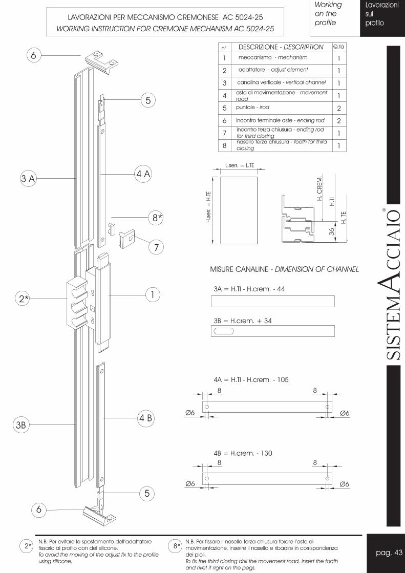
DESCRIZIONE - DESCRIPTION
meccanismo - mechanism
adattatore - adjust element
canalina verticale - vertical channel
asta di movimentazione - movement
road
incontro terminale aste - ending rod
incontro terza chiusura - ending rod
for third closing
puntale - irod
nasello terza chiusura - tooth for third
closing
L.serr. = L.TE
H.s
err.
=H
.TE
H.T
IH.C
REM
.
H.TE
3A = H.TI - H.crem. - 44
3B = H.crem. + 34
MISURE CANALINE - DIMENSION OF CHANNEL
4A = H.TI - H.crem. - 105
4B = H.crem. - 130
N.B. Per evitare lo spostamento dell’adattatore
fissarlo al profilo con del silicone.
To avoid the moving of the adjust fix to the profile
using silicone.
N.B. Per fissare il nasello terza chiusura forare l’asta di
movimentazione, inserire il nasello e ribadire in corrispondenza
dei pioli.
To fix the third closing drill the movement road, insert the tooth
and rivet it right on the pegs.
pag. 43
Lavorazioni
sul
profilo
Working
on the
profileLAVORAZIONI PER MECCANISMO CREMONESE AC 5024-25
WORKING INSTRUCTION FOR CREMONE MECHANISM AC 5024-25
���
��
�������
��
�

MISURE PER IL FISSAGGIO DELLE CERNIERE ANTARIBALTA
DIMENSION FOR FIXING HINGES OF TILT AND TURNER
Abbassare (tramite fresatura o pantografo)
l’aggraffatura di 2 mm. In corrispondenza
della feritoia per permettere il prefetto
inserimento del meccanismo cremonese.
Lower (by pantograf) the seaming of 2
mm. In correspondence af hole in order to
introduce the cremone mechanism
perfectly.
N.B. In caso di profilo maggiorato la
lavorazione non va eseguita.
Not to be done in case of max. section.
pag. 44
Lavorazioni
sul
profilo
Working
on the
profileLAVORAZIONI PER MECCANISMO ANTA RIBALTA AC 5027-28
WORKING INSTRUCTION FOR TILT AND TURN MECHANISM AC 5027-28
���
��
�������
��
�
Lavorazione effettuabile con AT 2024
Working with AT 2024
N.B. Rifilatura del quadretto maniglia a 35 mm.
Milling of the square of the handle 35 mm.
Fori per maniglia cremonese AC5056
Hole for handle AC5056
H Cremonese
Cremone
Rif.
Mis
ura
Hc
rem
.C
rem
one
Rif.
Rif.
mis
ura
fori
TI-
Rif.
ma
keho
les
TI
Rif.
mis
ura
fori
TE-
Rif.
ma
keho
les
TE
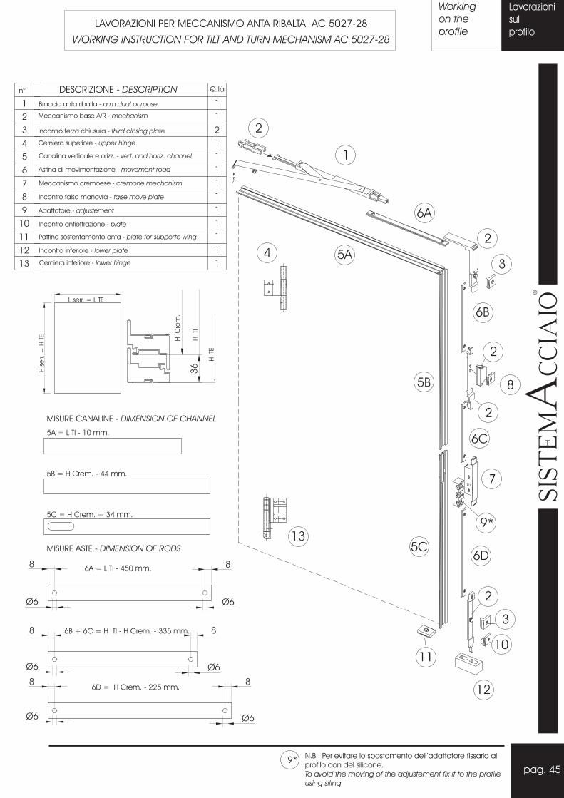
DESCRIZIONE - DESCRIPTION
Braccio anta ribalta - arm dual purpose
Meccanismo base A/R - mechanism
Incontro terza chiusura - third closing plate
Cerniera superiore - upper hinge
Canalina verticale e orizz. - vert. and horiz. channel
Astina di movimentazione - movement road
Meccanismo cremoese - cremone mechanism
Incontro falsa manovra - false move plate
Adattatore - adjustement
Incontro antieffrazione - plate
Pattino sostentamento anta - plate for supporto wing
Incontro inferiore - lower plate
Cerniera inferiore - lower hinge
L serr. = L TE
Hse
rr.=
HTE H
Cre
m.
HTI
HTE
5A = L TI - 10 mm.
5B = H Crem. - 44 mm.
MISURE CANALINE - DIMENSION OF CHANNEL
5C = H Crem. + 34 mm.
MISURE ASTE - DIMENSION OF RODS
6A = L TI - 450 mm.
6B + 6C = H TI - H Crem. - 335 mm.
6D = H Crem. - 225 mm.
N.B.: Per evitare lo spostamento dell’adattatore fissarlo al
profilo con del silicone.
To avold the moving of the adjustement fix it to the profile
using siling.
pag. 45
Lavorazioni
sul
profilo
Working
on the
profileLAVORAZIONI PER MECCANISMO ANTA RIBALTA AC 5027-28
WORKING INSTRUCTION FOR TILT AND TURN MECHANISM AC 5027-28
���
��
�������
��
�

pag
DESCRIZIONE - DESCRIPTION
Braccio anta ribalta ridotto - arm dual purpose rid.
Meccanismo base A/R - mechanism
Incontro terza chiusura - third closing plate
Cerniera superiore - upper hinge
Canalina verticale e orizz. - vert. and horiz. channel
Astina di movimentazione - movement road
Meccanismo cremoese - cremone mechanism
Incontro falsa manovra - false move plate
Adattatore - adjustement
Incontro antieffrazione - plate
Pattino sostentamento anta - plate for supporto wing
Incontro inferiore - lower plate
Cerniera inferiore - lower hinge
L serr. = L TE
Hse
rr.=
HTE H
Cre
m.
HTI
HTE
5A = L TI - 10 mm.
5B = H Crem. - 44 mm.
MISURE CANALINE - DIMENSION OF CHANNEL
5C = H Crem. + 34 mm.
MISURE ASTE - DIMENSION OF RODS
6A = L TI - 310 mm.
6B + 6C = H TI - H Crem. - 335 mm.
6D = H Crem. - 225 mm.
N.B.: Per evitare lo spostamento dell’adattatore fissarlo al
profilo con del silicone.
To avold the moving of the adjustement fix it to the profile
using siling.
pag. 46
Lavorazioni
sul
profilo
Working
on the
profileLAVORAZIONI PER MECCANISMO RIDOTTO ANTA RIBALTA AC 5027X-28X
WORKING INSTRUCTION FOR TILT AND TURN MECHANISM AC 5027X-28X
���
��
�������
��
�

MISURE CANALINE - DIMENSION OF CHANNEL
pag. 47
Lavorazioni
sul
profilo
Working
on the
profileKIT AGGIUNTIVI PER ANTA RIBALTA AC 5041 E AC 5043
ADDITIONAL KIT FOR TILT AND TURN MECHANISM AC 5041 AND AC 5043
Descrizione - Descriptionpos. q.tà
Canalina per asta movimento - Channel for movement road5 1
6
14
1
1
Incontro per 3° chiusura - Third closing plate
Rinvio d’angolo - Corner fitting
Braccio aggiuntivo anta ribalta - Additional arm dual purpose15 1
Descrizione - Descriptionpos. q.tà
AC 5043
BRACCIO SUPPLEMENTARE ANTA RIBALTA
ADDITIONAL ARM DUAL PURPOSE
AC 5041
KIT CHIUSURA SUPPLEMENTARE ANTA RIBALTA
TILT AND TURN ADDITIONAL KIT LOCKINGPer altezza anta > 1200 mm
For leaf height > 1200 mm
Per larghezza anta > 1200 mm
For leaf lenght > 1200 mm
���
��
�������
��
�

pag
Rondella di spessoramento
Thichness
pag. 48
Lavorazioni
sul
profilo
Working
on the
profileLAVORAZIONI PER KIT CHIUSURA SECONDA ANTA AC 5042
WORKING INSTRUCTION FOR SECOND LEAF LOCK KIT AC 5042
Abbassare (tramite fresatura o pantografo)
l’aggraffatura di 2 mm. In corrispondenza
della feritoia per permettere il prefetto
inserimento del meccanismo cremonese.
Lower (by pantograf) the seaming of 2
mm. In correspondence af hole in order to
introduce the cremone mechanism
perfectly.
pos.
Canalina per asta movimento - Channel for movement road1 1
2 1Incontro per 3° chiusura - Third closing plate
3 1Rinvio d’angolo - Corner fitting
Canalina per asta movimento - Channel for movement road4 1
5 1Incontro per 3° chiusura - Third closing plate
6 1Rinvio d’angolo - Corner fitting���
��
�������
��
�
1 2
3
4
6
6

Fori eseguibili con
maschera AT2002
Hole to be done
using jig AT2002
Inserto filettatoThereaded insert
* - La lavorazione può essere prevista anche in
posizioni intermedie della porta.
- La lavorazione SX speculare alla DX.
- Lavorazione valida anche per aperture esterne.
* - Working can be forseen in the middle posistions
of the door.
- Working on left and right side are specular.
- Working can be done also on external opening.
pag. 49
Lavorazioni
sul
profilo
Working
on the
profileSISTEMA DI FISSAGGIO CERNIERA AC 5029
INSTRUCTION FOR FIXING HINGE AC 5029
SISTEMA DI FISSAGGIO CERNIERA AC 6045
INSTRUCTION FOR FIXING HINGE AC 6045
Limiti dimensionali /
Peso anta / : 50 kg
Larghezza anta / : 1 m
Dimensional limits:
Leaf weight
Leaf lenght
Limiti dimensionali /
Peso anta / : 70 kg
Dimensional limits:
Leaf weight
SISTEMA DI FISSAGGIO CERNIERA AC 6006
INSTRUCTION FOR FIXING HINGE AC 6006
Limiti dimensionali /
Peso anta / : 100 kg
Dimensional limits:
Leaf weight
Fori eseguibili con
maschera AT2002
Hole to be done
using jig AT2002
Inserto filettatoThereaded insert
���
��
�������
��
�
Rif.
mis
ura
fori
TE-
Rif.
ma
keho
les
TE
Rif.
mis
ura
fori
TI-
Rif.
ma
keho
les
TI
Rif.
mis
ura
-R
if.m
ake
Rif.
mis
ura
-R
if.m
ake

Self tapping screws TC 4,2 x 9,5
Viti autofilettanti TC 4,2 x 9,5
N.B. - n° 2 cerniere AC5029 in posizione orizzontale.
- n° 2 hinges AC5029 in horizontal position.
Viti autofilettanti TC 4,8 x 16 (CV1782)Self tapping screws TC 4,8 x 16 (CV1782)
Viti autof. TC 3,9 x 12,7
Self tapping screw TC 3,9 x 12,7
pag. 50
Lavorazioni
sul
profilo
Working
on the
profileLAVORAZIONI PER FISSAGGIO LIMITATORI VASISTAS AC 5030
INSTRUCTION FOR FIXING CASEMENT STAY AC 5030
LAVORAZIONI PER CRICCHETTO VASISTAS AC 5040
WORKING INSTRUCTION FOR CATCH DETENT AC 5040
Limiti dimensionali /
Peso anta / : 50 kg
Altezza anta / : min 320 mm
Dimensional limits:
Leaf weight
Leaf height
���
��
�������
��
�

DESCRIZIONE - DESCRIPTION
Compassi - Side arms.
Spessori per compassi su TI.
Shins for side arms on internal frame.
Spessore di compensazione
fissato sul T.I. con le viti dei
compassi.
Adjustement spacer applied
on internal frame with screws
for side arms.
Regolazione frizione a seconda del peso
dell’anta.
Adjustement of clutch according to the
weight of wing.
Limitatore.
Limiting devicer.
- Fissare i compassi in corrispondenza dei fori
asolati ( foratura su profili per viti TC 4,8X13).
- Verificare il funzionamento dei compassi.
- Fissare l’apertura massima desiderata mediante
il limitatore di apertura.
- Completare l’operazione di fissaggio nei rimanenti
fori.
- Fix the side arms in accordance to the hles
(holes on sections .
- Test the running of side arms.
- Complete the operation by fixing the remaining
holes.
TC 4,8X13)
Ø 4
Ø 4 for screws
Maschera regolabile per fissaggio maniglia.
Adjustable jig for fixing handle.
Eseguire fori per viti TC 4,8 X 19,5.
Execute holes for self tapping
screws TC 4,8 X 19,5.
Ø 4
Ø 4
Distanziatori - Spacer
Execute holes for self tapping
screws TPS 3,5 X 19,5.
Ø 4
Eseguire fori
viti TPS autof. 3;5 x 19;5
Ø 4 passanti per
pag. 51
Lavorazioni
sul
profilo
Working
on the
profileSISTEMA DI FISSAGGIO COMPASSI AC 5039
INSTRUCTION FOR FIXING SIDE ARMS AC 5039
Limiti dimensionali /
Peso anta / : 75 kg
Altezza anta / : min 800 mm
Dimensional limits:
Leaf weight
Leaf height
SISTEMA DI FISSAGGIO MANIGLIA E INCONTRO AC 5037
INSTRUCTION FOR FIXING HANDLE AND PLATE AC 5037
���
��
�������
��
�
1
2
4
3
24
2525
24
6
7
8
8
8
8
20
910 11
12
2323 2323
13
17
18 19
1615
14
21
13
7
26 26
28
28
28
28
27
2727
27
22
7
5
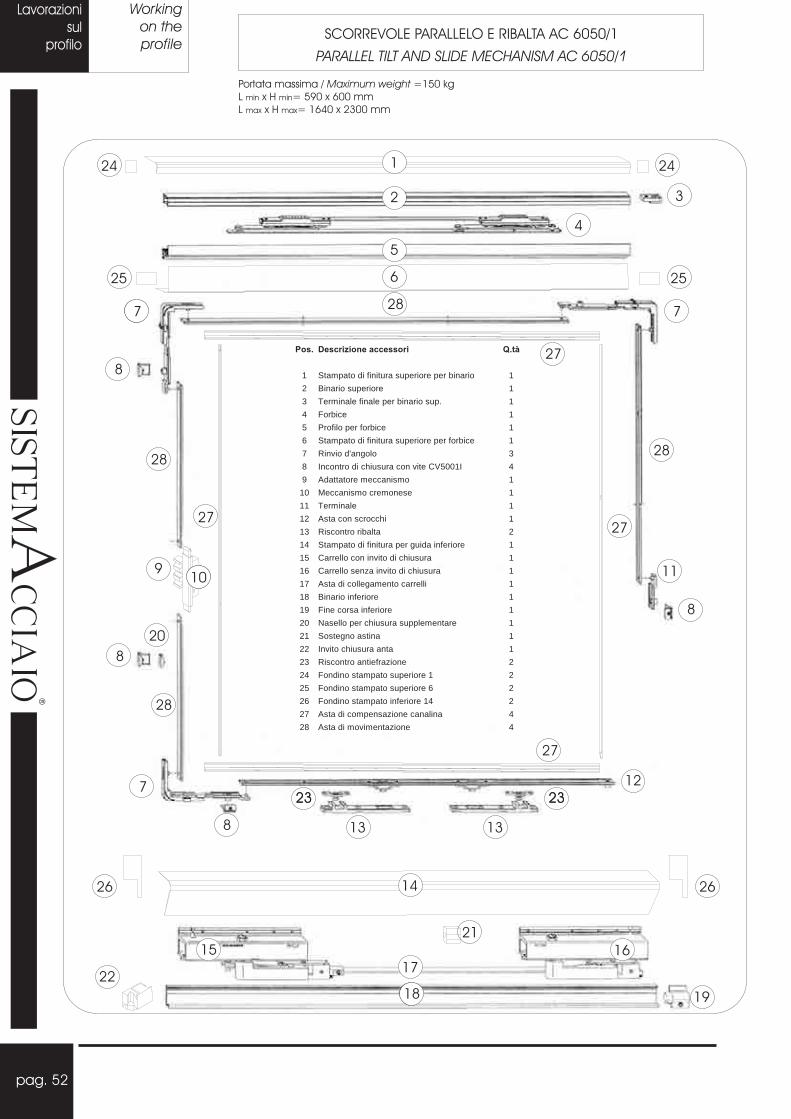
Pos. Descrizione accessori Q.tà
1 Stampato di finitura superiore per binario 1
2 Binario superiore 1
3 Terminale finale per binario sup. 1
4 Forbice 1
5 Profilo per forbice 1
6 Stampato di finitura superiore per forbice 1
7 Rinvio d'angolo 3
8 Incontro di chiusura con vite CV5001I 4
9 Adattatore meccanismo 1
10 Meccanismo cremonese 1
11 Terminale 1
12 Asta con scrocchi 1
13 Riscontro ribalta 2
14 Stampato di finitura per guida inferiore 1
15 Carrello con invito di chiusura 1
16 Carrello senza invito di chiusura 1
17 Asta di collegamento carrelli 1
18 Binario inferiore 1
19 Fine corsa inferiore 1
20 Nasello per chiusura supplementare 1
21 Sostegno astina 1
22 Invito chiusura anta 1
23 Riscontro antiefrazione 2
24 Fondino stampato superiore 1 2
25 Fondino stampato superiore 6 2
26 Fondino stampato inferiore 14 2
27 Asta di compensazione canalina 4
28 Asta di movimentazione 4
pag. 52
Lavorazioni
sul
profilo
Working
on the
profileSCORREVOLE PARALLELO E RIBALTA AC 6050/1
PARALLEL TILT AND SLIDE MECHANISM AC 6050/1
Portata massima / 150 kg
L x H = 590 x 600 mm
Maximum weight =
min min
L x H = 1640 x 2300 mmmax max
���
��
�������
��
�

Nodo superioreUpper section
Regolazione verticale 3 mm.
Vertical adjustment 3 mm.
±
±
Fissare la forbice (4) al profilo
(5) tenendo il filo esterno (vedi
pag. seguenti)
Fixing fitting (4) to the profile
(5) starting from external side
(see also next pages)
pag. 53
Lavorazioni
sul
profilo
Working
on the
profileSCORREVOLE PARALLELO E RIBALTA AC 6050/1
PARALLEL TILT AND SLIDE MECHANISM AC 6050/1
Nodo inferioreLower section
Distinte di taglioCutting list
���
��
�������
��
�

Saldare il fondino al profilo e
poi fissarlo al meccnismo
Welding the cap to the
profile and then fixing to the
mechanism
Fissare le guide con viti TPS 4,2 x 17 come indicato nel disegno.
Fixing the slides with screws TPS 4,2 x 17 as specified on the drowing.
pag. 54
Lavorazioni
sul
profilo
Working
on the
profileSCORREVOLE PARALLELO E RIBALTA AC 6050/1
PARALLEL TILT AND SLIDE MECHANISM AC 6050/1
Nodo superioreUpper section
Saldare il fondino al profilo e
poi fissarlo alla guida.
Welding the cap to the
profile and then fixing to the
slide.
Nodo inferioreLower section
���
��
�������
��
�

Fissare il particolare 8 al TE, poi in
corrispondenza fissare il particolare
20 nell’astina di movimentazione e
ribadire.
Fixing fitting 8 to the frame, then
fixing fitting 20 into connecting rod
and riveting
Fori 3,2 / Holes 3,2Ø Ø
pag. 55
Lavorazioni
sul
profilo
Working
on the
profileSCORREVOLE PARALLELO E RIBALTA AC 6050/1
PARALLEL TILT AND SLIDE MECHANISM AC 6050/1
���
��
�������
��
�
Misure per fissaggio accessori al telaio esterno
Measure for fixing the fittings to frame

N.B. - spessore da fissare al profilo per
evitarne la caduta
pag. 56
Lavorazioni
sul
profilo
Working
on the
profileSCORREVOLE PARALLELO E RIBALTA AC 6050/1
PARALLEL TILT AND SLIDE MECHANISM AC 6050/1
Misure per fissaggio accessori al telaio interno
Measure for fixing the fittings to internal frame
Misure per fissaggio cremonese
Measure for fixing cremon mechanism
N.B. - hicness to fix to the profile to
avoid the fall
t
Fori 3,2 / Holes 3,2Ø Ø���
��
�������
��
�
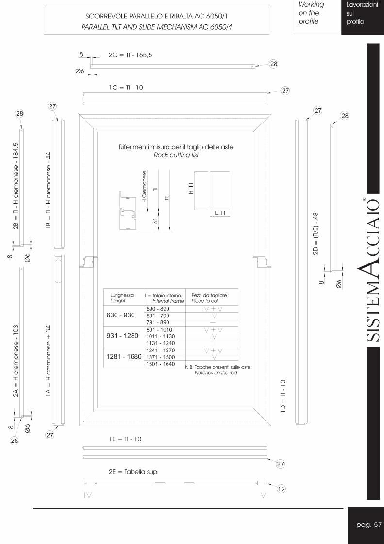
2C = TI - 165,5
1C = TI - 10
1E = TI - 10
2E = Tabella sup.
2A
=H
cre
mo
ne
se-
10
3
1A
=H
cre
mo
ne
se+
34
2B
=TI
-H
cre
mo
ne
se-
18
4,5
1B
=TI
-H
cre
mo
ne
se-
44
2D
=(T
I/2
)-
48
1D
=TI
-1
0
Lunghezza
LenghtTI= telaio interno
Internal frame
Pezzi da tagliare
Piece to cut
N.B. Tacche presenti sulle aste
Notches on the rod
pag. 57
Lavorazioni
sul
profilo
Working
on the
profileSCORREVOLE PARALLELO E RIBALTA AC 6050/1
PARALLEL TILT AND SLIDE MECHANISM AC 6050/1
Riferimenti misura per il taglio delle aste
Rods cutting list
���
��
�������
��
�

A) Finecorsa inferiore regolabile
con chiave a brugola.
Adjustment of inferior stop with socket
wrench
C) Invito per chiusura anta, regolabile
con chiave a brugola.
Adjustment of closing mechanism with
socket wrench
D) Regolazione verticale
( 3 mm) con
chiave a brugola.
Vertical adjustment
( 3 mm) with
socket wrench
±
±
1) Inserire la forbice 4 nel binario ingrassato 2.
N.B. Per apertura DX aprire la forbice con la vite di fissaggio
rivolta a sinistra;
Per apertura SX aprire la forbice con la vite di fissaggio
rivolta a destra.
2) Posizionare l’anta tenendola inclinata sul binario 18 e
inserire la forbice 4 nel profilo forbice 5.
3) Fissare la vite della forbice all’estremità del profilo forbice.
pag. 58
Lavorazioni
sul
profilo
Working
on the
profileSCORREVOLE PARALLELO E RIBALTA AC 6050/1
PARALLEL TILT AND SLIDE MECHANISM AC 6050/1
INSERIMENTO DELL’ANTA
LEAF FIXING
���
��
�������
��
�
B) Finecorsa superiore regolabile
con chiave a brugola.
Adjustment of superior stop with socket
wrench
1) Insert the stay arm 4 in greassed rail 2.
N.B. For right hand-side opening, open the stay arm with
the fixing screw facing left;
For left hand-side opening, open the stay arm with
the fixing screw facing right;
2) Tilt the leaf to insert in the rail 18 and position the stay arm
into its profile.
3) Fix stay arm screw at the end of its profile

Cerniera AC 6056
Hinge AC 6056
Contropiastra di fissaggio
Fixing plate
Telaio esterno
External frame
Spacco inserimento cerniera
Hole for insert the hinge
Fori e asole di fissaggio e regolazione
Fixing and adjustment holes
Fori fissaggio contropiastra
Hole for plate fixing
pag. 59
Lavorazioni
sul
profilo
Working
on the
profileSISTEMA DI FISSAGGIO CERNIERA A SCOMPARSA AC 6056
INSTRUCTION FOR FIXING CONCEALED HINGES AC 6056
Telaio interno
Internal frame
Portata massima / 160 kg
Apertura massima / = 96°
Maximum weight =
Maximum opening
���
��
�������
��
�

1: Pattini
2: Spazzolino
3: Carrello anteriore
4: Carrello posteriore
5:
6: Incontro chiusura inferiore
7: Boccole
8: Perno di arressto 6x16
9: Vite testa piatta M5x13
10: Cappuccio di chiusura
11: Arresto
12: Barra di unione
13: Meccanismo
14: Distanziatori per cremonese
Incontro chiusura superiore
1 12
5a
5a
9 138 8
12
4
7
10
11
11
14
SU RICHIESTA
pag. 60
Lavorazioni
sul
profilo
Working
on the
profileALZANTE SCORREVOLE PARALLELO AC 6148
LIFT AND SLIDE MECHANISM AC 6148
Portata massima / 250 kg
L x H = 720 x 1175 mm
Maximum weight =
min min
L x H = 3350 x 2675 mmmax max
���
��
�������
��
�

Rivetti 4.
Rivets 4.
Ø
Ø
Profili zoccolo
Socle section
P.3141
Fissare la plastica A al profilo B con viti TPS
4.2 x 32 ogni 300 mm e siliconare.
Fixing plastic section A to section B with
screws TPS 4.2 x 32 every 300 mm and
then apply silicone
pag. 61
Lavorazioni
sul
profilo
Working
on the
profileALZANTE SCORREVOLE PARALLELO AC 6148
LIFT AND SLIDE MECHANISM AC 6148
SCHEMA ASSIEMAGGIO PROFILIASSEMBLING PROFILE DIAGRAM
Rivetti 4.
Rivets 4.
Ø
Ø
TELAIO ESTERNO / P.3143 e P.3144EXTERNAL FRAMERealizzare separatamente i telai A, B e C e poi unirli tramite rivetti o saldatura
Produce one a time frame A,B and C: then joining them by rivets or welding
A B C
A B C
PROFILI ANTA / LEAF SECTIONS
P.3140
P.3101 P.3148
P.3102
P.3147
P.3102
P.3147
Profili superiori
Upper section
Profili laterali
Lateral section
GIUNTO CENTRALE / CENTRAL JOINTRealizzare separatamente il profilo P.3141 e poi unirlo all’anta con viti TCTC 4.8 x 22
Produce one a time section P.3141 and then joining it to leaf section with screws
P.3102
P.3103
P.3141 P.3141
GU 0002
GU 0002
A
B
���
��
�������
��
�

Astina di collegamento dei carrelli
Connecting rod for trolley
pag. 62
Lavorazioni
sul
profilo
Working
on the
profileALZANTE SCORREVOLE PARALLELO AC 6148
LIFT AND SLIDE MECHANISM AC 6148
Larghezza anta / Leaf lenght
Larghezza anta - 620
Leaf lenght - 620
Porta
/=
97
8D
oo
r
Fine
stra
/=
37
8W
ind
ow
���
��
�������
��
�

pag. 63
Lavorazioni
sul
profilo
Working
on the
profileLAVORAZIONE PER INSERIMENTO FONDINO DI TESTA AC 6119
WORKING FOR TERMINAL CUP AC 6119
���
��
�������
��
�
SOLUZIONE ANGOLO 90° E ANGOLO VARIABILE
SOLUTION CORNER 90° AND VARIABLE CORNER
Fresare il profilo
Working the section
Rife
rime
nto
mis
ura
ca
me
rap
rofil
o
Me
asu
rere
fere
nc
efro
mle
afse
ctio
n
AC 6119
Fissare il profilo con resina siliconica
Fix the profile with silicone
P 2021
Vite / TCTC 5,5 x 13Screw
P 2020
AC 6049
pag. 64
���
��
�������
��
�
26
202
0
Lavorazionisul
profilo
Workingon theprofile
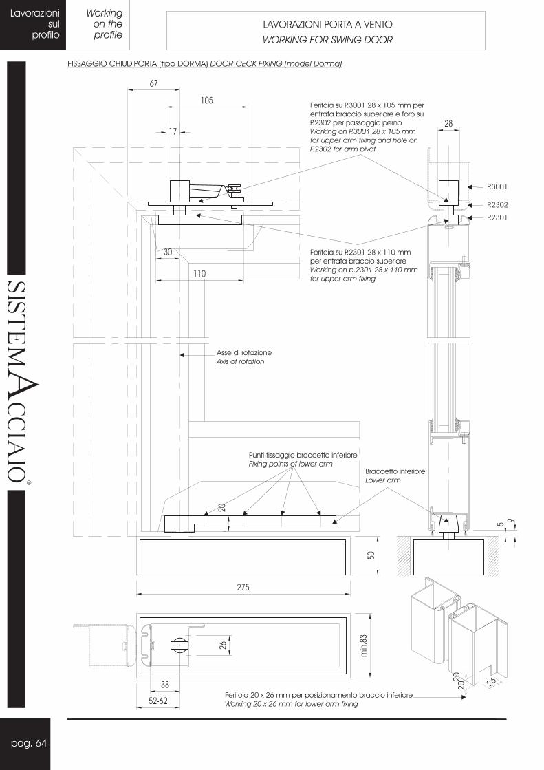
LAVORAZIONI PORTA A VENTO
WORKING FOR SWING DOOR
FISSAGGIO CHIUDIPORTA (tipo DORMA) DOOR CECK FIXING (model Dorma)
Asse di rotazione
Axis of rotation
Punti fissaggio braccetto inferiore
Fixing points of lower armBraccetto inferiore
Lower arm
Feritoia su P.2301 28 x 110 mm
per entrata braccio superiore
Working on p.2301 28 x 110 mm
for upper arm fixing
P.2301
Feritoia su P.3001 28 x 105 mm per
entrata braccio superiore e foro su
P.2302 per passaggio perno
Working on P.3001 28 x 105 mm
for upper arm fixing and hole on
P.2302 for arm pivot
P.3001
P.2302
Feritoia 20 x 26 mm per posizionamento braccio inferiore
Working 20 x 26 mm for lower arm fixing

LAVORAZIONI PORTA A VENTO
WORKING FOR SWING DOOR
Workingon theprofile
Lavorazionisulprofilo
pag. 65
���
��
�������
��
�
Viti CV 5001i con boccole CV 5012i
Screws CV 5001i with bushings CV 5012i
300 - 400 mm
FISSAGGIO PROFILI DI RIPORTO / FINISHING SECTION FIXING (P.2301 - P.2302)
AC 6049i: n° 4 - 5
FISSAGGIO SERRATURA / (CISA art.46212)LOCK FIXING
entrata con P.3001: 35 mm
entrata con P.3101: 25 mm
backset con P.3001: 35 mm
backset con P.3101: 25 mm
FISSAGGIO CATENACCIO / (SAVIO art.1565)DOOR LATCH FIXING
Foro per entrata
puntale (su P.2301 e P.2302)
Hole
Ø 8.5
Ø 8.5 for teminals (on
P.2301 and P.2302)
P.2302
P.2301
Foro per entrata
puntale (su P.2301 e P.2302)
Hole
Ø 8.5
Ø 8.5 for teminals (on
P.2301 and P.2302)
Utilizzare il catenaccio
come maschera per il
fissaggio
Use the latch as jig for its
fixing
Feritoia per la movimentazione
Working for latch handling
Foro per puntale inferiore
Hole for lower terminal
P.3001
P.3101P.3101
P.3001
P.2302 P.2301
Lavorazionisulprofilo
pag. 65

pag. 66
Portone
industriale
a libro
Folding
industrial
doorPORTONE INDUSTRIALE A LIBRO
FOLDING INDUSTRIAL DOOR
*Il portone viene aperto impacchettandosi su due lati;
per l’assemblaggio offre la soluzione SALDATA.
For assembly please refert to the welded solution.
���
��
�������
��
�

pag. 67
Portone
industriale
a libro
Folding
industrial
door
4 ANTE CON IMPACCO
OLTRE LUCE
4 PANELS WITH BI-FOLD
INCLUDING LITES
���
��
�������
��
�
Lenght
Lungh.
n°
n°
96
6
1
1
1
3
2
3
1
7
2
4
2
1
ACCESSORI / FITTINGS
Description
Descrizione
AC 0729
AC 0732
AC 0905
AC 1229
AC 1249
AC 1259
AC 3470
AC 5014
AC 5015
AC 5019
AC 5020
AC 5023
AC 8764
AC 1251
Lenght
Lungh.
H-1260
L+1060
(L-40)/4
GUIDE E ASTE / GUIDES AND RODS
1130
L+580
L+580
H-40
L-10
H-35
n°
n°
6
4
1
1
1
1
1
1
2
Guida rullino deviatore
PZ 0021
Roll deviator guide
GUARNIZIONI / GASKETS
Asta cariglione
PZ 0016
Lever handle rod
Guarnizione ante
GE 0010
Leaf gasket
Guida superiore
PZ 1030
Superior guide
Spazzolino ante
GU 0142
Leaf brushing
Spazzolino telaio
GU 0142
Frame brushing
Description
Descrizione
Guida inferiore
PZ 0034
Inferior guide
Lenght
FERMAPANNELLO / P.2015STOP PANEL
Lungh.
(L-160)/4
H1-100
L1-140
H-35
L-10
H-40
TELAIO ESTERNO / P.0014FRAME
ANTA / P.0014INTERNAL FRAME
n°
n°
2
1
8
8
8
8
L x H = (H1-112) x (L1-112)
PANNELLO / PANEL
Traverso superiore
Upper transom
Description
Descrizione
Fianchi
Side parts
Fianchi
Side parts
Fianchi
Side parts
Traversi
Transoms
Traversi
Transoms

La presente documentazione è stata redatta a cura della Secco Sistemi S.p.A. E’ di sua proprietà e ne è vietata la
riproduzione anche parziale senza preventiva autorizzazione.
Il materiale può essere utilizzato unicamente dai clienti per l’elaborazione dei prodotti indicati. La società declina ogni
responsabilità per produzioni effettuate fuori dalle proprie indicazioni senza seguire le regole dell’arte. Si riserva il diritto
di apportare ai propri prodotti quelle modifiche che riterrà utili e necessarie, senza vincolo di informazione preventiva.
Deve essere cura del serramentista Secco Sistemi accertarsi che le note tecniche in suo possesso siano l’ultima
edizione e comunque rispondenti al prodotto da realizzare.
This document has been compiled by the Secco Sistemi S.p.A.; this documentation belongs to them and it is
forbidden it’s reproduction, also a partial one, without previous authorization. The material can be used only by the
customers of the indicated products. Society declines all responsability for productions effected out of it’s directions
without following the rules of the art. It reserves the right to itself to make in it’s products those changes which it will
think useful and necessary without ties of previous information. The Secco window fabbricator must take care to
make sure that the technical notes in his possession are the last edition and in any case relative to the product to
manufacture.
Note:
INDICE / INDEX
Profilati / Sections pag. 1
Accessori / Hardware pag. 13
Guarnizioni / Gasket pag. 18
Attrezzature / Equipment pag. 19
Sezioni porte / Door drawings pag. 20
Sezioni finestre / Windows drawings pag. 24
Sezioni varie / Various drawings pag. 26
Distinte di taglio / Cutting list pag. 32
Lavorazioni / Workings
� Bilico / Pivot pag. 36
� Scarico acqua / Water drip pag. 38
� Giunto centrale 2 ante / Double leaf central joint pag. 39
� Serrature / Locks pag. 40
� Cremonese / Side-hung sash pag. 42
� Anta ribalta / Tilt and turn sash pag. 44
� Chiusura seconda anta / Second leaf lock pag. 48
� Cerniere / Hinges AC 5029 – AC6006 – AC 6045 pag. 49
� Vasistas e sporgere / Bottom hung and outside sash pag. 50
� Scorrevole parallelo e ribalta / Tilt and slide windows pag. 52
� Cerniera a scomparsa / Concealed hinge AC 6056i pag. 59
� Alzante scorrevole / Lift-slide door pag. 60
� Profili complementari / Other profile pag. 63
� Porta a vento / Swing door pag. 64
� Portoni industriali / Industrial door pag. 66
Specifiche materiale / Material specification pag. 68
AIn ACCIAIO DECAPATO - ZINCATO 15/10

Structural shapes of 55 mm.section, 15/10 mm.
thick, made after cold-roll forming of
l - band “Sendzemir System”
assemled by mechanical clamping of hight
resistence, with standards according to UNI EN
10142/3/7, with zinc coating of 200 gr/sq.mt.,
on both faces or
. Thickness of 15/10 mm. and
profile shaping, guarantee an excellent strenght
of the product and the best safety against
b r e a k i n g .
of inside and outside sections
g ive h igh e legance to the produc t .
inside-outside seal in the
coup l ing o f in -and ou t s ide f rames .
allowing a great
reduct ion of working times.
galvanized stee
type “pickled steel”.
STRENGHT
FLAT DESIGN
DOUBLE GASKET
PIPE FOR ACCESSORIES
STRUCTURAL SHAPES OUT/INSIDE
pikled
s t e e
COMPLETE SUPPLY OF ACCESSORIES TO
BE APPLIED MECHANICALLY IN THE
SUITABLE EUROPEAN ROOM-PIPE.
with
thick zinc coating of 200 gr./sq. mt. or
Screwed-hinges for windows
Screwed-hinges for doors
Concealed hinges
Welded hinges for doors
Outside-opening compasses
Opening controllers wasistas
Kit for side-hung sash
Kit for tilt-turn sash
Kit for parallel tilt-slide sash
Kit for left-slide sash
Kit for pivot-opening
Any other tool for movement and closing
EUROPEAN ROOM
ARCH-BENDING,
QUALITY OF PRODUCT,
DELIVERY SERVICE,
f o r load ing o f
a c c e s s o r i e s .
accord ing to the
customer’s demands.
guaranted by
conformity to UNI EN 10142/3/7 standards.
guaranted by the area
dealer with immediate availabil i ty .
For workings of no
investment for specific equipment is required. A
simple mask is sufficient to make quickly and
precisly the holes for inserting the various types
of glass beading.
l .
Profilati con sezione 55 mm, spessore 15/10 mm,realizzati da profilatura a freddo di nastro
Sistema Sendzimir , chiusi medianteunione meccanica ad alta resistenza, concaratteristiche non inferiori alla norma UNI EN10142/3/7 e con rivestimento di zinco pari a 200gr./mq., Su entrambe le facce o
. Lo spessore da 15/10 mm e laconformazione del profilo, garantiscono unaelevata robustezza del prodotto finito e lamassima sicurezza antiscasso.
con elevato rivestimento di zinco pari a 200gr./mq. o in
delle ante inerna ed esterna,conferiscono elevata eleganza al prodotto finito.
internaed esterna nell’accoppiamento telaio interno -telaio esterno.
checonsente una notevole riduzione dei tempi dilavorazione.
acciaiozincato
in versione acciaiodecapato
ROBUSTEZZA
PROFILATI ZINCATI ESTERNO/INTERNO
acciaio decapato.
COMPLANARITA’
DOPPIA GUARNIZIONE DI TENUTA
CANALINA PORTA ACCESSORI
� �
� �CAMERA EUROPEA
CURVATURA AD ARCO
QUALITÀ DEL PRODOTTO
SERVIZIO CONSEGNE
per l’alloggiamentodegli accessori.
in conformita’ alleesigenze del cliente.
garantita dallaconformità delle norme UNI EN 10142/3/7.
garant i to dalcommerciante di zona con disponibilitài m m e d i a t a .
Per le lavorazioni delnon è richiesto nessun investimento inattrezzature specifiche. È sufficiente unasemplice maschera per realizzare con precisione erapidità i fori per l’applicazione dei vari tipi difermavetro.
Cerniere da avvitare per finestreCerniere da avvitare per porteCerniere a scomparsa per porteCerniere a saldare per porteCompassi per aperture a sporgereLimitatori di apertura wasistasKit cremonese per apertura ad antaKit per apertura adKit scorrevole parallelo e ribaltaKit alzante scorrevoleKit per apertura a bilicoOgni altro componente per la movimentazione
antaribalta
COMPLETA DOTAZIONE DI ACCESSORIDA APPLICARSI MECCANICAMENTENELL’APPOSITA CANALINA A CAMERAE U R O P E A
A
Feb
bra
io2
00
6
In ACCIAIO DECAPATO - ZINCATO 15/10
SECCO SISTEMI S.p.A. - VIA TERRAGLIO, 195 - 31022 PREGANZIOL (TV) - TEL. ++39 0422 497700 - FAX ++39 0422 497705e-mail: [email protected] - web: www.seccosistemi.it