Coordination Chemistry III 2nd
34
Coordination Chemistry III: Electronic Spectra Chapter 11
Transcript of Coordination Chemistry III 2nd
Coordination Chemistry III: Electronic Spectra
Chapter 11
Coordination Complexes
• Unlike most organic compounds, many coordination compounds have vivid colors.– These vivid colors are due to the electronic
transitions between the d-orbitals of the metal.
• The energy levels of d electron configurations, however, are usually more complicated than might be expected since the electrons in the atomic orbitals interact with each other.
Absorption of Light
• Complementary colors – if a compound absorbed light of one color, the complement of that color is observed.– [Cu(H2O)6]2+ has a blue color. What is absorbed?
• Beer-Lambert Absorption Law• log(Io/I)=A=lc (define variables)
• In a common absorption spectrum, the A is plotted versus wavelength or cm-1 (1/).
Quantum Numbers of Multielectron Atoms
• In order to understand energy transitions between states with more than one electron, we need to understand in more detail how these electrons interact with each other.
• Each conceivable set of individual ml and ms values constitutes a microstate of the configuration.– How many microstates in a d1 configuration?– Examine the carbon atom (p2 configuration)
• Determine the electron configuration and quantum numbers.• Independently, each of the 2p electrons could have one of six possible
combinations. The two electrons, however, are not independent of each other.
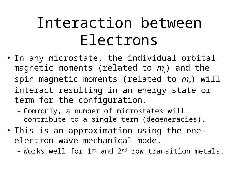
Interaction between Electrons
• In any microstate, the individual orbital magnetic moments (related to ml) and the spin magnetic moments (related to ms) will interact resulting in an energy state or term for the configuration.– Commonly, a number of microstates will contribute to a single
term (degeneracies).
• This is an approximation using the one-electron wave mechanical mode.– Works well for 1st and 2nd row transition metals.
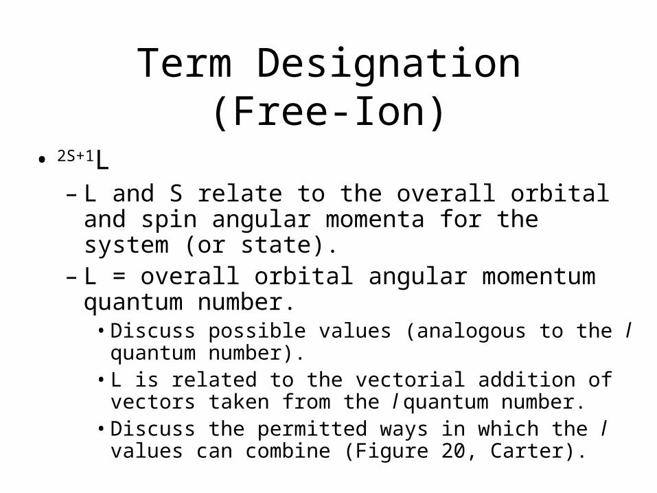
Term Designation (Free-Ion)
• 2S+1L– L and S relate to the overall orbital and spin angular
momenta for the system (or state).– L = overall orbital angular momentum quantum
number.• Discuss possible values (analogous to the l quantum
number).• L is related to the vectorial addition of vectors taken from
the l quantum number.• Discuss the permitted ways in which the l values can
combine (Figure 20, Carter).
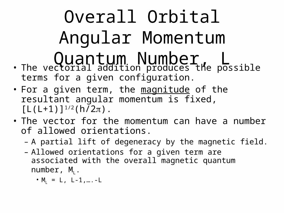
Overall Orbital Angular Momentum Quantum Number, L
• The vectorial addition produces the possible terms for a given configuration.
• For a given term, the magnitude of the resultant angular momentum is fixed, [L(L+1)]1/2(h/2).
• The vector for the momentum can have a number of allowed orientations.– A partial lift of degeneracy by the magnetic field.– Allowed orientations for a given term are associated with the
overall magnetic quantum number, ML.• ML = L, L-1,….-L
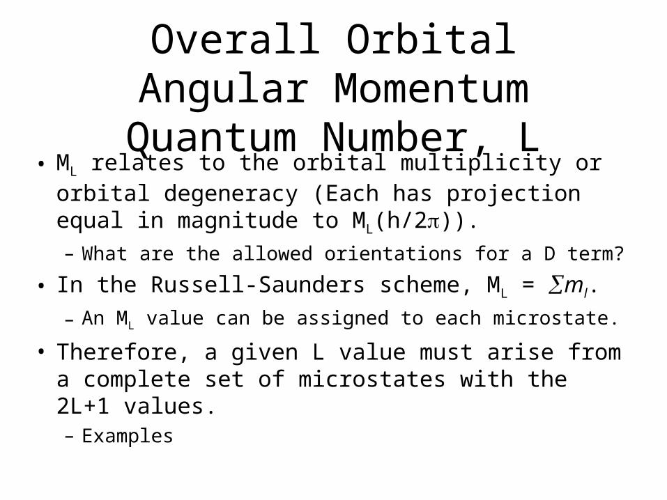
Overall Orbital Angular Momentum Quantum Number, L
• ML relates to the orbital multiplicity or orbital degeneracy (Each has projection equal in magnitude to ML(h/2)).– What are the allowed orientations for a D term?
• In the Russell-Saunders scheme, ML = ml.
– An ML value can be assigned to each microstate.
• Therefore, a given L value must arise from a complete set of microstates with the 2L+1 values.– Examples
Overall Spin Quantum Number, S
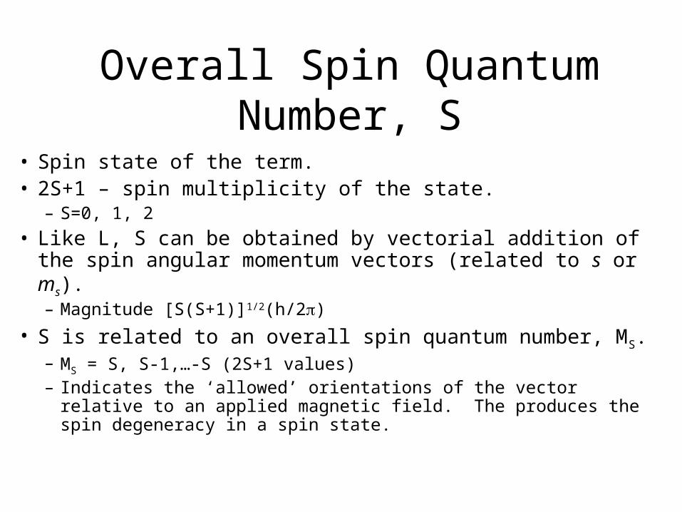
• Spin state of the term.• 2S+1 – spin multiplicity of the state.
– S=0, 1, 2
• Like L, S can be obtained by vectorial addition of the spin angular momentum vectors (related to s or ms).– Magnitude [S(S+1)]1/2(h/2)
• S is related to an overall spin quantum number, MS.– MS = S, S-1,…-S (2S+1 values)– Indicates the ‘allowed’ orientations of the vector relative to an applied
magnetic field. The produces the spin degeneracy in a spin state.
Overall Spin Quantum Number, S
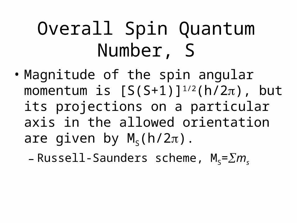
• Magnitude of the spin angular momentum is [S(S+1)]1/2(h/2), but its projections on a particular axis in the allowed orientation are given by MS(h/2).
– Russell-Saunders scheme, MS=ms
In Summary
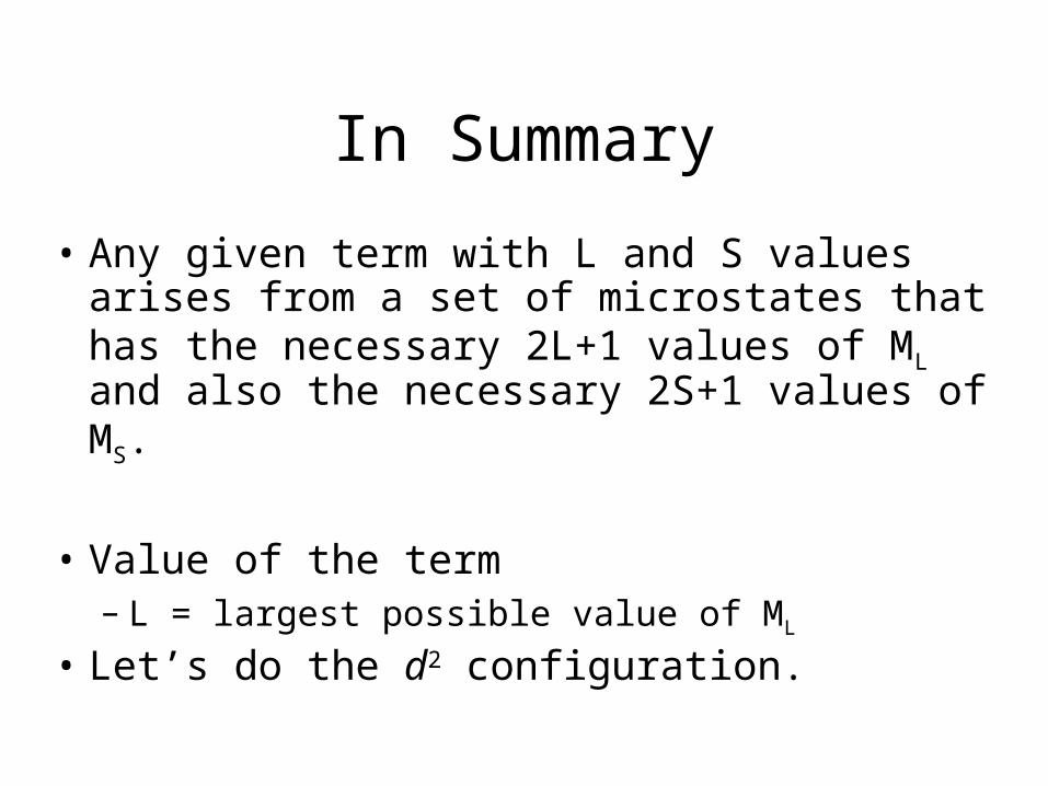
• Any given term with L and S values arises from a set of microstates that has the necessary 2L+1 values of ML and also the necessary 2S+1 values of MS.
• Value of the term – L = largest possible value of ML
• Let’s do the d2 configuration.
Determining Microstates
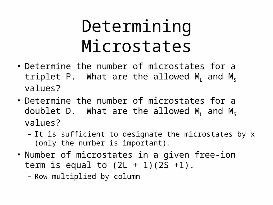
• Determine the number of microstates for a triplet P. What are the allowed ML and MS values?
• Determine the number of microstates for a doublet D. What are the allowed ML and MS values?– It is sufficient to designate the microstates by x (only the
number is important).
• Number of microstates in a given free-ion term is equal to (2L + 1)(2S +1).– Row multiplied by column
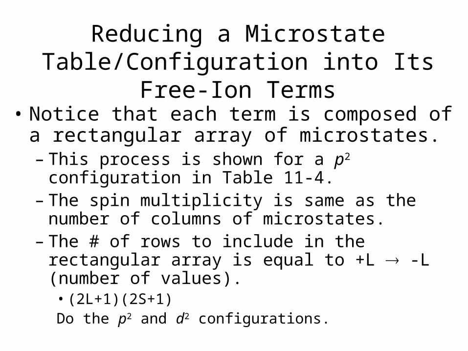
Reducing a Microstate Table/Configuration into Its Free-Ion Terms
• Notice that each term is composed of a rectangular array of microstates.– This process is shown for a p2 configuration in Table
11-4.– The spin multiplicity is same as the number of columns
of microstates.– The # of rows to include in the rectangular array is
equal to +L -L (number of values).• (2L+1)(2S+1)Do the p2 and d2 configurations.
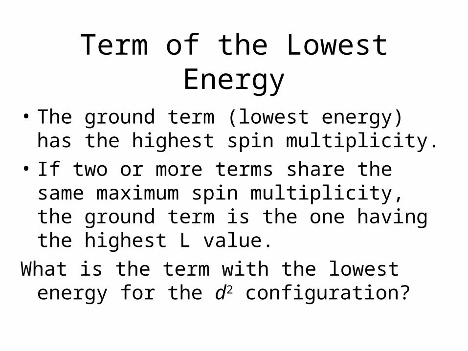
Term of the Lowest Energy
• The ground term (lowest energy) has the highest spin multiplicity.
• If two or more terms share the same maximum spin multiplicity, the ground term is the one having the highest L value.
What is the term with the lowest energy for the d2 configuration?
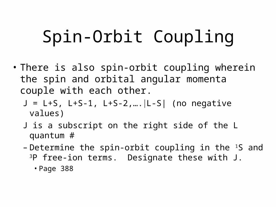
Spin-Orbit Coupling
• There is also spin-orbit coupling wherein the spin and orbital angular momenta couple with each other.J = L+S, L+S-1, L+S-2,….L-S| (no negative values)
J is a subscript on the right side of the L quantum #– Determine the spin-orbit coupling in the 1S and 3P
free-ion terms. Designate these with J.• Page 388
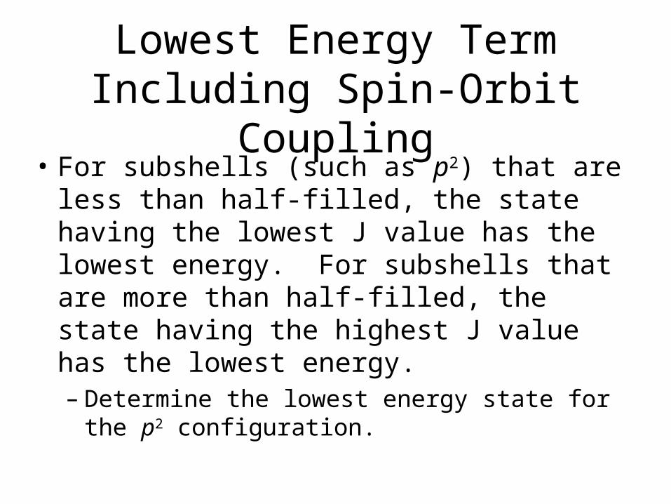
Lowest Energy Term Including Spin-Orbit Coupling
• For subshells (such as p2) that are less than half-filled, the state having the lowest J value has the lowest energy. For subshells that are more than half-filled, the state having the highest J value has the lowest energy.– Determine the lowest energy state for the p2
configuration.
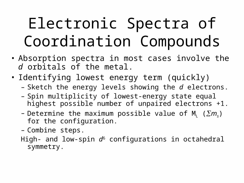
Electronic Spectra of Coordination Compounds
• Absorption spectra in most cases involve the d orbitals of the metal.
• Identifying lowest energy term (quickly)– Sketch the energy levels showing the d electrons.– Spin multiplicity of lowest-energy state equal highest
possible number of unpaired electrons +1.– Determine the maximum possible value of ML (ms) for the
configuration.– Combine steps.High- and low-spin d6 configurations in octahedral symmetry.
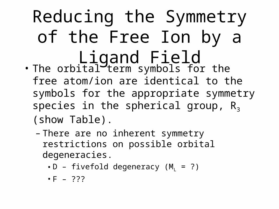
Reducing the Symmetry of the Free Ion by a Ligand Field
• The orbital term symbols for the free atom/ion are identical to the symbols for the appropriate symmetry species in the spherical group, R3 (show Table).
– There are no inherent symmetry restrictions on possible orbital degeneracies.
• D – fivefold degeneracy (ML = ?)
• F – ???
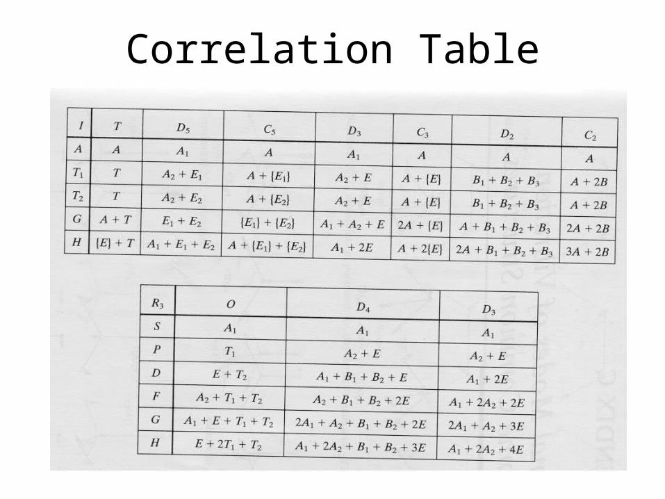
Correlation Table
Reducing the Symmetry of the Free Ion by a Ligand Field
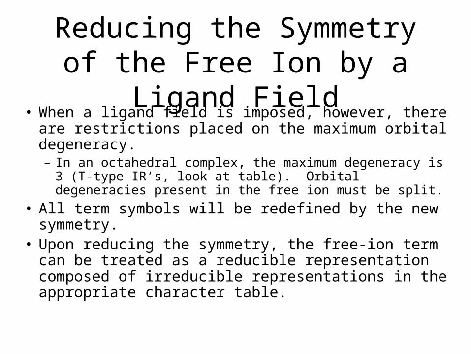
• When a ligand field is imposed, however, there are restrictions placed on the maximum orbital degeneracy.– In an octahedral complex, the maximum degeneracy is 3 (T-
type IR’s, look at table). Orbital degeneracies present in the free ion must be split.
• All term symbols will be redefined by the new symmetry.• Upon reducing the symmetry, the free-ion term can be
treated as a reducible representation composed of irreducible representations in the appropriate character table.
Reducing the Symmetry of the Free Ion by a Ligand Field
• The total number of microstates, Dt, remains the same.
• Do the d1 configuration.– What does this split into when an octahedral field is
imposed?– How many microstates are possible when imposing the
ligand field?The new ligand-field terms will retain the original spin
multiplicities found in the free-ion terms.Examine
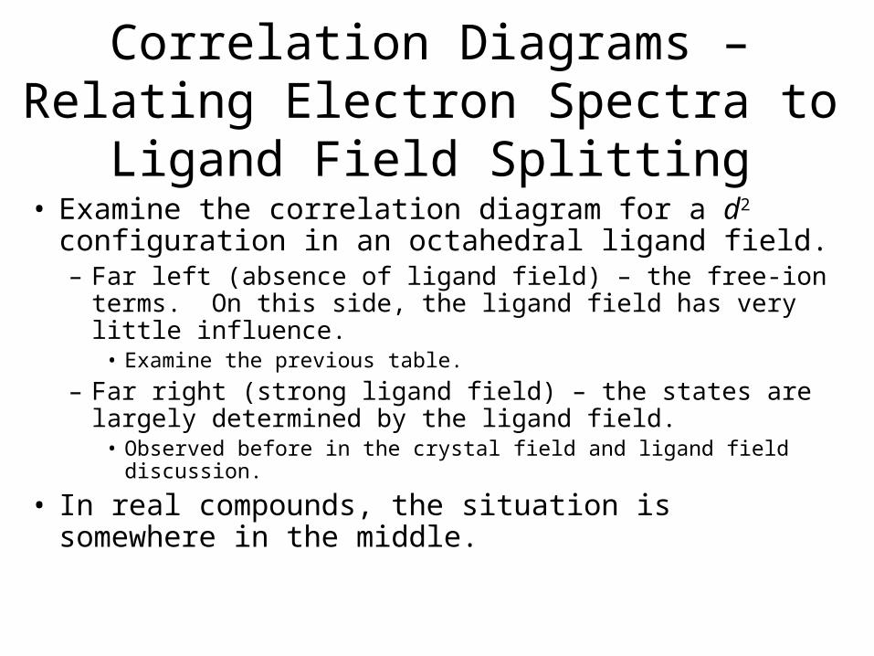
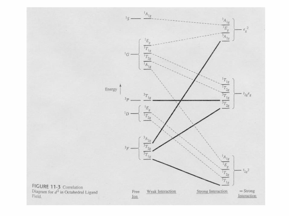
Correlation Diagrams – Relating Electron Spectra to Ligand Field Splitting
• Examine the correlation diagram for a d2 configuration in an octahedral ligand field.– Far left (absence of ligand field) – the free-ion terms. On this
side, the ligand field has very little influence.• Examine the previous table.
– Far right (strong ligand field) – the states are largely determined by the ligand field.
• Observed before in the crystal field and ligand field discussion.
• In real compounds, the situation is somewhere in the middle.
Splitting of Free-Ion Terms
• Irreducible representations are produced.– Examine the correlation diagram and the Oh table.
• Table 11-6
– Each state has symmetric characteristics of that IR.– IRs are also obtained from the strong-field limit
configurations (right side of table).
• The IRs on the right and left sides must ‘correlate’.
Selection Rules for Transitions
• Transitions between states of the same parity are forbidden.– Laporte Selection Rule
• Transitions between states of different spin multiplicities are forbidden.– 4A2 4T1 and 4A2 2A2
Discuss how the rules are relaxed on the expected absorption intensities.
Tanabe-Sugano Diagrams
• Special correlation diagrams useful in the interpretation of electronic spectra.– Lowest energy state is plotted along the horizontal axis.
o/B (field strength)
– Vertical axis is the measure of the energy above the ground state
• E/B
B = Racah parameter, a measure of the repulsion between terms of the same multiplicity.
– Lines connecting states of the same symmetry cannot cross.
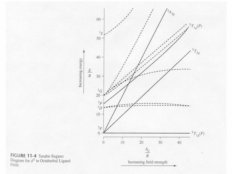
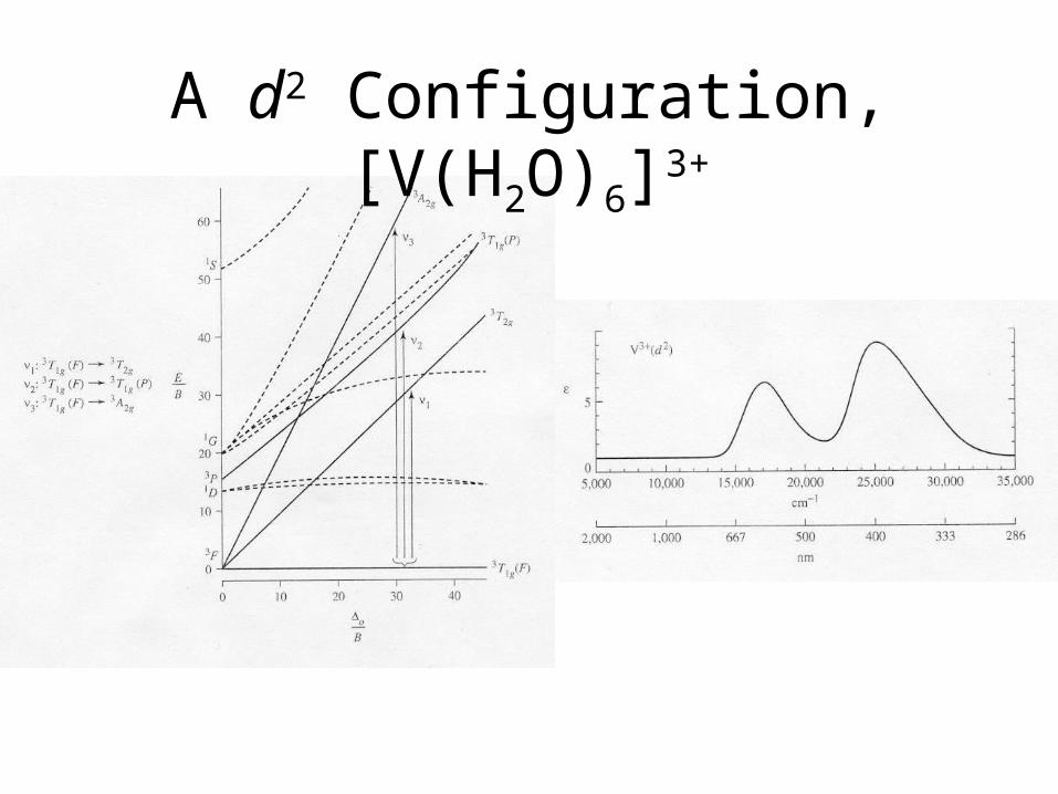
A d2 Configuration, [V(H2O)6]3+
Electron Configurations
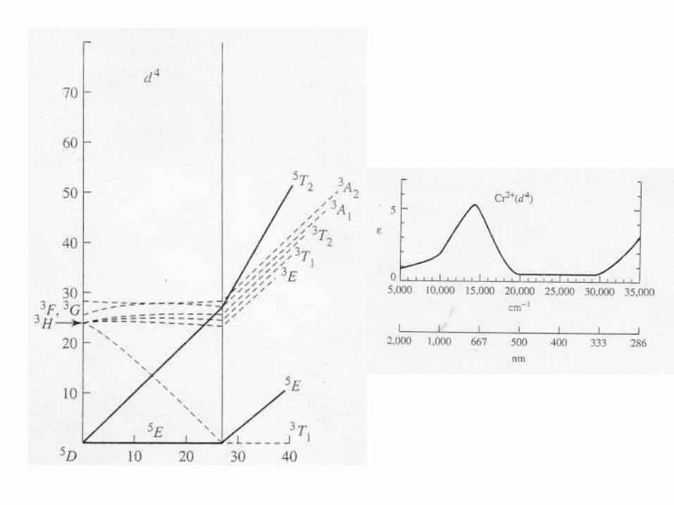
• The diagrams of d2-d8 are illustrated in Figure 11-7.• There is a vertical line near the center of d4-d7 diagrams.
What does the vertical line represent? What happens once the line is crossed?
• In some cases, the absorption bands are off-scale (x-axis) or obscured by the charge-transfer bands (discussed later).
• Discuss the terms for the configurations. They are not the same as observed for the orbital terms.

Jahn-Teller Distortions
• Spectrum of the [Ti(H2O)6]3+ complex.– The complex has a d1 configuration (Fig. 11-8).
– Go over terms for the configurations.
– Why are there two overlapping bands?• If degenerate orbitals are asymmetrically occupied a distortion will
occur to remove the degeneracy.
• Jahn-Teller distortion is usually only significant for asymmetrically occupied eg orbitals.– The others cannot be resolved.
– The most common distortion is along the z-axis (elongation).
Symmetry Labels for Configurations
• Symmetry labels for electron configurations match their degeneracies.– T = triply degenerate asymmetrical state– E = doubly degenerate asymmetrical state– A or B = nondegenerate
Do a few without Jahn Teller splitting/distortion.
• Effect of a D4h field.