
Coordinated Electric Vehicle Charging with Reactive Power ...
9
1 Coordinated Electric Vehicle Charging with Reactive Power Support to Distribution Grids Jingyuan Wang, Student Member, IEEE, Guna R. Bharati, Member, IEEE, Sumit Paudyal, Member, IEEE, O˘ guzhan Ceylan, Member, IEEE, Bishnu P. Bhattarai, Member, IEEE, and Kurt S. Myers, Member, IEEE Abstract—We develop hierarchical coordination frameworks to optimally manage active and reactive power dispatch of number of spatially distributed electric vehicles (EVs) incorporating distribution grid level constraints. The frameworks consist of detailed mathematical models, which can benefit the operation of both entities involved, i.e., the grid operations and EV charging. The first model comprises of a comprehensive optimal power flow model at the distribution grid level, while the second model represents detailed optimal EV charging with reactive power support to the grid. We demonstrate benefits of coordinated dispatch of active and reactive power from EVs using a 33- node distribution feeder with large number of EVs (more than 5,000). Case studies demonstrate that, in constrained distribution grids, coordinated charging reduces the average cost of EV charging if the charging takes place at non-unity power factor mode compared to unity power factor. Similarly, the results also demonstrate that distribution grids can accommodate charging of increased number of EVs if EV charging takes place at non-unity power factor mode compared to unity power factor. Index Terms—Electric vehicles, optimization, distribution grid, demand response, reactive power control. I. NOMENCLATURE Subscripts e EV number, eset = {e | e ∈ Z, 0 <e ≤ e max }. i Node number, iset = {i | i ∈ Z, 0 <i ≤ i max }. j Series element between node i and i +1, jset = {j | j ∈ Z, 0 <j ≤ j max }. k Time interval, kset = {k | k ∈ Z, 0 <k ≤ k max }. m Node with base loads, m ∈ iset. r Receiving end. s Sending end. t Time when EVs are grid connected, t ∈ kset. t Time when EVs are off grid, t ∈ kset. Superscripts ba Base load. ct Load curtailment. ev EV loads. fl Flexible loads. il Constant current load. This work was supported by the National Science Foundation under Grant ECCS-1751460. Paper no. TII-17-0738. J. Wang and S. Paudyal are with Department of Electrical and Computer Engineering, Michigan Technological University, Houghton, MI, USA, Emails: {jwang11,sumitp}@mtu.edu; G. R. Bharati is with OPAL-RT Technologies, CO, USA, Email: [email protected]; O. Ceylan is with Kadir Has University, Istanbul, Turkey, Email: [email protected]; B. P. Bhattarai is with Pacific Northwest National Laboratory, WA, USA, Email: [email protected]; K. S. Myers is with Idaho National Laboratory, ID, USA, Email: [email protected] loss Loss. max Maximum value. min Minimum value. pl Constant power load. sh Load shift. ss Substation. zl Constant impedance load. Parameters Δk Time interval. η Efficiency. λ 1 ,λ 2 Weighting factor. ρ Energy price. θ Power factor angle. A,B,C,D ABCD parameter matrices. E EV battery’s energy. I 0 Constant current. P 0 Constant active power. Q0 Constant reactive power. R Socket rating. S State of charge. S0 Desired SOC. Z 0 Constant impedance. Variables Ψ, Ω 1 , Ω 2 Objective function values. F Fairness index. I Complex current vector. ¯ I Complex conjugate of current vector. P Active power. Q Reactive power. V Complex voltage Vector. Functions Real part of a complex number. Imaginary part of a complex number. II. I NTRODUCTION E LECTRIC vehicles (EVs), due to their sizable power ratings and flexibility of charging, possess great demand response potential in electric power grids. EV aggregation not only benefits the operations of distribution grids, this could support system-wide frequency regulation, load following services, etc [1]–[3]. Despite the benefits EVs provide to the grids [4]–[8], high penetration of EVs adversely impact power grids in case of uncoordinated charging. High penetration of EV leads to several issues on distribution feeders including
Transcript of Coordinated Electric Vehicle Charging with Reactive Power ...
1
Coordinated Electric Vehicle Charging with
Reactive Power Support to Distribution GridsJingyuan Wang, Student Member, IEEE, Guna R. Bharati, Member, IEEE, Sumit Paudyal, Member, IEEE,
Oguzhan Ceylan, Member, IEEE, Bishnu P. Bhattarai, Member, IEEE, and Kurt S. Myers, Member, IEEE
Abstract—We develop hierarchical coordination frameworks tooptimally manage active and reactive power dispatch of numberof spatially distributed electric vehicles (EVs) incorporatingdistribution grid level constraints. The frameworks consist ofdetailed mathematical models, which can benefit the operation ofboth entities involved, i.e., the grid operations and EV charging.The first model comprises of a comprehensive optimal powerflow model at the distribution grid level, while the second modelrepresents detailed optimal EV charging with reactive powersupport to the grid. We demonstrate benefits of coordinateddispatch of active and reactive power from EVs using a 33-node distribution feeder with large number of EVs (more than5,000). Case studies demonstrate that, in constrained distributiongrids, coordinated charging reduces the average cost of EVcharging if the charging takes place at non-unity power factormode compared to unity power factor. Similarly, the results alsodemonstrate that distribution grids can accommodate charging ofincreased number of EVs if EV charging takes place at non-unitypower factor mode compared to unity power factor.
Index Terms—Electric vehicles, optimization, distribution grid,demand response, reactive power control.
I. NOMENCLATURE
Subscripts
e EV number, eset = e | e ∈ Z, 0 < e ≤ emax.
i Node number, iset = i | i ∈ Z, 0 < i ≤ imax.
j Series element between node i and i+ 1,
jset = j | j ∈ Z, 0 < j ≤ jmax.
k Time interval, kset = k | k ∈ Z, 0 < k ≤ kmax.
m Node with base loads, m ∈ iset.
r Receiving end.
s Sending end.
t Time when EVs are grid connected, t ∈ kset.
t′ Time when EVs are off grid, t′ ∈ kset.
Superscripts
ba Base load.
ct Load curtailment.
ev EV loads.
fl Flexible loads.
il Constant current load.
This work was supported by the National Science Foundation under GrantECCS-1751460. Paper no. TII-17-0738.
J. Wang and S. Paudyal are with Department of Electrical and ComputerEngineering, Michigan Technological University, Houghton, MI, USA,Emails: jwang11,[email protected]; G. R. Bharati is with OPAL-RTTechnologies, CO, USA, Email: [email protected]; O. Ceylan is withKadir Has University, Istanbul, Turkey, Email: [email protected];B. P. Bhattarai is with Pacific Northwest National Laboratory, WA, USA,Email: [email protected]; K. S. Myers is with Idaho NationalLaboratory, ID, USA, Email: [email protected]
loss Loss.
max Maximum value.
min Minimum value.
pl Constant power load.
sh Load shift.
ss Substation.
zl Constant impedance load.
Parameters
∆k Time interval.
η Efficiency.
λ1, λ2 Weighting factor.
ρ Energy price.
θ Power factor angle.
A,B,C,D ABCD parameter matrices.
E EV battery’s energy.
I0 Constant current.
P0 Constant active power.
Q0 Constant reactive power.
R Socket rating.
S State of charge.
S0 Desired SOC.
Z0 Constant impedance.
Variables
Ψ,Ω1,Ω2 Objective function values.
F Fairness index.
I Complex current vector.
I Complex conjugate of current vector.
P Active power.
Q Reactive power.
V Complex voltage Vector.
Functions
< Real part of a complex number.
= Imaginary part of a complex number.
II. INTRODUCTION
ELECTRIC vehicles (EVs), due to their sizable power
ratings and flexibility of charging, possess great demand
response potential in electric power grids. EV aggregation not
only benefits the operations of distribution grids, this could
support system-wide frequency regulation, load following
services, etc [1]–[3]. Despite the benefits EVs provide to the
grids [4]–[8], high penetration of EVs adversely impact power
grids in case of uncoordinated charging. High penetration of
EV leads to several issues on distribution feeders including

3
c) applications that demonstrate coordinated reactive power
dispatch of EVs combined with active power can result
in higher EV penetration without impacting the grid.
The rest of the paper is organized as follows: Section III
describes the mathematical modeling of distribution grid and
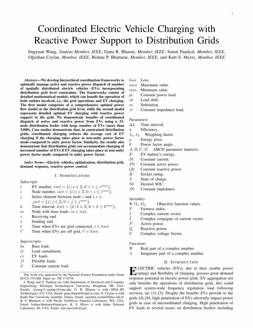
EVs. Section IV presents and discusses key results of case
studies carried out to coordinate charging of thousands of EVs
in a 33-node distribution system. A summary of the presented
work is discussed in Section V.
III. MATHEMATICAL MODELING
At the grid level, we have extended prior work in [37]
on distribution optimal power flow (DOPF) model to create
upper bounds on net active and reactive powers for EVs, load
shifting, and load curtailment on EV charging. At the EV
aggregation level, we have extended previous work in [8], [22],
[23] on optimal EV scheduling models by including reactive
power support from the EVs. Key mathematical modeling and
constraints are discussed next.
A. Distribution Grid Component Model
The DOPF model is built using individual grid components
and circuit laws. The mathematical models are developed in
terms of branch current and nodal voltages. The conductors
and cables are modeled using π-equivalent circuits. Detailed
descriptions of these models can be found in [37].
For each series element, ABCD parameters are used to
model sending/receiving end currents and voltages,[
Vi,k
Is,j,k
]
=
[Aj Bj
Cj Dj
] [Vi+1,k
Ir,j,k
]
(1)
Loads are modeled as shunt components. Impedance-
current-power (ZIP) load model is used for the base loads
which are non-flexible loads in the system. For base loads,
Vm,k = Z0m,k Izlm,k (2)
∣∣Iilm,k
∣∣(∠Vm,k − ∠Iilm,k
)=
∣∣I0ilm,k
∣∣∠θm,k (3)
Vm,k Iplm,k = P0m,k +
√−1Q0m,k (4)
Equation (2), (3), and (4) represent constant impedance,
constant current, constant power part of the ZIP loads.
To represent the current balance at node, the following
equation is used,
Branch currents︷ ︸︸ ︷
Ir,j−1,k = Is,j,k +
ZIP load currents︷ ︸︸ ︷
Izli,k + Iili,k + Ipli,k +I
fli,k (5)
where superscript fl is used to denote flexible loads, such as
EVs. The flexible loads in (5) are assumed to be connected at
nodes where base loads are connected, i.e., at nodes m.
B. Electric Vehicle Load Optimization Model
Total cost of charging EVs are minimized from EVA’s
point of view. The objective function can be written as,
Ψm =∑
k
ρk∑
e
P evm,e,k ∆k (6)
Equation (6) represents cost of charging EVs at node m on
the distribution grid.
The mathematical model of EVs are developed based on
SOC, initial SOC, final SOC desired by the EV owners, and
the time instances when EVs are connected to the grid. The
SOC of EVs are given by,
Sm,e,t = Sm,e,t−1 + ηm,e
P evm,e,t ∆k
Emaxm,e
(7)
Electric power consumed by the EV must always be within
the rating of the charging socket,
P ev2
m,e,k +Qev2
m,e,k ≤ R2m,e (8)
where R represents the rating of charging socket.
SOC at the instance EV is off the grid must meet the SOC
desired by the EV owner,
Sm,e,t′ ≥ S0m,e (9)
Minimum and maximum allowed SOC are represented as,
Sminm,e ≤ Sm,e,t ≤ Smax
m,e (10)
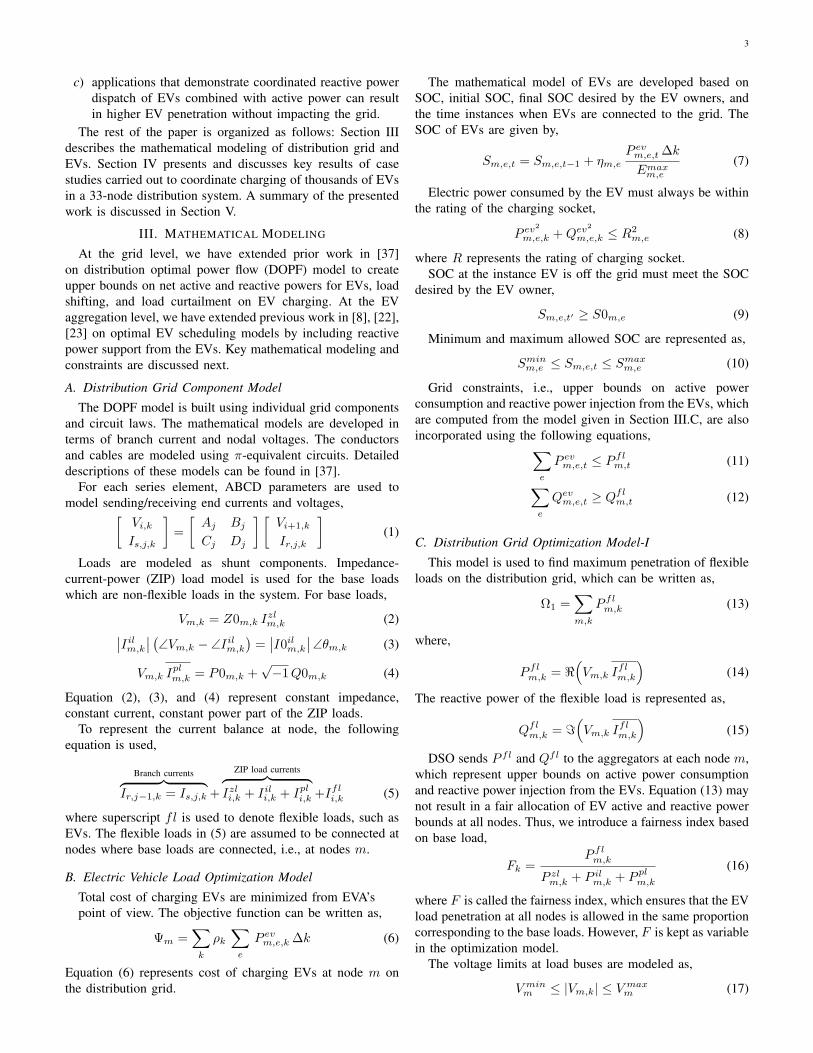
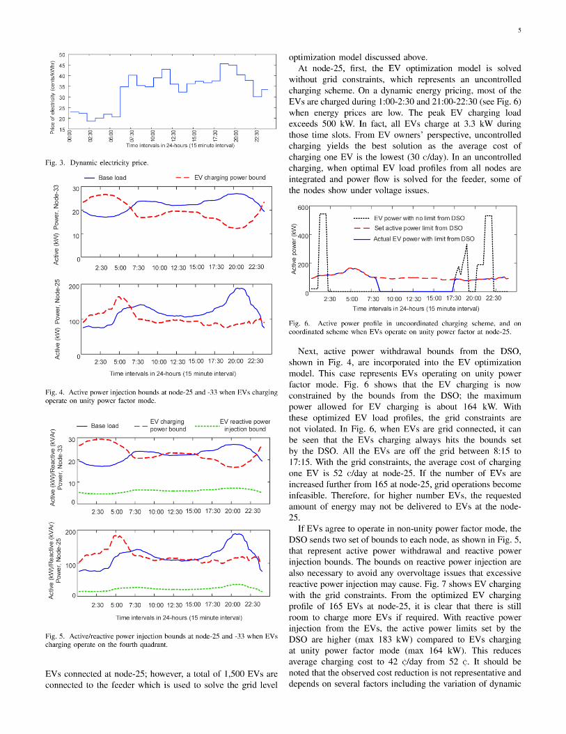
Grid constraints, i.e., upper bounds on active power
consumption and reactive power injection from the EVs, which
are computed from the model given in Section III.C, are also
incorporated using the following equations,∑
e
P evm,e,t ≤ P
flm,t (11)
∑
e
Qevm,e,t ≥ Q
flm,t (12)
C. Distribution Grid Optimization Model-I
This model is used to find maximum penetration of flexible
loads on the distribution grid, which can be written as,
Ω1 =∑
m,k
Pflm,k (13)
where,
Pflm,k = <
(
Vm,k Iflm,k
)
(14)
The reactive power of the flexible load is represented as,
Qflm,k = =
(
Vm,k Iflm,k
)
(15)
DSO sends P fl and Qfl to the aggregators at each node m,
which represent upper bounds on active power consumption
and reactive power injection from the EVs. Equation (13) may
not result in a fair allocation of EV active and reactive power
bounds at all nodes. Thus, we introduce a fairness index based
on base load,
Fk =P
flm,k
P zlm,k + P il
m,k + Pplm,k
(16)
where F is called the fairness index, which ensures that the EV
load penetration at all nodes is allowed in the same proportion
corresponding to the base loads. However, F is kept as variable
in the optimization model.
The voltage limits at load buses are modeled as,
V minm ≤ |Vm,k| ≤ V max
m (17)

9
[18] S. Shao, M. Pipattanasomporn, and S. Rahman, “Demand response asa load shaping tool in an intelligent grid with electric vehicles,” IEEE
Transactions on Smart Grid, vol. 2, no. 4, pp. 624–631, Dec. 2011.[19] C. K. Wen, J. C. Chen, J. H. Teng, and P. Ting, “Decentralized plug-in
electric vehicle charging selection algorithm in power systems,” IEEE
Transactions on Smart Grid, vol. 3, no. 4, pp. 1779–1789, Dec. 2012.[20] J. de Hoog, T. Alpcan, M. Brazil, D. A. Thomas, and I. Mareels,
“Optimal charging of electric vehicles taking distribution networkconstraints into account,” IEEE Transactions on Power Systems, vol. 30,no. 1, pp. 365–375, Jan. 2015.
[21] B. Bhattarai, B. Bak-Jensen, P. Mahat, J. Pillai, and M. Maier,“Hierarchical control architecture for demand response in smart gridscenario,” in Proc. IEEE PES APPEEC, Dec. 2013, pp. 1–6.
[22] G. R. Bharati and S. Paudyal, “Coordinated control of distribution gridand electric vehicle loads,” Electric Power Systems Research, vol. 140,pp. 761 – 768, 2016.
[23] S. Paudyal and G. R. Bharati, “Hierarchical approach for optimaloperation of distribution grid and electric vehicles,” in Proc. IEEE
PowerTech, Jun. 2015, pp. 1–6.[24] Z. Li, Q. Guo, H. Sun, and S. Xin, “A decentralized optimization method
to track electric vehicle aggregator’s optimal charging plan,” in Proc.
IEEE PES General Meeting, July 2014, pp. 1–5.[25] L. Gan, U. Topcu, and S. H. Low, “Optimal decentralized protocol for
electric vehicle charging,” IEEE Transactions on Power Systems, vol. 28,no. 2, pp. 940–951, May 2013.
[26] H. Xing, M. Fu, Z. Lin, and Y. Mou, “Decentralized optimal schedulingfor charging and discharging of plug-in electric vehicles in smart grids,”IEEE Transactions on Power Systems, vol. 31, no. 5, pp. 4118–4127,Sept. 2016.
[27] B. Bhattarai, M. Levesque, M. Maier, B. Bak-Jensen, and J. Pillai,“Optimizing electric vehicle charging coordination over a haterogeneousmesh network in a scaled-down smart grid testbed,” IEEE Transactions
on Smart Grid, vol. 6, no. 2, pp. 784–794, Jan. 2015.[28] M. N. Mojdehi and P. Ghosh, “Modeling and revenue estimation of EV
as reactive power service provider,” in Proc. IEEE PES GM, 2014.[29] M. Mojdehi and P. Ghosh, “An On-Demand Compensation Function
for an EV as a Reactive Power Service Provider,” IEEE Transactions
on Vehicular Technology, vol. 65, no. 6, pp. 4572–4583, 2016.[30] M. C. Kisacikoglu, B. Ozpineci, and L. M. Tolbert, “Examination
of a PHEV bidirectional charger system for V2G reactive powercompensation,” in Proc. IEEE Applied Power Electronics Conference
and Exposition, Feb. 2010, pp. 458–465.[31] M. Kesler, M. C. Kisacikoglu, and L. M. Tolbert, “Vehicle-to-Grid
Reactive Power Operation Using Plug-In Electric Vehicle BidirectionalOffboard Charger,” IEEE Transactions on Industrial Electronics, vol. 61,no. 12, pp. 6778–6784, Dec. 2014.
[32] M. C. Kisacikoglu, B. Ozpineci, and L. M. Tolbert, “EV/PHEVBidirectional Charger Assessment for V2G Reactive Power Operation,”IEEE Transactions on Power Electronics, vol. 28, no. 12, pp. 5717–5727,Dec. 2013.
[33] M. C. Kisacikoglu, M. Kesler, and L. M. Tolbert, “Single-phase on-board bidirectional pev charger for v2g reactive power operation,” IEEE
Transactions on Smart Grid, vol. 6, no. 2, pp. 767–775, March 2015.[34] B. Sun, T. Dragicevic, M. Savaghebi, J. C. Vasquez, and J. M. Guerrero,
“Reactive power support of electrical vehicle charging station upgradedwith flywheel energy storage system,” in Proc. IEEE PowerTech, June2015, pp. 1–6.
[35] A. Rabiee, H. F. Farahani, M. Khalili, J. Aghaei, and K. M. Muttaqi,“Integration of plug-in electric vehicles into microgrids as energy andreactive power providers in market environment,” IEEE Transactions on
Industrial Informatics, vol. 12, no. 4, pp. 1312–1320, Aug. 2016.[36] S. Paudyal, O. Ceylan, B. P. Bhattarai, and K. S. Myers, “Optimal
coordinated ev charging with reactive power support in constraineddistribution grids,” in Proc. IEEE PES General Meeting, Jul. 2017, pp.1–5.
[37] S. Paudyal, C. Cañizares, and K. Bhattacharya, “Optimal operation ofdistribution feeders in smart grids,” IEEE Transactions on Industrial
Electronics, vol. 58, no. 10, pp. 4495–4503, Oct. 2011.[38] M. E. Baran and F. F. Wu, “Network reconfiguration in distribution
systems for loss reduction and load balancing,” IEEE Transactions on
Power Delivery, vol. 4, no. 2, pp. 1401–1407, Apr. 1989.[39] S. I. Vagropoulos and A. G. Bakirtzis, “Optimal bidding strategy for
electric vehicle aggregators in electricity markets,” IEEE Transactions
on Power Systems, vol. 28, no. 4, pp. 4031–4041, Nov 2013.[40] S. H. Low, “Convex relaxation of optimal power flow–Part I:
Formulations and equivalence,” IEEE Transactions on Control of
Network Systems, vol. 1, no. 1, pp. 15–27, Mar. 2014.
Jingyuan Wang (S’17) received the B.E. degreein Electrical Engineering from Hebei Universityof Technology, Tianjin, China, in 2013. She iscurrently working towards the Ph.D. degree inElectrical Engineering at Michigan TechnologicalUniversity, USA. Her current research interestsinclude power system operations, power systemoptimization, integration of renewable resources,power system hardware-in-the-loop simulation, andcomputational performance improvement of large-scale power grids.
Guna R. Bharati (S’16, M’18) received B.E inElectrical Engineering from Tribhuvan University,Nepal in 2010 and PhD in Electrical Engineeringfrom Michigan Technological University in 2017.His research focus is on power system optimization,building-grid and vehicle-grid integration. Currently,he is working as a Research Engineer at OPAL-RT and is responsible for developing power systemmodels and HIL simulation.
Sumit Paudyal (S’07, M’13) received the M.Sc.from the University of Saskatchewan, Canada, in2008; and the PhD. from the University of Waterloo,Canada, in 2012, all in Electrical Engineering. Hejoined the Department of Electrical Engineering,Michigan Technological University, USA, as anAssistant Professor in 2012. His current researchinterests include distribution grid operations, powersystem protection, power system real-time hardwaresimulations, and optimization techniques.
Oguzhan Ceylan (S’08, M’13) received the M.Sc.and Ph.D. degree in Computational Science andEngineering from Istanbul Technical University,Turkey, in 2003 and 2012, respectively. He wasa Postdoctoral Researcher at the University ofTennessee, Knoxville, USA from 2013 to 2015.Currently he is an Assistant Professor at KadirHas University, Turkey. His research interestsinclude smart grids, integration of renewables intodistribution systems, and intelligent optimizationmethods.
Bishnu P. Bhattarai (S’12,M’15) received hisM.Sc. in Power System Engineering from TribhuvanUniversity, Nepal and Osaka Sangyo University,Japan, in 2010 and Ph.D. in Electrical Engineeringfrom Aalborg University, Denmark in 2015. He iscurrently working as a Distribution Power Engineerat Pacific Northwest National Laboratory (PNNL),Richland, USA. His research interests include gridintegration of renewable energy resource, advancedmodeling and simulation of smart grids, and gridresiliency.
Kurt S. Myers (M’15) is a Project Managerand Staff Electrical Engineer at Idaho NationalLaboratory (INL), Idaho, USA. He received theB.Sc. degree in physics from the Universityof Washington in 1992 and the M.Sc. degreein electrical engineering from Washington StateUniversity in 1997. He has more than 20 years ofexperience at the laboratory working with multiplegovernment, industry, and university collaborators.He is also a licensed Professional Engineer in theState of Idaho.